
Recommended
More Related Content
What's hot
What's hot (20)
Similar to Portable and mobile radiographic equipments [Autosaved].pptx
Similar to Portable and mobile radiographic equipments [Autosaved].pptx (20)
Recently uploaded
Recently uploaded (20)
Portable and mobile radiographic equipments [Autosaved].pptx
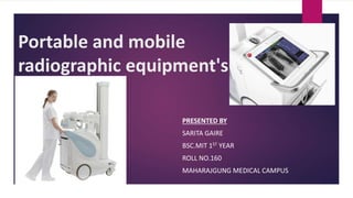
- 1. Portable and mobile radiographic equipment's PRESENTED BY SARITA GAIRE BSC.MIT 1ST YEAR ROLL NO.160 MAHARAJGUNG MEDICAL CAMPUS
- 2. Content Introduction Portable radiographic equipment's Components of portable equipment Advantages and disadvantages of portable radiographic equipment’s Mobile equipment's Components of mobile equipment Capacitor discharge unit Battery powered unit Advantages and disadvantages of mobile radiographic equipment. Mobile image intensifier High tension generator. Advancements Machine used in our department
- 3. INTRODUCTION Machines that are used for severely ill and unable patients, who cannot be brought in the radiology department. Used when surgeons requires x- ray guidance during their work in the operation theater. These machines can be divided into two types: Portable and Mobile equipment.
- 4. Portable Portable x-ray unit were discovered in 1912. Portable units are small and light in weight. Can be dismantled and carried usually by one person around the hospital or even at patients home. Have relatively low radiation output. unit in 1912.
- 5. Figure: Fujifilm FDR Xair portable machine Figure: old portable machine THEN NOW
- 6. Components of Portable unit. Tube head. Tube stand. Control unit.(control panel).
- 7. 1.Tube head. A.X-ray tube. - the tube is small stationary anode - self rectified tube. - single small focal spot of 1.0mm. - has limit of exposure less than mobile x-ray equipment. B. High tension generator. -Tube and generator are enclosed in one oil tank , described as tank construction and the whole enclosure called the tube head. High tension generator Xray tube Oil filled tank Tube head
- 8. 2.Tube stand - it supports for the tube head. 3. Control unit(control panel) - on off switch. - kv and mAs selection. - exposure switches.
- 9. Control unit
- 10. Advantages of portable. Simple and handy which can be folded into small package whenever needed for transportation. It is very useful and advantages in during sports and military. Allows radiographic examination in locations limited by the availability of a standard electrical supply. Used in remote areas where electricity is also not available.
- 11. Disadvantages of portable. Have relatively low radiation output. it is difficult to maintain in aspects of radiation protection. Can be damaged by external source.
- 12. Mobile Mobile means capable of being moved. Mobile X-ray equipment's are Bigger and heavier than portable and needs to be pushed or motorized by human power. Is movable, but because of its heavy weight and size it can only be wheeled along flat surfaces with motion brakes. Have higher radiation output than portable.
- 13. Mobile units in 1940-1955 and now.
- 14. Components of mobile equipment Tube Tube stand High tension generator. Control unit(control panel)
- 15. 1.Tube - Rotating anode x-ray tube. - dual filament with dual focal spot. - focal spot = about 1.0mm for fine focus. = 2.0 mm for broad focus. 2.Tube stand • a strong vertical column mounted on the base that supports the cross arm which carries the x-ray tube. • To prevent damage to cables movements.
- 16. Tube stand can be divided into 5 major movements. 1.Rotation movement. -around the center of the column(R). 2.Cross arm movement - the extension of the tube head away from center of the column (A). 3.Rotation around the axis of the crossarm(D). 4.Angulation movement. - across the long axis of the tube head(B). 5.Vertical movement up and down main column(H).
- 17. High tension generator Provides a maximum output of 125kvp and 300mA. Includes full wave rectification provided by means of selenium rectifiers. The mobile x-ray unit consists of an earthed steel tank filled with oil, which house the high-tension generator rectifier and filament transformer. Connected to the x-ray tube by mean of high-tension cable.
- 18. Control unit (control panel) Located behind the generator tank on the base unit. It consist of 1. main on and off switch. 2. mA selector. 3. kv selector. 4. focal spot selector. 5. body parts selector. 6. exposure indicator .(ready and exposure).
- 19. Hand switch A hand switch is a switch used for the x- ray exposure process. Transport handle The rudder grip is the handle used when moving in the mobile x-ray unit. Cassette box holder Place to put cassette when the plane is moved.
- 20. Mobile classification can classified in two ways 1. By power supply a.Capacitor discharge unit. • it does not operate on batteries. • It can produce x-ray by store energy in capacitor then discharge through it. • Contains two metal plates that hold electrical charge. b. Battery powered unit. • Uses two sets of lead acid or nickel-cadmium batteries. • One set powers driving of the machine. • One set provides power to the x-ray tube.
- 21. 2. By output: Low Power Mobiles: 10 to 30mA and 40 to 90 kVp. Average Power Mobiles:100 to 150 mA and 40-95 kVp. High power mobiles : up to 300 mA and 125 kVp.
- 22. Capacitor discharge unit. When charge circuit is activated, voltage from HTT charges a capacitor up to the kilo voltage required for the exposure. The capacitor becomes source of power for x ray exposure. It is disconnected from the charging circuit and connected to the x ray tube for exposure. its discharge through tube constitutes the mAs of the radiographic exposure factors.
- 24. • Rotating anode tube with single focal spot size of 1.2mm and heat storage capacity of 80,000 HU. Grid controlled: • Uses a third electrode i.e., focusing cup to control flow of electrons from filament to target. • Voltage across filament-grid produces electric field along path of electron beam that pushes electrons closer. • Exposure start & stop controlled by voltage on grid. • Large enough negative voltage on grid blocks tube current from cathode to anode. Xray tube: +
- 25. • Automatic charging circuit for charging the capacitor. • The kV range is from 30kv to 125kv. If preselected Kv is altered after charging, the tube voltage is automatically adjusted to the new value. • A single mAs control, rather than mA and exposure time being selected separately. The units are usually designed to operate at a high, fixed mA value, so that exposure time becomes the main variable by default. control unit:
- 26. Advantages of capacitor discharge unit. • Light weight ,smaller and easier to movement. • Require much less time to charge than battery units. • No battery usage. Disadvantages of capacitor discharge unit. • Can’t handle thick body parts due to voltage drop during exposure. • Must be charge prior to each use.
- 27. Battery powered mobile unit. Also called cord less mobile unit. Lithium/Ni-Cd batteries are used as a source of energy for x ray exposure . The generator is referred to as constant potential generator (CPG). Power supply is used to charge the batteries. The batteries produces low voltage DC charge.
- 28. Major components of battery powered x-ray machine.
- 29. Advantages of battery powered unit. • Stores considerable energy to generate x rays. It can store 10,000 mAs. • Make exposures independent of power supply mains. • Supplies constant output of KV and mA through out the exposure. • Used in case of emergency power failure.
- 30. Disadvantages of battery powered unit. • Needs special care and maintenance. • Batteries must be charged • Require regular batteries maintenance • Heavy and hard to control .
- 31. Care and maintenance. • The unit should be left connected to the mains power supply of 220V. • Naked flames or lighted cigarettes should not be held near the batteries when they are being charged. • The acid level in the batteries should be checked every 2 weeks.
- 32. Advantages and disadvantages of mobile unit. High radiation output than portable is the advantage And heavier than portable unit is the disadvantage.
- 33. Mobile image intensifiers unit. They are used in OT (operating theater) for fluoroscopic examination. This reduces the number of radiographs taken and saves the time of surgery.
- 34. Important features of mobile unit for fluoroscopy. The x-ray tube. The image intensifier. High tension generator. Control console.
- 35. The x-ray tube and image intensifier. • Mounted opposite to each other at the end of C-arm • Xray tube head is at the lower end of C-arm and the image intensifier is at the upper end with input phosphor facing towards the x-ray tube. • The tube head houses the x-ray tube. • The x-ray tube is stationary anode and two focal spots.
- 36. • the c-arm is mounted on a cross arm which extend from a carriage carried on a vertical support rising from the control console. • The x-ray tube and the image intensifier are held directly opposite to each other with x-ray beam permanently centered to the input phosphor. • At the back of image intensifier is the television pickup tube so that image can be viewed on monitor. • The input phosphor of the image intensifier is cesium iodide which gives good contrast.
- 39. Movements • The vertical support can be raised and lowered, and the cross arm can be extended through the carriage. • The x-ray tube and image intensifier are attached to the c-arm and move together. • The c-arm can be moved in any direction, so the equipment enables a good range of position and projections to be used without wastage of time.
- 40. High tension generator • The x-ray tube and high-tension generator are together in the tube head. • High tension generator are single phase with full wave rectification provided by silicon rectifiers.
- 41. Fig: sequence of transference of signal
- 42. Control console. • Kilovoltage for fluoroscopy or radiography range from 50kv to 105kv. • mA settings for fluoroscopy range from 0.1 to0.3mA . • For radiography, the kv and mA are linked .i.e. 50mA at 55kv. 40mA at 80kv. 30mA at 105kv. • The timer for radiographic exposure is electronic and gives range from 0.1 to 0.3sec.
- 43. • For the television chain, circuit includes controls which allow the image to be transposed right to left and inverted top to bottom. • There is control for memory circuit with two magnetic disc that is image storage is possible. • There is facility for pulsed fluoroscopy with electronic selector. the rates provided vary from 1 flash per sec to 1 flash every 5 sec. • This allows to monitor dynamic events without subjecting the patient to continuous radiation.
- 44. Advancements. High frequency generator mobile units. Computed radiography mobile x-ray unit. Direct digital radiography mobile x-ray unit.
- 45. High Frequency Generator Recently high frequency generators are more popular for use in radiology for mammography and mobile units. One of significant advantages is its compact design. Converts low frequency (50 HZ) to high frequency (5KHZ) pulsed DC, by altering waveform of incoming electrical circuit which is subsequently increased to kilovolts, rectified and sent to the x-ray tube.
- 46. Produces a nearly constant voltage wave form with extremely low ripple(<1%). Provides great x-ray quality(effective energy) and quantity. More efficient. More expensive than previous mobile units. Uses inverter circuit. The DC power supply produces a constant voltage from either a single phase or three phase input line source. inverter circuit creates the high frequency AC waveform.
- 47. This AC current supplies the high voltage transformer and creates a waveform of fixed high voltage and corresponding low current. After rectification and smoothing two high voltage capacitor on the secondary circuits accumulates electron charges. These capacitors produce a voltage across the x-ray tube, that depends upon the accumulated charges.
- 48. Fig: Block diagram of high frequency generator
- 49. Computed radiography mobile x-ray unit. It is a mobile imaging system used for capturing X-ray images using a CR imaging plate. It allows for convenient on-site imaging in various healthcare settings, such as hospitals, clinics, emergency rooms, and nursing homes.
- 50. Computed radiography mobile x ray unit.
- 51. Direct digital radiography mobile x ray unit. It is a mobile imaging system used for capturing X- ray images using a digital detector. Unlike computed radiography (CR), which uses an imaging plate, DR directly captures the X-ray image in a digital format. This technology offers several advantages. These system represents an evolutionary move in mobile diagnostic imaging equipment and includes unique features in terms of operability, mobility and image quality.
- 52. these system meets todays and future clinical demands providing the premium solution for • Immediate image processing • An efficient clinical workflow • A rapid display of high-quality clinical images • Fast integration into the hospital network.
- 55. Mobile equipment in our hospital. Used in ICU ONLY. Battery powered. Rotating anode. Mains supply 100-220v /50/60hz. Kvp ranges from 40 to 125Kvp. mAs ranges from 0.32-320mAs Body part selection mode. Size selection mode. SIMADZU
- 56. SIEMENS used in pediatric ICU only. Capacitor discharge. Rotating anode. Mains supply 190-240v/50hz Kvp range 40-100 mAs range 0.32-80 mAs There is no body part selection and size selection in this one .
- 57. uDR(United Imaging) Used in all wards and intensive care units. Features battery powered(lithium) Rotating anode Dual focal spot of 1.2 and 0.6 Tube Filtration of 1.5mm AL Collimator filtration of 1mm AL Mains supply:-230V /50hz/60hz. range upto 150kvp and 320mAs.
- 58. 19” LCD touchscreen with body part, size selection which presents all data clearly. With the help of a tablet pc, operators can do imaging remotely, thus which optimally protects them from radiation damage. Electric driving system for easy transport. Multi angle and flexible operation. Fine motion control for higher mobility. Dual battery for longer power supply.
- 59. Cassette/detector used for DR and CR mobile machine CR imaging plate(Cassette) DR wireless imaging plate
- 60. REFERENCES • Chesney's equipment for student radiographers • Christensen's physics of diagnostic radiology • www.slideshare.com • Various websites and PowerPoint presentations.
- 61. Thank you
- 62. Questions 1. What are the features of portable unit? 2. What are the features of mobile unit? 3. What are the components of portable unit? 4. How does a capacitor discharge mobile unit work? 5. Why high frequency generator is used in portable unit? 6. What are the advantages and disadvantages of battery powered unit? 7. What are the features of mobile image intensifier unit? 8. Which type of x ray unit is used in our department for ward radiography?
Editor's Notes
- As shown in figure right side image shows old portable machine and left side shows the latest model portable machine which looks like camera and easy to handle.
- Tube head include x ray tube and high tension generator. X ray tube operating self rectified and connected directly across the secondaru winding of the high tension transformer.
- Kvp and ma vary garne lai rheostat vanxa
- High tension generator contains high tension transformer.
- Pahlye vacuum diode Solid state dioide Ma ahlye selenium
- When the charge button is pressed, the capacitor is charged through high tension source by connections at G1 and G2. when required kV is reached, charging is automatically stopped, and the lamp indicates ready. After charging has stopped when exposure button is pressed, capacitor is connected to tube at X1 and X2.it discharges through the tube and constitutes the x ray exposure.
- Powersupply from nickel cadium batteries goes to dc chopper here the dc voltage is converted into pusating dc of high frequency , and that high frequency is supplied to primary winding of HTT and from the secondary winding of transformer we get high voltage ac , and that high voltage ac goes to rectifier and converts ac into pulasating dc and that pulsating dc is smoothed with the help of capacitor circuit and that smoothed dc goes is supplied to x ray tube for exposure.
- Input phosphor convert x-ray photons into light photons.
- This c arm contains xary tube and image intensifier in opposite end and the tv is connected to image intensifier to view the image . The whole c arm is mounted on the cross arm here the carriage help to extend the cross arm and supported on vertical support.
- Image of fluoroscopic mobile c arm
- In image intensifier intensification takes place and brightens the image.
- Here input ac power supplied to the rectifier and converted into pulsating dc that smoothed with the help of capacitor filter that dc is supplied to the inductor circuit (chopper) here thar dc is conveted into high frequency pulsating dc now that high frequency pulasating dc is passed through primary winding of high voltage transformer and converted into high voltage ac that high voltage ac is passed through a series of rectifier and converted into high voltage pulsating dc now that pulsating dc is smoothed and supplied to xray tube with the help of capacitor circuit.
- Have low radiation output Have high radiation output