SlideShare a Scribd company logo
1 of 63
1
MODULE:2
HUMAN ORGAN SYSTEMS AND BIODESIGNS-1
Prof.P.L.Puthani, Dept. of . Mech. Engg BLDEA’s V.P.Dr. P.G.Halakatti
2
Prof.P.L.Puthani, Dept. of . Mech. Engg BLDEA’s V.P.Dr. P.G.Halakatti
3
Prof.P.L.Puthani, Dept. of . Mech. Engg BLDEA’s V.P.Dr. P.G.Halakatti
2.1 Brain as a CPU System
Brain is highly sophisticated & complex information processing system, similar to a CPU.
Both Brain & CPU receive & process inputs, store information & perform calculations to
produce outputs.
Way of storing & processing of information in both of them are different.
4
Prof.P.L.Puthani, Dept. of . Mech. Engg BLDEA’s V.P.Dr. P.G.Halakatti
Comparison Chart
Basis for Comparison Brain Computer
Construction Neurons & synapses ICs, transistors, diodes,
capacitors, transistors, etc.
Memory growth Increases each time by
connecting synaptic links
Increases by adding more
memory chips
Backup systems Built-in backup system Backup system is constructed
Manually
Memory power 100 teraflops (100 trillion
calculations/seconds)
100 million megabytes
Memory density 107 circuits/cm3 1014 bits/cm3
Energy consumption 12 watts Gigawatts
Information storage Stored in electrochemical &
electric impulses.
Stored in numeric & symbolic
form (binary bits).
5
Prof.P.L.Puthani, Dept. of . Mech. Engg BLDEA’s V.P.Dr. P.G.Halakatti
Comparison Chart continued
Basis for Comparison Brain Computer
Size and weight Volume = 1500 cm3 &
weight ≈ 3.3 pounds.
Variable weight and size form
few grams to tons.
Transmission of
information
Uses chemicals to fire the
action potential in the neurons.
Communication is achieved
through electrical coded
signals.
Information processing
power
Low High
Input/output equipment Sensory organs Keyboards, mouse, web
cameras, etc.
Structural organization Self-organized Pre-programmed structure
Parallelism Massive Limited
Reliability and damageability
Properties
Brain is self-organizing, self
maintaining
and reliable.
Computers perform a
monotonous job and can't
correct itself.
6
Prof.P.L.Puthani, Dept. of . Mech. Engg BLDEA’s V.P.Dr. P.G.Halakatti
Architecture
7
Prof.P.L.Puthani, Dept. of . Mech. Engg BLDEA’s V.P.Dr. P.G.Halakatti
Prefrontal Cortex functions as similar to ALU.
Higher-level cognitive functions such as decision making & problem solving are identified by prefrontal
cortex.
Information is stored in memory units of CPU.
Human brain has several regions dedicated to memory storage, including the hippocampus & amygdala.
8
Prof.P.L.Puthani, Dept. of . Mech. Engg BLDEA’s V.P.Dr. P.G.Halakatti
CNS (Central Nervous System ) and PNS (Peripheral Nervous System)
9
Prof.P.L.Puthani, Dept. of . Mech. Engg BLDEA’s V.P.Dr. P.G.Halakatti
Central Nervous System
• Consists of brain & spinal cord
• Receives, processes & integrates
sensory information and transmit
commands to the rest of the body.
• Brain acts as the command center,
receives & processes sensory inputs
and generates motor outputs.
• Spinal cord acts as a relay center,
transmitting information between the
brain and peripheral nerves.
Peripheral Nervous
System
• Located outside the brain and spinal
cord
• Transmits sensory information from
the periphery of the body (such as the
skin, muscles & organs) to the CNS,
and transmits commands from the
CNS to the periphery.
• PNS can be further divided into the
somatic nervous system (Voluntary
movements) and the autonomic
nervous system (Involuntary i.e
heart rate, digestion, respiration)
10
Prof.P.L.Puthani, Dept. of . Mech. Engg BLDEA’s V.P.Dr. P.G.Halakatti
Signal Transmission
Occurs through the firing of nerve cells or neurons
known as Synaptic transmission.
Information transferred through Dendrites by
generating electric impulse down to Axons & Synaptic
terminals.
Postsynaptic neurons & the balance of
neurotransmitter levels can influence brain
function, including mood, learning & memory.
Influenced by various forms of synaptic plasticity,
including Long-term Potentiation (LTP) and
Long-term Depression (LTD).
11
Prof.P.L.Puthani, Dept. of . Mech. Engg BLDEA’s V.P.Dr. P.G.Halakatti
Neuron Neuro Transmitter
12
Prof.P.L.Puthani, Dept. of . Mech. Engg BLDEA’s V.P.Dr. P.G.Halakatti
EEG (Electro Encephalo Graphy)
Non-invasive method for measuring the electrical activity of the brain.
Records the electrical signals generated by the brain‘s neurons as they communicate with each other.
Signals are recorded through electrodes placed on the scalp and the resulting EEG pattern provides
information about the synchronized electrical activity of large population of neurons
13
Prof.P.L.Puthani, Dept. of . Mech. Engg BLDEA’s V.P.Dr. P.G.Halakatti
EEG Applications
Diagnosis of Epilepsy (Abnornal activity in brain)
Sleep Studies (Sleep Pattern)
Brain-Computer Interfaces (BCI) {Prosthetics Limbs}
Research on Brain Function (Reading, Problem-Solving)
Diagnosis of Brain Disorders (Dementia,Parkinson’s Dis., Traumatic brain injury)
Anesthesia Monitoring (During Surgery- Safe and Comfortable state)
Monitoring Brain Activity during Coma (Level of brain function)
14
Prof.P.L.Puthani, Dept. of . Mech. Engg BLDEA’s V.P.Dr. P.G.Halakatti
EEG Signals and Types of Brain Activity
15
Prof.P.L.Puthani, Dept. of . Mech. Engg BLDEA’s V.P.Dr. P.G.Halakatti
Robotic Arms for Prosthetics
Advanced prosthetic devices use robotics technology
to restore functionality of individuals with upper limb
amputations.
Consists of motors, actuators & sensors to mimic
the movements of a human arm & hand, allowing the
wearer to perform tasks such as reaching, grasping &
manipulating objects.
Direct control through muscle signals (myoelectric
control) or brain-machine interfaces, which use
electrodes implanted in the brain or placed on the
scalp to detect and interpret brain activity.
16
Prof.P.L.Puthani, Dept. of . Mech. Engg BLDEA’s V.P.Dr. P.G.Halakatti
Robotic Arm Prosthetic Direct Control through Muscle Signals (Myoelectric Control)
 Electrical signals generated by the wearer's remaining muscles control the movement of the prosthetic.
Electrodes placed on the skin over the remaining muscle are used to detect & interpret the electrical signals
generated by the muscle contractions.
Advantage of being directly controlled by the user, allowing for a more intuitive & natural interaction with
the prosthetic.
High level of control & precision, as the electrical signals are unique to each individual perform a wide range of
movements.
17
Prof.P.L.Puthani, Dept. of . Mech. Engg BLDEA’s V.P.Dr. P.G.Halakatti
Myoelectric control systems can be complex and may require extensive rehabilitation and
training to use effectively.
Maintenance needed to ensure proper function.
Additionally, the system may not be suitable for individuals with muscle weakness or other
conditions that affect the ability to generate strong electrical signals.
18
Prof.P.L.Puthani, Dept. of . Mech. Engg BLDEA’s V.P.Dr. P.G.Halakatti
Robotic Arm Prosthetic by Brain-Machine Interfaces (BMI)
19
Prof.P.L.Puthani, Dept. of . Mech. Engg BLDEA’s V.P.Dr. P.G.Halakatti
Robotic Arm Prosthetic by Brain-Machine Interfaces (BMI) cont.
A technology that allows user to control a robotic
arm prosthetic directly with their brain activity.
Electrodes are placed on the scalp to detect user's
brain signals.
 When the user thinks about moving the prosthetic
arm,
 Brain activity is detected & signals are sent to a
control unit, which uses algorithms to interpret the
signals & control the movement of the prosthetic.
User can control the movement of the prosthetic in
real-time by thinking about the desired movement.
20
Prof.P.L.Puthani, Dept. of . Mech. Engg BLDEA’s V.P.Dr. P.G.Halakatti
Robotic Arm Prosthetic by Brain-Machine Interfaces (BMI) cont.
Advantage of providing a direct & intuitive connection between
the user's brain & the prosthetic.
High level of control and precision.
Sensory feedback to the user, to experience the sensation of
touch.
BMIs can be complex & invasive systems, require surgical
implantation & ongoing maintenance to ensure proper function.
Unsuitable for individuals with conditions that affect brain
activity or unable to generate strong enough brain signals to
control the prosthetic effectively.
Ongoing research & development is aimed at improving the
performance & accessibility of BMIs, as well as increasing their
ease of use and reliability.
21
Prof.P.L.Puthani, Dept. of . Mech. Engg BLDEA’s V.P.Dr. P.G.Halakatti
Engineering Solutions for Parkinson’s Disease
Neurodegenerative disorder that affects movement & motor
function.
Several engineering solutions aimed at improving the quality of life.
Deep Brain Stimulation (DBS): involves the implantation of
electrodes into specific regions of the brain to deliver electrical
stimulation which help to relieve tremors, stiffness & difficulty with
movement.
Exoskeletons: wearable devices that provide support & assistance
for individuals with mobility issues to improve balance, reduce
tremors & increase overall mobility.
Telerehabilitation: telecommunication technology to provide
physical therapy & rehabilitation services to individuals.
22
Prof.P.L.Puthani, Dept. of . Mech. Engg BLDEA’s V.P.Dr. P.G.Halakatti
Smartwatch Applications: monitor symptoms of Parkinson's disease, such as tremors & provide
reminders and prompts for medication & exercise.
Virtual Reality: Rehabilitation and therapy for individuals with Parkinson's disease, providing
interactive and engaging environments for patients to practice movements, improve
coordination and balance.
Technologies are not a cure for Parkinson's disease and should be used in conjunction with other
forms of treatment and care.
23
Prof.P.L.Puthani, Dept. of . Mech. Engg BLDEA’s V.P.Dr. P.G.Halakatti
Artificial Brain
Known as an Artificial General Intelligence (AGI) or a
synthetic brain.
Hypothetical machine with cognitive abilities similar to
those of a human brain
 Machine that can learn, reason & solve problems in the
same way that humans do.
 Technical, ethical & philosophical challenges need to be
addressed.
Artificial Intelligence (AI) systems are designed to
perform specific tasks such as image recognition, speech
recognition or decision making.
Exciting and rapidly advancing field of research that has the
potential to change the world in many ways
24
Prof.P.L.Puthani, Dept. of . Mech. Engg BLDEA’s V.P.Dr. P.G.Halakatti
Eye as a Camera System
25
Prof.P.L.Puthani, Dept. of . Mech. Engg BLDEA’s V.P.Dr. P.G.Halakatti
• Both the eye and a camera capture light and convert it into an image.
Main components of the eye
•Cornea: Transparent outer layer of the eye functions like a camera lens,
bending light to focus it onto the retina.
•Iris: Diaphragm in a camera, controlling the amount of light that enters
the eye.
•Pupil: Aperture in a camera, adjusting the size to control the amount of
light entering the eye.
•Retina: Camera film or sensor, capturing the light and converting it into
electrical signals that are sent to the brain.
•Optic Nerve: Cable connecting the camera to a computer, transmitting
the electrical signals from the retina to the brain.
26
Prof.P.L.Puthani, Dept. of . Mech. Engg BLDEA’s V.P.Dr. P.G.Halakatti
27
Prof.P.L.Puthani, Dept. of . Mech. Engg BLDEA’s V.P.Dr. P.G.Halakatti
 In both the eye and a camera, the captured light is transformed into an
image by the lens and the light-sensitive component.
 The eye processes the image further, allowing for visual perception,
while a camera stores the image for later use.
 Eye is much more complex than a camera and has several additional
functions, such as adjusting for different levels of light and adjusting focus,
that are not found in a camera.
 Ability to perceive depth and color, as well as adjust to movements and
provide a continuous, real-time image to the brain.
28
Prof.P.L.Puthani, Dept. of . Mech. Engg BLDEA’s V.P.Dr. P.G.Halakatti
Architecture of Rod and Cone Cells
Rod Cells
•Photoreceptor cells in the retina of the eye
that are responsible for detecting light and
transmitting signals to the brain for the
perception of vision, especially in low
light conditions.
•Contain a protein called rhodopsin that
absorbs light and triggers a chain of events
leading to the activation of neural signals.
• Rods are more sensitive to light than
cone cells but do not distinguish color as
well.
29
Prof.P.L.Puthani, Dept. of . Mech. Engg BLDEA’s V.P.Dr. P.G.Halakatti
Cone Cells
•Photoreceptor cells in the retina of the eye that are responsible for color
vision and visual acuity (sharpness of vision).
•Three types of cone cells, each containing a different photopigment
sensitive to different wavelengths of light (red, green, and blue), which
allow for the perception of color.
•Cones are less sensitive to light than rod cells but provide better visual
acuity and color discrimination.
•They are concentrated in the fovea, the central part of the retina
responsible for detailed and sharp vision.
30
Prof.P.L.Puthani, Dept. of . Mech. Engg BLDEA’s V.P.Dr. P.G.Halakatti
Architecture
• Rod and cone cells have a similar basic
structure, but there are some differences that are
crucial for their different functions.
• Both types of cells have a photoreceptor outer
segment that contains the photopigment
(rhodopsin in rods and photopigments in cones)
that absorbs light and triggers a change in
membrane potential.
• Inner segment contains the cell's organelles,
including the nucleus and mitochondria.
31
Prof.P.L.Puthani, Dept. of . Mech. Engg BLDEA’s V.P.Dr. P.G.Halakatti
 Major difference between rod and cone cells is their
shape.
 Rod cells are elongated and cylindrical, while cone
cells are shorter and more conical in shape.
This difference in shape affects the distribution of
photopigments and the number of synaptic contacts
with bipolar and ganglion cells, which transmit the
signals to the brain.
 Rod cells have a single long outer segment, while
cone cells have several shorter segments.
 Rod cells make synapses with one bipolar cell, while
cone cells synapse with one of several bipolar cells
32
Prof.P.L.Puthani, Dept. of . Mech. Engg BLDEA’s V.P.Dr. P.G.Halakatti
Optical Corrections
• Devices or techniques used to improve or correct vision problems caused
by a refractive error in the eye.
• Refractive errors occur when light entering the eye is not properly
focused on the retina, leading to blurred vision. There are several types of
refractive errors,
1) Myopia (nearsightedness): Light is focused in front of the retina,
making distant objects appear blurry.
2) Hyperopia (farsightedness): Light is focused behind the retina, making
near objects appear blurry.
3) Astigmatism: Light is not focused evenly on the retina, leading to
blurred or distorted vision.
33
Prof.P.L.Puthani, Dept. of . Mech. Engg BLDEA’s V.P.Dr. P.G.Halakatti
Most common optical corrections include:
• Eyeglasses: Glasses with corrective lenses can be used to refocus light onto the
retina, improving vision.
• Contact lenses: Corrective lenses in the form of contacts sit directly on the cornea
and work similarly to eyeglasses.
• Refractive surgery: Surgicals LASIK (Laser-Assisted In Situ Keratomileusis) and
PRK (Photorefractive keratectomy), can reshape the cornea to correct refractive
errors.
Optical corrections can greatly improve visual acuity and quality of life for people
with refractive errors. However, it is important to have regular eye exams to
determine the appropriate correction and monitor eye health.
34
Prof.P.L.Puthani, Dept. of . Mech. Engg BLDEA’s V.P.Dr. P.G.Halakatti
Cataract
• Clouding of the lens of the eye that
affects vision.
•The lens, located behind the iris and
pupil, normally allows light to pass
through to the retina and produces
clear, sharp images.
• However, as we age or due to other
factors, the proteins in the lens can
clump together and cause the lens to
become opaque, leading to vision
problems.
35
Prof.P.L.Puthani, Dept. of . Mech. Engg BLDEA’s V.P.Dr. P.G.Halakatti
• Symptoms of a cataract include blurred or hazy vision, increased sensitivity to
glare and bright lights, faded or yellowed colors, and double vision in one eye.
• Cataracts can also cause frequent changes in prescription for eyeglasses or
contacts.
• Cataract surgery is a common and safe procedure to remove the cloudy lens
and replace it with an artificial lens.
• Most people experience improved vision within a few days after the procedure.
• Regular eye exams can help detect cataracts early and prevent vision loss.
36
Prof.P.L.Puthani, Dept. of . Mech. Engg BLDEA’s V.P.Dr. P.G.Halakatti
Lens Materials
Most common lens materials (Each with its own unique properties and benefits)
• Polymethyl methacrylate (PMMA): Plastic that has been used for many years in
artificial lenses. It is a durable and affordable material, but does not have the ability
to flex and adjust focus like the natural lens.
• Silicone: Soft, flexible material that is resistant to cracking and breaking.
• Acrylic: Acrylic is a lightweight, clear material that is similar in properties to
PMMA. It is often used in foldable (intraocular lenses) IOLs, which can be inserted
through a smaller incision.
• Hydrophobic acrylic: Acrylic material that has a special surface treatment that
helps to reduce glare and halos around lights.
• Hydrophilic acrylic: Acrylic material that is designed to be more compatible with
the natural fluid in the eye, reducing the risk of vision-threatening complications.
Choice of lens material - patient's individual needs, the surgeon's preference, and the
potential risks and benefits of each material.
37
Prof.P.L.Puthani, Dept. of . Mech. Engg BLDEA’s V.P.Dr. P.G.Halakatti
Bionic Eye or Artificial Eye
• Also known as a retinal implant, is a type of prosthetic device
that is surgically implanted into the eye to help restore vision to
people who have lost their sight due to certain conditions such
as retinitis pigmentosa or age-related macular degeneration.
• Consists of a camera, a processor, and an electrode array that
is attached to the retina.
• Camera captures images and sends signals to the processor,
which then transmits electrical stimulation to the electrodes in
the retina to stimulate the remaining healthy cells and restore
vision.
•The restored vision is not perfect, but it can help people with
vision loss to perform daily tasks more easily and safely.
38
Prof.P.L.Puthani, Dept. of . Mech. Engg BLDEA’s V.P.Dr. P.G.Halakatti
Working of Bionic Eye
39
Prof.P.L.Puthani, Dept. of . Mech. Engg BLDEA’s V.P.Dr. P.G.Halakatti
• Capturing images with a small camera and transmitting the information to a processing
unit that is attached to the eye.
• Processing unit then converts the visual information into electrical signals and sends
them to an electrode array that is surgically implanted onto the retina.
• Electrodes stimulate the remaining healthy cells in the retina, which then sends signals
to the brain to create the perception of vision.
•The restored vision is not perfect, but it can help people with vision loss to perform daily
tasks more easily and safely.
• Some bionic eyes only restore basic visual shapes and patterns, while others can provide
more detailed vision.
• Powered by a battery that is typically implanted behind the ear.
40
Prof.P.L.Puthani, Dept. of . Mech. Engg BLDEA’s V.P.Dr. P.G.Halakatti
Materials Used in Bionic Eye
• Silicon or other semiconducting materials for the camera & electrode array.
• Biocompatible materials for the casing of the device and the electrode array,
such as titanium or titanium alloys, to minimize the risk of infection and rejection
by the body.
• Conductive materials, such as platinum, iridium, or gold, for the electrodes in
the array to provide efficient electrical stimulation to the retina.
• Polymers, such as silicone or polyimide, for insulation and protection of the
electrodes and other components.
• Optical materials, such as glass or acrylic, for the lens of the camera.
• Biocompatible and flexible materials for the electrical connections between the
camera and the processing unit and between the processing unit and the electrode
array.
•Advanced computer algorithms and machine learning techniques are also used to
improve the accuracy and reliability of the bionic eye technology.
41
Prof.P.L.Puthani, Dept. of . Mech. Engg BLDEA’s V.P.Dr. P.G.Halakatti
Heart as a Pump System
42
Prof.P.L.Puthani, Dept. of . Mech. Engg BLDEA’s V.P.Dr. P.G.Halakatti
Architecture
43
Prof.P.L.Puthani, Dept. of . Mech. Engg BLDEA’s V.P.Dr. P.G.Halakatti
 Four chambers: Right atrium, Left atrium, Right ventricle, Left
ventricle.
 Blood enters the right atrium from the body and is pumped into the right
ventricle, which then pumps the blood to the lungs for oxygenation.
 Oxygenated blood returns to the heart and enters the left atrium, which
pumps the blood into the left ventricle. The left ventricle then pumps the
oxygenated blood out to the rest of the body.
 Between each chamber, there are one-way valves that ensure the blood
flows in the correct direction and prevent backflow.
 Surrounded by the pericardium, a sac that contains a small amount of
fluid and helps to protect and lubricate the heart as it beats.
44
Prof.P.L.Puthani, Dept. of . Mech. Engg BLDEA’s V.P.Dr. P.G.Halakatti
The Heart Beat
Heart's pumping action is
controlled by a complex
network of electrical and
chemical signals, which
generate the rhythm of the
heartbeat.
45
Prof.P.L.Puthani, Dept. of . Mech. Engg BLDEA’s V.P.Dr. P.G.Halakatti
•An electrical stimulus is generated in a special part of the heart muscle called
the sinus node (SA node).
• Small mass of special tissue in the right upper chamber of the heart (right
atrium).
• In an adult, the sinus node sends out a regular electrical pulse 60 to 100
times per minute.
• Electrical pulse travels down through the conduction pathways and causes
the heart's lower chambers (ventricles) to contract and pump out blood.
• The right and left atria are stimulated first and contract to push blood from
the atria into the ventricles.
• The ventricles then contract to push blood out into the blood vessels of the
body.
46
Prof.P.L.Puthani, Dept. of . Mech. Engg BLDEA’s V.P.Dr. P.G.Halakatti
Electrical Signalling – ECG Monitoring and Heart Related Issues
47
Prof.P.L.Puthani, Dept. of . Mech. Engg BLDEA’s V.P.Dr. P.G.Halakatti
 Heart's pumping action is controlled by electrical signaling, which
generates the rhythm of the heartbeat.
 Electrical signaling can be monitored using an electrocardiogram
(ECG), which records the electrical activity of the heart and provides
important information about the heart's function.
 An ECG measures the electrical signals produced by the heart as it
beats and generates a trace or waveform that reflects the electrical
activity of the heart.
 This trace can be used to diagnose heart conditions and monitor the
heart's function.
48
Prof.P.L.Puthani, Dept. of . Mech. Engg BLDEA’s V.P.Dr. P.G.Halakatti
Some common heart-related issues that can be diagnosed or monitored
using an ECG include:
 Arrhythmias: Abnormalities in the heart's rhythm or rate can
be detected using an ECG.
 Heart disease: Changes in the heart's electrical activity can
indicate the presence of heart disease, such as coronary artery
disease or heart attacks.
 Heart attack: Detecting changes in the heart's electrical
activity that indicate a lack of blood flow to the heart.
Overall, the ECG is a useful tool for diagnosing and monitoring heart-
related issues and helps to provide important information about the heart's
function and health.
49
Prof.P.L.Puthani, Dept. of . Mech. Engg BLDEA’s V.P.Dr. P.G.Halakatti
Reasons for Blockages of Blood Vessels
(A)damage (dead heart muscle)
caused by a heart attack,
(B) shows the coronary artery with
plaque buildup and a blood clot.
50
Prof.P.L.Puthani, Dept. of . Mech. Engg BLDEA’s V.P.Dr. P.G.Halakatti
Blockages in blood vessels, also known as arterial blockages or atherosclerosis, can occur for
several reasons:
 High cholesterol levels: Excessive amounts of low-density lipoprotein (LDL) cholesterol
in the blood can lead to the formation of plaque in the blood vessels, which can narrow or
block them.
 High blood pressure: Over time, high blood pressure can cause damage to the blood
vessels, leading to the formation of plaque and blockages.
 Smoking: Smoking can damage the inner walls of blood vessels and promote the buildup
of plaque, leading to blockages.
 Diabetes: People with uncontrolled diabetes are at a higher risk of developing blockages in
their blood vessels, due to damage to the blood vessels from high levels of glucose.
 Age: As people age, the blood vessels can become stiff and less flexible, increasing the
risk of blockages.
 Genetics: Some people may be predisposed to developing blockages in their blood vessels
due to genetic factors.
 Poor diet: A diet high in saturated fats, trans fats, and cholesterol can increase the risk of
developing blockages in the blood vessels.
51
Prof.P.L.Puthani, Dept. of . Mech. Engg BLDEA’s V.P.Dr. P.G.Halakatti
Design of Stents
 Stents are small, metal mesh devices that are used to treat blockages in
blood vessels.
 Typically used in procedures such as angioplasty, where a balloon catheter
is used to open up a blocked blood vessel and a stent is placed to keep it open.
52
Prof.P.L.Puthani, Dept. of . Mech. Engg BLDEA’s V.P.Dr. P.G.Halakatti
Design of stents can vary depending on the type of stent and the specific medical condition
it is used to treat.
 Shape: Cylindrical, helical, and spiraled, to match the shape of the blood vessel and
provide adequate support.
 Material: Stainless steel, cobalt- chromium, and nitinol (a type of metal that is flexible
and can return to its original shape after being expanded).
 Coating: Coated with different materials to prevent blood clots from forming and reduce
the risk of restenosis (recurrent blockage of the blood vessel).
 Expansion mechanism: Designed to expand in different ways, such as by balloon
inflation or self-expansion, depending on the type of stent and the specific medical
condition it is used to treat.
Overall, the design of stents plays an important role in their effectiveness and safety. Stents
must be designed to provide adequate support to the blood vessel, prevent restenosis, and
minimize the risk of complications such as blood clots.
53
Prof.P.L.Puthani, Dept. of . Mech. Engg BLDEA’s V.P.Dr. P.G.Halakatti
Pace Makers
 Small device that is surgically
implanted in the chest to regulate the
heartbeat.
 It is used to treat heart rhythm
disorders, such as bradycardia (a slow
heartbeat) or arrhythmias (abnormal
heart rhythms), by delivering electrical
impulses to the heart to regulate its
rhythm.
54
Prof.P.L.Puthani, Dept. of . Mech. Engg BLDEA’s V.P.Dr. P.G.Halakatti
The basic design of a pacemaker consists of:
 Generator: Main component of the pacemaker and contains a battery
and electronic circuitry to generate and control the electrical impulses.
 Leads: Thin wires that connect the generator to the heart and carry
the electrical impulses from the generator to the heart.
 Electrodes: The electrodes are located at the end of the leads and are
used to deliver the electrical impulses to the heart.
Pacemakers can be designed to work in different ways, including:
55
56
 Single-chamber pacemaker: A single-chamber pacemaker
delivers electrical impulses to either the right atrium or the right
ventricle of the heart to regulate its rhythm.
 Dual-chamber pacemaker: A dual-chamber pacemaker delivers
electrical impulses to both the right atrium and the right ventricle of
the heart to regulate its rhythm.
 Biventricular pacemaker: A biventricular pacemaker delivers
electrical impulses to both ventricles of the heart to coordinate their
contractions and improve heart function in people with heart failure.
Uses of high-quality materials and specialized manufacturing processes to ensure
their safety and reliability.
Materials used in the construction of pacemakers include:
• Medical-grade plastics: Polycarbonate, are used to construct the exterior of
the device and to provide insulation and protection for the internal
components.
• Metals: Stainless steel and titanium, are used in the construction of the leads
and electrodes to ensure their durability and long-lasting performance.
• Electronic components: Microprocessors, batteries, and capacitors, are used
to control the delivery of the electrical impulses and to provide power to the
device.
• Adhesives: Cyanoacrylate and epoxy, are used to secure the components of
the device and to provide insulation and protection for the internal
components. 57
Construction of a Pacemaker
 Medical device that delivers an
electric shock to the heart to
restore its normal rhythm in cases
of cardiac arrest or other life-
threatening heart rhythm
disorders.
 Defibrillators can be external
(placed on the chest) or internal
(implanted within the body).
58
Defibrillators
The basic design of a defibrillator consists of:
– Power source: The power source, typically a battery,
provides energy to deliver the electric shock to the heart.
– Electrodes: The electrodes are placed on the chest and
deliver the electric shock to the heart.
– Circuitry: The circuitry in the defibrillator controls the
delivery of the electric shock, including the timing,
strength, and duration of the shock.
– Display: A display on the defibrillator provides information
about the heart rhythm, battery life, and other relevant
information.
59
Automated External Defibrillators (AEDs)
• External defibrillators, also known as AEDs, are designed for use by
laypeople and are commonly found in public places such as airports,
shopping centers, and schools. They are relatively simple in design
and typically have voice prompts and visual cues to guide the user
through the process of delivering the electric shock.
Implantable Cardioverter Defibrillators (ICDs),
• Internal defibrillators, also known as ICDs, are surgically implanted
within the body and are used to treat people with a high risk of sudden
cardiac arrest. They are typically more complex in design, including
features such as continuous monitoring of the heart rhythm, and
automatic delivery of shocks when necessary.
60
Materials Used in the construction of defibrillators include:
• Medical-grade plastics: Polycarbonate, are used to construct the exterior
of the device and to provide insulation and protection for the internal
components.
• Metals: Stainless steel and titanium, are used in the construction of the
leads and electrodes to ensure their durability and long-lasting
performance.
• Electronic components: Microprocessors, batteries, capacitors, and
high-voltage transformers, are used to control the delivery of the
electrical impulses and to provide power to the device.
• Adhesives: Cyanoacrylate and epoxy, are used to secure the
components of the device and to provide insulation and protection for
the internal components.
61
Artificial Heart
62
 Device that is designed to replace
the functions of a damaged or failing
heart.
Temporary measure to support a
patient while they are waiting for a
heart transplant, or as a permanent
solution for people who are not eligible
for a heart transplant.
63
Two main types of artificial hearts:
 Total artificial heart is a self-contained device that completely
replaces the functions of the natural heart. It is used as a bridge to
transplant, meaning it provides temporary support to a patient while
they are waiting for a heart transplant.
 Heart assist devices, Devices that are surgically implanted into the
heart and work alongside the natural heart to support its functions.
While these devices are still in the early stages of development, they have
the potential to greatly improve the survival and well-being of people
with heart disease.

More Related Content

Similar to Module 2 (1).ppt

Thought Detection via BCI
Thought Detection via BCIThought Detection via BCI
Thought Detection via BCIAkhilesh Mishra
 
Brain computer interface
Brain computer interfaceBrain computer interface
Brain computer interfaceSharat045
 
Password system that are mind control
Password system that are mind controlPassword system that are mind control
Password system that are mind controlvivatechijri
 
Brain machine interface
Brain machine interface Brain machine interface
Brain machine interface ShaikYusuf5
 
Module 2:- HUMAN ORGAN SYSTEMS AND BIO DESIGNS
Module 2:- HUMAN ORGAN SYSTEMS AND BIO DESIGNSModule 2:- HUMAN ORGAN SYSTEMS AND BIO DESIGNS
Module 2:- HUMAN ORGAN SYSTEMS AND BIO DESIGNSDr. Pavan Kundur
 
Brain gate system document
Brain gate system documentBrain gate system document
Brain gate system documentSridhar Goud
 
Brain computer interface
Brain computer interfaceBrain computer interface
Brain computer interfaceSivapradeep R
 
Brain Computer Interface
Brain Computer Interface Brain Computer Interface
Brain Computer Interface Deepti Singh
 
Seminar braingate
Seminar braingateSeminar braingate
Seminar braingateritu kumari
 
IRJET- Precision of Lead-Point with Support Vector Machine based Microelectro...
IRJET- Precision of Lead-Point with Support Vector Machine based Microelectro...IRJET- Precision of Lead-Point with Support Vector Machine based Microelectro...
IRJET- Precision of Lead-Point with Support Vector Machine based Microelectro...IRJET Journal
 
Brain Gate Technology (By HasanAli Nodoliya NRI)
Brain Gate Technology (By HasanAli Nodoliya NRI)Brain Gate Technology (By HasanAli Nodoliya NRI)
Brain Gate Technology (By HasanAli Nodoliya NRI)HasanAli Nodoliya (NRI)
 
Brain Computer Interface (BCI) - seminar PPT
Brain Computer Interface (BCI) -  seminar PPTBrain Computer Interface (BCI) -  seminar PPT
Brain Computer Interface (BCI) - seminar PPTSHAMJITH KM
 
BRAIN MACHINE INTERFACE
BRAIN MACHINE INTERFACEBRAIN MACHINE INTERFACE
BRAIN MACHINE INTERFACESruthi Kumar
 

Similar to Module 2 (1).ppt (20)

14 593
14 59314 593
14 593
 
Thought Detection via BCI
Thought Detection via BCIThought Detection via BCI
Thought Detection via BCI
 
Braingate
BraingateBraingate
Braingate
 
BRAIN GATE
BRAIN GATEBRAIN GATE
BRAIN GATE
 
Brain computer interface
Brain computer interfaceBrain computer interface
Brain computer interface
 
Password system that are mind control
Password system that are mind controlPassword system that are mind control
Password system that are mind control
 
Brain machine interface
Brain machine interface Brain machine interface
Brain machine interface
 
IRJET- Blue Brain
IRJET- Blue BrainIRJET- Blue Brain
IRJET- Blue Brain
 
Module 2:- HUMAN ORGAN SYSTEMS AND BIO DESIGNS
Module 2:- HUMAN ORGAN SYSTEMS AND BIO DESIGNSModule 2:- HUMAN ORGAN SYSTEMS AND BIO DESIGNS
Module 2:- HUMAN ORGAN SYSTEMS AND BIO DESIGNS
 
Brain gate system document
Brain gate system documentBrain gate system document
Brain gate system document
 
Neuroprosthetics
NeuroprostheticsNeuroprosthetics
Neuroprosthetics
 
Brain computer interface
Brain computer interfaceBrain computer interface
Brain computer interface
 
Brain Computer Interface
Brain Computer Interface Brain Computer Interface
Brain Computer Interface
 
Seminar braingate
Seminar braingateSeminar braingate
Seminar braingate
 
IRJET- Precision of Lead-Point with Support Vector Machine based Microelectro...
IRJET- Precision of Lead-Point with Support Vector Machine based Microelectro...IRJET- Precision of Lead-Point with Support Vector Machine based Microelectro...
IRJET- Precision of Lead-Point with Support Vector Machine based Microelectro...
 
Brain Gate Technology (By HasanAli Nodoliya NRI)
Brain Gate Technology (By HasanAli Nodoliya NRI)Brain Gate Technology (By HasanAli Nodoliya NRI)
Brain Gate Technology (By HasanAli Nodoliya NRI)
 
Brain Computer Interface (BCI) - seminar PPT
Brain Computer Interface (BCI) -  seminar PPTBrain Computer Interface (BCI) -  seminar PPT
Brain Computer Interface (BCI) - seminar PPT
 
BRAIN MACHINE INTERFACE
BRAIN MACHINE INTERFACEBRAIN MACHINE INTERFACE
BRAIN MACHINE INTERFACE
 
Brain chips
Brain chipsBrain chips
Brain chips
 
F1102024349
F1102024349F1102024349
F1102024349
 

Recently uploaded

Bhosari ( Call Girls ) Pune 6297143586 Hot Model With Sexy Bhabi Ready For ...
Bhosari ( Call Girls ) Pune  6297143586  Hot Model With Sexy Bhabi Ready For ...Bhosari ( Call Girls ) Pune  6297143586  Hot Model With Sexy Bhabi Ready For ...
Bhosari ( Call Girls ) Pune 6297143586 Hot Model With Sexy Bhabi Ready For ...tanu pandey
 
2016EF22_0 solar project report rooftop projects
2016EF22_0 solar project report rooftop projects2016EF22_0 solar project report rooftop projects
2016EF22_0 solar project report rooftop projectssmsksolar
 
Thermal Engineering-R & A / C - unit - V
Thermal Engineering-R & A / C - unit - VThermal Engineering-R & A / C - unit - V
Thermal Engineering-R & A / C - unit - VDineshKumar4165
 
Unit 2- Effective stress & Permeability.pdf
Unit 2- Effective stress & Permeability.pdfUnit 2- Effective stress & Permeability.pdf
Unit 2- Effective stress & Permeability.pdfRagavanV2
 
Thermal Engineering -unit - III & IV.ppt
Thermal Engineering -unit - III & IV.pptThermal Engineering -unit - III & IV.ppt
Thermal Engineering -unit - III & IV.pptDineshKumar4165
 
notes on Evolution Of Analytic Scalability.ppt
notes on Evolution Of Analytic Scalability.pptnotes on Evolution Of Analytic Scalability.ppt
notes on Evolution Of Analytic Scalability.pptMsecMca
 
KubeKraft presentation @CloudNativeHooghly
KubeKraft presentation @CloudNativeHooghlyKubeKraft presentation @CloudNativeHooghly
KubeKraft presentation @CloudNativeHooghlysanyuktamishra911
 
VIP Call Girls Palanpur 7001035870 Whatsapp Number, 24/07 Booking
VIP Call Girls Palanpur 7001035870 Whatsapp Number, 24/07 BookingVIP Call Girls Palanpur 7001035870 Whatsapp Number, 24/07 Booking
VIP Call Girls Palanpur 7001035870 Whatsapp Number, 24/07 Bookingdharasingh5698
 
Employee leave management system project.
Employee leave management system project.Employee leave management system project.
Employee leave management system project.Kamal Acharya
 
Unit 1 - Soil Classification and Compaction.pdf
Unit 1 - Soil Classification and Compaction.pdfUnit 1 - Soil Classification and Compaction.pdf
Unit 1 - Soil Classification and Compaction.pdfRagavanV2
 
Call Girls Pimpri Chinchwad Call Me 7737669865 Budget Friendly No Advance Boo...
Call Girls Pimpri Chinchwad Call Me 7737669865 Budget Friendly No Advance Boo...Call Girls Pimpri Chinchwad Call Me 7737669865 Budget Friendly No Advance Boo...
Call Girls Pimpri Chinchwad Call Me 7737669865 Budget Friendly No Advance Boo...roncy bisnoi
 
VIP Call Girls Ankleshwar 7001035870 Whatsapp Number, 24/07 Booking
VIP Call Girls Ankleshwar 7001035870 Whatsapp Number, 24/07 BookingVIP Call Girls Ankleshwar 7001035870 Whatsapp Number, 24/07 Booking
VIP Call Girls Ankleshwar 7001035870 Whatsapp Number, 24/07 Bookingdharasingh5698
 
Thermal Engineering Unit - I & II . ppt
Thermal Engineering  Unit - I & II . pptThermal Engineering  Unit - I & II . ppt
Thermal Engineering Unit - I & II . pptDineshKumar4165
 
Design For Accessibility: Getting it right from the start
Design For Accessibility: Getting it right from the startDesign For Accessibility: Getting it right from the start
Design For Accessibility: Getting it right from the startQuintin Balsdon
 
Work-Permit-Receiver-in-Saudi-Aramco.pptx
Work-Permit-Receiver-in-Saudi-Aramco.pptxWork-Permit-Receiver-in-Saudi-Aramco.pptx
Work-Permit-Receiver-in-Saudi-Aramco.pptxJuliansyahHarahap1
 

Recently uploaded (20)

Bhosari ( Call Girls ) Pune 6297143586 Hot Model With Sexy Bhabi Ready For ...
Bhosari ( Call Girls ) Pune  6297143586  Hot Model With Sexy Bhabi Ready For ...Bhosari ( Call Girls ) Pune  6297143586  Hot Model With Sexy Bhabi Ready For ...
Bhosari ( Call Girls ) Pune 6297143586 Hot Model With Sexy Bhabi Ready For ...
 
Water Industry Process Automation & Control Monthly - April 2024
Water Industry Process Automation & Control Monthly - April 2024Water Industry Process Automation & Control Monthly - April 2024
Water Industry Process Automation & Control Monthly - April 2024
 
2016EF22_0 solar project report rooftop projects
2016EF22_0 solar project report rooftop projects2016EF22_0 solar project report rooftop projects
2016EF22_0 solar project report rooftop projects
 
(INDIRA) Call Girl Meerut Call Now 8617697112 Meerut Escorts 24x7
(INDIRA) Call Girl Meerut Call Now 8617697112 Meerut Escorts 24x7(INDIRA) Call Girl Meerut Call Now 8617697112 Meerut Escorts 24x7
(INDIRA) Call Girl Meerut Call Now 8617697112 Meerut Escorts 24x7
 
Thermal Engineering-R & A / C - unit - V
Thermal Engineering-R & A / C - unit - VThermal Engineering-R & A / C - unit - V
Thermal Engineering-R & A / C - unit - V
 
Unit 2- Effective stress & Permeability.pdf
Unit 2- Effective stress & Permeability.pdfUnit 2- Effective stress & Permeability.pdf
Unit 2- Effective stress & Permeability.pdf
 
Thermal Engineering -unit - III & IV.ppt
Thermal Engineering -unit - III & IV.pptThermal Engineering -unit - III & IV.ppt
Thermal Engineering -unit - III & IV.ppt
 
notes on Evolution Of Analytic Scalability.ppt
notes on Evolution Of Analytic Scalability.pptnotes on Evolution Of Analytic Scalability.ppt
notes on Evolution Of Analytic Scalability.ppt
 
Call Girls in Ramesh Nagar Delhi 💯 Call Us 🔝9953056974 🔝 Escort Service
Call Girls in Ramesh Nagar Delhi 💯 Call Us 🔝9953056974 🔝 Escort ServiceCall Girls in Ramesh Nagar Delhi 💯 Call Us 🔝9953056974 🔝 Escort Service
Call Girls in Ramesh Nagar Delhi 💯 Call Us 🔝9953056974 🔝 Escort Service
 
Call Girls in Netaji Nagar, Delhi 💯 Call Us 🔝9953056974 🔝 Escort Service
Call Girls in Netaji Nagar, Delhi 💯 Call Us 🔝9953056974 🔝 Escort ServiceCall Girls in Netaji Nagar, Delhi 💯 Call Us 🔝9953056974 🔝 Escort Service
Call Girls in Netaji Nagar, Delhi 💯 Call Us 🔝9953056974 🔝 Escort Service
 
KubeKraft presentation @CloudNativeHooghly
KubeKraft presentation @CloudNativeHooghlyKubeKraft presentation @CloudNativeHooghly
KubeKraft presentation @CloudNativeHooghly
 
VIP Call Girls Palanpur 7001035870 Whatsapp Number, 24/07 Booking
VIP Call Girls Palanpur 7001035870 Whatsapp Number, 24/07 BookingVIP Call Girls Palanpur 7001035870 Whatsapp Number, 24/07 Booking
VIP Call Girls Palanpur 7001035870 Whatsapp Number, 24/07 Booking
 
Employee leave management system project.
Employee leave management system project.Employee leave management system project.
Employee leave management system project.
 
Unit 1 - Soil Classification and Compaction.pdf
Unit 1 - Soil Classification and Compaction.pdfUnit 1 - Soil Classification and Compaction.pdf
Unit 1 - Soil Classification and Compaction.pdf
 
Call Girls Pimpri Chinchwad Call Me 7737669865 Budget Friendly No Advance Boo...
Call Girls Pimpri Chinchwad Call Me 7737669865 Budget Friendly No Advance Boo...Call Girls Pimpri Chinchwad Call Me 7737669865 Budget Friendly No Advance Boo...
Call Girls Pimpri Chinchwad Call Me 7737669865 Budget Friendly No Advance Boo...
 
VIP Call Girls Ankleshwar 7001035870 Whatsapp Number, 24/07 Booking
VIP Call Girls Ankleshwar 7001035870 Whatsapp Number, 24/07 BookingVIP Call Girls Ankleshwar 7001035870 Whatsapp Number, 24/07 Booking
VIP Call Girls Ankleshwar 7001035870 Whatsapp Number, 24/07 Booking
 
Thermal Engineering Unit - I & II . ppt
Thermal Engineering  Unit - I & II . pptThermal Engineering  Unit - I & II . ppt
Thermal Engineering Unit - I & II . ppt
 
Integrated Test Rig For HTFE-25 - Neometrix
Integrated Test Rig For HTFE-25 - NeometrixIntegrated Test Rig For HTFE-25 - Neometrix
Integrated Test Rig For HTFE-25 - Neometrix
 
Design For Accessibility: Getting it right from the start
Design For Accessibility: Getting it right from the startDesign For Accessibility: Getting it right from the start
Design For Accessibility: Getting it right from the start
 
Work-Permit-Receiver-in-Saudi-Aramco.pptx
Work-Permit-Receiver-in-Saudi-Aramco.pptxWork-Permit-Receiver-in-Saudi-Aramco.pptx
Work-Permit-Receiver-in-Saudi-Aramco.pptx
 

Module 2 (1).ppt

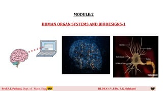
  • 1. 1 MODULE:2 HUMAN ORGAN SYSTEMS AND BIODESIGNS-1 Prof.P.L.Puthani, Dept. of . Mech. Engg BLDEA’s V.P.Dr. P.G.Halakatti
  • 2. 2 Prof.P.L.Puthani, Dept. of . Mech. Engg BLDEA’s V.P.Dr. P.G.Halakatti
  • 3. 3 Prof.P.L.Puthani, Dept. of . Mech. Engg BLDEA’s V.P.Dr. P.G.Halakatti 2.1 Brain as a CPU System Brain is highly sophisticated & complex information processing system, similar to a CPU. Both Brain & CPU receive & process inputs, store information & perform calculations to produce outputs. Way of storing & processing of information in both of them are different.
  • 4. 4 Prof.P.L.Puthani, Dept. of . Mech. Engg BLDEA’s V.P.Dr. P.G.Halakatti Comparison Chart Basis for Comparison Brain Computer Construction Neurons & synapses ICs, transistors, diodes, capacitors, transistors, etc. Memory growth Increases each time by connecting synaptic links Increases by adding more memory chips Backup systems Built-in backup system Backup system is constructed Manually Memory power 100 teraflops (100 trillion calculations/seconds) 100 million megabytes Memory density 107 circuits/cm3 1014 bits/cm3 Energy consumption 12 watts Gigawatts Information storage Stored in electrochemical & electric impulses. Stored in numeric & symbolic form (binary bits).
  • 5. 5 Prof.P.L.Puthani, Dept. of . Mech. Engg BLDEA’s V.P.Dr. P.G.Halakatti Comparison Chart continued Basis for Comparison Brain Computer Size and weight Volume = 1500 cm3 & weight ≈ 3.3 pounds. Variable weight and size form few grams to tons. Transmission of information Uses chemicals to fire the action potential in the neurons. Communication is achieved through electrical coded signals. Information processing power Low High Input/output equipment Sensory organs Keyboards, mouse, web cameras, etc. Structural organization Self-organized Pre-programmed structure Parallelism Massive Limited Reliability and damageability Properties Brain is self-organizing, self maintaining and reliable. Computers perform a monotonous job and can't correct itself.
  • 6. 6 Prof.P.L.Puthani, Dept. of . Mech. Engg BLDEA’s V.P.Dr. P.G.Halakatti Architecture
  • 7. 7 Prof.P.L.Puthani, Dept. of . Mech. Engg BLDEA’s V.P.Dr. P.G.Halakatti Prefrontal Cortex functions as similar to ALU. Higher-level cognitive functions such as decision making & problem solving are identified by prefrontal cortex. Information is stored in memory units of CPU. Human brain has several regions dedicated to memory storage, including the hippocampus & amygdala.
  • 8. 8 Prof.P.L.Puthani, Dept. of . Mech. Engg BLDEA’s V.P.Dr. P.G.Halakatti CNS (Central Nervous System ) and PNS (Peripheral Nervous System)
  • 9. 9 Prof.P.L.Puthani, Dept. of . Mech. Engg BLDEA’s V.P.Dr. P.G.Halakatti Central Nervous System • Consists of brain & spinal cord • Receives, processes & integrates sensory information and transmit commands to the rest of the body. • Brain acts as the command center, receives & processes sensory inputs and generates motor outputs. • Spinal cord acts as a relay center, transmitting information between the brain and peripheral nerves. Peripheral Nervous System • Located outside the brain and spinal cord • Transmits sensory information from the periphery of the body (such as the skin, muscles & organs) to the CNS, and transmits commands from the CNS to the periphery. • PNS can be further divided into the somatic nervous system (Voluntary movements) and the autonomic nervous system (Involuntary i.e heart rate, digestion, respiration)
  • 10. 10 Prof.P.L.Puthani, Dept. of . Mech. Engg BLDEA’s V.P.Dr. P.G.Halakatti Signal Transmission Occurs through the firing of nerve cells or neurons known as Synaptic transmission. Information transferred through Dendrites by generating electric impulse down to Axons & Synaptic terminals. Postsynaptic neurons & the balance of neurotransmitter levels can influence brain function, including mood, learning & memory. Influenced by various forms of synaptic plasticity, including Long-term Potentiation (LTP) and Long-term Depression (LTD).
  • 11. 11 Prof.P.L.Puthani, Dept. of . Mech. Engg BLDEA’s V.P.Dr. P.G.Halakatti Neuron Neuro Transmitter
  • 12. 12 Prof.P.L.Puthani, Dept. of . Mech. Engg BLDEA’s V.P.Dr. P.G.Halakatti EEG (Electro Encephalo Graphy) Non-invasive method for measuring the electrical activity of the brain. Records the electrical signals generated by the brain‘s neurons as they communicate with each other. Signals are recorded through electrodes placed on the scalp and the resulting EEG pattern provides information about the synchronized electrical activity of large population of neurons
  • 13. 13 Prof.P.L.Puthani, Dept. of . Mech. Engg BLDEA’s V.P.Dr. P.G.Halakatti EEG Applications Diagnosis of Epilepsy (Abnornal activity in brain) Sleep Studies (Sleep Pattern) Brain-Computer Interfaces (BCI) {Prosthetics Limbs} Research on Brain Function (Reading, Problem-Solving) Diagnosis of Brain Disorders (Dementia,Parkinson’s Dis., Traumatic brain injury) Anesthesia Monitoring (During Surgery- Safe and Comfortable state) Monitoring Brain Activity during Coma (Level of brain function)
  • 14. 14 Prof.P.L.Puthani, Dept. of . Mech. Engg BLDEA’s V.P.Dr. P.G.Halakatti EEG Signals and Types of Brain Activity
  • 15. 15 Prof.P.L.Puthani, Dept. of . Mech. Engg BLDEA’s V.P.Dr. P.G.Halakatti Robotic Arms for Prosthetics Advanced prosthetic devices use robotics technology to restore functionality of individuals with upper limb amputations. Consists of motors, actuators & sensors to mimic the movements of a human arm & hand, allowing the wearer to perform tasks such as reaching, grasping & manipulating objects. Direct control through muscle signals (myoelectric control) or brain-machine interfaces, which use electrodes implanted in the brain or placed on the scalp to detect and interpret brain activity.
  • 16. 16 Prof.P.L.Puthani, Dept. of . Mech. Engg BLDEA’s V.P.Dr. P.G.Halakatti Robotic Arm Prosthetic Direct Control through Muscle Signals (Myoelectric Control)  Electrical signals generated by the wearer's remaining muscles control the movement of the prosthetic. Electrodes placed on the skin over the remaining muscle are used to detect & interpret the electrical signals generated by the muscle contractions. Advantage of being directly controlled by the user, allowing for a more intuitive & natural interaction with the prosthetic. High level of control & precision, as the electrical signals are unique to each individual perform a wide range of movements.
  • 17. 17 Prof.P.L.Puthani, Dept. of . Mech. Engg BLDEA’s V.P.Dr. P.G.Halakatti Myoelectric control systems can be complex and may require extensive rehabilitation and training to use effectively. Maintenance needed to ensure proper function. Additionally, the system may not be suitable for individuals with muscle weakness or other conditions that affect the ability to generate strong electrical signals.
  • 18. 18 Prof.P.L.Puthani, Dept. of . Mech. Engg BLDEA’s V.P.Dr. P.G.Halakatti Robotic Arm Prosthetic by Brain-Machine Interfaces (BMI)
  • 19. 19 Prof.P.L.Puthani, Dept. of . Mech. Engg BLDEA’s V.P.Dr. P.G.Halakatti Robotic Arm Prosthetic by Brain-Machine Interfaces (BMI) cont. A technology that allows user to control a robotic arm prosthetic directly with their brain activity. Electrodes are placed on the scalp to detect user's brain signals.  When the user thinks about moving the prosthetic arm,  Brain activity is detected & signals are sent to a control unit, which uses algorithms to interpret the signals & control the movement of the prosthetic. User can control the movement of the prosthetic in real-time by thinking about the desired movement.
  • 20. 20 Prof.P.L.Puthani, Dept. of . Mech. Engg BLDEA’s V.P.Dr. P.G.Halakatti Robotic Arm Prosthetic by Brain-Machine Interfaces (BMI) cont. Advantage of providing a direct & intuitive connection between the user's brain & the prosthetic. High level of control and precision. Sensory feedback to the user, to experience the sensation of touch. BMIs can be complex & invasive systems, require surgical implantation & ongoing maintenance to ensure proper function. Unsuitable for individuals with conditions that affect brain activity or unable to generate strong enough brain signals to control the prosthetic effectively. Ongoing research & development is aimed at improving the performance & accessibility of BMIs, as well as increasing their ease of use and reliability.
  • 21. 21 Prof.P.L.Puthani, Dept. of . Mech. Engg BLDEA’s V.P.Dr. P.G.Halakatti Engineering Solutions for Parkinson’s Disease Neurodegenerative disorder that affects movement & motor function. Several engineering solutions aimed at improving the quality of life. Deep Brain Stimulation (DBS): involves the implantation of electrodes into specific regions of the brain to deliver electrical stimulation which help to relieve tremors, stiffness & difficulty with movement. Exoskeletons: wearable devices that provide support & assistance for individuals with mobility issues to improve balance, reduce tremors & increase overall mobility. Telerehabilitation: telecommunication technology to provide physical therapy & rehabilitation services to individuals.
  • 22. 22 Prof.P.L.Puthani, Dept. of . Mech. Engg BLDEA’s V.P.Dr. P.G.Halakatti Smartwatch Applications: monitor symptoms of Parkinson's disease, such as tremors & provide reminders and prompts for medication & exercise. Virtual Reality: Rehabilitation and therapy for individuals with Parkinson's disease, providing interactive and engaging environments for patients to practice movements, improve coordination and balance. Technologies are not a cure for Parkinson's disease and should be used in conjunction with other forms of treatment and care.
  • 23. 23 Prof.P.L.Puthani, Dept. of . Mech. Engg BLDEA’s V.P.Dr. P.G.Halakatti Artificial Brain Known as an Artificial General Intelligence (AGI) or a synthetic brain. Hypothetical machine with cognitive abilities similar to those of a human brain  Machine that can learn, reason & solve problems in the same way that humans do.  Technical, ethical & philosophical challenges need to be addressed. Artificial Intelligence (AI) systems are designed to perform specific tasks such as image recognition, speech recognition or decision making. Exciting and rapidly advancing field of research that has the potential to change the world in many ways
  • 24. 24 Prof.P.L.Puthani, Dept. of . Mech. Engg BLDEA’s V.P.Dr. P.G.Halakatti Eye as a Camera System
  • 25. 25 Prof.P.L.Puthani, Dept. of . Mech. Engg BLDEA’s V.P.Dr. P.G.Halakatti • Both the eye and a camera capture light and convert it into an image. Main components of the eye •Cornea: Transparent outer layer of the eye functions like a camera lens, bending light to focus it onto the retina. •Iris: Diaphragm in a camera, controlling the amount of light that enters the eye. •Pupil: Aperture in a camera, adjusting the size to control the amount of light entering the eye. •Retina: Camera film or sensor, capturing the light and converting it into electrical signals that are sent to the brain. •Optic Nerve: Cable connecting the camera to a computer, transmitting the electrical signals from the retina to the brain.
  • 26. 26 Prof.P.L.Puthani, Dept. of . Mech. Engg BLDEA’s V.P.Dr. P.G.Halakatti
  • 27. 27 Prof.P.L.Puthani, Dept. of . Mech. Engg BLDEA’s V.P.Dr. P.G.Halakatti  In both the eye and a camera, the captured light is transformed into an image by the lens and the light-sensitive component.  The eye processes the image further, allowing for visual perception, while a camera stores the image for later use.  Eye is much more complex than a camera and has several additional functions, such as adjusting for different levels of light and adjusting focus, that are not found in a camera.  Ability to perceive depth and color, as well as adjust to movements and provide a continuous, real-time image to the brain.
  • 28. 28 Prof.P.L.Puthani, Dept. of . Mech. Engg BLDEA’s V.P.Dr. P.G.Halakatti Architecture of Rod and Cone Cells Rod Cells •Photoreceptor cells in the retina of the eye that are responsible for detecting light and transmitting signals to the brain for the perception of vision, especially in low light conditions. •Contain a protein called rhodopsin that absorbs light and triggers a chain of events leading to the activation of neural signals. • Rods are more sensitive to light than cone cells but do not distinguish color as well.
  • 29. 29 Prof.P.L.Puthani, Dept. of . Mech. Engg BLDEA’s V.P.Dr. P.G.Halakatti Cone Cells •Photoreceptor cells in the retina of the eye that are responsible for color vision and visual acuity (sharpness of vision). •Three types of cone cells, each containing a different photopigment sensitive to different wavelengths of light (red, green, and blue), which allow for the perception of color. •Cones are less sensitive to light than rod cells but provide better visual acuity and color discrimination. •They are concentrated in the fovea, the central part of the retina responsible for detailed and sharp vision.
  • 30. 30 Prof.P.L.Puthani, Dept. of . Mech. Engg BLDEA’s V.P.Dr. P.G.Halakatti Architecture • Rod and cone cells have a similar basic structure, but there are some differences that are crucial for their different functions. • Both types of cells have a photoreceptor outer segment that contains the photopigment (rhodopsin in rods and photopigments in cones) that absorbs light and triggers a change in membrane potential. • Inner segment contains the cell's organelles, including the nucleus and mitochondria.
  • 31. 31 Prof.P.L.Puthani, Dept. of . Mech. Engg BLDEA’s V.P.Dr. P.G.Halakatti  Major difference between rod and cone cells is their shape.  Rod cells are elongated and cylindrical, while cone cells are shorter and more conical in shape. This difference in shape affects the distribution of photopigments and the number of synaptic contacts with bipolar and ganglion cells, which transmit the signals to the brain.  Rod cells have a single long outer segment, while cone cells have several shorter segments.  Rod cells make synapses with one bipolar cell, while cone cells synapse with one of several bipolar cells
  • 32. 32 Prof.P.L.Puthani, Dept. of . Mech. Engg BLDEA’s V.P.Dr. P.G.Halakatti Optical Corrections • Devices or techniques used to improve or correct vision problems caused by a refractive error in the eye. • Refractive errors occur when light entering the eye is not properly focused on the retina, leading to blurred vision. There are several types of refractive errors, 1) Myopia (nearsightedness): Light is focused in front of the retina, making distant objects appear blurry. 2) Hyperopia (farsightedness): Light is focused behind the retina, making near objects appear blurry. 3) Astigmatism: Light is not focused evenly on the retina, leading to blurred or distorted vision.
  • 33. 33 Prof.P.L.Puthani, Dept. of . Mech. Engg BLDEA’s V.P.Dr. P.G.Halakatti Most common optical corrections include: • Eyeglasses: Glasses with corrective lenses can be used to refocus light onto the retina, improving vision. • Contact lenses: Corrective lenses in the form of contacts sit directly on the cornea and work similarly to eyeglasses. • Refractive surgery: Surgicals LASIK (Laser-Assisted In Situ Keratomileusis) and PRK (Photorefractive keratectomy), can reshape the cornea to correct refractive errors. Optical corrections can greatly improve visual acuity and quality of life for people with refractive errors. However, it is important to have regular eye exams to determine the appropriate correction and monitor eye health.
  • 34. 34 Prof.P.L.Puthani, Dept. of . Mech. Engg BLDEA’s V.P.Dr. P.G.Halakatti Cataract • Clouding of the lens of the eye that affects vision. •The lens, located behind the iris and pupil, normally allows light to pass through to the retina and produces clear, sharp images. • However, as we age or due to other factors, the proteins in the lens can clump together and cause the lens to become opaque, leading to vision problems.
  • 35. 35 Prof.P.L.Puthani, Dept. of . Mech. Engg BLDEA’s V.P.Dr. P.G.Halakatti • Symptoms of a cataract include blurred or hazy vision, increased sensitivity to glare and bright lights, faded or yellowed colors, and double vision in one eye. • Cataracts can also cause frequent changes in prescription for eyeglasses or contacts. • Cataract surgery is a common and safe procedure to remove the cloudy lens and replace it with an artificial lens. • Most people experience improved vision within a few days after the procedure. • Regular eye exams can help detect cataracts early and prevent vision loss.
  • 36. 36 Prof.P.L.Puthani, Dept. of . Mech. Engg BLDEA’s V.P.Dr. P.G.Halakatti Lens Materials Most common lens materials (Each with its own unique properties and benefits) • Polymethyl methacrylate (PMMA): Plastic that has been used for many years in artificial lenses. It is a durable and affordable material, but does not have the ability to flex and adjust focus like the natural lens. • Silicone: Soft, flexible material that is resistant to cracking and breaking. • Acrylic: Acrylic is a lightweight, clear material that is similar in properties to PMMA. It is often used in foldable (intraocular lenses) IOLs, which can be inserted through a smaller incision. • Hydrophobic acrylic: Acrylic material that has a special surface treatment that helps to reduce glare and halos around lights. • Hydrophilic acrylic: Acrylic material that is designed to be more compatible with the natural fluid in the eye, reducing the risk of vision-threatening complications. Choice of lens material - patient's individual needs, the surgeon's preference, and the potential risks and benefits of each material.
  • 37. 37 Prof.P.L.Puthani, Dept. of . Mech. Engg BLDEA’s V.P.Dr. P.G.Halakatti Bionic Eye or Artificial Eye • Also known as a retinal implant, is a type of prosthetic device that is surgically implanted into the eye to help restore vision to people who have lost their sight due to certain conditions such as retinitis pigmentosa or age-related macular degeneration. • Consists of a camera, a processor, and an electrode array that is attached to the retina. • Camera captures images and sends signals to the processor, which then transmits electrical stimulation to the electrodes in the retina to stimulate the remaining healthy cells and restore vision. •The restored vision is not perfect, but it can help people with vision loss to perform daily tasks more easily and safely.
  • 38. 38 Prof.P.L.Puthani, Dept. of . Mech. Engg BLDEA’s V.P.Dr. P.G.Halakatti Working of Bionic Eye
  • 39. 39 Prof.P.L.Puthani, Dept. of . Mech. Engg BLDEA’s V.P.Dr. P.G.Halakatti • Capturing images with a small camera and transmitting the information to a processing unit that is attached to the eye. • Processing unit then converts the visual information into electrical signals and sends them to an electrode array that is surgically implanted onto the retina. • Electrodes stimulate the remaining healthy cells in the retina, which then sends signals to the brain to create the perception of vision. •The restored vision is not perfect, but it can help people with vision loss to perform daily tasks more easily and safely. • Some bionic eyes only restore basic visual shapes and patterns, while others can provide more detailed vision. • Powered by a battery that is typically implanted behind the ear.
  • 40. 40 Prof.P.L.Puthani, Dept. of . Mech. Engg BLDEA’s V.P.Dr. P.G.Halakatti Materials Used in Bionic Eye • Silicon or other semiconducting materials for the camera & electrode array. • Biocompatible materials for the casing of the device and the electrode array, such as titanium or titanium alloys, to minimize the risk of infection and rejection by the body. • Conductive materials, such as platinum, iridium, or gold, for the electrodes in the array to provide efficient electrical stimulation to the retina. • Polymers, such as silicone or polyimide, for insulation and protection of the electrodes and other components. • Optical materials, such as glass or acrylic, for the lens of the camera. • Biocompatible and flexible materials for the electrical connections between the camera and the processing unit and between the processing unit and the electrode array. •Advanced computer algorithms and machine learning techniques are also used to improve the accuracy and reliability of the bionic eye technology.
  • 41. 41 Prof.P.L.Puthani, Dept. of . Mech. Engg BLDEA’s V.P.Dr. P.G.Halakatti Heart as a Pump System
  • 42. 42 Prof.P.L.Puthani, Dept. of . Mech. Engg BLDEA’s V.P.Dr. P.G.Halakatti Architecture
  • 43. 43 Prof.P.L.Puthani, Dept. of . Mech. Engg BLDEA’s V.P.Dr. P.G.Halakatti  Four chambers: Right atrium, Left atrium, Right ventricle, Left ventricle.  Blood enters the right atrium from the body and is pumped into the right ventricle, which then pumps the blood to the lungs for oxygenation.  Oxygenated blood returns to the heart and enters the left atrium, which pumps the blood into the left ventricle. The left ventricle then pumps the oxygenated blood out to the rest of the body.  Between each chamber, there are one-way valves that ensure the blood flows in the correct direction and prevent backflow.  Surrounded by the pericardium, a sac that contains a small amount of fluid and helps to protect and lubricate the heart as it beats.
  • 44. 44 Prof.P.L.Puthani, Dept. of . Mech. Engg BLDEA’s V.P.Dr. P.G.Halakatti The Heart Beat Heart's pumping action is controlled by a complex network of electrical and chemical signals, which generate the rhythm of the heartbeat.
  • 45. 45 Prof.P.L.Puthani, Dept. of . Mech. Engg BLDEA’s V.P.Dr. P.G.Halakatti •An electrical stimulus is generated in a special part of the heart muscle called the sinus node (SA node). • Small mass of special tissue in the right upper chamber of the heart (right atrium). • In an adult, the sinus node sends out a regular electrical pulse 60 to 100 times per minute. • Electrical pulse travels down through the conduction pathways and causes the heart's lower chambers (ventricles) to contract and pump out blood. • The right and left atria are stimulated first and contract to push blood from the atria into the ventricles. • The ventricles then contract to push blood out into the blood vessels of the body.
  • 46. 46 Prof.P.L.Puthani, Dept. of . Mech. Engg BLDEA’s V.P.Dr. P.G.Halakatti Electrical Signalling – ECG Monitoring and Heart Related Issues
  • 47. 47 Prof.P.L.Puthani, Dept. of . Mech. Engg BLDEA’s V.P.Dr. P.G.Halakatti  Heart's pumping action is controlled by electrical signaling, which generates the rhythm of the heartbeat.  Electrical signaling can be monitored using an electrocardiogram (ECG), which records the electrical activity of the heart and provides important information about the heart's function.  An ECG measures the electrical signals produced by the heart as it beats and generates a trace or waveform that reflects the electrical activity of the heart.  This trace can be used to diagnose heart conditions and monitor the heart's function.
  • 48. 48 Prof.P.L.Puthani, Dept. of . Mech. Engg BLDEA’s V.P.Dr. P.G.Halakatti Some common heart-related issues that can be diagnosed or monitored using an ECG include:  Arrhythmias: Abnormalities in the heart's rhythm or rate can be detected using an ECG.  Heart disease: Changes in the heart's electrical activity can indicate the presence of heart disease, such as coronary artery disease or heart attacks.  Heart attack: Detecting changes in the heart's electrical activity that indicate a lack of blood flow to the heart. Overall, the ECG is a useful tool for diagnosing and monitoring heart- related issues and helps to provide important information about the heart's function and health.
  • 49. 49 Prof.P.L.Puthani, Dept. of . Mech. Engg BLDEA’s V.P.Dr. P.G.Halakatti Reasons for Blockages of Blood Vessels (A)damage (dead heart muscle) caused by a heart attack, (B) shows the coronary artery with plaque buildup and a blood clot.
  • 50. 50 Prof.P.L.Puthani, Dept. of . Mech. Engg BLDEA’s V.P.Dr. P.G.Halakatti Blockages in blood vessels, also known as arterial blockages or atherosclerosis, can occur for several reasons:  High cholesterol levels: Excessive amounts of low-density lipoprotein (LDL) cholesterol in the blood can lead to the formation of plaque in the blood vessels, which can narrow or block them.  High blood pressure: Over time, high blood pressure can cause damage to the blood vessels, leading to the formation of plaque and blockages.  Smoking: Smoking can damage the inner walls of blood vessels and promote the buildup of plaque, leading to blockages.  Diabetes: People with uncontrolled diabetes are at a higher risk of developing blockages in their blood vessels, due to damage to the blood vessels from high levels of glucose.  Age: As people age, the blood vessels can become stiff and less flexible, increasing the risk of blockages.  Genetics: Some people may be predisposed to developing blockages in their blood vessels due to genetic factors.  Poor diet: A diet high in saturated fats, trans fats, and cholesterol can increase the risk of developing blockages in the blood vessels.
  • 51. 51 Prof.P.L.Puthani, Dept. of . Mech. Engg BLDEA’s V.P.Dr. P.G.Halakatti Design of Stents  Stents are small, metal mesh devices that are used to treat blockages in blood vessels.  Typically used in procedures such as angioplasty, where a balloon catheter is used to open up a blocked blood vessel and a stent is placed to keep it open.
  • 52. 52 Prof.P.L.Puthani, Dept. of . Mech. Engg BLDEA’s V.P.Dr. P.G.Halakatti Design of stents can vary depending on the type of stent and the specific medical condition it is used to treat.  Shape: Cylindrical, helical, and spiraled, to match the shape of the blood vessel and provide adequate support.  Material: Stainless steel, cobalt- chromium, and nitinol (a type of metal that is flexible and can return to its original shape after being expanded).  Coating: Coated with different materials to prevent blood clots from forming and reduce the risk of restenosis (recurrent blockage of the blood vessel).  Expansion mechanism: Designed to expand in different ways, such as by balloon inflation or self-expansion, depending on the type of stent and the specific medical condition it is used to treat. Overall, the design of stents plays an important role in their effectiveness and safety. Stents must be designed to provide adequate support to the blood vessel, prevent restenosis, and minimize the risk of complications such as blood clots.
  • 53. 53 Prof.P.L.Puthani, Dept. of . Mech. Engg BLDEA’s V.P.Dr. P.G.Halakatti Pace Makers  Small device that is surgically implanted in the chest to regulate the heartbeat.  It is used to treat heart rhythm disorders, such as bradycardia (a slow heartbeat) or arrhythmias (abnormal heart rhythms), by delivering electrical impulses to the heart to regulate its rhythm.
  • 54. 54 Prof.P.L.Puthani, Dept. of . Mech. Engg BLDEA’s V.P.Dr. P.G.Halakatti The basic design of a pacemaker consists of:  Generator: Main component of the pacemaker and contains a battery and electronic circuitry to generate and control the electrical impulses.  Leads: Thin wires that connect the generator to the heart and carry the electrical impulses from the generator to the heart.  Electrodes: The electrodes are located at the end of the leads and are used to deliver the electrical impulses to the heart.
  • 55. Pacemakers can be designed to work in different ways, including: 55
  • 56. 56  Single-chamber pacemaker: A single-chamber pacemaker delivers electrical impulses to either the right atrium or the right ventricle of the heart to regulate its rhythm.  Dual-chamber pacemaker: A dual-chamber pacemaker delivers electrical impulses to both the right atrium and the right ventricle of the heart to regulate its rhythm.  Biventricular pacemaker: A biventricular pacemaker delivers electrical impulses to both ventricles of the heart to coordinate their contractions and improve heart function in people with heart failure.
  • 57. Uses of high-quality materials and specialized manufacturing processes to ensure their safety and reliability. Materials used in the construction of pacemakers include: • Medical-grade plastics: Polycarbonate, are used to construct the exterior of the device and to provide insulation and protection for the internal components. • Metals: Stainless steel and titanium, are used in the construction of the leads and electrodes to ensure their durability and long-lasting performance. • Electronic components: Microprocessors, batteries, and capacitors, are used to control the delivery of the electrical impulses and to provide power to the device. • Adhesives: Cyanoacrylate and epoxy, are used to secure the components of the device and to provide insulation and protection for the internal components. 57 Construction of a Pacemaker
  • 58.  Medical device that delivers an electric shock to the heart to restore its normal rhythm in cases of cardiac arrest or other life- threatening heart rhythm disorders.  Defibrillators can be external (placed on the chest) or internal (implanted within the body). 58 Defibrillators
  • 59. The basic design of a defibrillator consists of: – Power source: The power source, typically a battery, provides energy to deliver the electric shock to the heart. – Electrodes: The electrodes are placed on the chest and deliver the electric shock to the heart. – Circuitry: The circuitry in the defibrillator controls the delivery of the electric shock, including the timing, strength, and duration of the shock. – Display: A display on the defibrillator provides information about the heart rhythm, battery life, and other relevant information. 59
  • 60. Automated External Defibrillators (AEDs) • External defibrillators, also known as AEDs, are designed for use by laypeople and are commonly found in public places such as airports, shopping centers, and schools. They are relatively simple in design and typically have voice prompts and visual cues to guide the user through the process of delivering the electric shock. Implantable Cardioverter Defibrillators (ICDs), • Internal defibrillators, also known as ICDs, are surgically implanted within the body and are used to treat people with a high risk of sudden cardiac arrest. They are typically more complex in design, including features such as continuous monitoring of the heart rhythm, and automatic delivery of shocks when necessary. 60
  • 61. Materials Used in the construction of defibrillators include: • Medical-grade plastics: Polycarbonate, are used to construct the exterior of the device and to provide insulation and protection for the internal components. • Metals: Stainless steel and titanium, are used in the construction of the leads and electrodes to ensure their durability and long-lasting performance. • Electronic components: Microprocessors, batteries, capacitors, and high-voltage transformers, are used to control the delivery of the electrical impulses and to provide power to the device. • Adhesives: Cyanoacrylate and epoxy, are used to secure the components of the device and to provide insulation and protection for the internal components. 61
  • 62. Artificial Heart 62  Device that is designed to replace the functions of a damaged or failing heart. Temporary measure to support a patient while they are waiting for a heart transplant, or as a permanent solution for people who are not eligible for a heart transplant.
  • 63. 63 Two main types of artificial hearts:  Total artificial heart is a self-contained device that completely replaces the functions of the natural heart. It is used as a bridge to transplant, meaning it provides temporary support to a patient while they are waiting for a heart transplant.  Heart assist devices, Devices that are surgically implanted into the heart and work alongside the natural heart to support its functions. While these devices are still in the early stages of development, they have the potential to greatly improve the survival and well-being of people with heart disease.