
Recommended
Recommended
More Related Content
What's hot
What's hot (20)
Similar to Chlor alkali
Similar to Chlor alkali (20)
Recently uploaded
Recently uploaded (20)
Chlor alkali
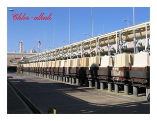
- 1. Chlor-alkali
- 3. Chloralkali process A chlor-alkali plant produces two principle products; chlorine (Cl2) and sodium hydroxide, which is commonly known as caustic soda (NaOH). The term chlor-alkali is derived from the two products produced; chlor from chlorine and alkali from sodium hydroxide (sodium hydroxide is part of a group of chemicals called alkalis). The chlorine and sodium hydroxide are produced from the electrolysis of an aqueous solution of sodium chloride brine (salt water solution). As an alternative, a potassium chloride brine can be used to produce potassium hydroxide, which is commonly known as caustic potash (KOH). Hydrogen gas is produced as a byproduct of the chloralkali process. A typical chlor-alkali plant consists of six main process areas: -brine preparation -electrolysis -chlorine handling -caustic handling -hydrogen handling -hypochlorite In addition to the main process, there are four other plant support areas: -raw material storage and handling -product storage and handling -effluent processing -utilities In the brine preparation section of the plant, an aqueous solution of sodium chloride (NaCl) is prepared and purified. The purified brine is then fed to the electrolytic area, where, in the membrane electrolyzer, chlorine, sodium hydroxide, and hydrogen are produced. Handling and processing of these chemicals depends on the end use of the products. Typically, the chlorine gas is cooled, dried, compressed, liquified and transferred to storage. Sodium hydroxide is often only cooled before being transferred to storage, although it can also be concentrated to higher strengths or converted to a solid form. The byproduct hydrogen gas is either vented to the atmosphere or is cooled and utilized in the production of hydrochloric acid, used as a chemical feedstock to other processes (such as the production of hydrogen peroxide), bottled and sold, or used as fuel in boilers for steam generation. All chlorine containing vents and reliefs in the plant under continuous or emergency duties are processed in a hypochlorite system. The hypochlorite system uses either a sodium hydroxide or calcium hydroxide solution to absorb and react the chlorine to form either sodium or calcium hypochlorite solutions. If a hypochlorite solution is not required, it can be re-processed in the plant.
- 4. Raw Material (Rock salt) storage
- 5. Brine Treatment The main chemical feed to a chloralkali plant is salt, which must be dissolved in water to form a brine solution. However, to obtain long term performance from the electrolyzers it is necessary to produce a brine with very low impurity levels. Calcium, magnesium and sulphate are the major impurities which occur naturally in the raw salt and must be controlled during plant operation. In addition, sodium chlorate is produced to a small extent during electrolysis and must also be controlled. The brine preparation section of the chloralkali plant consists of five process functions. These are: -salt dissolving, -primary brine treatment, -secondary brine treatment, -deionized brine storage, and -weak brine dechlorination. Primary Treatment In the first step of brine preparation, raw salt (sodium chloride) is dissolved in a mixture of warm water and recycled weak dechlorinated brine (from the electrolytic area) to produce a saturated brine solution. The saturated brine solution is then pumped to the primary brine treatment system where most of the calcium and magnesium (dissolved impurities) are removed by chemical precipitation. Soda ash (sodium carbonate) and sodium hydroxide are added to the brine in the primary treatment section and react with the calcium and magnesium to formcarbonate) and sodium hydroxide are added to the brine in the primary treatment section and react with the calcium and magnesium to form insoluble solid precipitates. Demineralized water is also added to adjust the salt content of the brine to a specific concentration. Depending upon the levels of impurities present in the raw salt, the brine is then clarified and filtered. If relatively high quality salt is used, then normally only filtration of the brine is required to remove the solids formed in the primary treatment system. Ion Exchange After filtration, the brine is further processed in the secondary brine treatment system which removes essentially all the remaining calcium and magnesium impurities by ion exchange before being transferred to the purified brine storage tank. The purified brine is then heated and pumped to the electrolyzers where part of the sodium chloride and water are consumed to produce chlorine and sodium hydroxide. After passing through the electrolyzer, the weak or depleted brine solution contains dissolved chlorine gas. Before this weak brine can be re-used in salt dissolving, the dissolved chlorine is removed in two steps. In the first step, hydrochloric acid is added to the brine to reduce the pH which forces some of the chlorine gas out of solution. The remaining dissolved chlorine is first removed by air stripping the brine solution, and then any residual dissolved chlorine is chemically removed by the addition of sodium hydroxide and sodium sulphite in the brine dechlorination step. The concentration of sodium sulphate, which enters with the raw salt, and sodium chlorate, which is produced in small quantities in the electrolytic system, must be controlled to maintain efficient operation of the electrolyzers. Typically a small purge of brine is used to control the level of these impurities. Chemical precipitation of the brine impurities can also be used to control the level of impurities. The weak brine is then recycled back to the salt dissolving system.
- 6. Brine Purification Section Caustic Concentration and Solidification Plant
- 7. Electrolyzer Options Chlorine and sodium hydroxide, as well as the byproduct hydrogen, are produced in the electrolyzers by the electrolysis of an aqueous solution of sodium chloride. Electrolyzers typically consist of an alternating series of anode and cathode plates with a selective semi-permeable membrane between each anode and cathode. Direct current (DC electricity) delivered to the electrolyzer flows from the anode (positive electrode) through the brine in the anode compartment, through the membrane, to the sodium hydroxide in the cathode compartment, and into the cathode (negative electrode). The purified brine flowing through the anode compartment of the electrolyzer is often called the anolyte, because it is the electrically conductive solution passing over the anode. Similarly, the sodium hydroxide flowing through the cathode compartment of the electrolyzer is often called the catholyte, because it is the electrically conductive solution passing over the cathode. Chemical reactions and exchange of materials taking place in a membrane electrolyzer during electrolysis. Purified brine is fed to the anode compartment where chlorine gas is evolved and depleted or weak brine is discharged. Cooled, recycled sodium hydroxide is fed to the cathode compartment where hydrogen gas is evolved and strengthened sodium hydroxide is discharged. The semi-permeable membrane between the anode and cathode selectively permits sodium ions (Na+) and water molecules to pass through the membrane but prevents the diffusion of chloride ions (Cl-) and hydroxyl ions (OH-) through the membrane. As a result, the current efficiency for sodium hydroxide generation is high, and the salt content of the sodium hydroxide solution is very low. The chemical reactions occurring are as follows: 2Na+ + 2Cl- → 2Na+ + Cl2 + 2e- (anode) sodium chloride goes to sodium ions and chlorine 2H+ + 2OH- + 2e- → H2 + 2OH- (cathode) water goes to hydrogen and hydroxyl ions 2NaCl + 2H2O → Cl2 + 2NaOH + H2 (net reaction) sodium chloride and water goes to chlorine, sodium hydroxide and hydrogen The sodium ions that pass through the membrane combine with hydroxyl ions produced at the cathode to form sodium hydroxide. The catholyte system consists of a tank, pump, and heat exchanger in which sodium hydroxide is recirculated through the electrolyzers and bled off as product. From the electrolyzers, hot strengthened sodium hydroxide drains into the catholyte tank. A controlled flow of sodium hydroxide is pumped to the sodium hydroxide product handling system while the rest is recycled to the electrolyzers. The recycled stream is cooled and diluted by the addition of demineralized water and recirculated to the electrolyzers. As discussed in the brine preparation section, weak brine (anolyte) containing dissolved chlorine drains from the electrolyzers to the weak brine tank. Hydrochloric acid is added to the brine to lower the pH and release most of the dissolved chlorine. The brine is then pumped to the brine dechlorination system for further chlorine removal.
- 10. Evaporation and salt separation The decomposition efficiency of the cells being in the range of only 50%, about half of the NaCl charged is in the weak caustic and is recovered by reason of its low solubility in caustic soda solutions after concentration. Hence the weak, about 10 or 12% NaOH solution is evaporated to about 50% NaOH in a double or triple-effect evaporator with salt separators and then passes through a settler and washing filter. The salt so recovered is again made into charging brine. In the evaporators, nickel tubes are generally used to lessen iron contamination. Since the caustic soda liquor from the evaporator contains 50% NaOH, it will dissolve only about 1% NaCl and other sodium salts after cooling. This liquor may be sold, after settling, as liquid caustic soda. Final evaporation The cooled and settled 50% caustic is concentrated in a single effect final evaporator to 70 to75% NaOH. This very strong caustic should be handled in steam-jacketted pipes to prevent solidification. It is run to the finishing pots. Another method of dehydrating 50% caustic utilizes the precipitation of NaOH monohydrate. This monohydrate contains less water than in the original solution. Precipitation is accomplished by the addition of ammonia to the 50% solution. If the 50% caustic is treated with anhydrous ammonia in a counter-current manner, free-flowing anhydrous crystals separate from the resulting aqueous ammonia. The process has to be carried out in pressure vessels.from the resulting aqueous ammonia. The process has to be carried out in pressure vessels. Finishing caustic in pots 50% caustic was one time finished in cast iron direct-fired pots. The heat efficiency is so low that that now it handles only 70 to 75% NaOH. The final temperature is 500 to 6000C and boils off all but about 1% or less of water. These pots are now being replaced by Dowtherm heated evaporators for caustic evaporation above 50%. The hot anhydrous caustic is treated with sulfur to precipitate iron and settled. The molten caustic is pumped out into thin steel drums or into the flaking machine. Special purification of caustic 50% caustic contains impurities like colloidal iron, NaCl and NaClO3. The iron is often removed by treating the caustic with 1% by weight of 300-mesh calcium carbonate and filtering the resulting mixture. The chloride and chlorate may be removed by allowing the 50% caustic to drop down through a column of 50% aqueous ammonia solution. This treatment produces caustic almost as free of chlorides and chlorates as that made by the mercury process. These purification methods give high –grade caustic with less than 1% impurities (anhydrous basis) whilst standard grade contains 2½ to3% impurities (anhydrous basis).
- 11. Caustic Handling The sodium hydroxide or caustic soda produced in the electrolyzers is hot and at a concentration of approximately 32%. As with chlorine handling, the process equipment required for the caustic soda handling system will depend on the end use of the caustic. Typically, the pure (or product) caustic soda is cooled and then transferred to storage tanks for holding prior to delivery to customers. The caustic soda can also be concentrated, usually to 50% in a caustic evaporator. Steam is used to boil the caustic and remove water from the solution under vacuum conditions. If desired, the caustic soda can also be further concentrated to solid flake form. Chlorine Handling The chlorine gas produced in the electrolyzers is hot and saturated with water vapour. The process equipment required for chlorine handling will depend upon the end use of the chlorine gas. The chlorine handling section of a typical chloralkali plant consists of the four process functions. These are: -cooling -drying -compression-compression -liquefaction If the chlorine is to be used in producing hydrochloric acid (HCl), the chlorine usually only needs to be cooled and compressed prior to use in a HCl synthesis unit. After the hot saturated chlorine gas from the electrolyzers is collected above the electrolyzers in a pipe header it is cooled and filtered to remove the bulk of the moisture in the gas and any salt which may have been carried over in the chlorine gas. Condensed water from the cooler is drained to the weak brine system. The remaining moisture is essentially removed in the drying system. The chlorine drying system usually consists of two chlorine drying towers that circulate concentrated sulphuric acid which absorbs moisture from the chlorine gas. Strong sulphuric acid is continually added to the drying system while weak sulphuric acid is bled off and removed from the plant. The dry chlorine gas is then compressed by a sulphuric acid ring compressor. After compression, the chlorine gas is cooled and liquified and then the liquid chlorine is transferred to storage tanks.
- 12. Chlorine Storage Tanks & Freon compressors Liquid Caustic Storage Tanks
- 13. The most common chloralkali process involves the electrolysis of aqueous sodium chloride (a brine) in a membrane cell. Saturated brine is passed into the first chamber of the cell where the chloride ions are oxidised at the anode to chlorine: 2Cl– → Cl2 + 2e– At the cathode hydrogen in the water is reduced to hydrogen gas, releasing hydroxide ions into the solution: 2H2O + 2e– → H2 + 2OH– The non-permeable ion exchange membrane at the center of the cell allows the sodium ions (Na+) to pass to the second chamber where they react with the hydroxide ions to produce caustic soda (NaOH). The overall reaction for the electrolysis of brine is thus: 2NaCl + 2H2O → Cl2 + H2 + 2NaOH A membrane cell is used to prevent the reaction between the chlorine and hydroxide ions. If this reaction were to occur the chlorine would be disproportionated to form chloride and hypochlorite ions:the chlorine would be disproportionated to form chloride and hypochlorite ions: Cl2 + 2OH– → Cl– + ClO– + H2O At higher temperatures, 333K, chlorate can be formed: 3Cl2 + 6OH– → 5Cl– + ClO3 – + H2O Because of the corrosive nature of the chlorine produced, the anode has to be made from an non-reactive metal such as titanium, whereas the cathode can be made from steel. In the membrane cell, the anode and cathode are separated by an ion-permeable membrane. Saturated brine is fed to the compartment with the anode (the anolyte). Direct current (D.C.) is passed through the cell and the NaCl splits into its constituent components. The membrane passes Na+ ions to the cathode compartment (catholyte), where it forms sodium hydroxide in solution. The chloride ions are oxidised to chlorine gas at the anode, which is collected, purified and stored. Hydrogen gas and Hydroxide ions are formed at the cathode.
- 15. Diaphragm cell In the diaphragm cell process, there are two compartments separated by a permeable diaphragm, often made of asbestos fibers. Brine is introduced into the anode compartment and flows into the cathode compartment. Similarly to the Membrane Cell, chloride ions are oxidized at the anode to produce chlorine, and at the cathode, water is split into caustic soda and hydrogen. The diaphragm prevents the reaction of the caustic soda with the chlorine. A diluted caustic brine leaves the cell. The caustic soda must usually be concentrated to 50% and the salt removed. This is done using an evaporative process with about three tonnes of steam per tonne of caustic soda. The salt separated from the caustic brine can be used to saturate diluted brine. The chlorine contains oxygen and must often be purified by liquefaction and evaporation.
- 16. Mercury cell In the mercury-cell process, also known as the Castner-Kellner process, a saturated brine solution floats on top of the cathode which is a thin layer of mercury. Chlorine is produced at the anode, and sodium is produced at the cathode where it forms a sodium-mercury amalgam with the mercury. The amalgam is continuously drawn out of the cell and reacted with water which decomposes the amalgam into sodium hydroxide and mercury. The mercury is recycled into the electrolytic cell. Mercury cells are being phased out due to concerns about mercury poisoning from mercury cell pollution. Metallic Sodium at the mercury cathode side is kept in continuous flow. Depleted brine saturated with Cl2 overflows from the outlet end of the cell and flows by gravity to the depleted brine receiver. The cell is operated under a slight negative pressure in order to withdraw Cl2 gas to the processing system by a chlorine blower. Metallic Na amalgamates with the flowing Hg cathode and leaves the cell through a weir seal entering into the outlet end box. From the end box the amalgam flows by gravity to the decomposer.end box. From the end box the amalgam flows by gravity to the decomposer. Cell Reaction: Anodic : Cl- -------------> ½ Cl2 + e Cathodic: Na + +x Hg + e --------------> NaHgx Mercury – Sodium amalgam enters the decomposer. Decomposer is a short circuited primary cell in which the sodium amalgam is the soluble anode and the graphite is the insoluble cathode in an electrolyte of sodium hydroxide. Decomposer Reaction: 2Na(Hg)x --------------------> 2Na+ + x Hg + 2e 2H2O + 2e -------------------> 2OH- + H2 2Na(Hg)x + 2H2O ------------> 2NaOH + H2 + xHg
- 17. Mercury cells Schematic of a mercury cell
- 18. Chlorine cooling and drying Chlorine gas exiting the cell line must be cooled and dried since the exit gas can be over 80 °C (176 °F) and contains moisture that allows chlorine gas to be corrosive to iron piping. Cooling the gas allows for a large amount of moisture from the brine to condense out of the gas stream. This reduces both the cooling requirements and feed flow of sulfuric acid required in the drying towers. Cooling also improves the efficiency of both the compression and the liquefaction stage that follows. Chlorine exiting is ideally between 18 °C (64 °F) and 25 °C (77 °F). After cooling the gas stream passes through a series of towers with counter flowing sulfuric acid. The sulfuric acid is fed into the final tower at 98% and the first tower typically has a strength between 66% and 76% depending on materials of construction. These towers progressively remove any remaining moisture from the chlorine gas. After exiting the drying towers the chlorine is filtered to remove any remaining sulfuric acid. Compression and liquefaction Several methods of compression may be used: liquid ring, reciprocating, or centrifugal. The chlorine gas is compressed at this stage and may be further cooled by inter- and after-coolers. After compression it flows to the liquefiers, where it is cooled enough to liquefy. Non condensable gases and remaining chlorine gas are vented off as part of the pressureis cooled enough to liquefy. Non condensable gases and remaining chlorine gas are vented off as part of the pressure control of the liquefaction systems. These gases are routed to a gas scrubber, producing sodium hypochlorite, or used in the production of hydrochloric acid (by combustion with hydrogen) or ethylene dichloride (by reaction with ethylene). Storage and loading Liquid chlorine is typically gravity-fed to storage tanks. It can be loaded into rail or road tankers via pumps or padded with compressed dry gas. Hydrogen handling Hydrogen produced may be vented unprocessed directly to the atmosphere or cooled, compressed and dried for use in other processes on site or sold to a customer via pipeline, cylinders or trucks. Some possible uses include the manufacture of hydrochloric acid or hydrogen peroxide, as well as desulfurization of petroleum oils, or use as a fuel in boilers or fuel cells.
- 19. Chlorine processing, storage and handling Generally, before the chlorine can be used, it goes through a series of processes for cooling, cleaning, drying, compression and liquefaction. The chlorine process usually takes hot, wet cell gas and converts it to a cold, dry gas. Chlorine gas exiting the cell line must be cooled and dried since the exit gas can be over 80 °C (176 °F) and saturated with water that allows chlorine gas to be corrosive to iron piping. Cooling In the primary cooling process, the total volume of gas to be handled is reduced and a large amount of moisture is condensed. Cooling is accomplished in one or several stages with water, brine or other fluids. Care is taken to avoid excessive cooling because, at around 10 ºC, chlorine can combine with water to form a solid material known as chlorine hydrate (Cl2·n H2O; n = 7–8). Maintaining temperatures above 15°C prevents blockages in the process equipment Two methods are most frequently used to cool chlorine gas. One method is indirect cooling through a titanium surface (usually in a single-pass vertical shell-and-tube heat exchanger). The resultant condensate is either fed back into the brine system of the mercury or membrane cell techniqueexchanger). The resultant condensate is either fed back into the brine system of the mercury or membrane cell technique or is dechlorinated by evaporation in the case of the diaphragm cell technique. This method causes less chlorine to be condensed or absorbed and generates less chlorine-saturated water for disposal. Indirect cooling can be carried out in once-through, open-recirculating, or closed-loop systems. Another method is direct cooling with water (or brine or other fluids). The chlorine gas is cooled by passing it directly into the bottom of a tower. Water is sprayed from the top and flows countercurrently to the chlorine. The cooling water is generally free of traces of ammonium salts, to avoid the formation of nitrogen trichloride. This method has the advantage of better mass transfer characteristics and higher thermal efficiencies. Direct cooling is usually carried out in closed-loop systems. Cleaning of wet chlorine Following primary cooling, water droplets and impurities such as brine mist are removed mechanically by using special filters with glass wool fillings or porous quartz granules, or by means of an electrostatic precipitator. Chlorine is then passed to the drying towers.
- 20. Drying Chlorine from the cooling system is more or less saturated with water vapour. The water content is typically 1–3 vol-%. This must be reduced in order to avoid downstream corrosion and to minimise the formation of hydrates The drying of chlorine is carried out almost exclusively with concentrated sulphuric acid (96–98 wt-%) in countercurrent contact towers in two to six stages, which reduce the moisture content to less than 20 mg/m3. The remaining moisture content depends on the temperature and concentration of the sulphuric acid in the last drying stage. For low temperature liquefaction, a lower moisture content is required, which can be achieved by adding more equilibrium stages to the drying towers or by using molecular sieves to levels of 3–9 mg/m3 .The number of stages is usually increased to lower the final strength of the spent sulphuric acid. For example, three stages are needed to reach a spent acid concentration of 50–65 wt-% while six stages are needed for a final concentration of 30–40 wt-%. The columns contain plastic packing resistant to chlorine and sulphuric acid to improve fluids distribution, increase efficiency and lower pressure drops, and thus reduce energy consumption. The heat liberated during dilution of the circulating acid is removed by titanium heat exchangers, and the spent acid is dechlorinated chemically or by stripping. The concentration of the spent acid depends on the number of drying stages and the further potential use or method of disposal. In some cases, the acid is reconcentrated to 96 wt-% by heating it under vacuum and then it is subsequently recirculated. Sometimes the acid is sold or used for other purposes. Rarely, it becomes waste.Rarely, it becomes waste. Cleaning of dry chlorine When leaving the top of the drying tower, dry chlorine passes through high efficiency demisters or a packed bed to prevent the entrainment of sulphuric acid droplets. Compression After drying and cleaning, chlorine gas may be compressed by a variety of compressors, depending on the throughput and the desired pressure: Rotary compressors, such as: sulphuric acid liquid ring compressors for throughputs of 150 t/d per compressor and for pressures of 4 bar or, in two- stage compressors, 12 bar; screw compressors for low throughputs and for pressures of up to 16 bar. Reciprocating compressors, such as: dry ring compressors for throughputs of 200 t/d per compressor and for pressures of up to 16 bar. Centrifugal compressors, such as: turbo compressors in mono- or multi-stage operation for throughputs of up to ~ 1 800 t/d per unit and for pressures of up to 16 bar;
- 21. Because of heat build-up from compression, multi-stage units with coolers between stages are usually necessary. Compressor seals are generally fitted with a pressurised purge to inhibit the leakage of chlorine to the atmosphere. Dry chlorine at high temperatures can react spontaneously and uncontrollably with iron. Chlorine temperatures are therefore usually kept below 120 °C. Liquefaction Liquefaction can be accomplished at different pressure and temperature levels: at ambient temperature and high pressure (for example 18ºC and 7–12 bar), at low temperature and low pressure (for example -35 ºC and 1 bar) or any other intermediate combination of temperature and pressure. Important factors for selecting appropriate liquefaction conditions include the composition of the chlorine gas, the desired purity of the liquid chlorine and the desired yield. Increasing the liquefaction pressure increases the energy consumption of compression, although the necessary energy for cooling decreases, resulting in an overall reduction in energy consumption. The liquefaction yield is typically limited to 90–95 % in a single-stage installation, as hydrogen is concentrated in the residual gas and its concentration needs to be kept below the lower explosive limit.residual gas and its concentration needs to be kept below the lower explosive limit. The choice of the refrigerant in a certain stage of the liquefaction depends on the pressure of the chlorine. When the pressure is sufficiently high, water can be used as an indirect refrigerant. When the pressure is relatively low, other refrigerants such as ammonia (indirect cooling) or liquid chlorine (direct cooling) are used. The residual chlorine in the tail gas can be used to produce hypochlorite, iron(III) chloride or hydrochloric acid. The residual chlorine which cannot be vaporised is then led to the chlorine absorption unit. In some cases, it is recovered by an absorption-desorption process with carbon tetrachloride. The latter has the disadvantage of using a toxic substance with a high ozone depletion and global warming potential. Handling and storage Liquefied chlorine is stored at ambient or low temperature. The pressure corresponds to the vapour pressure of the liquefied chlorine at the temperature in the storage tank. Pressure storage at ambient temperatures (~ 7 bar at 20 °C) has advantages of simplicity of operation, ease of visual external inspections, as well as lower energy and investment costs. Low-pressure storage operating around the boiling point of liquid chlorine (-34 °C) requires more complex infrastructure, particular safety measures and higher energy costs.
- 23. Sulphate Removal Demin. Water Chlorine Packing, Filling Vaporization Hypo Product Chlorine Storage Brine Saturation Primary Treatment Secondary Treatment Electrolysis Salt Hydrogen Handling Caustic Storage Chlorine Compressio n Chlorin e Drying HCl Storage Chlorine Liquefaction Caustic Product HCl Product Hypo Production Chlorine Product Sodium Sulphite Hypo Storage HCl Production Caustic Concentratio n Sulphuric Acid Carbon Dioxide To Hypo HC l Sulphuric Acid NaOH NaO Chlor-Alkali Brine Dechlorinatio n DC Rectificatio n AC Power Supply Demineralized Water Storage Hypo Destructio n Chlorate Destruction n HCl NaO H
- 24. Schematic of a diaphragm cell
- 25. Schematic of a membrane cell
- 26. Bleaching Powder Calcium oxy-chloride is the chemical name of bleaching powder. Preparation of Bleaching Powder Passing chlorine gas over dry slaked lime (Ca(OH)2), gives bleaching powder. It consists of a vertical cast-iron tower. The tower is provided with a hopper at the top, two inlets near the base (one for chlorine and other for hot air) and an exit for waste gases near the top. The tower is fitted with eight shelves at different heights each equipped with rotating rakes. The slaked lime is introduced through the hopper and it comes in contact with chlorine, which slowly moves upwards. Bleaching powder is collected inwhich slowly moves upwards. Bleaching powder is collected in a barrel at the base. The chlorine used in the manufacture of bleaching powder should be dilute and the temperature should be maintained below 40oC. The HasenClever plant consists of four cylinder of cast iron. Each cylinder is about 2m to 3m long .Each cylinder is provided with the stirrer to ensure mixing of substances. There is an inlet that is present in the upper most cylinder for Ca(OH)2 . The bottom cylinder has an inlet that is present for Cl2 and outlet at the bottom for the bleaching powder to be accumulated. Each cylinder is connected to the other cylinder by means of pipes. In this process there are cast iron cylinders operating in series with hydrated lime and chlorine being fed counter current to each other. The cylinders are provided with rotating blades and are arranged horizontally one above the other the rotating blades act both as mixed and conveyors of the inside mass. Hydrated lime is charged at one end of the topmost cylinder while chlorine is introduced at the other end of bottom-most cylinder. With the rotation of the blades there is an intimate mixing of chlorine and lime with simultaneous movement of slaked lime counter current to chlorine gas. The chlorinated lime is discharged from the bottom cylinder and the un-reacted chlorine is recovered from the top cylinder and recycled along with the fresh chlorine. The bleaching powder discharged is stored in cast iron drums and wood barrels. To increase the storage life it is mixed with quick lime to yield tropical bleach containing 25% of available chlorine.
- 27. Properties Bleaching powder is a yellowish white powder and smells strongly of chlorine. It is soluble in water. The lime present is always left behind as an insoluble salt. For this reason it is also called chloride of lime. Bleaching powder is oxidised to chlorine when exposed to air. When bleaching powder is treated with excess of dilute acid, chlorine gas is produced. Amount of chlorine gas produced is called available chlorine.Amount of chlorine gas produced is called available chlorine. It is this chlorine that is responsible for the bleaching action of calcium oxy-chloride. Uses Bleaching powder is commonly used for bleaching clothes. It is also used in bleaching wood pulp in the paper industry. It is used to disinfect drinking water. It is used in the manufacture of chloroform (CHCl3), an anaesthetic. It is used as an oxidising agent. It is used to shrink wool.
- 29. Internal View of the Bleaching Powder Plant
- 30. View of the Vacuum Reaction Drum at Bleaching Powder Plant
- 31. Sodium Hypochlorite Plant Sodium hypochlorite also known as liquid bleach is produced by reacting dilute caustic soda solution with chlorine gas under controlled conditions of temperature. Chemical reaction Cl2 + 2NaOH --------- NaOCl +NaCl +H2O
- 32. Calcium hypochlorite is a chemical compound with formula Ca(ClO)2. It is widely used for water treatment and as a bleaching agent (bleaching powder). This chemical is considered to be relatively stable and has greater available chlorine than sodium hypochlorite (liquid bleach). Preparation It is manufactured by the calcium process and the sodium process. The calcium process proceeds as follows: 2 Ca(OH)2 + 2 Cl2 → Ca(ClO)2 + CaCl2 + 2 H2O The sodium process proceeds as follows: 2 Ca(OH)2 + 3 Cl2 + 2 NaOH → Ca(ClO)2 + CaCl2 + 2 H2O + 2 NaCl Bleaching powder is actually a mixture of calcium hypochlorite (Ca(ClO)2) and the basic chloride CaCl2, Ca(OH)2, H2O with some slaked lime, Ca(OH)2. Properties Calcium hypochlorite is a yellow white solid which has a strong smell of chlorine. It is not highly soluble in water, and is more preferably used in soft to medium-hard water. It has two forms: a dry form and a hydrated form. The hydrated form is safer to handle. Calcium hypochlorite reacts with carbon dioxide to form calcium carbonate and release chlorine:Calcium hypochlorite reacts with carbon dioxide to form calcium carbonate and release chlorine: 2 Ca(ClO)2 + 2 CO2 → 2 CaCO3 + 2 Cl2 + O2 Calcium hypochlorite reacts with hydrochloric acid to form calcium chloride: Ca(ClO)2 + 4 HCl → CaCl2 + 2 H2O + 2 Cl2 Uses Calcium hypochlorite is used for the disinfection of drinking water or swimming pool water. It is used as a sanitizer in outdoor swimming pools in combination with a cyanuric acid stabilizer, which reduces the loss of chlorine due to ultraviolet radiation. The calcium content hardens the water and tends to clog up some filters; hence, some products containing calcium hypochlorite also contain anti-scaling agents. Calcium hypochlorite is also an ingredient in bleaching powder, used for bleaching cotton and linen. It is also used in bathroom cleaners, household disinfectant sprays, moss and algae removers, and weedkillers. In addition, calcium hypochlorite may be used to manufacture chloroform. Safety Calcium hypochlorite is best kept in a cool dry place away from any organic material. It is known to undergo self heating and rapid decomposition accompanied by the release of toxic chlorine gas.