
Recommended
More Related Content
Similar to Thyristor Characteristics and Applications
Similar to Thyristor Characteristics and Applications (20)
More from SaifURehmanSidhu
Recently uploaded
Recently uploaded (20)
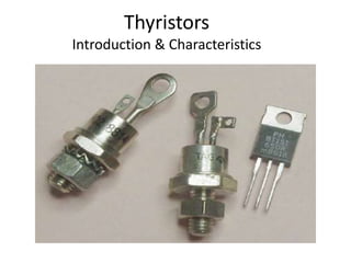
Thyristor Characteristics and Applications
- 2. Power Semiconductor Switches Power Diodes Power Transistors Thyristors 2 layer device 3 layer Device 4 layer Device • Thyristor devices can convert and control large amounts of power in AC or DC systems while using very low power for control. • Thyristor family includes 1- Silicon controlled switch (SCR) 2- Gate-turnoff thyristor (GTO) 3- Triac 4- Diac 5- Silicon controlled switch (SCS) 6- Mos-controlled switch (MCT) 2
- 3. • One of the most important type of power semiconductor device. • Compared to transistors, thyristors have lower on- state conduction losses and higher power handling capability. • However, they have worse switching performances than transistors. Introduction
- 4. • Have the highest power handling capability. • It has a rating of 1200V / 1500A with switching frequencies ranging from 1KHz to 20KHz. • This power can be controlled by a gate current of about 1A only. Cntd…
- 5. Thyristor Family Members • SCR: Silicon Controlled Rectifier • DIAC: Diode on Alternating Current • TRIAC : Triode for Alternating Current • SCS: Silicon Control Switch • SUS: Silicon Unilateral Switch • SBS: Silicon Bidirectional Switch • SIS: Silicon Induction Switch • LASCS: Light Activated Silicon Control Switch • LASCR: Light Activated Silicon Control Rectifier • SITh : Static Induction Thyristor • RCT: Reverse Conducting Thyristor • GTO : Gate Turn-Off thyristor • MCT: MOSFET Controlled Thyristor • ETOs: Emitter Turn ON thyristor
- 6. THYRISTOR • Thyristor, a three terminal, four layers solid state semiconductor device, each layer consisting of alternately N- type or P-type material, i.e; P-N-P-N, that can handle high currents and high voltages, with better switching speed and improved breakdown voltage . • Name ‘thyristor’, is derived by a combination of the capital letters from THYRatron and transISTOR. • Thyristor has characteristics similar to a thyratron tube which is a type of gas filled tube used as a high energy electrical switch and controlled rectifier. • But from the construction view point, a thyristor (pnpn device) belongs to transistor (pnp or npn device) family. • This means that thyristor is a solid state device like a transistor and has characteristics similar to that of a thyratron tube.
- 7. THYRISTORS • Thyristor (famous as Silicon Control Rectifier-SCR) can handle high currents and high voltages. • Thyristor a three terminal (Anode, Cathode and Gate), three junctions and four layers solid-state semiconductor device, with silicon doped alternate material with P-N-P-N structure. • Thyristor act as bistable switches. – It conducts when gate receives a current pulse, and continue to conduct as long as forward biased (till device voltage is not reversed). – They stay ON once they are triggered, and will go OFF only if current is too low or when triggered off.
- 9. Two-Transistor Model of Thyristors • .
- 10. Thyristor- Operation Principle • Thyristor has three p-n junctions (J1, J2, J3 from the anode). • When anode is at a positive potential (VAK) w.r.t cathode with no voltage applied at the gate, junctions J1 & J3 are forward biased, while junction J2 is reverse biased. – As J2 is reverse biased, no conduction takes place, so thyristor is in forward blocking state (OFF state). – Now if VAK (forward voltage) is increased w.r.t cathode, forward leakage current will flow through the device. – When this forward voltage reaches a value of breakdown voltage (VBO) of the thyristor, forward leakage current will reach saturation and reverse biased junction (J2) will have avalanche breakdown and thyristor starts conducting (ON state), known as forward conducting state . • If Cathode is made more positive w.r.t anode, Junction J1 & J3 will be reverse biased and junction J2 will be forward biased. • A small reverse leakage current flows, this state is known as reverse blocking state. • As cathode is made more and more positive, stage is reached when both junctions A & C will be breakdown, this voltage is referd as reverse breakdown voltage (OFF state), and device is in reverse blocking state
- 12. Ideal Characteristic Of SCR 12
- 13. Thyristor Operating modes Thyristors have three modes : Forward blocking mode: Anode is positive w.r.t cathode, but the anode voltage is less than the break over voltage (VBO) . • only leakage current flows, so thyristor is not conducting .
- 14. . Forward conducting mode: When anode voltage becomes greater than VBO, thyristor switches from forward blocking to forward conduction state, a large forward current flows. • If the IG=IG1, thyristor can be turned ON even when anode voltage is less than VBO. – The current must be more than the latching current (IL). – If the current reduced less than the holding current (IH), thyristor switches back to forward blocking state.
- 15. . Reverse blocking mode: When cathode is more positive than anode , small reverse leakage current flows. • However if cathode voltage is increased to reverse breakdown voltage , Avalanche breakdown occurs and large current flows.
- 16. Thyristor turn-ON methods • Thyristor turning ON is also known as Triggering. • With anode positive with respect to cathode, a thyristor can be turned ON by any one of the following techniques : – Forward voltage triggering – Gate triggering – dv/dt triggering – Temperature triggering – Light triggering
- 17. Forward Voltage Triggering • When breakover voltage (VBO) across a thyristor is exceeded than the rated maximum voltage of the device, thyristor turns ON. • At the breakover voltage the value of the thyristor anode current is called the latching current (IL) . • Breakover voltage triggering is not normally used as a triggering method, and most circuit designs attempt to avoid its occurrence.
- 18. Gate Triggering • Turning ON of thyristors by gate triggering is simple and efficient method of firing the forward biased SCRs. • In Gate Triggering, thyristor with forward breakover voltage (VBO), higher than the normal working voltage is chosen. – This means that thyristor will remain in forward blocking state with normal working voltage across anode and cathode with gate open. • Whenever thyristor’s turn-ON is required, a positive gate voltage b/w gate and cathode is applied. • With gate current established, charges are injected into the inner p layer and voltage at which forward breakover occurs is reduced.
- 19. • Forward voltage at which device switches to on-state depends upon the magnitude of gate current. - Higher the gate current, lower is the forward breakover voltage. • When positive gate current is applied, gate P layer is flooded with electrons from cathode, as cathode N layer is heavily doped as compared to gate P layer. • As the thyristor is forward biased, some of these electrons reach junction J2. • As a result, width of depletion layer around junction J2 is reduced. - This causes junction J2 to breakdown at an applied voltage lower than forward breakover voltage VB0. • If magnitude of gate current is increased, more electrons will reach junction J2, thus thyristor will get turned ON at a much lower forward applied voltage.
- 20. 20 SCR Turnoff (Commutation) Circuits
- 21. What is Commutation? The process of turning off an SCR is called commutation. It is achieved by 1. Reducing anode current below holding current 2. Make anode negative with respect to cathode Types of commutation are: 1. Natural or line commutation 2. Forced commutation 21
- 22. ~ T + vo vs R Natural Commutation •Natural commutation Occurs in AC circuits
- 23. t t t t Supply voltage vs Sinusoidal Voltage across SCR Load voltage vo Turn off occurs here 0 0 2 2 3 3 tc Gate Pulse
- 24. SCR Turnoff Methods 1. Diverting the anode current to an alternate path 2. Shorting the SCR from anode to cathode 3. Applying a reverse voltage (by making the cathode positive with respect to the anode) across the SCR 4. Forcing the anode current to zero for a brief period 5. Opening the external path from its anode supply voltage 6. Momentarily reducing supply voltage to zero 24
- 28. The thyristor firing circuit shown in previous slide is similar in design to the DC SCR circuit except for the omission of an additional “OFF” switch and the inclusion of diode D1 which prevents reverse bias being applied to the Gate. During the positive half-cycle of the sinusoidal waveform, the device is forward biased but with switch S1 open, zero gate current is applied to the thyristor and it remains “OFF”. On the negative half-cycle, the device is reverse biased and will remain “OFF” regardless of the condition of switch S1. If switch S1 is closed, at the beginning of each positive half- cycle the thyristor is fully “OFF” but shortly after there will be sufficient positive trigger voltage and therefore current present at the Gate to turn the thyristor and the lamp “ON”.
- 29. The thyristor is now latched-“ON” for the duration of the positive half-cycle and will automatically turn “OFF” again when the positive half-cycle ends and the Anode current falls below the holding current value. During the next negative half-cycle the device is fully “OFF” anyway until the following positive half-cycle when the process repeats itself and the thyristor conducts again as long as the switch is closed. Then in this condition the lamp will receive only half of the available power from the AC source as the thyristor acts like a rectifying diode, and conducts current only during the positive half-cycles when it is forward biased. The thyristor continues to supply half power to the lamp until the switch is opened.
- 30. If it were possible to rapidly turn switch S1 ON and OFF, so that the thyristor received its Gate signal at the “peak” (90o) point of each positive half-cycle, the device would only conduct for one half of the positive half-cycle. In other words, conduction would only take place during one- half of one-half of a sine wave and this condition would cause the lamp to receive “one-fourth” or a quarter of the total power available from the AC source. By accurately varying the timing relationship between the Gate pulse and the positive half-cycle, the Thyristor could be made to supply any percentage of power desired to the load, between 0% and 50%. Obviously, using this circuit configuration it cannot supply more than 50% power to the lamp, because it cannot conduct during the negative half-cycles when it is reverse biased.
- 31. Silicon Controlled Rectifier • Industrially SCRs are applied to produce DC voltages for motors from AC line voltage • Rectifier – Half-wave rectifier, full-wave rectifier
- 35. Half Wave Phase Control
- 36. Phase control is the most common form of thyristor AC power control and a basic AC phase-control circuit can be constructed as shown above. Here the thyristors Gate voltage is derived from the RC charging circuit via the trigger diode, D1. During the positive half-cycle when the thyristor is forward biased, capacitor, C charges up via resistor R1 following the AC supply voltage. The Gate is activated only when the voltage at point A has risen enough to cause the trigger diode D1, to conduct and the capacitor discharges into the Gate of the thyristor turning it “ON”. The time duration in the positive half of the cycle at which conduction starts is controlled by RC time constant set by the variable resistor, R1.
- 37. Increasing the value of R1 has the effect of delaying the triggering voltage and current supplied to the thyristors Gate which in turn causes a lag in the devices conduction time. As a result, the fraction of the half-cycle over which the device conducts can be controlled between 0 and 180o, which means that the average power dissipated by the lamp can be adjusted. However, the thyristor is a unidirectional device so only a maximum of 50% power can be supplied during each positive half-cycle.