This document describes an automatic coded card security system that uses PIR sensors. The system uses coded cards with unique IDs to identify authorized individuals, along with a secret code number. An individual must provide both the correct card and code number to gain entry. The system detects card IDs using a card reader connected to a microcontroller. It also uses PIR sensors to detect movement and trigger alarms if an unauthorized entry is detected. The system provides secure, automated access control.
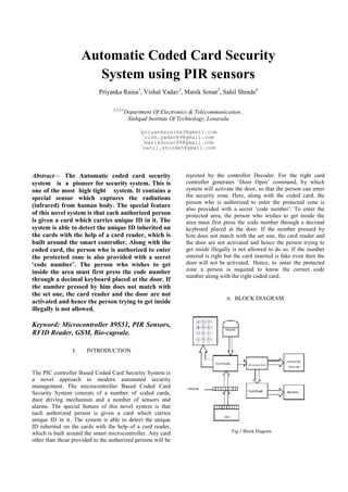
![A. PIR SENSORS
SB0061 is a pyroelectric sensor module which developed
for human body detection. A PIR detector combined with
a fresnel lens are mounted on a compact size PCB
together with an analog IC, SB0061, and limited
components to form the module. High level output of
variable width is provided.
Features and electrical specifications:-
• Compact size (28 x 38 mm)
• Supply current: DC5V-20V(can design DC3V-24V)
• Current drain :< 50uA
• Voltage Output: High/Low level signal :3.3V
• TTL output
• High sensitivity
• Delay time:5s-18 minute
• Blockade time:0.5s-50s (acquiescently 0 seconds)
• Operation temperature:-1500
C-7000
C
Fig.2 Lens Information
B. 89S51 MICROCONTROLLER
The AT89S51 is a low-power, high-performance
CMOS 8-bit microcontroller with 4K bytes of In-System
Programmable Flash memory. The device is manufactured
using Atmel’s high-density non volatile memory
technology and is compatible with the industry standard
80C51 instruction set and pin out. The on-chip Flash
allows the program memory to be reprogrammed in-
system or by a conventional non volatile memory
programmer. By combining a versatile 8-bit CPU with In-
System Programmable Flash on a monolithic chip, the
Atmel AT89S51 is a powerful microcontroller which
provides a highly-flexible and cost-effective solution to
many embedded control applications.
The AT89S51 provides the following standard features:
• 4K bytes of Flash,
• 128 bytes of RAM,
• 32 I/O lines,
• Watchdog timer,
• two data pointers,
• two 16-bit timer/counters,
• on-chip oscillator
C. RFID SENSOR
We can generate IR[Infrared] source using electronic
circuitry in our labs. This circuit is constructed using IC
555, as astable multivibrator. In astable multivibrator
mode the I.C 555 generates continuous pulses. The
amplitude of the pulses will be equal to Vcc voltage. In
this mode the pin no 2 and 6 will be shorted. There will
be a resistor (Ra) connected between pin no.7 & 8,
another resistor (Rb) between pin no.7 to Vcc and a
capacitor (C) from pin no. 6 to ground. The pin no. 4
will be connected to supply point. After feeding the
supply to pin no 1 &8 the output is taken at pin no.3 it
will be a continuous square wave. By varying the values
of Ra, Rb and C the output frequency can be varied.
This frequency is used to driver the IR LED connected
at the at pin no 3. it emits IR rays, as the normal LED
emits light, IR LED emits IR rays. These are not visible
to eye.The frequency range is 20Hz to 455KHz.
D. MAX 232
The MAX232 is a dual driver/receiver that
includes a capacitive voltage generator to supply
TIA/EIA-232-F voltage levels from a single 5-V supply.
Each receiver convert TIA/EIA-232-F inputs to 5-V
TTL/CMOS levels. These receivers have a typical
threshold of 1.3V, a typical hysteresis of 0.5 V, and can
accept ±30-V inputs. Each driver converts TTL/CMOS
input levels into TIA/EIA-232-F levels.The MAX232 was
the first IC which in one package contains the necessary
drivers (two)and receivers (also two), to adapt the RS-232
signal voltage levels to TTL logic. It became popular,
because it just needs one voltage (+5V) and generates the
necessary RS-232 voltage levels (approx. -10V and +10V)
internally. This greatly simplified the design of circuitry.
The MAX232 has a successor, the MAX232A. It should
be noted that the MAX232 (A) is just a driver/receiver. It
does not generate the necessary RS-232 sequence of marks](https://image.slidesharecdn.com/bc796358-7cd5-4247-958c-134ca8878c24-151124000157-lva1-app6891/85/IEEE-PAPER-2-320.jpg)

![REFERENCES
[1] Nakamoto, H.; Yamazaki, D.; Yamamoto, T.;
Kurata, H.; Yamada, S.; Mukaida, K.; Ninomiya, T.;
Ohkawa, T.; Masui, S.; Gotoh, K., "A Passive UHF
RF Identification CMOS Tag IC Using Ferroelectric
RAM in 0.35-µm Technology," Solid-State Circuits,
IEEE Journal of , vol.42, no.1, pp.101-110, Jan. 2007.
[2] Nikitin, P.V.; Rao, K.V.S.,"Theory and measurement
of backscattering from RFID tags," Antennas and
Propagation Magazine, IEEE , vol.48, no.6, pp.212-218,
Dec. 2006.
[3] P. V. Nikitin and K. V. S. Rao, Antennas and
Propagation in UHF RFID Systems, IEEE RFID 2008
conference, Las Vegas, NV, April 2008.
[4] Zhihua Wang; Xuguang Sun; Chun Zhang; Yongming Li,
"Issues in Integrated Circuit Design for UHF
RFID," Radio-Frequency Integration Technology, 2007.
RFIT 007. IEEE International Workshop on , vol., no.,
pp.322-328, 9-11 Dec. 2007.
[5] Xin Jin; Sarkar, S.; Ray, A.; Gupta, S.; Damarla, T.,
"Target Detection and Classification Using Seismic and
PIR Sensors," Sensors Journal, IEEE , vol.12, no.6,
pp.1709,1718, June 2012.
[6] Chang, Kok-Leong; Bah-Hwee Gwee; Yuanjin Zheng, "A
semi-custom memory design for an asynchronous 8051
microcontroller," Circuits and Systems, 2008. ISCAS
2008. IEEE International Symposium on , vol., no.,
pp.3398,3401, 18-21 May 2008.](https://image.slidesharecdn.com/bc796358-7cd5-4247-958c-134ca8878c24-151124000157-lva1-app6891/85/IEEE-PAPER-4-320.jpg)


![[IJET-V1I4P5] Authors :Divya Lakshmi M , Dr. Ramesh R](https://cdn.slidesharecdn.com/ss_thumbnails/ijet-v1i4p5-150728164001-lva1-app6892-thumbnail.jpg?width=640&height=640&fit=bounds)


![5.[26 35] rfid security using mini des algorithm in deployment of bike rentin...](https://cdn.slidesharecdn.com/ss_thumbnails/5-26-35rfidsecurityusingminidesalgorithmindeploymentofbikerentingsystem-111118182703-phpapp02-thumbnail.jpg?width=640&height=640&fit=bounds)
![5.[26 35] rfid security using mini des algorithm in deployment of bike rentin...](https://cdn.slidesharecdn.com/ss_thumbnails/5-26-35rfidsecurityusingminidesalgorithmindeploymentofbikerentingsystem-111118181644-phpapp01-thumbnail.jpg?width=640&height=640&fit=bounds)

![5.[26 35] rfid security using mini des algorithm in deployment of bike rentin...](https://cdn.slidesharecdn.com/ss_thumbnails/5-26-35rfidsecurityusingminidesalgorithmindeploymentofbikerentingsystem-111203185114-phpapp02-thumbnail.jpg?width=640&height=640&fit=bounds)


