The Most Attractive Pune Call Girls Budhwar Peth 8250192130 Will You Miss Thi...
Maintaining_the_Benefit_How_to_Ensure_Mi.pdf
1. Maintaining the Benefit — How to Ensure Mine to Mill Continues
to Work for You
A Dance1
, W Valery2
, A Jankovic3
, D La Rosa4
and S Esen5
ABSTRACT
Metso Minerals Process Technology Asia-Pacific (MMPT-AP) has been
working with many mining companies worldwide performing ‘Mine to
Mill’ or Process Integration and Optimisation (PIO) studies. MMPT-AP
has developed a proven methodology to improve the efficiency of the
mine-mill interface and gain maximum benefit. The PIO methodology
involves rock characterisation, mathematical modelling and simulation to
generate a list of operational and control changes for both the mine and
concentrator.
Following the methodology, the list of recommendations is developed
relatively easily; the more challenging part depends on the company.
Success of a PIO project relies on the ability of an organisation to
implement change – both operationally and culturally: the human
element.
When a PIO project is started, there is initial interest and commitment
from the company. But how can this be maintained? How does an
operation know if the benefit continues? MMPT-AP is now developing
long-term relationships with clients to ensure that the increased
production and improved efficiency continues. Direct and indirect
measurements are used to determine the key factors involved and to
understand the cause/effect relationships. Simulation tools also can be
used to compare current with recommended practices – so when material
properties vary over time, the benefits can still be quantified.
PIO is about empowerment: by measuring and understanding what
parameters affect concentrator performance, the site personnel now have
the knowledge to make a difference. Rather than simply reporting
variable or poor concentrator performance, operations can predict when
production will be affected and put controls in place to prevent it from
happening. This requires support and commitment from the company or
‘buy in’. Ensuring this buy in continues is the challenge facing every
company involved in PIO work – but the benefits are well worth it.
This paper will review MMPT-AP’s experiences in implementing PIO
projects in the long term: from both the consulting and operational
viewpoints. MMPT-AP’s involvement with a number of companies will
be discussed as examples of what works and what does not.
INTRODUCTION
Believe it or not, the term ‘Mine to Mill’ has been used in the
mining industry for over a decade with many operations dabbling
in the concept and resulting in some successes and many failures.
The idea is a simple but effective one: how can the various stages
of the mining process be aware of possible upstream or
downstream issues and work together for greater efficiency? This
typically relates to the mine-mill interface or how the mine can
produce a more suitable, higher value or higher quality
concentrator feed.
Of course, what higher quality mill feed means will vary from
operation to operation. In some cases it is finer fragmentation, in
others it is well blended for grade and lacking in contaminants
and it can even indicate that certain ore types are, in fact, not
profitable and should be considered mineralised waste.
Yet for such a simple concept, the application of Mine to Mill
has proven to be very difficult. The staff members of Metso
Minerals Process Technology Asia-Pacific (MMPT-AP) have
been involved in a significant portion of these efforts either as
MMPT-AP projects or in our former roles as operations and
research engineers. What have we learned over the past decade?
That the issues remain human ones and the engineering
challenges are readily overcome.
MMPT-AP has developed a proven methodology for applying
what we call Process Integration and Optimisation or PIO. PIO
reflects the fact that optimising concentrator feed goes beyond
run-of-mine (ROM) fragmentation and considers all aspects of
improving mill performance from throughput, recovery and final
concentrate grade to lower operating costs.
However, almost all of our clients are focusing their attention
on increased throughput, so the examples included in this paper
reflect that interest.
PIO METHODOLOGY
The methodology involves a number of steps: benchmarking,
rock characterisation, measurements, modelling/simulation and
where required, material tracking. A PIO project is normally
comprised of a number of site visits spaced over a few months.
The first site visit is to establish current operating practice,
initiate rock characterisation and collect measurements of blast
fragmentation and mill performance. This is followed by
modelling and simulation studies to determine how to best
exploit the hidden inefficiencies. These recommendations are
then followed by further site visits to implement the changes,
monitor the results and ensure the improvements are maintained
over time.
Benchmarking and process audits
The first step of a PIO project is to benchmark the current
practices by auditing the operation and control of the blasting,
crushing, grinding and flotation processes.
The quality of blast pattern implementation is assessed and the
resulting ROM fragmentation measured using image analysis.
The crushing, grinding and flotation circuits are surveyed and
process control strategies reviewed. All of these measurements
allow mathematical models to be developed for the complete
process chain. These models are later used to simulate the impact
of operational changes in the mine or concentrator on the entire
process.
Rock characterisation
Once the current operating performance has been measured
under one set of conditions, the effect of changing rock
properties can be quantified. This involves rock characterisation
or defining domains of similar properties. In this paper, this will
be discussed in terms of blast fragmentation. The process could
equally be applied to other quality parameters such as flotation
performance, leach recovery, lump to fines ratio, etc.
Ninth Mill Operators’ Conference Fremantle, WA, 19 - 21 March 2007 1
1. Manager – Process Integration and Optimisation, Metso Minerals
Process Technology Asia-Pacific, Unit 1, 8 - 10 Chapman Place,
Eagle Farm Qld 4009. Email: adrian.dance@metso.com
2. FAusIMM, General Manager, Metso Minerals Process Technology
Asia-Pacific.
3. MAusIMM, Manager – Development and Process Engineering,
Metso Minerals Process Technology Asia-Pacific.
4. Manager – Process Control and Information Engineering, Metso
Minerals Process Technology Asia-Pacific.
5. Crushing Process Technology Engineer, Metso Minerals Process
Technology Asia-Pacific.
2. The MMPT-AP methodology for rock characterisation utilises
simple and inexpensive measurements that can be performed by
trained site personnel. Quite often the measurements are already
being collected by the operation. The advantage of simple
measurements is the amount of data that can be collected in a
very short time frame, as the samples do not require shipping to
an outside laboratory. When attempting to characterise an entire
orebody, the density of data is very important.
For rock characterisation, MMPT-AP use measurements of
rock strength (point load index, PLI and/or UCS) and rock
structure (rock quality designation, RQD and/or fracture
frequency). Both PLI and RQD measurements can be taken on
drill core and point load tests can also be performed on irregular
shaped samples of material.
The PLI value can be correlated to unconfined compressive
strength (UCS) as well as the JKMRC drop weight test
parameters A and b. The drop weight parameters are necessary in
order to model the crushing and grinding circuits. Therefore, the
use of the point load index allows sites to characterise their rock
properties quickly and easily while still making use of the
sophisticated grinding models that are available.
The rock structure is represented by the RQD value that
indicates the fracture frequency present in the drill core. This
measurement is routinely taken at operations for geotechnical
purposes but has been shown to be very useful in blast
fragmentation modelling in the absence of detailed rock mass
structure mapping.
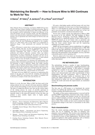
Once the PLI and RQD data are available, the range of rock
properties are mapped out and domains are defined (see
Figure 1). Within each domain, the material will behave similarly
under the same blast conditions while all of the domains cover
the complete range of rock properties that are present.
The domain structure shown in Figure 1 follows the existing
ore type characterisation used by the site but expands further into
areas of structure (coarse, medium and fine) and strength (soft,
medium and hard). The ranges of strength and structure used are
based on the variability of the orebody. The more variable the
PLI and RQD values measured in the orebody, the greater
definition required for domains. In the example given in
Figure 1, the RQD values were divided into ranges of 0 - 30 per
cent, 30 - 60 per cent and >60 per cent while the PLI values were
divided into 0 - 3 MPa, 3 - 6 MPa and >6 MPa.
Once the domains have been defined, different blasting
practices, crushing and milling operational strategies are
established. Through modelling and simulation studies, the
impact of blending different domains can be reviewed. Most
importantly, as the rock properties have now been well
characterised and the processes modelled, the variable nature of
the material can now be compensated for.
Modelling and simulation
The measurements collected while at site are combined with the
rock characterisation domains to model the complete process
chain. MMPT-AP use these data to develop site-specific models
of blast fragmentation, crushing, grinding and flotation. This
allows customised blast patterns to be developed that optimise
both crushing and grinding performance. For each domain, blast
designs are recommended to generate the optimal fragmentation
size for downstream processes. This may involve an increase or
decrease in energy level (or powder factor) depending on the
rock characteristics of each domain.
The objective is to minimise the overall cost for the entire
process by distributing the energy required sensibly and
effectively where it is best applied. Near-field vibration
measurements and models are used to confirm that pit wall
stability issues are considered in the blast designs.
In addition, the crushing and grinding models allow the impact
of operational and control strategies to be investigated. For
example, what is the best closed-side-setting to operate my
primary crusher at in terms of production and product size? What
target load should I use in my SAG mill when processing this
domain? What is the tendency for this material to be SAG mill,
ball mill or recycle crusher limited?
All of these questions can be evaluated using the model of all
the stages of comminution (blasting, crushing and grinding).
BENEFITS OF PIO TO AN OPERATION
It is quite extraordinary how the mining industry has allowed
uncertainty and unpredictability to be an accepted part of normal
operation. It is still common for the concentrator to be unaware
of changes in material properties and how they influence mill
performance. In addition, a lack of accurate material tracking so
that prediction of when these changes will happen is very
unlikely.
This perhaps could be understood before the application of
technologies such as online image analysis, GPS equipment
tracking and sophisticated geological modelling software.
However, these tools are now readily available and can answer so
many outstanding questions: ‘Why is the mill tonnage down?’,
‘How long will it last?’ and more importantly, ‘What can be done
to prevent it in the future?’.
2 Fremantle, WA, 19 - 21 March 2007 Ninth Mill Operators’ Conference
A DANCE et al
Volcanic
Diorite
Intermediate
Tonalite
Young
Tonalite
RQD 0 - 30
RQD 30 - 60
RQD >60
RQD 0 - 30
RQD 30 - 60
RQD >60
RQD 0 - 30
RQD 30 - 60
RQD >60
RQD 0 - 30
RQD 30 - 60
RQD >60
V-FS
V-MM V-MH
V-CM V-CH
D-FS
IT-MH
YT-CH
V-FH
IT-MM
IT-CH
V-CS
D-FM
D-CH
D-CS D-CM
PLI 0 - 3 PLI 3 - 6 PLI >6
FIG 1 - Example of blasting domains (Dance et al, 2006).
3. Time and time again, the explanation of poor performance is
related to ‘bad ore’ without any measurements to back it up. We
as ‘metal manufacturers’ operate in a manner that other
manufacturing sectors could never do – and yet, we still manage
to make a profit (particularly in times of high metal prices).
Imagine the increase in efficiency possible through the
understanding of what material parameters are important to
concentrator performance and the accurate measurement,
tracking and control of those parameters. This is achievable by
every operation worldwide.
Performance improvements
Needless to say, the performance improvements experienced as a
result of PIO projects have been significant; typically, five to
20 per cent increases in throughput through controlled blasting
and crushing practices. In fact, these improvements can occur
without any increase in operating cost but instead, through the
understanding of where to add energy and where to reduce
energy. In one case, the concentrator experienced a throughput
increase of 33 per cent at no added cost.
When finer ROM fragmentation is required through higher-
energy and controlled blasting, quite often the benefits solely in
the mine outweigh any added blasting costs. That is, higher
equipment availability, better digging rates, lower haulage costs,
improved crusher production … the list goes on. With the current
mining and crushing methods, finer material tends to be easier
and cheaper to handle.
Of course, the benefits downstream in the concentrator are
magnified through consistent, high quality feed that leads
to a stable and more predictable performance. In the PIO
methodology discussion above, the definition of blasting
domains allows different blasting and crushing strategies to be
developed. The reason is that SAG and AG mills are no different
from the rod and ball mill circuits operated in the past – all
grinding circuits benefit from consistent and prepared feed
material. After compensating for the harder/softer and blockier/
finer nature of the material, the end product through blasting and
crushing is more consistent – leading to steady and predictable
concentrator performance.
What is the value to an operation to say with confidence: ‘We
know what the mill tonnage will be tomorrow, next week, next
year and until the end of mine life as we can control it.’?
Introduction of measurements
Before concentrator performance can be controlled, the
important material properties affecting mill performance must
first be defined and more importantly, measured. In this paper,
the discussion will focus on mill throughput and be limited to the
effects of material hardness and size. It is very important to
isolate the two as they can often be confused. In addition,
measurement of hardness and size must be done objectively and
if possible, automatically. At one operation, the changes in mill
tonnage observed were related to rock hardness – high tonnage
was ‘soft’ ore and low tonnage was ‘hard’ ore; and of course,
there was nothing that could be done about that. After installing
an online image analysis system and measuring rock hardness
independently, it was determined that hardness had almost no
effect – the changes in mill tonnage were due almost entirely to
feed size. An example of how feed size and the amount of ‘fines’
affected mill tonnage is shown in Figure 2 over a 24-hour period.
It can be seen in Figure 2 that feed size controlled mill
behaviour – more fines, higher tonnage. There was almost no
effect of hardness for this operation. As far as the mill was
concerned, if it was the same size, it processed at the same rate.
Actually measuring material properties – online and
automatically – led to an understanding of what was actually
important. In addition, it provided greater predictability. It was
found that X per cent fines would always lead to Y throughput.
In other words, prepare the feed material and the mill
performance was entirely predictable.
This is very empowering. Instead of a situation where
concentrator performance was changing due to an abstract
hardness factor, it was changing due to material size – that is
entirely under the control of the operation. In other words,
Mother Nature makes the orebody hard or soft, but blasting and
crushing practices make the material big or small. (Stockpile
design and operation can moderate these effects somewhat.) By
knowing how feed size influenced mill performance, it was then
possible to regulate the feed size to achieve the highest possible
mill throughput – every day of the year.
Using MMPT-AP’s PIO methodology detailed above, it is also
possible to predict mill performance until the end of mine life
based on drill core measurements of PLI and RQD with models
of blast fragmentation, crushing and milling circuits linked
together. Such predictions of mill tonnage can be entered into
every ore block of the mine planning software to create a
geometallurgical model.
Methods to monitor and control
As described above, measurements are the key to understanding
what material properties are important to concentrator
performance and in what priority. It is typical that rock
hardness and feed size are the two key parameters affecting
concentrator throughput; however, other factors such as clay
content and specific gravity may also have an effect.
Ninth Mill Operators’ Conference Fremantle, WA, 19 - 21 March 2007 3
MAINTAINING THE BENEFIT — HOW TO ENSURE MINE TO MILL CONTINUES TO WORK FOR YOU
0
10
20
30
40
50
60
0
200
400
600
800
1000
1200
1400
1600
1800
Mill tph
% Coarse
% Medium
% Fines
Weight
%
in
Fraction
Mill
Tonnage
(tph)
FIG 2 - Effect of feed size on SAG mill tonnage (Dance, 2001).
4. Material hardness can be measured in a variety of ways. For
blast domain definition, MMPT-AP relies on point load index
and the ability to correlate the PLI values with drop weight test
parameters. This is very useful for simulation as the models
require estimates of rock strength and breakage characteristics.
For relative comparison, other methods can be used such as
drilling penetration rates and blastability indices. What is
important is that the values used are reproducible and not
subjective (that is, potentially prejudiced or biased).
ROM fragmentation size measurements are now possible using
commercial image analysis systems that have been around for
the past ten years. The strengths and weaknesses of these
systems have been well documented and, provided the user
understands them, the systems provide reliable and accurate
data. (Figure 2 is a good example of applied image analysis
measurements.)
As most operations blend different ore sources in their mill
feed, an understanding of where the material originates is
absolutely essential. This allows the actual concentrator
performance on this material to be reported back into the
geological block model for comparison with any estimates or
prediction of similar material nearby in the future. Material
tracking is a necessity for geometallurgical modelling.
There are currently two methods to track material movements
from the mine to the concentrator: model-based and sacrificial
instruments.
The first method of tracking material involves the development
of a software program to record the movements of material from
the open pit or underground to the intermediate or long-term
stockpiles, through the crusher and coarse ore piles and into the
concentrator. Each stockpile can be represented by simple perfect
mixing models or if necessary, more sophisticated three-
dimensional models.
The models allow the effect of material mixing and delays to
be incorporated and provide a reasonably accurate estimate of
mill feed. Such a system provides much greater definition or
detail on changes in concentrator feed and can be updated as
frequently as every 15 minutes. A daily summary will not
provide such a degree of detail.
Another method for tracking material movements being
employed by MMPT-AP are ore block markers called SmartTags.
MMPT-AP has developed passive radio frequency (RF)
transponders for use in blasted material monitoring. These RF
tags are small, robust and inexpensive and can be dropped into
the blasthole stemming column or placed on the muck pile
surface post-blast (see Figure 3).
The tags are not powered but are detected by antennas placed
over conveyor belts. Each tag has a unique identifying number
that the antenna transmits to a remote computer for recording
along with the date/time. By noting the initial position of each
tag (ie blasthole ID), an estimate of the origin of the material
being processed can be made. By tracking the actual material
itself, concerns about estimating stockpile volumes, mixing and
retention times can be avoided.
Throughput forecasting and geometallurgical
modelling
The measurement and understanding of how rock hardness and
size affect mill performance is needed to optimise ROM material
properties on a daily basis. Operations personnel can adjust the
blast pattern, explosive distribution and primary crusher operation
in order to achieve a consistent feed size to the mill. If necessary,
harder and softer ore types can be blended or campaigned
separately under different grinding circuit operating conditions.
The essential feature of this scenario is the ability to predict
how the material will perform. That includes the situation when
the material was not treated correctly – that is, when tailored
blasting and crushing practices were not followed (as can happen
at times).
The ability to predict concentrator performance under different
operating conditions and well into the future allows different
mine plans to be investigated. For example, what will be the
demand on trucks and shovels if an operation decides to reduce
the blast energy? What will happen over time as the material
properties change? This is the aim of throughput forecasting and
geometallurgical modelling.
After defining representative blasting domains, MMPT-AP
simulate the impact of different rock properties and operating
conditions using the customised models of blasting, crushing and
grinding. Mapping the orebody using rock strength and structure
measurements allows the mill throughput to be simulated as far
into the orebody as the drill core has penetrated. An example of
this is shown in Figure 4.
4 Fremantle, WA, 19 - 21 March 2007 Ninth Mill Operators’ Conference
A DANCE et al
DETECTOR
DETECTOR
[ID,x,y,z]
[ID, time]
RECEPTOR
RECEPTOR
POST BLAST
POST CRUSHER
SAG MILL FEED
[ID, time)
FIG 3 - Use of radio frequency tags to track material movements (Dance et al, 2006).
5. In Figure 4, point load index and RQD values are plotted
against mine elevation. It became very clear that in this case,
rock strength and structure would vary quickly between 800 and
650 m in elevation and then stabilise. In the early stages of the
operation, blasting energy could be minimised but in order to
sustain expected mill throughputs, would need to increase as the
mine deepened. In other words, the initial blast patterns would
not adequately fragment the material to maintain mill tonnage
and adjustments would need to be made. In addition, simulations
indicated that additional mill power would need to be installed in
order to keep the final grind size from coarsening.
The data presented in Figure 4 – along with a detailed mine
plan and blast conditions – can be used to generate a trend of
expected mill throughput and final grind size. This allows
different mine plans and blasting scenarios to be simulated
quickly and easily.
Figure 5 shows an example of throughput forecasting where
daily concentrator tonnages over a three and a half year period
are plotted as blue diamonds. For this operation, throughput
varied from below 4000 tph to over 7000 tph due to a wide range
of ore strengths and structures mapped by PLI and RQD values.
MMPT-AP developed a throughput model based on rock
strength and structure as well as blasting conditions. (In this case,
ore grade was also used to account for hardness variations not
picked up by the PLI results.) Material tracking was necessary in
order to estimate the daily distribution of mill feed from the
different ore sources as well as assign PLI and RQD values to
each source.
Ninth Mill Operators’ Conference Fremantle, WA, 19 - 21 March 2007 5
MAINTAINING THE BENEFIT — HOW TO ENSURE MINE TO MILL CONTINUES TO WORK FOR YOU
20
40
80
100
120
0 100 200 300 400 500 600 700 800 900
0
2
4
6
8
10
12
Point
Load
Index,
Is50
(MPa)
RQD
0
60
Mine Elevation (m)
RQD(%)
RQD
Is50
FIG 4 - Rock strength and structure with mine elevation (Dance et al, 2006).
FIG 5 - Daily throughput predictions including operational envelope.
6. The model predictions are shown in Figure 5 as an upper
and lower ‘operational envelope’. The operational envelope
represents small changes in the input parameters that would
result in higher or lower expected mill tonnage. For example, for
the upper boundary, the rock properties were softened and the
blasting energy increased within an expected variation. The
reverse was done for the lower boundary. Within these expected
variations for normal operation, the predicted concentrator
tonnage varied by 800 tph. Over the three and a half year period,
the average relative error for the model was 0.84 per cent or
±46 tph.
HOW TO ENSURE SUCCESS
Over the past decade, MMPT-AP personnel have been involved
in many Mine to Mill or PIO projects – some successful and
some not. In every case, issues were identified and solutions
presented to the operation that represented significant
improvements in throughput or efficiency. Following a
prescribed methodology, the engineering solutions fall out and
become clear very quickly. Whether or not the operation decides
to implement the recommendations is typically the first hurdle
as, at times, the solutions are a step-change from current
operating practices. The second challenge is sustained
implementation over time. When MMPT-AP has been involved
in successful projects, a number of common traits were in place:
management support and the presence of a site champion,
assistance from an outside agency and ownership of the situation
through changes in key performance indicators.
Site champion and management support
The selection of a site champion is a bit of a misnomer – a true
champion cannot be selected, they must take it upon themselves
to support the project wholeheartedly despite the complaints and
resistance of others. They cannot be told to be the champion.
They must also possess a combination of technical skills (to be
able to explain the benefits) and persuasive skills (in order to
negotiate with the parties involved). It is all about dealing with
cultural change and how the key personnel handle it. The
champion must also have sufficient seniority (or ready access to
seniority) so that they cannot be ignored. An easier option is for
managers to voice their total support of the work and agree
completely with the decisions of the champion. For the work
environment is not a democracy and ultimately whatever the boss
says, goes.
Initial expectations are that if the message is made clear and
the benefits demonstrated, people will decide themselves to
adopt the new practices and support the project. Unfortunately,
this is rarely the case and the voice of senior management
ultimately needs to ring resoundedly in everyone’s ears that
voluntary support is not an option. The economic benefits of PIO
projects can gain the acceptance of senior personnel as they see
more of the ‘big picture’ than others do. However, commitment
or ‘buy in’ from workers on the grinding floor is unlikely unless
financial incentives are put in place (see below).
Outside assistance
Despite the greatest intentions, PIO efforts rarely succeed
without some level of outside assistance or agency. This is
because generally in-house projects do not attract enough
attention from upper management. The advantage of dealing
with a consultancy group experienced in this field is the
confidence their personnel bring with them to site. They have all
done this before and can quickly identify where the benefits can
be made and put systems in place to measure the gains.
You can almost measure the growing level of interest while the
group are at site – and feel the collective sigh of relief when the
consultants depart to generate the report. This is where the
champion comes into play: ‘What can we do straight away based
on the comments and conclusions made by the consultants?’ and
‘Why are we waiting for the report? Why don’t we act
immediately?’
In order to sustain a level of interest at site, regular
maintenance visits need to be scheduled by the outside group.
This is not only to ensure the benefits continue, but also to
motivate people despite the belief that ‘The ore has changed
since you were here last’.
Key performance indicators
To reinforce the changes required, key performance indicators
(KPIs) – or how senior staff are measured – need to be aligned
with the project’s objectives. That is, KPIs for the mine
personnel need to include the quality parameters identified at the
start of the project. This is where measurement of these
properties is so important. For example, if finer fragmentation of
certain ore types is found to be vital for concentrator
performance, online measurement of ROM fragmentation size
and the monitoring of these measurements can be used to set up a
KPI and a success rate. Of course, it is equally important when
setting up this KPI to quantify what is expected from the mine
and not deviate over time (or ‘move the goal posts’). It cannot be
described as ‘good’ fragmentation but rather ‘a P80 of no greater
than…’ as measured by an automated system.
An interesting concept is establishing a contract between the
mine and the concentrator as done between the concentrator and
their customer: a smelter or refinery. In this contract, the
concentrator must clearly specify what the quality and quantity
requirements are and, in the event of not meeting these
specifications, the penalties involved. It would certainly change
the economics of a mine if it had to sell its product to the
concentrator rather than simply send whatever is available –
worth considering no matter how radical it may sound.
The mine needs to truly believe that the important parameters
for downstream performance are under their control and that they
can satisfy the agreed-to KPI and perhaps even exceed it. If they
do not consider it important, then the project is likely to fail.
Financial incentives
However crass this may sound, if an operation is to benefit
through change then it is sensible to let the employees share in
the wealth created. In general, there is no greater motivator than
money. This can be as simple as establishing bonuses based on
KPIs related to mill feed quality (once again, well defined). This
will raise the importance of such KPIs as there is a financial
incentive.
MMPT-AP has observed the approach of a general workforce
gainsharing program and unfortunately, it was not successful.
When someone does not truly believe they can make a
difference, it is hard to motivate them to implement change.
Work ethic is one thing, but implementing change in the face of
peer pressure is another; particularly in a unionised environment.
However, monetary bonuses targeting the key players in the mine
and concentrator are a persuasive tool.
Regular audits/benchmarking
In all the PIO projects that MMPT-AP has been involved with,
most implement the necessary changes and immediate successes
are gained, a few continue over time but it is rare that the benefits
are maintained in the long term. To address this, MMPT-AP is
now strongly recommending that regular site visits be agreed to
at the outset of a project.
One of the reasons for the long-term difficulties is continuity.
A champion involved with a successful PIO project can be
rewarded with a promotion or a position at another operation.
6 Fremantle, WA, 19 - 21 March 2007 Ninth Mill Operators’ Conference
A DANCE et al
7. Alternatively, they may simply decide to move on. What
continuity is in place to ensure the benefits are sustained? The
outside consultancy – with their standard operating protocol –
can provide that continuity. MMPT-AP are working more and
more with operations establishing support contracts with a
regular number of site visits per year. Perhaps this will increase
the success rate in the long-term of PIO projects.
During these site visits, process audits and benchmarking will
reveal if the systems put in place (ie blast implementation,
crusher operation) are still working. Has the material changed
enough in its characteristics to warrant further changes? The
modelling/simulation tools can be used again to verify if the
benefits have degraded or if opportunities lie elsewhere. Finally,
it revives interest in the project and maintains communication
between all parties.
As an example, the data presented in Figures 6 and 7 cover the
period from 2004 to mid-2006 for an operation that was involved
in a PIO project in late 2003. In both figures, the daily
concentrator tonnage, average mill feed rock strength (RQD
value) and blasting powder factor (in kg/t) are shown. In late
2003, it was identified that rock strength played a significant role
in blast fragmentation and to achieve a more consistent ROM
size, blasting patterns should be adjusted to match the RQD
value. In Figure 6 for 2004, it is clear that powder factor
followed RQD very closely and, as a consequence, mill
throughput was reasonably steady.
Therefore, a PIO project was successfully implemented with
blast patterns modified to suit rock conditions and a consistent
mill feed size resulting in a steady and higher mill tonnage.
Ninth Mill Operators’ Conference Fremantle, WA, 19 - 21 March 2007 7
MAINTAINING THE BENEFIT — HOW TO ENSURE MINE TO MILL CONTINUES TO WORK FOR YOU
0
1000
2000
3000
4000
5000
6000
7000
8000
Dec-04
Jan-05
Mar-05
Apr-05
May-05
Jun-05
Jul-05
Aug-05
Sep-05
Oct-05
Nov-05
Dec-05
Jan-06
Feb-06
Mar-06
Apr-06
May-06
Jun-06
Concentrator
Tonna
g
e
(
t
p
h
)
0.0
0.2
0.4
0.6
0.8
1.0
1.2
1.4 Powder
Factor
(kg/t),
RQD
Tonnage
Powder Factor
RQD
FIG 7 - Mill tonnage, powder factor and RQD values – 2005 and 2006.
0
1000
2000
3000
4000
5000
6000
7000
8000
Dec-03
Jan-04
Feb-04
Mar-04
Apr-04
May-04
Jun-04
Jul-04
Aug-04
Sep-04
Oct-04
Nov-04
Dec-04
Jan-05
Concentrator
Tonnage
(tph)
0.0
0.2
0.4
0.6
0.8
1.0
1.2
1.4
Powder
Factor
(kg/t),
RQD
Mill Tonnage
Powder Factor
RQD
FIG 6 - Mill tonnage, powder factor and RQD values – 2004.
8. The data in Figure 7 shows that in late October-early November
2005, the rock structure became consistently blockier and steadily
worsened to the end of 2005 and into the middle of 2006. As the
material became more difficult to fragment effectively using the
same blast patterns, concentrator throughput was affected.
This is the point where regular audits are useful. With the
material becoming more difficult to process, what is the
decision? Should further changes to blasting and crushing
practices be trialled or not? With measurements of how much the
material properties are changing and how long the conditions
will continue (based on drill core data), a decision can be made
that makes economic sense for the entire operation. For the
personnel involved, where are the KPIs? Where are the
individual financial incentives to investigate this problem and to
implement further changes?
The ultimate objective of any Mine to Mill exercise is for the
mine and concentrator to communicate with one another and
better appreciate each other’s problems and requirements. Also,
to use the economics of the entire operation as the basis for any
decisions involving operating practices. With the effect of
reducing powder factor for this blockier material demonstrated
on the concentrator throughput, there might be scope for
alternative blasting designs and/or crushing practices.
SUMMARY
The concept of Mine to Mill has been applied in the mining
industry now for over a decade with some successes and many
failures. MMPT-AP has been involved with many of these
projects and developed a proven methodology called process
integration and optimisation or PIO. The methodology involves
benchmarking, rock characterisation, measurements, modelling/
simulation and where required, material tracking. The rock
characterisation step defines blasting domains and allows
different blasting and crushing strategies to be developed.
PIO is about empowerment: by measuring and understanding
what parameters affect concentrator performance, site personnel
now have the knowledge to make a difference. Following a
prescribed methodology, the engineering solutions are quickly
identified while the human issues are more difficult to overcome.
When MMPT-AP has been involved in successful projects, a
number of common traits were in place: management support
and the presence of a site champion, assistance from an outside
agency and ownership of the situation through changes in key
performance indicators.
The ultimate objective of any Mine to Mill exercise is for the
mine and concentrator to communicate with one another and
better appreciate each other’s problems and requirements. Also,
to use the economics of the entire operation as the basis for any
decisions involving operating practices.
REFERENCES
Dance, A D, 2001. The importance of primary crushing in mill feed size
optimisation, in Proceedings SAG 2001, Vancouver, Canada.
Dance, A D, et al, 2006. Higher productivity through cooperative effort:
A method of revealing and correcting hidden operating inefficiencies,
in Proceedings SAG 2006, Vancouver, Canada.
Renner, D, et al, 2006. AngloGold Ashanti Iduapriem mining and milling
process integration and optimisation, in Proceedings SAG 2006,
Vancouver, Canada.
Tondo, L A, et al, 2006. Kinross’ Rio Paracatu Mineraçno (RPM) mining
and milling optimisation of the existing and new SAG mill circuit, in
Proceedings SAG 2006, Vancouver, Canada.
8 Fremantle, WA, 19 - 21 March 2007 Ninth Mill Operators’ Conference
A DANCE et al