SlideShare a Scribd company logo
1 of 7
Download to read offline
La Metallurgia Italiana - n. 3/2014 21
Laminazione
Nidec asi automation system for a continuous
tandem mill coupled with pickling line
R. Gatti, S. Murgia
Keywords: Rolling - Process Control - Iron Metallurgy - Steel
Roberta Gatti, Sergio Murgia
Nidec ASI, Genova, Italy
Paper presented at the Int. Conf. ROLLING 2013,
Venice 10-12 June 2013, organized by AIM
The cold rolling is one of the main sectors for rolling flat products, and a continuous tandem mill is by sure
one of the most comprehensive and significant plants in the wide range of the metals industry. A reliable
high-performance automation system is consequently indispensable to make the most of the mechanical and
hydraulic equipment in a process of this type, that must meet requirements in productivity and quality of the
final coil increasingly stringent.
This paper aims to illustrate both the plant and the automation system, focusing on the most significant aspects
related to automation developed in the company, from mathematical models to fuzzy regulation algorithms, but
without neglecting the global architecture of the system..
INTRODUCTION
The history of modern cold rolling began many tens of years
ago; automation systems started gradually playing their
role, up to increase more and more their importance so to
become an indispensable part of the rolling process.
A brief description of the continuous tandem mill coupled
with pickling line (Fig. 1), one of the most complex plants
in all the metals sector, allows to have a look of the
requirements with which today a high-quality final coil
must be produced.
The subsequent presentation of the automation layout
gives the idea of the system necessary for meeting such
strict plant requirements.
The second part of the paper illustrates the different
automation levels and supplies some details on the main
technological functions and mathematical models, without
forgetting to mention the last control improvements.
BRIEF DESCRIPTION OF THE PLANT AND OF ITS
REQUIREMENTS
The purpose of a cold rolling mill is to reduce the thickness
of the entering coils of steel (coming from a hot strip mill) to
a defined target with great accuracy, guaranteeing the best
surface quality of the final strip and high plant productivity:
note that a rolling mill usually works 24h/7d.
There are more than one different type of mills able to
reach these targets, smaller or larger depending on
productivity and final product characteristics. The largest
one is composed by a set of rolling stands (usually 5) able
to reduce the steel thickness by means of pressure (Fig. 2,
rolling force), created by hydraulic capsules and exercised
by 2 work rolls on the strip itself; and by means of the
tensions between one stand and the others (interstand
tensions); 4 or, as in the picture, 6 rolls in total are present
in each stand for giving the suitable stiffness to the whole
assembly.
The plant in the upper-right corner in Fig. 2 is a coil-to-
coil tandem mill: each coil enters the mill, is rolled and is
Fig. 1 – 5-stand tandem mill (PRC)
Fig. 1 – Laminatoio a freddo a 5 gabbie (Repubblica
Popolare Cinese)
La Metallurgia Italiana - n. 3/201422
Memorie
extracted when it has finished. Its productivity, in addition
to stability of operations, can definitively increase if the
coil-to-coil process is transformed into a continuous
process by welding the head of a coil to the tail of the
previous one (Fig. 3): in this way, the tandem can roll
continuously, without stopping and restarting when a coil
finishes. Because welding machines require the strip to
stop for a while, an accumulator (looper) is necessary in
order not to stop rolling at the tandem mill. A flying shear
located at tandem exit cuts the strip when a new coil has
been formed on the coiler so that the process turns back
to be discontinuous.
Much time can pass after hot rolling and before cold
process, rust is formed on the metal and it must be
eliminated from the surface of the strip before it is rolled
by having the strip passed inside tanks filled with a
solution of water and hydrochloric acid; this can be done
in a pickling line, before the coils reach the tandem mill, or,
more efficiently, the pickling line can be directly inserted
between the welding machine and the 1st
stand; additional
loopers are required upstream of the stands to decouple
the different phases giving maximum flexibility to such a
plant, which can now reach 300 m length and accumulate
2000 m of strip in the loopers (see again Fig. 3; note that
the figure is not to scale).
A few numbers taken from a typical plant can give an idea
of the complexity of the cold rolling process and, as a
consequence, of its automation system (Tab. 1): this real-
time control system must deal with a highly-interconnected
fast process and must guarantee accuracy, reliability and
productivity by means of efficient generation of references
for a large number of control loops able to run at cycle
times of a few ms, connected to many actuators, sensors
and supervision stations.
THE AUTOMATION SYSTEM
Fig. 4 illustrates the theoretical scheme of the automation
systems, while Fig. 5 presents the automation layout for
Fig. 2 – Tandem mill applies forces and tensions to
reduce the strip thickness
Fig. 2 – Il laminatoio esercita forze e tiri intergabbia per
ridurre lo spessore del nastro
Fig. 3 – The continuous tandem mill coupled with pickling
line (note that horizontal loopers are normally used)
Fig. 3 – Il laminatoio continuo a freddo accoppiato con
decapaggio (decatreno); si noti che normalmente vengono
installati accumulatori orizzontali
Entry thickness 5.5 ÷ 2 mm
Exit thickness 1.5 ÷ 0.14 mm
Thickness measure
accuracy
± 0.01 %
Total thickness reduction up to 90 %
Exit speed 20 m/s
Main motor power (5
stands)
15 ÷ 30 MW
Rolling forces 10,000 kN
Interstand tensions 100 ÷ 250 MPa
Thickness performances ± 1 ÷ 3 % exit thickness in
98 % of the strip body
Flatness performances ± 8 ÷ 12 I.U.
Production 1.2 millions tpy
the continuous mill:
Level 1: includes many regulators which control•	
position or pressure of the hydraulic capsules, tension
and thickness of the strip, speeds of the motors,
and so on: inner and outer loops, concurrent loops,
decoupling actions and on-line gain calibrations are
often necessary; the level 1 also manages logic,
sequences, hydraulics, communication with the field
(sensors, actuators, electrical drives, operator desks,
etc.). Data acquisition is used to investigate details in
regulators.
Level 2: the references to be sent to the regulators•	
change depending on the different products to be
rolled (production programs come from the production
management department – level 3) and/or due to the
intrinsic tempo-variance of the plant (e.g., work rolls
Tab. 1 – Some typical data summarize the high-
demanding capabilities requested from a modern cold
rolling mill
Tab. 1 – Pochi tipici dati permettono di riassumere a
colpo d’occhio i requisiti assai stringenti che un moderno
laminatoio a freddo deve soddisfare
loopers
welder
pickling
stands
shear
La Metallurgia Italiana - n. 3/2014 23
Laminazione
Fig. 4 – Functional structure of the automation system
Fig. 4 – Struttura funzionale del sistema di automazione
Fig. 5 – Automation layout for a continuous tandem
mill coupled with pickling line
Fig. 5 – Configurazione del sistema di automazione di un
decatrenoheat up and wear) so that they are recalculated by
dedicated mathematical models for each new piece
(consider many tens of pieces per day); measures are
collected for autoadapting the models piece-by-piece
and for certifying the quality of each coil produced.
The peculiar features of the continuous tandem mill
automation system can be briefly described in the next
paragraphs for adding more detailed information to the
previous theoretical scheme.
SETUP CALCULATION AND LEVEL 2 BASIC
FUNCTIONS
The rolling schedule to be actuated by level 1 is calculated
by accurate mathematical models when the coil is welded,
when it is at the pickling line or in the looper and before
entering the tandem mill (final setup). Calculations
dedicated to autoadapt the mathematical models for the
next setup use actual plant measures and are carried out
more than once while rolling the coil at the tandem mill in
order to have more immediate impact on the next setup.
A dedicated function (ARS – Aligned Rolling Strategy), side-
by-side to autoadaption process, maintains satisfied the
selected criterion (the rolling strategy) during rolling, by
providing a redistribution of stand thickness reductions;
e.g., ARS Load Balance guarantees the balancing of the
motor powers in the stands of the tandem mill (see Fig.
6).
Finally, the process servers are dedicated to collect,
manage and store all of the information related to each
coil (primary data, rolling schedules, adaption calculations,
applied sets, quality measures) and to production and
operations. They also manage the connection to the level
3 system.
FLYING SETUP CHANGE
The world of the mathematical models and references
actuation for rolling mills is quite wide and variegated, but
what surely makes the difference in a continuous tandem
Fig. 6 – level 2 ARS load balance takes care that,
during rolling, the stand powers are maintained in a
balanced condition
Fig. 6 – La funzione di livello 2 ARS load balance
fa in modo di mantenere le potenze delle gabbie in
una situazione adeguatamente bilanciata durante la
laminazione
mill is the flying setup change, that involves both modelling
capabilities and real-time regulation and logic. The rolling
schedule calculated for each coil to be rolled ensures the
optimal references for that coil; but when the weld seam
between two different coils passes through the stands, the
mill operating point must move from the current state to
the future state of the next product and the change has
to be continuously managed by the automation system.
Different intermediate sets (see Fig. 7), calculated by
mathematical models and applied in the correct moments
by regulators while weld seam moves along the mill,
allow to maintain rolling stability (limiting the risk of strip
breakage), to minimize the length of off-specification
rolled strip by limiting the transition area and to maximize
the production.
La Metallurgia Italiana - n. 3/201424
Memorie
THICKNESS AND TENSION CONTROL
The in-tolerance thickness of the final product is what
immediately appears to the final customers and has a
fundamental importance both on the strip quality and on
the entire plant bounty (Fig. 8). The mathematical models
(level 2) calculate the nominal stand reductions and
interstand tensions in order to get the desired operating
conditions in the absence of disturbances.
The technological controls (level 1) are designed to
Fig. 7 – A weld is passing through the mill: the change
of references is calculated and applied stand by stand
(Continuous tandem mill – Italy)
Fig. 7 – Una saldatura sta attraversando il laminatoio: il
cambio dei riferimenti è calcolato ed applicato di gabbia in
gabbia (Laminatoio continuo a freddo – Italia)
Fig. 8 – A minimum thickness of 140 mm has been
reached during a test aimed at demonstrating the
feasibility of so a thin thickness in a tandem mill
(Continuous tandem mill – PRC)
Fig. 8 – Durante un test effettuato per dimostrare la
capacità di laminare nastri estremamente sottili, si è
raggiunto lo spessore di soli 140 mm (Laminatoio continuo
a freddo – Repubblica Popolare Cinese)
Fig. 9 – A coil with non-uniform thickness (e.g., due
to skid marks at hot rolling) enters the 1st
stand: AGC
works very effectively so to bring the exit thickness
within tolerances (Tandem Mill – Italy)
Fig. 9 – Un nastro con spessore non uniforme (p. es.,
dovuto a skid marks durante la laminazione a caldo)
imbocca la 1a
gabbia: il controllo automatico di spessore
(AGC) lavora con grande efficacia e mantiene in tolleranza
lo spessore d’uscita (Laminatoio a freddo – Italia)
Fig. 10 – Thickness and tension control system at-a-
glance
Fig. 10 – Un colpo d’occhio sul controllo di spessore e di tiro
minimise the variations in thickness and tensions which
occur during rolling (see fig. 9): for example, thickness and
hardness variations in the entry strip, thermal phenomena
affecting the work rolls, roll wear, roll eccentricity and
friction variations cause deviations from the guaranteed
target thickness in the final product if not adequately
controlled by the automation system (see the scheme in
Fig. 10).
The Automatic Gauge Control (AGC – see Fig. 11) aims to
La Metallurgia Italiana - n. 3/2014 25
Laminazione
keep the strip exit thickness as near as possible to the
target value; it is composed by three main subsystems, as
hereby described.
Entry AGC basically aims to keep constant and at•	
the correct set the thickness of the strip exiting the
1st
stand so that exit AGC, by receiving an incoming
material at constant thickness, works at its best for
guaranteeing the target exit thickness; it acts on the
hydraulic gap control (HGC) of the stand 1. The mass
flow control is based on mass flow constancy principle
(the material entering the stand is equal to the one
going out of the stand), as shown by the following
expressions (h: thickness, v: speed):
	 (1)
Then mass flow control considers as error:
	 (2)
Clearly, nullifying emassflow
means obtaining strip exiting
the 1st
stand at the desired thickness.
Mass flow control is the privileged choice because
of its intrinsic and more robust characteristics: e.g.,
failures in laser speedometers can be successfully
handled by using the encoders that are present
both on entry bridle and in stand 1 (for example, the
previous fig. 9 comes from a tandem mill without laser
speedometers and shows that stand 1 exit thickness
is maintained constant by the mass flow control in
spite of entry thickness changes and rolling speed
changes). The switching to the classical feedback-
feedforward action is anyway possible for maintaining
satisfying performances in case of heavy faults in
other sensors (mainly, entry x-ray or speed encoders).
The mass flow monitor aims to compensate for the
mass flow estimation errors (measure errors, slipping,
…). Finally, note that mass flow control reduces the
effects of roll eccentricity so dramatically to become
a valid alternative to the eccentricity compensation in
the 1st
stand.
•	 AGC Monitor aims to bring the Exit AGC correction
in range when it enters into a pre-saturation region;
it recalibrates the Entry AGC thickness target, thus
adjusting the material flow entering the mill according
to the requirements of Exit AGC.
•	 Exit AGC closes the loop on the speeds of the last
two stands, by performing the classical feedback
mechanism.
The Automatic Tension Control (ATC) is aimed to maintain
the interstand tensions at the preset values without
affecting the AGC actions; different control configurations
are used, depending on mill speed (normal run or low
speed) and on product to be rolled (sheet or tin plate); fig.
12 shows the configuration in normal run mode.
Two different approaches have been implemented,
Fig. 11 – AGC control scheme
Fig. 11 – Lo schema di controllo dell’AGC
Fig. 12 – The scheme of ATC in normal run mode
Fig. 12 – Lo schema dell’ATC in modalità “normal run”
both of them valid and able to guarantee the required
performances:
Fuzzy ATC: the fuzzy principles allow the application•	
of a natural human language to describe the problems
and their fuzzy solutions; the way of working (as well
as the system maintenance) is closer to the human
reasoning, where good operating experience is more
important than the theory of regulation. Starting from
the experience achieved in the traditional approach,
the traditional control schemes have been described
in words, for adapting them to the fuzzy systems, and
ATC has been further improved by taking into account
the experience of the skilled operators (e.g., they tend
to correct both on gap and on speed when rolling
forces are high).
Traditional ATC: the classical controls with PID•	
regulators are used; the system is deeply based on
the theory of regulation.
Fuzzy ATC is normally used because of its benefits in tuning
and maintenance.
A number of rules describing how the algorithm has to
consider the inputs for generating the outputs has been
implemented by including both the control actions of a
traditional ATC and the experience of skilled operators.
La Metallurgia Italiana - n. 3/201426
Memorie
The implemented fuzzy approach allows to well manage
the intrinsic multiple-input multiple-output behaviour of
ATC (MIMO control). Fig. 13, referring to the normal run
configuration, allows to simply illustrate the way of working
of the fuzzy ATC.
The inputs to the fuzzy ATC are tension error, measured
force in the downstream stand (plant feedbacks) and
current speed correction coming from speed master;
these crisp inputs have to be transformed (fuzzification), by
some “word descriptions”, so to be properly elaborated by
the inference engine (based on Mamdani’s direct method)
for defining the fuzzy outputs (i.e., the control actions of
ATC); the fuzzy outputs must, in turn, be re-transformed
(defuzzification) into numerical values before being sent
to the actuators. Tens of rules, stored in the knowledge
base, allow the inference engine to generate an output; a
rule is a description in the form “IF – THEN”, as in the next
example:
Fig. 13 – Fuzzy ATC in a
tandem interstand
Fig. 13 – il fuzzy ATC
nell’intergabbia di un
laminatoio a freddo
Fig. 14 – 3D representation of strip flatness error:
note that every sample is in tolerance (±12 I.U.)
(Continuous tandem mill - Italy)
Fig. 14 – Rappresentazione tridimensionale dell’errore di
planarità del nastro: si noti che tutti i campioni sono in
tolleranza (±12 I.U.) (Laminatoio continuo a freddo – Italia)
IF tension error IS negative small AND force IS big
THEN gap correction IS zero AND speed correction IS
positive small 	 (3)
AUTOMATIC FLATNESS CONTROL
The strip flatness is the most important product
characteristic, along with thickness, to which the steel
market is extremely sensitive. A basic requirement is that
the cold rolled strip must be flat and completely free of
camber; flatness defects in the final product will occur if
the residual stresses remaining after rolling exceed critical
values. In this case, the strip will show flatness defects as
wavy edges or centre buckles. Fig. 14 shows a snapshot of
the 3D representation of flatness measured during rolling.
Consider that the guaranteed tolerances range around
10 I.U. (International Units) and this means to detect and
control a delta length between the wavy and the tight
Fig. 15 – AFC: the 3 components of shape error are
corrected separately
Fig. 15 – AFC: le 3 componenti dell’errore di planarità
vengono corrette separatamente
La Metallurgia Italiana - n. 3/2014 27
Laminazione
fibres of 1 mm only in a wave 10 meters long.
Strip flatness is measured with a shapemeter: a segmented
roll located at the 5th
stand exit which measures, rotor by
rotor, the vertical forces to which the strip is subjected
during rolling, across the width of the strip; it is then
mathematically possible to obtain the longitudinal tensions
from the forces and, from them, the flatness index of the
strip.
The flatness control processes rough measurements
coming from the shapemeter in order to extract the three
components of the error that the available actuators
can most efficiently correct (see Fig. 15); bending and
intermediate shifting quickly and accurately compensates
for symmetrical defects, while tilting acts on the
asymmetrical defects in the strip. Localized defects,
usually a result of thermal phenomena, can be efficiently
corrected by selective cooling sprays: they have a slow
dynamic, but can act on a precise area of the strip.
A Feedforward Force Compensation function (FFC)
calculates a further contribution of bending, taking into
account that the force can change during rolling, e.g. due
to corrections from AGC, or from ATC.
Il sistema di automazione nidec asi
per un decatreno
Parole chiave: Laminazione - Controllo Processi - Siderurgia - Acciaio
La laminazione a freddo è uno dei settori principali della laminazione dei prodotti piani e il tandem continuo è
certamente uno degli impianti più completi e significativi nell’ampio panorama della siderurgia. In un processo di
tale sorta, che deve soddisfare requisiti di produttività e qualità finale del rotolo sempre più stringenti, un sistema
di automazione altamente performante ed affidabile è di conseguenza indispensabile per ottenere il massimo dalle
apparecchiature meccaniche ed idrauliche.
Questo articolo illustra sia l’impianto che il sistema di automazione, focalizzandosi sugli aspetti più significativi
dell’automazione sviluppata dalla società, dai modelli matematici agli algoritmi di regolazione fuzzy, ma senza
trascurare l’architettura globale del sistema.
La storia della moderna laminazione a freddo cominciò molti decenni fa; i sistemi di automazione iniziarono
gradualmente a giocare il loro ruolo accrescendo sempre più la loro importanza fino a diventare una parte
indispensabile del processo di laminazione.
Una breve descrizione del laminatoio continuo a freddo con decapaggio in linea (decatreno), uno degli impianti più
complessi dell’intero settore siderurgico, permette di dare uno sguardo ai requisiti coi quali deve essere prodotto
oggi un rotolo di alta qualità. Un’idea del sistema di automazione necessario per soddisfare requisiti così stringenti
in un decatreno è data dalla successiva presentazione del layout di automazione.
La seconda parte dell’articolo illustra i vari livelli di automazione e fornisce alcuni dettagli relativi ai principali controlli
tecnologici e modelli matematici, citando naturalmente gli ultimi miglioramenti introdotti: dai modelli matematici
autoadattivi con cambio di set al volo al bilanciamento in linea dei carichi delle gabbie, dai fuzzy control applicati al
controllo di tiro intergabbia ai controlli di spessore e di planarità.

More Related Content

What's hot

Precast Wings segment casting NHAI Spine
Precast Wings segment casting NHAI Spine Precast Wings segment casting NHAI Spine
Precast Wings segment casting NHAI Spine Roshan Sharma
 
Static Analysis and Optimization of Outriggers in A Tall Building
Static Analysis and Optimization of Outriggers in A Tall BuildingStatic Analysis and Optimization of Outriggers in A Tall Building
Static Analysis and Optimization of Outriggers in A Tall BuildingIRJET Journal
 
Complexity of pilgering in nuclear applications
Complexity of pilgering in nuclear applicationsComplexity of pilgering in nuclear applications
Complexity of pilgering in nuclear applicationsIJERA Editor
 
A comparative study of omrf & smrf structural system
A comparative study of omrf & smrf structural systemA comparative study of omrf & smrf structural system
A comparative study of omrf & smrf structural systemeSAT Publishing House
 
Engineering fundamentals
Engineering fundamentalsEngineering fundamentals
Engineering fundamentalsmkpq pasha
 
IRJET- Flywheel Power Generation and Multiplication
IRJET- Flywheel Power Generation and MultiplicationIRJET- Flywheel Power Generation and Multiplication
IRJET- Flywheel Power Generation and MultiplicationIRJET Journal
 
High speed machining bstract
High speed machining bstractHigh speed machining bstract
High speed machining bstractyudhisthar saini
 
Alignment of-kiln
Alignment of-kilnAlignment of-kiln
Alignment of-kilnmkpq pasha
 
Rotary straightening
Rotary straighteningRotary straightening
Rotary straighteningmachikaz
 
Редукторы серий VF/W Bonfiglioli
Редукторы серий VF/W BonfiglioliРедукторы серий VF/W Bonfiglioli
Редукторы серий VF/W BonfiglioliArve
 
Shaped blade centeress_grinding_v0
Shaped blade centeress_grinding_v0Shaped blade centeress_grinding_v0
Shaped blade centeress_grinding_v0Marco Leonesio
 
Manufacturing of Konkurs-M Missile Component
Manufacturing of Konkurs-M Missile Component Manufacturing of Konkurs-M Missile Component
Manufacturing of Konkurs-M Missile Component AravindReddyMallanga
 
Flow Modification over Rotor Blade with Suction Boundary Layer Control Technique
Flow Modification over Rotor Blade with Suction Boundary Layer Control TechniqueFlow Modification over Rotor Blade with Suction Boundary Layer Control Technique
Flow Modification over Rotor Blade with Suction Boundary Layer Control TechniqueIJERA Editor
 
Falk bull-gear-manual
Falk bull-gear-manualFalk bull-gear-manual
Falk bull-gear-manualmkpq pasha
 
Cement bucket elevator product introduction - pk machinery
Cement bucket elevator   product introduction - pk machineryCement bucket elevator   product introduction - pk machinery
Cement bucket elevator product introduction - pk machinerySylvia Wang
 

What's hot (20)

Thong so hilti
Thong so hiltiThong so hilti
Thong so hilti
 
Precast Wings segment casting NHAI Spine
Precast Wings segment casting NHAI Spine Precast Wings segment casting NHAI Spine
Precast Wings segment casting NHAI Spine
 
Mech high speed machining (hsm) ppt
Mech high speed machining (hsm) pptMech high speed machining (hsm) ppt
Mech high speed machining (hsm) ppt
 
Layout7.0
Layout7.0Layout7.0
Layout7.0
 
Static Analysis and Optimization of Outriggers in A Tall Building
Static Analysis and Optimization of Outriggers in A Tall BuildingStatic Analysis and Optimization of Outriggers in A Tall Building
Static Analysis and Optimization of Outriggers in A Tall Building
 
Complexity of pilgering in nuclear applications
Complexity of pilgering in nuclear applicationsComplexity of pilgering in nuclear applications
Complexity of pilgering in nuclear applications
 
A comparative study of omrf & smrf structural system
A comparative study of omrf & smrf structural systemA comparative study of omrf & smrf structural system
A comparative study of omrf & smrf structural system
 
Engineering fundamentals
Engineering fundamentalsEngineering fundamentals
Engineering fundamentals
 
IRJET- Flywheel Power Generation and Multiplication
IRJET- Flywheel Power Generation and MultiplicationIRJET- Flywheel Power Generation and Multiplication
IRJET- Flywheel Power Generation and Multiplication
 
Spine and wing method for box girders
Spine and wing method for box girdersSpine and wing method for box girders
Spine and wing method for box girders
 
High speed machining bstract
High speed machining bstractHigh speed machining bstract
High speed machining bstract
 
Alignment of-kiln
Alignment of-kilnAlignment of-kiln
Alignment of-kiln
 
QTJ4-25 砌块成型机机
QTJ4-25 砌块成型机机QTJ4-25 砌块成型机机
QTJ4-25 砌块成型机机
 
Rotary straightening
Rotary straighteningRotary straightening
Rotary straightening
 
Редукторы серий VF/W Bonfiglioli
Редукторы серий VF/W BonfiglioliРедукторы серий VF/W Bonfiglioli
Редукторы серий VF/W Bonfiglioli
 
Shaped blade centeress_grinding_v0
Shaped blade centeress_grinding_v0Shaped blade centeress_grinding_v0
Shaped blade centeress_grinding_v0
 
Manufacturing of Konkurs-M Missile Component
Manufacturing of Konkurs-M Missile Component Manufacturing of Konkurs-M Missile Component
Manufacturing of Konkurs-M Missile Component
 
Flow Modification over Rotor Blade with Suction Boundary Layer Control Technique
Flow Modification over Rotor Blade with Suction Boundary Layer Control TechniqueFlow Modification over Rotor Blade with Suction Boundary Layer Control Technique
Flow Modification over Rotor Blade with Suction Boundary Layer Control Technique
 
Falk bull-gear-manual
Falk bull-gear-manualFalk bull-gear-manual
Falk bull-gear-manual
 
Cement bucket elevator product introduction - pk machinery
Cement bucket elevator   product introduction - pk machineryCement bucket elevator   product introduction - pk machinery
Cement bucket elevator product introduction - pk machinery
 

Similar to Nidec ASI automation system for a continuos tandem mill coupled with pickling line

Power in Rolling-A Review
Power in Rolling-A ReviewPower in Rolling-A Review
Power in Rolling-A ReviewIRJET Journal
 
IRJET - Design Procedure and Impact of Fixed Type Automation for Billet Loading
IRJET - Design Procedure and Impact of Fixed Type Automation for Billet LoadingIRJET - Design Procedure and Impact of Fixed Type Automation for Billet Loading
IRJET - Design Procedure and Impact of Fixed Type Automation for Billet LoadingIRJET Journal
 
Development of Semi-Autonomous Sheet Bending Machine
Development of Semi-Autonomous Sheet Bending MachineDevelopment of Semi-Autonomous Sheet Bending Machine
Development of Semi-Autonomous Sheet Bending MachineIRJET Journal
 
Design of Ball Screw Mechanism for Retro Fit of External Grinding Machine
Design of Ball Screw Mechanism for Retro Fit of External Grinding MachineDesign of Ball Screw Mechanism for Retro Fit of External Grinding Machine
Design of Ball Screw Mechanism for Retro Fit of External Grinding MachineIOSR Journals
 
IRJET- HMC Column Structure Design Under Natural & Pre-Stress Vibration C...
IRJET-  	  HMC Column Structure Design Under Natural & Pre-Stress Vibration C...IRJET-  	  HMC Column Structure Design Under Natural & Pre-Stress Vibration C...
IRJET- HMC Column Structure Design Under Natural & Pre-Stress Vibration C...IRJET Journal
 
IRJET- Numerical Analysis of Hyperloop Transportation Structure
IRJET-  	  Numerical Analysis of Hyperloop Transportation StructureIRJET-  	  Numerical Analysis of Hyperloop Transportation Structure
IRJET- Numerical Analysis of Hyperloop Transportation StructureIRJET Journal
 
Development of Machine for Opening and Cleaning of Cotton Fibre in Laboratories
Development of Machine for Opening and Cleaning of Cotton Fibre in LaboratoriesDevelopment of Machine for Opening and Cleaning of Cotton Fibre in Laboratories
Development of Machine for Opening and Cleaning of Cotton Fibre in LaboratoriesIRJET Journal
 
IRJET- Design and Fabrication of Pneumatic Stirrup Making Machine
IRJET- Design and Fabrication of Pneumatic Stirrup Making MachineIRJET- Design and Fabrication of Pneumatic Stirrup Making Machine
IRJET- Design and Fabrication of Pneumatic Stirrup Making MachineIRJET Journal
 
IRJET - Design and Fabrication of PVC Pipe Feeding and Cutting Machine
IRJET -  	  Design and Fabrication of PVC Pipe Feeding and Cutting MachineIRJET -  	  Design and Fabrication of PVC Pipe Feeding and Cutting Machine
IRJET - Design and Fabrication of PVC Pipe Feeding and Cutting MachineIRJET Journal
 
International Journal of Engineering Research and Development
International Journal of Engineering Research and DevelopmentInternational Journal of Engineering Research and Development
International Journal of Engineering Research and DevelopmentIJERD Editor
 
IJERD (www.ijerd.com) International Journal of Engineering Research and Devel...
IJERD (www.ijerd.com) International Journal of Engineering Research and Devel...IJERD (www.ijerd.com) International Journal of Engineering Research and Devel...
IJERD (www.ijerd.com) International Journal of Engineering Research and Devel...IJERD Editor
 
High pressure-spindle-finish
High pressure-spindle-finishHigh pressure-spindle-finish
High pressure-spindle-finishDave Davidson
 
Structural Design and FEM Analysis of Bleeder in Steam Turbine Casing
Structural Design and FEM Analysis of Bleeder in Steam Turbine CasingStructural Design and FEM Analysis of Bleeder in Steam Turbine Casing
Structural Design and FEM Analysis of Bleeder in Steam Turbine CasingIRJET Journal
 
IJRET : International Journal of Research in Engineering and TechnologyOptimi...
IJRET : International Journal of Research in Engineering and TechnologyOptimi...IJRET : International Journal of Research in Engineering and TechnologyOptimi...
IJRET : International Journal of Research in Engineering and TechnologyOptimi...eSAT Publishing House
 
IRJET - Automation of Briquetting using Hydraulic Actuators
IRJET - Automation of Briquetting using Hydraulic ActuatorsIRJET - Automation of Briquetting using Hydraulic Actuators
IRJET - Automation of Briquetting using Hydraulic ActuatorsIRJET Journal
 
Dynamical modelling of the excavating chain of a ballast cleaning machine
Dynamical modelling of the excavating chain of a ballast cleaning machineDynamical modelling of the excavating chain of a ballast cleaning machine
Dynamical modelling of the excavating chain of a ballast cleaning machineIJERA Editor
 
Automation of Fixtures Using Hydraulic Power Pack for a Bogie Underframe
Automation of Fixtures Using Hydraulic Power Pack for a Bogie UnderframeAutomation of Fixtures Using Hydraulic Power Pack for a Bogie Underframe
Automation of Fixtures Using Hydraulic Power Pack for a Bogie UnderframeIOSR Journals
 
Study of Time Reduction in Manufacturing of Screws Used in Twin Screw Pump
Study of Time Reduction in Manufacturing of Screws Used in Twin Screw PumpStudy of Time Reduction in Manufacturing of Screws Used in Twin Screw Pump
Study of Time Reduction in Manufacturing of Screws Used in Twin Screw PumpIJMERJOURNAL
 
Evaluation of Machine Tool Thermal Stability against Dimensional Accuracy
Evaluation of Machine Tool Thermal Stability against Dimensional AccuracyEvaluation of Machine Tool Thermal Stability against Dimensional Accuracy
Evaluation of Machine Tool Thermal Stability against Dimensional AccuracyIRJET Journal
 

Similar to Nidec ASI automation system for a continuos tandem mill coupled with pickling line (20)

Power in Rolling-A Review
Power in Rolling-A ReviewPower in Rolling-A Review
Power in Rolling-A Review
 
IRJET - Design Procedure and Impact of Fixed Type Automation for Billet Loading
IRJET - Design Procedure and Impact of Fixed Type Automation for Billet LoadingIRJET - Design Procedure and Impact of Fixed Type Automation for Billet Loading
IRJET - Design Procedure and Impact of Fixed Type Automation for Billet Loading
 
Development of Semi-Autonomous Sheet Bending Machine
Development of Semi-Autonomous Sheet Bending MachineDevelopment of Semi-Autonomous Sheet Bending Machine
Development of Semi-Autonomous Sheet Bending Machine
 
Design of Ball Screw Mechanism for Retro Fit of External Grinding Machine
Design of Ball Screw Mechanism for Retro Fit of External Grinding MachineDesign of Ball Screw Mechanism for Retro Fit of External Grinding Machine
Design of Ball Screw Mechanism for Retro Fit of External Grinding Machine
 
IRJET- HMC Column Structure Design Under Natural & Pre-Stress Vibration C...
IRJET-  	  HMC Column Structure Design Under Natural & Pre-Stress Vibration C...IRJET-  	  HMC Column Structure Design Under Natural & Pre-Stress Vibration C...
IRJET- HMC Column Structure Design Under Natural & Pre-Stress Vibration C...
 
IRJET- Numerical Analysis of Hyperloop Transportation Structure
IRJET-  	  Numerical Analysis of Hyperloop Transportation StructureIRJET-  	  Numerical Analysis of Hyperloop Transportation Structure
IRJET- Numerical Analysis of Hyperloop Transportation Structure
 
Development of Machine for Opening and Cleaning of Cotton Fibre in Laboratories
Development of Machine for Opening and Cleaning of Cotton Fibre in LaboratoriesDevelopment of Machine for Opening and Cleaning of Cotton Fibre in Laboratories
Development of Machine for Opening and Cleaning of Cotton Fibre in Laboratories
 
IRJET- Design and Fabrication of Pneumatic Stirrup Making Machine
IRJET- Design and Fabrication of Pneumatic Stirrup Making MachineIRJET- Design and Fabrication of Pneumatic Stirrup Making Machine
IRJET- Design and Fabrication of Pneumatic Stirrup Making Machine
 
IRJET - Design and Fabrication of PVC Pipe Feeding and Cutting Machine
IRJET -  	  Design and Fabrication of PVC Pipe Feeding and Cutting MachineIRJET -  	  Design and Fabrication of PVC Pipe Feeding and Cutting Machine
IRJET - Design and Fabrication of PVC Pipe Feeding and Cutting Machine
 
International Journal of Engineering Research and Development
International Journal of Engineering Research and DevelopmentInternational Journal of Engineering Research and Development
International Journal of Engineering Research and Development
 
[IJET V2I5P6] Authors: Maha M. A. Lashin, Ahmed A. Barakat , Ahmed M. Makady,...
[IJET V2I5P6] Authors: Maha M. A. Lashin, Ahmed A. Barakat , Ahmed M. Makady,...[IJET V2I5P6] Authors: Maha M. A. Lashin, Ahmed A. Barakat , Ahmed M. Makady,...
[IJET V2I5P6] Authors: Maha M. A. Lashin, Ahmed A. Barakat , Ahmed M. Makady,...
 
IJERD (www.ijerd.com) International Journal of Engineering Research and Devel...
IJERD (www.ijerd.com) International Journal of Engineering Research and Devel...IJERD (www.ijerd.com) International Journal of Engineering Research and Devel...
IJERD (www.ijerd.com) International Journal of Engineering Research and Devel...
 
High pressure-spindle-finish
High pressure-spindle-finishHigh pressure-spindle-finish
High pressure-spindle-finish
 
Structural Design and FEM Analysis of Bleeder in Steam Turbine Casing
Structural Design and FEM Analysis of Bleeder in Steam Turbine CasingStructural Design and FEM Analysis of Bleeder in Steam Turbine Casing
Structural Design and FEM Analysis of Bleeder in Steam Turbine Casing
 
IJRET : International Journal of Research in Engineering and TechnologyOptimi...
IJRET : International Journal of Research in Engineering and TechnologyOptimi...IJRET : International Journal of Research in Engineering and TechnologyOptimi...
IJRET : International Journal of Research in Engineering and TechnologyOptimi...
 
IRJET - Automation of Briquetting using Hydraulic Actuators
IRJET - Automation of Briquetting using Hydraulic ActuatorsIRJET - Automation of Briquetting using Hydraulic Actuators
IRJET - Automation of Briquetting using Hydraulic Actuators
 
Dynamical modelling of the excavating chain of a ballast cleaning machine
Dynamical modelling of the excavating chain of a ballast cleaning machineDynamical modelling of the excavating chain of a ballast cleaning machine
Dynamical modelling of the excavating chain of a ballast cleaning machine
 
Automation of Fixtures Using Hydraulic Power Pack for a Bogie Underframe
Automation of Fixtures Using Hydraulic Power Pack for a Bogie UnderframeAutomation of Fixtures Using Hydraulic Power Pack for a Bogie Underframe
Automation of Fixtures Using Hydraulic Power Pack for a Bogie Underframe
 
Study of Time Reduction in Manufacturing of Screws Used in Twin Screw Pump
Study of Time Reduction in Manufacturing of Screws Used in Twin Screw PumpStudy of Time Reduction in Manufacturing of Screws Used in Twin Screw Pump
Study of Time Reduction in Manufacturing of Screws Used in Twin Screw Pump
 
Evaluation of Machine Tool Thermal Stability against Dimensional Accuracy
Evaluation of Machine Tool Thermal Stability against Dimensional AccuracyEvaluation of Machine Tool Thermal Stability against Dimensional Accuracy
Evaluation of Machine Tool Thermal Stability against Dimensional Accuracy
 

Recently uploaded

Kotlin Multiplatform & Compose Multiplatform - Starter kit for pragmatics
Kotlin Multiplatform & Compose Multiplatform - Starter kit for pragmaticsKotlin Multiplatform & Compose Multiplatform - Starter kit for pragmatics
Kotlin Multiplatform & Compose Multiplatform - Starter kit for pragmaticscarlostorres15106
 
08448380779 Call Girls In Friends Colony Women Seeking Men
08448380779 Call Girls In Friends Colony Women Seeking Men08448380779 Call Girls In Friends Colony Women Seeking Men
08448380779 Call Girls In Friends Colony Women Seeking MenDelhi Call girls
 
SIEMENS: RAPUNZEL – A Tale About Knowledge Graph
SIEMENS: RAPUNZEL – A Tale About Knowledge GraphSIEMENS: RAPUNZEL – A Tale About Knowledge Graph
SIEMENS: RAPUNZEL – A Tale About Knowledge GraphNeo4j
 
Presentation on how to chat with PDF using ChatGPT code interpreter
Presentation on how to chat with PDF using ChatGPT code interpreterPresentation on how to chat with PDF using ChatGPT code interpreter
Presentation on how to chat with PDF using ChatGPT code interpreternaman860154
 
08448380779 Call Girls In Greater Kailash - I Women Seeking Men
08448380779 Call Girls In Greater Kailash - I Women Seeking Men08448380779 Call Girls In Greater Kailash - I Women Seeking Men
08448380779 Call Girls In Greater Kailash - I Women Seeking MenDelhi Call girls
 
Salesforce Community Group Quito, Salesforce 101
Salesforce Community Group Quito, Salesforce 101Salesforce Community Group Quito, Salesforce 101
Salesforce Community Group Quito, Salesforce 101Paola De la Torre
 
AI as an Interface for Commercial Buildings
AI as an Interface for Commercial BuildingsAI as an Interface for Commercial Buildings
AI as an Interface for Commercial BuildingsMemoori
 
Maximizing Board Effectiveness 2024 Webinar.pptx
Maximizing Board Effectiveness 2024 Webinar.pptxMaximizing Board Effectiveness 2024 Webinar.pptx
Maximizing Board Effectiveness 2024 Webinar.pptxOnBoard
 
WhatsApp 9892124323 ✓Call Girls In Kalyan ( Mumbai ) secure service
WhatsApp 9892124323 ✓Call Girls In Kalyan ( Mumbai ) secure serviceWhatsApp 9892124323 ✓Call Girls In Kalyan ( Mumbai ) secure service
WhatsApp 9892124323 ✓Call Girls In Kalyan ( Mumbai ) secure servicePooja Nehwal
 
Slack Application Development 101 Slides
Slack Application Development 101 SlidesSlack Application Development 101 Slides
Slack Application Development 101 Slidespraypatel2
 
Transcript: #StandardsGoals for 2024: What’s new for BISAC - Tech Forum 2024
Transcript: #StandardsGoals for 2024: What’s new for BISAC - Tech Forum 2024Transcript: #StandardsGoals for 2024: What’s new for BISAC - Tech Forum 2024
Transcript: #StandardsGoals for 2024: What’s new for BISAC - Tech Forum 2024BookNet Canada
 
Pigging Solutions in Pet Food Manufacturing
Pigging Solutions in Pet Food ManufacturingPigging Solutions in Pet Food Manufacturing
Pigging Solutions in Pet Food ManufacturingPigging Solutions
 
My Hashitalk Indonesia April 2024 Presentation
My Hashitalk Indonesia April 2024 PresentationMy Hashitalk Indonesia April 2024 Presentation
My Hashitalk Indonesia April 2024 PresentationRidwan Fadjar
 
A Domino Admins Adventures (Engage 2024)
A Domino Admins Adventures (Engage 2024)A Domino Admins Adventures (Engage 2024)
A Domino Admins Adventures (Engage 2024)Gabriella Davis
 
Key Features Of Token Development (1).pptx
Key  Features Of Token  Development (1).pptxKey  Features Of Token  Development (1).pptx
Key Features Of Token Development (1).pptxLBM Solutions
 
Factors to Consider When Choosing Accounts Payable Services Providers.pptx
Factors to Consider When Choosing Accounts Payable Services Providers.pptxFactors to Consider When Choosing Accounts Payable Services Providers.pptx
Factors to Consider When Choosing Accounts Payable Services Providers.pptxKatpro Technologies
 
Neo4j - How KGs are shaping the future of Generative AI at AWS Summit London ...
Neo4j - How KGs are shaping the future of Generative AI at AWS Summit London ...Neo4j - How KGs are shaping the future of Generative AI at AWS Summit London ...
Neo4j - How KGs are shaping the future of Generative AI at AWS Summit London ...Neo4j
 
IAC 2024 - IA Fast Track to Search Focused AI Solutions
IAC 2024 - IA Fast Track to Search Focused AI SolutionsIAC 2024 - IA Fast Track to Search Focused AI Solutions
IAC 2024 - IA Fast Track to Search Focused AI SolutionsEnterprise Knowledge
 
[2024]Digital Global Overview Report 2024 Meltwater.pdf
[2024]Digital Global Overview Report 2024 Meltwater.pdf[2024]Digital Global Overview Report 2024 Meltwater.pdf
[2024]Digital Global Overview Report 2024 Meltwater.pdfhans926745
 
The 7 Things I Know About Cyber Security After 25 Years | April 2024
The 7 Things I Know About Cyber Security After 25 Years | April 2024The 7 Things I Know About Cyber Security After 25 Years | April 2024
The 7 Things I Know About Cyber Security After 25 Years | April 2024Rafal Los
 

Recently uploaded (20)

Kotlin Multiplatform & Compose Multiplatform - Starter kit for pragmatics
Kotlin Multiplatform & Compose Multiplatform - Starter kit for pragmaticsKotlin Multiplatform & Compose Multiplatform - Starter kit for pragmatics
Kotlin Multiplatform & Compose Multiplatform - Starter kit for pragmatics
 
08448380779 Call Girls In Friends Colony Women Seeking Men
08448380779 Call Girls In Friends Colony Women Seeking Men08448380779 Call Girls In Friends Colony Women Seeking Men
08448380779 Call Girls In Friends Colony Women Seeking Men
 
SIEMENS: RAPUNZEL – A Tale About Knowledge Graph
SIEMENS: RAPUNZEL – A Tale About Knowledge GraphSIEMENS: RAPUNZEL – A Tale About Knowledge Graph
SIEMENS: RAPUNZEL – A Tale About Knowledge Graph
 
Presentation on how to chat with PDF using ChatGPT code interpreter
Presentation on how to chat with PDF using ChatGPT code interpreterPresentation on how to chat with PDF using ChatGPT code interpreter
Presentation on how to chat with PDF using ChatGPT code interpreter
 
08448380779 Call Girls In Greater Kailash - I Women Seeking Men
08448380779 Call Girls In Greater Kailash - I Women Seeking Men08448380779 Call Girls In Greater Kailash - I Women Seeking Men
08448380779 Call Girls In Greater Kailash - I Women Seeking Men
 
Salesforce Community Group Quito, Salesforce 101
Salesforce Community Group Quito, Salesforce 101Salesforce Community Group Quito, Salesforce 101
Salesforce Community Group Quito, Salesforce 101
 
AI as an Interface for Commercial Buildings
AI as an Interface for Commercial BuildingsAI as an Interface for Commercial Buildings
AI as an Interface for Commercial Buildings
 
Maximizing Board Effectiveness 2024 Webinar.pptx
Maximizing Board Effectiveness 2024 Webinar.pptxMaximizing Board Effectiveness 2024 Webinar.pptx
Maximizing Board Effectiveness 2024 Webinar.pptx
 
WhatsApp 9892124323 ✓Call Girls In Kalyan ( Mumbai ) secure service
WhatsApp 9892124323 ✓Call Girls In Kalyan ( Mumbai ) secure serviceWhatsApp 9892124323 ✓Call Girls In Kalyan ( Mumbai ) secure service
WhatsApp 9892124323 ✓Call Girls In Kalyan ( Mumbai ) secure service
 
Slack Application Development 101 Slides
Slack Application Development 101 SlidesSlack Application Development 101 Slides
Slack Application Development 101 Slides
 
Transcript: #StandardsGoals for 2024: What’s new for BISAC - Tech Forum 2024
Transcript: #StandardsGoals for 2024: What’s new for BISAC - Tech Forum 2024Transcript: #StandardsGoals for 2024: What’s new for BISAC - Tech Forum 2024
Transcript: #StandardsGoals for 2024: What’s new for BISAC - Tech Forum 2024
 
Pigging Solutions in Pet Food Manufacturing
Pigging Solutions in Pet Food ManufacturingPigging Solutions in Pet Food Manufacturing
Pigging Solutions in Pet Food Manufacturing
 
My Hashitalk Indonesia April 2024 Presentation
My Hashitalk Indonesia April 2024 PresentationMy Hashitalk Indonesia April 2024 Presentation
My Hashitalk Indonesia April 2024 Presentation
 
A Domino Admins Adventures (Engage 2024)
A Domino Admins Adventures (Engage 2024)A Domino Admins Adventures (Engage 2024)
A Domino Admins Adventures (Engage 2024)
 
Key Features Of Token Development (1).pptx
Key  Features Of Token  Development (1).pptxKey  Features Of Token  Development (1).pptx
Key Features Of Token Development (1).pptx
 
Factors to Consider When Choosing Accounts Payable Services Providers.pptx
Factors to Consider When Choosing Accounts Payable Services Providers.pptxFactors to Consider When Choosing Accounts Payable Services Providers.pptx
Factors to Consider When Choosing Accounts Payable Services Providers.pptx
 
Neo4j - How KGs are shaping the future of Generative AI at AWS Summit London ...
Neo4j - How KGs are shaping the future of Generative AI at AWS Summit London ...Neo4j - How KGs are shaping the future of Generative AI at AWS Summit London ...
Neo4j - How KGs are shaping the future of Generative AI at AWS Summit London ...
 
IAC 2024 - IA Fast Track to Search Focused AI Solutions
IAC 2024 - IA Fast Track to Search Focused AI SolutionsIAC 2024 - IA Fast Track to Search Focused AI Solutions
IAC 2024 - IA Fast Track to Search Focused AI Solutions
 
[2024]Digital Global Overview Report 2024 Meltwater.pdf
[2024]Digital Global Overview Report 2024 Meltwater.pdf[2024]Digital Global Overview Report 2024 Meltwater.pdf
[2024]Digital Global Overview Report 2024 Meltwater.pdf
 
The 7 Things I Know About Cyber Security After 25 Years | April 2024
The 7 Things I Know About Cyber Security After 25 Years | April 2024The 7 Things I Know About Cyber Security After 25 Years | April 2024
The 7 Things I Know About Cyber Security After 25 Years | April 2024
 

Nidec ASI automation system for a continuos tandem mill coupled with pickling line

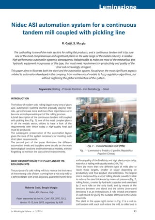
  • 1. La Metallurgia Italiana - n. 3/2014 21 Laminazione Nidec asi automation system for a continuous tandem mill coupled with pickling line R. Gatti, S. Murgia Keywords: Rolling - Process Control - Iron Metallurgy - Steel Roberta Gatti, Sergio Murgia Nidec ASI, Genova, Italy Paper presented at the Int. Conf. ROLLING 2013, Venice 10-12 June 2013, organized by AIM The cold rolling is one of the main sectors for rolling flat products, and a continuous tandem mill is by sure one of the most comprehensive and significant plants in the wide range of the metals industry. A reliable high-performance automation system is consequently indispensable to make the most of the mechanical and hydraulic equipment in a process of this type, that must meet requirements in productivity and quality of the final coil increasingly stringent. This paper aims to illustrate both the plant and the automation system, focusing on the most significant aspects related to automation developed in the company, from mathematical models to fuzzy regulation algorithms, but without neglecting the global architecture of the system.. INTRODUCTION The history of modern cold rolling began many tens of years ago; automation systems started gradually playing their role, up to increase more and more their importance so to become an indispensable part of the rolling process. A brief description of the continuous tandem mill coupled with pickling line (Fig. 1), one of the most complex plants in all the metals sector, allows to have a look of the requirements with which today a high-quality final coil must be produced. The subsequent presentation of the automation layout gives the idea of the system necessary for meeting such strict plant requirements. The second part of the paper illustrates the different automation levels and supplies some details on the main technological functions and mathematical models, without forgetting to mention the last control improvements. BRIEF DESCRIPTION OF THE PLANT AND OF ITS REQUIREMENTS The purpose of a cold rolling mill is to reduce the thickness of the entering coils of steel (coming from a hot strip mill) to a defined target with great accuracy, guaranteeing the best surface quality of the final strip and high plant productivity: note that a rolling mill usually works 24h/7d. There are more than one different type of mills able to reach these targets, smaller or larger depending on productivity and final product characteristics. The largest one is composed by a set of rolling stands (usually 5) able to reduce the steel thickness by means of pressure (Fig. 2, rolling force), created by hydraulic capsules and exercised by 2 work rolls on the strip itself; and by means of the tensions between one stand and the others (interstand tensions); 4 or, as in the picture, 6 rolls in total are present in each stand for giving the suitable stiffness to the whole assembly. The plant in the upper-right corner in Fig. 2 is a coil-to- coil tandem mill: each coil enters the mill, is rolled and is Fig. 1 – 5-stand tandem mill (PRC) Fig. 1 – Laminatoio a freddo a 5 gabbie (Repubblica Popolare Cinese)
  • 2. La Metallurgia Italiana - n. 3/201422 Memorie extracted when it has finished. Its productivity, in addition to stability of operations, can definitively increase if the coil-to-coil process is transformed into a continuous process by welding the head of a coil to the tail of the previous one (Fig. 3): in this way, the tandem can roll continuously, without stopping and restarting when a coil finishes. Because welding machines require the strip to stop for a while, an accumulator (looper) is necessary in order not to stop rolling at the tandem mill. A flying shear located at tandem exit cuts the strip when a new coil has been formed on the coiler so that the process turns back to be discontinuous. Much time can pass after hot rolling and before cold process, rust is formed on the metal and it must be eliminated from the surface of the strip before it is rolled by having the strip passed inside tanks filled with a solution of water and hydrochloric acid; this can be done in a pickling line, before the coils reach the tandem mill, or, more efficiently, the pickling line can be directly inserted between the welding machine and the 1st stand; additional loopers are required upstream of the stands to decouple the different phases giving maximum flexibility to such a plant, which can now reach 300 m length and accumulate 2000 m of strip in the loopers (see again Fig. 3; note that the figure is not to scale). A few numbers taken from a typical plant can give an idea of the complexity of the cold rolling process and, as a consequence, of its automation system (Tab. 1): this real- time control system must deal with a highly-interconnected fast process and must guarantee accuracy, reliability and productivity by means of efficient generation of references for a large number of control loops able to run at cycle times of a few ms, connected to many actuators, sensors and supervision stations. THE AUTOMATION SYSTEM Fig. 4 illustrates the theoretical scheme of the automation systems, while Fig. 5 presents the automation layout for Fig. 2 – Tandem mill applies forces and tensions to reduce the strip thickness Fig. 2 – Il laminatoio esercita forze e tiri intergabbia per ridurre lo spessore del nastro Fig. 3 – The continuous tandem mill coupled with pickling line (note that horizontal loopers are normally used) Fig. 3 – Il laminatoio continuo a freddo accoppiato con decapaggio (decatreno); si noti che normalmente vengono installati accumulatori orizzontali Entry thickness 5.5 ÷ 2 mm Exit thickness 1.5 ÷ 0.14 mm Thickness measure accuracy ± 0.01 % Total thickness reduction up to 90 % Exit speed 20 m/s Main motor power (5 stands) 15 ÷ 30 MW Rolling forces 10,000 kN Interstand tensions 100 ÷ 250 MPa Thickness performances ± 1 ÷ 3 % exit thickness in 98 % of the strip body Flatness performances ± 8 ÷ 12 I.U. Production 1.2 millions tpy the continuous mill: Level 1: includes many regulators which control• position or pressure of the hydraulic capsules, tension and thickness of the strip, speeds of the motors, and so on: inner and outer loops, concurrent loops, decoupling actions and on-line gain calibrations are often necessary; the level 1 also manages logic, sequences, hydraulics, communication with the field (sensors, actuators, electrical drives, operator desks, etc.). Data acquisition is used to investigate details in regulators. Level 2: the references to be sent to the regulators• change depending on the different products to be rolled (production programs come from the production management department – level 3) and/or due to the intrinsic tempo-variance of the plant (e.g., work rolls Tab. 1 – Some typical data summarize the high- demanding capabilities requested from a modern cold rolling mill Tab. 1 – Pochi tipici dati permettono di riassumere a colpo d’occhio i requisiti assai stringenti che un moderno laminatoio a freddo deve soddisfare loopers welder pickling stands shear
  • 3. La Metallurgia Italiana - n. 3/2014 23 Laminazione Fig. 4 – Functional structure of the automation system Fig. 4 – Struttura funzionale del sistema di automazione Fig. 5 – Automation layout for a continuous tandem mill coupled with pickling line Fig. 5 – Configurazione del sistema di automazione di un decatrenoheat up and wear) so that they are recalculated by dedicated mathematical models for each new piece (consider many tens of pieces per day); measures are collected for autoadapting the models piece-by-piece and for certifying the quality of each coil produced. The peculiar features of the continuous tandem mill automation system can be briefly described in the next paragraphs for adding more detailed information to the previous theoretical scheme. SETUP CALCULATION AND LEVEL 2 BASIC FUNCTIONS The rolling schedule to be actuated by level 1 is calculated by accurate mathematical models when the coil is welded, when it is at the pickling line or in the looper and before entering the tandem mill (final setup). Calculations dedicated to autoadapt the mathematical models for the next setup use actual plant measures and are carried out more than once while rolling the coil at the tandem mill in order to have more immediate impact on the next setup. A dedicated function (ARS – Aligned Rolling Strategy), side- by-side to autoadaption process, maintains satisfied the selected criterion (the rolling strategy) during rolling, by providing a redistribution of stand thickness reductions; e.g., ARS Load Balance guarantees the balancing of the motor powers in the stands of the tandem mill (see Fig. 6). Finally, the process servers are dedicated to collect, manage and store all of the information related to each coil (primary data, rolling schedules, adaption calculations, applied sets, quality measures) and to production and operations. They also manage the connection to the level 3 system. FLYING SETUP CHANGE The world of the mathematical models and references actuation for rolling mills is quite wide and variegated, but what surely makes the difference in a continuous tandem Fig. 6 – level 2 ARS load balance takes care that, during rolling, the stand powers are maintained in a balanced condition Fig. 6 – La funzione di livello 2 ARS load balance fa in modo di mantenere le potenze delle gabbie in una situazione adeguatamente bilanciata durante la laminazione mill is the flying setup change, that involves both modelling capabilities and real-time regulation and logic. The rolling schedule calculated for each coil to be rolled ensures the optimal references for that coil; but when the weld seam between two different coils passes through the stands, the mill operating point must move from the current state to the future state of the next product and the change has to be continuously managed by the automation system. Different intermediate sets (see Fig. 7), calculated by mathematical models and applied in the correct moments by regulators while weld seam moves along the mill, allow to maintain rolling stability (limiting the risk of strip breakage), to minimize the length of off-specification rolled strip by limiting the transition area and to maximize the production.
  • 4. La Metallurgia Italiana - n. 3/201424 Memorie THICKNESS AND TENSION CONTROL The in-tolerance thickness of the final product is what immediately appears to the final customers and has a fundamental importance both on the strip quality and on the entire plant bounty (Fig. 8). The mathematical models (level 2) calculate the nominal stand reductions and interstand tensions in order to get the desired operating conditions in the absence of disturbances. The technological controls (level 1) are designed to Fig. 7 – A weld is passing through the mill: the change of references is calculated and applied stand by stand (Continuous tandem mill – Italy) Fig. 7 – Una saldatura sta attraversando il laminatoio: il cambio dei riferimenti è calcolato ed applicato di gabbia in gabbia (Laminatoio continuo a freddo – Italia) Fig. 8 – A minimum thickness of 140 mm has been reached during a test aimed at demonstrating the feasibility of so a thin thickness in a tandem mill (Continuous tandem mill – PRC) Fig. 8 – Durante un test effettuato per dimostrare la capacità di laminare nastri estremamente sottili, si è raggiunto lo spessore di soli 140 mm (Laminatoio continuo a freddo – Repubblica Popolare Cinese) Fig. 9 – A coil with non-uniform thickness (e.g., due to skid marks at hot rolling) enters the 1st stand: AGC works very effectively so to bring the exit thickness within tolerances (Tandem Mill – Italy) Fig. 9 – Un nastro con spessore non uniforme (p. es., dovuto a skid marks durante la laminazione a caldo) imbocca la 1a gabbia: il controllo automatico di spessore (AGC) lavora con grande efficacia e mantiene in tolleranza lo spessore d’uscita (Laminatoio a freddo – Italia) Fig. 10 – Thickness and tension control system at-a- glance Fig. 10 – Un colpo d’occhio sul controllo di spessore e di tiro minimise the variations in thickness and tensions which occur during rolling (see fig. 9): for example, thickness and hardness variations in the entry strip, thermal phenomena affecting the work rolls, roll wear, roll eccentricity and friction variations cause deviations from the guaranteed target thickness in the final product if not adequately controlled by the automation system (see the scheme in Fig. 10). The Automatic Gauge Control (AGC – see Fig. 11) aims to
  • 5. La Metallurgia Italiana - n. 3/2014 25 Laminazione keep the strip exit thickness as near as possible to the target value; it is composed by three main subsystems, as hereby described. Entry AGC basically aims to keep constant and at• the correct set the thickness of the strip exiting the 1st stand so that exit AGC, by receiving an incoming material at constant thickness, works at its best for guaranteeing the target exit thickness; it acts on the hydraulic gap control (HGC) of the stand 1. The mass flow control is based on mass flow constancy principle (the material entering the stand is equal to the one going out of the stand), as shown by the following expressions (h: thickness, v: speed): (1) Then mass flow control considers as error: (2) Clearly, nullifying emassflow means obtaining strip exiting the 1st stand at the desired thickness. Mass flow control is the privileged choice because of its intrinsic and more robust characteristics: e.g., failures in laser speedometers can be successfully handled by using the encoders that are present both on entry bridle and in stand 1 (for example, the previous fig. 9 comes from a tandem mill without laser speedometers and shows that stand 1 exit thickness is maintained constant by the mass flow control in spite of entry thickness changes and rolling speed changes). The switching to the classical feedback- feedforward action is anyway possible for maintaining satisfying performances in case of heavy faults in other sensors (mainly, entry x-ray or speed encoders). The mass flow monitor aims to compensate for the mass flow estimation errors (measure errors, slipping, …). Finally, note that mass flow control reduces the effects of roll eccentricity so dramatically to become a valid alternative to the eccentricity compensation in the 1st stand. • AGC Monitor aims to bring the Exit AGC correction in range when it enters into a pre-saturation region; it recalibrates the Entry AGC thickness target, thus adjusting the material flow entering the mill according to the requirements of Exit AGC. • Exit AGC closes the loop on the speeds of the last two stands, by performing the classical feedback mechanism. The Automatic Tension Control (ATC) is aimed to maintain the interstand tensions at the preset values without affecting the AGC actions; different control configurations are used, depending on mill speed (normal run or low speed) and on product to be rolled (sheet or tin plate); fig. 12 shows the configuration in normal run mode. Two different approaches have been implemented, Fig. 11 – AGC control scheme Fig. 11 – Lo schema di controllo dell’AGC Fig. 12 – The scheme of ATC in normal run mode Fig. 12 – Lo schema dell’ATC in modalità “normal run” both of them valid and able to guarantee the required performances: Fuzzy ATC: the fuzzy principles allow the application• of a natural human language to describe the problems and their fuzzy solutions; the way of working (as well as the system maintenance) is closer to the human reasoning, where good operating experience is more important than the theory of regulation. Starting from the experience achieved in the traditional approach, the traditional control schemes have been described in words, for adapting them to the fuzzy systems, and ATC has been further improved by taking into account the experience of the skilled operators (e.g., they tend to correct both on gap and on speed when rolling forces are high). Traditional ATC: the classical controls with PID• regulators are used; the system is deeply based on the theory of regulation. Fuzzy ATC is normally used because of its benefits in tuning and maintenance. A number of rules describing how the algorithm has to consider the inputs for generating the outputs has been implemented by including both the control actions of a traditional ATC and the experience of skilled operators.
  • 6. La Metallurgia Italiana - n. 3/201426 Memorie The implemented fuzzy approach allows to well manage the intrinsic multiple-input multiple-output behaviour of ATC (MIMO control). Fig. 13, referring to the normal run configuration, allows to simply illustrate the way of working of the fuzzy ATC. The inputs to the fuzzy ATC are tension error, measured force in the downstream stand (plant feedbacks) and current speed correction coming from speed master; these crisp inputs have to be transformed (fuzzification), by some “word descriptions”, so to be properly elaborated by the inference engine (based on Mamdani’s direct method) for defining the fuzzy outputs (i.e., the control actions of ATC); the fuzzy outputs must, in turn, be re-transformed (defuzzification) into numerical values before being sent to the actuators. Tens of rules, stored in the knowledge base, allow the inference engine to generate an output; a rule is a description in the form “IF – THEN”, as in the next example: Fig. 13 – Fuzzy ATC in a tandem interstand Fig. 13 – il fuzzy ATC nell’intergabbia di un laminatoio a freddo Fig. 14 – 3D representation of strip flatness error: note that every sample is in tolerance (±12 I.U.) (Continuous tandem mill - Italy) Fig. 14 – Rappresentazione tridimensionale dell’errore di planarità del nastro: si noti che tutti i campioni sono in tolleranza (±12 I.U.) (Laminatoio continuo a freddo – Italia) IF tension error IS negative small AND force IS big THEN gap correction IS zero AND speed correction IS positive small (3) AUTOMATIC FLATNESS CONTROL The strip flatness is the most important product characteristic, along with thickness, to which the steel market is extremely sensitive. A basic requirement is that the cold rolled strip must be flat and completely free of camber; flatness defects in the final product will occur if the residual stresses remaining after rolling exceed critical values. In this case, the strip will show flatness defects as wavy edges or centre buckles. Fig. 14 shows a snapshot of the 3D representation of flatness measured during rolling. Consider that the guaranteed tolerances range around 10 I.U. (International Units) and this means to detect and control a delta length between the wavy and the tight Fig. 15 – AFC: the 3 components of shape error are corrected separately Fig. 15 – AFC: le 3 componenti dell’errore di planarità vengono corrette separatamente
  • 7. La Metallurgia Italiana - n. 3/2014 27 Laminazione fibres of 1 mm only in a wave 10 meters long. Strip flatness is measured with a shapemeter: a segmented roll located at the 5th stand exit which measures, rotor by rotor, the vertical forces to which the strip is subjected during rolling, across the width of the strip; it is then mathematically possible to obtain the longitudinal tensions from the forces and, from them, the flatness index of the strip. The flatness control processes rough measurements coming from the shapemeter in order to extract the three components of the error that the available actuators can most efficiently correct (see Fig. 15); bending and intermediate shifting quickly and accurately compensates for symmetrical defects, while tilting acts on the asymmetrical defects in the strip. Localized defects, usually a result of thermal phenomena, can be efficiently corrected by selective cooling sprays: they have a slow dynamic, but can act on a precise area of the strip. A Feedforward Force Compensation function (FFC) calculates a further contribution of bending, taking into account that the force can change during rolling, e.g. due to corrections from AGC, or from ATC. Il sistema di automazione nidec asi per un decatreno Parole chiave: Laminazione - Controllo Processi - Siderurgia - Acciaio La laminazione a freddo è uno dei settori principali della laminazione dei prodotti piani e il tandem continuo è certamente uno degli impianti più completi e significativi nell’ampio panorama della siderurgia. In un processo di tale sorta, che deve soddisfare requisiti di produttività e qualità finale del rotolo sempre più stringenti, un sistema di automazione altamente performante ed affidabile è di conseguenza indispensabile per ottenere il massimo dalle apparecchiature meccaniche ed idrauliche. Questo articolo illustra sia l’impianto che il sistema di automazione, focalizzandosi sugli aspetti più significativi dell’automazione sviluppata dalla società, dai modelli matematici agli algoritmi di regolazione fuzzy, ma senza trascurare l’architettura globale del sistema. La storia della moderna laminazione a freddo cominciò molti decenni fa; i sistemi di automazione iniziarono gradualmente a giocare il loro ruolo accrescendo sempre più la loro importanza fino a diventare una parte indispensabile del processo di laminazione. Una breve descrizione del laminatoio continuo a freddo con decapaggio in linea (decatreno), uno degli impianti più complessi dell’intero settore siderurgico, permette di dare uno sguardo ai requisiti coi quali deve essere prodotto oggi un rotolo di alta qualità. Un’idea del sistema di automazione necessario per soddisfare requisiti così stringenti in un decatreno è data dalla successiva presentazione del layout di automazione. La seconda parte dell’articolo illustra i vari livelli di automazione e fornisce alcuni dettagli relativi ai principali controlli tecnologici e modelli matematici, citando naturalmente gli ultimi miglioramenti introdotti: dai modelli matematici autoadattivi con cambio di set al volo al bilanciamento in linea dei carichi delle gabbie, dai fuzzy control applicati al controllo di tiro intergabbia ai controlli di spessore e di planarità.