1. A Water Fountain
Problem B: A Water Fountain
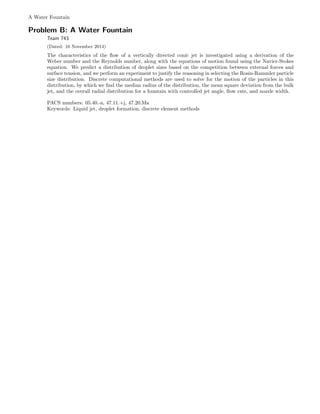
Team 743
(Dated: 16 November 2014)
The characteristics of the flow of a vertically directed conic jet is investigated using a derivation of the
Weber number and the Reynolds number, along with the equations of motion found using the Navier-Stokes
equation. We predict a distribution of droplet sizes based on the competition between external forces and
surface tension, and we perform an experiment to justify the reasoning in selecting the Rosin-Rammler particle
size distribution. Discrete computational methods are used to solve for the motion of the particles in this
distribution, by which we find the median radius of the distribution, the mean square deviation from the bulk
jet, and the overall radial distribution for a fountain with controlled jet angle, flow rate, and nozzle width.
PACS numbers: 05.40.-a, 47.11.+j, 47.20.Ma
Keywords: Liquid jet, droplet formation, discrete element methods
2. A Water Fountain 2
CONTENTS
I. Introduction 2
A. Background 2
B. Approach 3
II. Theory 3
A. Fluid Dynamics 3
1. Drag force 3
2. High Reynolds number drag force 4
3. Droplet radius 5
4. Terminal velocity 6
B. Lagrangian Formalism 7
1. Modified Euler-Lagrange with
dissipation 7
2. Single Particle Trajectory 9
3. Maximum Height 9
4. Energy loss due to dissipative forces 10
III. Computational Model 10
A. Initializing and evolving deterministic
trajectories 10
B. Statistical analysis of trajectories 11
C. Model of N particles moving with varying
initial parameters 11
IV. Experimental Methods 11
A. Drop radius experiment 12
V. Analysis of Results 12
VI. Conclusion 13
References 13
A. Navier-Stokes 13
B. C++ Numerical Integration Program 15
I. INTRODUCTION
The behaviors of liquid jets are rich with dynamical
phenomena, ranging in scale from intermolecular inter-
actions to macroscopic jet deformation and break-up.
Because of the coupling of large scale effects to micro-
scopic fluctuations, the theoretical treatment of a ver-
tically propagating water jet requires careful statistical
analysis in conjunction with the classical methods of
studying fluids. Experimentally, emergent effects such
as flow instability and atomization in jets have been the
subject of extensive research, as there is significant in-
dustrial interest in the properties of fluid jets. Such ap-
plications range from fuel jets and printing jets, in which
maximum uniform atomization is preferable, to the cre-
ation of thin fibers by cooling jets of melted material, in
which jet stability is desirable.
A. Background
Fluids have intrigued great minds in physics for sev-
eral centuries. The work of Claude Navier and Gabriel
Stokes essentially did for fluid mechanics what Newton’s
equations did for classical mechanics, in that the evo-
lution of the state of a well understood body of fluid
could be solved for using equations of motion. Perhaps
due to their dynamical complexity, fluids provide a very
broad and difficult set of problems for physicists, math-
ematicians, and engineers. Among others, a particularly
interesting case is the concept of a jet, in which one fluid
moves rapidly along a well defined, contiguous trajectory
through another fluid. Jets have intrinsic physical quirks
that arise due to the boundary of two fluids moving with
respect to each other.
The breakdown of a jet is one such trait that is at-
tributed to the propagation and amplification of surface
instabilities in the jet1
. These instabilities may result
from the internal fluctuations in the flow itself or from
impinging environmental factors. Eventually, the ampli-
tude of the surface wave exceeds the width of the jet,
causing the jet to break. In addition, these instabilities
may arise as a result of the interactions of the fluid with
the nozzle.
The study of jet breakdown has been expanded to
the case of liquid sheets2
. These breakdowns are dis-
tinct from the analogous phenomena in columnar jets
because the surface waves of a circular jet form a single
ring, whereas surface deformations in a sheet may not be
closed at all.
The case of a vertically directed conic jet forms an in-
teresting dynamical system that is well described as a
curviplanar flow under the influence of gravity and in-
terfacial forces from the surrounding fluid. When the
system is framed as a flow of discrete particles, one can
find interesting and surprising relations between observ-
able variables such as the root mean square radius, which
measures the spreading of the sheet jet, to the distribu-
tion of particle sizes created by the nozzle geometry. We
use the derivation of the Weber number and the Reynolds
3. A Water Fountain 3
number to demonstrate the connection of several useful
quantitative observables and qualitative characteristics
of the fountain flow to the design of the nozzle and the
choice of flow rate and angle.
The specific parameters that can be controlled in such
a fountain are the axial angle of the cone, φ, the volumet-
ric flow rate of the fountain, dV
dt , and the nozzle size, δr,
which has been shown to correspond directly to the size
of the droplets that the jet forms3
. Utilizing control of
only these three variables, a wide variety of fountain dis-
tributions and time of flight properties can be obtained.
B. Approach
The trajectories of the water flow can be divided into
two regimes: a deterministic one dominated by iner-
tial forces, and a stochastic regime for which the iner-
tial terms are negligible. During the breakup of a wa-
ter jet, the stream breaks up to form droplets of various
sizes and energies4
. These droplets are bound by inter-
molecular forces, and they are broken by kinetic energy
transfer from the bulk jet and from the surrounding gas.
Other phenomena that might affect droplet size include
droplet agglomeration and evaporation. By solving for
these forces, we are able to find a mean particle size about
which we can estimate a distribution of probable particle
sizes. Integrating over this domain of sizes using deter-
ministic and stochastic methods, we can find a reasonable
approximation to the radial distribution function for the
output of a conic jet.
Outside of a certain spatial domain that is very close
to the nozzle, the droplet interaction cross-section of the
droplets becomes negligible as the area swept out by the
fountain grows. This allows us to simulate the particles
using discrete element methods and the equations of mo-
tion for particles in a fluid. In this region, droplets are
treated as projectiles, and the spray of the fountain is
modelled as a diffusing monodisperse aerosol. The iner-
tial regime for particles moving through a fluid is derived
from the Navier-Stokes equations, and total particle ac-
cumulation along the radial axis is found for both massive
droplets dominated by deterministic forces as well as for
small droplets dominated by viscous terms.
This method partitioning the dynamics into two dis-
tinct modes is inspired by the symmetry breaking that
occurs in nature when the bulk properties of fluids
must compete with the particle nature of the constituent
molecules. In the conic fountain, the force of surface
tension that binds a droplet or a sheet together must
overcome drag forces and unstable configurations. As
the Weber number of the bulk fluid in this fountain sys-
tem crosses the critical boundary created by these two
competing influences, two qualitatively distinct behav-
iors emerge. Each of these situations demands a differ-
ent mathematical approach. We expand on these two
approaches in the following sections, and use a computa-
tional model to investigate the physical implications and
accuracy of our mathematics.
II. THEORY
We begin our mathematical treatment with the goal
of finding some quantitative representation of the two
qualitative regimes that we wish to simulate. We then
find the drag force on a particle in the inertial regime
by applying dimensional analysis to the Navier-Stokes
equation in terms of the Reynolds number. The Weber
number is then introduced by relating the surface tension
pressure and the Bernoulli pressure. Using our results,
we predict the mean droplet size for our flow and its
terminal velocity.
A. Fluid Dynamics
1. Drag force
In order to understand the final distribution of the
fountain flow, we must first understand the trajectories of
individual water droplets. To solve for these trajectories,
we must make reasonable assumptions about the forces
acting on the fluid, which are functions of the sizes and
velocities of the droplets. By this relation, an individual
droplet’s size directly affects its final radial displacement.
The weighted sum of the distribution of droplet sizes will
give the final radial distribution of the water jet.
We therefore consider our droplets to be particles
moving through a fluid while being acted upon by a
viscous force, F. We first assume that this force will be
a function of viscosity µ, fluid density ρ, the particle
diameter , and the velocity of the particle v, or
F = f1(v, , ρ, µ). (1)
To assist in the solution of the problem, we will utilize
the Buckingham π theorem, which will allow us to solve
for the equations of force on the particle using dimen-
sional analysis and nondimensionalization techniques.
Let the physical system depend on n parameters, which
we explicitly refer to in equation (1). We will label these
parameters as a1, . . . , an, and we will say that they
have fundamental dimensions d1, . . . , dk.
[ai] = d
αi,1
1 · · · d
αi,k
n . (2)
Our physical system from (1), f(a1, . . . , an), is
invariant under some change of dimensional scales
dj → sjdj : j ∈ [1, k]. Hence, f(a1, . . . , an) may be
recast in the form
g(π1, . . . , πn) = 0, (3)
4. A Water Fountain 4
where πi are the dimensionless combinations of {ai} and
m = n − rank(aij) ≤ n − k. Our system has 5 param-
eters, {F, ρ, v, , µ}, with 3 fundamental dimensions of
mass (M), length (L), and time (T). According to the
theorem, we will then have (5 − 3) = 2 dimensionless
combinations.
To balance the units, we first note that the viscosity
has units of mass per length per time, or
[µ] =
M
LT
. (4)
To find a functional form for the force, we may use di-
mensional analysis. As long as the units of the force
term equal those of the related parameters, we may di-
vide terms in our force function until we remove all un-
necessary dimensional dependencies. Initially, we have
units
F ρ v µ
ML
T 2
M
L3
L
T L M
LT .
If we divide both sides by ρ, cancelling units in the F
and µ terms,
F
ρ ρ v µ
ρ
L4
T 2
M
L3
L
T L L2
T .
We see that density is the only term that is dependent
on mass. Because we cannot balance the mass term us-
ing any other parameter, we conclude that the second
column will not be one of the dimensionless terms in the
Buckingham π relation. Then we have
F
ρ v µ
ρ
L4
T 2
L
T L L2
T .
We now divide by our length to the fourth power. This
yields
F
ρ 4
v µ
ρ 2
1
T 2
1
T L 1
T .
By the same reasoning used to eliminate the ρ column,
we eliminate the column,
F
ρ 4
v µ
ρ 2
1
T 2
1
T
1
T .
And finally we multiply by length squared over velocity
squared to give
F
ρv2 2
v µ
ρv
1 1
T 1.
where a length term on the right hand side is absorbed
into one of the unused parameters. For the units
to balance, the two dimensionless columns must be
functions of one another, as stated in the Buckingham π
theorem. Thus,
F
ρv2 2
= g
µ
ρv
, (5)
where g is some function of the right hand side argument.
We recognize that this argument is the reciprocal of
the Reynolds number, which is the ratio of inertial to
viscous forces. We shall denote the Reynolds number
quantity Re. Our force is then
F = ρv2 2
g (Re) . (6)
Here we have shown that the drag force acting on a par-
ticle should be proportional to the square of the velocity,
v2
, the density of the fluid, ρ, and some area, 2
, which
we will take to be proportional to the cross-sectional area
of the particle.
2. High Reynolds number drag force
Implementing the Navier-Stokes equation (see appendix
A), we have
ρ
∂v
∂t
+ v ( · v) = − P + µ 2
v (7)
at a pressure P, viscosity µ, density ρ, and velocity v.
We may substitute the Reynolds number
Re =
ρv
µ
(8)
and using
dv
dt
=
∂v
∂t
+ v ( · v) (9)
to rewrite equation (7) to give
µ
v
Re
dv
dt
= −
µ
ρv
Re P +
ρv
Re
2
v, (10)
where the coefficient of P has simply been multiplied
by (Re)(Re)−1
= 1.
For particle with a high Reynolds number, the equa-
tions of motion will be dominated by inertial terms. As
we have an ordinary differential equation, we can use
the method of dominant balance to approximate local
solutions to the motion of the high Reynolds number
particles. There must be some relation between the
terms proportional to first order terms of Re, since terms
5. A Water Fountain 5
proportional to Re−1
will be negligible:
µ
v
Re
dv
dt
∝
µ
ρv
Re P
dv
dt
∝
1
ρ
P
∂v
∂t
+ ( · v) · v ∝
1
ρ
P.
(11)
Now consider a frame where the droplet is stationary
and the fluid is moving about it. We expect inertial
terms to dominate the dynamics for a high Reynolds
number, which means that the droplet velocity will be
reasonably constant. We assume that the velocity has
no explicit time dependence, ∂v
∂t = 0. Thus,
( · v) · v ∝
1
ρ
P. (12)
To nondimensionalize the equation, we introduce di-
mensional scaling units Sρ, S , SP , and Sv for density,
length, pressure, and velocity, respectively. We define
these variables such that
xi = Si ¯xi, (13)
meaning that the variable xi may be decomposed into
nondimensionalized components, ¯xi, and a dimensional
scaling factor, Si. Using these factors to scale equation
(12), we find that
S2
v
S
=
1
Sρ
SP
S
SρS2
v = SP .
(14)
since the dimensions must be equal. Then
SρS2
v S2
= SP S2
. (15)
Since we earlier found
F ∝ ρv2 2
, (16)
we see that
F ∝ SρS2
v S2
. (17)
By using the earlier expression for SP , we finally see the
proportionality
F ∝ ∆P 2
(18)
for high Reynolds number and an order of magnitude
place holder ∆P ≡ SP .
3. Droplet radius
The water will feel competing forces due to surface ten-
sion and pressures as it travels. The Weber number is a
measure of the balance between inertial terms and sur-
face tension terms in the force equations for the droplet,
similar to the Reynolds number that relates the inertial
terms of a fluid flow to the viscous terms.
FIG. 1. The forces endured by a water droplet.
The Weber number is given by
We =
ρv2
σ
, (19)
where ρ is the density, v the velocity, and σ the surface
tension. For flows with a low Weber number, surface
tension dominates the dynamics of the jet and a contin-
uous stream can be expected. As the relative velocity of
the drops increases, either by an increase in the fountain
flow rate or by the introduction of wind, the Weber
number increases. For Weber numbers on the order of 10
to roughly 300, the forces of the surrounding fluid tend
to break the stream into discrete droplets and mist5
. To
better understand the origin of the Weber number, we
can consider two pressures acting on a the droplet. One
pressure, the Young-Laplace pressure6
, will exist due to
the surface tension. It is given by
PY L =
σ
r
. (20)
where r is the radius of the droplet. The other pressure
6. A Water Fountain 6
that a droplet will feel is the Bernoulli pressure, which is
due to the kinetic energy of the droplet. The Bernoulli
equation is given by
1
2
ρv2
+ ρgz + p0 = constant (21)
at height z under the influence of gravitational acceler-
ation g. Along the stream in a fluid, we may omit the
gravitational term since it will not vary greatly from one
particle to the next. Then we may simplify the Bernoulli
equation:
static pressure + dynamic pressure = total pressure,
(22)
where we regard the dynamic pressure as 1
2 ρv2
. Let
ρ ≡ 1
2 ρ. Then we call the Bernoulli pressure
PB = ρ v2
. (23)
The Weber number is the ratio of equations (23) and
(20),
We =
PB
PY L
. (24)
The Weber number may now be used to quantitatively
determine the traits of the droplets formed during jet
breakdown.
To determine the parameters required for droplet
formation, we want the inertial and surface tension pres-
sures to be approximately equal. At this critical point,
the Weber number is on the order of unity. Then we state
1
ρv2
σ
, (25)
which implies
σ
ρv2
. (26)
We know7
the surface tension of water at room tempera-
ture to be σ = 7.2·10−2 N
m and the density ρw = 1000 kg
m3 .
To give a preliminary indication of droplet radius at a
reasonable velocity, we will make order of magnitude
estimates. We wish to find the change in the length scale
over the course of the trajectory as the velocity changes.
We assume that the water will form a droplet nearly
immediately during flight, during a spatial interval
on the order of a centimeter. Then by rough energy
conservation in the presence of dissipative forces,
mgh
1
2
mv2
, (27)
where m is the mass of the droplet. Then
v2
2gh, (28)
which means when the droplet has dropped 1 centimeter,
its velocity squared will be on the order of
v2
2 · 10m s−2
·
1
100
m =
1
5
m2
s−2
. (29)
Substituting this estimate into our expression for critical
length scale gives
7.2 · 10−2
N m−1
1000kg m−3
· 1
5 m2
s−2
= 3.6 · 10−3
m. (30)
The estimated critical length scale will be on the order
of 3.6 mm at the time of droplet formation.
4. Terminal velocity
As the droplet falls, its velocity will be limited by air
drag and buoyancy. When these forces balance with the
gravitational acceleration, the droplet achieves terminal
velocity. Knowledge of the terminal velocity gives
important information about the radial distribution,
since the terminal velocity will be dependent on the size
of the droplets. Terminal velocity itself only becomes
relevant in the high Reynolds number regime. We
showed in section II A 1 that the force must be of the
form in equation (6). We restate this force and multiply
by π to relate the 2
term to the cross-sectional area of
our droplet. Defining our coordinates such that +ˆz is
the positive vertical direction,
FD = −
1
2
cDv2
ρairπ 2
, (31)
where cD is the drag coefficient. At Reynolds numbers
on the order of 103
, this coefficient8
is close to cD 0.5.
Then our drag force is near
FD −
π
4
ρairv2 2
. (32)
We also have the force due to gravity,
7. A Water Fountain 7
Fg = mg
=
4
3
π ( )
3
ρwg
=
4π
3
ρwg 3
,
(33)
where m is the mass of the droplet and ρ is the density
of water. Finally, we have the contribution due to
buoyancy. This term will be given by Archimedes’
principle,
FB =
4
3
π 3
ρairg. (34)
The addition of buoyant and gravitational forces give
Fg + FB =
4
3
π 3
g (ρw − ρair) , (35)
but seeing that the density of air is much less than
the density of water, we will disregard buoyancy. By
Newton’s second law, the net force of the particle can
be found by summing the external forces acting on the
particle,
m¨z = Fg + FD
=
4π
3
ρwg 3
−
π
4
ρairv2 2
,
(36)
We may substitute m = 4
3 π 3
ρw and ˙v = ¨z for a
spherical, vertically falling droplet to yield
4
3
π 3
ρw ˙v =
4π
3
ρwg 3
−
π
4
ρairv2 2
˙v = g −
3
4π 3ρw
π
4
ρairv2 2
˙v = g −
3
16
ρair
ρw
v2
.
(37)
Again, it is useful to introduce scaling factors v = Sv ¯v
and t = St¯t, where ¯v and ¯t are nondimensional. Then
we have the relation
Sv
St
˙¯v
g
= 1 −
3
16g
ρair
ρw
S2
v ¯v2
. (38)
We may define our scale factors such that the coefficients
in front of the dimensionless variables are equal to unity.
Taking the coefficient of ¯v2
,
3
16g
ρair
ρw
S2
v = 1 (39)
which means
Sv = 4
g
3
ρair
ρw
. (40)
Next, taking the coefficient of ¯˙v,
Sv
Stg
= 1 (41)
which upon substitution of Sv gives
St =
1
4g
g
3
ρw
ρair
. (42)
These scaling factors indicate the the order of magnitude
for the terminal velocity and an estimate of the time
required to reach it. We then have
Sv 4
10m s−2
· (3.6 · 10−3m)
3
·
1000kg m−3
1.2kg m−3
4
√
10 m s−1
12.6m s−1
.
(43)
for a rough estimate of the terminal velocity. The time
is takes to reach this velocity is on the order of
St
12.6m s−1
10m s−2
1.26s.
(44)
B. Lagrangian Formalism
1. Modified Euler-Lagrange with dissipation
As the radius of the jet cone increases, we assume that
the interaction of water droplets becomes negligible. The
only external forces acting on the particle are then air
drag, the gravitational force, and buoyancy. As earlier,
we will ignore the buoyancy term as it is negligible
compared to the gravitational force.
Consider a system of N droplet particles. The force
Fi may be expressed as the negative gradient of some
scalar potential,
F i
P = −
∂
∂xi
V (x1, ..., xN ). (45)
8. A Water Fountain 8
By the chain rule, we may express our gradient in terms
of generalized coordinates qα
to give
F i
P = −
N
α=1
∂V
∂qα
∂qα
∂xi
. (46)
Assume there exists an invertible Jacobian that trans-
forms our system from the xi coordinate system to the
qα
. We may then decompose the external forces on our
system and sum them, giving the partial of the potential
such that
N
i=1
F i
P ·
∂xi
∂qα
= −
∂V
∂qα
. (47)
Now we introduce stochastic conditions by considering
an external force F i
D that cannot be derived from a
deterministic potential, V (x1, x2, ..., xN ). Define a term
for the external dissipative force
Dα ≡
N
i=1
F i
D ·
∂xi
∂qα
. (48)
The total forces acting on the system are assumed to
obey superposition, since nonlinear effects are weak here
and will be absorbed into the noise terms later.
F i
= F i
P + F i
D (49)
Using (49), we rewrite (47) to be
N
i=1
F i
·
∂xi
∂qα
= −
∂V
∂qα
+ Dα. (50)
By imposing Hamilton’s principle, we find an Euler-
Lagrange equation with a Rayleigh dissipation force,9
d
dt
∂L
∂ ˙qα
−
∂L
∂qα
= Dα (51)
with Lagrangian L that describes the dynamics of the
droplets. We now require the dissipative forces, FD,
to be functions of the generalized coordinate velocities.
This is a reasonable assumption, as particle collisions
are assumed to be the mechanism for the dissipation of
energy as an object moves through a fluid. Following
the convention of Jos´e and Saletan in their Classical
Dynamics text9
, assume the ith force will be composed
explicitly of the velocity and implicitly in another
function gi(vi):
FD = −gi(vi)vi. (52)
This assumption is useful, since different order regimes
of the Reynolds number will depend on different powers
of the velocity. Substituting (52) into the dissipative
forces gives us
Dα = −
N
i=1
gi(vi)vi ·
∂vi
∂ ˙qα
. (53)
To solve for the dot product term on the right hand side,
we note that for some variable β,
∂
∂β
(vi · vi) = 2vi ·
∂vi
∂β
(54)
and
∂
∂β
(vi · vi) =
∂
∂β
v2
i = 2vi
∂vi
∂β
. (55)
Thus, we can show that
vi ·
∂vi
∂β
= vi
∂vi
∂β
. (56)
With (56) we may write our dissipative term in the form
Dα = −
N
i=1
gi(vi)vi
∂vi
∂ ˙qα
. (57)
Now we define the Rayleigh dissipative function F, such
that
Dα ≡ −
∂F
∂ ˙qα
. (58)
Then we may state this function explicitly, using an
integration variable z for the velocity:
F =
N
i=1
vi
0
gi(z)zdz. (59)
The modified Euler-Lagrange equation (51) now reads
0 =
d
dt
∂L
∂ ˙qα
−
∂L
∂qα
+
∂F
∂ ˙qα
=
d
dt
∂L
∂ ˙qα
−
∂L
∂qα
+
∂
∂ ˙qα
N
i=1
vi
0
gi(z)zdz.
(60)
9. A Water Fountain 9
For high Reynolds number, we found the drag force to be
F
1
2
cDρairπ 2
v2
. (61)
The drag coefficient8
cD is approximately cD
1
2 , the
density of air10
is about 1.2 kg m−3
, and the critical
length 3.6 · 10−3
m, as found in section II A 3. Now,
our force is
F
1.2π
4
3.6 · 10−3 2
v2
(1.22 · 10−3
v2
)N.
(62)
Using the general form derived above and defining
α0 ≡ 1.22 · 10−3
, we define our g function to be
g(vi) ≡ α0vi, (63)
keeping in mind that only one velocity term is absorbed
into the g function. The modified Euler-Lagrange
equation is now
0 =
d
dt
∂L
∂ ˙qα
−
∂L
∂qα
+
∂
∂ ˙qα
N
i=1
vi
0
gi(vi)vidvi
d
dt
∂L
∂ ˙qα
−
∂L
∂qα
+ α0
∂
∂ ˙qα
v
0
v 2
dv
d
dt
∂L
∂ ˙qα
−
∂L
∂qα
+ α0
∂
∂ ˙qα
v3
3
d
dt
∂L
∂ ˙qα
−
∂L
∂qα
+ α0 v2 ∂v
∂ ˙qα
.
(64)
The Lagrangian for this system will be of the form
L =
1
2
m · ( ˙qα
)
2
− V (qα
). (65)
2. Single Particle Trajectory
We now consider droplets in the high Reynolds number
regime that have left the spatial domain where droplet
interactions are more frequent. Additionally, we assume
that the total height of the jet is not great enough for
there to be any significant difference in the gravitational
potential difference between the top and the bottom of
the jet. Under these assumptions, we can project the
system into a azimuthally symmetric distribution. Let x
be the horizontal radial component and let z be the ver-
tical component. The Lagrangian for this configuration is
L =
1
2
m ˙x2
+ ˙z2
− mgz. (66)
We will have two modified Euler-Lagrange equations
for each coordinate. Let α ≡ α0
m . The Euler-Lagrange
equations are
¨x = −α ˙x2
+ ˙z2 ∂
∂ ˙x
˙x2
+ ˙z2
1/2
(67)
and
¨z = −g − α ˙x2
+ ˙z2 ∂
∂ ˙z
˙x2
+ ˙z2
1/2
. (68)
These equations result in
¨x = −2α ˙x ˙x2
+ ˙z2
1/2
(69)
and
¨z = −g − 2α ˙z ˙x2
+ ˙z2
1/2
. (70)
Combining these equations gives the result
¨z −
˙z
˙x
¨x = −g. (71)
3. Maximum Height
With the differential equation found above, we can
estimate the maximum height of a water droplet from
the fountain. First we shall introduce scaling factors Sx,
Sz, and St which give
Sz
S2
t
¨¯x −
Sz
Sx
Sx
S2
t
˙¯z
˙¯x
¨¯x = −g
Sz
S2
t
¨¯x −
˙¯z
˙¯x
¨¯x = −g.
(72)
For this equation to hold true, the scale on the left must
be balanced by the gravitational acceleration by the
method of dominant balance. Thus
Sz
S2
t
g, (73)
10. A Water Fountain 10
and therefore
Sz gS2
t
9.8S2
t .
(74)
The height we expect a particle to reach is approximately
one order of magnitude larger than the square of the time
spent on the trajectory.
4. Energy loss due to dissipative forces
With the modified Euler-Lagrange equations, we can
find the change in energy of the system. The Hamil-
tonian is the Legendre transform of the Lagrangian,
and it represents the total energy of the system when
conserved. Any change in the Hamiltonian over time
must be due to some gain or loss in the energy of the
droplets. Using Einstein’s index notation to sum over re-
peated indices, we write the change in energy over time as
dE
dt
=
d
dt
˙qα ∂L
∂ ˙qα
− L
= ¨qα ∂L
∂ ˙qα
+ ˙qα d
dt
∂L
∂ ˙qα
−
dL
dt
= ˙qα d
dt
∂L
∂ ˙qα
−
∂L
∂qα
= − ˙qα ∂F
∂ ˙qα
= − ˙qα ∂
∂ ˙qα
N
i=1
vi
0
gi(z)zdz.
(75)
Then the energy dissipation for our system is
dE
dt
= −
α0
3
∂v3
∂ ˙qα
= −
α0
3
∂
∂ ˙x
+
∂
∂ ˙z
˙x2
+ ˙z2
3/2
= −α0 ( ˙x + ˙z) ˙x2
+ ˙z2
1/2
.
(76)
III. COMPUTATIONAL MODEL
Using the force equations derived from section II, we
construct a computational model, written in C++, that
solves for the motion of discrete particles. To confirm the
agreement of our model with the rough predictions made
in section II A 4, we simulated a droplet falling from rest
and determined the terminal velocity. The radius of the
water droplet was set to rw = 2 · 10−3
m, whereas our
length scale in section II A 3 was ≈ 3.6 · 10−3
m. The
computational simulation yielded a value of 13.1m s−1
,
in close agreement with the theoretically predicted value
of 12.6m s−1
found in II A 4.
In the model, we introduce stochasticity to the deter-
ministic trajectories by adding noise terms to the angle of
ejection, the particle size, and the velocity. The motiva-
tion for this “front-loaded stochasticity” method comes
from the geometry of the jet. As the radius of the cone
increases, the cross-section particle density, shown in Fig-
ure 5, goes like r−2
. This is because mass is conserved as
the ring expands, and the cross-sectional area increases
like r2
. In addition, particles deviate slightly from the
original trajectory determined by φ0, the initial angle of
the cone.
FIG. 2. A representation of the distribution along a comoving
reference frame with respect to the conic sheet.
We ran large numbers of trajectories using the C++ pro-
gram, systematically varying those parameters which we
took to be related to the design of the fountain and ob-
serving the way in which the particle trajectories behaved
when constrained by the physics. Specifically, we varied
the mean droplet radius, which depends on the nozzle
geometry3
, the initial velocity magnitude, which depends
on the flow rate, and the initial velocity angle with re-
spect to the vertical axis, which depends on the angle of
the nozzle aperture.
A. Initializing and evolving deterministic trajectories
Our model simulates the trajectory of individual par-
ticles moving under the influence of drag, buoyancy, and
gravity, with adjustable parameters for the initial size,
initial velocity, and initial angle. Once again, buoyancy
was neglected. The randomness in the initial states of
the droplets was embedded into the dynamics by using
a Guassian distribution for the angle and initial velocity
of the droplets.
11. A Water Fountain 11
We used and compared two seperate distributions
for the radius of the particles. The first was a sim-
ple Gaussian and the second was the Rosin-Rammler
distribution11
. The latter distribution is an application
of the Weibull distribution, and it accounts for the fact
that droplets whose radii are smaller than the optimal
value found by the Weber number are more probable
than those whose radii are larger by the same degree.
The peak of the drop radius distribution was centered
using this optimal value, as calculated in section II A 3.
The peak of the initial velocity and angle distribution can
be chosen arbitrarily, as these are parameters controlled
by the observer.
The standard deviation in the radius Gaussian was
chosen in order to compare our models with those of other
groups in the literature.1112
The distribution of particle
sizes and velocities result from a number of competing
factors and dynamical effects.
Since the equations of motion are fairly simple, we use
a moderate timestep of ∆t = 0.05s for integration in or-
der to run larger numbers of trajectories. We employed
the forward Euler method of integration, which is tradi-
tionally a very fast, albeit dirty method. This method
can be justified since the error for forward Euler is pro-
portional to ∆t2
, and total error accumulation will be
insignificant since we are not integrating for long-time
trajectories. At every timestep, the future position of the
droplet was calculated by updating the velocity using the
equations of force, then using this velocity to extrapolate
the trajectory to the next time step. Since drag is the
only force that varies with particle velocity, this was the
only force term updated at every step.
B. Statistical analysis of trajectories
Each design-related parameter was systematically con-
trolled throughout a series of simulations. The number
of particles simulated was made large enough to create
a realistic distribution for each run. During the simula-
tion, the radial positions and times of impact correspond
to the position and time data of particles as their height
drops below zero. The radial probability was found by
creating “bins” which keep a count of the number of par-
ticles that fall in a certain interval, or bin size, δr. This
bin size can be specified to get varying levels of reso-
lution. We choose to have a resolution on the order of
centimeters, since the width of the jet is assumed to be
on the order of this length.
In order to show the difference between the two par-
ticle size distributions chosen for the model, we ran two
simulations of 1·105
particles. The particle radius was ini-
tialized using either the Gaussian or the Rosin-Rammler
distribution. Initial velocities were distributed over a
Guassian centered at v = 20m s−1
, with a standard devi-
ation of σv = 3m s−1
. The initial angles were distributed
over a Gaussian with a peak at θ = 35◦
, and a standard
deviation of σθ = 4◦
respectivly.
For these simulations, the particle distribution func-
tion is the only independent variable. The adjustable
parameter in the Rosin-Rammler distribution was set to
unity. Both distributions were centered at r = 3.6mm,
a value chosen because of the results of both the section
II A 3 theory and the experiment in IV A. The results
of the simulations can be found in Figures 6 and 7 in
Appendix B. The median radius for a fountain with a
Gaussian distribution was found to be 13.35m, with a
3.31m root-mean-square deviation from the original tra-
jectory. The Rosin-Rammler distribution under the same
conditions gave a median radius of 12.25m with an RMS
deviation of 2.06m. We choose to use the Rosin-Rammler
distribution for the radii in the following simulations.
C. Model of N particles moving with varying initial
parameters
Our next step was to find the median radius as a func-
tion of the initial angle of the jet. We started our simu-
lation at θ = 10◦
and iterated in steps of 2◦
to θ = 70◦
.
At each angle we simulated 1 · 104
particles with the ve-
locites distributed about 20m s−1
, the radii about 3.6mm,
and the angle distribution was centered about the chosen
angle.
FIG. 3. The median radius in meters plotted against the ini-
tial angle in radians. The error bar for each point is the RMS
deviation for each landing distribution (see Appendix Fig.6).
We observe a region of maximum median radius between 33◦
and 42◦
.
IV. EXPERIMENTAL METHODS
In order support the validity of the predictions made
in section II A 3, we assembled an apparatus to create
a distribution of water droplets moving downwards in a
gravitational field. A container of water was fastened at
a known height, h, above the ground. Water released in
a jet from height h formed droplets at a variable distance
from the nozzle depending on the flow rate.
12. A Water Fountain 12
FIG. 4. Plots of the radial distributions as the initial angle of the fountain is varied. The velocity for all trajectories was
centered at 20m s−1
A. Drop radius experiment
By measuring the drop count rate, the volumetric flow
rate, and the time spent in a single trial, it is possible
to establish a mean volume for each water droplet in
a constant dripping flow. We measured the drop rate
by hand while the apparatus was allowed to leak into a
beaker.
FIG. 5. The apparatus used to form the droplets measures in
the experiment.
To balance noise in the drop count, we utilized the law
of large numbers and performed trials for one minute at
a time. With the drop count rate on the order of s−1
,
and the total counted number on the order of 100 counts
per trial, reasonable averages were achieved over several
trials.
Since it is likely that the nozzle has a great deal of
influence over the size of the droplets formed, we con-
ducted trials where the nozzle produced a stream that
broke up into droplets during flight. In order to mea-
sure the high drop rate created by this configuration, we
used the SlowPro video app in conjunction with iPhone
video capability. With the app, we took a recording of
the droplets hitting a hollow cup and slowed it to 25% of
the original frame rate. For our high rate runs, we were
able to measure up to a drop rate of 7 s−1
.
Our lower bound drop rate was 2.73 s−1
. At this drop
rate, 25ml, or 25·10−6
m−3
, of water accumulated in 60s.
The volume per drop was found to be 0.152 · 10−6
m−3
.
Approximating these drops as spheres, the volume of
the drop is equal to
V =
4
3
πr3
, (77)
and using this formula, we find the average droplet ra-
dius to be 0.0034m, which is in close agreement to the
theoretical radius of highest probability found in section
II A 3.
For the upper bound drop rate of 7s−1
, 65 · 10−6
m−3
of water accumulated in 60s. The volume per droplet
was found to be 0.155 · 10−6
m−3
, yielding a volume of
0.0033m. We see that in this experiment, doubling the
drop rate had little to no effect on the mean droplet ra-
dius, and we beleive that this strongly hints at the sig-
nificance of the optimal radius of a droplet found by bal-
ancing the Weber number.
V. ANALYSIS OF RESULTS
We used a first principles view of fluid mechanics
and Lagrangian formalism to motivate a computational
model for a conic fountain. What the computational sim-
ulations for this system show is that the radial distribu-
tion of the jet flow is complicated by the simultaneous
transport of large, inertial particles and small, indeter-
ministic ones.
13. A Water Fountain 13
One interesting quirk of this fountain stems from the
significance of the drag force, the relevance of which is
related to the mass to area ratio of the water droplets.
The subtlety of this relation is shown in the change in the
spread of the jet, shown by the RMS deviation, as the
particle size is varied. For small particles, drag forces
dominate the trajectory, but they do so in such a way
that the particles don’t travel very far. This means that
the spread of a jet of small particles is limited to the
speed of diffusion.
As the radius of the droplet is increased, drag forces
become less effective. The RMS deviation increases as
the particles travel further, since the spread of the jet is
no longer limited to the speed of diffusion. However, the
drag force is also the main mechanism for creating the
spread in the distribution, and decreasing the magnitude
of the acceleration caused by drag forces has the effect of
decreasing the spread.
The competition of these effects creates a specific par-
ticle radius value that generates the maximum possible
spread. Amazingly, computational simulations show that
this optimal radius happens to be the radius predicted
in section II A 3, which is also the most probable ra-
dius found in the droplet experiment in section IV A.
It is clear that droplet size is a critical component in the
spread of a fountain, and nature seems to prefer its water
droplets to be approximately 3 mm in radius.
In addition to this, we show that the deviation of the
jet of a fountain is also heavily dependent on the angle
at which the jet starts. For fountains with very narrow
angles, the drag force acting on the particles only serves
to reduce the total height of the fountain. When the
angle is wide, however, the drag force slows small droplets
down much moreso than the larger ones. This causes
the distance between the landing coordinate of the small
droplets to be much shorter than those of the large ones,
creating a slightly inward spread of the distribution.
The key weakness of our approach lies in our neglect of
extremely small droplets and water vapor. For the bulk of
the calculations, we assume that the trajectories of parti-
cles behave inertially, and that the intermolecular forces
manifest themselves through perturbations in these tra-
jectories. This argument breaks down for droplets that
are too small to overcome viscous forces in the fluid.
To create a correction for this oversight, the distribu-
tion of the smallest droplets would have to be predicted
probabilistically. A certain amount of mist will be gen-
erated at each point along the trajectory of the jet, and
this amount will likely be proportional to the velocity of
the jet, to the droplet density, and in small part to the
vapor pressure of the surrounding fluid. As this mist is
generated, most of it will diffuse uniformly. The height
of the jet at the point where the mist is created will de-
termine how far the mist diffuses, since the mist at the
top of the arc will be in the air for the longest period.
The rate of mist accumulation at a given δr can be cal-
culated by integrating over the contributions from each
arc length segment of the jet trajectory. The contribu-
tions of one element of the jet would be proportional to
the velocity at that point and the density, since vapor
pressure would be approximately constant throughout.
The contribution of this misting distribution function
would then be added to the final radial distribution.
VI. CONCLUSION
In conclusion, we analyzed the problem of a conic liq-
uid jet using stochastic methods derived from the equa-
tions of motion for particles moving in an incompress-
ible fluid. The symmetry of the conic jet is broken by
surface instabilities introduced by the nozzle and fluctu-
ations in the molecular interactions. Taking advantage
of the probabilistic behavior of large numbers of weakly
interacting droplets, we found that noisy fluctuations in
the trajectories of these particles can be related to the
energy of the flow that is lost to dissipative forces.
REFERENCES
1L. Rayleigh, “On the instability of jets,” in Proceedings of the
London Mathematical Society, Vol. 10 (1878).
2J. York, H. Stubbs, and M. Tek, “The mechanism of disintegra-
tion of liquid sheets,” Trans. ASME 75, 1279–1286 (1953).
3e. a. Z Wang, “Experimental and theoretical investigation of
a hollow conic liquid jet atomization,” in 31st AIAA/AS-
ME/SAE/ASEE Joint Propulsion Conference and Exhibit
(1995).
4S. P. Lin and R. D. Reitz, “Drop and spray formation from a
liquid jet,” Annual Review of Fluid Mechanics 30, 85–105 (1998),
http://dx.doi.org/10.1146/annurev.fluid.30.1.85.
5A. Frohn, Dynamics of droplets (Springer, Berlin New York,
2000).
6P. S. marquis de Laplace, Trait de Mcanique Cleste, Vol. 4 (1805).
7N. Lange, Lange’s Handbook of chemistry (McGraw-Hill, New
York, 1973).
8B. McCormick, Aerodynamics, aeronautics, and flight mechanics
(Wiley, New York, 1979).
9J. Jose and E. Saletan, Classical Dynamics: A Contemporary
Approach (Cambridge University Press, 1998) pp. 129–130.
10Manual of the ICAO standard atmosphere extended to 80 kilo-
metres (262 500 feet) = Manuel de l’atmosphere type OACI :
elargie jusqu’a 80 kilometres (262 500 pieds) = Manual de la
atmosfera tipo de la OACI : ampliada hasta 80 kilometros (262
500 pies (ICAO, Montreal, 2002).
11P. of Droplet Size and V. D. in Droplet Formation Region of
Liquid Spray, Entropy , 1490–1495 (2010).
12B. Tsinghua University, “Numerical simulation study on the ef-
fects of fountain on around thermal environment,” International
Building Performance Simulation Association , 3–4 (2007).
13M. C. Y. E. F. Goedde, “Experiments on liquid jet instability,”
Journal of Fluid Mechanics 40 (1970).
14J. Plateau, Statique exprimentale et thorique des liquides soumis
aux seules forces molculaires (Gauthier-Villars, 1873).
Appendix A: Navier-Stokes
Here we derive Navier-Stokes as used in this paper
following the conventions and methods of Jos´e and
14. A Water Fountain 14
Saletan9
. Consider a region Ω(t) of a fluid. We
will concern ourselves with the result of applying
Newton’s second law to a fixed mass MΩ within this
moving volume Ω(t). Newton’s second law may be stated
FΩ = ˙PΩ, (A1)
where FΩ is the total force on this region Ω(t), and
PΩ is the total momentum in Ω(t). Assume there are
no external forces on the body, and name a parameter
p(x, t) the pressure in some region at some time. Then
force is then
FΩ = −
∂Ω
pdΣ, (A2)
where dΣ is the outward normal surface element along
this volume. By the divergence theorem, we may write
this closed loop integral as
FΩ = −
Ω
pd3
x. (A3)
The momentum PΩ on the other hand may be written
as the integral of the momentum density in this region
ρv stated as
PΩ =
Ω
ρvd3
x. (A4)
The time derivative of this integral is equal to the force.
For some scalar function W(x, t), this derivative would
be
d
dt Ω
W(x, t)d3
x =
Ω
∂W
∂t
+ · (Wv) d3
x. (A5)
Write this W function to be
W ≡ ρf(x, t). (A6)
Then we have the relation
d
dt Ω
ρfd3
x
=
Ω
ρ
∂f
∂t
+ f
∂ρ
∂t
+ · (ρv) + ρv · f d3
x.
(A7)
By the conservation of mass we know
∂ρ
∂t
= − · (ρv) , (A8)
so we’re left with
d
dt Ω
ρfd3
x
=
Ω
ρ
∂f
∂t
+ ρv · f d3
x.
(A9)
We may regard the right hand side in terms of the
substantial derivative
Dt =
∂
∂t
+ v · , (A10)
which means
d
dt Ω
ρfd3
x =
Ω
ρDtfd3
x, (A11)
and equation known as the transport theorem. With
this theorem under the constraint of Newton’s second
law we may reach Euler’s equation for an ideal fluid:
FΩ = −
Ω
pd3
x =
Ω
ρvd3
x = PΩ
−
3
i=1
∂p
∂i
=
3
i=1
ρ
∂vi
∂t
+ v · vi
− p = ρ
∂v
∂t
+ (v · ) v .
(A12)
In light of the substantial derivative,
− ρ = ρDtv. (A13)
With the continuity equation we may express this
equality in terms of the momentum-stress tensor of the
fluid
∂
∂t
(ρvi) +
∂
∂k
Πik = 0, (A14)
where
Πik = pδik + ρvivk. (A15)
We may interpret this result as a conserved current
density. Assume our fluid is incompressible. Then the
density ρ does not depend on the pressure p. Also we
15. A Water Fountain 15
have
∂ρ
∂t
= 0 (A16)
and
ρ = 0. (A17)
With these constraints we get
· v = 0. (A18)
Introduce the viscosity stress tensor such that
Πik = pδik + ρvivk − σik ≡ σik + ρvivk. (A19)
Taylor expansion to first order gives this viscosity stress
tensor as
σik = µ
∂vi
∂k
+
∂vk
∂i
−
2
3
δik
∂vj
∂j
+ ξδik
∂vj
∂j
, (A20)
where µ is the viscosity. Then our conserved current
density equation reads
ρ
∂vi
∂t
= −
∂
∂k
pδik + ρvivk − νρ
∂vi
∂k
+
∂vk
∂i
= −
∂p
∂i
− ρvk
∂vi
∂k
+ νρ
∂2
vi
∂k2
.
(A21)
Sum over i and repeated indices to give the Navier-
Stokes equation
ρ
∂v
∂r
+ (v · ) v = − p + µ 2
v. (A22)
Appendix B: C++ Numerical Integration Program
The software used to simulate these particles is called
ROOT and helped us make these pretty graphs.
FIG. 6. The distribution of the landing distance of 100,000
particles where the radii randomized under the Rosin-
Rammler distribution with the parameters stated in sec-
tionIII B. Assuming azimuthal independence the radius of
median circle is just the median of this plot which was 12.25m
with an RMS of 2.06. The average time spent by each particle
spent in the air is ≈ 1.5sec.
FIG. 7. The distribution of the landing distance of 100,000
particles where the radii randomized under the Gaussian dis-
tribution with the parameters stated in sectionIII B. Assum-
ing azmuthal independence the radius of median circle is just
the median of this plot which was 13.25m with an RMS of
3.31 The average time spent by each particle spent in the air
is ≈ 1.6sec
#include <iostream>
#include <fstream>
#include <string >
16. A Water Fountain 16
#include <TROOT. h>
#include <TCanvas . h>
#include <TCutG. h>
#include <TMath . h>
#include <TMultiGraph . h>
#include <TGraph . h>
#include <TGraph2D . h>
#include <TF3 . h>
#include <TVector3>
// Double t time = DT * NUM STEPS;
//////PARTICLE CLASS
/*Each d r o p l e t w i l l have a p o s i t i o n vector , v e l o c i t y vector , and force vector
−an i n i t i a l angle
− a radius
*/
class P a r t i c l e {
protected :
Double t pos [ 2 ] ;
Double t vel [ 2 ] ;
Double t f o r c e [ 2 ] ;
Double t theta ;
// Double t *out [ 2 ] ;
public :
// P a r t i c l e ( ) ;
void setPos ( Double t x , Double t y ) ;
void setVel ( Double t vx , Double t vy ) ;
void setForce ( Double t fx , Double t fy ) ;
void setTheta ( Double t angle ) ;
Double t getPosx ( ) ;
Double t getPosy ( ) ;
Double t getVelx ( ) ;
Double t getVely ( ) ;
Double t getForcex ( ) ;
Double t getForcey ( ) ;
Double t getTheta ( ) ;
};
void P a r t i c l e : : setPos ( Double t x , Double t y) {
pos [ 0 ] = x ;
pos [ 1 ] = y ;
}
void P a r t i c l e : : setVel ( Double t vx , Double t vy ) {
vel [ 0 ] = vx ;
vel [ 1 ] = vy ;
}
void P a r t i c l e : : setForce ( Double t fx , Double t fy ) {
f o r c e [ 0 ] = fx ;
f o r c e [ 1 ] = fy ;
}
void P a r t i c l e : : setTheta ( Double t angle ) {
theta = angle ;
}
Double t P a r t i c l e : : getPosx () {
Double t out = pos [ 0 ] ;
return out ;
}
Double t P a r t i c l e : : getPosy () {
return pos [ 1 ] ;
}
Double t P a r t i c l e : : getVelx () {
Double t out = vel [ 0 ] ;
17. A Water Fountain 17
return out ;
}
Double t P a r t i c l e : : getVely () {
return vel [ 1 ] ;
}
Double t P a r t i c l e : : getForcex () {
Double t out = f o r c e [ 0 ] ;
return out ;
}
Double t P a r t i c l e : : getForcey () {
return f o r c e [ 1 ] ;
}
Double t P a r t i c l e : : getTheta () {
return theta ;
}
///////////////////////END OF PARTICLE CLASS
#include ” P a r t i c l e . h”
using namespace std ;
#define LIFT( r , rho ) ( (4/3) * 3.14159 * ( r * r * r ) * ( rho ) * 9 . 8 1 ) ;
#define DRAGH( r , dCoeff , velocity , rho ) ( . 5 *( rho ) *( v e l o c i t y * v e l o c i t y ) * dCoeff * 3.14159 * ( r * r ) ) ;
//#define
#define DT . 0 0 1 ;
#define NUM STEPS10;
#define MASS( r , rho ) ( (4/3) * 3.14159 * ( r * r * r ) * ( rho ) ) ;
#define V E( eg ,m) ( sqrt (2 * ( eg ) / m) ) ;
//Update s h i t
#define NEW VEL(v , F,M, t ) ( v + ( (F* t ) / M) ) ;
#define NEW POS(x , v , t , a ) (x + (v* t ) + ( . 5 * a * t * t ) ) ;
#define NUM PART 10000;
#define SNR sqrt (NUM PART) ;
#define PI 3.14159;
#define RAD . 0 0 3 6 ; // mm
#define VEL 10; // m/s
#define ANGLE ( PI* 7 / 3 6 ) ;
#define SIGMA ( PI / 6 0 ) ;
#define SIGMAR . 0 0 0 2 ; // .5mm
#define SIGMAV 3; // 7 m/s
//STEP SIZES ! ! ! ! ! !
#define DTH( PI / 9 0 ) ;
#define DR . 0 0 0 2 ; //10ˆ−4 meter increment
#define DV 2;
//AMOUNT PARAMETERS WILL BE CHANGED
#define NUM ANGLES 30;
#define NUM RAD 1;
#define NUM VEL 20;
#define FITPARAM 1;
int System () {
Double t rho air , rho water , dCoeff , radius ;
Double t F l , F g , F dx , F dy ;
Double t Energy , r 0 , vi ; // found using .002 radius
Double t x 0 , y 0 , vi ;
Double t fdrag , dt , time , dh , t s c a l e ;
Double t x , y , nvy , nvx , vel ;
Double t M w;
18. A Water Fountain 18
Double t nbins = 200 ;
rho water = 1000; // kg*mˆ−3
r h o a i r = 1 . 2 ; // kg*mˆ−3
dCoeff = . 4 7 ; // drag c o e f f
dt = . 0 5 ;
dh = 1;
t s c a l e = 15;
time = 0;
t o t a l t = 0;
// r 0 = .002; // l en g th s c a l e
//TGraph2D * p l o t = new TGraph2D ( ) ;
c0 = new TCanvas( ”c1” , ” multigraph L3” ,200 ,10 ,700 ,500);
c0−>SetFrameFillColor ( 3 0 ) ;
TGraph *g1 [NUM PART] ;
P a r t i c l e *ap [NUM PART] ;
// const I n t t param ;
////////////////////////////////////////////////////
//ALLL THE ERRORBAR PARAMETERS;
Double t MEDIAN[NUM VEL] ;
// Double t Angle [ param ] ;
Double t Velocity [NUM VEL] ;
Double t ex [NUM VEL] ;
Double t RMS[NUM VEL] ;
Double t peak = 0;
//TMultiGraph *mg = new TMultiGraph ( ) ;
//TH1D *h1= new TH1D(” h1 ” ,” Postion1 ” ,400 ,0 ,30);
//h1−>GetXaxis()−> S e t T i t l e (” Position ”);
/// p l o t s landning p o s i t i o n s
TRandom * angleGenerator = new TRandom ( ) ;
TRandom * radiusGenerator = new TRandom ( ) ;
TRandom * velocityGenerator = new TRandom ( ) ;
for ( int th = 0; th < NUM VEL; th++) {
TH1D *h1= new TH1D( ”h1” , ” Postion1 ” , nbins , 0 , 1 0 0 ) ; // r e s t a r t histogram each run
//VARYING ANGLE
Double t theta = ANGLE; //+ ( th * DTH) ;
// cout << ”Theta ”<< th << ” = ” << theta << endl ;
// v i = velocityGenerator −>Gaus(VEL,SIGMAV) ; // m/s
//Energy = .5 * (4/3) * PI * ( r 0 * r 0 * r 0 ) * rho water * ( v i * v i ) ; // Energy s c a l e
//VARYING RADIUS at 35 degrees
Double t rads = RAD; //+ ( r * DR) ;
TF1 * f1 = new TF1( ” f1 ” , ”RR(x ) ” , rads , 4 * ( rads * . 2 ) ) ;
Double t avel = VEL + ( th * DV) ;
cout << ” v e l o c i t y of : ” << avel ;
/* radius = radiusGenerator−>Gaus(RAD,SIGMAR
M w = MASS( radius , rho water ) ;
// f i n d i n g v e l c o i t y to match Energy s c a l e
// v i = V E( Energy ,M w) ;
// cout << ” Velocity at radius ” << radius << ” i s :” << v i << endl ;
F g = LIFT( radius , rho water ) ;
F l= LIFT( radius , rho air ) ; */
// cout << ”Radius ” << r << ” = ” << rads << endl ;
///////////////////////////////////////////
// D i s t r i b u t i o n of angles
for ( int i = 0; i < NUM PART; i++) {
ap [ i ] = new P a r t i c l e ( ) ;
ap [ i ]−>setTheta ( angleGenerator−>Gaus( theta , SIGMA) ) ;
vi = velocityGenerator −>Gaus( avel ,SIGMAV) ; // random v e l o c i t y m/s
19. A Water Fountain 19
ap [ i ]−>setVel (TMath : : Cos ( ap [ i ]−>getTheta ( ) ) * vi ,TMath : : Sin ( ap [ i ]−>getTheta ( ) ) * vi ) ;
// cout << ap [ i]−>getTheta () << endl ;
}
///////////////////////////////////////////
for ( int j = 0; j < NUM PART; j++){
g1 [ j ] = new TGraph ( ) ; // make new graph
x 0 = 0; y 0 = 0; // ( j * dh ) ;
// make a p a r t i c l e
ap [ j ]−>setPos ( x 0 , y 0 ) ; // Start
radius = radiusGenerator−>Gaus( rads , rads * . 2 ) ; //random radius m
i f ( radius > rads ) { // Re−f i t
// cout << ” Before ” << radius << endl ;
radius = f1−>GetRandom ( ) ;
// cout << radius << endl ;
}
M w = MASS( radius , rho water ) ;
F g = LIFT( radius , rho water ) ;
F l= LIFT( radius , r h o a i r ) ;
//ap [ j]−>setTheta (TMath : : ATan( ap [ j]−>getVely ()/ ap [ j]−>getVelx ( ) ) ) ;
// cout << ” s t a r t r = ” << radius << endl ;
////////////////////////////////////////////////////////////////////////////////////////////
/*
Droplets are seperate and non−i n t e r a c t i n g with i n i t i a l p o s i t i o n s and v e l o c i t i e s
*/
for ( int i = ( j * t s c a l e /dt ) ; i < (( j +1) * t s c a l e /dt ) ; i++)
{
i f ( ap [ j]−>getPosy () >= 0 ) {
///////////Moving up
i f ( ap [ j ]−>getVely () > 0) {
// cout << ap [ j]−>getVely () << endl ;
//g1 [ j]−>SetPoint (( I n t t ) i , ap [ j]−>getPosx () , ap [ j]−>getPosy ( ) ) ; // p l o t current p o s i t i o n
////////////////////////////
//UPDATE FORCES
vel = sqrt ( ap [ j]−>getVelx () * ap [ j ]−>getVelx () + ap [ j]−>getVely ()* ap [ j ]−>getVely ( ) ) ; // v e l o c i t y
// cout << ” Velocity of : ” << v e l << endl ;
fdrag = DRAGH( radius , dCoeff , vel , r h o a i r ) ;
F dx = fdrag * TMath : : Cos ( ap [ j ]−>getTheta ( ) ) ;
F dy = fdrag * TMath : : Sin ( ap [ j ]−>getTheta ( ) ) ;
i f ( F dx >= .00001 | | ap [ j ]−>getVelx () > 0 ) { // non−zero x−force
fx = −1 * F dx ;
} else {
fx = 0;
}
fy = −1 * ( F dy + F g ) ;
///////////////////////////
// cout << ” force =:” << fy << endl ;
// cout << ” theta =: ” << ap [ j]−>getTheta ( ) ;
// cout << ap [ j]−>getTheta () << endl ;
i f (TMath : : Abs( fy ) > .00001 | | ap [ j ]−>getVely () > 0) { // non−zero y force
ap [ j ]−>setForce ( fx , fy ) ;
// cout << time << endl ;
} else { // terminal v e l o c i t y
ap [ j ]−>setForce ( fx , 0 ) ;
fy = 0;
}
////////////////////////////
// UPDATE VELOCITY
i f ( fx == 0) {
nvx = 0;
} else {
nvx = NEW VEL( ap [ j]−>getVelx ( ) , fx ,M w, dt ) ;
}
i f (TMath : : Abs( fy ) > .0000000001) {
nvy = NEW VEL( ap [ j]−>getVely ( ) , fy ,M w, dt ) ;
}
// cout << nvx << endl ;
20. A Water Fountain 20
ap [ j ]−>setVel ( nvx , nvy ) ;
//////////////////////////
///////////////////////////////////////
// UPDATE POSITION
x = NEW POS( ap [ j]−>getPosx ( ) , ap [ j ]−>getVelx ( ) , dt , fx ) ;
y = NEW POS( ap [ j]−>getPosy ( ) , ap [ j ]−>getVely ( ) , dt , fy ) ;
ap [ j ]−>setPos (x , y ) ;
////////////////////////////////
// UPDATE ANGLE
ap [ j ]−>setTheta (TMath : : ATan((TMath : : Abs( ap [ j ]−>getVely ( ) ) ) / ap [ j]−>getVelx ( ) ) ) ;
time += dt ;
}
////////////////////////////////////////////////
///////////////////////////////////////////////
///////////Moving down
i f ( ap [ j ]−>getVely () <= 0) {
// cout << ap [ j]−>getVely () << endl ;
//g1 [ j]−>SetPoint (( I n t t ) i , ap [ j]−>getPosx () , ap [ j]−>getPosy ( ) ) ; // p l o t current p o s i t i o n
////////////////////////////
//UPDATE FORCES
vel = sqrt ( ap [ j]−>getVelx () * ap [ j ]−>getVelx () + ap [ j]−>getVely ()* ap [ j ]−>getVely ( ) ) ; // v e l o c i t y
// cout << ” Velocity of : ” << v e l << endl ;
fdrag = DRAGH( radius , dCoeff , vel , r h o a i r ) ;
F dx = fdrag * TMath : : Cos ( ap [ j ]−>getTheta ( ) ) ;
F dy = fdrag * TMath : : Sin ( ap [ j ]−>getTheta ( ) ) ;
i f ( F dx >= .00001 | | ap [ j ]−>getVelx () > 0 ) { // non−zero x−force
fx = −1 * F dx ;
} else {
fx = 0;
}
fy = F dy − F g ;
///////////////////////////
// cout << ” force =:” << fy << endl ;
// cout << ” theta =: ” << ap [ j]−>getTheta ( ) ;
// cout << ap [ j]−>getTheta () << endl ;
i f (TMath : : Abs( fy ) > .00001 | | ap [ j ]−>getVely () > 0) { // non−zero y force
ap [ j ]−>setForce ( fx , fy ) ;
// cout << time << endl ;
} else { // terminal v e l o c i t y
ap [ j ]−>setForce ( fx , 0 ) ;
fy = 0;
}
////////////////////////////
// UPDATE VELOCITY
i f ( fx == 0) {
nvx = 0;
} else {
nvx = NEW VEL( ap [ j]−>getVelx ( ) , fx ,M w, dt ) ;
}
i f (TMath : : Abs( fy ) > .0000000001) {
nvy = NEW VEL( ap [ j]−>getVely ( ) , fy ,M w, dt ) ;
}
// cout << nvx << endl ;
ap [ j ]−>setVel ( nvx , nvy ) ;
//////////////////////////
///////////////////////////////////////
// UPDATE POSITION
x = NEW POS( ap [ j]−>getPosx ( ) , ap [ j ]−>getVelx ( ) , dt , fx ) ;
y = NEW POS( ap [ j]−>getPosy ( ) , ap [ j ]−>getVely ( ) , dt , fy ) ;
ap [ j ]−>setPos (x , y ) ;
////////////////////////////////
// UPDATE ANGLE
ap [ j ]−>setTheta (TMath : : ATan((TMath : : Abs( ap [ j ]−>getVely ( ) ) ) / ap [ j]−>getVelx ( ) ) ) ;
time += dt ;
}
21. A Water Fountain 21
}
//g1 [ j]−>SetPoint (( I n t t ) j , ap [ j]−>getPosx ( ) , 0 ) ;
}
// cout << ” Position at : ” << ap [ j]−>getPosx () << endl ;
// cout << time << endl ;
h1−>F i l l ( ap [ j]−>getPosx ( ) , 1 ) ;
t o t a l t = t o t a l t + time ;
time = 0;
// p o s i t i o n s [ j ] = ap [ j]−>getPosx ( ) ;
// index [ j ] = j ;
///////////////////////////////////////////////////////////////////////////////////////////
/*mg−>Add( g1 [ j ] ) ;
//g1 [ j]−>Draw ( ) ;
g1 [ j]−>SetMarkerColor ( j ) ;
g1 [ j]−>SetMarkerStyle ( 7 ) ;
g1 [ j]−>SetLineColor ( j ) ; */
//g1 [ j]−>S e t T i t l e (”Y vs X”);
//g1 [ j]−>GetXaxis()−> S e t T i t l e (”X Position ”);
//g1 [ j]−>GetYaxis()−> S e t T i t l e (”Y Position ”);
// cout << F g << endl ;
}
t o t a l t = t o t a l t / NUM PART;
cout << ” Total time : ” << t o t a l t << endl ;
for ( int a = 0; a < nbins ; a++) {
Double t temp = h1−>GetBinContent ( a ) ;
h1−>SetBinContent (a , temp/NUM PART) ;
}
/*h1−>Draw (””);
//h1−>Fit (” gaus ”);
h1−>FitPanel ( ) ;
h1−>GetXaxis()−> S e t T i t l e (” Distance of P a r t i c l e Travel ( meters ) ” ) ;
h1−>GetYaxis()−> S e t T i t l e (” P r o b a b i l i t y ( Normalized to 1)”);
h1−>S e t T i t l e (” Landing Distance D i s t r i b u t i o n With RR”); */
MEDIAN[ th ] = Median ( h1 ) ;
// cout << ”MEADIAN IS : ” << Median( h1 ) << endl ;
// cout << ”RMS ” << h1−>GetRMS( ) ;
i f (MEDIAN[ th ] > peak ) {
peak = MEDIAN[ th ] ;
cout << ”New Peak at : ” << peak << endl ;
}
Velocity [ th ] = avel ;
ex [ th ] = 0;
RMS[ th ] = h1−>GetRMS ( ) ;
// d e l e t e h1 ;
}
//////////////////////////////////////////////////////////////
// cout << ” Total time i s : ” << time << ” ” << endl ;
/*mg−>Draw(”APL”);
mg−>S e t T i t l e (”Y vs X”);
mg−>GetYaxis()−> S e t T i t l e (”Y Position ”);
mg−>GetXaxis()−> S e t T i t l e (”X Position ”); */
/*c0 −>(2);
TH1D *h1 = new TH1D(” h1 ” ,” Postion1 ” ,100 ,60 ,80);
h1−>GetXaxis()−> S e t T i t l e (” Position ”);
for ( i n t i = 0; i < NUM PART; i++) {
h1−>F i l l ( ap [ j]−>getPosx ( ) ) ;
}*/
TGraphErrors * gr = new TGraphErrors (NUM VEL, Velocity ,MEDIAN, ex ,RMS) ;
gr−>GetXaxis()−> S e t T i t l e ( ” Droplet Velocity m/ s ” ) ;
gr−>GetYaxis()−> S e t T i t l e ( ”R median ( meters ) ” ) ;
gr−>S e t T i t l e ( ”Median Fountain Radius vs I n i t i a l Velocity ” ) ;
gr−>SetMarkerColor ( 4 ) ;
gr−>SetMarkerStyle ( 2 1 ) ;
gr−>Draw( ”ALP” ) ;
//c1 −> SaveAs (”HISTO. ps ”);
// cout << ”MEADIAN IS : ” << Median( h1 ) << endl ;
cout << ”SNR : ” << SNR << endl ;
return 0;
}
22. A Water Fountain 22
double Median ( const TH1D * h1 ) { // http :// root . cern . ch/phpBB3/ viewtopic . php? f=3&t =7802
int n = h1−>GetXaxis()−>GetNbins ( ) ;
std : : vector<double> x (n ) ;
h1−>GetXaxis()−>GetCenter ( &x [ 0 ] ) ;
const double * y = h1−>GetArray ( ) ;
// exclude underflow / overflows from bin content array y
return TMath : : Median (n , &x [ 0 ] , &y [ 1 ] ) ;
}
Double t RR( Double t x) {
return = exp(−(TMath : : Power ( x/RAD, ( Double t ) FITPARAM) ) ) ;
}