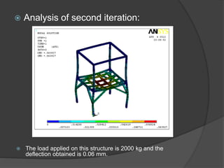
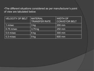
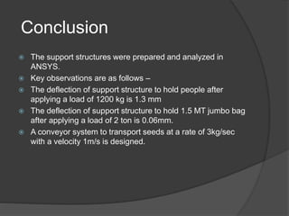
Pioneer Hi-Bred is a leading developer and supplier of advanced plant genetics. It has operations in over 90 countries and more than 10,000 employees worldwide. One of its seed processing plants in India handles over 30,000 MT of seed annually. To improve safety and efficiency, the document discusses designing support structures for personnel safety while loading trucks, an unloading structure to transfer seeds from large bags to bins, and a conveyor belt system. Load, beam, column, and conveyor belt analyses were performed to design structures that can safely handle loads and transport the required volume of seed per hour.
![Objectives
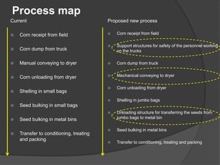
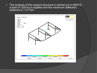
Support structures are to be designed for safety of the personnel
working on the trucks [like loaders / unloaders – hamalies]. This
requires structural designing and calculation of all the loads that
are required to design the support structures.
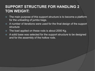
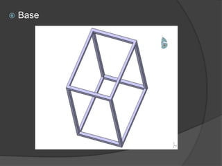
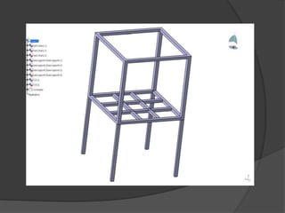
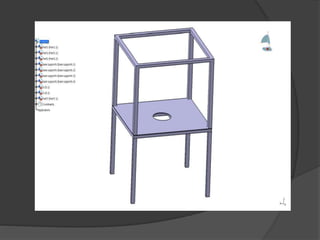
Design an unloading structure for transferring the seeds from
jumbo bags of capacity 1.5 MT to a metal bin for effective material
handling
Design a conveyor belt for the transportation of corn into the
conditioning plant.](https://image.slidesharecdn.com/08b8cb3c-64d1-4a8d-896a-246f1d907a4a-150429033841-conversion-gate02/85/DESIGN-OF-SUPPORT-STRUCTURES-4-320.jpg)