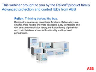
More Related Content Similar to Motor protection customer-final Similar to Motor protection customer-final (20) More from Raymund Cortez (14) 1. Relion. Thinking beyond the box.
Designed to seamlessly consolidate functions, Relion relays are
smarter, more flexible and more adaptable. Easy to integrate and
with an extensive function library, the Relion family of protection
and control delivers advanced functionality and improved
performance.
This webinar brought to you by the Relion® product family
Advanced protection and control IEDs from ABB
2. ABB is pleased to provide you with technical information regarding
protective relays. The material included is not intended to be a complete
presentation of all potential problems and solutions related to this topic.
The content is generic and may not be applicable for circumstances or
equipment at any specific facility. By participating in ABB's web-based
Protective Relay School, you agree that ABB is providing this information
to you on an informational basis only and makes no warranties,
representations or guarantees as to the efficacy or commercial utility of
the information for any specific application or purpose, and ABB is not
responsible for any action taken in reliance on the information contained
herein. ABB consultants and service representatives are available to
study specific operations and make recommendations on improving
safety, efficiency, and profitability. Contact an ABB sales representative
for further information.
ABB protective relay school webinar series
Disclaimer
May 20, 2014
l Slide 2
4. 20-May-14 | Slide 4
© ABB Group
Bob is a Regional Technical Manager with ABB’s Substation
Automation and Protection Division, providing technical support
to customers throughout the South Central United States. Bob
is a senior member of IEEE and has authored and presented
several papers on power system protection at a variety of
technical conferences throughout the United States. He is a
Registered Professional Engineer in the states of Pennsylvania
and Texas.
Bob graduated from Purdue University and joined
Westinghouse Electric Corp. After receiving a Masters degree
in Electrical Engineering from Carnegie Mellon University, Bob
was a Systems Analysis Engineer responsible for software
designed to automate system-wide coordination. He then
transferred to Kansas City where he assumed the role of
District Engineer and eventually moved to the Houston area
where he currently resides.
Presenter
Bob Wilson
5. Learning objectives
In this webinar you’ll learn:
Basic motor electrical operation
How the different types of motors can be protected
from potential hazards such as thermal damage, start-
up, faults in the windings, etc.
© ABB Group
May 20, 2014 | Slide 5
6. Introduction
There are many different types and
sizes of motors and a variety of
applications
Industry uses 50% of all electricity, of
which 65% for electric motors…nearly
one third of all electricity is used by
motors
© ABB Group
May 20, 2014 | Slide 6
7. Introduction
A rotating magnetic field, which rotates
at constant synchronous speed
(120*f)/p, can be generated by means of
a group of polyphase windings
displaced in space over an armature, if
the currents flowing through the
windings are also displaced in time
© ABB Group
May 20, 2014 | Slide 7
8. Induction motors
General observations
Stator (armature)
Single and three-phase
Windings connected to power system
Rotor
Winding not connected to power system
Wound rotor, conductors are insulated and
brought out through slip rings for connection to
starting or control devices
Squirrel-cage, conductors are connected together
on the rotor ends (not brought out)
© ABB Group
May 20, 2014 | Slide 8
9. Induction motors
General observations
Energy is transferred to rotor through magnetic
induction:
The induction motor is a double excitation
machine because it has an AC voltage applied to
its stator winding and to its winding rotor
The voltage applied to the stator winding is an
excitation voltage, usually of constant voltage and
constant frequency
The voltage applied to the rotor winding is a
variable frequency induced voltage, arising as a
result of the relative speed of the rotor with
respect to the synchronous speed
© ABB Group
May 20, 2014 | Slide 9
10. Synchronous motors
General observations
Stator (armature)
Single and three-phase
Windings connected to power system
Rotor
Windings are connected to dc source
Poles (usually salient or “sticking out”)
Poles are wound with many turns (field windings) and
dc current circulated to create alternately north and
south magnetic flux poles
Dc excitation
Brush rigging and slip rings for external excitation
Brushless – ac exciter, rectifier and control mounted on rotor
Not applied until at synchronous speed
© ABB Group
May 20, 2014 | Slide 10
12. Induction motors
Construction
The squirrel cage induction motor is the
workhorse of modern industry and is
found in virtually every phase of
manufacturing
The rotor is a cylinder mounted on a shaft.
Internally, it contains longitudinal
conductive bars (usually made of
aluminum or copper) set into grooves and
connected together at both ends by
shorting rings forming a cage-like shape.
The name is derived from the similarity
between this rings-and-bars winding and a
squirrel cage.
The bars are not always parallel to the
axial length of the rotor but can be
arranged at an angle to prevent
electromagnetic hum and to produce a
more uniform torque
© ABB Group
May 20, 2014 | Slide 12
13. Induction motors
General observations
Squirrel cage induction motor qualities:
Simple and rugged design
Low-cost
Low maintenance
Slightly lower efficiency compared to
synchronous motors
© ABB Group
May 20, 2014 | Slide 13
14. Wound rotor induction motors
General observations
A wound rotor induction motor has a stator like the squirrel cage induction motor, but a rotor
with insulated windings brought out via slip rings and brushes. However, no power is applied
to the slip rings. Their sole purpose is to allow resistance to be placed in series with the
rotor windings while starting.
Squirrel cage induction motors draw 500% to over 1000% of full load current (FLC) during
starting. While this is not a severe problem for small motors, it is for large (10's of kW)
motors. Placing resistance in series with the rotor windings not only decreases start current,
locked rotor current (LRC), but also increases the starting torque and locked rotor torque.
© ABB Group
May 20, 2014 | Slide 14
15. Wound rotor induction motors
General observations
Wound rotor induction motor qualities:
Excellent starting torque for high inertia loads
Low starting current compared to squirrel cage induction motor
Speed control. Speed is resistance variable over 50% to 100% full
speed.
Higher maintenance of brushes and slip rings compared to squirrel
cage motor
© ABB Group
May 20, 2014 | Slide 15
16. Induction motors
1.Windings
2.Slip rings
3.Brushes
4.Connections for external resistors
Wound Rotor
Squirrel Cage Rotor
© ABB Group
May 20, 2014 | Slide 16
17. Induction motors
Breakdown Torque
Full Voltage Stator Current
Pull-up Torque
Full Voltage Starting Torque
Sample Load Torque Curve
STARTING
CHARACTERISTIC
Induction motors, at
rest, appear just
like a short circuited
transformer and if
connected to the
full supply voltage,
draw a very high
current known as
the “Locked Rotor
Current.” They also
produce torque
which is known as
the “Locked Rotor
Torque”.
© ABB Group
May 20, 2014 | Slide 17
18. Induction motors
STARTING
CHARACTERISTIC
The starting current
of a motor with a
fixed voltage will
drop very slowly as
the motor
accelerates and will
only begin to fall
significantly when
the motor has
reached at least
80% of the full
speed.
Breakdown Torque
Full Voltage Stator Current
Pull-up Torque
Full Voltage Starting Torque
Sample Load Torque Curve
© ABB Group
May 20, 2014 | Slide 18
20. Motors standards
IEC
IEC is a European-based organization that publishes and
promotes worldwide, the mechanical and electrical
standards for motors, among other things. In simple terms:
the IEC is the international counterpart of the NEMA.
IEC standards are associated with motors used in many
countries. These standards can be found in the IEC 34-1-
16. Motors which meet or exceed these standards are
referred to as IEC motors.
© ABB Group
May 20, 2014 | Slide 20
21. Motors standards
The IEC torque-speed design ratings practically mirror
those of NEMA. The IEC Design N motors are similar to
NEMA Design B motors, the most common motors for
industrial applications. The IEC Design H motors are nearly
identical to NEMA Design C motors. There is no specific
IEC equivalent to the NEMA Design D motor.
The IEC Duty cycle ratings are different from NEMA
NEMA specifies :
Continuous
Intermittent
Special duty
IEC uses nine different duty cycle designations (IEC 34 -1).
© ABB Group
May 20, 2014 | Slide 21
22. Glossary
Synchronous Speed: Speed the motor’s magnetic field
rotates
Rated Speed: Speed the motor runs at when fully loaded
and supplied with rated nameplate voltage
Slip: Percent difference between a motor’s synchronous
speed and rated speed
Starting Current: The current required by the motor during
the starting process to accelerate the motor and load to
operating speed. Maximum starting current at rated voltage
is drawn at the time of energizing
Starting Time: The time required to accelerate the load to
operating speed
© ABB Group
May 20, 2014 | Slide 22
23. Glossary
Starting Torque: The rated motor torque capability during
start at rated voltage and frequency
Pull Up Torque: The minimum torque developed by the
motor during the period of acceleration from rest to the
speed at which breakdown torque occurs
Breakdown Torque: The maximum torque that a motor will
develop with rated voltage at rated frequency, where an
abrupt drop in speed will not occur
Stall Time: Permissible locked rotor time
© ABB Group
May 20, 2014 | Slide 23
24. Selection of motor protection scheme
Selection of the specific protection schemes should be based
on the following factors:
Motor horsepower rating and type
Supply characteristics, such as voltage, phases, method of
grounding, and available short-circuit current
Vibration, torque, and other mechanical limits
Nature of the process
Environment of motor, associated switching device,
Hot and cold permissible locked-rotor time and permissible
accelerating time
Time vs. current curve during starting
Frequency of starting
© ABB Group
May 20, 2014 | Slide 24
25. Motor nameplate
1. Type designation
3. Duty
5. Insulation class
7. Degree of protection [IP class]
21. Designation for locked-rotor
kVA/ HP (NEMA)
22. Ambient temperature [°C]
(NEMA)
23. Service factor (NEMA)
© ABB Group
May 20, 2014 | Slide 25
26. SERVICE FACTOR—AC MOTORS
The service factor of an AC motor is a multiplier which,
when applied to the rated horsepower, indicates a
permissible horsepower loading which may be carried
under the conditions specified for the service factor (see
14.37).
Motor nameplate
Insulation class and service factor
© ABB Group
May 20, 2014 | Slide 26
27. Potential motor hazards
Short circuits (multiphase faults)
Ground faults
Thermal damage
Overload (continuous or intermittent)
Locked rotor
Abnormal conditions
Unbalanced operation
Undervoltage and overvoltage
Reversed phases etc.
Loss of excitation (synchronous motors)
Out-of-step operation (synchronous motors)
Overheating due to repeated starts
© ABB Group
May 20, 2014 | Slide 27
28. © ABB Group
May 20, 2014 | Slide 28
Lubricant issues
Grade, contaminants, availability
Mechanical
Excessive radial loading, axial loading
Vibration
Motor protection
Bearings
© ABB Group
May 20, 2014 | Slide 28
29. © ABB Group
May 20, 2014 | Slide 29
Motor protection
Failure statistics
Motor failure rate is conservatively
estimated as 3-5% per year
In mining, pulp and paper
industry, motor failure rate
can be as high as 12%.
Motor failures divided in 3 groups:
Electrical (33%)
Mechanical (31%)
Environmental, maintenance,
& other (36%)
Motor failure cost contributors:
Repair or replacement
Removal and installation
Loss of production
© ABB Group
May 20, 2014 | Slide 29
31. Heat is developed at a constant
rate due to the current flow
Light load
Low current
Small heat development
Rated
Rated current
Nominal heat
development
Overload
High current
High heat development
Electrical
energy
Mech.
energy
Motor
Cooling air etc.
Heat
Motor thermal characteristics
© ABB Group
May 20, 2014 | Slide 31
32. Heating follows an exponential curve
Rate of temperature rise depends on motor thermal time
constant t and is proportional to square of current
−×
×≈
−
τ
θ
t
FLC
e
I
I
K 1
2
K = constant
t = time
τ = time constant
I = highest phase current
IFLC = Full Load Current
t
Θ
t
Load
Motor thermal characteristics
© ABB Group
May 20, 2014 | Slide 32
33. Cooling also follows an exponential curve
Rate of temperature drop depends on
cooling time constant (can be different
when the motor is stopped)
t
θ
t
Load
Motor thermal characteristics
© ABB Group
May 20, 2014 | Slide 33
34. Motor thermal characteristics
Heating with different loads
Heating with different time
constants
θ
Big τ
Small τ
Time
θ
Low load
High load
Time
© ABB Group
May 20, 2014 | Slide 34
35. © ABB Group
May 20, 2014 | Slide 35
Thermal overload conditions are the most
frequently occurring abnormal conditions
for industrial motors
Reduced cooling or an abnormal rise in
the motor running current results in an
increase in the motor's thermal
dissipation (conversion of electric
energy into heat) and temperature
Thermal overload protection prevents
premature degradation of the insulation
and further damage to the motor
Aθ
Bθ
% Thermal capacity
100
80
60
Thermal level
For e.g. at Startup
Thermal level
For e.g. at Standstill
Motor protection
Thermal overload protection
© ABB Group
May 20, 2014 | Slide 35
36. © ABB Group
May 20, 2014 | Slide 36
Abnormal conditions that can result in
overheating include:
Overload
Stalling or jam
Failure to start
High ambient temperature
Restricted motor ventilation
Reduced speed operation
Frequent starting or jogging
Low/imbalanced line voltage
Low frequency
Mechanical failure of the driven load,
improper installation, and unbalanced
line voltage or single phasing
Aθ
Bθ
% Thermal capacity
100
80
60
Thermal level
For e.g. at Startup
Thermal level
For e.g. at Standstill
Motor Protection
Thermal Overload Protection
© ABB Group
May 20, 2014 | Slide 36
37. A rule of thumb has been developed from tests and experience to indicate that
the life of an insulation system is approximately halved for each 10 °C
incremental increase of winding temperature, and approximately doubled for
each 10 °C decrease (the range of 7 °C–12 °C is indicated for modern
insulation systems). Thus, insulation life is related to the length of time the
insulation is maintained at a given temperature.
Thermal overload protection
© ABB Group
May 20, 2014 | Slide 37
38. Motors are ordinarily rated for use in a maximum ambient
temperatures no higher than 40 °C. Operating the motor at
a higher-than-rated ambient temperature, even though at or
below rated load, can subject the motor windings to over
temperature similar to that resulting from overloaded
operation in a normal ambient. The motor rating may have
to be appropriately reduced for operation in such high
ambient temperatures.
Motors installed at high altitudes operate in an atmosphere
of lower-than-normal air density with reduced cooling
effectiveness. This again can result in a higher-than-normal
temperature rise, and the motor rating may have to be
reduced.
Thermal overload protection
© ABB Group
May 20, 2014 | Slide 38
39. Thermal overload protection
Thermal limit curves
Hot (motor initially at ambient)
Cold (motor initially at ambient)
Motor starting (accelerating)
Time-current (normal starting)
Thermal limit
80, 90, 100 %
Apply protection characteristics that will:
Provide thermal overload protection -
49M
Not operate for motor starting - 48
49M
48
© ABB Group
May 20, 2014 | Slide 39
40. © ABB Group
May 20, 2014 | Slide 40
Start-up supervision:
Excessive starting time
Locked rotor conditions
Excessive number of start-ups (blocks the
motor from restarting)
Time between starts
Emergency start:
Overrides the cumulative start-up and thermal
overload protection functions
Enables one additional start-up of the motor
Runtime jam protection:
Protection in mechanical jam situations while
the motor is running
The function is blocked during motor start-up
Motor start-up supervision & runtime jam protection
© ABB Group
May 20, 2014 | Slide 40
41. © ABB Group
May 20, 2014 | Slide 41
When a motor is started, it draws a current well in excess of the
motor's full load rating throughout the period it takes for the motor
to run up to the rated speed. The motor starting current decreases
as the motor speed increases and the value of current remains
close to the rotor locked value for most of the acceleration period.
The startup supervision of a motor is an important function
because of the higher thermal stress developed during starting.
Motor startup supervision 66/51LRS
© ABB Group
May 20, 2014 | Slide 41
42. Failure of a motor to accelerate when its stator is energized
can be caused by:
Mechanical failure of the motor or load bearings
Low supply voltage
Open circuit in one phase of a three-phase voltage
supply.
When a motor stator winding is energized with the rotor
stationary, the motor performs like a transformer with
resistance-loaded secondary winding.
During starting, the skin effect due to slip frequency
operation causes the rotor resistance to exhibit a high
locked-rotor value, which decreases to a low running value
at rated slip speed.
Locked rotor or failure to accelerate
© ABB Group
May 20, 2014 | Slide 42
43. Using a typical locked-rotor current of six times the rated
current and a locked-rotor resistance of three times the
normal running value:
I2R ~ 62×3, or 108 times that at normal current.
I2R defines the heating effect and I2t defines the thermal capability.
Consequently, an extreme temperature must be tolerated
for a limited time to start the motor.
To provide locked-rotor or failure-to-accelerate protection,
the protective device must be set to disconnect the motor
before the stator insulation suffers thermal damage, or the
rotor conductors melt or suffer damage from repeated
stress and deformation.
Locked rotor or failure to accelerate
© ABB Group
May 20, 2014 | Slide 43
44. Locked rotor or failure to accelerate
Allowable accelerating times are
commonly specified for 100%, 90%,
and 80% starting voltages.
The acceleration time of the motor
will also change due to the starting
voltage. The approximate effect on
the motor torque capability is an
inverse relationship with the square
of the voltage; thus, at 90% voltage,
approximately 81% of rated starting
(locked rotor) torque capability will
be available from the motor. Since
the load torque characteristics are
not changed, the acceleration time
is increased.
© ABB Group
May 20, 2014 | Slide 44
45. Repeated starts can build up temperatures to dangerously
high values in stator or rotor windings, or both, unless
enough time is provided to allow the heat to dissipate.
In repeated starting and intermittent operation, the running
period is short so that very little heat is carried away by the
cooling air induced by rotor rotation
Frequent starting or intermittent operation
© ABB Group
May 20, 2014 | Slide 45
46. Induction motors and synchronous motors are usually designed for the starting
conditions indicated in NEMA MG1-1998, Articles 12.50, 20.43, and 21.43.
These standards provide for two starts in succession— coasting to rest
between starts with the motor initially at ambient temperature—and for one start
when the motor is at a temperature not exceeding its rated load operating
temperature.
It may be necessary to provide a fixed-time interval between starts, or limit the
number or starts within a period of time to ensure safe operation. A
microprocessor-based motor protection system may include this feature.
Frequent starting or intermittent operation
100%
Consumption of a
single start-up
time
Thermal Capacity
Cold Start
Cooling
Heating
X
© ABB Group
May 20, 2014 | Slide 46
47. Induction motors and synchronous motors are usually designed for the starting
conditions indicated in NEMA MG1-1998, Articles 12.50, 20.43, and 21.43.
These standards provide for two starts in succession— coasting to rest
between starts with the motor initially at ambient temperature—and for one
start when the motor is at a temperature not exceeding its rated load operating
temperature.
It may be necessary to provide a fixed-time interval between starts, or limit the
number or starts within a period of time to ensure safe operation. A
microprocessor-based motor protection system may include this feature.
Frequent starting or intermittent operation
Consumption of
a single start-up
Margin
Thermal
Capacity
Hot Start
100%
θinh
time
Cooling
Heatin
g
© ABB Group
May 20, 2014 | Slide 47
49. Frequent starting or intermittent operation
Ref: NEMA MG10
– 2013, Table 7
© ABB Group
May 20, 2014 | Slide 49
50. © ABB Group
May 20, 2014 | Slide 50
Detects sudden loss of load which is
considered as a fault condition
Trips the circuit breaker when the load
current rapidly falls below the set value
due to:
Transmission gear failures
Conveyor belt breakages
Pumps running dry
Motor protection
Loss of load supervision
© ABB Group
May 20, 2014 | Slide 50
51. © ABB Group
May 20, 2014 | Slide 51
Neg. Seq.
overcurrent
protection situations:
Phase loss/single
phasing
Unbalance load
Unsymmetrical
voltage
Motor protection
Negative sequence overcurrent protection
If the nature of the unbalance is an
open circuit in any phase, the
combination of positive and negative
sequence currents produces phase
currents of approximately 1.7 times the
previous load in each sound phase
When a three-phase induction or
synchronous motor is energized and
one supply phase is open, the motor
will not start. Under these conditions, it
overheats rapidly and is destroyed
unless corrective action is taken to de-
energize it. The heating under these
circumstances is similar to that in a
three-phase failure to start, except that
the line current is slightly lower
(approximately 0.9 times the normal
three-phase, locked-rotor current).© ABB Group
May 20, 2014 | Slide 51
52. © ABB Group
May 20, 2014 | Slide 52
Motor protection
Negative sequence overcurrent protection
A small-voltage unbalance produces a large negative-
sequence current flow in either a synchronous or induction
motor.
Z2 ~ 1/ILR pu
ILR = 6 pu, then Z2 ~ 0.167pu
Assume a V2 = 0.05 pu is applied to the motor
From V2= I2 Z2, I2 = 0.30 pu
Negative sequence current will produce negative torque
Major effect is to increase the heat delivered to the motor
Thus, a 5% voltage unbalance produces a stator negative-
sequence current of 30% of full-load current. The severity
of this condition is indicated by the fact that with this extra
current, the motor may experience a 40% to 50% increase
in temperature rise.
© ABB Group
May 20, 2014 | Slide 52
53. © ABB Group
May 20, 2014 | Slide 53
Standing
negative
sequence
(current
imbalance)
causes heating in
both the stator
and rotor
Current
Imbalance
Derates
Thermal
Capacity
Negative sequence overcurrent protection for motors
© ABB Group
May 20, 2014 | Slide 53
54. Negative sequence overcurrent protection for motors
Typical setting for the negative phase sequence voltage
protection (47) is 5%
Typical setting for the unbalance current protection (46) is
20% of nominal current
Which protection, 46 or 47, should be applied for the
unbalance protection?
Selective protection against voltage and current
unbalance is accomplished by using 46 protection
Negative-sequence voltage is most useful for
detecting upstream open phases i.e. between the
V2 measurement and the supply (selectivity not
achieved) - 47 is mostly used as backup protection
or to give alarm
© ABB Group
May 20, 2014 | Slide 54
55. RTD applications
Nickel, copper or platinum RTD are used. RTD have
well defined ohmic characteristic vs. temperature.
To measure the resistance of the RTD, lead resistance
should be compensated
Responds slowly to temperature change
Applications
Ambient temperature
Bearings
For larger motors RTD detector are placed in the motor
at the most probable hot spot
© ABB Group
May 20, 2014 | Slide 55
56. RTD applications
A simple method to determine the
heating within the motor is to
monitor the stator with RTDs.
Stator RTD trip level should be set
at or below the maximum
temperature rating of the insulation.
For example, a motor with class F
insulation that has a temperature
rating of 155°C could have the
Stator RTD Trip level be set
between 140°C to 145°C, with 145°
C being the maximum (155°C -
10°C hot spot)
The stator RTD alarm level could be
set to a level to provide a warning
that the motor temperature is rising
© ABB Group
May 20, 2014 | Slide 56
57. Multi-purpose protection, MAP
The function block can be used for any
general analog signal protection, either
under-value or over-value. The setting
range is wide, allowing various
protection schemes for the function.
The temperature protection using the
RTD sensors can be done using the
function block. The measured
temperature can be fed from the RTD
sensor to the function input that detects
too high temperatures in the motor
bearings or windings
© ABB Group
May 20, 2014 | Slide 57
58. 38 – RTD based thermal protection
Set threshold
Set trip delay
Add bias
XRGGIO130
X130-Input 1
X130-Input 2
X130-Input 3
X130-Input 4
X130-Input 5
X130-Input 6
X130-Input 7
X130-Input 8
AI_VAL1
AI_VAL2
AI_VAL3
AI_VAL4
AI_VAL5
AI_VAL6
AI_VAL7
AI_VAL8
AI_VALUE
ENA_ADD
BLOCK
TRIP
PICKUP
MAPGAPC
RTD Input
© ABB Group
May 20, 2014 | Slide 58
59. © ABB Group
May 20, 2014 | Slide 59
Used for detecting reversed
connection of the phases
causing the motor to rotate in
reverse direction
Detection by monitoring the
negative phase sequence
current during the start-up of
the motor
Operates when the negative
sequence current exceeds
the defined value
Motor protection
Phase reversal
© ABB Group
May 20, 2014 | Slide 59
60. Phase fault protection
Instantaneous
non-directional
overcurrent relay
(50) can be used
if there is a
significant
difference
between starting
current and
minimum phase-
to-phase fault
current
Otherwise
differential
protection is
required
φφ
© ABB Group
May 20, 2014 | Slide 60
61. Phase fault protection
Set relay above the asymmetrical locked rotor current
and below minimum phase-to-phase fault current
IPU > 1.6 X ILR
Symmetrical, including XS1 (source impedance)
I3f > 5 X ILR
Desirable, but not a rigid rule
© ABB Group
May 20, 2014 | Slide 61
62. Phase fault protection
Calculation of ILR and Iff
S1
φφ
S1
3φ
LRS1
LR
X
0.866
I
X
1
I
XX
1
I
=
=
+
=
XS1 is the maximum system
equivalent source impedance
XLR is the motor equivalent
reactance (stator + rotor)
VM
© ABB Group
May 20, 2014 | Slide 62
63. The short circuit element provides protection for
excessively high over current faults
Phase-to-phase and phase-to-ground faults are common
types of short circuits
When a motor starts, the starting current (which is typically
6 times the full load current) has asymmetrical components
.
These asymmetrical currents may cause one phase to see
as much as 1.7 times the RMS starting current.
To avoid nuisance tripping during starting, set the short
circuit protection pick up to a value at least 1.7 times the
maximum expected symmetrical starting current of motor.
Motor protection
Short circuit protection
© ABB Group
May 20, 2014 | Slide 63
65. If for a motor, the motor kVA rating is less than half of the
supply transformer kVA rating, over current relays may be
relied upon. In this case, there is sufficient difference
between a 3-phase short circuit at the motor terminals and
the natural motor starting current to use instantaneous
overcurrent protection.
However, in case of high voltage motors (commonly called
“big” motors), whose kVA rating is more than half of the
supply transformer kVA rating, the current for a 3-phase
fault may be less than 5 times the current for locked rotor
condition. In such cases, there is not enough difference
between the 3-phase fault current at the motor terminals
and the natural motor starting current to use instantaneous
overcurrent protection. For this case, it is recommended to
use percentage differential protection.
Motor protection
Short circuit protection
© ABB Group
May 20, 2014 | Slide 65
66. Low voltage starting
Motors are specified to successfully start with terminal
voltage as low as 70 to 85% of rated voltage
Low voltage encountered while the motor is started may
prevent it from reaching its rated speed or cause the
acceleration period to be extended resulting in the
excessive heating
© ABB Group
May 20, 2014 | Slide 66
67. Low voltage starting
VM
Normal Operating Speed
Stall Speed
Protected by
Motor start supervision
Low voltage setting
with time delay
© ABB Group
May 20, 2014 | Slide 67
68. Low voltage while running
Low voltage, while the motor is running causes an increase
in slip. The motor slows down and draws more current
from the supply
In synchronous motors the low voltage results in the higher
currents with the possibility of the motor pulling out of
synchronism
Typical Setting
75% of the nominal voltage
Time delay of 2 sec to 3 sec
© ABB Group
May 20, 2014 | Slide 68
69. Overvoltage protection
Operation of induction and synchronous motors on
moderate overvoltage is not generally considered injurious
If motor load current is constant and the motor
magnetization current increased due to overvoltage,
then motor temperatures would increase
During the starting, locked rotor current is greater due to
overvoltage. Locked-rotor protection protects motor
against thermal damage when the voltage is not more than
10% above rated voltage at the time of start
Transient overvoltages can be dangerous for motors.
Surge arresters are used to accomplish this type of
protection
Typical setting for the overvoltage protection is 10% above
nominal voltage with time delay of 2-3 seconds
© ABB Group
May 20, 2014 | Slide 69
70. Abnormal frequency
Motors are designed to operate successfully under running
conditions at rated load with a variation of 10% of rated
voltage, 5% of rated frequency
Motor speed varies directly with the applied frequency
A decrease in frequency without corresponding voltage
reduction results in an increased flux density and increased
heating losses
Protection is achieved using the frequency relay
© ABB Group
May 20, 2014 | Slide 70
71. Synchronous motor protection
Protection applied to the induction motors is applicable to
synchronous motors
Additional protection is required for field and asynchronous
operation
Reduction or loss of excitation requires reactive power
from the system. Power factor relays are recommended
Loss of the synchronism or “pull out” protection is provided
for the motors that may experience large voltage dips or
sudden increase in load that exceed the pull out torque of
the motor
A power factor relay is a good solution for out of step
operation since the power factor is very low during “pull
out” operation
© ABB Group
May 20, 2014 | Slide 71
72. Relion® Advanced Motor Protection
REM615 and REM620 common features
REM615
REM620
Both have
Draw-out & draw-in construction
with automatic CT shorting
Built-in DHCP server (web browser)
Standard communication protocols
including Modbus RTU/ASCII, DNP
and IEC61850
Optional differential protection and
arc flash protection
Customizable screen displays
including graphics
Small footprint
11 programmable alarm LEDs
73. Relion® Advanced Motor Protection
REM615 and REM620 common features
Draw-out/draw-in Construction
Speeds up installation, maintenance,
and testing of the protection
Allows the cases to be installed and
wired before the plug-in units are
delivered
Automatic CT secondary short
circuiting while plug-in unit removed
from the case…safer
Contributes to a shortened MTTR
(mean time to repair)…faster
replacement
Sealable pull-out handle to prevent
accidental (or unauthorized)
withdrawal of the plug-in unit
74. Relion® Advanced Motor Protection
REM615 and REM620 common features
11 Programmable Alarm/Target LEDs
Configurable Screen with Active
75. Relion® Advanced Motor Protection
REM615 and REM620 common features
Local or remote IED access using an internet web browser
Functions:
Viewing of alarm LEDs and event lists
Saving of event data
Parameter setting
Signal monitoring
Measurement viewing
Phasor diagram viewing
Reading of disturbance records
User access level authentication
76. Relion® Advanced Motor Protection
REM615 and REM620 common features
Embedded Native IEC61850
High speed (4 ms) relay-to-relay GOOSE communications
for faster control schemes
Does not rely on proprietary relay-to-relay communications
or hardware…standard open protocol using Ethernet
Ability to customize logic to meet special requirements
77. Relion® Advanced Motor Protection
REM615
A
B
C
D
E
F
A: Overcurrent and load loss protection for small
motors
F: Overcurrent, load loss, phase and neutral voltage,
frequency and RTD protection and power system
metering for medium to large motors
B: Differential, overcurrent, load loss and RTD
protection for medium to large motors
C: Overcurrent, load loss, phase and ground voltage
and frequency protection and power system metering
for medium motors
D: Overcurrent, load loss, phase and ground voltage,
frequency and RTD protection and power system
metering for medium motors
E: Overcurrent, load loss, phase and neutral voltage
and frequency protection and power system metering
for medium motors
Six functional
application
configurations
78. Relion® Advanced Motor Protection
REM615 without differential protection
27- Phase under voltage (2 instances)
47- Negative sequence voltage (2 instances)
59 – Phase overvoltage (2 instances)
81 - Under/over frequency (2 instances)
66/51LRS – I2T motor start supervision and frequent
start protection
50P/51P - Phase fault protection
49M - Thermal overload model
46M - Negative sequence overcurrent (2 instances)
37 - Loss of load
50G/51G – Ground fault protection
Optional (3) AFD arc flash sensors
Optional (6) RTDs
79. Relion® Advanced Motor Protection
REM615 with differential protection
66/51LRS – I2T motor start supervision
and frequent start protection
50P/51P - Phase fault protection
46M - Negative sequence overcurrent
(2 instances)
37 - Loss of load
50G/51G – Ground fault protection
87 - Differential protection
Optional (3) AFD arc flash sensors
Optional (6) RTDs
80. Relion® Advanced Motor Protection
REM620
Three functional
application
configurations
Additionally, the RER620 adds 16 programmable control
buttons and allows up to 14 RTD inputs
81. Relion® Advanced Motor Protection
REM620
66/51LRS – I2T motor start supervision and
frequent start protection
50P/51P - Phase fault protection
27 - Phase undervoltage
49M - Thermal overload model
46M – Unbalanced currents (2 instances)
37 - Loss of load
47 – Unbalanced voltages
50G/51G - Ground fault protection
81 Under/Over frequency
59 - Phase overvoltage
Optional (3) AFD arc flash sensors
Optional (14) RTDs
82. Relion® Advanced Motor Protection
REM620
66/51LRS – I2T motor start supervision and
frequent start protection
50P/51P - Phase fault protection
27 - Phase undervoltage
49M - Thermal overload model
46M – Unbalanced currents (2 instances)
37 - Loss of load
47 – Unbalanced voltages
50G/51G - Ground fault protection
81 Under/Over frequency
59 - Phase overvoltage
Optional (3) AFD arc flash sensors
Optional (14) RTDs
83. This webinar brought to you by the Relion® product family
Advanced protection and control IEDs from ABB
Relion. Thinking beyond the box.
Designed to seamlessly consolidate functions, Relion relays are
smarter, more flexible and more adaptable. Easy to integrate and
with an extensive function library, the Relion family of protection
and control delivers advanced functionality and improved
performance.
85. Thank you for your participation
Shortly, you will receive a link to an archive of this presentation.
To view a schedule of remaining webinars in this series, or for more
information on ABB’s protection and control solutions, visit:
www.abb.com/relion
May 20, 2014 | Slide 85
© ABB Group