Working Principle of Electric Generator
•
0 likes•923 views

Working Principle of Electric Generator

Recommended
More Related Content
What's hot
What's hot (20)
Similar to Working Principle of Electric Generator
Similar to Working Principle of Electric Generator (20)
More from Dr.Raja R
More from Dr.Raja R (20)
Recently uploaded
Recently uploaded (20)
Working Principle of Electric Generator
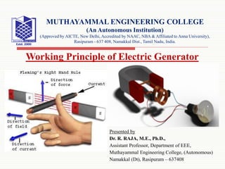
- 1. Presented by Dr. R. RAJA, M.E., Ph.D., Assistant Professor, Department of EEE, Muthayammal Engineering College, (Autonomous) Namakkal (Dt), Rasipuram – 637408 MUTHAYAMMAL ENGINEERING COLLEGE (An Autonomous Institution) (Approved by AICTE, New Delhi, Accredited by NAAC, NBA & Affiliated to Anna University), Rasipuram - 637 408, Namakkal Dist., Tamil Nadu, India. Working Principle of Electric Generator
- 2. Working Principle of Electric Generator When a conductor moves in a magnetic field, an emf is induced across the conductor. This is the only basis on which each and every rotating electric generator works (such as portable generators). According to Faraday’s law of electromagnetic induction, when a conductor links with a changing flux, it will have an induced emf across it. The value of induced emf across the conductor depends on the rate of change of flux linkage with the conductor. The direction of the induced emf in the conductor can be determined by Fleming’s Right Hand Rule. 10/23/2020 2
- 3. This rule says that on your right hand if you stretch your thumb, first finger and second finger perpendicular to each other, and if you align your right-hand thumb along the direction of motion of the conductor in the magnetic field, and first finger along the direction of magnetic field, then you second finger indicates the direction of emf in the conductor. 10/23/2020 3 Contd..
- 4. Now we will show you how does electricity get produced when we rotate single loop of a conductor in a magnetic field. During rotation, when one side of the loop comes in front of the magnetic north pole, the instantaneous motion of the conductor will be upward hence according to Fleming’s Right Hand Rule the induced emf will have inward direction. 10/23/2020 4 Contd..
- 5. 10/23/2020 5 At the same time, another side of the loop comes in front of the magnetic south pole, the instantaneous motion of the conductor will be downward hence according to Fleming’s Right Hand Rule the induced emf will have outward direction. Contd..
- 6. 10/23/2020 6 During rotation, each side of the loop comes under magnetic north pole and south pole alternately. Again in the pictures, when any of the coil sides (conductors) comes under north pole the motion of the conductor would be upward and when it comes under south pole the motion of the conductor would be downward. Contd..
- 7. Hence, the emf induced in the loop alters its direction continuously. This is the most basic conceptual model of an electric generator. We also call it a single loop electric generator. We can collect the induced emf in the loop in two different ways. Let us connect slip ring with both ends of the loop. We can connect a load with the loop through the brushes rest on the slip rings as shown. In this case, the alternating electricity produced in the loop comes the load. This is an AC electric generator. 10/23/2020 7 Contd..
- 8. We can also collect the electricity produced in the rotating loop through commutator and brush arrangement as shown in the animated picture below. In this case, the electricity produced in the loop (here the rotating loop of the single loop generator can also be referred as the armature) gets rectified through the commutator and the load gets a DC power. This is the most basic conceptual model of a DC generator. 10/23/2020 8 Contd..