High Voltage Transformers
•
0 likes•219 views

High Voltage Transformers, Voltage Regulation, Variation of Alternator Field Current, Voltage Regulation by Inserting Resistance or Inductance, Induction Regulator Method, Voltage Variation by Means of Tapped Transformer

Recommended
More Related Content
What's hot
What's hot (20)
Similar to High Voltage Transformers
Similar to High Voltage Transformers (20)
More from Dr.Raja R
More from Dr.Raja R (20)
Recently uploaded
Recently uploaded (20)
High Voltage Transformers
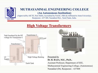
- 1. Presented by Dr. R. RAJA, M.E., Ph.D., Assistant Professor, Department of EEE, Muthayammal Engineering College, (Autonomous) Namakkal (Dt), Rasipuram – 637408 MUTHAYAMMAL ENGINEERING COLLEGE (An Autonomous Institution) (Approved by AICTE, New Delhi, Accredited by NAAC, NBA & Affiliated to Anna University), Rasipuram - 637 408, Namakkal Dist., Tamil Nadu, India. High Voltage Transformers
- 2. High Voltage Transformers High voltage transformers are normally used in high voltage labs for testing purpose. This transformer is subjected to transient voltages and surges during their normal operation when the insulation under test breaks down. To withstand these impulse voltages, the insulation of these transformers must be carefully designed. These are usually single phase, core type transformers. This type of transformer is generally oil immersed. Bakelite sheets are used for separating high tension and low tension windings. The high voltage transformers used for HV cable testing also need to supply sufficient electric current. 10/19/2020 2
- 3. This can generate a lot of heat, and as such the cooling system of these transformers is very carefully designed. Special care also needs to be taken to ensure proper transformer voltage regulation. For insulator testing purposes, the required current is very less but, while the insulator breaks down during testing, there would flow huge current through the transformer. To limit this current, a high resistance is connected in series with transformer. As insulation testing does not require as high current, high voltage transformers used for this purpose does not need to have a high kVA rating. The table below shows, the rating of transformer used for various testing purposes. Up to voltage 500 kV, typically only a single unit of high voltage transformer is used. 10/19/2020 3 Contd..
- 5. Past 500 kV, it is no longer economical to use a single transformer (the size is much too big). In these situations where more than 500 kV is required, two units are cascaded in series to produce the required voltage. The figure below shows the typical cascading connection of two transformers. 10/19/2020 5 Contd..
- 6. Low voltage is supplied to the low voltage winding of a step up transformer 1 as shown in the figure below. The tank of this transformer is earthed. The secondary of this transformer, is connected to the earthed tank and other end comes out through a high voltage bushing. The bushing is so specially designed and manufactured, that it can withstand full secondary high voltage, in respect of earthed potential of transformer tank. Another tapping terminal also runs through this high voltage bushing. The high voltage end and tapping terminal ends are connected across primary of the second transformer. 10/19/2020 6 Contd..
- 7. One end of the secondary winding of second transformer is connected to its tank. The tank of second transformer is not earthed like first transformer. This is isolated and insulated from earth for full secondary voltage of the transformer. One end of the high voltage or secondary winding of second transformer is connected to the earth and other end alone comes out from the high voltage bushing for feeding high voltage to the equipments and insulators under testing. 10/19/2020 7 Contd..
- 8. Voltage Regulation The surges on the high voltage side of the transformer should be avoided. Also for accuracy of voltage measurement, the voltage regulation of transformer should be smooth enough. Sudden variation of voltage during test also to be avoided. A voltage regulator should not distort the voltage wave form during testing. The output voltage of a high voltage transformer is regulated by changing the input voltage to the primary side. This variation of input voltage to the primary side can be done by: 1. Variation of alternator field current. 2. Inserting resistance or inductance in the supply circuit from alternator. 3. Using induction regulator. 4. Using tapped transformer. 10/19/2020 8
- 9. Variation of Alternator Field Current If one single alternator is used to supply power to the high voltage transformer, the method of variation of alternator field current can be performed. An alternator gives sinusoidal wave form of voltage at no load. But it is also desirable, that, this voltage waveform should not be distorted under load condition. This is achieved by making a larger air gap between the stator and rotor, or by using a specially designed armature winding of alternator. 10/19/2020 9
- 10. 10/19/2020 10 For regulating voltage, no impedance is required to be connected in series with the primary of the transformer, in this case. So the voltage waveform distortion due to inserted impedance can be avoided in voltage regulation via the variation of alternator field current. Contd..
- 11. The field current of the alternator is varied by a voltage divider, connected across DC supply to the field. In this method, zero voltage can be achieved by neutralizing residual magnetism of field by severing required field current. 10/19/2020 11 Contd..
- 12. Voltage Regulation by Inserting Resistance or Inductance When there is no provision of using separate alternator for high voltage testing in the lab, this method is applied. The high voltage transformer is fed from the AC supply mains when testing small equipment. The variation of supply voltage to the H. V. transformer is obtained by inserting resistance in series with the AC supply. A sliding >resistance is most suitable for achieving smooth regulation of voltage supplied to the transformer primary. Sometimes the resistance can also be connected across the main supply and used as a voltage divider, to supply a variable voltage to the transformer. 10/19/2020 12
- 13. 10/19/2020 13 This method is quite simple but it suffers from a power loss problem, as the power loss across the resistance too high for high power tests. The high resistance required for high power applications also means that this method is not cost effective. Because of these disadvantages, this method is limited low-medium power applications. Generally, this is limited to equipment rated from 2 kVA to 3 kVA. Contd..
- 14. Instead of resistance, voltage regulation can be achieved by connecting a choke coil (inductor) in series with the primary of the transformer. Voltage variation can be obtained by changing the position of the iron core in the choke coil. That means, by inserting and withdrawing iron core inside the coil, the voltage variation is achieved. Due to lower power loss, this method is more efficient than the resistance method. 10/19/2020 14 Contd..
- 15. Despite this advantage, this method still has some inherent disadvantages: 1. For higher power, very large size of this choke coil is required. 2. There is always a good chance of voltage distortion due to iron core in the coil. 3. Another disadvantage of this method, is in fact that increase of its inductance will increase the primary voltage of the transformer instead of decreasing it if the power factor of the load on the secondary side of the testing transformer is leading as is often the case. 10/19/2020 15 Contd..
- 16. Induction Regulator Method Inductance regulator control is suitable for all ranges of power. It can be efficiently used for all load and power factors. Smooth voltage regulation from zero to full range can be achieved by this method. An induction regulator is essentially a variable transformer. The secondary voltage of this variable transformer can be varied by changing primary turns. Variation of primary turns is achieved by rotating a knob attached to the transformer. In this type of variable transformer, the number of turns in the primary and secondary windings are same. But when we rotate the said knob attached to the transformer the number of active turns across primary varies, hence turns ratio changes which ultimately results to variable secondary voltage. 10/19/2020 16
- 17. During the design of this type of transformer, it is important that the transformer winding on the rotor side is adequately engineered such that it does not distort the actual wave form of the test voltage. Induction regulator method is most suitable for the high voltage transformer, used for power cable testing purpose. Because its gradual voltage variation at loads of any magnitude is advantageous for such work. 10/19/2020 17 Contd..
- 18. Voltage Variation by Means of Tapped Transformer In this method of transformer voltage regulation, a tapped transformer is used. The theory of voltage variation by a tapped transformer is quite simple. In this arrangement, the primary side of the transformer is connected with the LT supply main. The secondary winding of the transformer is tapped at various points. The voltage at primary of HT transformer is supplied from these tapped points. When the contact of tapping switch moves from one tap to another, these would be a chance of opening the secondary circuit of tapping transformer. Due to this opening, high voltage transformers have a high chance of surging. 10/19/2020 18
- 19. To avoid this situation two contact brushes are used for tap changer switch. It makes contact with adjacent studs and with a buffer resistance or reactance coil between them to prevent short circuit of a section of the transformer winding. In the diagram below, we have shown a two winding transformer as a tapped transformer. Not that an auto transformer can also be used. 10/19/2020 19 Contd..
- 20. For gradual regulation a number of course tapping are used together with fine tappings. This method of voltage regulation by tapped transformer is advantageous for its high efficiency and small wave form distortion as there is no voltage drops in the circuit, only the voltage wave is stepped up. As the winding is tapped the voltage regulation is not very smooth. But it can be made smoother by using very large number of taps in the secondary winding of tapped transformer but it increases cost of the transformer. Hence this method of voltage regulation is used on high voltage transformer only when it is required for large and expensive switchgear testing. 10/19/2020 20 Contd..