VIP Call Girls Service Hitech City Hyderabad Call +91-8250192130
Transformer.pdf
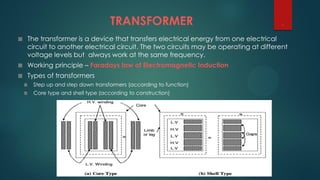
1. The transformer is a device that transfers electrical energy from one electrical
circuit to another electrical circuit. The two circuits may be operating at different
voltage levels but always work at the same frequency.
Working principle – Faradays law of Electromagnetic Induction
Types of transformers
Step up and step down transformers (according to function)
Core type and shell type (according to construction)
TRANSFORMER 1
2. Transformer is a significant component of ac power systems;
it makes possible electric generation at the most economical generator
voltage
power transfer at the most economical transmission voltage,
power utilization at the most suitable voltage for the particular utilization
device.
SIGNIFICANCE of TRANSFORMER 2
4. Applications of Transformers in Power Sector
1. It can rise or lower the level of level of Voltage or Current ( when
voltage increases, current decreases and vice versa because P =V x I,
and Power is same ) in an AC Circuit
2. It can be used to prevent DC from passing from one circuit to the
other.
3. it can isolate two circuits electrically.
4. Providing neutral conductor
5. Harmonics mitigation
4
5. Power Transformer
Power transformers are used in transmission network of higher voltages for step-up and step
down application (400 kV, 200 kV, 110 kV, 66 kV, 33kV) and are generally rated above
200MVA.
5
6. Power transformer is used for the transmission purpose at heavy load,
high voltage greater than 33 KV & 100% efficiency. It also having a big in size
as compare to distribution transformer, it used in generating station and
Transmission substation with high insulation level.
Power Transformers are used in Transmission network so they do not
directly connect to the consumers, so load fluctuations are very less. These
are loaded fully during 24 hr.'s a day, so Cu losses & Iron losses takes place
throughout day
6
7. Power Transformers
These transformers are designed to utilize the core to maximum.
Naturally these transformers have the matched iron losses and copper losses at peak load
(i.e. the maximum efficiency point where both the losses match).
Distribution Transformers
It depends on the typical load cycle for which it has to supply. Definitely Core design will
be done to take care of peak load and as well as all-day-efficiency.
Power transformer generally operated at full load. Hence, it is designed such that copper
losses are minimal.
However, a distribution transformer is always online and operated at loads less than full
load for most of time. Hence, it is designed such that core losses are minimal.
In Power Transformer the flux density is higher than the distribution transformer.
7
8. Tap-changing Transformer
• A tap changer is a connection point selection mechanism along a
power transformer winding that allows a variable number of turns to
be selected in discrete steps.
• A transformer with a variable turns ratio is produced, enabling
stepped voltage regulation of the output. The tap selection may be
made via an automatic or manual tap changer mechanism.
8
9. Booster Transformer
• Boost transformer is a type of transformer used to make adjustments to the voltage
applied to alternating current equipment.
• Boost connections are used in several places such as uninterruptible power
supply (UPS) units for computers, and in the tanning bed industry.
• Boost transformers can be used to power low voltage circuits including control, lighting
circuits, or applications that require 12, 16, 24, 32 or 48 volts, consistent with the design's
secondary's.
• The transformer is connected as an isolating transformer and the nameplate kVA
rating is the transformer’s capacity
9
10. Auto-Transformer
an auto -transformer is a transformer with only one winding and the
same windings acts as both the primary and secondary sides of a
transformer.
Auto -transformers are often used to step up or step down a
constant supply voltage.
As mentioned earlier auto -transformers consists of a single
winding.
The primary voltage is applied across the two ends of the winding.
The primary and the secondary share the same neutral point.
The secondary voltage is obtained across any one of the tapping
and the neutral point.
10