2. 72 CHAPTER 3 HARMONIC GENERATION-1
TABLE 3.1 Major Power Quality Problems
No Category Spectral Typical Typical Voltage
Content Duration Magnitude
1 Waveform Distortion
DC offset
Harmonics
Interharmonics
Notching
Noise-Common mode and
normal mode
0–5000Hz
0–6kHz
Broad band
Steady state
Steady state
Steady state
Steady state
Steady state
0–0.25%
0–30%
0–5%
2 Voltage fluctuations
Flicker
Voltage unbalance
Intermittent
Steady state
01–7%
Pst and Plt
0.5–4%
3 Transients-Impulsive
Nanosecond
Microsecond
Millisecond
5 ns rise
1 μs rise
0.1 ms rise
<50 ns
50 ns–1 ms
>1 ms
4 Transients-Oscillatory
Low frequency
Medium frequency
High frequency
<5 kHz
5–500 kHz
0.5% MHz
0.3–50 ms
20 μs
5 μs
0–4 pu
0–8 pu
0–4 pu
5 Short-duration variations
a. Instantaneous
Interruptions
Sags (dips)
Swell
b. Momentary
Interruptions
Sags
Swell
c. Temporary
Interruptions
Sags
Swell
0.5–30 cycle
0.5–30 cycle
0.5–30 cycle
30 cycles–3 s
30 cycles–3 s
30 cycles–3 s
3 s–1 min
3 s–1 min
3 s–1 min
<0.1 pu
0.1–0.9 pu
1.1–1.8 pu
<0.1 pu
0.1–0.9 pu
1.1–1.4 pu
<0.1 pu
0.1–0.9 pu
1.1–1.2 pu
6 Long Duration variations
Sustained interruption
Undervoltage
Overvoltage
•1min
•1 min
•1 min
0.0 pu
0.8-0.9 pu
1.1-1.2 pu
7 Frequency variations <10 s
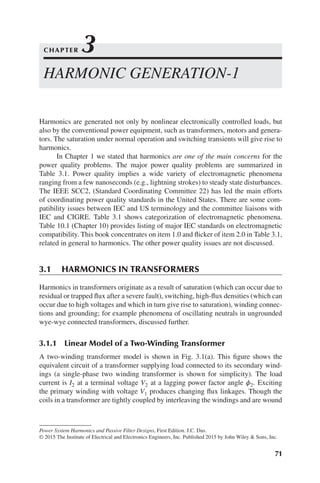
on a magnetic material of high permeability, all the flux produced by primary wind-
ings does not link with the secondary windings. The winding leakage flux gives rise
to leakage reactances. Φm is the main or mutual flux, assumed to be constant. In the
secondary winding, the ideal transformer produces an EMF E2 due to mutual flux
linkages and in the primary windings induced EMF, E1 opposes the EMF induced
in the secondary windings, E2. There has to be a primary magnetizing current even
3. 3.1 HARMONICS IN TRANSFORMERS 73
r1
V1
Im
Rm
E1
Ideal transformer
(a)
Ration = n1/n2
E2
−bm
x1 r2 x2
I0 I1 I2
V2 ZL
Ie
n2 n1
I’1
+
−
V1 VL Load
IL
(b)
Simplified
Transformer model
R X
+
−
Figure 3.1 (a) Equivalent circuit of a two winding transformer, (b) simplified equivalent
circuit.
at no load, in time- phase with its associated flux, to excite the core. The pulsation
of flux in the core produces losses. Considering that the no-load current is sinusoidal
(which is not true under magnetic saturation), it must have a core loss component due
to hysteresis and eddy currents:
I0 =
√
I2
m + I2
e (3.1)
where Im is the magnetizing current, Ie is the core loss component of the current,
and I0 is the no-load current; Im and Ie are in phase quadrature. The generated EMF
because of flux Φm is given by
E2 = 4.44fn2Φm (3.2)
where E2 is in volts when Φm is in Wb∕m2, n2 is the number of secondary turns, and
f is the frequency. As primary ampère turns must be equal to the secondary ampère
4. 74 CHAPTER 3 HARMONIC GENERATION-1
turns, that is, E1I1 = E2I2, we can write:
E1
E2
=
n1
n2
= n and
I1
I2
≈
n2
n1
=
1
n
(3.3)
The current relation holds because the no-load current is small. The terminal relations
can now be derived. On the primary side, the current is compounded to consider the
no-load component of the current, the primary voltage is equal to − E1 (to neutralize
the EMF of induction) and I′
1
r1 and I′
1
x1 are resistive and inductive (lagging power fac-
tor) drop in the primary windings. On the secondary side the terminal voltage is given
by the induced EMF E2 less I2r2 and I2x2 voltage drops in the secondary windings.
The phasor diagram corresponding to Fig. 3.1(a) is in Fig. 3.2(a). See Refs. [1–3].
By pulling the secondary parameters of the transformer to the primary side
multiplied by the square of the turns-ratio, and ignoring the magnetization and eddy
current branches a very simplified model results, as shown in Fig. 3.1(b). Its phasor
diagram is in Fig. 3.2(b). The percentage impedance specified by the manufacturer
and X/R ratio is based on this model. This model is good for linear fundamental
V1
I0
Ie
Im
Φm
I0
I2
V2
E2 = E1/n
(a)
(b)
R = r1 + n2
r2
X = X1 + n2
X2
I2r2
I2x2
−E1
Iʹ1x1
Iʹ1r1
ILX
ILR
IL
ILZ
VL
V1
Iʹ1
I1
ϕ1
ϕ
ϕ2
Figure 3.2 (a) Phasor diagram corresponding to the equivalent circuit in Fig. 3.1(a),
(b) phasor diagram corresponding to Fig. 3.1(b).
5. 3.1 HARMONICS IN TRANSFORMERS 75
frequency load flow and cannot be applied to harmonic analysis. The appropriate
transformer models are discussed in Chapter 12.
The expression for hysteresis loss is
Ph = KhfBs
m (3.4)
where Kh is a constant and s is the Steinmetz exponent, which varies from 1.5 to 2.5,
depending on the core material; generally, it is equal to 1.6.
The eddy current loss is
Pe = Kef2
B2
m (3.5)
where Ke is a constant. Eddy current loss occurs in core laminations, conductors,
tanks, and clamping plates. The core loss is the sum of the eddy current and hysteresis
loss. In Fig. 3.2(a), the primary power factor angle 𝜙1 is > 𝜙2.
3.1.2 B-H Curve and Peaky Magnetizing Current
For economy in design and manufacture, transformers are operated close to the knee
point of saturation characteristics of magnetic materials. Figure 3.3 shows a B − H
curve and the magnetizing current waveform.
Referring to Fig. 3.3, the magnetic current variation can be plotted as illus-
trated. An ascending flux density corresponding to point P on hysteresis loop and
point Q on the sinusoidal wave requires x times the magnetizing current. If a number
of such points are plotted, the resulting current curve deviates considerably from the
sinusoidal. Also see Ref. [4].
A sinusoidal flux wave, required by sinusoidal applied voltage, demands a mag-
netizing current with a harmonic content. Conversely, with a sinusoidal magnetizing
1.5
P Q
Current
Current
Flux
density
Wb/m
2
BH curve
x 0 90 270
180 360
Current
(peaky)
Angle
Flux density
(sinusoidal)
0.75
0
−0.75
−1.5
Figure 3.3 Transformer B-H curve and derivation of peaky magnetizing current.
6. 76 CHAPTER 3 HARMONIC GENERATION-1
current, the induced EMF is peaky and the flux wave is flat topped. The peaky current
wave has odd harmonics: a flat-topped flux density waveform can be written as:
B = B1 sin 𝜔t + B3 sin 3𝜔t + B5 sin 5𝜔t + … (3.6)
This gives :
e = 𝜔Ac(B1 cos 𝜔t + B3 cos 3𝜔t + B5 cos 5𝜔t + … ) Volts per turn (3.7)
where Ac is the area over which the flux density acts.
In a system of three-phase balanced voltages, the triplen harmonic voltages are
cophasial:
In phase a:
v3 sin(3𝜔t + 𝛼3) (3.8)
In phase b:
v3 sin[3(𝜔t − 120o
) + 𝛼3] = v3 sin(3𝜔t + 𝛼3) (3.9)
In phase c:
v3 sin[3(𝜔t − 240o
) + 𝛼3] = v3 sin(3𝜔t + 𝛼3) (3.10)
The third harmonics and all triplen harmonics are in time phase with each other.
3.1.3 Effect of Transformer Construction and Winding
Connections
If the impedance to the third harmonic is negligible, only a very small third har-
monic EMF is required to circulate a magnetizing current additive to the fundamental
frequency, so as to maintain a sinusoidal flux. The zero sequence impedance of the
transformers varies over large values depending on winding connections and con-
struction, shell or core type, three limbs or five limbs.
Single-phase Transformers With sinusoidal supply voltage and flux, supply volt-
age itself cannot give rise to third harmonic current. A triplen frequency EMF must
be generated in the transformer by a triplen frequency flux. This EMF must circulate
third harmonic current through transformer, through supply system on the primary
side and through transformer and load on the secondary side. If the supply source
impedance is negligible compared to third harmonic impedance of the transformer,
then the third harmonic EMF will be balanced with the corresponding impedance
drop and little third harmonic voltage will appear on the lines. These remarks are
applicable to other harmonics also, that is, if the impedance to a certain harmonic is
low, the harmonic voltage developed across that impedance will also be low.
7. 3.1 HARMONICS IN TRANSFORMERS 77
Three-phase banks of single-phase transformers In three phase banks of sin-
gle phase transformers, the magnetic circuits are not linked and each core must pro-
duce the flux demanded by the connections.
In a delta-delta connected three-phase transformers, harmonics of the order
5th, 7th, 11th, … produce voltages displaced by 120∘ mutually, while triplen har-
monics are cophasial. The delta connection of phases forms a closed path for the
triplen harmonics, and will circulate corresponding harmonic currents in the delta,
none appearing in the lines. Wye–delta and delta–wye connections substantiality
operate in the same manner.
In a wye–wye connection without neutrals, as all the triplen harmonics are
directed either inwards or outwards, these cancel between the lines, no third harmoni
currents flow, and the flux wave in the transformer is flat topped. The effect on a
wye-connected neutral is to make it oscillate at three times the fundamental fre-
quency, giving rise to distortion of the phase voltages, Fig. 3.4. This is called phe-
nomenon of oscillating neutral. Practically, ungrounded wye-wye transformers are
not used. Even when both the primary and secondary windings are grounded, ter-
tiary delta-connected windings are included in wye–wye connected transformers for
neutral stabilization
In wye–wye connection with grounded neutrals, the neutral will carry three
times the third harmonic currents that are all in phase.
A tertiary delta connected winding will suppress the third harmonic currents.
Often the tertiary windings can be designed to serve loads at a different voltage.
Three-phase transformers We can distinguish between core type construction
and shell type construction, which have distinct properties with respect to the flow of
zero sequence currents. Figure 3.5 illustrates the basic construction of core and shell
type transformers.
In a core type transformer (Fig. 3.5(a)) the flux in a core must return through
the other two core limbs, that is, the magnetic circuit of a phase is completed through
the other two phases in parallel. The magnetizing current that is required for the core
and part of the yoke and will be different in each phase, though this difference is not
significant, as yoke reluctance is only a small percentage of the total core reluctance.
However, the zero sequence or triplen harmonics will be all directed in one direction,
in each core leg. The return path lies through the insulating medium and transformer
H1 H1 H1
H1
H2 H2
H3
H3 H3
H3
H2
H2
V3
V3
V3
V3
Figure 3.4 Phenomenon of oscillating neutrals in wye–wye connected ungrounded
three-phase transformers. Source: Ref. [1].
8. 78 CHAPTER 3 HARMONIC GENERATION-1
tank (Fig.3.5(a)). Sometimes five-limb construction, (Fig. 3.5(c)) is adopted to pro-
vide return path for zero sequence harmonics.
Shell form is more rugged and expensive and generally used for large-sized
transformers. In three-single phase transformers or shell type construction the mag-
netic circuits are complete in themselves and do not interact (Fig. 3.5(b)).
3.1.4 Control of Harmonics in Core Type Transformers
A three-limb core type transformer under some saturation will have a magnetizing
current (waveform as shown in Fig. 3.5(d)). It has a strong fifth harmonic, the third is
precluded by transformer connections and further the flux is forced to be nearly sinu-
soidal by high reluctance offered to third harmonics (Fig. 3.5(a)). If the transformer
is provided with a five limb core construction (Fig. 3.5(c)), the path for the third har-
monic s is provided by the end limbs and the flux wave flattens. Figure 3.5(e) shows
that the fifth harmonic has now a reversed sign. If the end limbs are so designed that
these have intermediate reluctance, the fifth harmonic can be eliminated (Fig. 3.5(f)).
a b c
Zero-
sequence flux
path
Zero-
sequence
flux path
(a)
(b)
(c)
a
ϕ/2
ϕ/2
ϕ
b
c
Figure 3.5
(a) Construction of core type
transformer, the zero
sequence flux path,
(b) construction of a shell
type transformer, the zero
sequence path, (c) a five
limb core type transformer
for cancellation of
harmonics, (d) magnetizing
current core type
transformer, (e) magnetizing
current core type 5-limb
transformer, (f) magnetizing
current with optimum design
of the yoke reluctance
five-limb transformer.
Figure 3.5 (d), (e) and (f) are
applicable to only core type
wye–wye connected
transformers, (magnetizing
currents in steady state).
9. 3.2 ENERGIZATION OF A TRANSFORMER 79
(d)
(e)
Magnetizing
current
waveforms
(steady
state)-see
text
(f)
Figure 3.5 (Continued)
This method is applicable to wye–wye connected and insulated neutral connection
or wye/zigzag transformers and not to delta connection.
If a wye–wye transformer and a delta-delta connected transformer are paral-
leled, the combination will suppress fifth and seventh harmonic in line connections,
as these are in phase-opposition in the two transformers. Note that here we are not
discussing the energization inrush currents.
It can be said that power transformers generate very low levels of harmonic
currents in steady-state operation, and the harmonics are controlled by design and
transformer winding connections. The fifth and seventh harmonics may be less than
0.1% of the transformer full-load current and third is eliminated by transformer con-
nections or five-limb core design.
3.2 ENERGIZATION OF A TRANSFORMER
Energizing a power transformer does generate a high order of harmonics includ-
ing a DC component. When a transformer is switched with its secondary circuit
open, it acts like a reactor and at every instant the voltage applied must be bal-
anced by the EMF induced by the flux generated in the core by the magnetizing
10. 80 CHAPTER 3 HARMONIC GENERATION-1
current and by small voltage drops in resistance and leakage reactance components.
Figure 3.6(a)–(c) shows three conditions of energizing of a power transformer: (a) the
switch closed at the peak value of the voltage, and the core is initially demagnetized
(b) the switch closed at zero value of the voltage, and the core is demagnetized; and
(c) energizing with some residual trapped flux in the magnetic core due to retentivity
of the magnetic materials. The EMF must be immediately established and it requires
a flux having maximum rate of change. When the switch is closed at the peak value
of the voltage, the flux and EMF wave assume the normal relations for an inductive
circuit (Fig. 3.6(a)). In a three-phase circuit, as the voltages are displaced by 120 elec-
trical degrees, at best the switch will be closed at the maximum voltage in one phase.
Note that there is no control over the instant at which the switch is closed. Therefore,
practically the conditions shown in Fig. 3.6(b) will apply. In the real world situa-
tion the transformer cores do retain a residual flux, which can vary depending on the
conditions prior to switching—say, energization after a short-circuit will trap much
residual flux. Figure 3.6(d) shows the hysteresis loop under these three conditions
and Fig. 3.6(e) shows the waveform of magnetizing inrush current, which resembles
a rectified current and its peak value may reach 8–15 times the transformer full-load
current - mainly depending on the transformer size. The asymmetrical loss due to
conductor and core heating rapidly reduces the flux wave to symmetry about the time
axis and typically the inrush currents last for a short duration of about 0.1–0.2 sec.
In presence of capacitors the magnitude of inrush current and its time duration can
increase, see Chapter 11.
3.2.1 DC Core Saturation of Transformers
The transformer core may contain a DC flux, for example, if a transformer is serv-
ing a three-phase converter load with unbalanced firing angles or under geomagnetic
transients, Section 3.3.4. Under this condition the excitation current will contain a DC
component of the current and both odd and even harmonics will be present, Typical
harmonics generated by the transformer inrush current are shown in Fig. 3.7, which
shows harmonics with DC saturation.
The DC component can also occur due to unbalance flux in the core, that is,
one phase may trap a residual flux higher than the other two. This can occur after
an unsymmetrical fault clearance and subsequent switching of the transformer. The
generated fundamental frequency EMF is given by
V = 4.44 fTphBmAc (3.11)
where Tph is the number of turns in a phase, Bm is the flux density (consisting of fun-
damental and higher order harmonics), and Ac is the area of core. In order to maintain
flux density,the ratio V∕f should remain equal to 1. Consider that the rated voltage
rises and frequency does not rise, which signifies increased flux. Thus, the factor
V∕f is a measure of the overexcitation, though, practically, these currents do not nor-
mally cause a wave distortion of any significance. Exciting currents increase rapidly
with voltage, and transformer standards specify that transformer must be capable of
11. 3.2 ENERGIZATION OF A TRANSFORMER 81
v e
v,
ϕ
ϕm
t
(a)
(b)
v e
v,
ϕ
2ϕm
2ϕm
ϕr
ϕm
t
(c)
Magnetizing current
Eight to 15 times the full
load current, lasting up to
0.1–0.2 s
Normal magnetizing
current
Im
t
(d)
(e)
v,
ϕ
2φm + φr
2ϕm + φr
t
Figure 3.6 (a–e) related to the switching inrush current transients of transformers, see text.
12. 82 CHAPTER 3 HARMONIC GENERATION-1
80
70
Second
DC
Third
Fifth
Fourth
First
60
50
40
30
0 5 10 15 20 25
Cycles
Harmonic
(%)
30 35 40 45 50
20
10
0
Figure 3.7 Harmonic components of the inrush current of a transformer with DC saturation.
Source: Westinghouse Training Center, Course No. C/E 57, Power System Harmonics.
application of 110% voltage without overheating. Under certain system upset condi-
tions, the transformers may be subjected to even higher voltages and overexcitation.
Example 3.1: The switching current transients of a 10 MVA , delta–wye connected
transformer, wye windings resistance grounded are simulated using EMTP. The sys-
tem configuration is shown in Fig. 3.8(a), which shows the source (13.8 kV) positive
and zero sequence impedance to which the transformer is connected. Figure 3.8(b)
shows the inrush current transients in the three phases. The maximum peak inrush
current in phase B is 600A, the 10 MVA transformer load current at 138 kV is 41.8A.
Thus, the inrush current is approximately 10 times the full load current.
3.2.2 Sympathetic Inrush Current
Consider that two three-phase transformers “A” and “B” are connected on the primary
side on the same bus. The transformer A serves its rated load, while the transformer B
is off-line. When the transformer B is switched in, the inrush current is not only
limited to transformer B, but is also reflected in the line current of transformer A. This
phenomenon is called sympathetic inrush current of the transformer. See Ref. [5] for
further details.
3.3 DELTA WINDINGS OF THREE-PHASE
TRANSFORMERS
Consider a delta primary and wye connected grounded secondary windings trans-
former with nonlinear loads on the secondary wye-connected winding. These loads
13. 3.3 DELTA WINDINGS OF THREE-PHASE TRANSFORMERS 83
138 kV, 60 Hz,
3-phase
(a)
(b)
200
0 50 100 150 200 250
t (ms)
300 350 400 450 500
Inrush
phase
A
0
−200
−400
1000
0 50 100 150 200 250
t (ms)
300 350 400 450 500
Inrush
phase
B
500
0
−500
500
0 50 100 150 200 250
t (ms)
300 350 400 450 500
Inrush
phase
C
0
−500
Unloaded
10 MVA
138−13.8 kV
Z = 10%
Z+ = 1.5 + j30Ω
Z0 = 2.9 + j48Ω
Figure 3.8 (a) A system configuration for EMTP simulation of inrush current of a 10 MVA
transformer and (b) switching inrush currents in three-phases (Example 3.1).
may have some noncharacteristics triplen harmonics. No triplen harmonics will
appear on the power lines serving the delta windings, because delta-windings are
a sink to the triplen harmonics. Thus, pattern of harmonics on the primary delta
windings lines will be different from that on the secondary side. Practically, all
commercially available harmonic analyses programs eliminate triplen harmonics on
the power lines feeding the delta windings and also consider the phase shifts in the
transformer windings to alter the phase angle of harmonics on the primary side of
the transformer.
14. 84 CHAPTER 3 HARMONIC GENERATION-1
3.3.1 Phase Shift in Three-Phase Transformers Winding
Connections
The angular displacement of a poly-phase transformer is the time angle expressed
in degrees between the line-to-neutral voltage of the reference identified terminal
and the line-to-neutral voltage of the corresponding identified low-voltage termi-
nal. For transformers manufactured according to the ANSI/IEEE standard [3], the
low-voltage side, whether in wye or delta connection, has a phase shift of 30∘ lagging
with respect to the high-voltage side of phase-to-neutral voltage vectors. Figure 3.9
shows ANSI/IEEE [3] transformer connections and a phasor diagram of the delta
side and wye side voltages. These relations and phase displacements are applicable
to positive sequence voltages.
The International Electrotechnical Commission (IEC) allocates vector groups,
giving the type of phase connection and the angle of advance turned though in pass-
ing from the vector representing the high-voltage side EMF to that representing the
low-voltage side EMF at the corresponding terminals. The angle is indicated much
like the hour needle of a clock, the high-voltage vector being at 12 o’clock (zero)
and the corresponding low-voltage vector being represented by the hour hand. The
total rotation corresponding to hour hand of the clock is 360∘. Thus, Dy11 and Yd11
symbols specify 30∘ lead (11 being the hour hand of the clock) and Dy1 and Yd1
signify 30∘ lag (1 being the hour hand of the clock). See Ref. [2,6] for more details.
IH = IL < 30o
h = 3n + 1 = 1, 4, 7, 10, 13 …
= IL < −30o
h = 3n − 1 = 2, 5, 8, 11, 14 …
All commercial harmonic analysis programs apply this shift based on input trans-
former connection. The phase shifts in transformer windings are shown in Fig. 3.10
from Ref. [7].
H2
X1
X1
H1
H1
H1
H3
H1
H2
H3
H2
H3
H3
X2 X3
X3
X3
X2
X1
X2
X3
X2
X1
H2
Figure 3.9 Phase shift in transformer windings, according to ANSI/IEEE standards. Source:
Ref. [3].
15. 3.3 DELTA WINDINGS OF THREE-PHASE TRANSFORMERS 85
3.3.2 Phase Shift for Negative Sequence Components
If a voltage of negative phase sequence is applied to a delta–wye connected trans-
former, the phase angle displacement will be equal to the positive sequence phasors,
but in the opposite direction. Therefore, when the positive sequence currents and
voltages on one side lead the positive sequence current and voltages to the other side
by 30∘, the corresponding negative sequence currents and voltages will lag by 30∘.
Transformer
Type
Wdg
#
Connec-
tion
Delta 300° lag
300° lag
330° lag
30° lag
D/d300°
D/y30°
D/y150°
D/y210°
1
Delta
Wye
(gnd 1/2)
0°
1
Delta 0°
1
Delta 0°
1
D/y330°
Y/z30°
Delta 0°
1
2
210° lag
150° lag
Wye
(gnd 1/2)
2
150° lag
210° lag
330° lag
Wye
(gnd 1/2)
2
30° lag
Wye
(gnd 1/2)
2
30° lag
0°
Zig-zag
(gnd 2/3)
2
30° lag
Wye
(gnd 1/2)
1
Y/z150°
150° lag
0°
Zig-zag
(gnd 2/3)
2
150° lag
Wye
(gnd 1/2)
1
Y/z210°
210° lag
0°
Zig-zag
(gnd 2/3)
2
210° lag
Wye
(gnd 1/2)
1
Y/z330°
330° lag
0°
Zig-zag
(gnd 2/3)
2
330° lag
Wye
(gnd 1/2)
1
D/z0°
0° lag
0°
Zig-zag
(gnd 1/2)
2
0°
1 Delta
D/z60°
60° lag
0°
Zig-zag
(gnd 1/2)
2
60° lag
1 Delta
D/z120°
120° lag
0°
Zig-zag
(gnd 1/2)
2
120° lag
1 Delta
Delta
0°
2
Voltage
Phasors
Phase
Shift
Transformer
Type
Wdg
#
Connec-
tion
Voltage
Phasors
Phase
Shift
(a)
Figure 3.10 (a) and (b) Phase shift in three-phase two-winding and three winding
transformers.
16. 86 CHAPTER 3 HARMONIC GENERATION-1
Transformer
Type
Wdg
#
Connec-
tion
Wye
(gnd 1/2) 150° lag
Y/y180°/d150°
1
Wye
(gnd 1/2) 210° lag
1
Wye
(gnd 1/2) 330° lag
1
Wye
(gnd 1/2) 30° lag
1
Wye
(gnd 2/3)
Delta
330° lag
180° lag
2
Y/y180°/d210°
Wye
(gnd 2/3) 30° lag
180° lag
2
Y/y180°/d330°
Y/d30°/y0°
Wye
(gnd 2/3) 150° lag
180° lag
2
Wye
(gnd 2/3) 30° lag
3
0°
150° lag
3
Delta
0°
30° lag
2
Delta
0°
210° lag
3
Delta
0°
330° lag
3
Delta
0°
0°
30° lag
2
Y/d30°/y180°
Delta
0°
30° lag
2
Delta
0°
30° lag
3
Y/d30°/d30°
Delta
0°
30° lag
2
Delta
240° lag
150° lag
3
Delta
180° lag
210° lag
3
(b)
Y/d30°/d150°
Delta
0°
30° lag
2
Y/d30°/d210°
30° lag
Wye
(gnd 1/2)
1
30° lag
Wye
(gnd 1/2)
1
30° lag
Wye
(gnd 1/2)
1
30° lag
Wye
(gnd 1/2)
1
210° lag
180° lag
Wye
(gnd 1/2)
3
Voltage
Phasors
Phase
Shift
Transformer
Type
Wdg
#
Connec-
tion
Voltage
Phasors
Phase
Shift
Figure 3.10 (Continued)
If the positive sequence voltages and currents on one side lag the positive sequence
voltages, then the negative sequence voltages and currents will lead by 30∘.
Example 3.2: Consider a balanced three-phase delta load connected across an
unbalanced three-phase supply system (as shown in Fig. 3.11). The currents in lines a
and b are given and the currents in the delta-connected load and also the symmetrical
components of line and delta currents are required to be calculated. From these
17. 3.3 DELTA WINDINGS OF THREE-PHASE TRANSFORMERS 87
a
b
Ia = 10 + j4
Ib = 20 − j10
c
C
Z
Z
Z
A
B
Ic
IAB
IBC
ICA
Figure 3.11 An unbalanced delta connected load (Example 3.2).
calculations, the phase shifts of positive and negative sequence components in delta
windings and line currents can be established.
Ia = 10 + j4
Ib = 20 − j10
The line current in phase c is given by
Ic = −(Ia + Ib)
= −30 + j6.0A
The currents in delta windings are
IAB =
1
3
(Ia − Ib) = −3.33 + j4.67 = 5.735 < 144.51
∘
A
IBC =
1
3
(Ib − Ic) = 16.67 − j5.33 − 17.50 < −17.7
∘
A
ICA =
1
3
(Ic − Ia) = −13.33 + j0.67 = 13.34 < 177.12
∘
A
Calculate the sequence component of the currents IAB:
|
|
|
|
|
|
IAB0
IAB1
IAB2
|
|
|
|
|
|
=
1
3
|
|
|
|
|
|
1 1 1
1 a a2
1 a2 a
|
|
|
|
|
|
|
|
|
|
|
|
IAB
IBC
ICA
|
|
|
|
|
|
=
1
3
|
|
|
|
|
|
1 1 1
1 a a2
1 a2 a
|
|
|
|
|
|
|
|
|
|
|
|
|
5.735 < 144.51
∘
17.50 < −17.7
∘
13.34 < 177.12
∘
|
|
|
|
|
|
|
This calculation gives
IAB1 = 9.43 < 89.57
∘
A
IAB2 = 7.181 < 241.76
∘
A
IAB0 = 0A
18. 88 CHAPTER 3 HARMONIC GENERATION-1
As stated in Chapter 1, theory of symmetrical components is not explained in
this book. See references quoted in Chapter 1.
Calculate the sequence component of current Ia. This calculation gives
Ia1 = 16.33 < 59.57
∘
A
Ia2 = 12.437 < 271.76
∘
A
Ia0 = 0A
This shows that the positive sequence current in the delta winding is 1∕
√
3
times the line positive sequence current, and the phase displacement is +30∘, that is,
IAB1 = 9.43 < 89.57
∘
=
Ia1
√
3
< 30
∘
=
16.33
√
3
< (59.57
∘
+ 30
∘
)A
The negative sequence current in the delta winding is 1∕
√
3 times the line neg-
ative sequence current, and the phase displacement is −30∘, that is,
IAB2 = 7.181 < 241.76
∘
=
Ia2
√
3
< −30
∘
=
12.437
√
3
< (271.76
∘
− 30
∘
)A
This example illustrates that the negative sequence currents and voltages undergo a
phase shift which is the reverse of the positive sequence currents and voltages.
Example 3.3: Consider a harmonic spectrum as shown in Table 3.2, which is
applied to the secondary of a delta-primary, wye secondary (grounded) transformer
of 2 MVA connected to a 13.8 kV system, three-phase short-circuit MVA = 750,
X∕R = 10. The harmonic current waveforms on the primary and secondary side of
the transformer are plotted in Fig. 3.12. These differ because of shift in the positive
and negative sequence harmonics (Chapter 1) passing through the transformer to the
13.8 kV source.
Example 3.4: Draw the zero sequence network of a wye–wye transformer with
tertiary delta, both the wye-neutrals are solidly grounded and also show the flow of
third harmonic currents.
The zero sequence impedance circuit is drawn as shown in Fig. 3.13(a) and the
flow of zero sequence currents is illustrated in Fig. 3.13 (b). See Ref. [8,9] for detail
description of sequence networks of transformers and also Chapter 12.
TABLE 3.2 Harmonic Injection at the Secondary of the Transformer
h 5 7 11 13 17 19 23 25 29 31
Mag 17 12 7 5 2.8 1.5 0.50 0.40 0.30 0.20
19. 3.3 DELTA WINDINGS OF THREE-PHASE TRANSFORMERS 89
1.5
1.0
0.5
0.1 0.2 0.3 0.4 0.5 0.6 0.7 0.8 0.9
Primary of the
transformer
Secondary of the
transformer
Current
(%)
Time (cycle)
1.0 1.1
0
−0.5
−1.0
−1.5
Figure 3.12 Simulated waveforms of currents on a delta–wye connected transformer on the
primary and secondary sides (Example 3.3).
ZH
H
L M
ZM
(a)
(b)
ZL
Figure 3.13 (a) Zero sequence circuit of a wye–wye connected with tertiary delta
transformer; both wye windings solidly grounded, (b) flow of zero sequence currents in the
windings and lines (Example 3.4).
20. 90 CHAPTER 3 HARMONIC GENERATION-1
3.3.3 Distortion due to Saturation
Saturation of the transformers can cause serious distortions. Overfluxing can occur
due to higher voltages and factor V∕f is a measure of overfluxing. ANSI/ IEEE device
24, V∕f relay is commonly used to take the transformer off-line due to overfluxing.
Generally the transformers are tripped if V∕f exceeds 1.10 for a short duration. Non
linear modeling of transformers is discussed in Ref. [2,10] (also see Chapter 12).
Example 3.5: The transformer of Example 3.1 is subjected to overvoltage and
some initial trapped flux. It is loaded to 7 MVA. The distorted primary currents due
to saturation in three phases are shown in Fig. 3.14, which is the result of EMTP sim-
ulation. This simulation shows that (1) the harmonic currents increase considerably
and the inrush transients decay much slowly lasting for a considerable period of time.
In Fig. 3.14, the initial inrush period of 1 sec is not shown.
3.3.4 Geomagnetically Induced Currents
Geomagnetically induced currents (GIC) flow in earth surface due to solar magnetic
disturbance (SMD) and these are typically of 0.001 to 0.1Hz and can reach peak
values of 200A. These can enter transformer windings through grounded neutrals
(Fig 3.15), and bias the transformer core to 1/2 cycle saturation. As a result the trans-
former magnetizing current is greatly increased. Harmonics increase and these could
cause reactive power consumption, capacitor overload and false operation of protec-
tive relays; etc.
100
0
−100
100
Inrush
current
pattern
after
1
sec.
0
−100
100
1.0 1.1 1.2 1.3
t (seconds)
1.4 1.5
0
−100
Figure 3.14 Distortion in primary line currents due to transformer saturation, EMTP
simulation (Example 3.5).
21. 3.3 DELTA WINDINGS OF THREE-PHASE TRANSFORMERS 91
Figure 3.15 GIC entering the grounded neutrals of wye-connected transformers. Source:
Ref. [10].
Rc2
Rc3
Ra3
Rt3
Rt4
Rc4
Rc1
Ra4
Raʹ4
DC
Figure 3.16 Transformer model for
GIC simulation. Source: Ref. [10].
A GIC model is shown in Fig 3.16, as developed by authors of Ref. [11]. This
saturation magnetic circuit model of a single phase shell form of transformer, valid
for GIC levels was developed based on 3D finite element analysis (FEM) results.
This model is able to simulate not only the four linear and knee region equations,
but also the heavy saturated region and the so called “air-core” region; four major
flux paths are included. All R elements represent reluctances in different branches.
Subscripts c, a, and t stand for core, air, and tank respectively and 1, 2, 3 and 4
represent major branches of flux paths. Branch 1 represents sum of core and air
fluxes within the excitation windings, branch 2 represents flux path in yoke, branch
3 represents sum of fluxes entering the side leg, part of which leaves the side leg
and enters the tank. Branch 4 represents flux leaving the tank from the center leg.
An iterative program is used to solve the circuit of Fig. 3.16 so that nonlinearity is
considered.
Reference [12] details harmonic interaction in the presence of GIC for the
Quebec–New England phase II HVDC Transmission. Significant amplitudes of
GIC could flow in the neutrals of transformers in an isolated network, and induce
large harmonic distortions. This reference describes 735 kV and 315 kV AC systems
serving Radisson 315 kV converters ± 450 KV DC. There is a reflection of DC
side impedances to AC side due to nonlinear switching action of the converters.
22. 92 CHAPTER 3 HARMONIC GENERATION-1
The converter acts like a modulator of DC side oscillations when transforming them
to AC side:
fDC + f Positive sequence
fDC − f Negative sequence
Thus, a ripple at 6 times the fundamental frequency will be transferred as fifth
and seventh harmonics on the AC side. Negative sequence AC side voltage oscillation
at a given frequency will see the DC side impedance at that frequency plus 60 Hz,
with converter transformer turns ratio and other scaling as appropriate. Similarly for
positive sequence AC side frequency will see DC side impedance at that frequency
minus 60 Hz.
3.4 HARMONICS IN ROTATING MACHINE WINDINGS
The armature windings of rotating machines (motors or generators) consist of phase
coils that span approximately a pole-pitch. A phase winding consists of a number of
coils connected in series, and the EMF generated in these coils is time displaced in
phase by a certain angle. The air gap in the machines is bounded on either side by
iron surfaces and provided with slots and duct openings and is skewed (for sinusoidal
voltage generation). Simple methods of estimating the reluctance of the gap to carry
a certain flux across the gap are not applicable.
Figure 3.17(a) illustrates the outline of the half-pole arc and the flux density.
Assume that the flux lines leaving and entering the iron are perpendicular. If flux
density is assumed to be 100% at the gap length lg, then at other points it can be
assumed as 100lg∕l where l is the length of the flux lines elsewhere along the pole
surface. The flux density is not sinusoidal (Fig. 3.17(b)) and it can be resolved into
harmonic components with Fourier analysis. Figure 3.17(c) shows resolution into
third, fifth and seventh harmonics.
The harmonic EMF in the phase windings is affected by:
• The harmonic flux components
• The phase spread and fractional slotting (when the number of slots per pole per
phase are not an integer number)
• The coil span
• The winding connections and
• Tooth ripples
The three phase windings in the rotating machines are designed to reduce the
harmonics by proper chording, slotting, fractional slot per pole, skewing, and so on,
which are not discussed in detail [13]. The wide spread of 120∘ eliminates triplen har-
monics, because the effective spread at third harmonic becomes 3 × 120∘ = 360∘.
When a coil is pitched short or long by 𝜋∕h (or 3𝜋∕h, 5𝜋∕h … ), then no harmonic of
the order h will appear in the coil EMF. Generally the third harmonics are eliminated
by wye or delta connection of the phases and the coil spans are selected to reduce as
much as possible fifth and seventh harmonics.
23. 3.4 HARMONICS IN ROTATING MACHINE WINDINGS 93
Ig
B
B1
B7
B3
B5
(c)
(b)
(a)
Figure 3.17 (a) Magnetic lines of force in the polar
gap, (b) flux density distribution, and (c) resolution
into harmonics.
Coil span factor
Short-pitching or chording of the windings reduces the fundamental frequency
EMF. Referring to Fig. 3.18, the chording factor for the fundamental is:
kef = cos
𝜀
2
(3.12)
For a coil span of 2∕3rd of a pole pitch, 𝜀 = 𝜋∕3, and kef = 0.866, that is, fun-
damental frequenmcy EMF is reduced by this factor.
For the h-th harmonic it becomes:
keh = cos
h𝜀
2
(3.13)
Table 3.3 shows the harmonic generation for a pitch factor of 83.3% (𝜀 = 𝜋∕6).
The factors for fifth and seventh harmonics are small and third and nineth harmonics
are eliminated due to winding connections.
Fractional slot windings and skewing are some other means to reduce
harmonics.
24. 94 CHAPTER 3 HARMONIC GENERATION-1
π
π − ε
ε/2 ε/2
π
π + ε
ε/2 ε/2
Figure 3.18 Chorded coil-spans for reduction of
harmonics in machine windings.
TABLE 3.3 Selecting a Coil Span Factor to Reduce Harmonics in Armature Windings
Order of harmonic Fundamental 3 5 7 9
Coil span factor 0.966 0.707 0.259 0.259 0.707
3.4.1 EMF of the Windings
The EMF equation can be written as:
Ephf = 4.44KwffTph𝜙f (3.14)
where 𝜙f is the fundamental frequency flux, Kwf is the fundamental frequency wind-
ing factor, Tph are the turns per phase, f is the fundamental frequency and Ephf is the
fundamental frequency EMF. A similar expression for harmonic flux is:
Ephh = 4.44KwhfhTph𝜙h (3.15)
3.4.2 Distribution Factor
Consider m coils per phase group. Then the generation of EMF in each coil,
ea, eb, ec is at an angle, say 𝜙. The distribution factor for fundamental frequency
becomes:
kmf =
sin(1∕2)𝜎
g′ sin(1∕2)(𝜎∕g′)
(3.16)
25. 3.4 HARMONICS IN ROTATING MACHINE WINDINGS 95
em
ec
e
m
a
eb
ea
ϕ
ϕ
ϕ
ϕ = mϕ = σ
m
a
ϕ
Figure 3.19 Phase EMF of stator
windings.
where g′ = number of slots per pole per phase and 𝜎 is the phase spread (Fig. 3.19).
For a three-phase winding 2 pole pitches with 𝜎 = 60∘ and g′ = 2.5 (total number of
slots = 15), effective angular displacement of coils = 12∘, and kmf = 0.956.
A similar expression for the distribution factor for harmonics can be written as
kmh =
sin(1∕2)h𝜎
g′ sin(1∕2)(h𝜎∕g′)
(3.17)
For g′ > 5, a uniform distribution can be assumed for which
kmf =
sin(1∕2)𝜎
(1∕2)𝜎
(3.18)
kmh =
sin(1∕2)h𝜎
(1∕2)h𝜎
(3.19)
Table 3.4 shows kmh for phase spreads. A zero value indicates that vector closes
on itself leaving no resultant. The wide spread of 120∘ eliminates all triplen
harmonics.
26. 96 CHAPTER 3 HARMONIC GENERATION-1
TABLE 3.4 Values of kmn
Number of Phases Phase spread, km1 Km3 Km5 Km7 Km9
3 60∘ 0.955 0.637 0.191 −0.135 −0.212
3 or 1 120∘ 0.827 0 −0.165 0.118 0
3.4.3 Armature Reaction
When the machine is loaded the effect of armature reaction due to flow of currents is
the determining factor for the resultant flux. It rotates in synchronism with the change
of phase current and is not of constant value. Figure 3.20 shows that armature reaction
varies between a pointed and flat-topped trapezium for a phase spread of 𝜋∕3. Fourier
analysis of the pointed waveform in Fig. 3.20 gives
F =
4
𝜋
Fm cos 𝜔t
[h=∞
∑
h=1
1
h
(
sin (1∕2) h𝜎
(1∕2)h𝜎
)
sin (hx)
]
(3.20)
Pole pitch
1
2 AC
ampere
conductors
AC
ampere
conductors
MMF
MMF
Fm
2Fm
Fm
1 3ʹ
1 1
2
3ʹ 3
1ʹ 2ʹ
1ʹ
2 3 2 1
3
1
2
3
30°
Pole pitch
Figure 3.20 Armature reaction of three-phase windings.
27. 3.5 COGGING AND CRAWLING OF INDUCTION MOTORS 97
The MMFs of three phases will be given by considering the time displacement
of currents and space displacement of axes as:
Fp−1 =
4
𝜋
Fm cos 𝜔t
[h=∞
∑
h=1
1
h
kmh sin (hx)
]
(3.21)
Fp−2 =
4
𝜋
Fm(cos 𝜔t −
2𝜋
3
[h=∞
∑
h=1
1
h
kmh sin[ h
(
x −
2𝜋
3
)
]
(3.22)
Fp−3 =
4
𝜋
Fm(cos 𝜔t +
2𝜋
3
[h=∞
∑
h=1
1
h
kmh sin[ h
(
x +
2𝜋
3
)
]
(3.23)
This gives:
Ft =
6
𝜋
Fm
[
Fmi sin (x − 𝜔t) +
1
5
km5 sin(5x − 𝜔t) −
1
7
km7 sin(7x − 𝜔t) + · · ·
]
(3.24)
where km5 and km6 are harmonic winding factors.
The MMF has a constant fundamental, and harmonics of the order of 5, 7,
11, 13 … or 6m ± 1, where m is any positive integer. The third harmonic and its
multiples (triplen harmonics) are absent; though in practice some triplen harmonics
are produced. The harmonic flux components are affected by phase spread, fractional
slotting, and coil span. The pointed curve is obtained when 𝜎 = 60∘ and 𝜔t = 0 and
from Eq. (3.24), it has a peak value of:
F1,peak =
18
𝜋2
Fm
[
1 +
1
25
+
1
49
+ …
]
≈ 2Fm (3.25)
The flat topped curve is obtained when 𝜔t = 𝜋∕6 and has the maximum
amplitude:
F1,peak =
18
𝜋2
Fm
√
3
2
[
1 +
1
25
+
1
49
+ …
]
≈
√
3Fm (3.26)
The harmonics are generally of small magnitude.
3.5 COGGING AND CRAWLING OF INDUCTION
MOTORS
Parasitic magnetic fields are produced in an induction motor due to harmonics in the
MMF originating from:
• Windings
• Certain combination of rotor and stator slotting
• Saturation
28. 98 CHAPTER 3 HARMONIC GENERATION-1
• Air gap irregularity
• Unbalance and harmonics in the supply system voltage.
The harmonics move with a speed reciprocal to their order, either with or
against the fundamental. Harmonics of the order of 6m + 1 move in the same
direction as the fundamental magnetic field while those of 6m − 1 move in the
opposite direction.
3.5.1 Harmonic Induction Torques
The harmonics can be considered to produce, by an additional set of rotating poles,
rotor EMF’s, currents, and harmonic torques akin to the fundamental frequency at
synchronous speeds depending on the order of the harmonics. Then, the resultant
speed torque curve will be a combination of the fundamental and harmonic torques.
This produces a saddle in the torque speed characteristics and the motor can crawl at
the lower speed of 1∕7th of the fundamental, Fig. 3.21(a). This torque speed curve is
called harmonic induction torque curve.
This harmonic torque can be augmented by stator and rotor slotting. In n-phase
winding, with g′ slots per pole per phase, EMF distribution factors of the harmonics
are:
h = 6Ag′
± 1 (3.27)
where A is any integer, 0, 1, 2, 3 . . . .
The harmonics of the order 6Ag′ + 1 rotate in the same direction as the funda-
mental, while those of order 6Ag′ − 1 rotate in the opposite direction.
A four-pole motor with 36 slots, g′ = 3 slots per pole per phase, will give rise
to 17th and 19th harmonic torque saddles, observable at +1∕19 and −1∕17 speed,
similar to the saddles shown in Fig. 3.21(a).
Consider 24 slots in the stator of a four-pole machine. Then g′ = 2 and 11th
and 13th harmonics will be produced strongly. The harmonic induction torque thus
produced can be augmented by the rotor slotting. For a rotor with 44 slots, 11th har-
monic has 44 half waves each corresponding to a rotor bar in a squirrel cage induction
motor. This will accentuate 11th harmonic torque and produce strong vibrations.
If the number of stator slots is equal to the number of rotor slots, the motor may
not start at all, a phenomenon called cogging.
The phenomena will be more pronounced in squirrel cage induction motors as
compared to wound rotor motors, as the effect of harmonics can be reduced by coil
pitch, Section 3.4. In the cage induction motor design, S2 (number of slots in the rotor)
should not exceed S1 (number of slots in the stator) by more than 50–60%, otherwise
there will be some tendency towards saddle harmonic torques.
3.5.2 Harmonic Synchronous Torques
Consider that the fifth and seventh harmonics are present in the gap of a three-phase
induction motor. With this harmonic content and with certain combination of the
29. 3.5 COGGING AND CRAWLING OF INDUCTION MOTORS 99
Resultant torque
Torque
Torque
Stnadstill
Synchronous
speed
Harmonic
Synchronous
speed
Fundamental
Synchronous
speed
Seventh harmonic
torque
Fifth harmonic
torque
Speed
Speed
(b)
(a)
n
n/7
n/5
Figure 3.21 (a) Harmonic induction torques and (b) synchronous torques in an induction
machine.
stator and rotor slots, it is possible to get a stator and rotor harmonic torque pro-
ducing a harmonic synchronizing torque as in a synchronous motor. There will be a
tendency to develop sharp synchronizing torque at some lower synchronous speed,
(Fig. 3.21(b)). The motor may crawl at a lower speed.
The rotor slotting will produce harmonics of the order of:
h =
S2
p
± 1 (3.28)
where S2 is the number of rotor slots. Here, the plus sign means rotation with the
machine. Consider a four-pole (p = number of pair of opoles = 2) motor with S1 =
24 and with S2 = 28. The stator produces reversed 11th harmonic (reverse going) and
13th harmonic (forward going). The rotor develops a reversed 13th and forward 15th
harmonic. The 13th harmonic is produced by both stator and rotor, but is of opposite
rotation. The synchronous speed of the 13th harmonic is 1∕13 of the fundamental
30. 100 CHAPTER 3 HARMONIC GENERATION-1
Standstill
Speed
168
rpm
138
rpm
257
rpm
Standstill
Torque
(not
to
scale)
Synchronous
speed
Figure 3.22 Torque speed curve of four-pole, 60 Hz motor, considering harmonic
synchronous torques.
synchronous speed. Relative to rotor it becomes:
−
(ns − nr)
13
(3.29)
where ns is the synchronous speed and nr is the rotor speed. The rotor, therefore
rotates its own 13th harmonic at a speed of
−
(ns − nr)
13
+ nr (3.30)
relative to the stator. The stator and rotor 13th harmonic fall into step when:
+
ns
13
= −
(ns − nr)
13
+ nr (3.31)
31. 3.5 COGGING AND CRAWLING OF INDUCTION MOTORS 101
TABLE 3.5 Typical Synchronous Torques 4-pole Cage Induction Motors
Stator Slots Rotor Slots Stator Harmonics Rotor Harmonics
S1 S2 Negative Positive Negative Positive
24 20 −11 +13 −9 +11
24 28 −11 +13 −13 +15
36 32 −17 +19 −15 +17
36 40 −17 +19 −19 +21
48 44 −23 +25 −21 +23
This gives nr = ns ∕7, i.e., torque discontinuity is produced not by 7th harmonic
but by 13th harmonic in the stator and rotor rotating in opposite directions. The torque
speed curve is shown in Fig.3.22.
• The synchronous torque at 1800∕7 = 257 rpm
• Induction torque due 13th stator harmonic = 138 rpm
• Induction torque due to reversed 11th harmonic = 164 rpm
Typical synchronous torques in 4-pole cage induction motors are listed in
Table 3.5. If S1 = S2, the same order harmonics will be strongly produced, and each
pair of harmonics will produce a synchronizing torque, and the rotor may remain at
standstill (cogging), unless the fundamental frequency torque is large enough to start
the motor.
The harmonic torques are avoided in the design of induction machines by
proper selection of the rotor and stator slotting and winding designs
3.5.3 Tooth Ripples in Electrical Machines
Tooth ripples in electrical machinery are produced by slotting as these affect air-gap
permeance and give rise to harmonics. Figure 3.23 shows ripples in the air-gap flux
distribution (exaggerated) because of variation in gap permeance. The frequency of
flux pulsations correspond to the rate at which slots cross the pole face, i.e., it is given
by 2gf, where g is the number of slots per pole and f is the system frequency. The
ripples do not move with respect to the conductors but pass over the flux distribution
curve. This stationary pulsation may be regarded as two waves of fundamental space
distribution rotating at angular velocity 2g𝜔 in forward and backward directions. The
component fields will have velocities of (2g ± 1)𝜔 relative to the armature winding
and will generate harmonic EMFs of frequencies (2g ± 1)f cycles per second. How-
ever, this is not the main source of tooth ripples. Since the ripples do not move with
respect to conductors, these cannot generate an EMF of pulsation. With respect to
the rotor the flux waves have a relative velocity of 2g𝜔 and generate EMFs of 2gf
frequency. Such currents superimpose an MMF variation of 2gf on the resultant pole
MMF. These can be again resolved into forward and backward moving components
with respect to the rotor, and (2g ± 1)𝜔 with respect to the stator. Thus, stator EMFs
32. 102 CHAPTER 3 HARMONIC GENERATION-1
Pole arc
Pole pitch
Air gap
Slotted stator bore
shown flat
Rotor moves by one slot
Air
gap
flux
distribution
Figure 3.23 Tooth ripples in electrical machines, air gap flux distribution.
at frequencies (2g ± 1)f are generated, which are the principal tooth ripples. Ref.
[13–20] may be seen for electrical machines.
3.6 SYNCHRONOUS GENERATORS
3.6.1 Voltage Waveform
The synchronous generators produce almost sinusoidal voltages. The terminal volt-
age wave of synchronous generators must meet the requirements of NEMA and IEEE
Standard 115 [21] which states that the deviation factor of the open line-to-line ter-
minal voltage of the generator shall not exceed 0.1.
Figure 3.24 shows a plot of a hypothetical generated wave, superimposed on a
sinusoid, and the deviation factor is defined as
FDEV =
ΔE
EOM
(3.32)
where EOM is calculated from a number of samples of instantaneous values:
EOM =
√
√
√
√2
J
J
∑
j=1
E2
j (3.33)
The deviation from a sinusoid is very small.
33. 3.6 SYNCHRONOUS GENERATORS 103
Ej at jth interval
E0M
ΔE
Degrees
0 20 40 60 80 100 120 140 160 180
Amplitude
Figure 3.24 Measurement of deviation factor of the synchronous generator generated
voltage. Source: Ref. [20].
Though the generators produce little harmonics by themselves these are sen-
sitive to harmonic loading. This is so because synchronous generators have limited
negative sequence capability, Chapter 8.
3.6.2 Third Harmonic Voltages and Currents
Generator neutrals have predominant third harmonic voltages. In a wye-connected
generator, with the neutral grounded through high impedance, the third harmonic
voltage increases toward the neutral, while the fundamental frequency voltage
decreases. The third harmonic voltages at line and neutral can vary considerably
with load.
Figure 3.25 shows the fundamental frequency and third harmonic voltage distri-
bution, typical of synchronous generators. Figure 3.25(a) shows that the fundamental
frequency voltage decreases linearly to the neutral point, whereas 3.24(b) shows
that the third harmonic distribution crosses somewhere in the middle of the wind-
ings under normal operating condition. For a ground fault in the stator windings
towards the neutral, the third harmonic voltage distribution is shown in Fig. 3.25(c);
it increases at the line terminals and decreases at neutral. When the neutrals of the
generators are grounded through high resistance, current limited to no more than 10A,
(equal to the stray capacitance current of the system; generally in system configura-
tion where the generator and step up transformer are directly connected to a utility
HV system) this fundamental and third harmonic voltage profile is used to provide
100% stator winding protection against ground faults [22,23].
Normally, the generator winding wye neutrals are not solidly grounded. Some-
times generators of smaller ratings may be solidly grounded. When such solidly
grounded generators are paralleled on the same bus; large third harmonic currents
can circulate in the generator windings. Thermal overloads can occur. It is a good
practice not to solidly ground any generator. A resistance introduced in the genera-
tor neutral limits these third harmonic currents. A third harmonic current of 20A was
34. 104 CHAPTER 3 HARMONIC GENERATION-1
Fundamental frequency
Third harmonic, no fault conditions
Third harmonic for a stator ground fault
(a)
(b)
(c)
Neutral end of
windings
Line end of
windings
Neutral end of
windings
Line end of
windings
Neutral end of
windings
Line end of
windings
Figure 3.25 Fundamental and third harmonic voltage distributions from line terminal to
neutral in synchronous generator stator windings. Source: Ref. [22].
measured in a 13.8 kV 40 MVA generator grounded through 400A resistor. For solidly
grounded bus connected generators it can approach 60% or more of the generator full
load current.
3.7 SATURATION OF CURRENT TRANSFORMERS
Saturation of current transformers under fault conditions produces harmonics in the
secondary circuits. Accuracy classification of current transformers is designated by
one letter, C or T, depending on current transformer construction [24]. Classifica-
tion C covers bushing type transformers with uniformly distributed windings, and
the leakage flux has a negligible effect on the ratio within the defined limits. A trans-
former with relaying accuracy class C200 means that the percentage ratio correction
will not exceed 10% at any current from 1–20 times the rated secondary current at
a standard burden of 2.0 ohms, which will generate 200 V, Ref. [24]. The secondary
voltage as given by maximum fault current reflected on the secondary side multiplied
by connected burden (R + jX) should not exceed the assigned C accuracy class. This is
very preliminary CT selection calculation for steady state. Avoiding saturation under
transient conditions is important; as a relaying class CT must reproduce the high and
35. 3.8 FERRORESONANCE 105
Primary offset
fault current
Secondary current with varying
degrees of saturation
Complete saturation
Except for initial pulse
Time
Figure 3.26 Progressive saturation of a CT secondary current on an asymmetrical fault
giving rise to harmonics. Source: Ref. [24].
asymmetrical fault currents accurately. These aspects of proper CT application are not
discussed. When current transformers are improperly applied saturation can occur, as
shown in Fig. 3.26, Ref. [25]. A completely saturated CT does not produce a current
output, except during the first pulse, as there is a finite time to saturate and de-saturate.
The transient performance should consider the DC component of the fault current, as
it has far more effect in producing severe saturation of the current transformer than
the AC component, Ref. [25].
As the CT saturation increases, so does the secondary harmonics, before the CT
goes into a completely saturated mode. Harmonics of the order of 50% third, 30%
fifth, 18% seventh and 15% ninth and higher order may be produced. These can cause
improper operation of the protective devices. This situation can be avoided by proper
selection and application of current transformers.
Figure3.27 shows partial saturation of a CT on asymmetrical current. The CT
comes out of saturation with time delay as the fault current becomes more symmet-
rical. Such a situation can affect the timing of the relay operation, see Chapter 8.
3.8 FERRORESONANCE
In the presence of system capacitance, certain transformer and reactor combinations
can give rise to ferroresonance phenomena, due to nonlinearity and saturation of
the reactance. This is characterized by peaky current surges of short duration that
generate overvoltages, and have harmonics or sub harmonics and reach amplitude
36. 106 CHAPTER 3 HARMONIC GENERATION-1
Asymmetrical short-circuit current
Current
Time
CT secondary output
Figure 3.27 Waveforms
of partial saturation of CT
secondary current on
asymmetrical fault.
of 2 per unit. The phenomena may be initiated by some system changes or distur-
bances and the response may be stable or unstable, which may persist indefinitely
or cease after a few seconds. The ferroresonance is documented in some cases as
follows:
• Transformers feeders on double circuits becoming energized through the
mutual capacitance between lines and going into ferroresonance when one
transformer feeder is switched out.
• Transformers losing a phase, say due to operation of a current limiting fuse on
ungrounded systems.
• Grading capacitors of high voltage breakers (provided across multi-breaks per
phase in HV breakers for voltage distribution), remaining in service when the
breaker opens.
• Possibility of ferroresonance with a CVT (Capacitor Voltage Transformer) or
electromagnetic PT (Potential Transformer)under certain operating conditions.
Figure 3.28 (a) depicts the basic circuit, a nonlinear inductor, that may be PT
or transformer windings is energized through a resistor and capacitor. The phasor
diagram is shown in Fig. 3.28(b), as long as the reactor operates below its satura-
tion level. In Fig. 3.28(c), point A and C are stable operating points, while point B
is not. Point C is characterized by large magnetizing current and voltage. This over-
voltage appears between line and ground. The changeover from point A to point C
is initiated by some transient in the system, and can be a nuisance due to its random
nature.
Figure 3.28(d) shows two lines with mutual capacitance couplings. The trans-
former forms a series ferroresonance circuit with the line mutual capacitance. The
ferroresonance can occur at lower frequency than the fundamental and overheat the
transformers. Switching transients will be superimposed upon the ferroresonance
voltages.
This phenomenon of switching a nonlinear reactor can occur in other applica-
tions too, for example, shunt reactors in transmission systems.
High overvoltages of the order of 4.5 per unit, distorted wave shapes and har-
monics can be generated.
37. 3.8 FERRORESONANCE 107
I
I
R C
(a)
(c)
(d)
Line A energized
Line B switched out
Transformer
at no-load
Mutual coupling
capacitances
(b)
L
V
VS − VC
B
A
C
I
VR
VR
VC
VC
VS
VS
VPT
VPT
Figure 3.28 (a) Equivalent
circuit for energization of a
nonlinear reactor, (b) phasor
diagram, (c) possible point
of ferroresonance depending
on saturation and voltage
characteristics,
(d) ferroresonance due to
capacitive coupling between
two transmission lines when
the coupled line B energizes
a transformer at no- load.
• Resonance can occur over a wide range of Xc ∕Xm. Ref. [26,27] specify the
range as:
0.1 < Xc∕Xm < 40 (3.34)
• Resonance occurs only when the transformer is unloaded, or very lightly
loaded. Transformers loaded to more than 10% of their rating are not
susceptible to ferroresonance.
The capacitance of cables varies between 40 and 100 nF per 1000 ft, depending
upon conductor size. However the magnetizing reactance of a 35 kV transformer is
several times higher than that of a 15 kV transformer; the ferroresonance can be more
damaging at higher voltages. For delta connected transformers the ferroresonance can
38. 108 CHAPTER 3 HARMONIC GENERATION-1
occur for less than 100 ft of cable. Therefore, the grounded wye–wye transformer
connection has become the most popular in underground distribution system in North
America. It is more resistant, though not totally immune to ferroresonance.
3.8.1 Series Ferroresonance
Figure 3.29(a) shows a basic circuit of ferroresonance. Consider that current limiting
fuses in one or two lines operate. Xc is the capacitance of the cables and transformer
bushings to ground. Also the switch may not close simultaneously in all the three
phases or while opening the phases may not open simultaneously. We can draw the
equivalent circuits with one phase closed and also with two phases closed as shown
in Figs. 3.29(b) and (c), respectively.
Similar equivalent circuit can be drawn for wye–wye ungrounded transformer.
The minimum capacitance to produce ferroresonance can be calculated from
Xc ∕Xm = 40, say.
Cm res =
2.21 × 10⁻⁷MVAtransfIm
V2
n
(3.35)
A
B
(a)
(b)
(c)
Xm Xm
Xm
Xm Xm
Xm Xm/2
Xm/2
Xm
Xm
Xc
Xc
Xc
Xc
Xc/2
Xc
a
b
c
C
Figure 3.29 (a) A circuit for possible ferroresonance and (b) one phase closed; (c) two
phases closed.
39. 3.8 FERRORESONANCE 109
TABLE 3.6 Capacitance Limits for Ferroresonance, Cmf in pF for Ferroresonance
Transformer kVA System Voltage kV
Single Phase Three-Phase 8.32/4.8 12.5/7.2, 13.8/7.99 25/14.4, 27.8/16
Cm res Cm res Cm res
5 15 72 26 16
10 25 119 43 11
50 339 86 21
25 75 358 129 32
100 477 172 43
50 150 719 258 64
75 225 1070 387 97
100 300 1432 516 129
167 500 2390 859 215
where
Im = magnetizing current of the transformer as a percentage of the full load
current. Typically magnetizing current of a distribution transformer is
1% to 3% of the transformer full load current.
MVAtrasf = rating of transformer in MVA
Cm res = minimum capacitance for resonance in pF
Vn = line to neutral voltage in kV.
Table 3.6 gives the approximate values of Cm res.
3.8.2 Parallel Ferroresonance
A less common condition of ferroresonance is illustrated in Figs. 3.30(a) and (b). This
involves the mutual Xm formed between the windings at the same voltage level in 4 or
5 leg core type transformers. These may resonate even when connected in grounded
wye configuration. However, the overvoltages are limited to 1.5 pu because equivalent
circuit is a parallel LC combination, and Zm limits the voltage by saturation.
Example 3.6: An EMTP simulation of ferroresonance in a nonlinear inductor is
examined. The reactor is energized through a 60 Hz voltage of 240 volts and a parallel
capacitor of 1.7 μF in three cases:
(a) with no prior magnetic flux,
(b) and (c) with some prior trapped flux. The current-flux characteristics are
represented by a two-piece curve.
The simulation results of the voltage across the reactor and the current through
it are shown in Figs. 3.31 and 3.32, respectively. Without a prior flux, there are no
current or voltage transients. With initial flux the voltage rises to 4 pu of the applied
40. 110 CHAPTER 3 HARMONIC GENERATION-1
h1 h2
(a)
(b)
h1 h2
Zh1 Zh2
Zm
C1 C2
1:1
h3
Figure 3.30 (a) Mutual
coupling ferroresonance;
(b) equivalent circuit for
mutual coupling
ferroresonance.
200
Case
a
Voltage
across
nonlinear
reactor
0
0 20 40 60 80 100
t (ms)
120 140 160 180 200
−200
500
Case
b
0
0 20 40 60 80 100
t (ms)
120 140 160 180 200
−500
1000
Case
c
0
0 20 40 60 80 100
t (ms)
120 140 160 180 200
−1000
Figure 3.31 EMTP simulation of voltage transients in three cases of a nonlinear reactor
(Example 3.6).
41. 3.9 POWER CAPACITORS 111
0.02
Case
a
Current
through
the
nonlinear
reactor
0
0 20 40 60 80 100
t (ms)
120 140 160 180 200
−0.02
1
Case
b
0 20 40 60 80 100
t (ms)
120 140 160 180 200
−1
1
Case
c
0 20 40 60 80 100
t (ms)
120 140 160 180 200
−1
0
0
Figure 3.32 EMTP simulation of current transient in three cases of a nonlinear reactor
(Example 3.6).
voltage for case(c). Also the current increases many times the base current without
prior flux.
The ferroresonance in power systems is avoided by: (1) proper protective
devices, for example a negative sequence relay can detect the failure of a fuse in a
three-phase circuit and avoid damage to the rotating machines, (2) provision of surge
arresters, (3) secondary loading resistors and capacitors in the protective relaying
circuits, (4) loading resistors across open delta potential transformer windings.
Ref. [28] documents a case of plant shutdown due to ferroresonance in potential
transformer (PT) circuits.
The protective relays for detecting ground fault in ungrounded systems, which
operate on the principle of neutral shift when a ground fault occurs are provided with
damping resistors/ surge arresters and are tuned to fundamental frequency with a
parallel capacitor circuit.
3.9 POWER CAPACITORS
Power capacitors are used in a number of applications (Chapter 11), and application
in harmonic filters is of special interest in this book. Though these will not produce
harmonics by themselves in sinusoidal circuits, but can greatly magnify existing har-
monics by bringing about a resonant condition (Chapter 9). Capacitors are applied in
42. 112 CHAPTER 3 HARMONIC GENERATION-1
HV systems for series compensation of HV transmission lines (Chapter 5). These can
give rise to subsynchronous resonance which can give rise to torsional vibrations and
damage to rotating machines can occur. Power capacitor in appropriate system con-
figurations, when applied as filters, will limit the harmonics in the power systems, by
acting as a sink to the desired harmonics. The inrush currents of the power capacitors
are at much higher frequencies, mainly dependent on the reactance in the switching
circuits; switching transients are discussed in Chapter 11. These aspects are subjects
of analyses and discussions in this book in appropriate chapters.
3.10 TRANSMISSION LINES
If the impedance versus frequency of long transmission line (frequency scan) using
distributive line parameters is examined, it will show a number of natural resonant
frequencies, even when no harmonic or nonlinear loads are being served (Chapter 12).
This does not generate harmonics in itself, but nonlinear loads are invariably present.
Harmonics due to DC links, interconnecting two AC power systems operating at dif-
ferent frequencies, say 50 Hz and 60 Hz are discussed in Chapter 5.
REFERENCES
1. M. Heathoter. J&P Transformer Book, 13th Edition, Newnes, New York, 2007.
2. J. C. Das, Power System Analysis- Short-Circuit Load Flow and Harmonics, 2nd Edition, CRC Press,
Boca Raton, 2012
3. ANSI/IEEE Std. C57.12, General requirements for liquid immersed distribution, power and regulating
transformers, 2006.
4. C. E. Lin, J. B. Wei, C. L. Huang, C. J. Huang, “A new method for representation of hysteresis loops,”
IEEE Transactions on Power Delivery. vol. 4, pp. 413–419, 1989.
5. J. C. Das, Transients in Electrical Systems, McGraw-Hill, New York 2011.
6. J. Grainger and W. Stevenson, Jr. Power System Analysis, McGraw-Hill, New York, 1994.
7. GE, “B30 Bus Differential Relay,” GE Instruction Manual GEK-1133711, 2011.
8. J. L. Blackburn. Symmetrical Components for Power System Engineering, Marcel & Dekker, New
York 1993.
9. C. O. Calabrase. Symmetrical Components Applied to Electrical Power Networks. Ronald Press
Group, New York 1959.
10. J. D. Green, C. A. Gross, “Non-linear modeling of transformers,” IEEE Transactions on Industry
Applications, vol. 24, pp. 434–438, 1988.
11. S. Lu, Y. Liu, J. D. R. Ree, “Harmonics generated from a DC biased transformer,” IEEE Transactions
on Power Delivery, vol. 8, pp. 725–731, 1993.
12. D. L. Dickmander, S. Y. Lee, G. L. Désilets and M. Granger. “AC/DC harmonic interaction in the
presence of GIC for the Quebec-New England phase II HVDC transmission,” IEEE Transactions on
Power Delivery, vol. 9, no. 1, pp. 68–75, 1994.
13. A. E. Fitzgerald, Jr. S. D. Umans, and C. Kingsley, Electrical Machinery, McGraw Hill Higher Edu-
cation, New York, 2002.
14. C. Concordia, Synchronous Machines, John Wiley, New York, 1951.
15. R. H. Park, Two reaction theory of synchronous machines, part-1,” AIEEE Transactions vol. 48, pp.
716–730, 1929.
16. NEMA. Large machines—synchronous generators. MG-1, Part 22.
17. R. H. Park. Two reaction theory of synchronous machines, part I. AIEE Transactions vol. 48, pp.
716–730, 1929.
43. REFERENCES 113
18. R. H. Park. Two reaction theory of synchronous machines, part II. AIEE Transactions vol. 52, pp.
352–355, 1933.
19. C. V. Jones. The Unified Theory of Electrical Machines. Pergamon Press, NY, 1964.
20. A. T. Morgan, General Theory of Electrical Machines, Heyden & Sons Ltd., London, 1979.
21. IEEE Standard115, Test proceedure for synchronous machines Part I-acceptance and performance
testing, Part II-test proceedures and parameter determination for dynamic analysis, 2009.
22. IEEE C37.102. IEEE guide for AC generator protection.
23. J. C. Das. “13.8 kV selective high-resistance grounding system for a geothermal generating plant--a
case study,” IEEE Transactions on Industry Applications, vol. 49, no. 3, pp. 1234–1343, 2013.
24. ANSI/IEEE Standard C57.13. Requirements for instrument transformers, 1993.
25. J. R. Linders, “Relay performance considerations with low-ratio CTs and high fault currents,” IEEE
Transactions on Industry Applications, vol. 31, no. 2, pp. 392–405, 1995.
26. R. H. Hopkinson, “Ferroresonance during single-phase switching of three-phase distribution trans-
former banks,” IEEE Transactions on PAS, vol.84, pp. 289–293, 1965.
27. D. R. Smith, S. R. Swanson, and J. D. Borst, “Overvoltages with remotely switched cable fed grounded
wye–wye transformers,” IEEE Transactions on PAS, vol. PAS-94, pp. 1843–1853, 1975.
28. D. R. Crane, G. W. Walsh, “Large mill outage caused by potential transformer ferroresonance,” IEEE
Transactions on Industry Applications, vol. 24, no. 4, pp. 635–640, 1988.