SlideShare a Scribd company logo
1 of 8
Download to read offline
International Journal of Scientific and Research Publications, Volume 10, Issue 6, June 2020 731
ISSN 2250-3153
This publication is licensed under Creative Commons Attribution CC BY.
http://dx.doi.org/10.29322/IJSRP.10.06.2020.p10285 www.ijsrp.org
Design and Analysis of a DC -DC Buck converter and
Boost Converter to Achieve High Efficiency by altering
duty cycle and input voltage
R. Abhishek *
, Pallavi Zoting*
, Purva Ragit *
*
Department of electronics and communication (ECE), VNIT-NAGPUR
DOI: 10.29322/IJSRP.10.06.2020.p10285
http://dx.doi.org/10.29322/IJSRP.10.06.2020.p10285
Abstract- This paper explains DC to DC buck convertor and boost
converter which cites the dependency of duty cycle and input
voltage on output voltage. It consists of elements like
switch/mosfet, transistor, inductor, resistors. A NGSpice
simulation has been conducted to analyze the efficiency of the
DC-DC buck converter and boost converter. The result shows the
efficiency of the DC-DC buck and boost converter increases as
we increase the duty cycle and the input voltage.
Index Terms- DC-DC buck and boost converter, ,efficiency ,
input voltage , duty cycle
I. INTRODUCTION
hile doing literature survey, we came across that DC- DC
buck and boost converter was not designed with the help of
switches, instead it was designed with the transistors. So, in order
to form a novel project we decided to design this DC to DC
convertor with the help of a switch. As we know that, to change
the values of MOSFETs we had to alter the values of gate in order
to get the output response. But in our case switch is used in place
of MOSFET. This was the difficulty and the challenge which we
incurred during our project simulation. As a solution to this we
decided to give different voltages at the switch so that we can
observe different ON and OFF time as per our desire which will
fetch us buck or boost converter. This entire project simulation is
done on NGSpice which is widely used for the simulation
purpose. It consists of a very simple yet efficient interface. We
can design very interesting circuits on this platform which can be
a problem while trying to attempt all those circuits on some other
platform.
A DC power offer is employed in most of the appliances
wherever a relentless voltage is needed. DC stands for electrical
energy, during which the present flow is one-way. the method of
DC conversion are often done by DC Converters. The charge
carriers in DC offer travel in a very single direction. star cells,
batteries and thermocouples square measure the sources of DC
offer.. In AC offer the charge carriers modification their direction
sporadically. AC offer is employed as utility current for home
desires.
A DC to DC device takes the voltage from a DC supply
and converts the voltage of offer into another DC voltage level.
they're wont to increase or decrease the voltage level. this is often
unremarkably used cars, moveable chargers and moveable optical
disk players. Some devices want an exact quantity of voltage to run
the device. an excessive amount of of power will destroy the device
or less power might not be ready to run the device. The device takes
the ability from the battery and cuts down the voltage level, equally
a device change of magnitude the voltage level. for instance, it
would be necessary to step down the ability of an oversized battery
of 24V to 12V to run a radio.
The device takes the ability from the battery and cuts down
the voltage level, equally a device change of magnitude the voltage
level. for instance, it would be necessary to step down the ability of
an oversized battery of 24V to 12V to run a radio.The Buck device
represented in Power provides Module three.1 produces a DC output
in an exceedingly vary from 0V to simply but the input voltage. The
boost device can turn out associate output voltage starting from
identical voltage because the input, to grade abundant over the
input.There square measure several applications but, like powered
systems, wherever the input voltage will vary wide, beginning at full
charge and bit by bit decreasing because the battery charge is
employed up. At full charge, wherever the battery voltage is also
over truly required by the circuit being supercharged, a buck
regulator would be ideal to stay the availability voltage steady. but
because the charge diminishes the input voltage falls below the
extent needed by the circuit, and either the battery should be
discarded or re-charged.
II. OPERATION
i. DC-DC buck converter
Circuit configuration of a DC-DC buck converter using switch.
Fig. 1.1 DC-DC buck converter circuit configuration
W
International Journal of Scientific and Research Publications, Volume 10, Issue 6, June 2020 732
ISSN 2250-3153
This publication is licensed under Creative Commons Attribution CC BY.
http://dx.doi.org/10.29322/IJSRP.10.06.2020.p10285 www.ijsrp.org
In a DC to DC buck converter the output voltage is lower than the
input voltage i.e. step down chopper.
Vout = K x Vin where k= (TON/T)
International Journal of Scientific and Research Publications, Volume 10, Issue 6, June 2020 733
ISSN 2250-3153
This publication is licensed under Creative Commons Attribution CC BY.
http://dx.doi.org/10.29322/IJSRP.10.06.2020.p10285 www.ijsrp.org
When the switch is turned off, a free wheeling diode is
used to allow the load current to flow through it,. Due to the load
inductance, the load current must be allowed a path, which is
provided by the diode .In the absence of the diode it may cause
damage to the switching device like MOSFET due to the high
induced emf of the inductance. During the ON period (TON ≥ t
≥ 0), the output voltage is same as the input voltage i.e. v0 = Vs.
( The ON period is TON).During the OFF period (T ≥ t ≥ TON),
the output voltage is zero i.e. v0 = 0 and diode DF starts
conducting. ( The OFF period is TOFF = T-TON).The total time
period is T = TON +TOFF and the frequency is f= 1/T. The duty
ratio is k= (TON/T) = [TON/(TON/(TON+TOFF))], its range
being 1.0≥k≥0.0.
Circuit configuration of a DC-DC buck converter using
MOSFET.
Fig. 1.2 DC-DC buck converter circuit configuration
A variable dc output voltage is obtained from a constant
dc input voltage. A buck converter (dc-dc) is shown in Fig. 1.1
Only a switch is shown, for which a device as described earlier
belonging to transistor family is used. The load is inductive (R-
L) one. Resistor is connected in parallel with capacitor to
discharge it. Due to the load inductance, the current across load
must be allowed a path, which is provided by the diode; otherwise,
i.e., in the absence of the above diode, due to the high induced emf
of the inductance load current decrease, may cause damage to the
switching device.
ii. DC-DC boost converter
Circuit configuration of a DC-DC boost converter using
MOSFET.
Fig. 2.1 DC-DC boost converter circuit
configuration
The load is resistive and inductive (R-L) type, in which the
inductance of the load is small.. Initially during the ON period (TON
≥ t ≥ 0), The output voltage is zero (V0=0). The switch S is kept
OFF during the period T ≥ t ≥ TON, where the OFF period is TOFF
= T – TON . A boost converter (dc-dc) is shown in Fig. Normally
transistor is used as a switch. Also, a diode is used in series with the
load. The load is of the same type as given earlier. An inductance, L
is assumed in series with the input supply. The position of the switch
and diode is different as compared to their position in the buck
converter.
The operation of the circuit is explained as follows. Firstly,
the switch, S (i.e., the device) is put ON (or turned ON) during the
period . If no battery (back emf) is connected in series with the
load,output voltage is zero and also as stated earlier. The current
from the source flows in the inductance L. The value of current
increases linearly with time in this interval, with being positive. As
the current through L increases, the polarity of the induced emf is
taken as positive.
III. EXPRESSION FOR THE DC-DC BUCK AND BOOST
CONVERTER
i. DC-DC BUCK CONVERTER the average value
of the output voltage is
ii. DC-DC BOOST CONVERTER
The average value of the output voltage
II. PERFORMANCE OF THE DC-DC
Buck AND
Boost CONVERTER
i. DC-DC BUCK CONVERTER
The converter is designed by using NGSPICE. The converter is
arranged by 10V input DC source. MOSFET switch which is
considered as a switching device where the switching frequency has
been set to 50KHz, as well as inductors L1 set at 50uH, load
resistance RL 5Ω and output filter capacitor CL at 25µF. Table
below represents the specifications of the circuit.
In a DC to DC buck converter the output voltage is higher than
the input voltage i.e. step up chopper.
International Journal of Scientific and Research Publications, Volume 10, Issue 6, June 2020 734
ISSN 2250-3153
This publication is licensed under Creative Commons Attribution CC BY.
http://dx.doi.org/10.29322/IJSRP.10.06.2020.p10285 www.ijsrp.org
Table 1 Specification of the buck converter.
Input DC Voltage Vin = 10V
Inductor L1 = 50uH
Capacitor CL = 50u
Resistor RL = 5Ω
International Journal of Scientific and Research Publications, Volume 10, Issue 6, June 2020 735
ISSN 2250-3153
This publication is licensed under Creative Commons Attribution CC BY.
http://dx.doi.org/10.29322/IJSRP.10.06.2020.p10285 www.ijsrp.org
A.Result from ngspice Simulation :
The waveform plot presented in Fig. shows the simulation
result of the DC-DC buck converter. Simulation result Fig shows
output voltage received from the simulation is significantly smaller
than the input signal. The fig containing currents passing through
diodes D inductors L capacitor CL and resistor RL respectively.
Here the input voltage 10V and the output voltage 8V and
efficiency 83.79%
GRAPHS: V(1) Input Voltage V(3) Output Voltage
Output current
B.Quantitative Comparison
Variation of Voltage gain and efficiency with respect to duty
cycle
Table 1 below shows the comparative analysis between DC-
DC buck converter under duty cycle and voltage gain variation,
where circuits are switched at 50kHz means total time is 20us. When
circuits are performing under duty variation, the switching
frequency 50kHz fixed for buck circuit and other paramters also
fixed. The comparison analysis between efficiency verses duty cycle
variation of DC-DC buck converter shows that as we increases the
duty cycle the efficiency increases. We get maximum efficiency of
83.93 at 100%duty cycle.
Table 1 Performance Comparison under Duty Cycle
Variation of Voltage gain with respect to duty cycle
Current across inductor
Voltage gain=output voltage/input voltage
From above graph,Voltage gain increases with increase in value of
duty cycle.
International Journal of Scientific and Research Publications, Volume 10, Issue 6, June 2020 736
ISSN 2250-3153
This publication is licensed under Creative Commons Attribution CC BY.
http://dx.doi.org/10.29322/IJSRP.10.06.2020.p10285 www.ijsrp.org
Variation of efficiency with duty cycle
Efficiency of Buck conveter is increases with increase in
the value of duty cycle.maximum efficiency is for 100% duty
cycle . As for 100% duty cycle output volteg should be equal to
that of input voltage.But here output voltage is coming out to be
16.8 V and with 84% efficiency.
Variation of efficiency for different amplitude in different
duty cycles
Moreover, Table 2 below shows the comparison between
duty cycle and voltage gain for conventional DC-DC boost
converter where switching frequency is kept at 10kHz.
Furthermore, the ratio between duty cycle and voltage gain of
proposed circuit indicated below.
Table 2 Performance Comparison under input voltage.
ii.
iii.
iv.
v.
vi.
vii.
viii.
ix.
x.
xi.
xii.
xiii. DC-DC BOOST CONVERTER
The converter is designed by using NGSPICE. The converter
is arranged by 10V input DC source. MOSFET switch which is
considered as a switching device where the switching has been set
to 10KHz, as well as inductors L1 set at 0.7mH, and output filter
capacitor CL at 1nF. Table below represents the specifications of the
circuit.
Table 1 Specification of the boost converter.
Input DC Voltage Vin = 10V
Inductor L1 = L2 = 0.7mHH
Capacitor CL = 1nF
A..Result from ngspice Simulation
The classical wave shapes presented in Fig. shows the
simulation result of the DC-DC BOOST converter. Simulation
result Fig shows output voltage received from the simulation is
significantly larger than the input signal. The fig containing currents
passing through diodes D inductors L capacitor CL respectively.
Here the input voltage 10V and the output voltage 12.8V and
efficiency 95.5%
GRAPHS: V(1) Input Voltage V(3) Output Voltage
V(3) Output Voltage
International Journal of Scientific and Research Publications, Volume 10, Issue 6, June 2020 737
ISSN 2250-3153
This publication is licensed under Creative Commons Attribution CC BY.
http://dx.doi.org/10.29322/IJSRP.10.06.2020.p10285 www.ijsrp.org
B.Quantitative Comparison
variation of efficiency with duty cycle:
variation of voltage gain with duty cycle:
IV. CONCLUSION
A buck and boost DC to DC converter can be used for the
purpose of increasing the output voltage according to the variation
in the duty cycle and the input voltage. In this operation, buck boost
converter provides step down output voltage and the total circuit has
drawn by using the same element of conventional DC-DC buck
converter. It can be concluded from the results of DC-DC buck and
boost converter output simulations performs better with variation of
duty cycle. It is also seen that with increase in duty cycle, there is
magnificent increase in efficiency. Not only that, we get a
tremendous increase in the voltage gain too. The novelty of this
project is we can get high and low voltage as per our application
with maximum efficiency. This circuit can efficiently work for DC
power supply appliances where a constant voltage is required. There
is no such significant increase in output current when we increase
the input voltage in Buck converter. This can be surely viewed as a
novelty.
The proposed DC-DC buck and boost converter will be
suitable to use in audio and instrumentation amplifier, line drivers
and receivers.
variation of input amplitude for 50%duty cycle
ACKNOWLEDGMENT
Our sincere gratefulness to the Professor of ECE
department of VNIT, Prof. Ganesh Patil for their motivation to do
research level project in device modelling.
REFERENCES
[1] Power Electronics: Principles and Applications by Joseph Vithayathil
[2] Power Electronics by Muhammad H. Rashid
[3] Power Electronics and Drives by Ned Mohan
[4] Thyristorised Power Controllers by G. K. Dubey
[5] Jefferson M. de Sousa et al, High voltage gain Buck-Boost DC- DC
converter, “IEEE Transactions on Power Electronics Year: 2015
[6] [6 ] Neng Zhang et al, A buck-boost converter based multi-input DC- DC/AC
converter, “IEEE Transactions on Power Electronics Year: 2017
[7] Jing Li et al, A Novel Buck–Boost Converter With Low Electric Stress ,”
IEEE Transactions on Industrial Electronics Year: 2018
[8] Sairatun Nesa Soheli et al, Design and Analysis of a DC -DC Buck Boost
Converter to Achieve High Efficiency and Low Voltage Gain by using Buck
Boost Topology into Buck Topology, “IEEE Transactions on Power
Electronics Year: 2018
International Journal of Scientific and Research Publications, Volume 10, Issue 6, June 2020 738
ISSN 2250-3153
This publication is licensed under Creative Commons Attribution CC BY.
http://dx.doi.org/10.29322/IJSRP.10.06.2020.p10285 www.ijsrp.org
AUTHORS
First Author – R. Abhishek, Department of electronics and
communication (ECE), VNIT-NAGPUR,
abhishek16021999@gmail.com
Second Author – Pallavi Zoting, department of electronics and
communication (ECE), VNIT-NAGPUR,
pallavizoting99@gmail.com
Third Author – Purva Ragit, Department of electronics and
communication (ECE), VNIT-NAGPUR, purvaragit@gmail.com

More Related Content

What's hot

C043015024
C043015024C043015024
C043015024inventy
 
227 sample chapter
227 sample chapter227 sample chapter
227 sample chapterAnkit Dubey
 
ANALYSIS OF FLYBACK CONVERTER
ANALYSIS OF FLYBACK CONVERTERANALYSIS OF FLYBACK CONVERTER
ANALYSIS OF FLYBACK CONVERTERshiv kapil
 
Power electronics Uncontrolled Rectifiers - Diode Rectifiers
Power electronics   Uncontrolled Rectifiers - Diode RectifiersPower electronics   Uncontrolled Rectifiers - Diode Rectifiers
Power electronics Uncontrolled Rectifiers - Diode RectifiersBurdwan University
 
146686534 ee-410-lab1-fall10-1305411901
146686534 ee-410-lab1-fall10-1305411901146686534 ee-410-lab1-fall10-1305411901
146686534 ee-410-lab1-fall10-1305411901homeworkping3
 
147110756 march-2005
147110756 march-2005147110756 march-2005
147110756 march-2005homeworkping3
 
Voltage regulator
Voltage regulatorVoltage regulator
Voltage regulatorniiraz
 
EE375 Electronics 1: lab 1
EE375   Electronics 1: lab 1EE375   Electronics 1: lab 1
EE375 Electronics 1: lab 1Loren Schwappach
 
A study of 220V AC-5V DC Converter
A study of 220V AC-5V DC ConverterA study of 220V AC-5V DC Converter
A study of 220V AC-5V DC ConverterSabrina Chowdhury
 
Analog electronics LAB MANUAL
Analog electronics LAB MANUALAnalog electronics LAB MANUAL
Analog electronics LAB MANUALAJAL A J
 
4. single stage amplifier
4. single stage amplifier4. single stage amplifier
4. single stage amplifierShahbazQamar2
 
Review of Step down Converter with Efficient ZVS Operation
Review of Step down Converter with Efficient ZVS OperationReview of Step down Converter with Efficient ZVS Operation
Review of Step down Converter with Efficient ZVS OperationIJRST Journal
 
Modeling and Simulation of Closed Loop Controlled Parallel Cascaded Buck Boos...
Modeling and Simulation of Closed Loop Controlled Parallel Cascaded Buck Boos...Modeling and Simulation of Closed Loop Controlled Parallel Cascaded Buck Boos...
Modeling and Simulation of Closed Loop Controlled Parallel Cascaded Buck Boos...IJPEDS-IAES
 

What's hot (19)

C043015024
C043015024C043015024
C043015024
 
227 sample chapter
227 sample chapter227 sample chapter
227 sample chapter
 
ANALYSIS OF FLYBACK CONVERTER
ANALYSIS OF FLYBACK CONVERTERANALYSIS OF FLYBACK CONVERTER
ANALYSIS OF FLYBACK CONVERTER
 
Power electronics Uncontrolled Rectifiers - Diode Rectifiers
Power electronics   Uncontrolled Rectifiers - Diode RectifiersPower electronics   Uncontrolled Rectifiers - Diode Rectifiers
Power electronics Uncontrolled Rectifiers - Diode Rectifiers
 
146686534 ee-410-lab1-fall10-1305411901
146686534 ee-410-lab1-fall10-1305411901146686534 ee-410-lab1-fall10-1305411901
146686534 ee-410-lab1-fall10-1305411901
 
2017 a
2017 a2017 a
2017 a
 
147110756 march-2005
147110756 march-2005147110756 march-2005
147110756 march-2005
 
Voltage regulator
Voltage regulatorVoltage regulator
Voltage regulator
 
Ee6503(r 13) qb-2013_regulation
Ee6503(r 13) qb-2013_regulationEe6503(r 13) qb-2013_regulation
Ee6503(r 13) qb-2013_regulation
 
EE375 Electronics 1: lab 1
EE375   Electronics 1: lab 1EE375   Electronics 1: lab 1
EE375 Electronics 1: lab 1
 
Balaji mini proj
Balaji mini projBalaji mini proj
Balaji mini proj
 
Edcqnaunit 8
Edcqnaunit 8Edcqnaunit 8
Edcqnaunit 8
 
A study of 220V AC-5V DC Converter
A study of 220V AC-5V DC ConverterA study of 220V AC-5V DC Converter
A study of 220V AC-5V DC Converter
 
Analog electronics LAB MANUAL
Analog electronics LAB MANUALAnalog electronics LAB MANUAL
Analog electronics LAB MANUAL
 
4. single stage amplifier
4. single stage amplifier4. single stage amplifier
4. single stage amplifier
 
Edcqnaunit 7
Edcqnaunit 7Edcqnaunit 7
Edcqnaunit 7
 
Review of Step down Converter with Efficient ZVS Operation
Review of Step down Converter with Efficient ZVS OperationReview of Step down Converter with Efficient ZVS Operation
Review of Step down Converter with Efficient ZVS Operation
 
ELECTRONICS LAB WORK
ELECTRONICS LAB WORKELECTRONICS LAB WORK
ELECTRONICS LAB WORK
 
Modeling and Simulation of Closed Loop Controlled Parallel Cascaded Buck Boos...
Modeling and Simulation of Closed Loop Controlled Parallel Cascaded Buck Boos...Modeling and Simulation of Closed Loop Controlled Parallel Cascaded Buck Boos...
Modeling and Simulation of Closed Loop Controlled Parallel Cascaded Buck Boos...
 

Similar to Ijsrp p10285

High Frequency Soft Switching Of PWM Boost Converter Using Auxiliary Resonant...
High Frequency Soft Switching Of PWM Boost Converter Using Auxiliary Resonant...High Frequency Soft Switching Of PWM Boost Converter Using Auxiliary Resonant...
High Frequency Soft Switching Of PWM Boost Converter Using Auxiliary Resonant...IJERA Editor
 
SPEED CONTROL OF DC MOTOR USING DC/DC BOOST CONVERTER
SPEED CONTROL OF DC MOTOR USING DC/DC BOOST CONVERTERSPEED CONTROL OF DC MOTOR USING DC/DC BOOST CONVERTER
SPEED CONTROL OF DC MOTOR USING DC/DC BOOST CONVERTERIRJET Journal
 
Zero voltage switching resonant power conversion
Zero voltage switching resonant power conversionZero voltage switching resonant power conversion
Zero voltage switching resonant power conversionPham Hoang
 
DC-DC power processing
DC-DC power processingDC-DC power processing
DC-DC power processingTaimur Ijaz
 
18289602 buck-converter
18289602 buck-converter18289602 buck-converter
18289602 buck-converterAli Baihaqi
 
Simulation based minor project on Buck converter( DC to Dc step down Converter)
Simulation based minor project on Buck converter( DC to Dc step down Converter)Simulation based minor project on Buck converter( DC to Dc step down Converter)
Simulation based minor project on Buck converter( DC to Dc step down Converter)Ashutosh Singh
 
A Single Switch High Gain Coupled Inductor Boost Converter
A Single Switch High Gain Coupled Inductor Boost ConverterA Single Switch High Gain Coupled Inductor Boost Converter
A Single Switch High Gain Coupled Inductor Boost ConverterIRJET Journal
 
A High Step Up Hybrid Switch Converter Connected With PV Array For High Volt...
A High Step Up Hybrid Switch Converter  Connected With PV Array For High Volt...A High Step Up Hybrid Switch Converter  Connected With PV Array For High Volt...
A High Step Up Hybrid Switch Converter Connected With PV Array For High Volt...ijitjournal
 
NON-ISOLATED SOFT SWITCHING DC-DC CONVERTER AND LOAD AT FULL RANGE OF ZVS
NON-ISOLATED SOFT SWITCHING DC-DC CONVERTER AND LOAD AT FULL RANGE OF ZVS NON-ISOLATED SOFT SWITCHING DC-DC CONVERTER AND LOAD AT FULL RANGE OF ZVS
NON-ISOLATED SOFT SWITCHING DC-DC CONVERTER AND LOAD AT FULL RANGE OF ZVS IAEME Publication
 
A High Step Up Hybrid Switch Converter Connected With PV Array For High Volta...
A High Step Up Hybrid Switch Converter Connected With PV Array For High Volta...A High Step Up Hybrid Switch Converter Connected With PV Array For High Volta...
A High Step Up Hybrid Switch Converter Connected With PV Array For High Volta...IJNLC Int.Jour on Natural Lang computing
 
Hybrid Two Quasi Z-Source Converter for Photovoltaic Application
Hybrid Two Quasi Z-Source Converter for Photovoltaic ApplicationHybrid Two Quasi Z-Source Converter for Photovoltaic Application
Hybrid Two Quasi Z-Source Converter for Photovoltaic ApplicationPremier Publishers
 
Transformer Less Voltage Quadrupler Based DC-DC Converter with Coupled Induct...
Transformer Less Voltage Quadrupler Based DC-DC Converter with Coupled Induct...Transformer Less Voltage Quadrupler Based DC-DC Converter with Coupled Induct...
Transformer Less Voltage Quadrupler Based DC-DC Converter with Coupled Induct...IJPEDS-IAES
 
C043015024
C043015024C043015024
C043015024inventy
 
C043015024
C043015024C043015024
C043015024inventy
 
ECE 505 Power electronics final paper
ECE 505 Power electronics final paperECE 505 Power electronics final paper
ECE 505 Power electronics final paperRob Garrone
 
Starting of fluorescent tube light by using inverter circuit instead of choke...
Starting of fluorescent tube light by using inverter circuit instead of choke...Starting of fluorescent tube light by using inverter circuit instead of choke...
Starting of fluorescent tube light by using inverter circuit instead of choke...IJERA Editor
 

Similar to Ijsrp p10285 (20)

High Frequency Soft Switching Of PWM Boost Converter Using Auxiliary Resonant...
High Frequency Soft Switching Of PWM Boost Converter Using Auxiliary Resonant...High Frequency Soft Switching Of PWM Boost Converter Using Auxiliary Resonant...
High Frequency Soft Switching Of PWM Boost Converter Using Auxiliary Resonant...
 
SPEED CONTROL OF DC MOTOR USING DC/DC BOOST CONVERTER
SPEED CONTROL OF DC MOTOR USING DC/DC BOOST CONVERTERSPEED CONTROL OF DC MOTOR USING DC/DC BOOST CONVERTER
SPEED CONTROL OF DC MOTOR USING DC/DC BOOST CONVERTER
 
Zero voltage switching resonant power conversion
Zero voltage switching resonant power conversionZero voltage switching resonant power conversion
Zero voltage switching resonant power conversion
 
DC-DC power processing
DC-DC power processingDC-DC power processing
DC-DC power processing
 
Ijetr011823
Ijetr011823Ijetr011823
Ijetr011823
 
18289602 buck-converter
18289602 buck-converter18289602 buck-converter
18289602 buck-converter
 
Simulation based minor project on Buck converter( DC to Dc step down Converter)
Simulation based minor project on Buck converter( DC to Dc step down Converter)Simulation based minor project on Buck converter( DC to Dc step down Converter)
Simulation based minor project on Buck converter( DC to Dc step down Converter)
 
A Single Switch High Gain Coupled Inductor Boost Converter
A Single Switch High Gain Coupled Inductor Boost ConverterA Single Switch High Gain Coupled Inductor Boost Converter
A Single Switch High Gain Coupled Inductor Boost Converter
 
P01051125133
P01051125133P01051125133
P01051125133
 
A High Step Up Hybrid Switch Converter Connected With PV Array For High Volt...
A High Step Up Hybrid Switch Converter  Connected With PV Array For High Volt...A High Step Up Hybrid Switch Converter  Connected With PV Array For High Volt...
A High Step Up Hybrid Switch Converter Connected With PV Array For High Volt...
 
NON-ISOLATED SOFT SWITCHING DC-DC CONVERTER AND LOAD AT FULL RANGE OF ZVS
NON-ISOLATED SOFT SWITCHING DC-DC CONVERTER AND LOAD AT FULL RANGE OF ZVS NON-ISOLATED SOFT SWITCHING DC-DC CONVERTER AND LOAD AT FULL RANGE OF ZVS
NON-ISOLATED SOFT SWITCHING DC-DC CONVERTER AND LOAD AT FULL RANGE OF ZVS
 
A High Step Up Hybrid Switch Converter Connected With PV Array For High Volta...
A High Step Up Hybrid Switch Converter Connected With PV Array For High Volta...A High Step Up Hybrid Switch Converter Connected With PV Array For High Volta...
A High Step Up Hybrid Switch Converter Connected With PV Array For High Volta...
 
Hybrid Two Quasi Z-Source Converter for Photovoltaic Application
Hybrid Two Quasi Z-Source Converter for Photovoltaic ApplicationHybrid Two Quasi Z-Source Converter for Photovoltaic Application
Hybrid Two Quasi Z-Source Converter for Photovoltaic Application
 
Transformer Less Voltage Quadrupler Based DC-DC Converter with Coupled Induct...
Transformer Less Voltage Quadrupler Based DC-DC Converter with Coupled Induct...Transformer Less Voltage Quadrupler Based DC-DC Converter with Coupled Induct...
Transformer Less Voltage Quadrupler Based DC-DC Converter with Coupled Induct...
 
RESEARCH EXPLORER -2 ISSUE
RESEARCH EXPLORER -2 ISSUERESEARCH EXPLORER -2 ISSUE
RESEARCH EXPLORER -2 ISSUE
 
C043015024
C043015024C043015024
C043015024
 
C043015024
C043015024C043015024
C043015024
 
ECE 505 Power electronics final paper
ECE 505 Power electronics final paperECE 505 Power electronics final paper
ECE 505 Power electronics final paper
 
buck converter
buck converterbuck converter
buck converter
 
Starting of fluorescent tube light by using inverter circuit instead of choke...
Starting of fluorescent tube light by using inverter circuit instead of choke...Starting of fluorescent tube light by using inverter circuit instead of choke...
Starting of fluorescent tube light by using inverter circuit instead of choke...
 

Recently uploaded

Porous Ceramics seminar and technical writing
Porous Ceramics seminar and technical writingPorous Ceramics seminar and technical writing
Porous Ceramics seminar and technical writingrakeshbaidya232001
 
(ANJALI) Dange Chowk Call Girls Just Call 7001035870 [ Cash on Delivery ] Pun...
(ANJALI) Dange Chowk Call Girls Just Call 7001035870 [ Cash on Delivery ] Pun...(ANJALI) Dange Chowk Call Girls Just Call 7001035870 [ Cash on Delivery ] Pun...
(ANJALI) Dange Chowk Call Girls Just Call 7001035870 [ Cash on Delivery ] Pun...ranjana rawat
 
Study on Air-Water & Water-Water Heat Exchange in a Finned Tube Exchanger
Study on Air-Water & Water-Water Heat Exchange in a Finned Tube ExchangerStudy on Air-Water & Water-Water Heat Exchange in a Finned Tube Exchanger
Study on Air-Water & Water-Water Heat Exchange in a Finned Tube ExchangerAnamika Sarkar
 
Model Call Girl in Narela Delhi reach out to us at 🔝8264348440🔝
Model Call Girl in Narela Delhi reach out to us at 🔝8264348440🔝Model Call Girl in Narela Delhi reach out to us at 🔝8264348440🔝
Model Call Girl in Narela Delhi reach out to us at 🔝8264348440🔝soniya singh
 
(MEERA) Dapodi Call Girls Just Call 7001035870 [ Cash on Delivery ] Pune Escorts
(MEERA) Dapodi Call Girls Just Call 7001035870 [ Cash on Delivery ] Pune Escorts(MEERA) Dapodi Call Girls Just Call 7001035870 [ Cash on Delivery ] Pune Escorts
(MEERA) Dapodi Call Girls Just Call 7001035870 [ Cash on Delivery ] Pune Escortsranjana rawat
 
Internship report on mechanical engineering
Internship report on mechanical engineeringInternship report on mechanical engineering
Internship report on mechanical engineeringmalavadedarshan25
 
What are the advantages and disadvantages of membrane structures.pptx
What are the advantages and disadvantages of membrane structures.pptxWhat are the advantages and disadvantages of membrane structures.pptx
What are the advantages and disadvantages of membrane structures.pptxwendy cai
 
Current Transformer Drawing and GTP for MSETCL
Current Transformer Drawing and GTP for MSETCLCurrent Transformer Drawing and GTP for MSETCL
Current Transformer Drawing and GTP for MSETCLDeelipZope
 
Sheet Pile Wall Design and Construction: A Practical Guide for Civil Engineer...
Sheet Pile Wall Design and Construction: A Practical Guide for Civil Engineer...Sheet Pile Wall Design and Construction: A Practical Guide for Civil Engineer...
Sheet Pile Wall Design and Construction: A Practical Guide for Civil Engineer...Dr.Costas Sachpazis
 
Architect Hassan Khalil Portfolio for 2024
Architect Hassan Khalil Portfolio for 2024Architect Hassan Khalil Portfolio for 2024
Architect Hassan Khalil Portfolio for 2024hassan khalil
 
Processing & Properties of Floor and Wall Tiles.pptx
Processing & Properties of Floor and Wall Tiles.pptxProcessing & Properties of Floor and Wall Tiles.pptx
Processing & Properties of Floor and Wall Tiles.pptxpranjaldaimarysona
 
(PRIYA) Rajgurunagar Call Girls Just Call 7001035870 [ Cash on Delivery ] Pun...
(PRIYA) Rajgurunagar Call Girls Just Call 7001035870 [ Cash on Delivery ] Pun...(PRIYA) Rajgurunagar Call Girls Just Call 7001035870 [ Cash on Delivery ] Pun...
(PRIYA) Rajgurunagar Call Girls Just Call 7001035870 [ Cash on Delivery ] Pun...ranjana rawat
 
Biology for Computer Engineers Course Handout.pptx
Biology for Computer Engineers Course Handout.pptxBiology for Computer Engineers Course Handout.pptx
Biology for Computer Engineers Course Handout.pptxDeepakSakkari2
 
OSVC_Meta-Data based Simulation Automation to overcome Verification Challenge...
OSVC_Meta-Data based Simulation Automation to overcome Verification Challenge...OSVC_Meta-Data based Simulation Automation to overcome Verification Challenge...
OSVC_Meta-Data based Simulation Automation to overcome Verification Challenge...Soham Mondal
 
Structural Analysis and Design of Foundations: A Comprehensive Handbook for S...
Structural Analysis and Design of Foundations: A Comprehensive Handbook for S...Structural Analysis and Design of Foundations: A Comprehensive Handbook for S...
Structural Analysis and Design of Foundations: A Comprehensive Handbook for S...Dr.Costas Sachpazis
 
Call Girls Service Nagpur Tanvi Call 7001035870 Meet With Nagpur Escorts
Call Girls Service Nagpur Tanvi Call 7001035870 Meet With Nagpur EscortsCall Girls Service Nagpur Tanvi Call 7001035870 Meet With Nagpur Escorts
Call Girls Service Nagpur Tanvi Call 7001035870 Meet With Nagpur EscortsCall Girls in Nagpur High Profile
 
High Profile Call Girls Nagpur Isha Call 7001035870 Meet With Nagpur Escorts
High Profile Call Girls Nagpur Isha Call 7001035870 Meet With Nagpur EscortsHigh Profile Call Girls Nagpur Isha Call 7001035870 Meet With Nagpur Escorts
High Profile Call Girls Nagpur Isha Call 7001035870 Meet With Nagpur Escortsranjana rawat
 
HARMONY IN THE NATURE AND EXISTENCE - Unit-IV
HARMONY IN THE NATURE AND EXISTENCE - Unit-IVHARMONY IN THE NATURE AND EXISTENCE - Unit-IV
HARMONY IN THE NATURE AND EXISTENCE - Unit-IVRajaP95
 
(RIA) Call Girls Bhosari ( 7001035870 ) HI-Fi Pune Escorts Service
(RIA) Call Girls Bhosari ( 7001035870 ) HI-Fi Pune Escorts Service(RIA) Call Girls Bhosari ( 7001035870 ) HI-Fi Pune Escorts Service
(RIA) Call Girls Bhosari ( 7001035870 ) HI-Fi Pune Escorts Serviceranjana rawat
 

Recently uploaded (20)

Porous Ceramics seminar and technical writing
Porous Ceramics seminar and technical writingPorous Ceramics seminar and technical writing
Porous Ceramics seminar and technical writing
 
(ANJALI) Dange Chowk Call Girls Just Call 7001035870 [ Cash on Delivery ] Pun...
(ANJALI) Dange Chowk Call Girls Just Call 7001035870 [ Cash on Delivery ] Pun...(ANJALI) Dange Chowk Call Girls Just Call 7001035870 [ Cash on Delivery ] Pun...
(ANJALI) Dange Chowk Call Girls Just Call 7001035870 [ Cash on Delivery ] Pun...
 
Study on Air-Water & Water-Water Heat Exchange in a Finned Tube Exchanger
Study on Air-Water & Water-Water Heat Exchange in a Finned Tube ExchangerStudy on Air-Water & Water-Water Heat Exchange in a Finned Tube Exchanger
Study on Air-Water & Water-Water Heat Exchange in a Finned Tube Exchanger
 
Model Call Girl in Narela Delhi reach out to us at 🔝8264348440🔝
Model Call Girl in Narela Delhi reach out to us at 🔝8264348440🔝Model Call Girl in Narela Delhi reach out to us at 🔝8264348440🔝
Model Call Girl in Narela Delhi reach out to us at 🔝8264348440🔝
 
(MEERA) Dapodi Call Girls Just Call 7001035870 [ Cash on Delivery ] Pune Escorts
(MEERA) Dapodi Call Girls Just Call 7001035870 [ Cash on Delivery ] Pune Escorts(MEERA) Dapodi Call Girls Just Call 7001035870 [ Cash on Delivery ] Pune Escorts
(MEERA) Dapodi Call Girls Just Call 7001035870 [ Cash on Delivery ] Pune Escorts
 
Exploring_Network_Security_with_JA3_by_Rakesh Seal.pptx
Exploring_Network_Security_with_JA3_by_Rakesh Seal.pptxExploring_Network_Security_with_JA3_by_Rakesh Seal.pptx
Exploring_Network_Security_with_JA3_by_Rakesh Seal.pptx
 
Internship report on mechanical engineering
Internship report on mechanical engineeringInternship report on mechanical engineering
Internship report on mechanical engineering
 
What are the advantages and disadvantages of membrane structures.pptx
What are the advantages and disadvantages of membrane structures.pptxWhat are the advantages and disadvantages of membrane structures.pptx
What are the advantages and disadvantages of membrane structures.pptx
 
Current Transformer Drawing and GTP for MSETCL
Current Transformer Drawing and GTP for MSETCLCurrent Transformer Drawing and GTP for MSETCL
Current Transformer Drawing and GTP for MSETCL
 
Sheet Pile Wall Design and Construction: A Practical Guide for Civil Engineer...
Sheet Pile Wall Design and Construction: A Practical Guide for Civil Engineer...Sheet Pile Wall Design and Construction: A Practical Guide for Civil Engineer...
Sheet Pile Wall Design and Construction: A Practical Guide for Civil Engineer...
 
Architect Hassan Khalil Portfolio for 2024
Architect Hassan Khalil Portfolio for 2024Architect Hassan Khalil Portfolio for 2024
Architect Hassan Khalil Portfolio for 2024
 
Processing & Properties of Floor and Wall Tiles.pptx
Processing & Properties of Floor and Wall Tiles.pptxProcessing & Properties of Floor and Wall Tiles.pptx
Processing & Properties of Floor and Wall Tiles.pptx
 
(PRIYA) Rajgurunagar Call Girls Just Call 7001035870 [ Cash on Delivery ] Pun...
(PRIYA) Rajgurunagar Call Girls Just Call 7001035870 [ Cash on Delivery ] Pun...(PRIYA) Rajgurunagar Call Girls Just Call 7001035870 [ Cash on Delivery ] Pun...
(PRIYA) Rajgurunagar Call Girls Just Call 7001035870 [ Cash on Delivery ] Pun...
 
Biology for Computer Engineers Course Handout.pptx
Biology for Computer Engineers Course Handout.pptxBiology for Computer Engineers Course Handout.pptx
Biology for Computer Engineers Course Handout.pptx
 
OSVC_Meta-Data based Simulation Automation to overcome Verification Challenge...
OSVC_Meta-Data based Simulation Automation to overcome Verification Challenge...OSVC_Meta-Data based Simulation Automation to overcome Verification Challenge...
OSVC_Meta-Data based Simulation Automation to overcome Verification Challenge...
 
Structural Analysis and Design of Foundations: A Comprehensive Handbook for S...
Structural Analysis and Design of Foundations: A Comprehensive Handbook for S...Structural Analysis and Design of Foundations: A Comprehensive Handbook for S...
Structural Analysis and Design of Foundations: A Comprehensive Handbook for S...
 
Call Girls Service Nagpur Tanvi Call 7001035870 Meet With Nagpur Escorts
Call Girls Service Nagpur Tanvi Call 7001035870 Meet With Nagpur EscortsCall Girls Service Nagpur Tanvi Call 7001035870 Meet With Nagpur Escorts
Call Girls Service Nagpur Tanvi Call 7001035870 Meet With Nagpur Escorts
 
High Profile Call Girls Nagpur Isha Call 7001035870 Meet With Nagpur Escorts
High Profile Call Girls Nagpur Isha Call 7001035870 Meet With Nagpur EscortsHigh Profile Call Girls Nagpur Isha Call 7001035870 Meet With Nagpur Escorts
High Profile Call Girls Nagpur Isha Call 7001035870 Meet With Nagpur Escorts
 
HARMONY IN THE NATURE AND EXISTENCE - Unit-IV
HARMONY IN THE NATURE AND EXISTENCE - Unit-IVHARMONY IN THE NATURE AND EXISTENCE - Unit-IV
HARMONY IN THE NATURE AND EXISTENCE - Unit-IV
 
(RIA) Call Girls Bhosari ( 7001035870 ) HI-Fi Pune Escorts Service
(RIA) Call Girls Bhosari ( 7001035870 ) HI-Fi Pune Escorts Service(RIA) Call Girls Bhosari ( 7001035870 ) HI-Fi Pune Escorts Service
(RIA) Call Girls Bhosari ( 7001035870 ) HI-Fi Pune Escorts Service
 

Ijsrp p10285

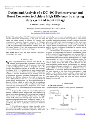
  • 1. International Journal of Scientific and Research Publications, Volume 10, Issue 6, June 2020 731 ISSN 2250-3153 This publication is licensed under Creative Commons Attribution CC BY. http://dx.doi.org/10.29322/IJSRP.10.06.2020.p10285 www.ijsrp.org Design and Analysis of a DC -DC Buck converter and Boost Converter to Achieve High Efficiency by altering duty cycle and input voltage R. Abhishek * , Pallavi Zoting* , Purva Ragit * * Department of electronics and communication (ECE), VNIT-NAGPUR DOI: 10.29322/IJSRP.10.06.2020.p10285 http://dx.doi.org/10.29322/IJSRP.10.06.2020.p10285 Abstract- This paper explains DC to DC buck convertor and boost converter which cites the dependency of duty cycle and input voltage on output voltage. It consists of elements like switch/mosfet, transistor, inductor, resistors. A NGSpice simulation has been conducted to analyze the efficiency of the DC-DC buck converter and boost converter. The result shows the efficiency of the DC-DC buck and boost converter increases as we increase the duty cycle and the input voltage. Index Terms- DC-DC buck and boost converter, ,efficiency , input voltage , duty cycle I. INTRODUCTION hile doing literature survey, we came across that DC- DC buck and boost converter was not designed with the help of switches, instead it was designed with the transistors. So, in order to form a novel project we decided to design this DC to DC convertor with the help of a switch. As we know that, to change the values of MOSFETs we had to alter the values of gate in order to get the output response. But in our case switch is used in place of MOSFET. This was the difficulty and the challenge which we incurred during our project simulation. As a solution to this we decided to give different voltages at the switch so that we can observe different ON and OFF time as per our desire which will fetch us buck or boost converter. This entire project simulation is done on NGSpice which is widely used for the simulation purpose. It consists of a very simple yet efficient interface. We can design very interesting circuits on this platform which can be a problem while trying to attempt all those circuits on some other platform. A DC power offer is employed in most of the appliances wherever a relentless voltage is needed. DC stands for electrical energy, during which the present flow is one-way. the method of DC conversion are often done by DC Converters. The charge carriers in DC offer travel in a very single direction. star cells, batteries and thermocouples square measure the sources of DC offer.. In AC offer the charge carriers modification their direction sporadically. AC offer is employed as utility current for home desires. A DC to DC device takes the voltage from a DC supply and converts the voltage of offer into another DC voltage level. they're wont to increase or decrease the voltage level. this is often unremarkably used cars, moveable chargers and moveable optical disk players. Some devices want an exact quantity of voltage to run the device. an excessive amount of of power will destroy the device or less power might not be ready to run the device. The device takes the ability from the battery and cuts down the voltage level, equally a device change of magnitude the voltage level. for instance, it would be necessary to step down the ability of an oversized battery of 24V to 12V to run a radio. The device takes the ability from the battery and cuts down the voltage level, equally a device change of magnitude the voltage level. for instance, it would be necessary to step down the ability of an oversized battery of 24V to 12V to run a radio.The Buck device represented in Power provides Module three.1 produces a DC output in an exceedingly vary from 0V to simply but the input voltage. The boost device can turn out associate output voltage starting from identical voltage because the input, to grade abundant over the input.There square measure several applications but, like powered systems, wherever the input voltage will vary wide, beginning at full charge and bit by bit decreasing because the battery charge is employed up. At full charge, wherever the battery voltage is also over truly required by the circuit being supercharged, a buck regulator would be ideal to stay the availability voltage steady. but because the charge diminishes the input voltage falls below the extent needed by the circuit, and either the battery should be discarded or re-charged. II. OPERATION i. DC-DC buck converter Circuit configuration of a DC-DC buck converter using switch. Fig. 1.1 DC-DC buck converter circuit configuration W
  • 2. International Journal of Scientific and Research Publications, Volume 10, Issue 6, June 2020 732 ISSN 2250-3153 This publication is licensed under Creative Commons Attribution CC BY. http://dx.doi.org/10.29322/IJSRP.10.06.2020.p10285 www.ijsrp.org In a DC to DC buck converter the output voltage is lower than the input voltage i.e. step down chopper. Vout = K x Vin where k= (TON/T)
  • 3. International Journal of Scientific and Research Publications, Volume 10, Issue 6, June 2020 733 ISSN 2250-3153 This publication is licensed under Creative Commons Attribution CC BY. http://dx.doi.org/10.29322/IJSRP.10.06.2020.p10285 www.ijsrp.org When the switch is turned off, a free wheeling diode is used to allow the load current to flow through it,. Due to the load inductance, the load current must be allowed a path, which is provided by the diode .In the absence of the diode it may cause damage to the switching device like MOSFET due to the high induced emf of the inductance. During the ON period (TON ≥ t ≥ 0), the output voltage is same as the input voltage i.e. v0 = Vs. ( The ON period is TON).During the OFF period (T ≥ t ≥ TON), the output voltage is zero i.e. v0 = 0 and diode DF starts conducting. ( The OFF period is TOFF = T-TON).The total time period is T = TON +TOFF and the frequency is f= 1/T. The duty ratio is k= (TON/T) = [TON/(TON/(TON+TOFF))], its range being 1.0≥k≥0.0. Circuit configuration of a DC-DC buck converter using MOSFET. Fig. 1.2 DC-DC buck converter circuit configuration A variable dc output voltage is obtained from a constant dc input voltage. A buck converter (dc-dc) is shown in Fig. 1.1 Only a switch is shown, for which a device as described earlier belonging to transistor family is used. The load is inductive (R- L) one. Resistor is connected in parallel with capacitor to discharge it. Due to the load inductance, the current across load must be allowed a path, which is provided by the diode; otherwise, i.e., in the absence of the above diode, due to the high induced emf of the inductance load current decrease, may cause damage to the switching device. ii. DC-DC boost converter Circuit configuration of a DC-DC boost converter using MOSFET. Fig. 2.1 DC-DC boost converter circuit configuration The load is resistive and inductive (R-L) type, in which the inductance of the load is small.. Initially during the ON period (TON ≥ t ≥ 0), The output voltage is zero (V0=0). The switch S is kept OFF during the period T ≥ t ≥ TON, where the OFF period is TOFF = T – TON . A boost converter (dc-dc) is shown in Fig. Normally transistor is used as a switch. Also, a diode is used in series with the load. The load is of the same type as given earlier. An inductance, L is assumed in series with the input supply. The position of the switch and diode is different as compared to their position in the buck converter. The operation of the circuit is explained as follows. Firstly, the switch, S (i.e., the device) is put ON (or turned ON) during the period . If no battery (back emf) is connected in series with the load,output voltage is zero and also as stated earlier. The current from the source flows in the inductance L. The value of current increases linearly with time in this interval, with being positive. As the current through L increases, the polarity of the induced emf is taken as positive. III. EXPRESSION FOR THE DC-DC BUCK AND BOOST CONVERTER i. DC-DC BUCK CONVERTER the average value of the output voltage is ii. DC-DC BOOST CONVERTER The average value of the output voltage II. PERFORMANCE OF THE DC-DC Buck AND Boost CONVERTER i. DC-DC BUCK CONVERTER The converter is designed by using NGSPICE. The converter is arranged by 10V input DC source. MOSFET switch which is considered as a switching device where the switching frequency has been set to 50KHz, as well as inductors L1 set at 50uH, load resistance RL 5Ω and output filter capacitor CL at 25µF. Table below represents the specifications of the circuit. In a DC to DC buck converter the output voltage is higher than the input voltage i.e. step up chopper.
  • 4. International Journal of Scientific and Research Publications, Volume 10, Issue 6, June 2020 734 ISSN 2250-3153 This publication is licensed under Creative Commons Attribution CC BY. http://dx.doi.org/10.29322/IJSRP.10.06.2020.p10285 www.ijsrp.org Table 1 Specification of the buck converter. Input DC Voltage Vin = 10V Inductor L1 = 50uH Capacitor CL = 50u Resistor RL = 5Ω
  • 5. International Journal of Scientific and Research Publications, Volume 10, Issue 6, June 2020 735 ISSN 2250-3153 This publication is licensed under Creative Commons Attribution CC BY. http://dx.doi.org/10.29322/IJSRP.10.06.2020.p10285 www.ijsrp.org A.Result from ngspice Simulation : The waveform plot presented in Fig. shows the simulation result of the DC-DC buck converter. Simulation result Fig shows output voltage received from the simulation is significantly smaller than the input signal. The fig containing currents passing through diodes D inductors L capacitor CL and resistor RL respectively. Here the input voltage 10V and the output voltage 8V and efficiency 83.79% GRAPHS: V(1) Input Voltage V(3) Output Voltage Output current B.Quantitative Comparison Variation of Voltage gain and efficiency with respect to duty cycle Table 1 below shows the comparative analysis between DC- DC buck converter under duty cycle and voltage gain variation, where circuits are switched at 50kHz means total time is 20us. When circuits are performing under duty variation, the switching frequency 50kHz fixed for buck circuit and other paramters also fixed. The comparison analysis between efficiency verses duty cycle variation of DC-DC buck converter shows that as we increases the duty cycle the efficiency increases. We get maximum efficiency of 83.93 at 100%duty cycle. Table 1 Performance Comparison under Duty Cycle Variation of Voltage gain with respect to duty cycle Current across inductor Voltage gain=output voltage/input voltage From above graph,Voltage gain increases with increase in value of duty cycle.
  • 6. International Journal of Scientific and Research Publications, Volume 10, Issue 6, June 2020 736 ISSN 2250-3153 This publication is licensed under Creative Commons Attribution CC BY. http://dx.doi.org/10.29322/IJSRP.10.06.2020.p10285 www.ijsrp.org Variation of efficiency with duty cycle Efficiency of Buck conveter is increases with increase in the value of duty cycle.maximum efficiency is for 100% duty cycle . As for 100% duty cycle output volteg should be equal to that of input voltage.But here output voltage is coming out to be 16.8 V and with 84% efficiency. Variation of efficiency for different amplitude in different duty cycles Moreover, Table 2 below shows the comparison between duty cycle and voltage gain for conventional DC-DC boost converter where switching frequency is kept at 10kHz. Furthermore, the ratio between duty cycle and voltage gain of proposed circuit indicated below. Table 2 Performance Comparison under input voltage. ii. iii. iv. v. vi. vii. viii. ix. x. xi. xii. xiii. DC-DC BOOST CONVERTER The converter is designed by using NGSPICE. The converter is arranged by 10V input DC source. MOSFET switch which is considered as a switching device where the switching has been set to 10KHz, as well as inductors L1 set at 0.7mH, and output filter capacitor CL at 1nF. Table below represents the specifications of the circuit. Table 1 Specification of the boost converter. Input DC Voltage Vin = 10V Inductor L1 = L2 = 0.7mHH Capacitor CL = 1nF A..Result from ngspice Simulation The classical wave shapes presented in Fig. shows the simulation result of the DC-DC BOOST converter. Simulation result Fig shows output voltage received from the simulation is significantly larger than the input signal. The fig containing currents passing through diodes D inductors L capacitor CL respectively. Here the input voltage 10V and the output voltage 12.8V and efficiency 95.5% GRAPHS: V(1) Input Voltage V(3) Output Voltage V(3) Output Voltage
  • 7. International Journal of Scientific and Research Publications, Volume 10, Issue 6, June 2020 737 ISSN 2250-3153 This publication is licensed under Creative Commons Attribution CC BY. http://dx.doi.org/10.29322/IJSRP.10.06.2020.p10285 www.ijsrp.org B.Quantitative Comparison variation of efficiency with duty cycle: variation of voltage gain with duty cycle: IV. CONCLUSION A buck and boost DC to DC converter can be used for the purpose of increasing the output voltage according to the variation in the duty cycle and the input voltage. In this operation, buck boost converter provides step down output voltage and the total circuit has drawn by using the same element of conventional DC-DC buck converter. It can be concluded from the results of DC-DC buck and boost converter output simulations performs better with variation of duty cycle. It is also seen that with increase in duty cycle, there is magnificent increase in efficiency. Not only that, we get a tremendous increase in the voltage gain too. The novelty of this project is we can get high and low voltage as per our application with maximum efficiency. This circuit can efficiently work for DC power supply appliances where a constant voltage is required. There is no such significant increase in output current when we increase the input voltage in Buck converter. This can be surely viewed as a novelty. The proposed DC-DC buck and boost converter will be suitable to use in audio and instrumentation amplifier, line drivers and receivers. variation of input amplitude for 50%duty cycle ACKNOWLEDGMENT Our sincere gratefulness to the Professor of ECE department of VNIT, Prof. Ganesh Patil for their motivation to do research level project in device modelling. REFERENCES [1] Power Electronics: Principles and Applications by Joseph Vithayathil [2] Power Electronics by Muhammad H. Rashid [3] Power Electronics and Drives by Ned Mohan [4] Thyristorised Power Controllers by G. K. Dubey [5] Jefferson M. de Sousa et al, High voltage gain Buck-Boost DC- DC converter, “IEEE Transactions on Power Electronics Year: 2015 [6] [6 ] Neng Zhang et al, A buck-boost converter based multi-input DC- DC/AC converter, “IEEE Transactions on Power Electronics Year: 2017 [7] Jing Li et al, A Novel Buck–Boost Converter With Low Electric Stress ,” IEEE Transactions on Industrial Electronics Year: 2018 [8] Sairatun Nesa Soheli et al, Design and Analysis of a DC -DC Buck Boost Converter to Achieve High Efficiency and Low Voltage Gain by using Buck Boost Topology into Buck Topology, “IEEE Transactions on Power Electronics Year: 2018
  • 8. International Journal of Scientific and Research Publications, Volume 10, Issue 6, June 2020 738 ISSN 2250-3153 This publication is licensed under Creative Commons Attribution CC BY. http://dx.doi.org/10.29322/IJSRP.10.06.2020.p10285 www.ijsrp.org AUTHORS First Author – R. Abhishek, Department of electronics and communication (ECE), VNIT-NAGPUR, abhishek16021999@gmail.com Second Author – Pallavi Zoting, department of electronics and communication (ECE), VNIT-NAGPUR, pallavizoting99@gmail.com Third Author – Purva Ragit, Department of electronics and communication (ECE), VNIT-NAGPUR, purvaragit@gmail.com