OPEN CIRCUIT AND SHORT CIRCUIT TEST OF SINGLE PHASE TRANSFORMER|DAY7| BASIC ELECTRICAL ENGINEERING

#Open_circuit_short_circuit_test of single phase transformer #OC_SC_TEST OF TRANSFORMER #Core loss and copper loss test of single phase transformer. After going through this session you will be able to answer the following questions. • Which parameters are obtained from O.C test? • Which parameters are obtained from S.C test? • What percentage of rated voltage is needed to be applied to carry out O.C test? • What percentage of rated voltage is needed to be applied to carry out S.C test? • From which side of a large transformer, would you like to carry out O.C test? • From which side of a large transformer, would you like to carry out S.C test? Aim of conduction transformer Open Circuit & Short Circuit test To predict its performance without actual loading. Determination of equivalent circuit parameters To determine parameters of a transformer like voltage regulation and efficiency Open circuit test is carried out to determine core loss and shunt parameters. Open circuit test is carried out at rated voltage and rated frequency . During this test, rated flux is produced in the core . To carry out open circuit test rated voltage at rated frequency is applied to LV side of the transformer and HV side is left opened as shown in the circuit diagram. HV side is left opened because it is easier to arrange rated voltage supply on LV side because no load current which is quite small about 2 to 5% of the rated current. Metering instrument connected at LV side are economical & always safer to work. The voltmeter, ammeter and the wattmeter readings are taken and suppose they are Voc , Io and Poc respectively. Strictly speaking the wattmeter will record the core loss as well as the LV winding copper loss. But the winding copper loss is very small compared to the core loss as the flux in the core is rated.

Recommended
More Related Content
What's hot
What's hot (20)
Similar to OPEN CIRCUIT AND SHORT CIRCUIT TEST OF SINGLE PHASE TRANSFORMER|DAY7| BASIC ELECTRICAL ENGINEERING
Similar to OPEN CIRCUIT AND SHORT CIRCUIT TEST OF SINGLE PHASE TRANSFORMER|DAY7| BASIC ELECTRICAL ENGINEERING (20)
More from Prasant Kumar
More from Prasant Kumar (20)
Recently uploaded
Recently uploaded (20)
OPEN CIRCUIT AND SHORT CIRCUIT TEST OF SINGLE PHASE TRANSFORMER|DAY7| BASIC ELECTRICAL ENGINEERING
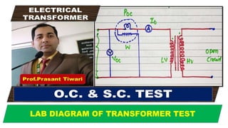
- 1. Prof.Prasant Tiwari ELECTRICAL TRANSFORMER LAB DIAGRAM OF TRANSFORMER TEST
- 2. OPEN CIRCUIT & SHORT CIRCUIT TEST Aim of conduction transformer Open Circuit & Short Circuit test To predict its performance without actual loading. Determination of equivalent circuit parameters To determine parameters of transformer like voltage regulation and efficiency. After going through this session you will be able to answer the following questions. • Which parameters are obtained from O.C test? • Which parameters are obtained from S.C test? • What percentage of rated voltage is needed to be applied to carry out O.C test? • What percentage of rated voltage is needed to be applied to carry out S.C test? • From which side of a large transformer, would you like to carry out O.C test? • From which side of a large transformer, would you like to carry out S.C test?
- 3. OPEN CIRCUIT TEST To carry out open circuit test rated voltage at rated frequency is applied to LV side of the transformer and HV side is left opened as shown in the circuit diagram. HV side is left opened because it is easier to arrange rated voltage supply on LV side because no load current which is quite small about 2 to 5% of the rated current. Metering instrument connected at LV side are economical & always safer to work. The voltmeter, ammeter and the wattmeter readings are taken and suppose they are Voc , Io and Poc respectively. Strictly speaking the wattmeter will record the core loss as well as the LV winding copper loss. But the winding copper loss is very small compared to the core loss as the flux in the core is Open circuit test is carried out to determine core loss and shunt parameters. Open circuit test is carried out at rated voltage and rated frequency . During this test, rated flux is produced in the core .
- 4. OPEN CIRCUIT TEST Poc = Core loss in watts Voc = Rated supply voltage Io = No load current Ro = Fictitious resistance Xm = Magnetizing/fictitious reactance W =Wattmeter Im = Magnetizing current Iw = Active component of no Current
- 5. SHORT CIRCUIT TEST Short circuit test is carried out to determine copper loss & transformer Equivalent parameters. Short circuit test is carried out at rated current. It should be noted that voltage required to be applied for rated short circuit current is quite small (about 5%). All measuring instruments connected in HV side (Low current) of the transformer where rated current is applied and LV side is short circuited as shown in the circuit diagram. Metering instrument connected at low current(HV) side are economical & always safer to work. LV side is short circuited because it is easier to arrange low rated current on HV side because Supply voltage required is quite small about 2 to 5% of the rated voltage. The voltmeter, ammeter and the wattmeter readings are taken and suppose they are,Vsc Isc , Psc respectively. Strictly speaking the wattmeter will record the copper loss as well as the core loss. But the core loss is very small compared to the copper loss so it is neglected as the flux in the core is small.
- 6. SHORT CIRCUIT TEST Psc = Copper loss in watts Vsc = supply voltage Isc = Rated SC current Req = Equivalent resistance Xeq = Equivalent reactance V,A &W =Voltmeter, Ammeter & Wattmeter
- 7. CAPSULES OF TRANSFORMER TEST To carry out open circuit test rated voltage at rated frequency is applied to LV side of the transformer and HV side is left opened as shown in the circuit diagram. HV side is left opened because it is easier to arrange rated voltage supply on LV side because no load current which is quite small about 2 to 5% of the rated current. Metering instrument connected at LV side are economical & always safer to work. The voltmeter, ammeter and the wattmeter readings are taken and suppose they are Voc , Io and Poc respectively. Strictly speaking the wattmeter will record the core loss as well as the LV winding copper loss. But the winding copper loss is very small compared to the core loss as the flux in the core is rated.