Download to read offline
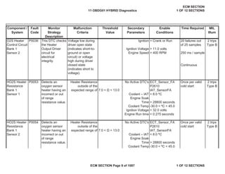
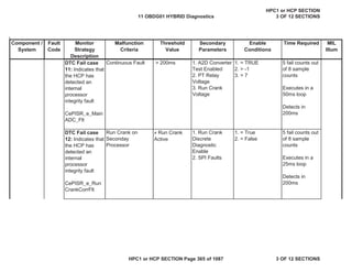
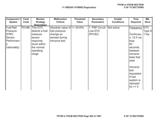
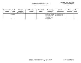
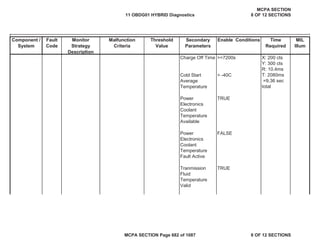
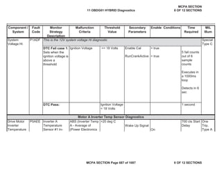
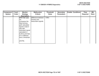
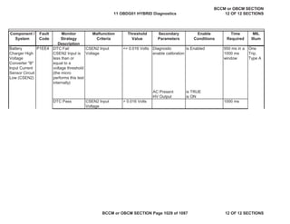
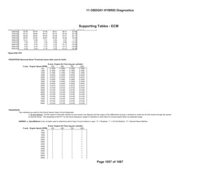
![Secondary
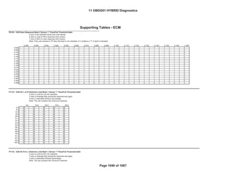
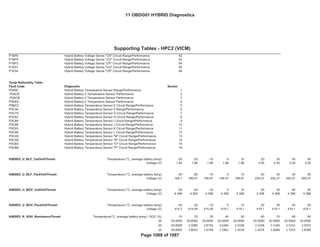
Parameters
Enable
Conditions
Time Required MIL
Illum
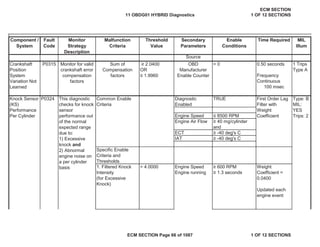
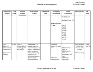
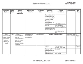
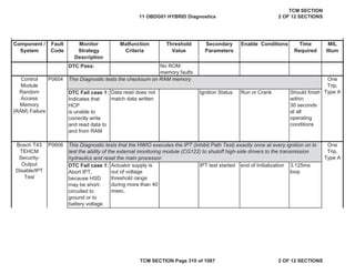
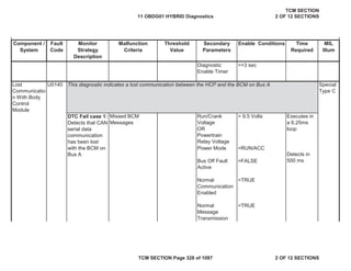
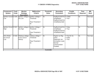
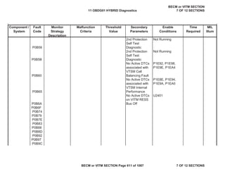
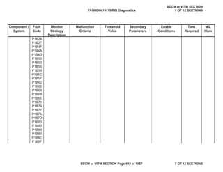
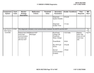
Component /
System
Fault
Code
Monitor
Strategy
Description
Malfunction
Criteria
Threshold
Value
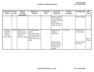
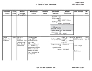
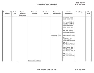
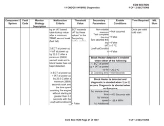
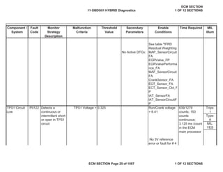
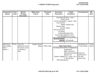
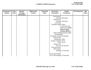
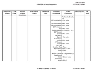
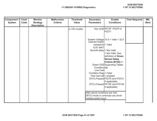
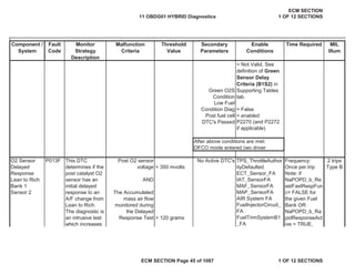
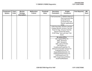
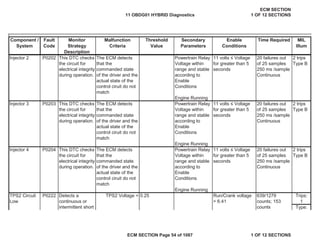
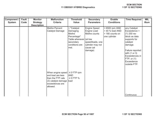
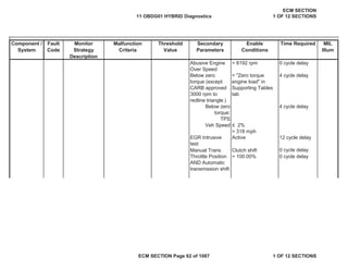
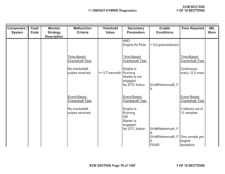
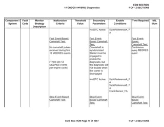
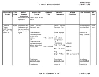
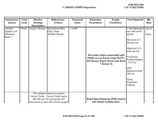
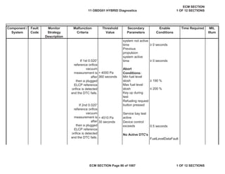
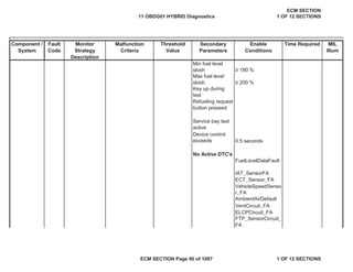
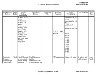
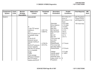
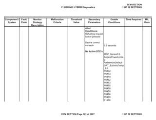
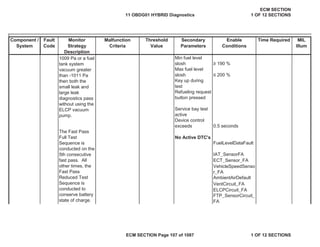
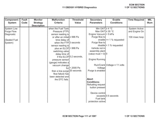
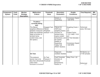
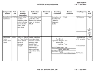
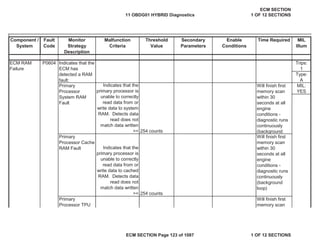
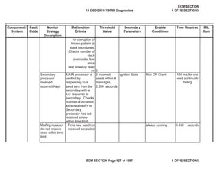
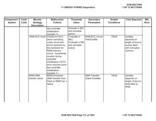
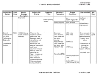
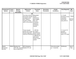
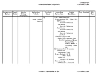
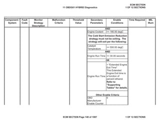
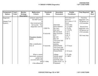
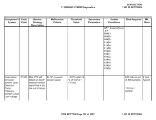
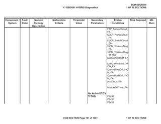
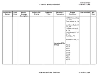
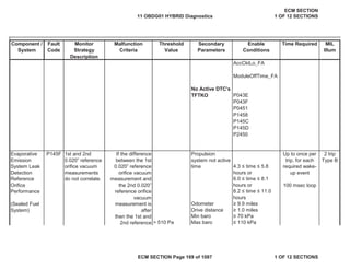
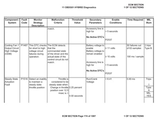
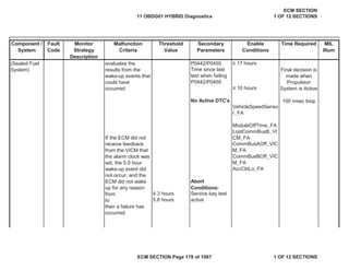
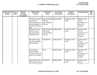
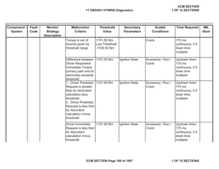
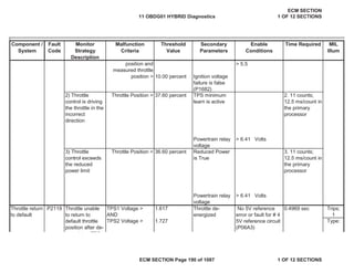
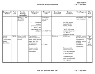
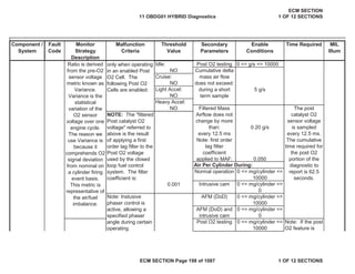
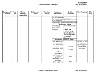
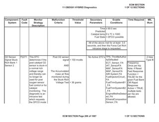
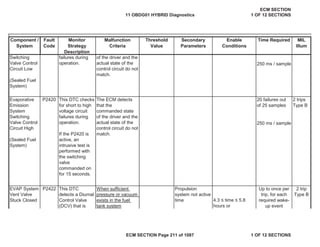
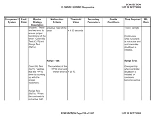
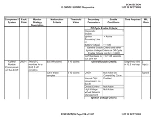
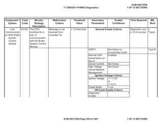
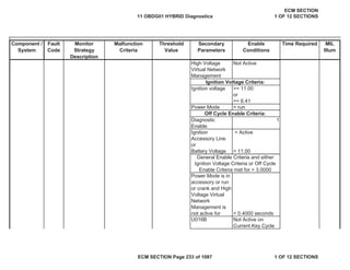
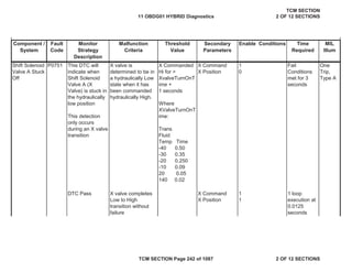
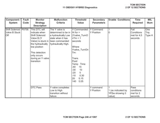
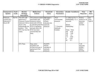
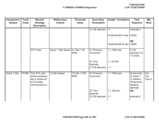
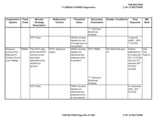
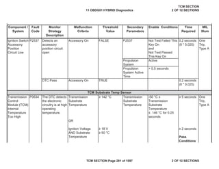
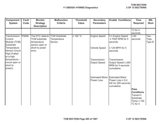
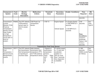
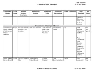
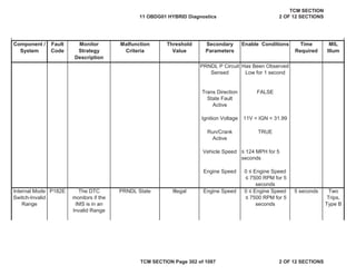
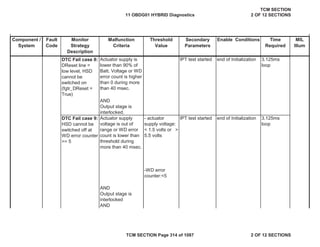
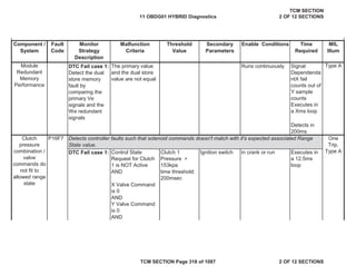
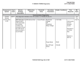
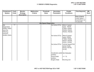
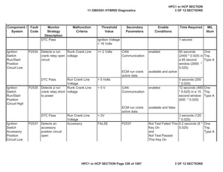
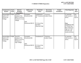
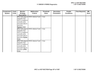
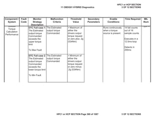
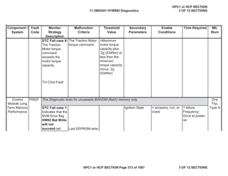
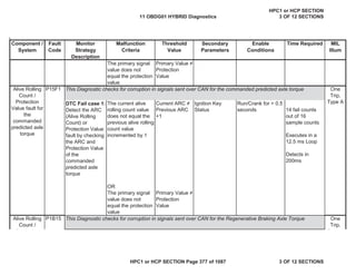
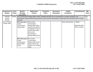
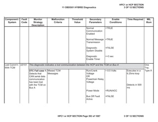
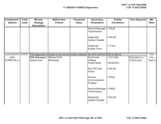
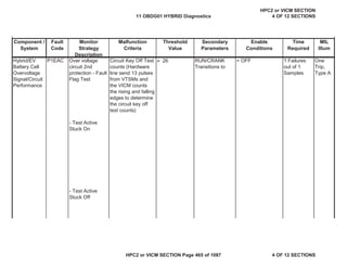
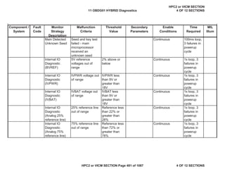
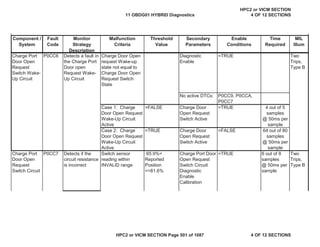
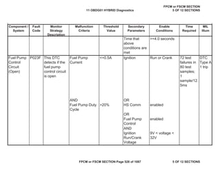
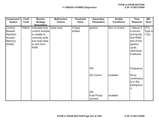
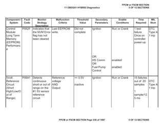
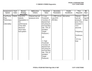
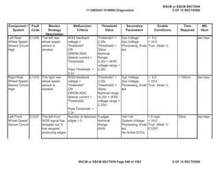
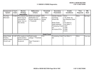
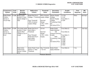
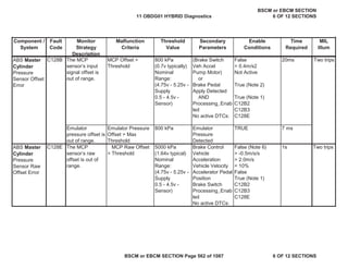
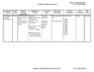
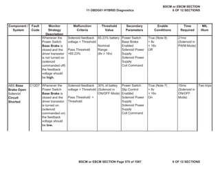
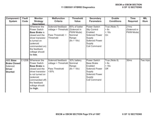
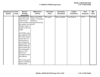
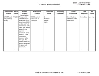
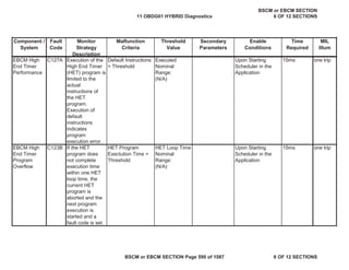
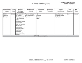
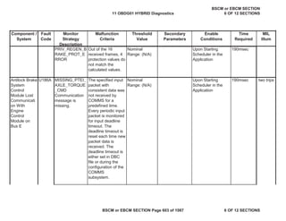
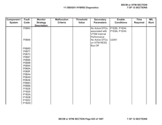
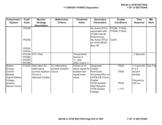
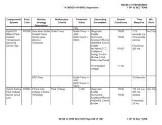
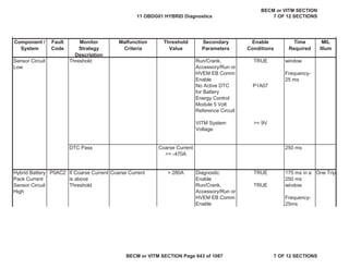
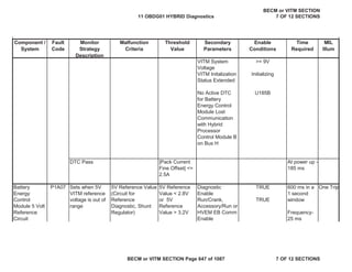
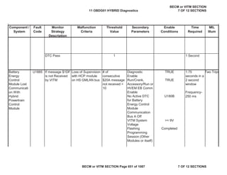
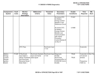
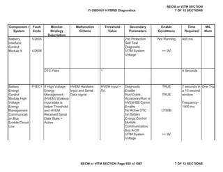
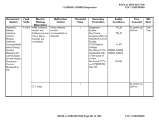
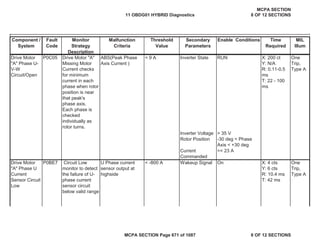
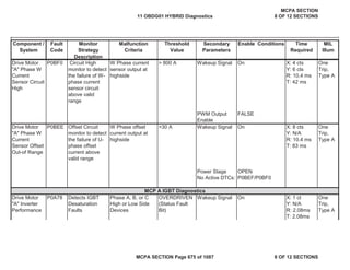
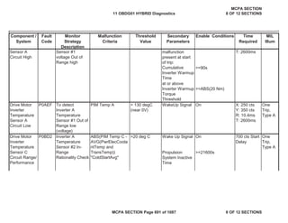
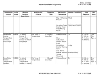
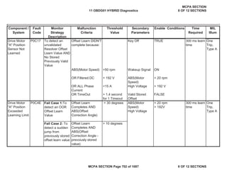
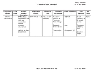
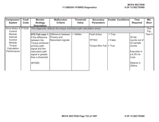
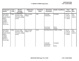
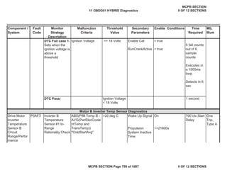
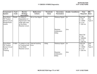
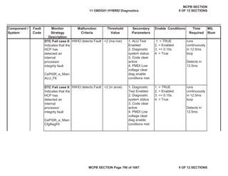
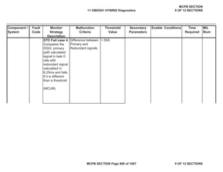
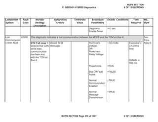
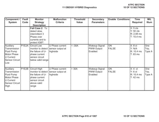
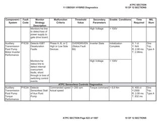
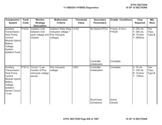
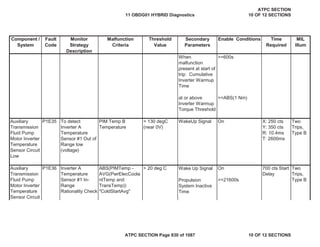
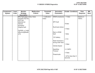
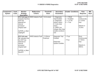
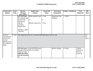
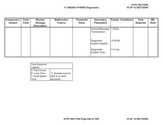
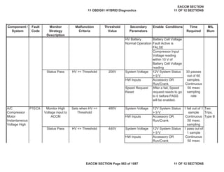
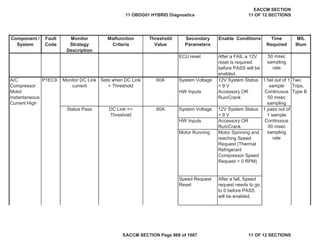
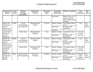
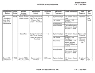
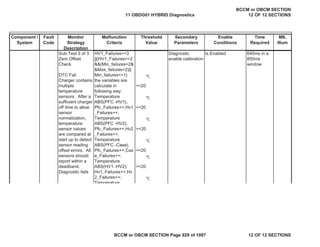
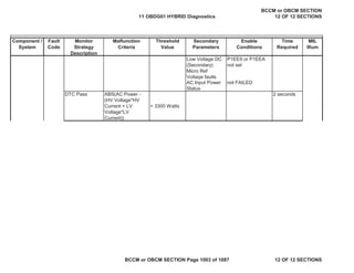
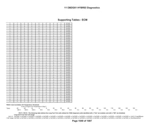
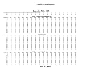
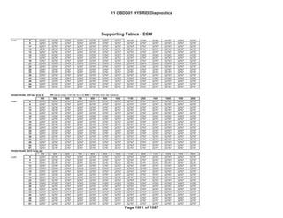
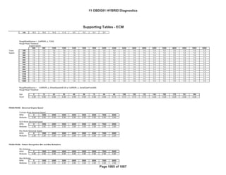
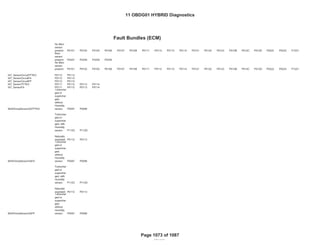
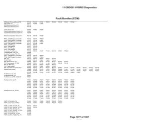
Detects a VVT
system error by
comparing the
desired and
actual cam
positions when
VVT is activated
Camshaft position
error [absolute
value of (desired
position - actual
position)] is
compared to
thresholds to
determine if
excessive
(Intake cam
Bank 1)Cam
Position Error >
KtPHSD_phi_C
amPosErrorLim
Ic1 Deg (see
Supporting
Table)
DTC’s are NOT
active:
P0010 IntkCMP
B1 Circuit
IntakeCamSenso
rTFTKO
CrankSensorTFT
KO
CrankIntakeCam
CorrelationFA
System Voltage >
11 Volts,
Both Desired &
Measured cam
positions cannot be
<
KtPHSD_phi_CamP
osErrorLimIc1 or >
than (29.0 -
KtPHSD_phi_CamP
osErrorLimIc1).
Desired cam
position cannot vary
more than 3.0 Cam
Deg for at least
KtPHSD_t_StableP
ositionTimeIc1
seconds (see
Supporting Tables)
135 failures out
of 150 samples
Trips 2
B Type
Intake
Camshaft
System
Performance
– Bank 1
P0011
11 OBDG01 HYBRID Diagnostics
ECM SECTION
1 OF 12 SECTIONS
ECM SECTION Page 3 of 1087 1 OF 12 SECTIONS](https://image.slidesharecdn.com/chevroletvolthybriddtc-230327065334-9b8d0d74/85/Chevrolet-Volt-Hybrid-DTC-3-320.jpg)
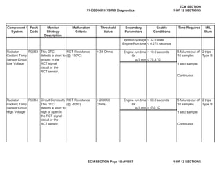
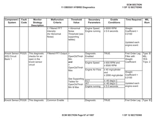
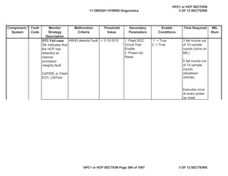
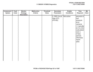
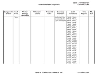
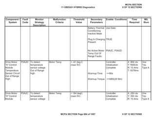
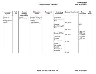
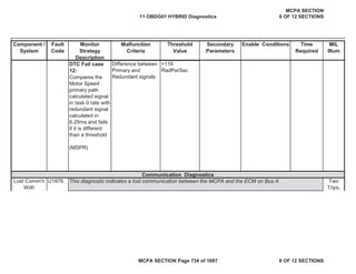
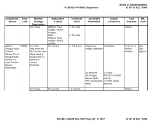
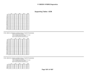
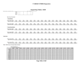
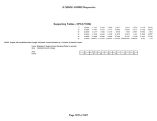
![Secondary
Parameters
Enable
Conditions
Time Required MIL
Illum
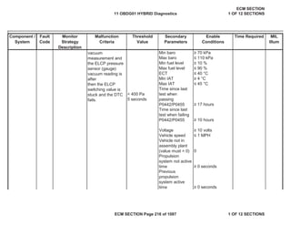
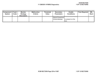
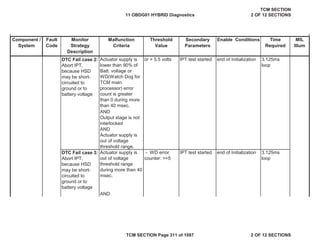
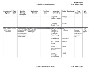
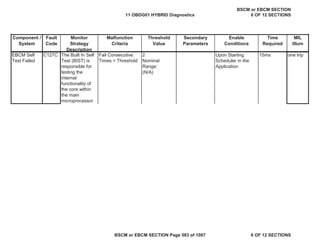
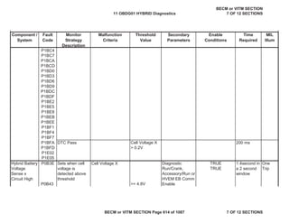
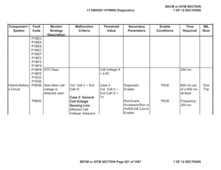
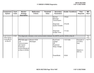
Component /
System
Fault
Code
Monitor
Strategy
Description
Malfunction
Criteria
Threshold
Value
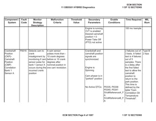
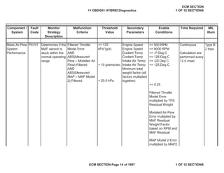
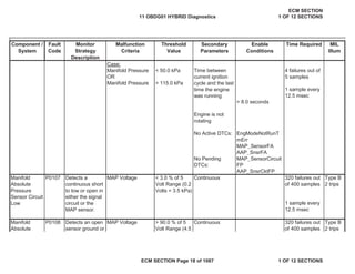
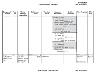
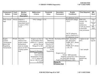
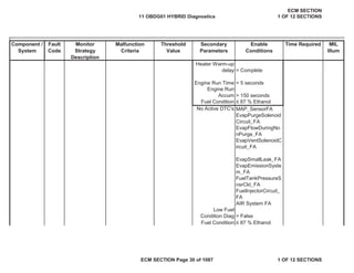
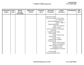
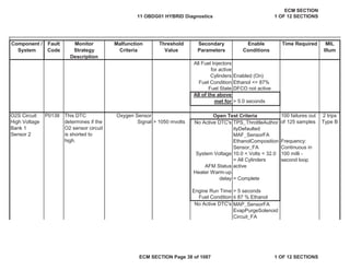
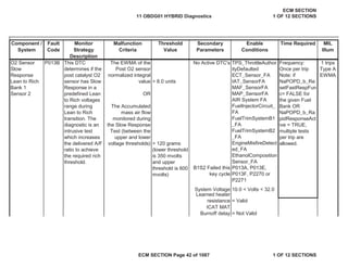
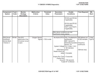
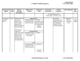
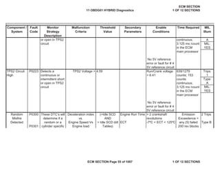
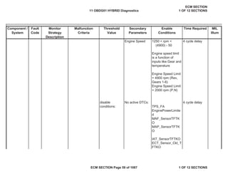
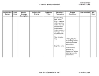
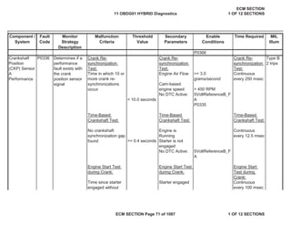
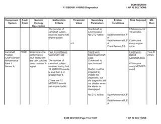
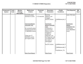
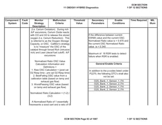
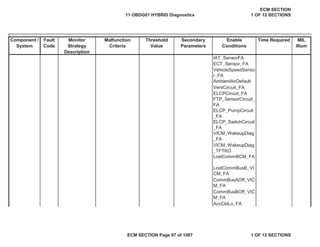
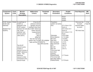
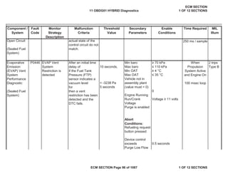
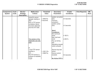
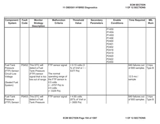
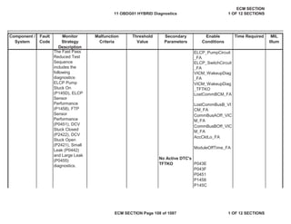
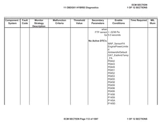
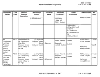
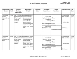
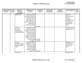
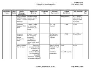
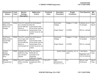
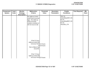
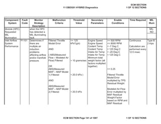
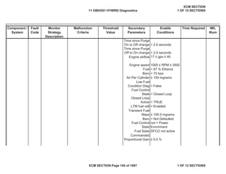
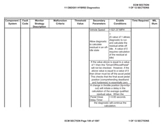
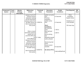
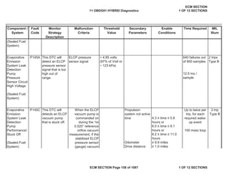
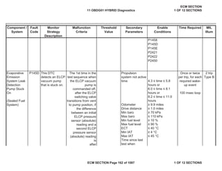
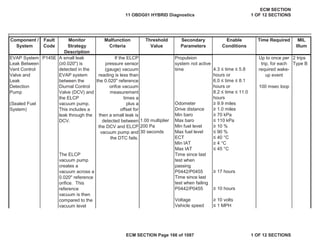
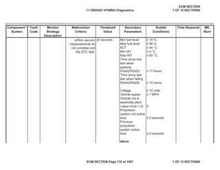
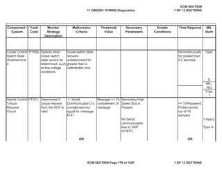
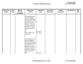
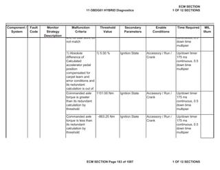
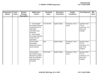
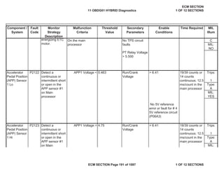
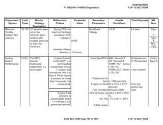
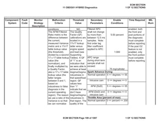
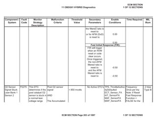
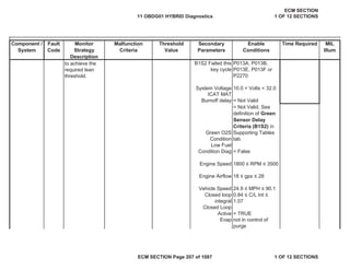
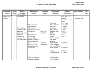
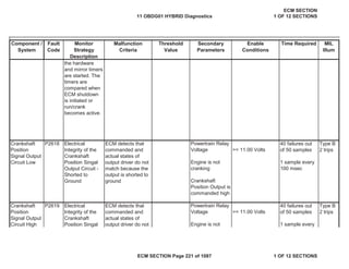
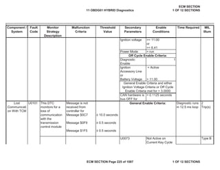
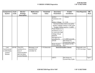
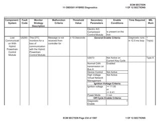
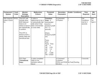
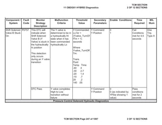
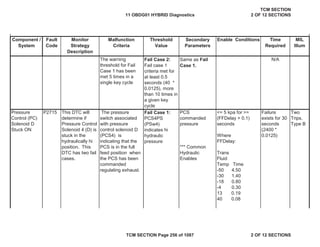
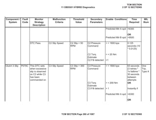
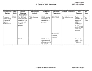
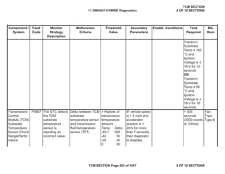
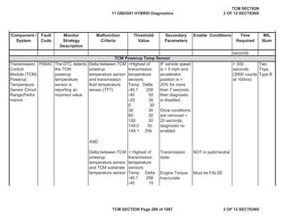
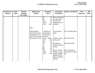
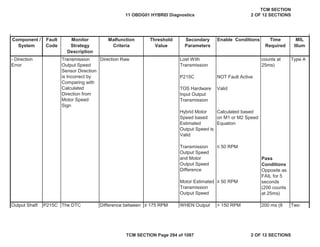
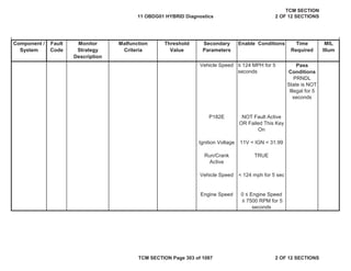
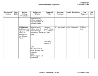
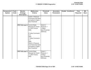
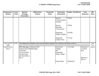
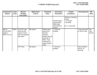
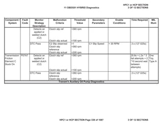
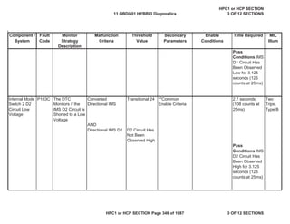
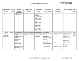
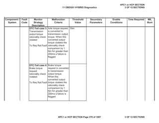
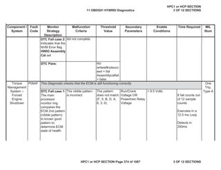
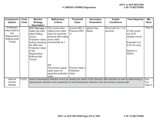
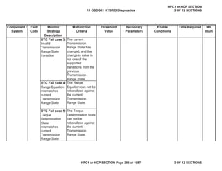
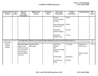
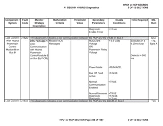
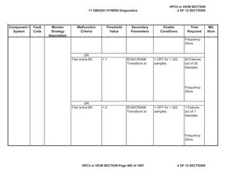
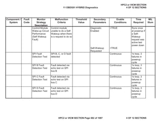
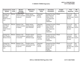
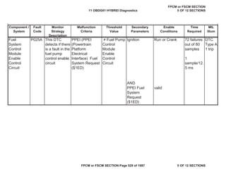
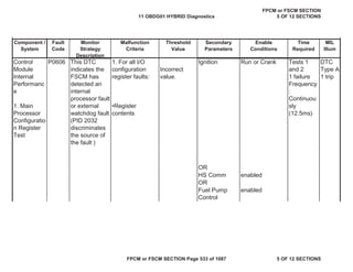
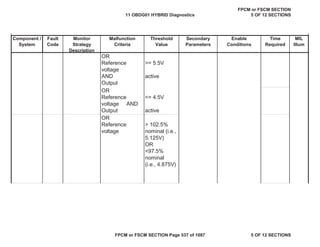
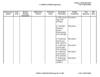
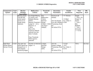
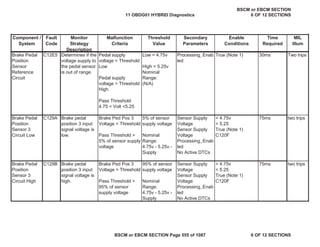
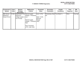
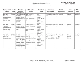
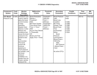
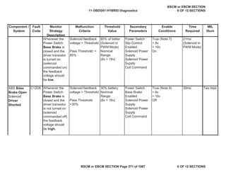
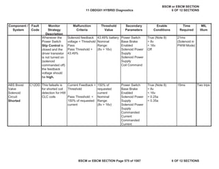
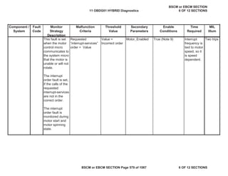
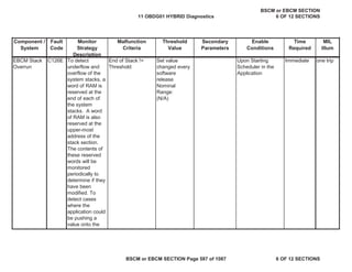
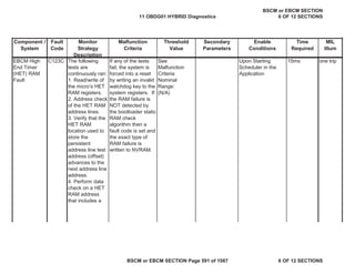
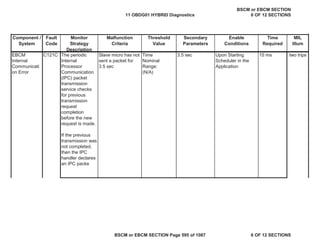
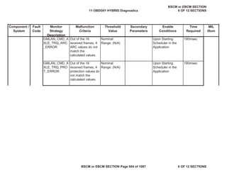
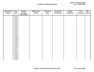
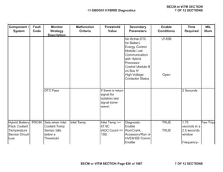
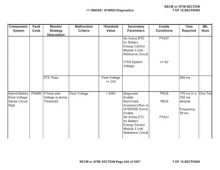
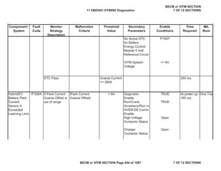
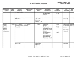
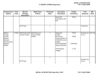
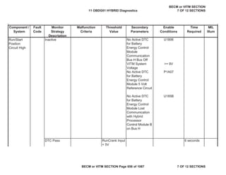
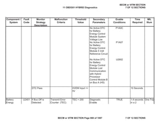
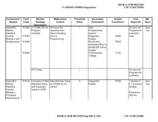
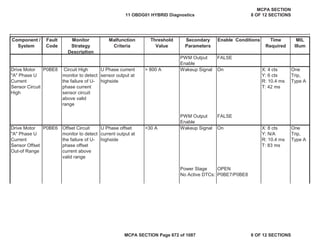
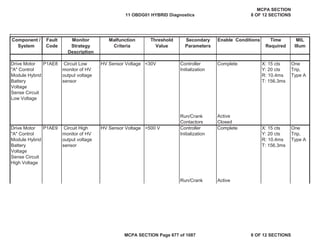
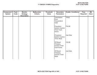
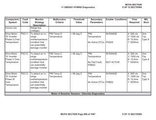
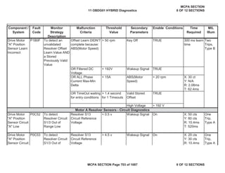
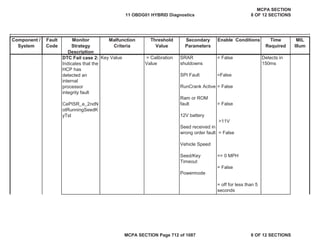
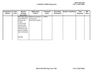
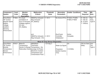
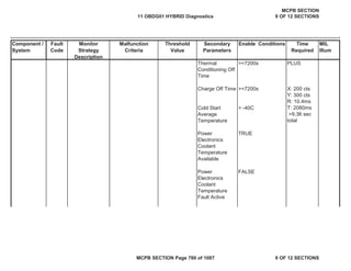
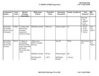
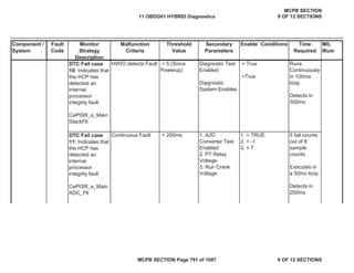
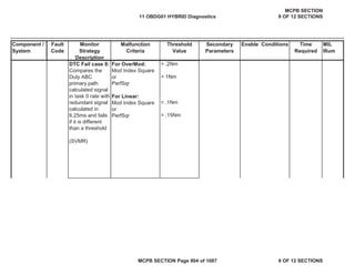
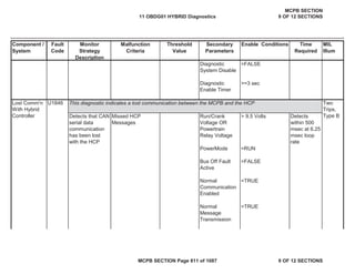
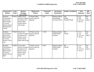
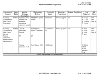
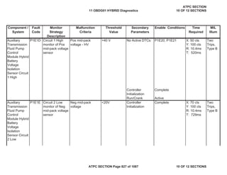
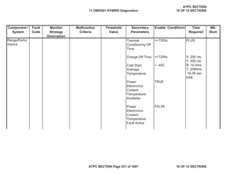
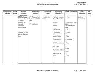
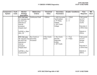
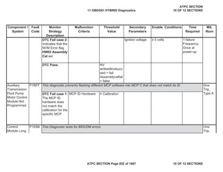
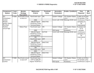
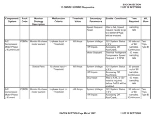
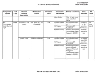
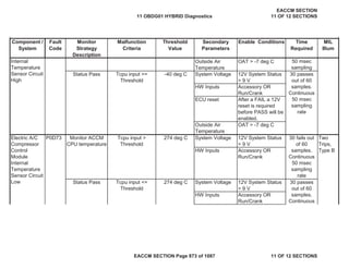
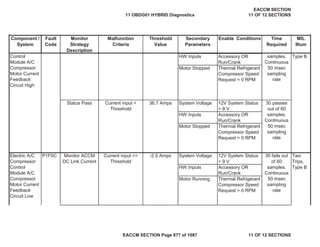
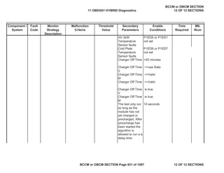
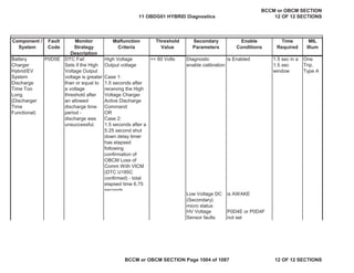
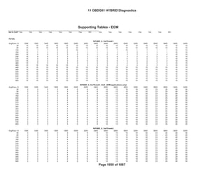
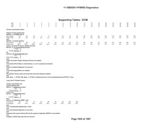
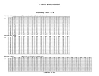
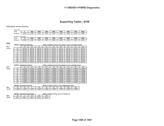
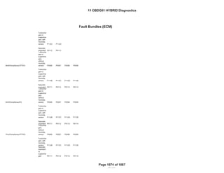
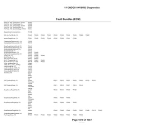
Detects a VVT
system error by
comparing the
desired and
actual cam
positions when
VVT is activated
Camshaft position
error [absolute
value of (desired
position - actual
position)] is
compared to
thresholds to
determine if
excessive
(Exhaust cam
Bank 1)Cam
Position Error >
KtPHSD_phi_C
amPosErrorLim
Ec1 Deg (see
Supporting
Table)
DTC’s are NOT
active:
P0013 IntkCMP
B1 Circuit
ExhaustCamSen
sorTFTKO
CrankSensorTFT
KO
CrankExhaustCa
mCorrelationFA
System Voltage >
11 Volts,
Both Desired &
Measured cam
positions cannot be
<
KtPHSD_phi_CamP
osErrorLimEc1 or >
than (Exh23.5 -
KtPHSD_phi_CamP
osErrorLimEc1).
Desired cam
position cannot vary
more than 3.0 Cam
Deg for at least
KtPHSD_t_StableP
ositionTimeEc1
seconds (see
Supporting Tables)
135 failures out
of 150 samples
Trips 2
B Type
Exhaust
Camshaft
System
Performance
– Bank 1
P0014
11 OBDG01 HYBRID Diagnostics
ECM SECTION
1 OF 12 SECTIONS
ECM SECTION Page 5 of 1087 1 OF 12 SECTIONS](https://image.slidesharecdn.com/chevroletvolthybriddtc-230327065334-9b8d0d74/85/Chevrolet-Volt-Hybrid-DTC-5-320.jpg)
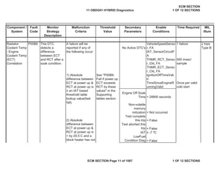


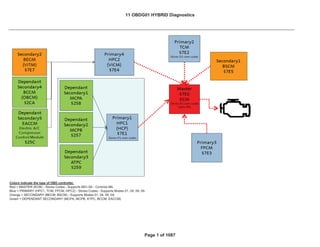
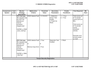
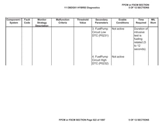
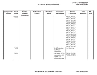
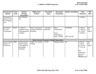
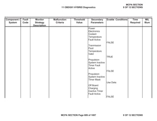
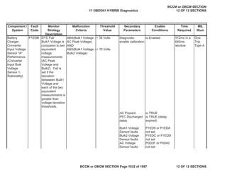
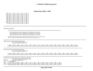
![Secondary
Parameters
Enable
Conditions
Time Required MIL
Illum
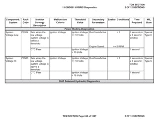
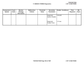
Component /
System
Fault
Code
Monitor
Strategy
Description
Malfunction
Criteria
Threshold
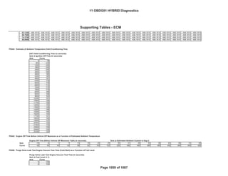
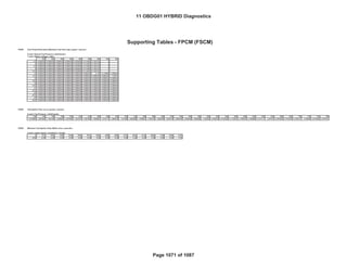
Value
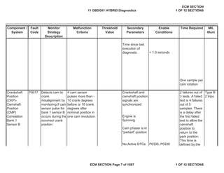
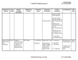
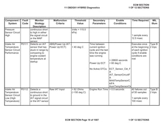
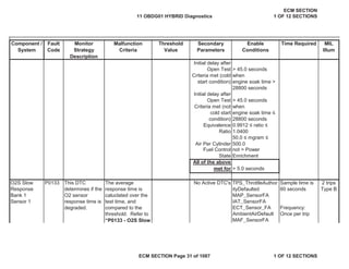
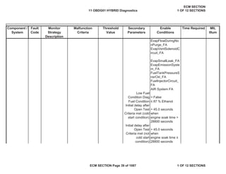
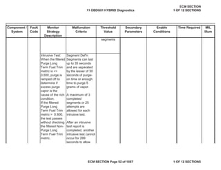
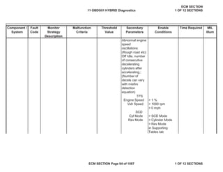
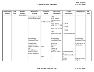
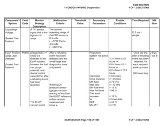
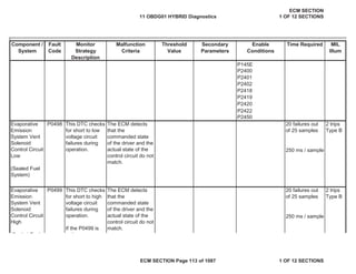
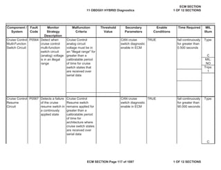
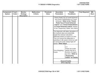
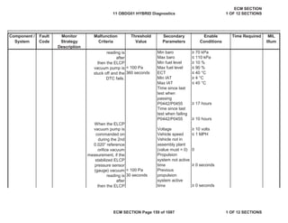
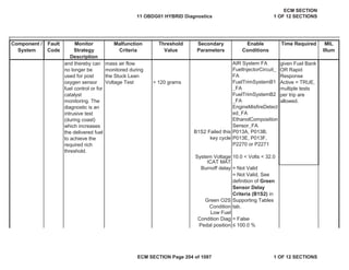
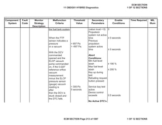
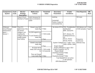
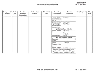
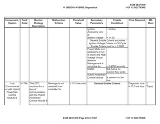
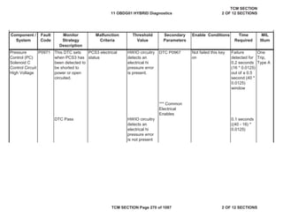
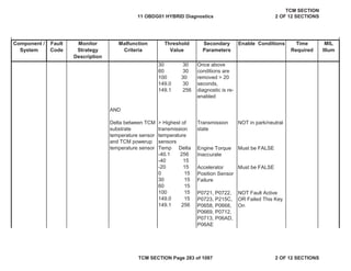
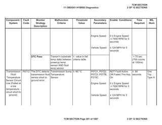
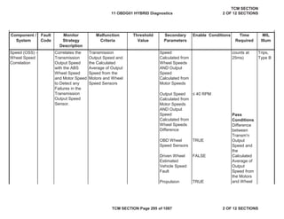
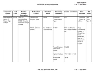
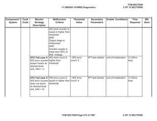
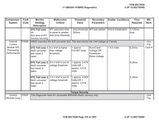
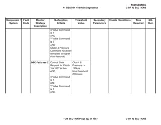
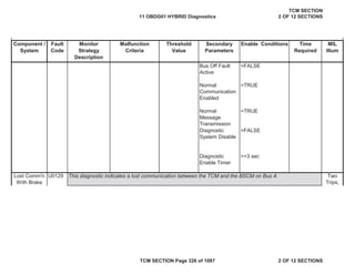
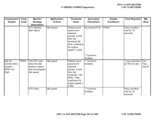
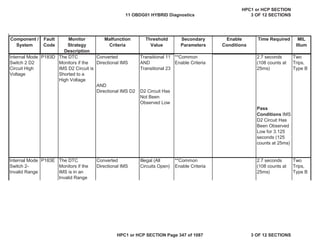
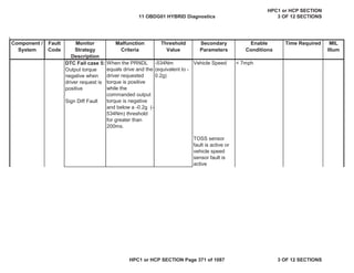
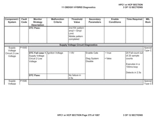
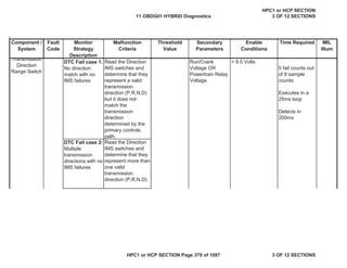
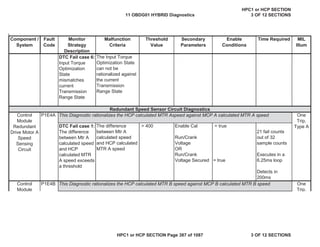
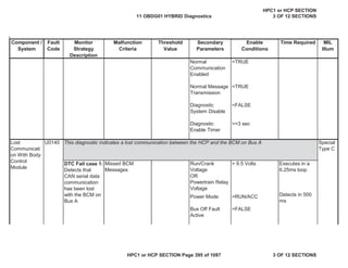
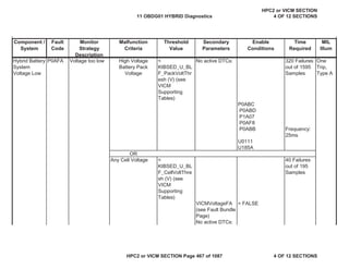
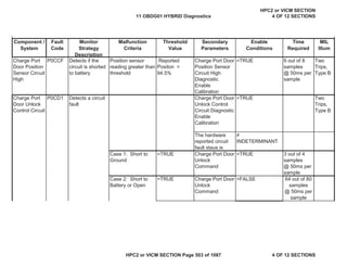
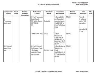
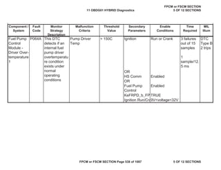
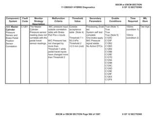
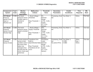
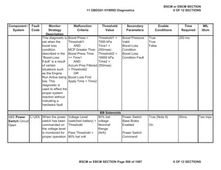
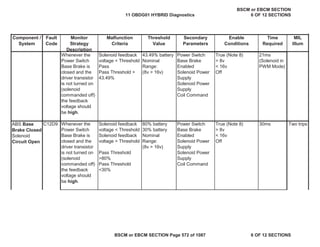
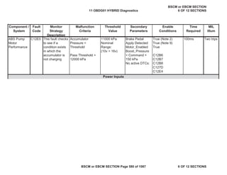
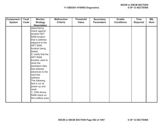
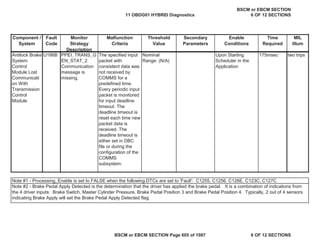
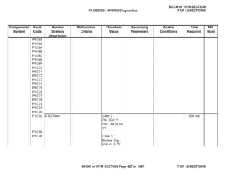
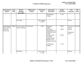
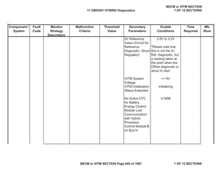
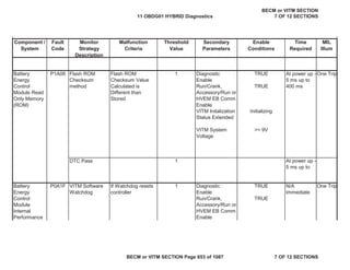
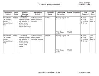
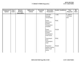
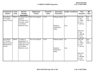
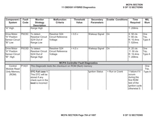
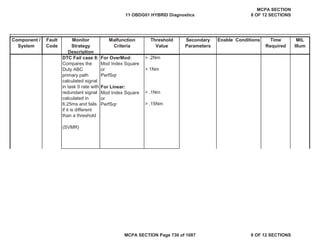
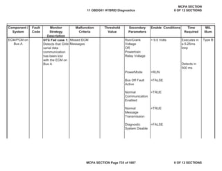
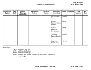
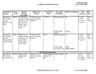
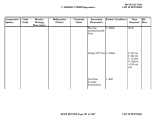
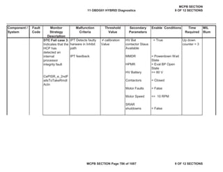
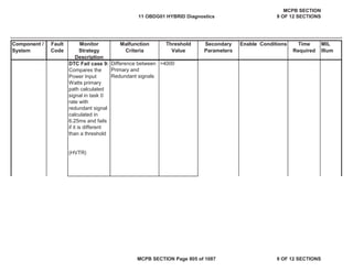
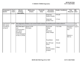
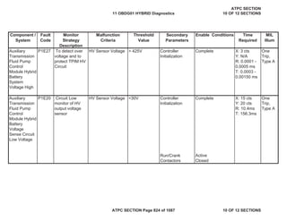
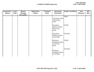
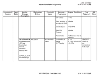
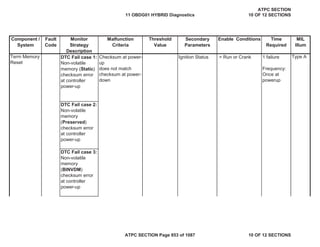
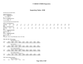
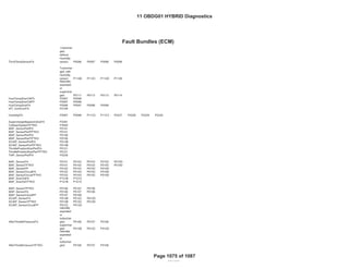
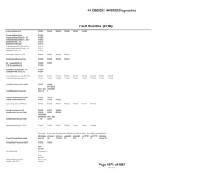
YES
Type A
1 trips
MIL:
NO
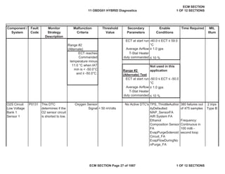
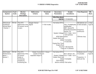
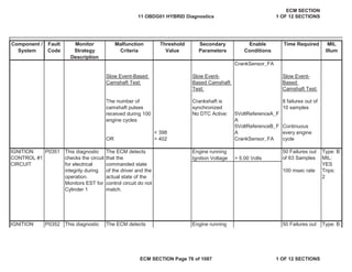
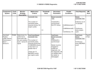
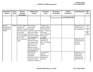
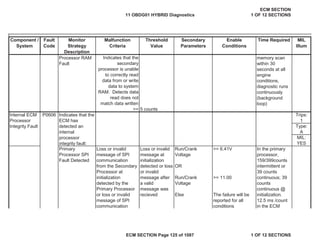
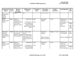
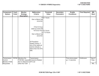
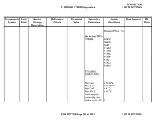
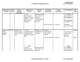
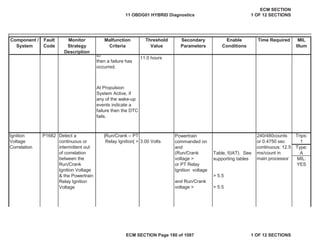
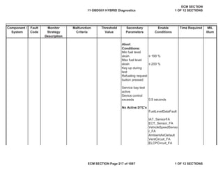
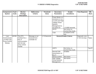
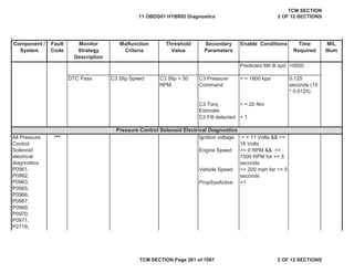
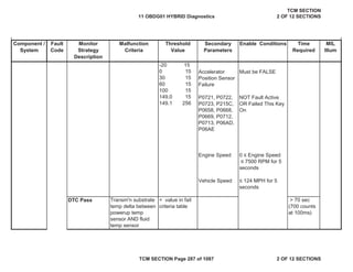
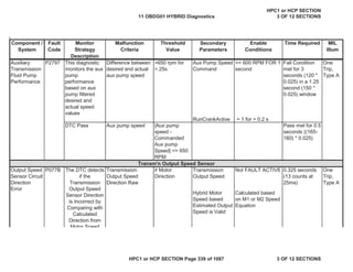
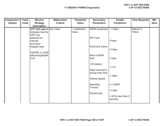
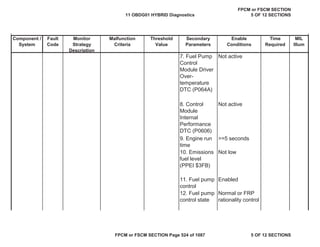
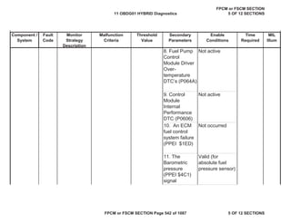
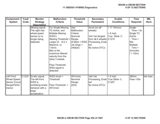
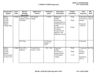
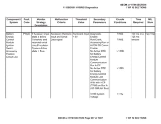
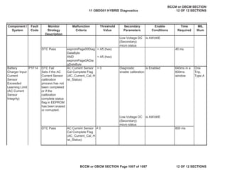
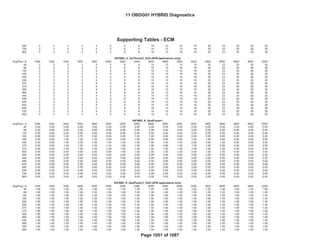
ECM Vref4 < 4.875 Run/Crank
Voltage
Trips:
or ECM Vref4 > 5.125 1
Type:
A
0.05 MIL:
YES
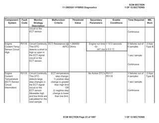
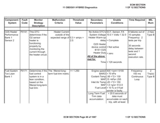
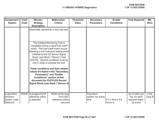
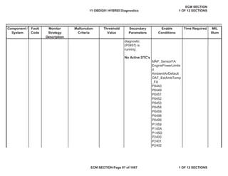
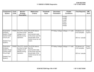
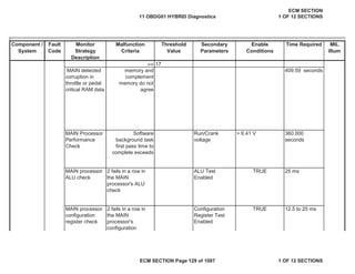
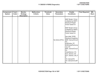
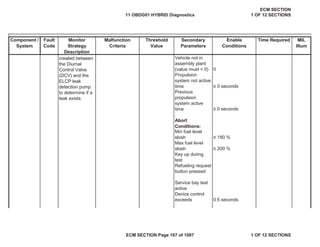
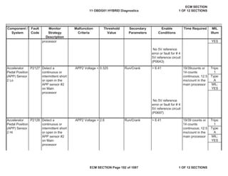
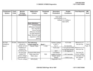
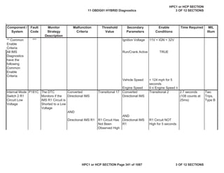
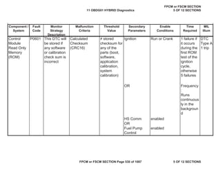
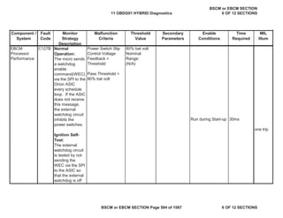
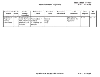
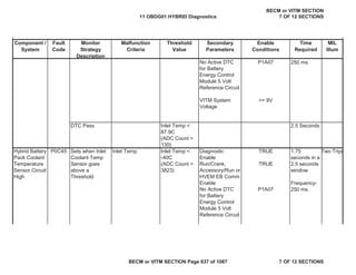
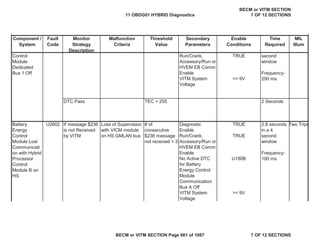
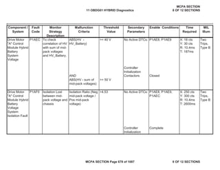
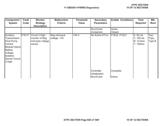
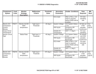
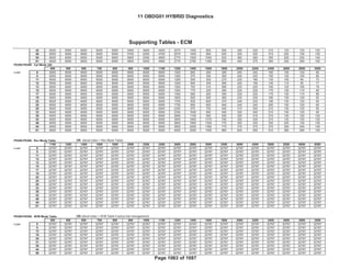
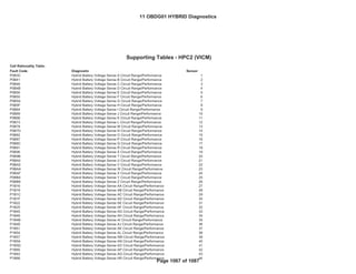
Engine Speed > 600 RPM and
< 5000 RPM
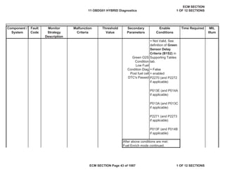
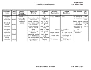
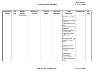
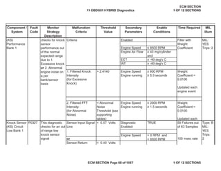
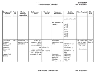
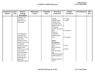
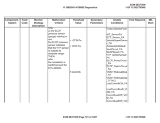
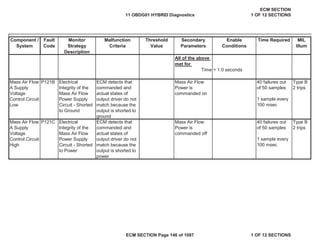
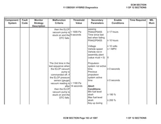
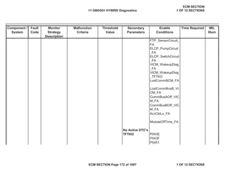
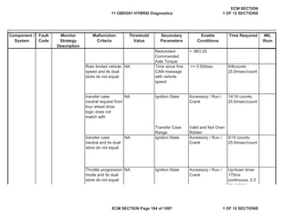
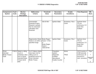
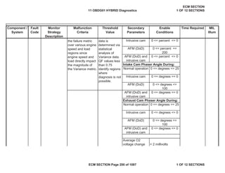
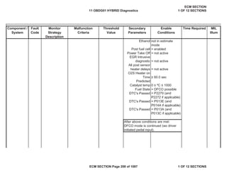
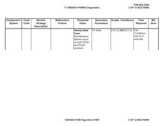
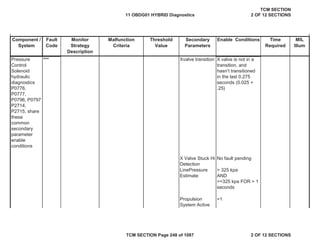
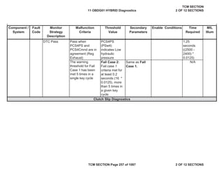
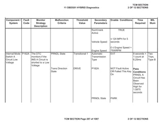
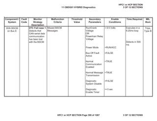
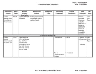
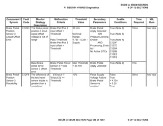
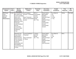
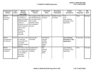
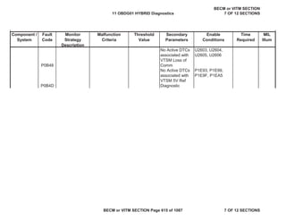
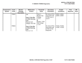
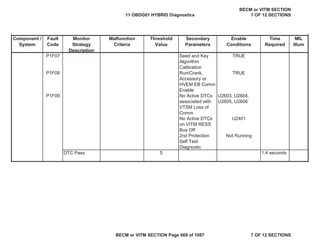
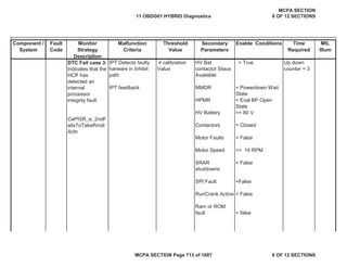
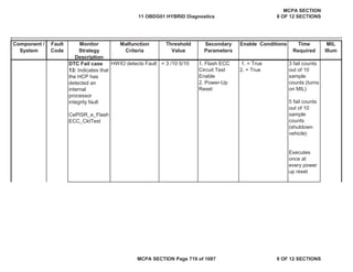
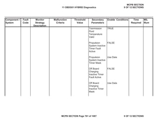
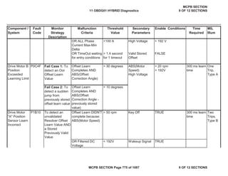
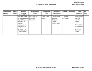
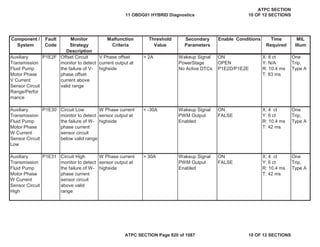
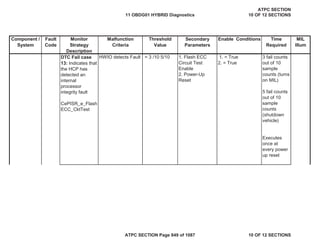
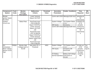
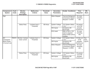
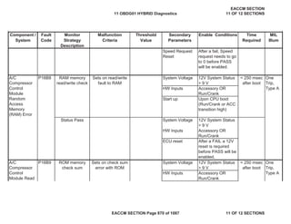
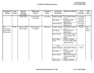
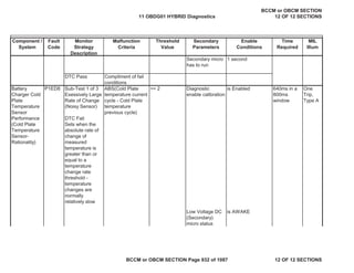
Internal
Control
Module Knock
Sensor
Processor 1
Performance
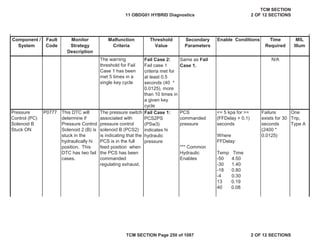
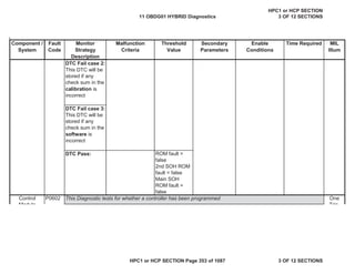
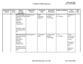
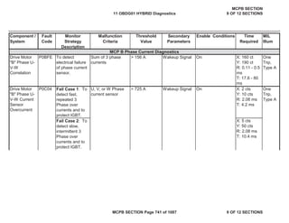
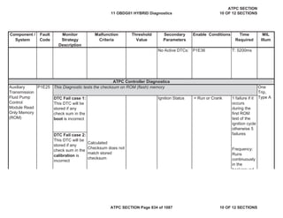
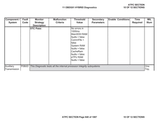
P06B6 This diagnostic
checks for a fault
with the internal
test circuit used
only for the '20
kHz' method of
the Open Circuit
Gated FFT
Diagnostic Output
(VaKNKD_k_OpenT
estCktIntFilter[0])
>
OpenTestThres
hLo
and
<
OpenTestThres
hHi
Diagnostic
Enabled?
Enabled First Order Lag
Filter with
Weight
Coefficient
Type: B
MIL:
YES
Trips:
2
Engine Air Flow • 40 mg/cylinder Weight
Vref3 >
Fuel Pump
Control
Module
(FPCM)
Requested
MIL
Illumination
P069E Monitors the
FPCM MIL
request line to
determine when
the FPCM has
detected a MIL
illuminating fault.
Fuel Pump Control
Module Emissions-
Related DTC set
Time since power-
up
> 3 seconds Continuous
5 Volt
Reference #4
Circuit
P06A3 Detects a
continuous or
intermittent short
on the 5 volt
reference circuit
#4
> 6.41 19/39counts or
0.1875 sec
continuous; 12.5
ms/count in
main processor
or the difference
between ECM
filtered Vref4 and
Vref4 >
11 OBDG01 HYBRID Diagnostics
ECM SECTION
1 OF 12 SECTIONS
ECM SECTION Page 135 of 1087 1 OF 12 SECTIONS](https://image.slidesharecdn.com/chevroletvolthybriddtc-230327065334-9b8d0d74/85/Chevrolet-Volt-Hybrid-DTC-135-320.jpg)


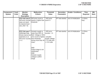


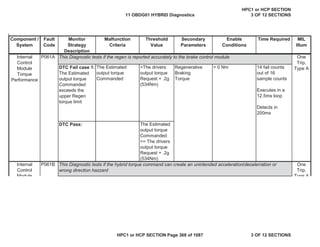
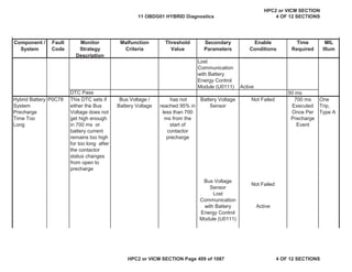
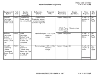
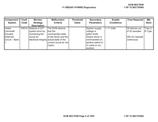
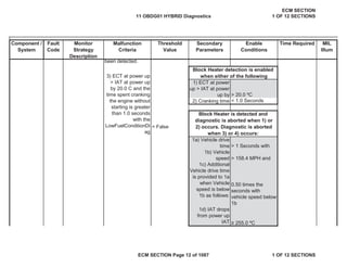
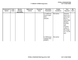
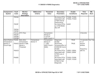
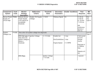
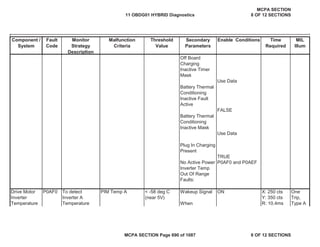
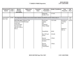
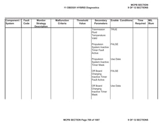
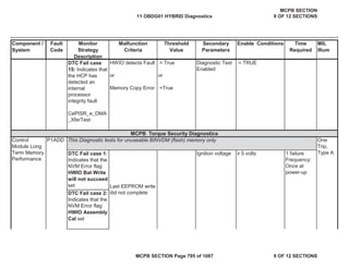
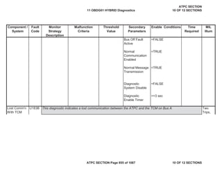
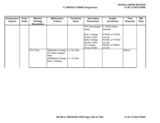
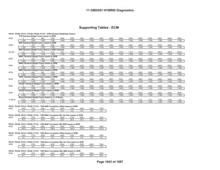
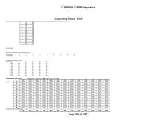
![MIL
Illum
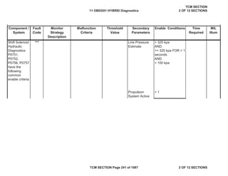
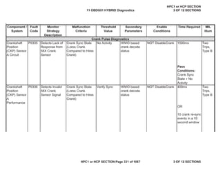
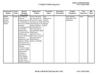
Component /
System
Fault
Code
Monitor
Strategy
Description
Malfunction
Criteria
Threshold
Value
Secondary
Parameters
Enable
Conditions
Time
Required
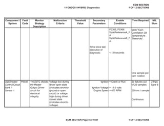
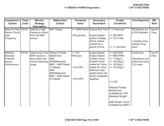
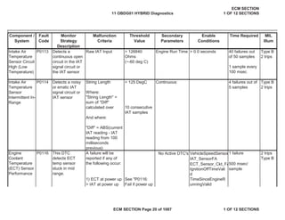
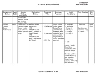
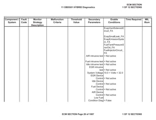
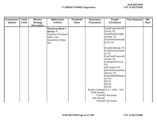
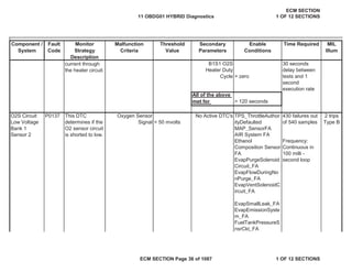
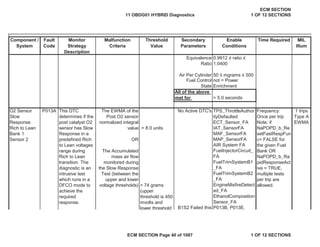
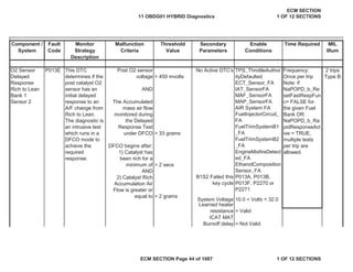
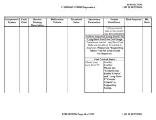
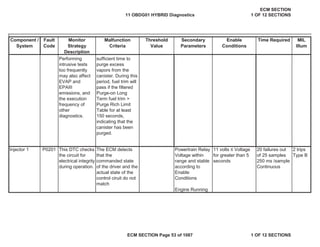
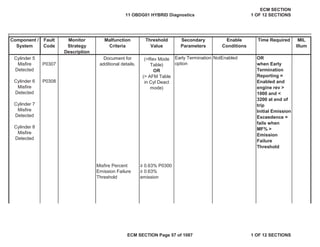
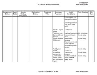
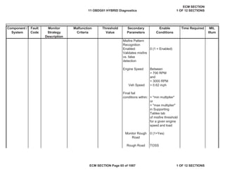
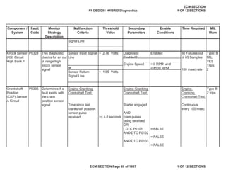
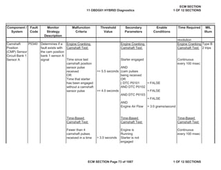
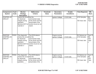
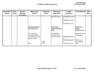
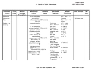
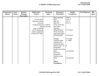
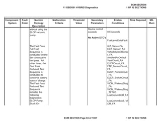
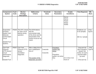
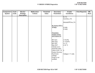
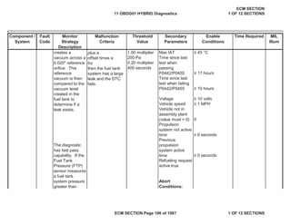
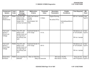
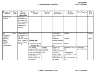
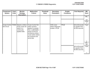
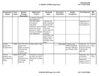
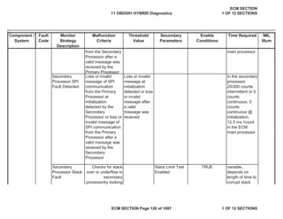
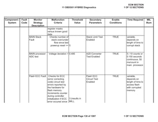
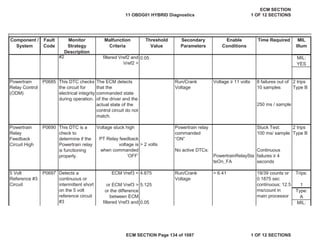
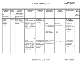
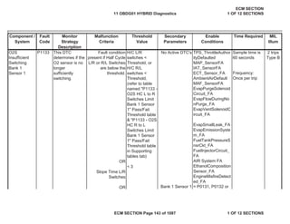
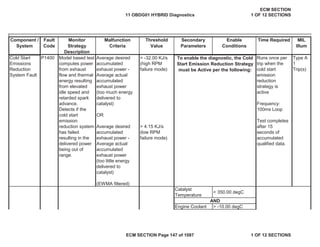
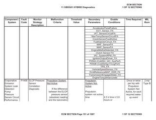
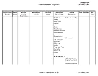
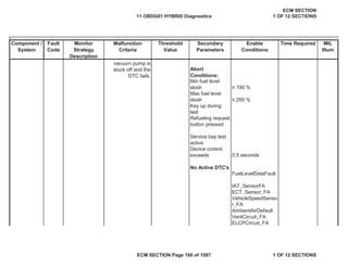
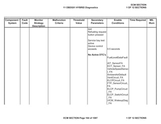
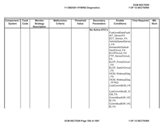
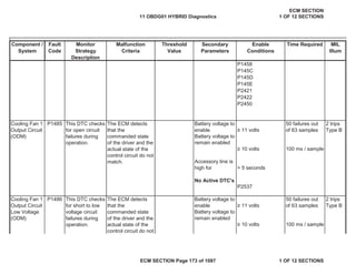
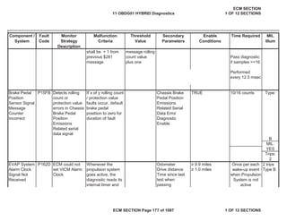
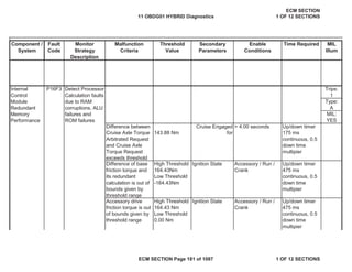
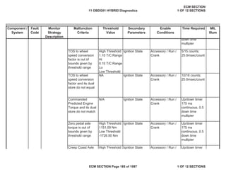
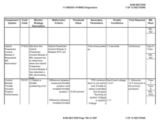
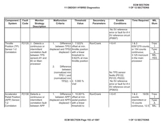
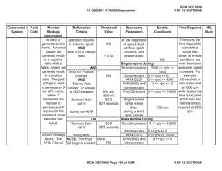
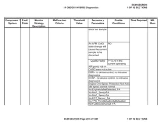
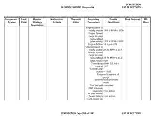
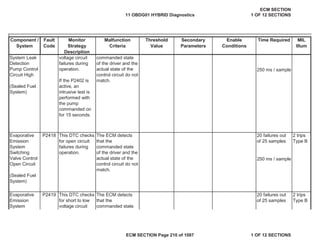
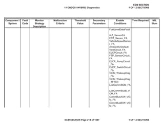
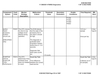
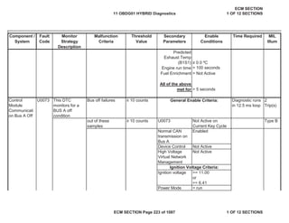
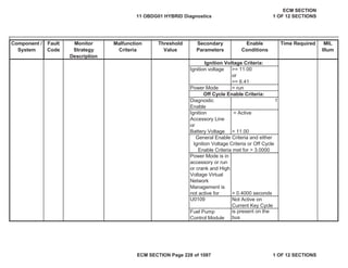
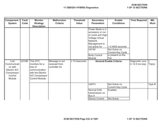
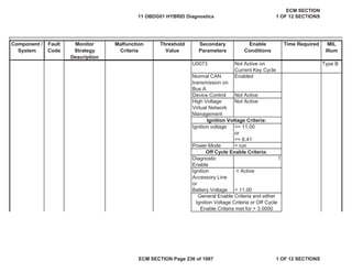
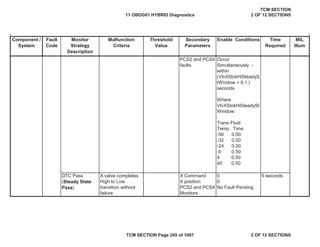
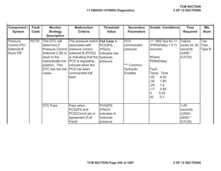
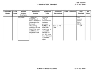
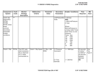
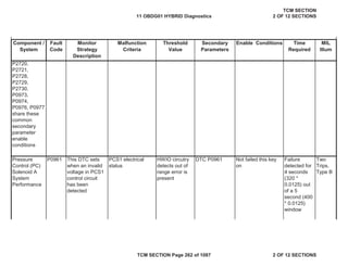
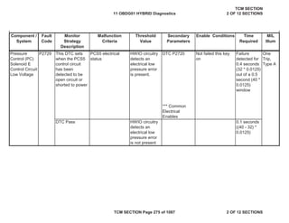
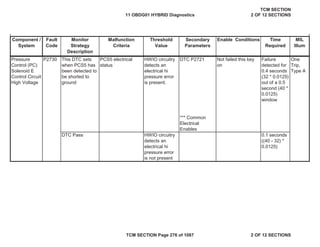
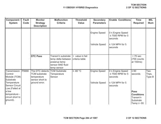
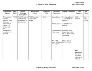
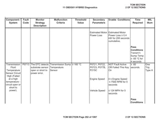
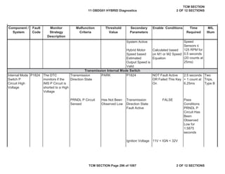
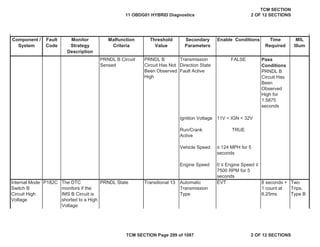
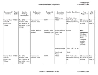
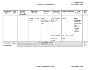
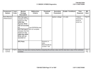
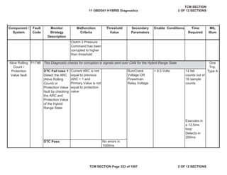
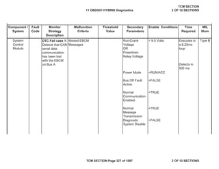
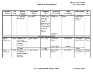
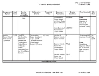
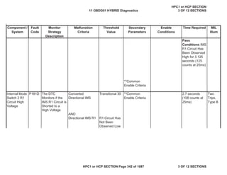
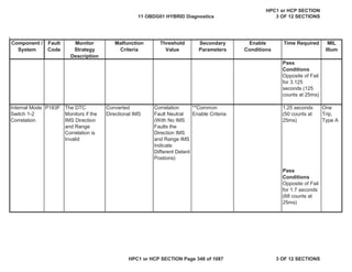
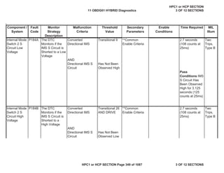
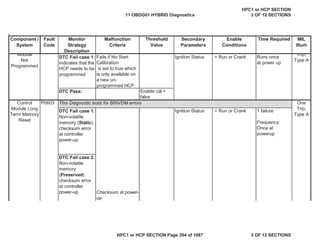
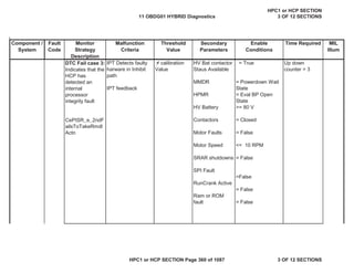
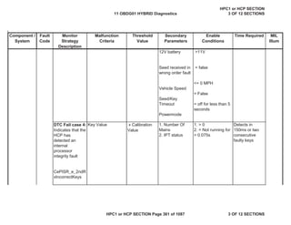
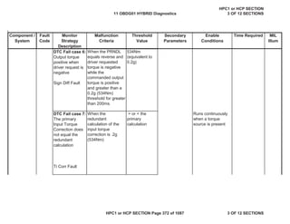
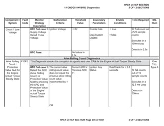
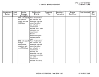
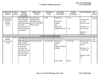
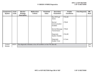
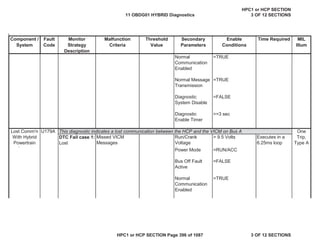
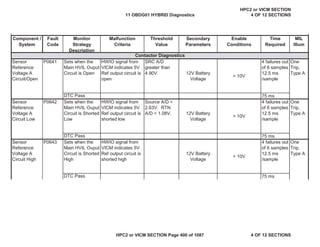
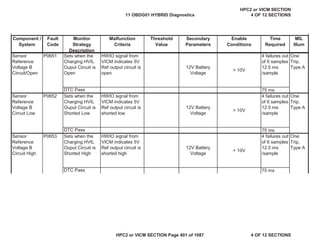
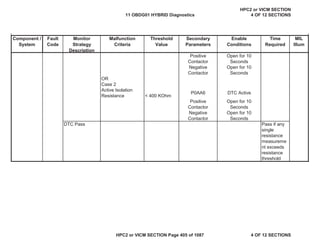
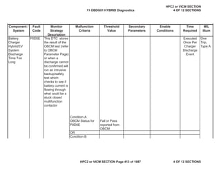
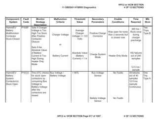
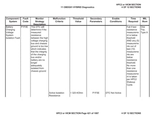
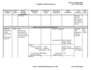
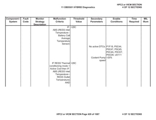
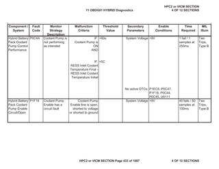
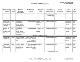
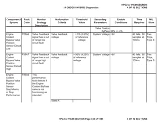
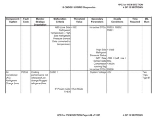
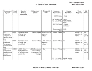
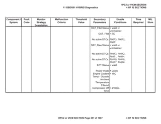
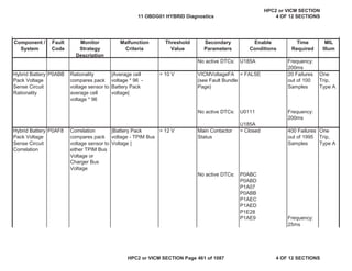
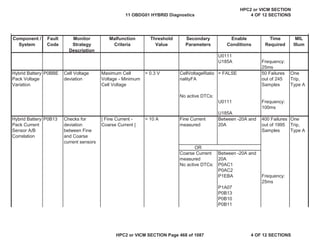
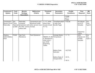
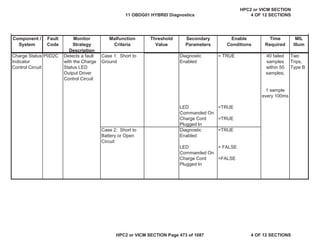
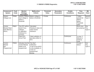
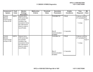
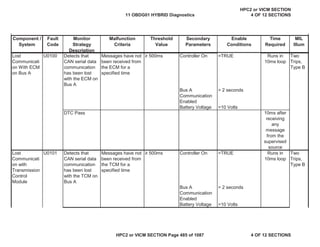
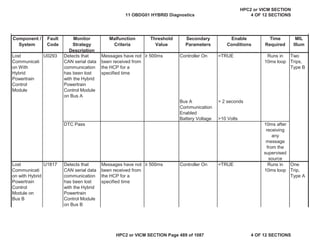
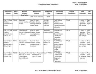
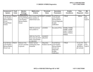
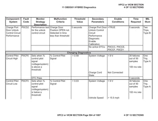
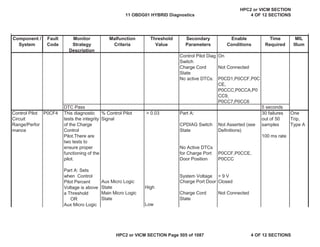
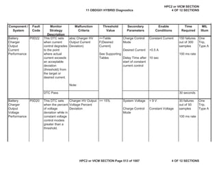
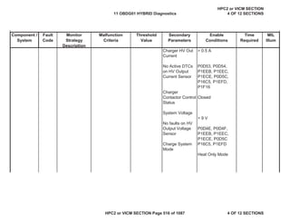
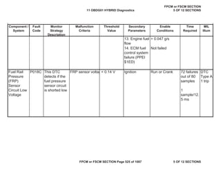
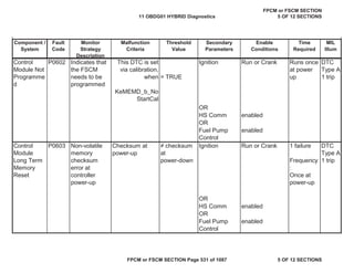
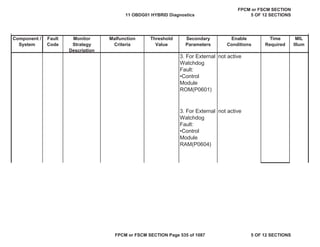
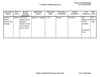
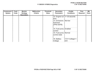
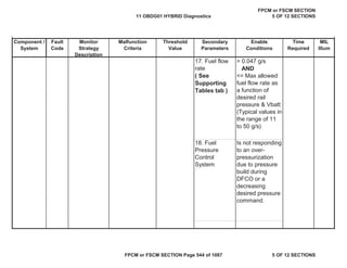
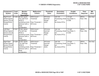
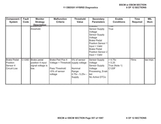
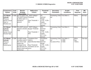
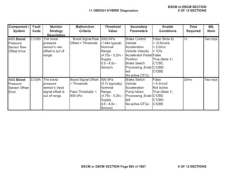
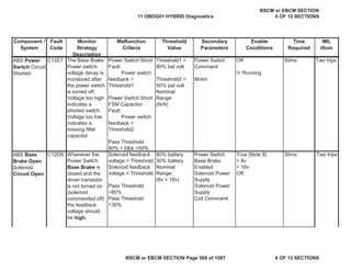
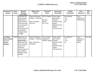
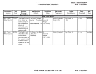
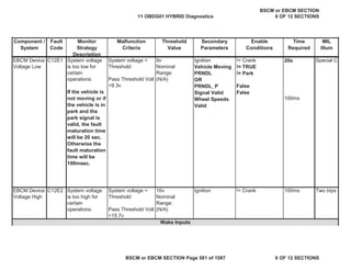
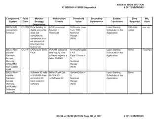
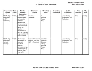
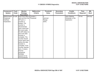
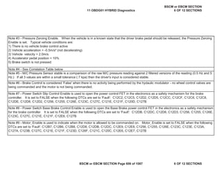
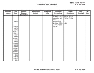
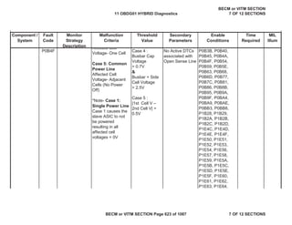
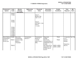
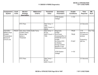
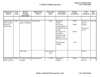
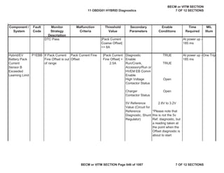
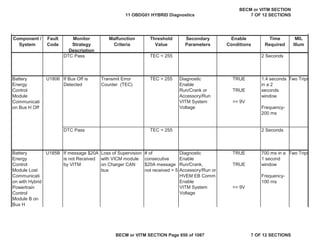
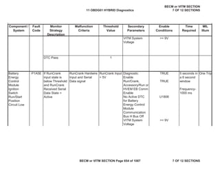
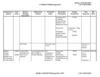
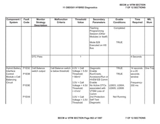
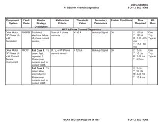
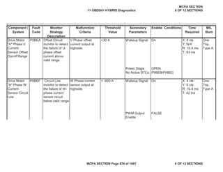
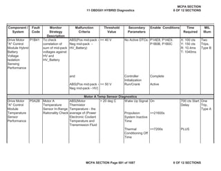
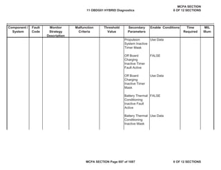
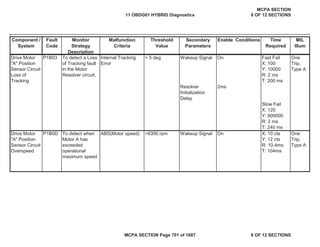
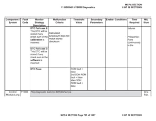
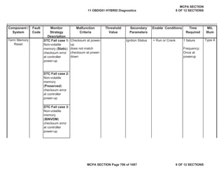
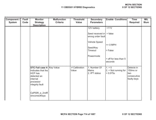
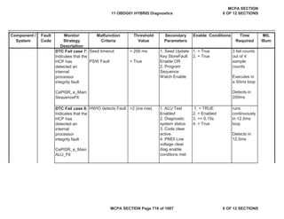
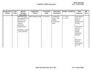
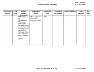
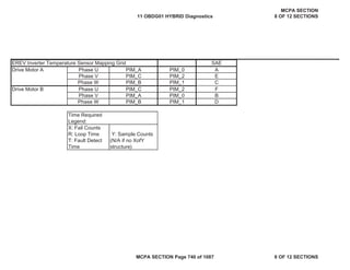
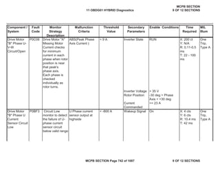
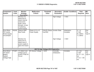
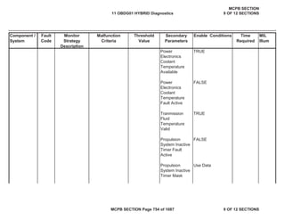
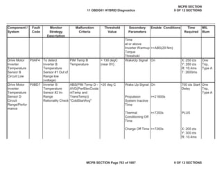
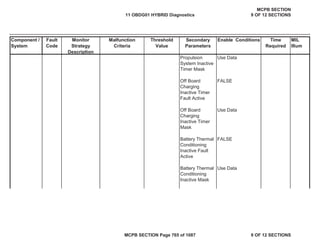
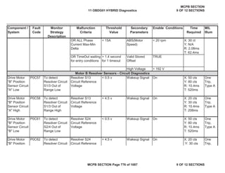
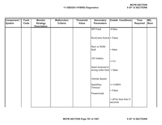
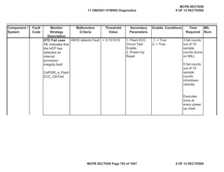
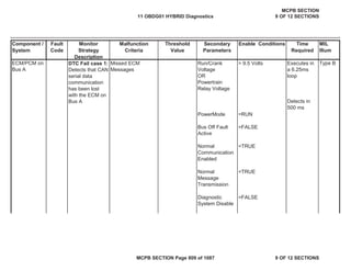
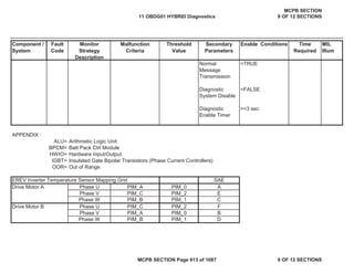
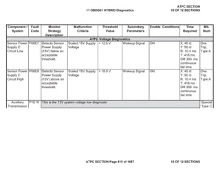
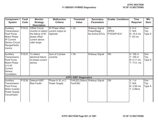
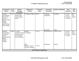
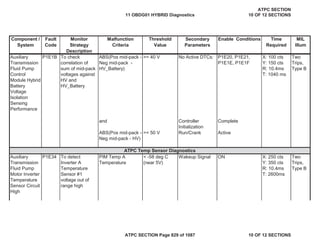
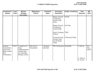
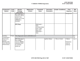
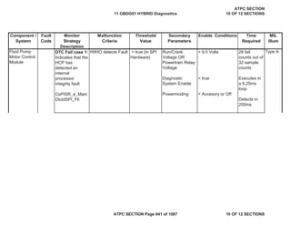
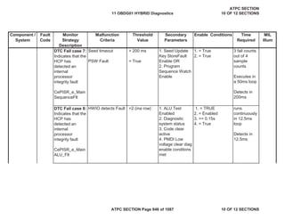
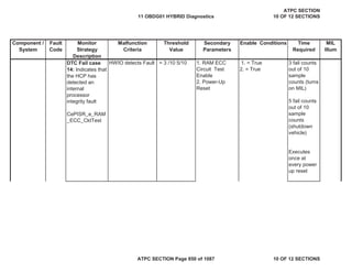
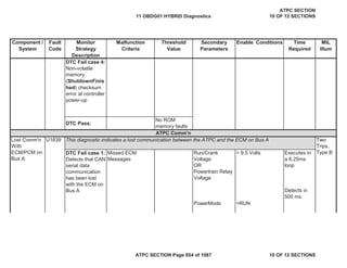
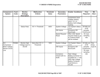
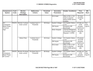
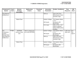
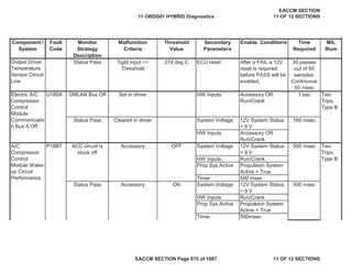
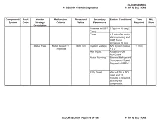
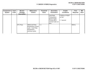
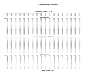
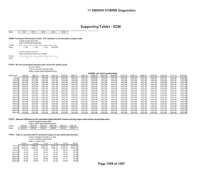
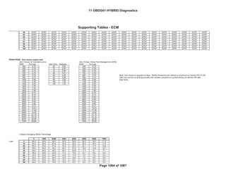
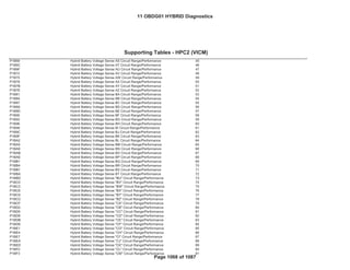
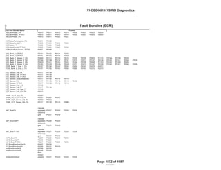
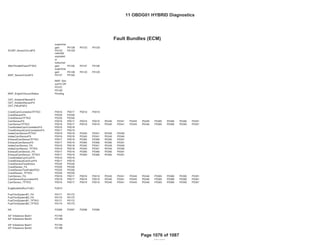
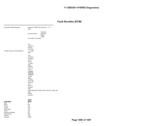
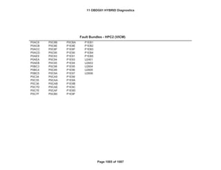
Proximity
Detection
Circuit Low
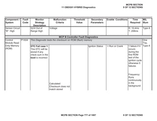
P0D58 Sets when
Proximity
Detection Circuit
Voltage is below
a threshold
Proximity Detection
Circuit Voltage
< 4.2 V. System Voltage
[Charge Port
Door
No Active DTCs
on Charge Port
Door Position
OR
Vehicle Speed
Shift Lever
Position
No Faults on
Vehicle Speed]
> 9V
Closed
P0CCF,P0CCE,
P0CCC
> 12.4 mph
Not in Park
30 failures
out of 50
samples
100 ms rate
One
Trip,
Type A
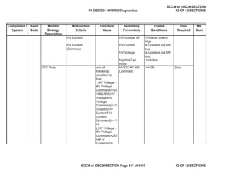
DTC Pass 5 seconds
11 OBDG01 HYBRID Diagnostics
HPC2 or VICM SECTION
4 OF 12 SECTIONS
HPC2 or VICM SECTION Page 508 of 1087 4 OF 12 SECTIONS](https://image.slidesharecdn.com/chevroletvolthybriddtc-230327065334-9b8d0d74/85/Chevrolet-Volt-Hybrid-DTC-508-320.jpg)
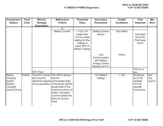
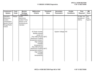
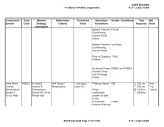
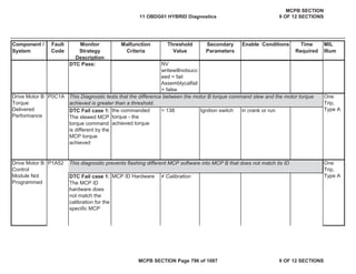
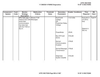
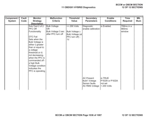
![MIL
Illum
Component /
System
Fault
Code
Monitor
Strategy
Description
Malfunction
Criteria
Threshold
Value
Secondary
Parameters
Enable
Conditions
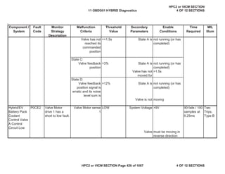
Time
Required
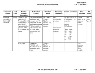
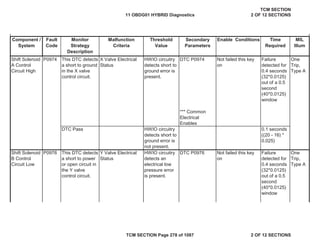
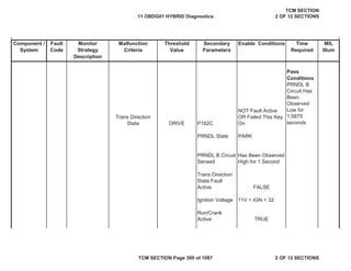
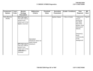
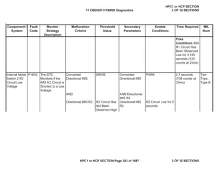
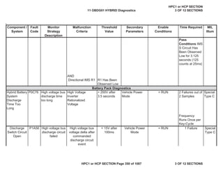
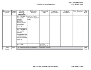
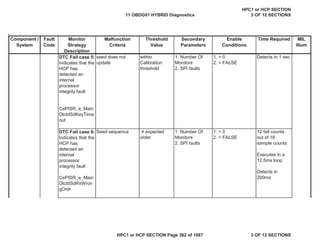
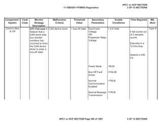
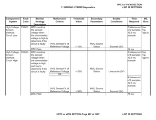
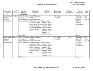
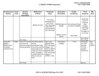
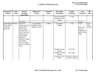
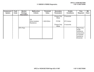
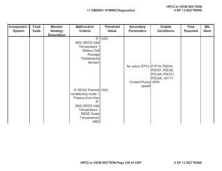
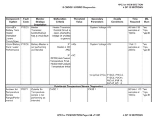
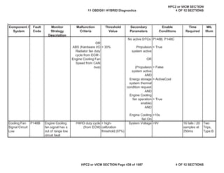
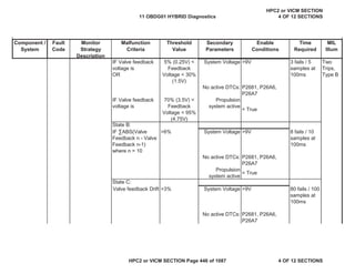
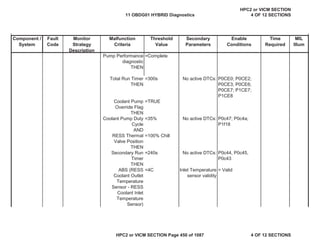
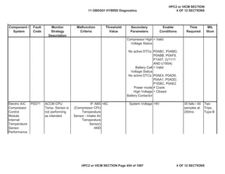
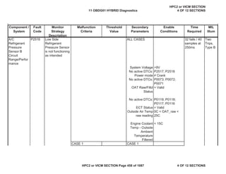
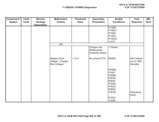
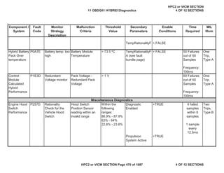
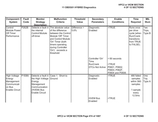
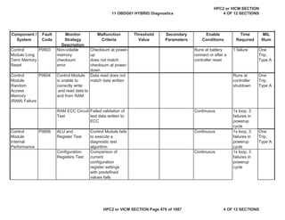
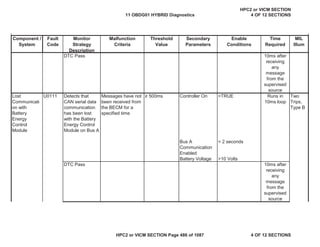
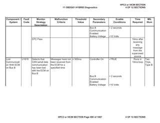
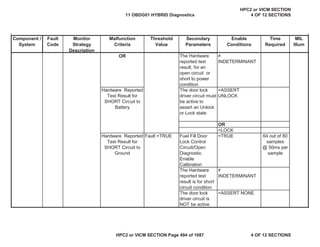
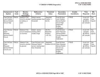
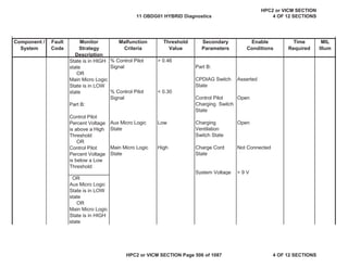
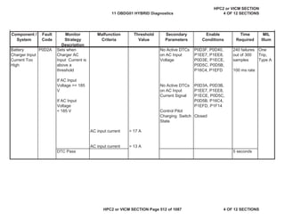
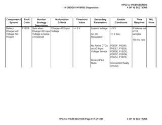
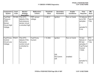
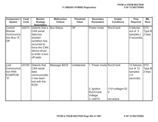
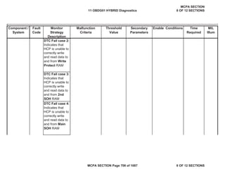
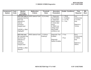
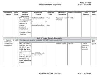
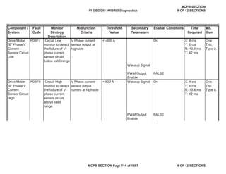
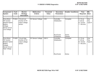
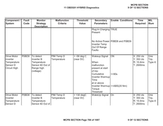
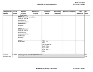
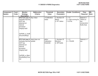
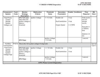
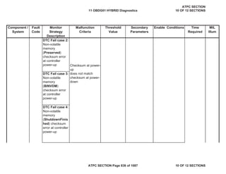
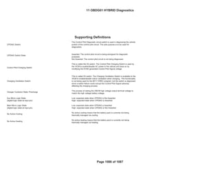
the bus voltage
must rise and be
within the
calculated
deadband
window for a
continuous time
of at least 0.25
seconds and
before 10
seconds has
elapsed since
the beginning of
precharge.
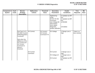
DTC Pass abs({[Charger Bus
Voltage / Battery
Pack Voltage] - 1}x
100)
AND
Precharge
Complete Window
Time
< 5%
>= 0.25
seconds
0.25 sec
11 OBDG01 HYBRID Diagnostics
HPC2 or VICM SECTION
4 OF 12 SECTIONS
HPC2 or VICM SECTION Page 510 of 1087 4 OF 12 SECTIONS](https://image.slidesharecdn.com/chevroletvolthybriddtc-230327065334-9b8d0d74/85/Chevrolet-Volt-Hybrid-DTC-510-320.jpg)
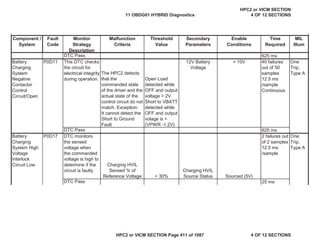
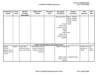
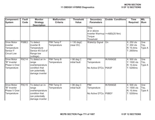
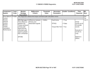
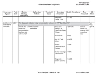
![MIL
Illum
Component /
System
Fault
Code
Monitor
Strategy
Description
Malfunction
Criteria
Threshold
Value
Secondary
Parameters
Enable
Conditions
Time
Required
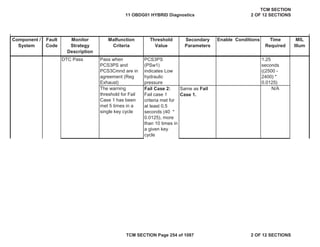
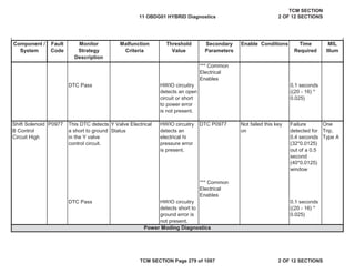
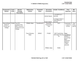
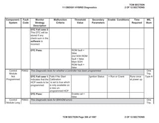
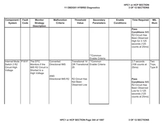
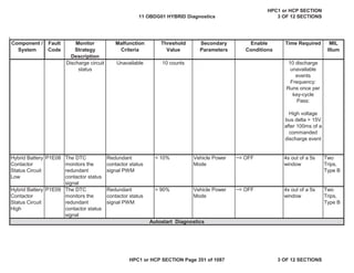
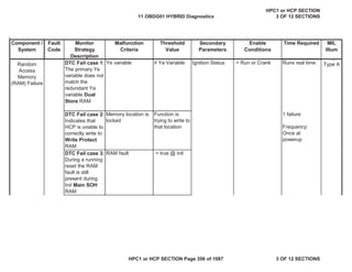
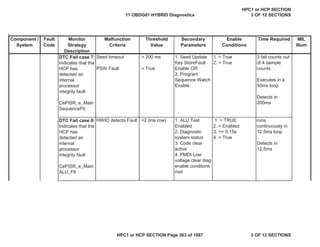
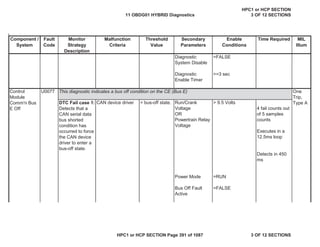
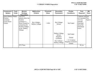
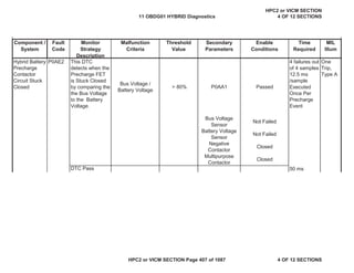
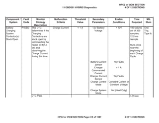
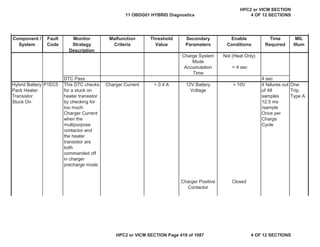
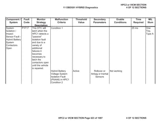
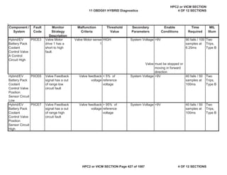
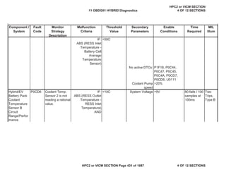
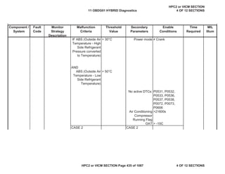
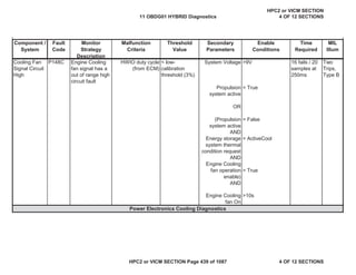
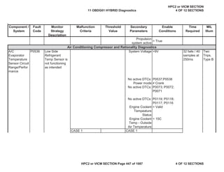
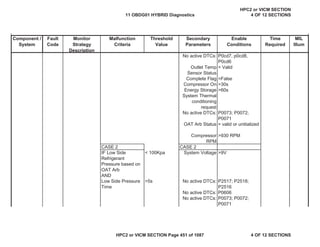
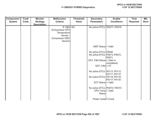
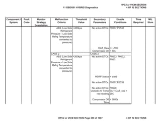
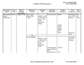
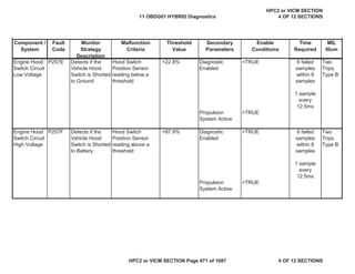
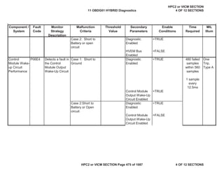
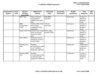
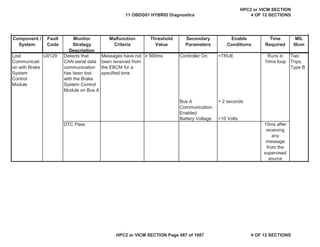
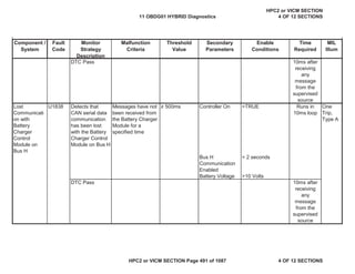
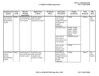
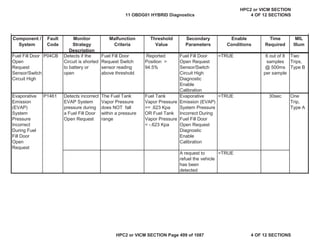
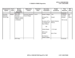
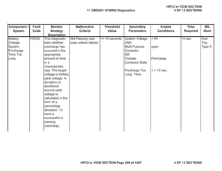
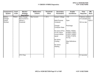
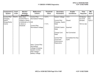
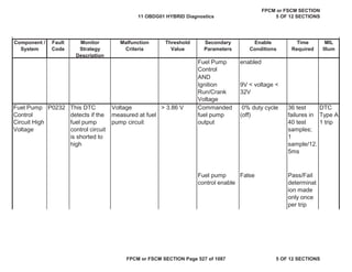
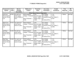
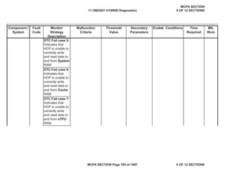
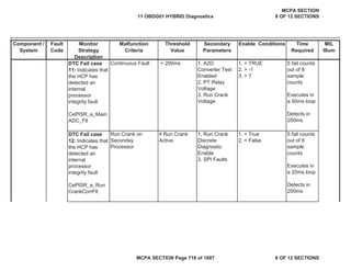
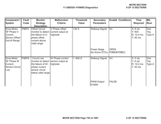
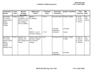
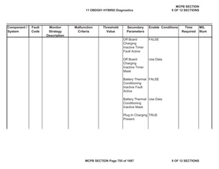
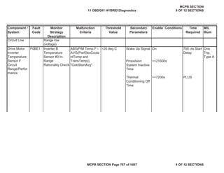
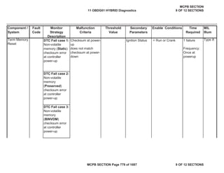
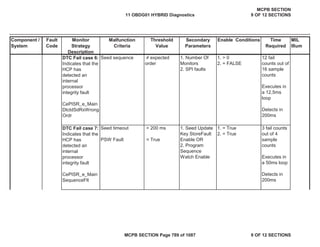
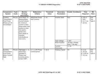
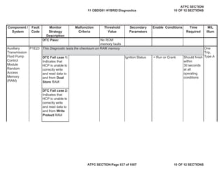
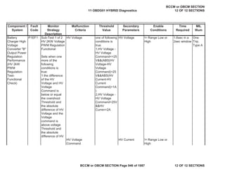
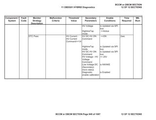
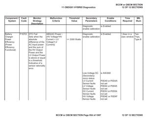
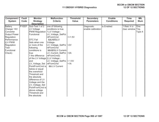
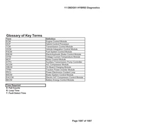
Battery
Charger
Output
Voltage Too
Low
P0D21 This DTC sets
when the Battery
Chargers output
voltage is too
low. It is
conducted in
distinct parts.
Part A: Not in
Charger Heat
Only Mode
Part B: In
Charger Heat
Only Mode
Bus Voltage
Actual Charger Bus
Voltage /Expected
Charger Bus
Voltage
Note: Expected
Charger Bus
Voltage = HV
Charger Current x
70 Ohms
< 150 V
< .75
Part A:
[Charge Control
Mode
or
Charge Control
Mode]
No Active DTCs
on HV Output
Voltage Sensor
Charge System
Mode
Part B:
Charge Control
Mode
Thermal
Condition
Request
Multi-Purpose
Contactor State
Constant Current
Constant Voltage
P0D4E, P0D4F,
P1EEB, P1EEC,
P1ECE, P0D5C
P16C5, P1EFD
Not in Heat Only
Mode
Constant Current
Active Heat
8 failures out
of 10
samples
100 ms rate
One
Trip,
Type A
11 OBDG01 HYBRID Diagnostics
HPC2 or VICM SECTION
4 OF 12 SECTIONS
HPC2 or VICM SECTION Page 515 of 1087 4 OF 12 SECTIONS](https://image.slidesharecdn.com/chevroletvolthybriddtc-230327065334-9b8d0d74/85/Chevrolet-Volt-Hybrid-DTC-515-320.jpg)


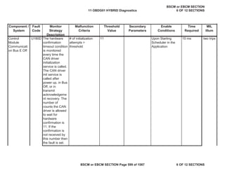


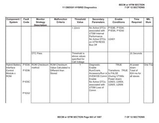


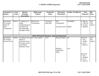
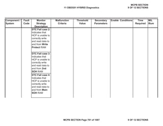


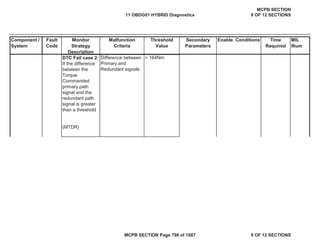


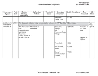

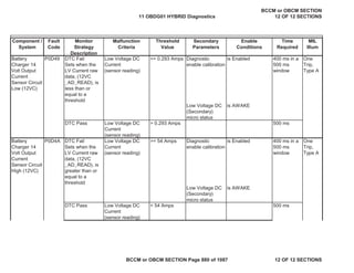
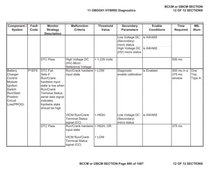
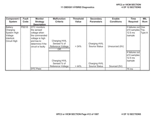
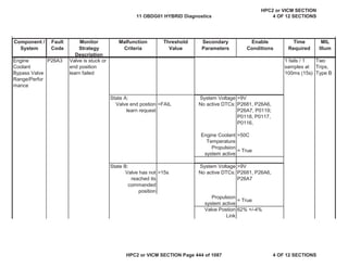
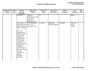
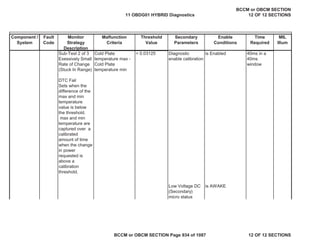
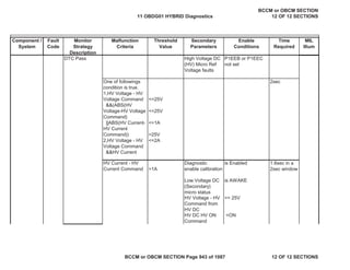
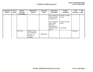
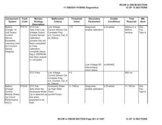
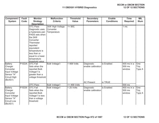
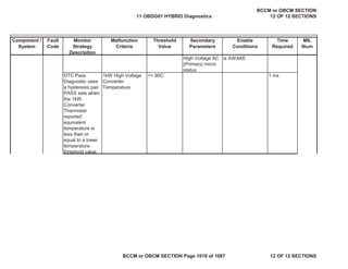
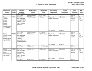
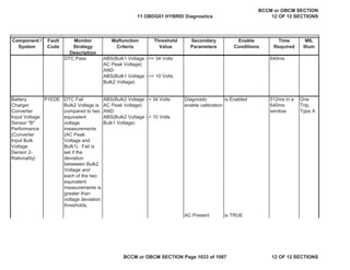
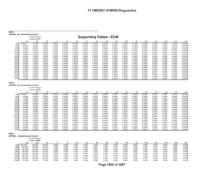
![Component /
System
Fault
Code
Monitor
Strategy
Description
Malfunction
Criteria
Threshold
Value
Secondary
Parameters
Enable
Conditions
Time
Required
MIL
Illum
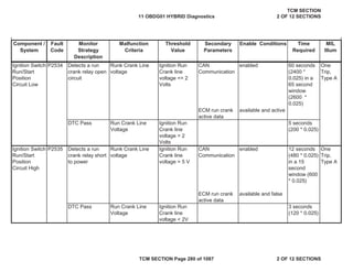
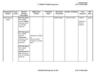
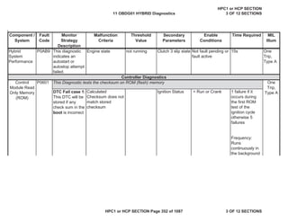
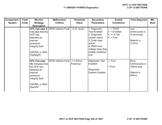
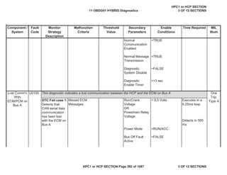
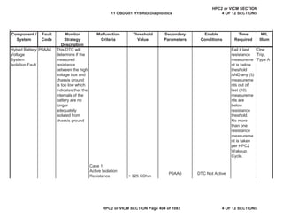
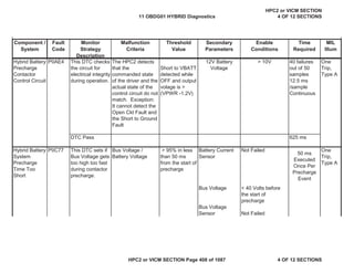
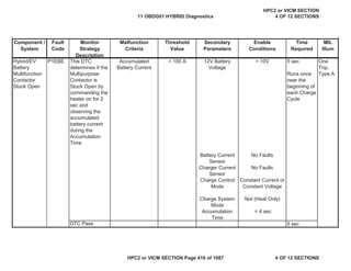
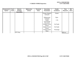
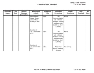
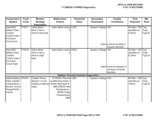
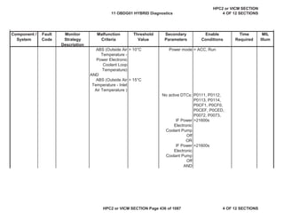
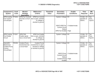
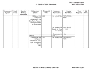
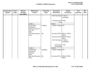
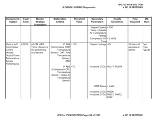
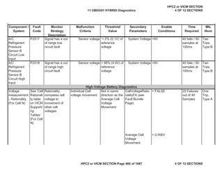
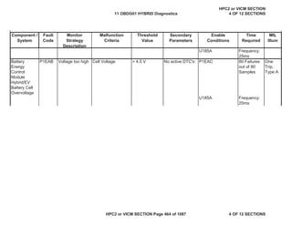
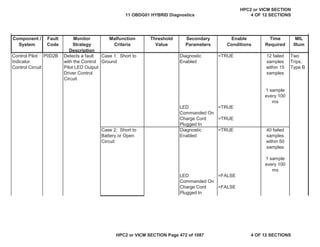
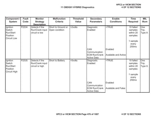
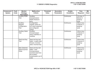
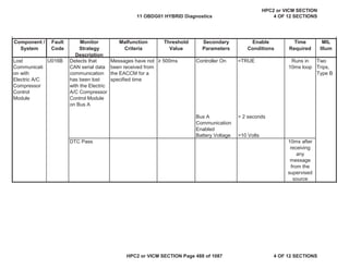
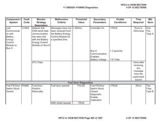
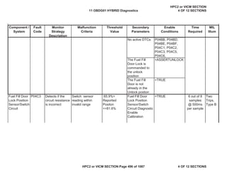
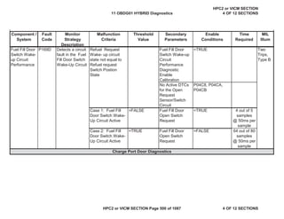
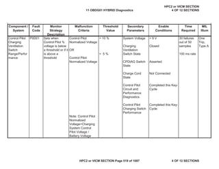
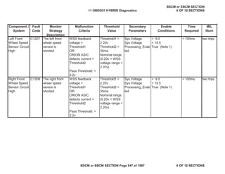
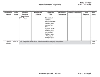
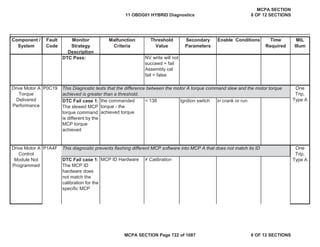
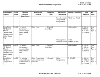
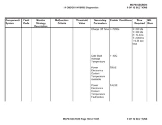
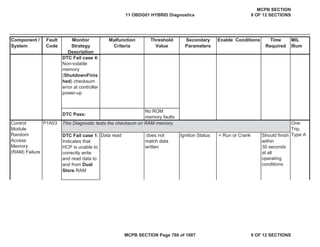
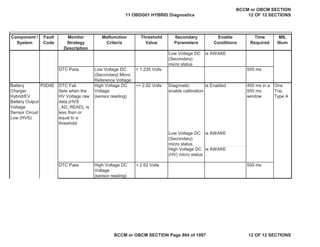
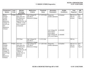
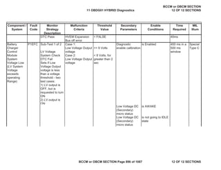
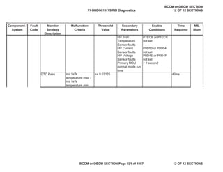
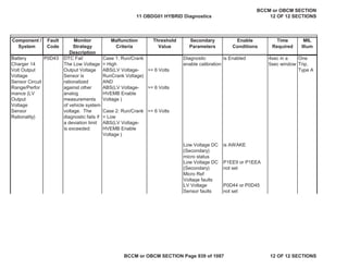
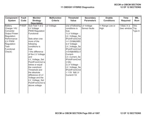
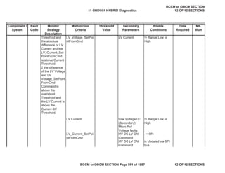
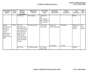
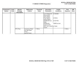
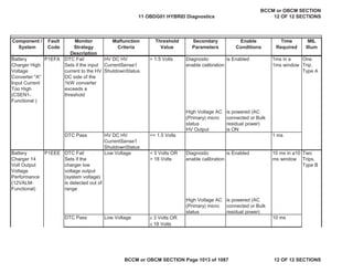
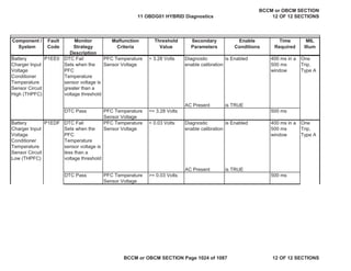
Battery
Charger
Control
Module Read
Only Memory
(ROM) Error
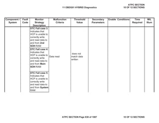
DTC Fail
Sets When
checksum
verification on
application/calibr
ation area fails
Checksum
verification fails
Diagnostic
enable calibration
is Enabled 20 ms in a
20 ms
window, only
execute at
end of
program
mode
One
Trip,
Type A
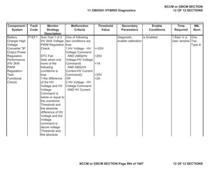
Low Voltage DC
(Secondary)
micro status
is AWAKE
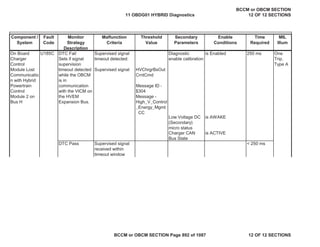
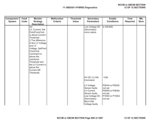
DTC Pass Checksum
verification passes
20ms
Battery
Charger
Control
Module SPI
Bus 1 (SPI
Communicatio
n Fault -
Primary)
Sub-Test 1 of 5
SPI Primary Mico
Message
Checksum Error
DTC Fail
Sets when any
Primary SPI
checksum error
count for a SPI
Message is
greater than or
equal to the
counter threshold
MessageChkSumEr
rCntr[AC Meas
Msg], OR
MessageChkSumEr
rCntr[OBD Msg],
OR
MessageChkSumEr
rCntr[Primary
Status], OR
MessageChkSumEr
rCntr[Temperature
Msg]
>= 2
>= 2
>= 2
>= 2
Diagnostic
enable calibration
is Enabled 44 ms in a
44 ms
window
One
Trip,
Type A
P16C1
P16C4
11 OBDG01 HYBRID Diagnostics
BCCM or OBCM SECTION
12 OF 12 SECTIONS
BCCM or OBCM SECTION Page 899 of 1087 12 OF 12 SECTIONS](https://image.slidesharecdn.com/chevroletvolthybriddtc-230327065334-9b8d0d74/85/Chevrolet-Volt-Hybrid-DTC-899-320.jpg)
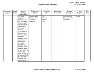
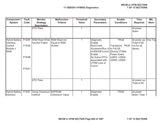
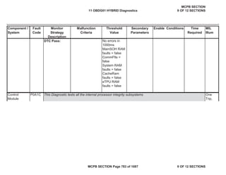
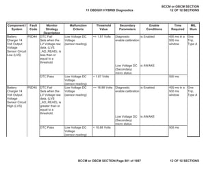
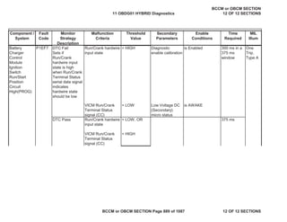
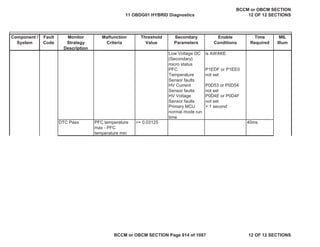
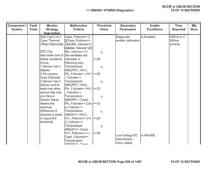
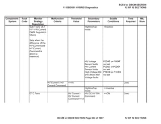
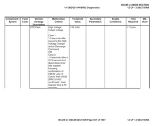
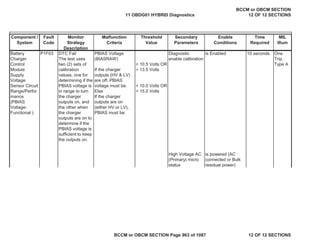
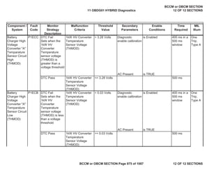
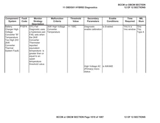
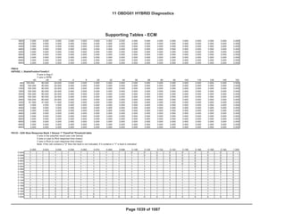
![Component /
System
Fault
Code
Monitor
Strategy
Description
Malfunction
Criteria
Threshold
Value
Secondary
Parameters
Enable
Conditions
Time
Required
MIL
Illum
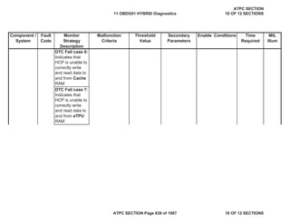
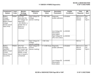
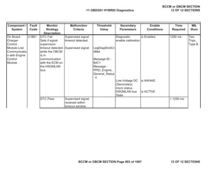
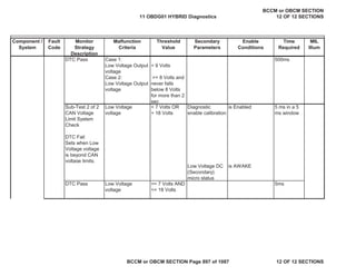
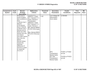
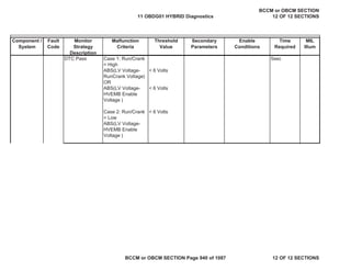
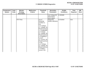
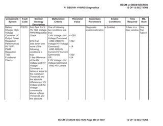
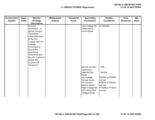
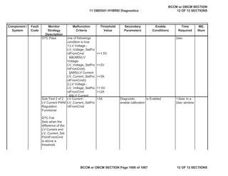
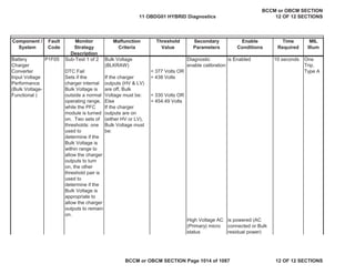
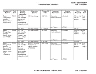
Low Voltage DC
(Secondary)
micro status
is AWAKE
SPI mode = NORMAL
DTC Pass MessageChkSumEr
rCntr[AC Meas
Msg], AND
MessageChkSumEr
rCntr[OBD Msg],
AND
MessageChkSumEr
rCntr[Primary
Status], AND
MessageChkSumEr
rCntr[Temperature
Msg]
< 2
< 2
< 2
< 2
22 ms
(message
trans rate)
Sub-Test 2 of 5
SPI Primary
Micro Message
Timeout Error
DTC Fail
Sets when any
Primary SPI
Message is not
received within
an expected time
window
MessageTimer[AC
Meas Msg], OR
MessageTimer[OB
D Msg], OR
MessageTimer[Prim
ary Status], OR
MessageTimer[Tem
perature Msg]
>= 65 ms
>= 65 ms
>= 65 ms
>= 65 ms
Diagnostic
enable calibration
is Enabled 65 ms
11 OBDG01 HYBRID Diagnostics
BCCM or OBCM SECTION
12 OF 12 SECTIONS
BCCM or OBCM SECTION Page 900 of 1087 12 OF 12 SECTIONS](https://image.slidesharecdn.com/chevroletvolthybriddtc-230327065334-9b8d0d74/85/Chevrolet-Volt-Hybrid-DTC-900-320.jpg)
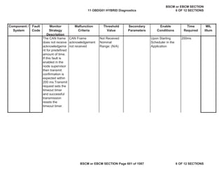
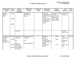
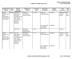
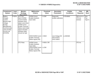
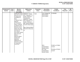
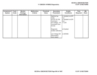
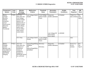
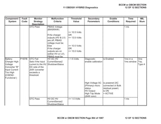
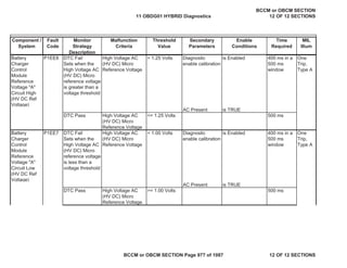
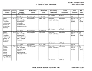
![Component /
System
Fault
Code
Monitor
Strategy
Description
Malfunction
Criteria
Threshold
Value
Secondary
Parameters
Enable
Conditions
Time
Required
MIL
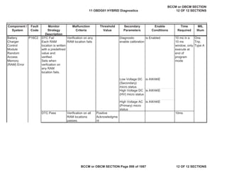
Illum
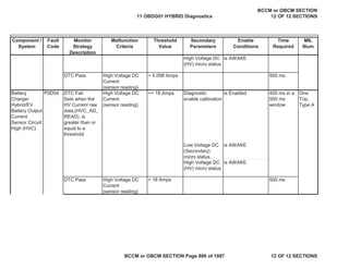
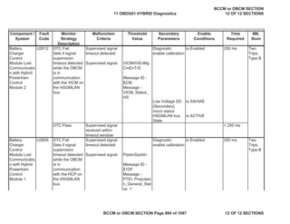
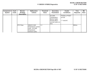
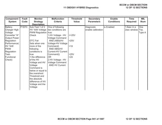
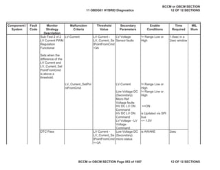
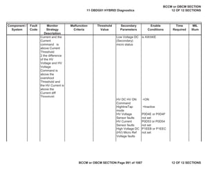
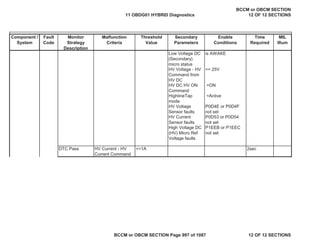
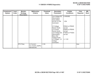
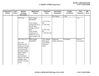
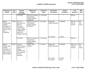
Low Voltage DC
(Secondary)
micro status
is AWAKE
SPI mode = NORMAL
DTC Pass MessageTimer[AC
Meas Msg], AND
MessageTimer[OB
D Msg], AND
MessageTimer[Prim
ary Status], AND
MessageTimer[Tem
perature Msg]
< 65 ms
< 65 ms
< 65 ms
< 65 ms
< 65 ms
Sub-Test 3 of 5
SPI Primary
Micro Node
Timeout Error
DTC Fail
Sets when
Primary SPI
Resynch Error
Counter is
greater than or
equal to the
counter threshold
SpiResynchErrorCo
unter[PRI]
>= 1 Diagnostic
enable calibration
is Enabled 3 - 5 ms
Low Voltage DC
(Secondary)
micro status
is AWAKE
11 OBDG01 HYBRID Diagnostics
BCCM or OBCM SECTION
12 OF 12 SECTIONS
BCCM or OBCM SECTION Page 901 of 1087 12 OF 12 SECTIONS](https://image.slidesharecdn.com/chevroletvolthybriddtc-230327065334-9b8d0d74/85/Chevrolet-Volt-Hybrid-DTC-901-320.jpg)
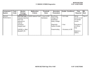
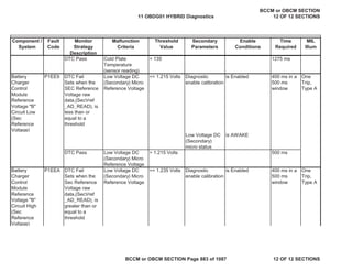
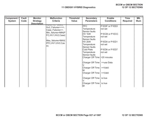
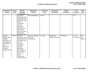
![Component /
System
Fault
Code
Monitor
Strategy
Description
Malfunction
Criteria
Threshold
Value
Secondary
Parameters
Enable
Conditions
Time
Required
MIL
Illum
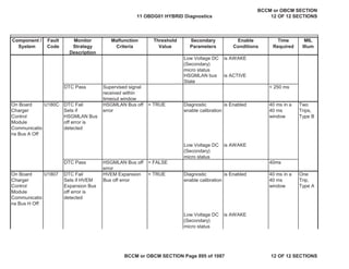
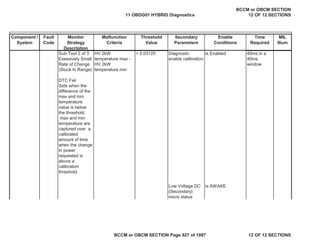
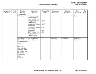
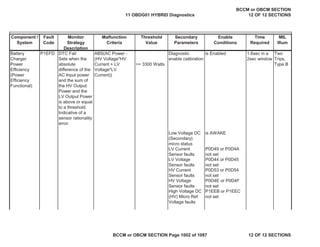
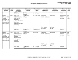
SPI mode = NORMAL OR
SYNCH
DTC Pass SpiResynchErrorCo
unter[PRI]
< 1 < 3 - 5 ms
(depends on
message
received)
Sub-Test 4 of 5
SPI Primary
Micro Channel
Rationality Error
DTC Fail
Sets when
Primary Channel
SPI Mode takes
longer than a
timer threshold to
reach Normal
Mode
SpiChannelRational
ityTimerInst[PRI]
>= 1000 ms Diagnostic
enable calibration
is Enabled 1000 ms
Low Voltage DC
(Secondary)
micro status
is AWAKE
SPI mode HV
channel
= NORMAL
SPI mode
Primary channel
= SYNCH OR
VERIFY
DTC Pass SpiChannelRational
ityTimerInst[PRI]
< 1000 ms < 1000 ms
11 OBDG01 HYBRID Diagnostics
BCCM or OBCM SECTION
12 OF 12 SECTIONS
BCCM or OBCM SECTION Page 902 of 1087 12 OF 12 SECTIONS](https://image.slidesharecdn.com/chevroletvolthybriddtc-230327065334-9b8d0d74/85/Chevrolet-Volt-Hybrid-DTC-902-320.jpg)
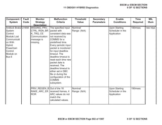
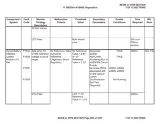
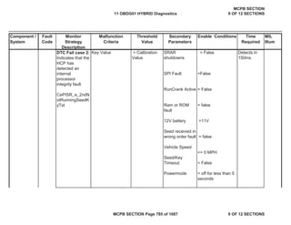
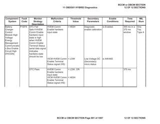
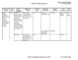
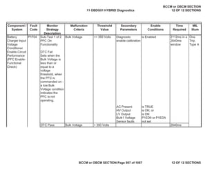
![Component /
System
Fault
Code
Monitor
Strategy
Description
Malfunction
Criteria
Threshold
Value
Secondary
Parameters
Enable
Conditions
Time
Required
MIL
Illum
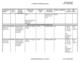
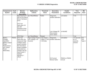
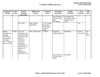
Sub-Test 5 of 5
SPI Primary
Micro Driver
Hardware Error
DTC Fail
Sets when
Primary SPI
hardware driver
errors received
spi_ResultStatus Failed Diagnostic
enable calibration
is Enabled 1 ms
Low Voltage DC
(Secondary)
micro status
is AWAKE
DTC Pass spi_ResultStatus Passed 1 ms
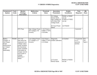
Battery
Charger
Control
Module SPI
Bus 1 (SPI
Communicatio
n Fault - HV
DC)
Sub-Test 1 of 5
SPI HV DC Micro
Message
Checksum Error
DTC Fail
Sets when any
HV DC SPI
checksum error
count for a SPI
Message is
greater than or
equal to the
counter threshold
MessageChkSumEr
rCntr[HV DC Meas
Msg]
>= 2 Diagnostic
enable calibration
is Enabled 44 ms in a
44 ms
window
One
Trip,
Type A
P16C5
11 OBDG01 HYBRID Diagnostics
BCCM or OBCM SECTION
12 OF 12 SECTIONS
BCCM or OBCM SECTION Page 903 of 1087 12 OF 12 SECTIONS](https://image.slidesharecdn.com/chevroletvolthybriddtc-230327065334-9b8d0d74/85/Chevrolet-Volt-Hybrid-DTC-903-320.jpg)
![Component /
System
Fault
Code
Monitor
Strategy
Description
Malfunction
Criteria
Threshold
Value
Secondary
Parameters
Enable
Conditions
Time
Required
MIL
Illum
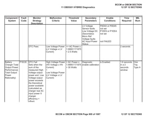
Low Voltage DC
(Secondary)
micro status
is AWAKE
SPI mode = NORMAL
DTC Pass MessageChkSumEr
rCntr[HV DC Meas
Msg]
< 2 22 ms
(message
trans rate)
Sub-Test 2 of 5
SPI HV DC Micro
Message
Timeout Error
DTC Fail
Sets when any
HV DC SPI
Message is not
received within
an expected time
window
MessageTimer[HV
DC Meas]
>= 65 ms Diagnostic
enable calibration
is Enabled 65 ms
Low Voltage DC
(Secondary)
micro status
is AWAKE
SPI mode = NORMAL
DTC Pass MessageTimer[HV
DC Meas]
< 65 ms < 65 ms
11 OBDG01 HYBRID Diagnostics
BCCM or OBCM SECTION
12 OF 12 SECTIONS
BCCM or OBCM SECTION Page 904 of 1087 12 OF 12 SECTIONS](https://image.slidesharecdn.com/chevroletvolthybriddtc-230327065334-9b8d0d74/85/Chevrolet-Volt-Hybrid-DTC-904-320.jpg)
![Component /
System
Fault
Code
Monitor
Strategy
Description
Malfunction
Criteria
Threshold
Value
Secondary
Parameters
Enable
Conditions
Time
Required
MIL
Illum
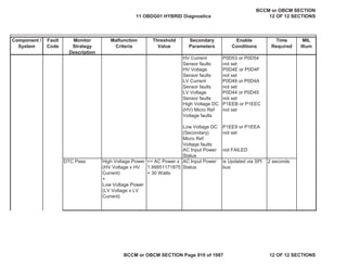
Sub-Test 3 of 5
SPI HV DC Micro
Node Timeout
Error
DTC Fail
Sets when HV
DC SPI Resynch
Error Counter is
greater than or
equal to the
counter threshold
SpiResynchErrorCo
unter[PRI]
>= 1 Diagnostic
enable calibration
is Enabled 3 - 5 ms
SPI mode = NORMAL OR
SYNCH
Low Voltage DC
(Secondary)
micro status
is AWAKE
DTC Pass SpiResynchErrorCo
unter[PRI]
< 1 < 3 - 5 ms
(depends on
message
received)
11 OBDG01 HYBRID Diagnostics
BCCM or OBCM SECTION
12 OF 12 SECTIONS
BCCM or OBCM SECTION Page 905 of 1087 12 OF 12 SECTIONS](https://image.slidesharecdn.com/chevroletvolthybriddtc-230327065334-9b8d0d74/85/Chevrolet-Volt-Hybrid-DTC-905-320.jpg)
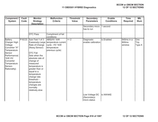
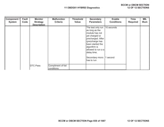
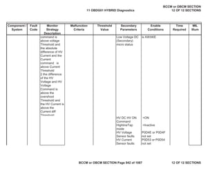
![Component /
System
Fault
Code
Monitor
Strategy
Description
Malfunction
Criteria
Threshold
Value
Secondary
Parameters
Enable
Conditions
Time
Required
MIL
Illum
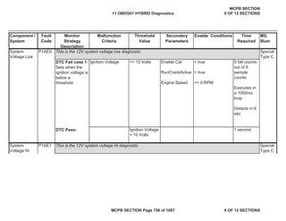
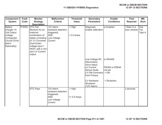
Sub-Test 4 of 5
SPI HV DC Micro
Channel
Rationality Error
DTC Fail
Sets when HV
DC Channel SPI
Mode takes
longer than a
timer threshold to
reach Normal
Mode
SpiChannelRational
ityTimerInst[PRI]
>= 1000 ms Diagnostic
enable calibration
is Enabled 1000 ms
Low Voltage DC
(Secondary)
micro status
is AWAKE
SPI mode
Primary channel
= NORMAL
SPI mode HV
channel
= SYNCH OR
VERIFY
DTC Pass SpiChannelRational
ityTimerInst[PRI]
< 1000 ms < 1000 ms
11 OBDG01 HYBRID Diagnostics
BCCM or OBCM SECTION
12 OF 12 SECTIONS
BCCM or OBCM SECTION Page 906 of 1087 12 OF 12 SECTIONS](https://image.slidesharecdn.com/chevroletvolthybriddtc-230327065334-9b8d0d74/85/Chevrolet-Volt-Hybrid-DTC-906-320.jpg)


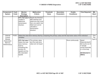
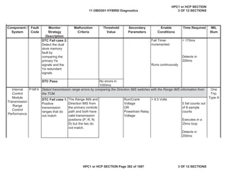
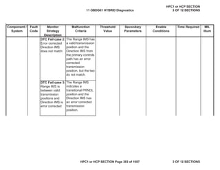
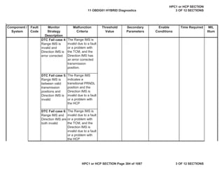
The document describes various OBD monitors and their strategies. It indicates that red OBD controllers are master ECMs that store codes and control the MIL, blue are primary controllers that also store codes, and orange are secondary controllers. It then provides details on numerous component monitors, including camshaft position monitors, oxygen sensor heater monitors, and temperature sensor monitors.