Download as PDF, PPTX


![Component/
System
Fault
Code
Monitor Strategy
Description
Malfunction Criteria Threshold Value Secondary Parameters Enable Conditions Time Required MIL
Illum.
Difference (absolute
value) in measured
pressure between BARO
sensor and TCIAP sensor
AND
Difference (absolute
value) in measured
pressure between BARO
sensor and MAP sensor
AND
Difference (absolute
value) in measured
pressure between TCIAP
sensor and MAP sensor
>
P0106, P2227, P227B,
P00C7: Maximum
pressure difference
[kPa]
AND
>
P0106, P2227, P227B,
P00C7: Maximum
pressure difference
[kPa]
AND
>
P0106, P2227, P227B,
P00C7: Maximum
pressure difference
[kPa]
Correlation diagnostic
enabled by calibration
Engine is running
Run Crankrelay supply
voltage in range
Engine speed
Requested fuel
Throttle measured
position
Engine Coolant
Temperature
No faults are present
== 1.00
> [V]
11.00
< [rpm]
1,100.00
< [mm^3]
20.00
> [%]
90.00
> [°C]
60.00
CrankSensor_FA
==FALSE
FUL_GenericInjSysFA
==FALSE
TPS_PstnSnsrFA
==FALSE
MAP_SensorCircuitFA
==FALSE
AAP2_SnsrCktFA
==FALSE
AAP_AAP5_SnsrCktFA
==FALSE
AAP_AAP2_SnsrStabFA
==FALSE
AAP_AAP5_SnsrStabFA
==FALSE
ECT_Sensor_FA
320.00
fail counters over
400.00
sample counters
sampling time is
12.5 ms
Multiple
Pressure
Sensor
Correlation
Performance
(US Market -
3 pressure
sensor
configuration
)
P00C7 This monitor is used to
identify if BARO, MAP
and TCIAP pressure
values are irrational
when compared to
each other.
The plausibility monitor
compares the BARO,
MAP and TCIAP
pressures in two
different conditions:
- at idle (part of the test
enabled when the
engine is running)
- between key off and
when the engine starts
running (part of the test
enabled when the
engine is not running).
If the three sensors are
not in agreement the
monitor is not able to
pinpoint the sensor(s)
that is/are not working
correctly and therefore
indicates that there is a
fault that impacts the
three sensors.
Type A,
1 Trips
18 OBDG04 ECM Summary Tables
ECM Section Page 22 of 1090 Page 22 of 1863
https://www.automotive-manuals.net/](https://image.slidesharecdn.com/gmcenginefaultcodesdtc1-230327071418-56d3c5bb/75/18-OBDG04-ECM-Summary-Tables-22-2048.jpg)
![Component/
System
Fault
Code
Monitor Strategy
Description
Malfunction Criteria Threshold Value Secondary Parameters Enable Conditions Time Required MIL
Illum.
==FALSE
MAF_MAF_SnsrFA
==FALSE
Difference (absolute
value) in measured
pressure between MAP
sensor and BARO sensor
AND
Difference (absolute
value) in measured
pressure between TCIAP
sensor and MAP sensor
AND
Difference (absolute
value) in measured
pressure between TCIAP
sensor and BARO sensor
OR
Difference (absolute
value) in measured
pressure between MAP
sensor and BARO sensor
AND
Difference (absolute
value) in measured
pressure between TCIAP
sensor and MAP sensor
AND
Difference (absolute
value) in measured
pressure between TCIAP
sensor and BARO sensor
OR
Difference (absolute
value) in measured
pressure between MAP
sensor and BARO sensor
> [kPa]
20.0
<= [kPa]
20.0
<= [kPa]
20.0
<= [kPa]
20.0
> [kPa]
20.0
<= [kPa]
20.0
<= [kPa]
20.0
Time between current
ignition cycle and the last
time the engine was
running
Engine is not rotating
Manifold Pressure
Manifold Pressure
Baro Pressure
Baro Pressure
TCIAP Pressure
TCIAP Pressure
No Active DTCs:
No Pending DTCs:
> [s]
5.0
>= [kPa]
50.0
<= [kPa]
115.0
>= [kPa]
50.0
<= [kPa]
115.0
>= [kPa]
50.0
<= [kPa]
115.0
EngineModeNotRunTimer
Error
MAP_SensorFA
AAP_SnsrFA
AAP2_SnsrFA
MAP_SensorCircuitFP
AAP_SnsrCktFP
AAP2_SnsrCktFP
fail counters
4
over sample
5
counters
sampling time is
12.5 ms
18 OBDG04 ECM Summary Tables
ECM Section Page 23 of 1090 Page 23 of 1863
https://www.automotive-manuals.net/](https://image.slidesharecdn.com/gmcenginefaultcodesdtc1-230327071418-56d3c5bb/75/18-OBDG04-ECM-Summary-Tables-23-2048.jpg)
![Component/
System
Fault
Code
Monitor Strategy
Description
Malfunction Criteria Threshold Value Secondary Parameters Enable Conditions Time Required MIL
Illum.
AND
Difference (absolute
value) in measured
pressure between TCIAP
sensor and MAP sensor
AND
Difference (absolute
value) in measured
pressure between TCIAP
sensor and BARO sensor
OR
Difference (absolute
value) in measured
pressure between MAP
sensor and BARO sensor
AND
Difference (absolute
value) in measured
pressure between TCIAP
sensor and MAP sensor
AND
Difference (absolute
value) in measured
pressure between TCIAP
sensor and BARO sensor
<= [kPa]
20.0
> [kPa]
20.0
> [kPa]
20.0
> [kPa]
20.0
> [kPa]
20.0
18 OBDG04 ECM Summary Tables
ECM Section Page 24 of 1090 Page 24 of 1863
https://www.automotive-manuals.net/](https://image.slidesharecdn.com/gmcenginefaultcodesdtc1-230327071418-56d3c5bb/75/18-OBDG04-ECM-Summary-Tables-24-2048.jpg)


![Component/
System
Fault
Code
Monitor Strategy
Description
Malfunction Criteria Threshold Value Secondary Parameters Enable Conditions Time Required MIL
Illum.
Difference (absolute
value) in measured
pressure between MAP
sensor and TCIAP sensor
AND
Difference (absolute
value) in measured
pressure between MAP
sensor and BARO sensor
AND
Difference (absolute
value) in measured
pressure between BARO
sensor and TCIAP sensor
>
P0106, P2227, P227B,
P00C7: Maximum
pressure difference
[kPa]
>
P0106, P2227, P227B,
P00C7: Maximum
pressure difference
[kPa]
<
P0106, P2227, P227B,
P00C7: Maximum
pressure difference
[kPa]
Correlation diagnostic
enabled by calibration
Engine is running
Run Crankrelay supply
voltage in range
Engine speed
Requested fuel
Throttle measured
position
Engine Coolant
Temperature
No faults are present
== 1.00
> [V]
11.00
< [rpm]
1,100.00
< [mm^3]
20.00
> [%]
90.00
> [°C]
60.00
CrankSensor_FA
==FALSE
FUL_GenericInjSysFA
==FALSE
TPS_PstnSnsrFA
==FALSE
MAP_SensorCircuitFA
==FALSE
AAP2_SnsrCktFA
==FALSE
AAP_AAP5_SnsrCktFA
==FALSE
AAP_AAP2_SnsrStabFA
==FALSE
AAP_AAP5_SnsrStabFA
==FALSE
ECT_Sensor_FA
320.00
fail counters over
400.00
sample counters
sampling time is
12.5 ms
Manifold
Absolute
Pressure
(MAP)
Sensor
Performance
(US Market -
3 pressure
sensor
configuration
)
P0106 This monitor is used to
identify MAP sensor
internal faults
(measurement with an
offset or a drift).
The plausibility monitor
compares the BARO,
MAP and TCIAP
pressures in two
different conditions:
- at idle (part of the test
enabled when the
engine is running)
- between key off and
when the engine starts
running (part of the test
enabled when the
engine is not running).
If MAP sensor is not in
agreement with the
other two the monitor is
able to pinpoint MAP
as the faulty sensor.
Type A,
1 Trips
18 OBDG04 ECM Summary Tables
ECM Section Page 33 of 1090 Page 33 of 1863
https://www.automotive-manuals.net/](https://image.slidesharecdn.com/gmcenginefaultcodesdtc1-230327071418-56d3c5bb/75/18-OBDG04-ECM-Summary-Tables-33-2048.jpg)
![Component/
System
Fault
Code
Monitor Strategy
Description
Malfunction Criteria Threshold Value Secondary Parameters Enable Conditions Time Required MIL
Illum.
==FALSE
MAF_MAF_SnsrFA
==FALSE
MAP sensor
OR
MAP sensor
< [kPa]
50.0
> [kPa]
115.0
Time between current
ignition cycle and the last
time the engine was
running
Engine is not rotating
No Active DTCs:
No Pending DTCs:
> [s]
5.0
EngineModeNotRunTimer
Error
MAP_SensorCircuitFA
AAP_SnsrCktFA
MAP_SensorCircuitFP
AAP_SnsrCktFP
fail counters
4
over sample
5
counters
sampling time is
12.5 ms
18 OBDG04 ECM Summary Tables
ECM Section Page 34 of 1090 Page 34 of 1863
https://www.automotive-manuals.net/](https://image.slidesharecdn.com/gmcenginefaultcodesdtc1-230327071418-56d3c5bb/75/18-OBDG04-ECM-Summary-Tables-34-2048.jpg)


![Component/
System
Fault
Code
Monitor Strategy
Description
Malfunction Criteria Threshold Value Secondary Parameters Enable Conditions Time Required MIL
Illum.
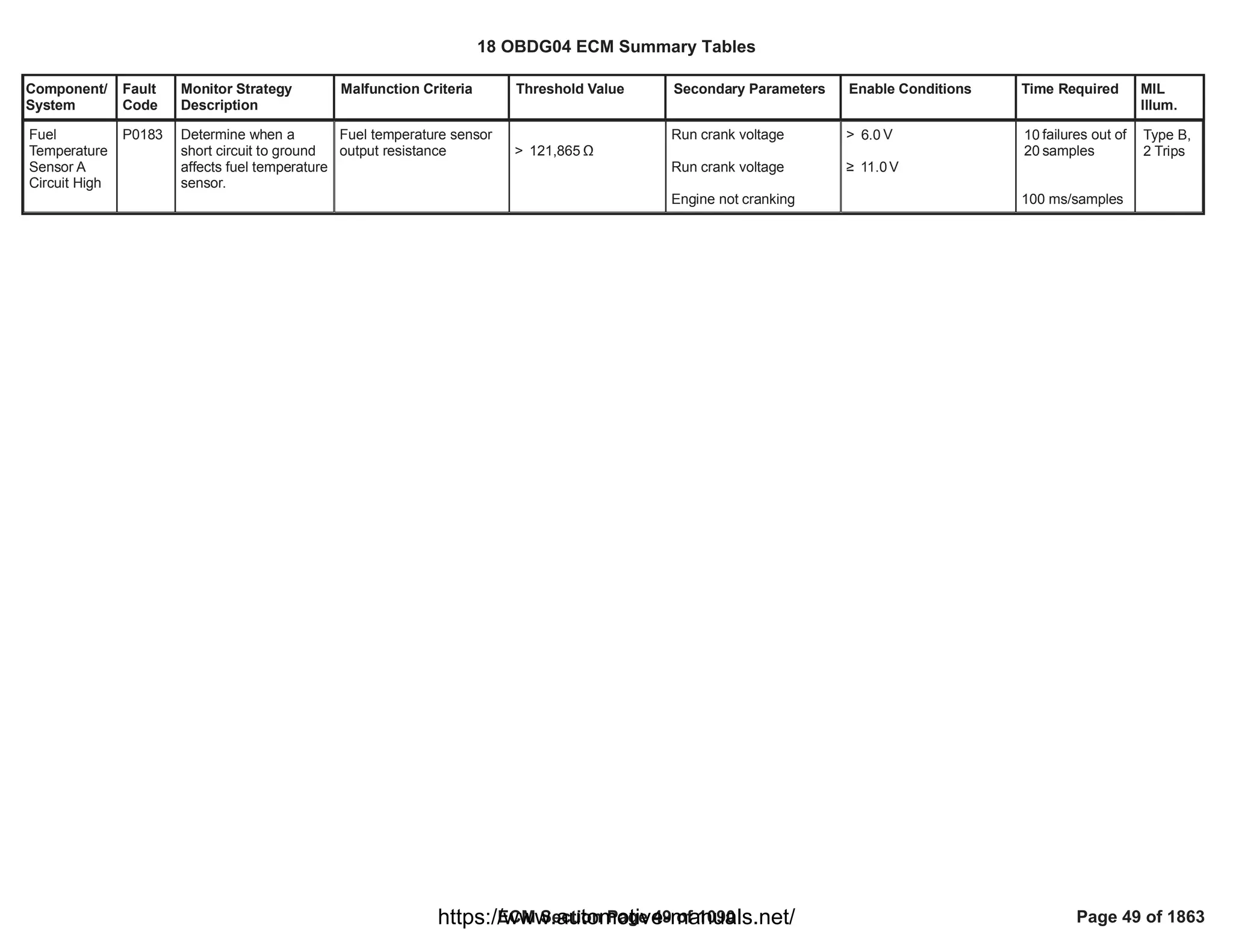
Fuel temperature > (1 - Į) * °C +
156
(Last good sample * Į)
with Į = e^[- (amount
of consecutive bad
samples * )]
0.01
Run crank voltage
Run crank voltage
No active DTC:
> V
6.0
• V
11.0
FTS_FTS_CktFA
failures out of
10
samples
15
100 ms/samples
Fuel
Temperature
Sensor A
Circuit
Intermittent
P0184 Determine when fuel
temperature sensor
changes quicker than
expected, likely due to
an intermittent fault.
Type B,
2 Trips
Fuel temperature < (1 - Į) * °C +
-56
(Last good sample * Į)
with Į = e^[- (amount
of consecutive bad
samples * )]
0.01
Run crank voltage
Run crank voltage
No active DTC:
> V
6.0
• V
11.0
FTS_FTS_CktFA
failures out of
10
samples
15
100 ms/samples
18 OBDG04 ECM Summary Tables
ECM Section Page 50 of 1090 Page 50 of 1863
https://www.automotive-manuals.net/](https://image.slidesharecdn.com/gmcenginefaultcodesdtc1-230327071418-56d3c5bb/75/18-OBDG04-ECM-Summary-Tables-50-2048.jpg)
![Component/
System
Fault
Code
Monitor Strategy
Description
Malfunction Criteria Threshold Value Secondary Parameters Enable Conditions Time Required MIL
Illum.
Fuel
Pressure
Sensor "B"
Circuit
Range/
Performance
P018B This DTC detects a fuel
pressure sensor
response stuck within
the normal operating
range using an
intrusive test ( as
follows)
a] Intrusive Test
Trigger: 1] Fuel Pump
Duty Cycle Clamped
Time ( min or max duty
cycle) >= 5 sec
Or 2] Fuel Pres Err
Variance <= calibration
value
KeFDBR_cmp_FPSS_
MinPres
Variance ;
Otherwise, Report
status as Pass
b] Intrusive test freq
limit: 60 sec between
intrusive tests that
pass,
c] Intrusive test Fuel
Flow limit: Fuel Flow
Actual < Max allowed
Fuel Flow rate
Sensed fuel pressure
change
[absolute value, during
intrusive test]
<= 30 kPa a) Diagnostic enabled
[FDBR_b_FPSS_DiagEnb
ld]
b) Timer Engine Running
[FDBR_t_EngModeRunC
oarse]
c1) Fuel Flow Rate Valid
c2)
FDB_FuelPresSnsrCktFA
c3) Reference Voltage
Fault Status [DTC P0641]
c4) FAB_FuelPmpCktFA
c5) Fuel Control Enable
Fault Active [DTC P12A6]
c6) Fuel Pump Driver
Module OverTemp Fault
Active [DTC P1255]
c7) Fuel Pump Speed
Fault Active [DTC P129F]
c8) CAN Sensor Bus
message $0C3 Comm
Fault
[CFMR_b_FTZM_Info1_U
codeCmFA DTC P165C]
c9) CAN Sensor Bus Fuel
Pmp Spd Command ARC
and Checksum Comm
Fault Code
[CFMR_b_FTZM_Cmd1_
UcodeCmFA DTC]
a) == TRUE
b) >= seconds
5.00
c1) == TRUE
c2) <> TRUE
c3) <> TRUE
c4] <> TRUE
c5) <> TRUE
c6) <> TRUE
c7) <> TRUE
c8) <> TRUE
c9] <> TRUE
1 sample /
12.5 millisec
Intrusive Test
Duration:
Fuel Flow -
related ( 5 to 12
sec)
Type B,
2 Trips
18 OBDG04 ECM Summary Tables
ECM Section Page 51 of 1090 Page 51 of 1863
https://www.automotive-manuals.net/](https://image.slidesharecdn.com/gmcenginefaultcodesdtc1-230327071418-56d3c5bb/75/18-OBDG04-ECM-Summary-Tables-51-2048.jpg)
![Component/
System
Fault
Code
Monitor Strategy
Description
Malfunction Criteria Threshold Value Secondary Parameters Enable Conditions Time Required MIL
Illum.
c10) Fuel Pump Duty
Cycle Fault Active
c11) Sensor Configuration
[FDBR_e_FuelPresSnsrC
onfig]
c12) Sensor Bus Relay
On
d) Emissions Fuel Level
Low [Message $3FB]
e) Fuel Control Enable
f) Fuel Pump Control
State
g) Instantaneous Fuel
Flow
[FCBR_dm_InstFuelFlow]
h) Diagnostic System
Disabled
[DRER_b_DiagSysDsb]
j1) Fuel Pmp Speed
Command Alive Rolling
Count and Checksum
Error [CAN Bus B $0CE]
[CFMR_b_FTZM_Cmd1_
ARC_ChkErr DTC]
j2) CAN Sensor Bus
message $0C3_Available
j3) Fuel Pres Sensor Ref
Voltage Status Message
Counter Incorrect Alive
Rolling Count and
c10) <> TRUE
c11) ==
CeFDBR_e_WiredTo_FT
ZM
c12) == TRUE
d) <> TRUE
e) == TRUE
f) == Normal Control
OR
== Fuel Pres Sensor
Stuck Control
g) >= gm/sec
0.05
h) <> TRUE
j1) <> TRUE
j2) == TRUE
j3) <> TRUE
18 OBDG04 ECM Summary Tables
ECM Section Page 52 of 1090 Page 52 of 1863
https://www.automotive-manuals.net/](https://image.slidesharecdn.com/gmcenginefaultcodesdtc1-230327071418-56d3c5bb/75/18-OBDG04-ECM-Summary-Tables-52-2048.jpg)
![Component/
System
Fault
Code
Monitor Strategy
Description
Malfunction Criteria Threshold Value Secondary Parameters Enable Conditions Time Required MIL
Illum.
Checksum Error [CAN
Bus B $0C3]
[CFMR_b_FTZM_Info1_A
RC_ChkErr DTC]
18 OBDG04 ECM Summary Tables
ECM Section Page 53 of 1090 Page 53 of 1863
https://www.automotive-manuals.net/](https://image.slidesharecdn.com/gmcenginefaultcodesdtc1-230327071418-56d3c5bb/75/18-OBDG04-ECM-Summary-Tables-53-2048.jpg)
![Component/
System
Fault
Code
Monitor Strategy
Description
Malfunction Criteria Threshold Value Secondary Parameters Enable Conditions Time Required MIL
Illum.
Fuel Pressure Sensor
output %
[re. full range as percent
of 5.0V reference]
< %
4.00
or
[0 kPa gauge]
a) Diagnostic enabled
[FDBR_b_FPSnsrCktLoDi
agEnbl]
b) Run_Crank Active
[PMDR_b_RunCrankActiv
e
c) Diagnostic System
Disabled
[DRER_b_DiagSysDsbl]
d) Pressure Sensor
Configuration
[FDBR_e_FuelPresSnsrC
onfig]
a) == TRUE
b) == TRUE
c) <> TRUE
d1) IF calibration
CeFDBR_e_WiredTo_FT
ZM
== WiredTo ECM
d2) IF NOT, then see
Case2
failures /
64.00
samples
80.00
1 sample/12.5
ms
Fuel
Pressure
Sensor "B"
Circuit Low
P018C This DTC detects if the
fuel pressure sensor
circuit is shorted low
Values are analyzed as
percent of sensor
reference voltage [[Abs
[5.0V -
SensorVoltsActual] /
5.0V] *100%]
Type B,
2 Trips
Fuel Pressure Sensor
output %
[re. full range as percent
of 5.0V reference]
< %
4.00
or
[0 kPa gauge]
a) Diagnostic enabled
[FDBR_b_FPSnsrCktLoDi
agEnbl]
b) Run_Crank Active
[PMDR_b_RunCrankActiv
e
c) Diagnostic System
Disabled
[DRER_b_DiagSysDsbl]
d1) Pressure Sensor
Configuration
[FDBR_e_FuelPresSnsrC
onfig]
d2) Sensor Bus Relay On
d3) CAN Sensor Bus
message $0C3_Available
d4) Fuel Pres Sensor Ref
a) == TRUE
b) == TRUE
c) <> TRUE
d1) IF calibration
CeFDBR_e_WiredTo_FT
ZM
== WiredTo FTZM
d2) == TRUE
d3) == TRUE
d4) <> TRUE
failures /
64.00
samples
80.00
1 sample/12.5
ms
18 OBDG04 ECM Summary Tables
ECM Section Page 54 of 1090 Page 54 of 1863
https://www.automotive-manuals.net/](https://image.slidesharecdn.com/gmcenginefaultcodesdtc1-230327071418-56d3c5bb/75/18-OBDG04-ECM-Summary-Tables-54-2048.jpg)
![Component/
System
Fault
Code
Monitor Strategy
Description
Malfunction Criteria Threshold Value Secondary Parameters Enable Conditions Time Required MIL
Illum.
Voltage Status Message
Counter Incorrect Alive
Rolling Count and
Checksum Error [CAN
Bus B $0C3]
[CFMR_b_FTZM_Info1_A
RC_ChkErr DTC]
d2) IF calibration
CeFDBR_e_WiredTo_FT
ZM
<> WiredTo FTZM,
then see Case1
18 OBDG04 ECM Summary Tables
ECM Section Page 55 of 1090 Page 55 of 1863
https://www.automotive-manuals.net/](https://image.slidesharecdn.com/gmcenginefaultcodesdtc1-230327071418-56d3c5bb/75/18-OBDG04-ECM-Summary-Tables-55-2048.jpg)
![Component/
System
Fault
Code
Monitor Strategy
Description
Malfunction Criteria Threshold Value Secondary Parameters Enable Conditions Time Required MIL
Illum.
Fuel Pressure Sensor
output %
[re. full range as percent
of 5.0V reference]
> %
96.00
or
[743 kPa ga]
a) Diagnostic enabled
[FDBR_b_FPSnsrCktLoDi
agEnbl]
b) Run_Crank Active
[PMDR_b_RunCrankActiv
e
c) Diagnostic System
Disabled
[DRER_b_DiagSysDsbl]
d) Pressure Sensor
Configuration
[FDBR_e_FuelPresSnsrC
onfig]
a) == TRUE
b) == TRUE
c) <> TRUE
d1) IF calibration
CeFDBR_e_WiredTo_FT
ZM
== WiredTo ECM
d2) IF NOT, then see
Case2
failures /
64.00
samples
80.00
1 sample/12.5
ms
Fuel
Pressure
Sensor "B"
Circuit High
P018D This DTC detects if the
fuel pressure sensor
circuit is shorted High
Values are analyzed as
percent of sensor
reference voltage [[Abs
[5.0V -
SensorVoltsActual] /
5.0V] *100%]
Type B,
2 Trips
Fuel Pressure Sensor
output %
[re. full range as percent
of 5.0V reference]
> %
96.00
or
[743 kPa ga]
a) Diagnostic enabled
[FDBR_b_FPSnsrCktLoDi
agEnbl]
b) Run_Crank Active
[PMDR_b_RunCrankActiv
e
c) Diagnostic System
Disabled
[DRER_b_DiagSysDsbl]
d1) Pressure Sensor
Configuration
[FDBR_e_FuelPresSnsrC
onfig]
d2) Sensor Bus Relay On
d3) CAN Sensor Bus
message $0C3_Available
d4) Fuel Pres Sensor Ref
a) == TRUE
b) == TRUE
c) <> TRUE
d1) IF calibration
CeFDBR_e_WiredTo_FT
ZM
== WiredTo FTZM
d2) == TRUE
d3) == TRUE
d4) <> TRUE
failures /
64.00
samples
80.00
1 sample/12.5
ms
18 OBDG04 ECM Summary Tables
ECM Section Page 56 of 1090 Page 56 of 1863
https://www.automotive-manuals.net/](https://image.slidesharecdn.com/gmcenginefaultcodesdtc1-230327071418-56d3c5bb/75/18-OBDG04-ECM-Summary-Tables-56-2048.jpg)
![Component/
System
Fault
Code
Monitor Strategy
Description
Malfunction Criteria Threshold Value Secondary Parameters Enable Conditions Time Required MIL
Illum.
Voltage Status Message
Counter Incorrect Alive
Rolling Count and
Checksum Error [CAN
Bus B $0C3]
[CFMR_b_FTZM_Info1_A
RC_ChkErr DTC]
d2) IF calibration
CeFDBR_e_WiredTo_FT
ZM
<> WiredTo FTZM,
then see Case1
18 OBDG04 ECM Summary Tables
ECM Section Page 57 of 1090 Page 57 of 1863
https://www.automotive-manuals.net/](https://image.slidesharecdn.com/gmcenginefaultcodesdtc1-230327071418-56d3c5bb/75/18-OBDG04-ECM-Summary-Tables-57-2048.jpg)


![Component/
System
Fault
Code
Monitor Strategy
Description
Malfunction Criteria Threshold Value Secondary Parameters Enable Conditions Time Required MIL
Illum.
Turbocharge
r/
Supercharge
r "A"
Overboost
Condition
P0234 This monitor detects
failures in the charging
air system such to not
fulfill the request of
boost pressure in the
intake manifold. It
works only in steady
state closed loop
pressure control zone.
The DTC checks a
permanent negative
control deviation of the
boost pressure
indicating an overboost
condition.
This monitor is used to
detect any malfunction
in the boost pressure
system causing the
vehicle's emissions to
exceed the limits.
The aim of the
overboost pressure
monitor is to detect
obstructions in the
exhaust pipe. The
boost pressure is
usually controlled by
the VGT vanes. The
intake manifold
pressure is also
affected by the throttle
valve and the HP EGR
valve position changes.
The aim of this
procedure is to identify
a limitation of the VGT
vanes (equal to an
obstruction) that leads
to exceed the emission
limits.
Boost pressure tracking
error(difference between
the desired boost
pressure and the
measured pressure at
intake manifold by MAP
sensor) lower than a
threshold.
If throttle control is active:
The setpoint used for
closed loop control is the
conversion of the desired
upstream throttle boost
pressure (target) in
desired intake boost
pressure.
The conversion of the
setpoint is done
calculating the pressure
drop over the throttle
valve that is strictly
dependent on the valve
position.
If throttle control is NOT
active:
The setpoint used for
closed loop control is the
intake manifold pressure:
in this situation the
diagnostic monitors the
boost pressure closed
loop control tracking error.
If throttle control is
active (Refer to "Other
AICR DSL flags" Free
Form):
<
(
P0234: Negative
boost deviation
threshold (throttle
control active)
[kPa]
x
P0234, P2263:
Overboost
barometric correction
)
If throttle control is
NOT active (Refer to
"Other AICR DSL
flags" Free Form):
<
(
P0234: Negative
boost deviation
threshold (throttle
control not active)
[kPa]
x
P0234, P2263:
Overboost
barometric correction
)
Calibration on diagnostic
enabling
Engine Running
Cranking ignition in range
PT Relay voltage in range
Difficult launch NOT
detected
Boost Pressure Control
Closed Loop active
No active transition from a
combustion mode to
another one
Outside Air Temperature
in range
Desired Boost Pressure
steady state:
BstDes-BstDes_Old
P0234, P0299: Boost
pressure control
deviation enabling
==TRUE
==TRUE
Battery voltage > 11.00
[V]
Powertrain relay voltage >
[V]
11.00
Refer to
"LDT_DifficultLaunchActiv
e" Free Form
Refer to "Boost Control in
Closed Loop" Free Form
==TRUE
> [°C]
-7.00
AND
< [°C]
80.00
> [kPa/s]
-5
AND
< [kPa/s]
5
fail counters
320
over sample
400
counters
sampling time is
25ms
Type B,
2 Trips
18 OBDG04 ECM Summary Tables
ECM Section Page 63 of 1090 Page 63 of 1863
https://www.automotive-manuals.net/](https://image.slidesharecdn.com/gmcenginefaultcodesdtc1-230327071418-56d3c5bb/75/18-OBDG04-ECM-Summary-Tables-63-2048.jpg)
![Component/
System
Fault
Code
Monitor Strategy
Description
Malfunction Criteria Threshold Value Secondary Parameters Enable Conditions Time Required MIL
Illum.
Engine speed in range
Desired intake Boost
pressure in range
(Engine Coolant
Temperature
OR
OBD Coolant Enable
Criteria),
AND
Engine Coolant
Temperature
Ambient Air Pressure in
range
Throttle Valve position
> [rpm]
2,000.00
AND
< [rpm]
3,000.00
>
P0234: Minimum boost
pressure for overboost
monitor enabling
[kPa]
AND
<
P0234: Maximum boost
pressure for overboost
monitor enabling
[kPa]
> [°C]
60
==TRUE
< [°C]
124
> [kPa]
75
AND
< [kPa]
120
>= [%] if throttle
90.00
control is active (Refer to
"Other AICR DSL flags"
Free Form)
>= [%] if throttle
90.00
control is NOT active
(Refer to "Other AICR
DSL flags" Free Form)
18 OBDG04 ECM Summary Tables
ECM Section Page 64 of 1090 Page 64 of 1863
https://www.automotive-manuals.net/](https://image.slidesharecdn.com/gmcenginefaultcodesdtc1-230327071418-56d3c5bb/75/18-OBDG04-ECM-Summary-Tables-64-2048.jpg)
![Component/
System
Fault
Code
Monitor Strategy
Description
Malfunction Criteria Threshold Value Secondary Parameters Enable Conditions Time Required MIL
Illum.
No active DTCs
All enabling conditions
last for a time
AIC_BstSysDiagDenomD
sbl
==FALSE
>
P0234: Overboost
monitor delay timer
[s]
18 OBDG04 ECM Summary Tables
ECM Section Page 65 of 1090 Page 65 of 1863
https://www.automotive-manuals.net/](https://image.slidesharecdn.com/gmcenginefaultcodesdtc1-230327071418-56d3c5bb/75/18-OBDG04-ECM-Summary-Tables-65-2048.jpg)
![Component/
System
Fault
Code
Monitor Strategy
Description
Malfunction Criteria Threshold Value Secondary Parameters Enable Conditions Time Required MIL
Illum.
Turbocharge
r/
Supercharge
r "A"
Underboost
Condition
P0299 This monitor detects
failures in the charging
air system such to not
fulfill the request of
boost pressure in the
intake manifold. It
works only in steady
state closed loop
pressure control zone.
The DTC checks a
permanent positive
control deviation of the
boost pressure
indicating an
underboost condition.
This monitor is used to
detect any malfunction
in the boost pressure
system causing the
vehicle's emissions to
exceed the limits.
The aim of the
underboost pressure
monitor is to detect
leakages in the pipe
after the compressor or
in the intake/exhaust
manifold. The boost
pressure is usually
controlled by the VGT
vanes. The intake
manifold pressure is
also affected by the
throttle valve and the
HP EGR valve position
changes. The aim of
this procedure is to
identify a limitation of
the VGT vanes (equal
to a leakage) that leads
to exceed the emission
Boost pressure tracking
error(difference between
the desired boost
pressure and the
measured pressure at
intake manifold by MAP
sensor) higher than a
threshold.
If throttle control is active:
The setpoint used for
closed loop control is the
conversion of the desired
upstream throttle boost
pressure (target) in
desired intake boost
pressure.
The conversion of the
setpoint is done
calculating the pressure
drop over the throttle
valve that is strictly
dependent on the valve
position.
If throttle control is NOT
active:
The setpoint used for
closed loop control is the
intake manifold pressure:
in this situation the
diagnostic monitors the
boost pressure closed
loop control tracking error.
If throttle control is
active (Refer to "Other
AICR DSL flags" Free
Form):
>
(
P0299: Positive boost
deviation threshold
(throttle control
active)
[kPa]
x
P0299, P2263:
Underboost
barometric correction
)
If throttle control is
NOT active (Refer to
"Other AICR DSL
flags" Free Form):
>
(
P0299: Positive boost
deviation threshold
(throttle control not
active)
[kPa]
x
P0299, P2263:
Underboost
barometric correction
)
Calibration on diagnostic
enabling
Engine Running
Cranking ignition in range
PT Relay voltage in range
Difficult launch NOT
detected
Boost Pressure Control
Closed Loop active
No active transition from a
combustion mode to
another one
Outside Air Temperature
in range
Desired Boost Pressure
steady state:
BstDes-BstDes_Old
P0234, P0299: Boost
pressure control
deviation enabling
==TRUE
==TRUE
Battery voltage > 11.00
[V]
Powertrain relay voltage >
[V]
11.00
Refer to
"LDT_DifficultLaunchActiv
e" Free Form
Refer to "Boost Control in
Closed Loop" Free Form
==TRUE
> [°C]
-7.00
AND
< [°C]
80.00
> [kPa/s]
-5
AND
< [kPa/s]
5
fail
320.00
counters over
sample
400.00
counters
sampling time is
25ms
Type B,
2 Trips
18 OBDG04 ECM Summary Tables
ECM Section Page 66 of 1090 Page 66 of 1863
https://www.automotive-manuals.net/](https://image.slidesharecdn.com/gmcenginefaultcodesdtc1-230327071418-56d3c5bb/75/18-OBDG04-ECM-Summary-Tables-66-2048.jpg)
![Component/
System
Fault
Code
Monitor Strategy
Description
Malfunction Criteria Threshold Value Secondary Parameters Enable Conditions Time Required MIL
Illum.
limits. Engine speed in range
Desired intake Boost
pressure in range
(Engine Coolant
Temperature
OR
OBD Coolant Enable
Criteria),
AND
Engine Coolant
Temperature
Ambient Air Pressure in
range
Throttle Valve position
> [rpm]
1,200.00
AND
< [rpm]
2,200.00
>
P0299: Minimum boost
pressure for underboost
monitor enabling
[kPa]
AND
<
P0299: Maximum boost
pressure for underboost
monitor enabling
[kPa]
> [°C]
60
==TRUE
< [°C]
124
> [kPa]
75
AND
< [kPa]
120
>= [%] if throttle
90.00
control is active (Refer to
"Other AICR DSL flags"
Free Form)
>= [%] if throttle
90.00
control is NOT active
(Refer to "Other AICR
DSL flags" Free Form)
18 OBDG04 ECM Summary Tables
ECM Section Page 67 of 1090 Page 67 of 1863
https://www.automotive-manuals.net/](https://image.slidesharecdn.com/gmcenginefaultcodesdtc1-230327071418-56d3c5bb/75/18-OBDG04-ECM-Summary-Tables-67-2048.jpg)
![Component/
System
Fault
Code
Monitor Strategy
Description
Malfunction Criteria Threshold Value Secondary Parameters Enable Conditions Time Required MIL
Illum.
No active DTCs
All enabling conditions
last for a time
AIC_BstSysDiagDenomD
sbl
==FALSE
>
P0299: Underboost
monitor delay timer
[s]
18 OBDG04 ECM Summary Tables
ECM Section Page 68 of 1090 Page 68 of 1863
https://www.automotive-manuals.net/](https://image.slidesharecdn.com/gmcenginefaultcodesdtc1-230327071418-56d3c5bb/75/18-OBDG04-ECM-Summary-Tables-68-2048.jpg)


![Component/
System
Fault
Code
Monitor Strategy
Description
Malfunction Criteria Threshold Value Secondary Parameters Enable Conditions Time Required MIL
Illum.
Exhaust Gas
Recirculation
(EGR) Flow
insufficient
P0401 This monitor detects
failures in the air
system such to not
fulfill the request of
mass air flow through
the intake circuit.
This monitor is used to
detect any malfunction
in the air system that
leads to lower EGR
rate causing the
vehicle's emissions to
exceed the OBD limits.
The aim of the EGR
flow monitor is to detect
HP EGR obstructions
(insufficient EGR flow).
The EGR flow depends
on several variables
like the HP EGR valve
position, intake
manifold pressure,
exhaust pressure, EGR
cooler outlet
temperature. The aim
of this procedure is to
identify a limitation of
the HP EGR (equal to
an obstruction) that
leads to exceed the
OBD limits.
Air mass tracking error:
difference between the
fresh air requested (set
point) and the fresh air
measured by MAF sensor.
<
(
SeaBaro Constant
x
P0401: Insufficient
EGR flow barometric
table B (sea level)
[mg]
)
+
(
MidBaro Constant
x
P0401: Insufficient
EGR flow barometric
table B (mid level)
[mg]
)
+
(
LoBaro Constant
x
P0401: Insufficient
EGR flow barometric
table B (low level)
[mg]
)
+
(
SeaBaro Constant
x
Calibration on diagnostic
enabling
HP EGR control is in
closed loop on air flow
OR
LP EGR (if present)
control is in closed loop
on air flow
OR
Diagnostic enabled by
calibration when HP/LP
EGR control is in closed
loop on HP/LP EGR flow
Engine Running
Cranking ignition in range
PT Relay voltage in range
Air Control is Active (air
control in closed loop)
Desired EGR rate
Engine speed is steady
state: |RPM-RPM_old|
for a minimum number of
samples
P0401, P0402: EGR flow
monitor enabling
==TRUE
Refer to "Other AICR DSL
flags" Free Form
==TRUE
1.00
==TRUE
Battery voltage > 11.00
[V]
Powertrain relay voltage >
[V]
11.00
Refer to "Air Control
Active" Free Form
> 0 [%]
<= [rpm]
17
> [counts]
35
fail
350.00
counters over
sample
435.00
counters
sampling time is
25 ms
Type B,
2 Trips
18 OBDG04 ECM Summary Tables
ECM Section Page 91 of 1090 Page 91 of 1863
https://www.automotive-manuals.net/](https://image.slidesharecdn.com/gmcenginefaultcodesdtc1-230327071418-56d3c5bb/75/18-OBDG04-ECM-Summary-Tables-91-2048.jpg)
![Component/
System
Fault
Code
Monitor Strategy
Description
Malfunction Criteria Threshold Value Secondary Parameters Enable Conditions Time Required MIL
Illum.
P0401: Insufficient
EGR flow barometric
table A (sea level)
[mg]
x
P0401: Insufficient
EGR flow barometric
correction (sea level)
)
+
(
MidBaro Constant
x
P0401: Insufficient
EGR flow barometric
table A (mid level)
[mg]
x
P0401: Insufficient
EGR flow barometric
correction (mid level)
)
+
(
LoBaro Constant
x
P0401: Insufficient
EGR flow barometric
table A (low level)
[mg]
x
P0401: Insufficient
EGR flow barometric
correction (low level)
)
Fuel request is steady
state: |FUEL-FUEL_old|
for a minimum number of
samples
An air control transition
has ended
OR
Such condition is disabled
by calibration
No active transition from a
combustion mode to
another one
Throttle measured
position
Outside Air Temperature
Ambient Pressure
Engine Coolant
Temperature
OR
OBD Coolant Enable
Criteria
Desired EGR flow
<= [mm^3]
0.70
> [counts]
35
Refer to "Air Control
Transition"Free Form
OR
==TRUE
1.00
==TRUE
> [%]
90.00
> [°C]
-7.00
> [kPa]
74.80
> [°C]
60.00
==TRUE
>
P0401: Minimum
desired EGR flow
[mg]
18 OBDG04 ECM Summary Tables
ECM Section Page 92 of 1090 Page 92 of 1863
https://www.automotive-manuals.net/](https://image.slidesharecdn.com/gmcenginefaultcodesdtc1-230327071418-56d3c5bb/75/18-OBDG04-ECM-Summary-Tables-92-2048.jpg)
![Component/
System
Fault
Code
Monitor Strategy
Description
Malfunction Criteria Threshold Value Secondary Parameters Enable Conditions Time Required MIL
Illum.
Desired fuel quantity
Engine speed
No faults on proper
temperature sensor
All enabling conditions
last for a time
> [mm^3]
7.50
AND
< [mm^3]
45.00
> [rpm]
1,200.00
AND
< [rpm]
2,500.00
AIC_EGR_FlowDiagAirTe
mpFA
==FALSE
> [s]
0.00
18 OBDG04 ECM Summary Tables
ECM Section Page 93 of 1090 Page 93 of 1863
https://www.automotive-manuals.net/](https://image.slidesharecdn.com/gmcenginefaultcodesdtc1-230327071418-56d3c5bb/75/18-OBDG04-ECM-Summary-Tables-93-2048.jpg)
![Component/
System
Fault
Code
Monitor Strategy
Description
Malfunction Criteria Threshold Value Secondary Parameters Enable Conditions Time Required MIL
Illum.
Warm Up
Catalyst
Efficiency
Below
Threshold
Bank 1
(OBD2, Cold
start based
monitor)
P0421 Cold start based
monitor: the Catalyst
(CC DOC) monitor only
runs at cold start when
dedicated conditions to
detect this situation are
satisfied. The
diagnostic takes
advantage of the
HydroCarbon stored in
the cold phase (the
proper combination of
combustion mode and
injection pattern is
requested in order to
accumulate the proper
amount of HC for
performing a robust
monitoring) and
evaluates the energy
produced by Catalyst
during the following
oxidation process
(once that light-off
temperature is fulfilled).
The so calculated
released energy is
compared to the
energy provided at CC
DOC inlet in order to
rescale the efficiency
index value. Some
corrections to minimize
the results dispersion
are finally applied.
EWMA Filtering
functionality (including
Fast Initial Response
(FIR), Rapid Response
(RR) and EWMA
Catalyst Efficiency Index
< Threshold
If
- Catalyst EWMA filter
enabling calibration =
TRUE
AND
- Catalyst conversion
inefficiency previously
detected (Catalyst Fault
Active = TRUE)
Then:
Catalyst Efficiency Index
< Repass Threshold
Efficiency Index <
CatCrtdEffThrsh
[Curve]
If
EWMA Enbl Cal =
[Boolean]
1.00
AND
Catalyst FA =
CAT_CatSysEffLoB1_F
A
Then:
Efficiency Index <
CatCrtdEffRepEWMA
[Curve]
Catalyst monitor is
enabled if:
- Catalyst monitor
enabling calibrations =
TRUE
AND
- No active DTCs:
Catalyst up temperature
sensor not in fault (Fault
Flag = FALSE)
AND
Catalyst down
temperature sensor not in
fault (Fault Flag = FALSE)
AND
Catalyst up exhaust flow
estimation not in fault
(Fault Flag = FALSE)
AND
Injection system not in
fault (Fault Flag = FALSE)
AND
Ambient temperature
information not in fault
(Fault Active = FALSE)
AND
Vehicle speed information
not in fault (Fault Active =
FALSE)
AND
Catalyst down
hydrocarbon estimation
Catalyst monitor is
enabled if:
Cat Monitor Enbl Cal =
ColdStartMontrEnbl
[Boolean]
AND
ColdStartMonitorSelected
= [Boolean]
1.00
AND
ReportingEnabled = 1.00
[Boolean]
AND
No active DTCs
[Boolean]:
Cat Up Temp Snsr Flt =
NOT ( )
EGT_SnsrCatUpFlt
AND
Cat Dwn Temp Snsr Flt =
NOT
( )
EGT_SnsrCatDwnFlt
AND
Cat Up Exh Flow Flt =
NOT
( )
EXF_TotExhCatUpFlt
AND
Injection System Flt =
NOT
( )
FUL_GenericInjSysFlt
AND
Amb Temp FA = NOT
( )
OAT_PtEstFiltFA
AND
Veh Speed FA = NOT
(VehicleSpeedSensor_FA
)
AND
Cat Dwn HC Flt = NOT
( )
CAT_HC_CatDwnFlt
Task Time = 100
[ms]
If
- Catalyst EWMA
filter enabling
cailibration =
FALSE (EWMA
Enbl Cal = 1.00
[Boolean])
Then:
2 trips (with
malfunction) to
set DTC (Type
B)
If
- Catalyst EWMA
filter enabling
cailibration =
TRUE (EWMA
Enbl Cal = 1.00
[Boolean])
AND
- EWMA status =
EWMA Standard
Then:
1 trip (with
malfunction) to
set DTC (Type A)
If
- Catalyst EWMA
filter enabling
cailibration =
TRUE (EWMA
Enbl Cal = 1.00
[Boolean])
Type A,
1 Trips
18 OBDG04 ECM Summary Tables
ECM Section Page 94 of 1090 Page 94 of 1863
https://www.automotive-manuals.net/](https://image.slidesharecdn.com/gmcenginefaultcodesdtc1-230327071418-56d3c5bb/75/18-OBDG04-ECM-Summary-Tables-94-2048.jpg)
![Component/
System
Fault
Code
Monitor Strategy
Description
Malfunction Criteria Threshold Value Secondary Parameters Enable Conditions Time Required MIL
Illum.
Standard) is supported
by the Catalyst (CC
DOC) monitor.
In MY18 sw the
mentioned monitor runs
in the following below
exhaust configurations:
- C_DPF_UI_SCR:
Close Coupled DOC
(Catalyst) --> Diesel
Particulate Filter -->
Urea Injector -->
Selective Catalyst
Reduction
not in fault (Fault Flag =
FALSE)
AND
Soaking time information
not in fault (Fault Active =
FALSE)
AND
Engine coolant
temperature information
not in fault (Fault Flag =
FALSE)
AND
- Ambient conditions
always satisfied while
engine running:
Ambient pressure higher
than calibration
AND
Ambient temperature
higher than calibration
AND
- Cold start conditions
detected at key on:
Engine coolant
temperature lower or
equal than calibration
AND
Catalyst down exhaust
temperature (by sensor)
lower or equal than
calibration
AND
Soaking time higher or
equal than calibration
AND
Catalyst stored
HydroCarbon quantity
lower or equal than
calibration
AND
Eng Mode Not Run Timer
= NOT
(
EngineModeNotRunTimer
_FA
)
AND
Eng Cool Temp Flt = NOT
( &
ECT_Sensor_FA
)
ECT_Sensor_TFTKO
AND
Ambient conditions
always satisfied while
engine running [Boolean]:
Amb Press > [KPa]
74.80
AND
Amb Temp > [K]
266.00
AND
Cold start conditions
detected at key on
[Boolean]:
Eng Cool Temp <= 55.00
[°C]
AND
Cat Dwn Temp Snsr <=
[°C]
55.00
AND
Soak Time >= [s]
0.00
AND
Cat Stored HC <= 1.20
[g]
AND
- EWMA status =
Fast Initial
Response (FIR)
Then:
- 1 trip (with
malfunction) to
set DTC (Type A)
and return to
EWMA status =
EWMA Standard
- [Counter]
4.00
elapsed trips
(with no
mulfunction) to
report pass and
return to EWMA
status = EWMA
Standard
If
- Catalyst EWMA
filter enabling
cailibration =
TRUE (EWMA
Enbl Cal = 1.00
[Boolean])
AND
- EWMA status =
Rapid Response
(RR)
Then:
- 1 trip (with
malfunction) to
set DTC (Type A)
and return to
EWMA status =
EWMA Standard
- 1 trip (with no
mulfunction) to
report pass
18 OBDG04 ECM Summary Tables
ECM Section Page 95 of 1090 Page 95 of 1863
https://www.automotive-manuals.net/](https://image.slidesharecdn.com/gmcenginefaultcodesdtc1-230327071418-56d3c5bb/75/18-OBDG04-ECM-Summary-Tables-95-2048.jpg)
![Component/
System
Fault
Code
Monitor Strategy
Description
Malfunction Criteria Threshold Value Secondary Parameters Enable Conditions Time Required MIL
Illum.
AND
- Catalyst monitor not yet
performed successfully in
current driving cycle
(Catalyst monitor shall run
only once per driving
cycle):
Catalyst down estimated
temperature (by 1dk
thermal model) lower than
calibration
AND
- Catalyst monitor not
aborted in current driving
cycle:
Integration time
(monitoring time) lower
than calibration
AND
Integration time
(monitoring time) higher
or equal than calibration;
AND
- If enabled, HC
accumulation strategy
never disabled while the
monitor is running
Catalyst monitor
integration is enabled if:
- Catalyst up exhaust
temperature (by sensor)
higher than calibration
If Catalyst up exhaust
temperature (by sensor)
lower than calibration
integration is reset
AND
Catalyst monitor not yet
performed successfully in
current driving cycle
(Catalyst monitor shall run
only once per driving
cycle) [Boolean]:
Cat Dwn Temp (by 1dk
thermal model) < 180.00
[°C]
AND
Catalyst monitor not
aborted in current driving
cycle [Boolean]:
Integr Time (Montr Time)
< [s]
110.00
AND
Integr Time (Montr Time)
>= [samples at
320.00
task time];
AND
if HC accumulation
strategy enable cal ==
TRUE
then
AIC_CoolByp_DsblLateAf
t
== FALSE
Catalyst monitor
integration is enabled if:
Cat Up Temp Snsr >
[°C]
150.00
If Cat Up Temp Snsr <
[°C] integration is
140.00
reset
- [Counter]
2.00
elapsed trips
(with no
mulfunction) to
report pass and
return to EWMA
status = EWMA
Standard
18 OBDG04 ECM Summary Tables
ECM Section Page 96 of 1090 Page 96 of 1863
https://www.automotive-manuals.net/](https://image.slidesharecdn.com/gmcenginefaultcodesdtc1-230327071418-56d3c5bb/75/18-OBDG04-ECM-Summary-Tables-96-2048.jpg)
![Component/
System
Fault
Code
Monitor Strategy
Description
Malfunction Criteria Threshold Value Secondary Parameters Enable Conditions Time Required MIL
Illum.
Catalsyt monitor
integration is frozen if:
- Catalyst up exhaust flow
lower than calibration
If Catalyst up exhaust flow
higher than calibration
integration is re-enabled;
Diagnostic test
evaluation is triggered
if:
- Catalyst down estimated
temperature (by 1dk
thermal model) higher or
equal than calibration.
Catalsyt monitor
integration is frozen if:
Cat Up Exh Flow < 5.00
[g/s]
If Cat Up Exh Flow > 8.00
[g/s] integration is re-
enabled;
Diagnostic test
evaluation is triggered
if:
Cat Dwn Temp (by 1dk
thermal model) >=
[°C].
180.00
18 OBDG04 ECM Summary Tables
ECM Section Page 97 of 1090 Page 97 of 1863
https://www.automotive-manuals.net/](https://image.slidesharecdn.com/gmcenginefaultcodesdtc1-230327071418-56d3c5bb/75/18-OBDG04-ECM-Summary-Tables-97-2048.jpg)
![Component/
System
Fault
Code
Monitor Strategy
Description
Malfunction Criteria Threshold Value Secondary Parameters Enable Conditions Time Required MIL
Illum.
Cooling Fan
1 Relay
Control
Circuit Open
(Output
Driver
Monitor)
[Non- EREV]
P0480 Diagnoses the cooling
fan 1 relay control low
side driver circuit for
circuit faults
Voltage low during driver
off state (indicates open
circuit)
Open Circuit:
• 200 K Ÿ impedance
between signal and
controller ground
Powertrain Relay Voltage Voltage • volts
11.00 failures
50.00
out of 63.00
samples
100 ms / sample
Type B,
2 Trips
Note: In
certain
controlle
rs P0691
may also
set (Fan
1 Short
to
Ground).
18 OBDG04 ECM Summary Tables
ECM Section Page 101 of 1090 Page 101 of 1863
https://www.automotive-manuals.net/](https://image.slidesharecdn.com/gmcenginefaultcodesdtc1-230327071418-56d3c5bb/75/18-OBDG04-ECM-Summary-Tables-101-2048.jpg)


![Component/
System
Fault
Code
Monitor Strategy
Description
Malfunction Criteria Threshold Value Secondary Parameters Enable Conditions Time Required MIL
Illum.
5 Volt
Reference
#1 Circuit
P0641 Detects a continuous or
intermittent short on the
5 volt reference circuit
#1 by monitoring the
reference percent Vref1
and failing the
diagnostic when the
percent Vref1 is too low
or too high or if the
delta between the
filtered percent Vref1
and non-filtered
percent Vref1 is too
large. This diagnostic
only runs when battery
voltage is high enough.
ECM percent Vref1 <
or ECM percent Vref1 >
or the difference between
ECM filtered percent
Vref1 and percent Vref1 >
% Vref1
4.875
% Vref1
5.125
% Vref1
0.0495
Diagnostic enabled
AND
[
(Run/Crank voltage
for Time period AND
Starter engaged)
OR
(Run/Crank voltage AND
Starter engaged)
]
= 1
> Volts
6.41
= Seconds
0.02
= FALSE
> Volts
8.41
= TRUE
/
19 39
counts; or
0.1875
sec continuous;
12.5 ms/count in
main processor
Type A,
1 Trips
18 OBDG04 ECM Summary Tables
ECM Section Page 136 of 1090 Page 136 of 1863
https://www.automotive-manuals.net/](https://image.slidesharecdn.com/gmcenginefaultcodesdtc1-230327071418-56d3c5bb/75/18-OBDG04-ECM-Summary-Tables-136-2048.jpg)
![Component/
System
Fault
Code
Monitor Strategy
Description
Malfunction Criteria Threshold Value Secondary Parameters Enable Conditions Time Required MIL
Illum.
5 Volt
Reference
#2 Circuit
P0651 Detects a continuous or
intermittent short on the
5 volt reference circuit
#2 by monitoring the
reference percent Vref2
and failing the
diagnostic when the
percent Vref2 is too low
or too high or if the
delta between the
filtered percent Vref2
and non-filtered
percent Vref2 is too
large. This diagnostic
only runs when battery
voltage is high enough.
ECM percent Vref2 <
or ECM percent Vref2 >
or the difference between
ECM filtered percent
Vref2 and percent Vref2 >
% Vref2
4.875
% Vref2
5.125
% Vref2
0.0495
Diagnostic enabled
AND
[
(Run/Crank voltage
for Time period AND
Starter engaged)
OR
(Run/Crank voltage AND
Starter engaged)
]
= 1
> Volts
6.41
= Seconds
0.02
= FALSE
> Volts
8.41
= TRUE
/
19 39
counts; or
0.1875
sec continuous;
12.5 ms/count in
main processor
Type A,
1 Trips
18 OBDG04 ECM Summary Tables
ECM Section Page 138 of 1090 Page 138 of 1863
https://www.automotive-manuals.net/](https://image.slidesharecdn.com/gmcenginefaultcodesdtc1-230327071418-56d3c5bb/75/18-OBDG04-ECM-Summary-Tables-138-2048.jpg)


![Component/
System
Fault
Code
Monitor Strategy
Description
Malfunction Criteria Threshold Value Secondary Parameters Enable Conditions Time Required MIL
Illum.
5 Volt
Reference
#4 Circuit
P06A3 Detects a continuous or
intermittent short on the
5 volt reference circuit
#4 by monitoring the
reference percent Vref4
and failing the
diagnostic when the
percent Vref4 is too low
or too high or if the
delta between the
filtered percent Vref4
and non-filtered
percent Vref4 is too
large. This diagnostic
only runs when battery
voltage is high enough.
ECM percent Vref4 <
or ECM percent Vref4 >
or the difference between
ECM filtered percent
Vref4 and percent Vref4 >
% Vref4
4.875
% Vref4
5.125
% Vref4
0.0495
Diagnostic enabled
AND
[
(Run/Crank voltage
for Time period AND
Starter engaged)
OR
(Run/Crank voltage AND
Starter engaged)
]
= 1
> Volts
6.41
= Seconds
0.02
= FALSE
> Volts
8.41
= TRUE
/
19 39
counts; or
0.1875
sec continuous;
12.5 ms/count in
main processor
Type A,
1 Trips
18 OBDG04 ECM Summary Tables
ECM Section Page 148 of 1090 Page 148 of 1863
https://www.automotive-manuals.net/](https://image.slidesharecdn.com/gmcenginefaultcodesdtc1-230327071418-56d3c5bb/75/18-OBDG04-ECM-Summary-Tables-148-2048.jpg)
![Component/
System
Fault
Code
Monitor Strategy
Description
Malfunction Criteria Threshold Value Secondary Parameters Enable Conditions Time Required MIL
Illum.
Fail from passing state:
Oil Pressure delta is less
than a minimum delta
pressure on a state
change and the measured
filtered oil pressure is
above a threshold
Oil Pressure delta =
ABS [ Filtered Oil
Pressure at beginning
of state change -
filtered oil pressure
after seconds]
1.6
Oil Pressure delta
<
P06DD_P06DE_OP_S
tateChangeMin
AND
Filtered Oil Pressure
•
(
P0521_P06DD_P06D
E_OP_HiStatePressu
re
+
P06DD_P06DE_OP_L
oStatePressure
) ÷ 2
(see P06DD details on
Supporting Tables Tab
P06DD_P06DE_OP_S
tateChangeMin
P0521_P06DD_P06D
E_OP_HiStatePressu
re
P06DD_P06DE_OP_L
oStatePressure
)
Common Criteria:
Two Stage Oil Pump is
Present
Engine Running
Ambient Air Pressure
Oil Aeration
(= TRUE if engine speed
> RPM for longer
5,000
than seconds)
30.0
No active DTC's for
diagnsotic enable:
Check oil pump TFTKO
as a diagnostic enable
when Enabled.
No active DTC's for
control enable:
Active Criteria:
One Sided Performance
Test = Disabled
TRUE
• seconds
10.0
• kPa
70.0
FALSE
Fault bundles:
MAF_SensorFA
ECT_Sensor_FA
IAT_SensorFA
CrankSensor_FA
EngOilPressureSensorCkt
FA
AmbientAirDefault
EngOilTempFA
OilPmpTFTKO
:
Enabled OilPmpTFTKO
Fault bundles for
Enabled
control disable :
OilPmpTFTKO
EngineTorqueEstInaccura
te
EngOilPressureSensorFA
PowertrainRelayFault
CrankSensor_FA
EngOilTempFA
Disabled
• errors
4
out of samples.
5
Run once per trip
or activiated by
the Passive Test
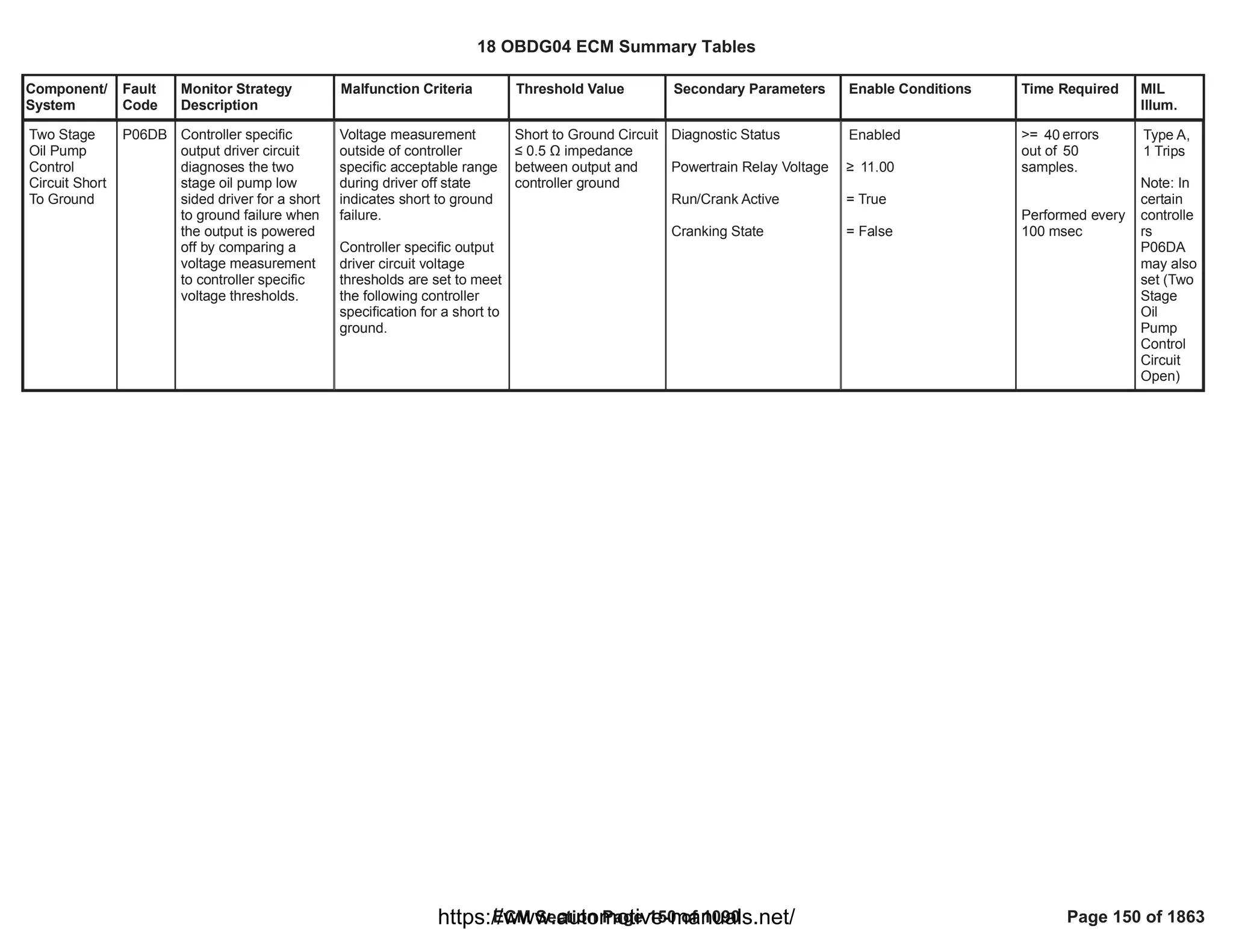
Two Stage
Oil Pump
Control
Circuit
Performance
- Two Sided
P06DD Diagnoses the two
stage oil pump is stuck
in the high pressure
state. This diagnostic
includes an intrusive
test and a passive test.
Intrusive test:
The oil pump control is
cycled off (high
pressure) and on (low
pressure) Y = 15 times
at calibratable intervals.
If a change in oil
pressure above a
calibration is not
detected then the oil
pressure is checked to
determine if it is stuck.
It takes X-out-of-Y
failures to fail and set
the appropriate code.
Passive test:
After the intrusive test
passes, then a passive
test will begin to run.
The passive test will
monitor the oil pressure
changes associated
with oil pump control
state changes. If the
passive test determines
that the oil pressure
change was less then
desired then the
intrusive test is
retriggered.
Type B,
2 Trips
18 OBDG04 ECM Summary Tables
ECM Section Page 152 of 1090 Page 152 of 1863
https://www.automotive-manuals.net/](https://image.slidesharecdn.com/gmcenginefaultcodesdtc1-230327071418-56d3c5bb/75/18-OBDG04-ECM-Summary-Tables-152-2048.jpg)
![Component/
System
Fault
Code
Monitor Strategy
Description
Malfunction Criteria Threshold Value Secondary Parameters Enable Conditions Time Required MIL
Illum.
Oil Pump in Low State
Modelled Oil Temperature
within range
Filtered Engine Speed
within range
Delta Filtered Engine
Speed within a range
Engine Torque within
range
Filtered Oil Pressure
within range
> seconds
1.6
deg C ” Oil Temp ”
50.0
deg C
100.0
RPM ” Filtered
1,400
Engine Speed ” 2,640
RPM
ABS [Filtered RPM at
beginning of State change
- Filtered RPM after 1.0
seconds ] ” RPM
50
P06DD_P06DE_MinEnab
leTorque_OP
”
Indicated Requested
Engine Torque
”
P06DD_P06DE_MaxEna
bleTorque_OP
(see P06DD details on
Supporting Tables Tab
P06DD_P06DE_MinEnab
leTorque_OP
)
P06DD_P06DE_MaxEna
bleTorque_OP
Filtered Engine Oil
Pressure >
P06DD_P06DE_MinOilPr
essThresh
(see P06DD details on
Supporting Tables Tab
P06DD_P06DE_MinOilPr
essThresh
)
18 OBDG04 ECM Summary Tables
ECM Section Page 153 of 1090 Page 153 of 1863
https://www.automotive-manuals.net/](https://image.slidesharecdn.com/gmcenginefaultcodesdtc1-230327071418-56d3c5bb/75/18-OBDG04-ECM-Summary-Tables-153-2048.jpg)
![Component/
System
Fault
Code
Monitor Strategy
Description
Malfunction Criteria Threshold Value Secondary Parameters Enable Conditions Time Required MIL
Illum.
Expected Oil Pressure
Delta within range
Passive Criteria:
Active Test Passed
Filtered Engine Speed
within range
Modelled Oil Temperature
within range
Delta Filtered Engine
Speed within a range
Oil Pressure Delta
within a range
kPa < ABS [
60.0
P0521_P06DD_P06DE_
OP_HiStatePressure
-
]
P06DD_P06DE_OP_LoS
tatePressure
< kPa
300.0
TRUE
RPM ” Filtered
1,000
Engine Speed ” 4,500
RPM
deg C ” Oil Temp ”
70.0
deg C
100.0
ABS [Filtered RPM at
beginning of State change
- Filtered RPM after 1.00
seconds ] ” RPM
1,000
Oil Pressure Delta
<
P06DD_P06DE_OP_Stat
eChangeMin
(see P06DD details on
Supporting Tables Tab
P06DD_P06DE_OP_Stat
eChangeMin
)
Fast Pass Condition
Oil Pressure delta is less
than a minimum delta
pressure on a state
change and the measured
filtered oil pressure is
Oil Pressure delta =
ABS [ Filtered Oil
Pressure at beginning
of state change -
Common Criteria:
Two Stage Oil Pump is
Present
Engine Running
TRUE
• seconds
10.0
0 errors
out of 5
samples.
Run once per trip
or activiated by
the Passive Test
18 OBDG04 ECM Summary Tables
ECM Section Page 154 of 1090 Page 154 of 1863
https://www.automotive-manuals.net/](https://image.slidesharecdn.com/gmcenginefaultcodesdtc1-230327071418-56d3c5bb/75/18-OBDG04-ECM-Summary-Tables-154-2048.jpg)
![Component/
System
Fault
Code
Monitor Strategy
Description
Malfunction Criteria Threshold Value Secondary Parameters Enable Conditions Time Required MIL
Illum.
above a threshold filtered oil pressure
after seconds]
1.6
Oil Pressure delta
<
P06DD_P06DE_OP_S
tateChangeMin
AND
Filtered Oil Pressure
•
(
P0521_P06DD_P06D
E_OP_HiStatePressu
re
-
P06DD_P06DE_OP_L
oStatePressure
) ÷ 2
(see P06DD details on
Supporting Tables Tab
P06DD_P06DE_OP_S
tateChangeMin
P0521_P06DD_P06D
E_OP_HiStatePressu
re
P06DD_P06DE_OP_L
oStatePressure
)
Ambient Air Pressure
Oil Aeration
(= TRUE if engine speed
> RPM for longer
5,000
than seconds)
30.0
No active DTC's for
diagnsotic enable:
Check oil pump TFTKO
as a diagnostic enable
when Enabled.
No active DTC's for
control enable:
Active Criteria:
One Sided Performance
Test = Disabled
Oil Pump in Low State
Modelled Oil Temperature
within range
Filtered Engine Speed
within range
• kPa
70.0
FALSE
Fault bundles:
MAF_SensorFA
ECT_Sensor_FA
IAT_SensorFA
EngOilPressureSensorCkt
FA
AmbientAirDefault
EngOilTempFA
OilPmpTFTKO
CrankSensor_FA
:
Enabled OilPmpTFTKO
Fault bundles for
Enabled
control disable :
OilPmpTFTKO
EngineTorqueEstInaccura
te
EngOilPressureSensorFA
PowertrainRelayFault
CrankSensor_FA
EngOilTempFA
Disabled
> seconds
1.6
deg C ” Oil Temp ”
50.0
deg C
100.0
RPM ” Filtered
1,400
Engine Speed ” 2,640
18 OBDG04 ECM Summary Tables
ECM Section Page 155 of 1090 Page 155 of 1863
https://www.automotive-manuals.net/](https://image.slidesharecdn.com/gmcenginefaultcodesdtc1-230327071418-56d3c5bb/75/18-OBDG04-ECM-Summary-Tables-155-2048.jpg)
![Component/
System
Fault
Code
Monitor Strategy
Description
Malfunction Criteria Threshold Value Secondary Parameters Enable Conditions Time Required MIL
Illum.
Engine Torque within
range
Delta Filtered Engine
Speed within a range
Filtered Oil Pressure
within range
Expected Oil Pressure
Delta within range
RPM
P06DD_P06DE_MinEnab
leTorque_OP
”
Indicated Requested
Engine Torque
”
P06DD_P06DE_MaxEna
bleTorque_OP
(see P06DD details on
Supporting Tables Tab
P06DD_P06DE_MinEnab
leTorque_OP
)
P06DD_P06DE_MaxEna
bleTorque_OP
ABS [Filtered RPM at
beginning of State change
- Filtered RPM after 1.0
seconds ] ” RPM
50
Filtered Engine Oil
Pressure >
P06DD_P06DE_MinOilPr
essThresh
(see P06DD details on
Supporting Tables Tab
P06DD_P06DE_MinOilPr
essThresh
)
kPa < ABS [
60.0
P0521_P06DD_P06DE_
OP_HiStatePressure
-
]
P06DD_P06DE_OP_LoS
tatePressure
< kPa
300.0
18 OBDG04 ECM Summary Tables
ECM Section Page 156 of 1090 Page 156 of 1863
https://www.automotive-manuals.net/](https://image.slidesharecdn.com/gmcenginefaultcodesdtc1-230327071418-56d3c5bb/75/18-OBDG04-ECM-Summary-Tables-156-2048.jpg)
![Component/
System
Fault
Code
Monitor Strategy
Description
Malfunction Criteria Threshold Value Secondary Parameters Enable Conditions Time Required MIL
Illum.
Fail from a passing state:
Oil Pressure delta is less
than a minimum delta
pressure on a state
change and the measured
filtered oil pressure is
below a threshold
Oil Pressure delta =
ABS [ Filtered Oil
Pressure at beginning
of state change -
filtered oil pressure
after seconds]
1.6
Oil Pressure delta
<
P06DD_P06DE_OP_S
tateChangeMin
(see P06DE details on
Supporting Tables Tab)
Filtered Oil Pressure
”
(
P0521_P06DD_P06D
E_OP_HiStatePressu
re
-
P06DD_P06DE_OP_L
oStatePressure
) ÷ 2
(see P06DE details on
Supporting Tables Tab)
Common Criteria:
Two Stage Oil Pump is
Present
Engine Running
Ambient Air Pressure
Oil Aeration
(= TRUE if engine speed
> RPM for longer
5,000
than seconds)
30.0
No active DTC's for
diagnsotic enable:
Check oil pump TFTKO
as a diagnostic enable
when Enabled.
No active DTC's for
control enable:
Active Criteria:
One Sided Performance
TRUE
• seconds
10.0
• kPa
70.0
FALSE
Fault bundles:
MAF_SensorFA
ECT_Sensor_FA
IAT_SensorFA
CrankSensor_FA
EngOilPressureSensorCkt
FA
AmbientAirDefault
EngOilTempFA
:
Enabled OilPmpTFTKO
Fault bundles for
Enabled
control disable :
OilPmpTFTKO
EngineTorqueEstInaccura
te
EngOilPressureSensorFA
PowertrainRelayFault
CrankSensor_FA
EngOilTempFA
Disabled
• errors
4
out of samples.
5
Run once per trip
or activiated by
the Passive Test
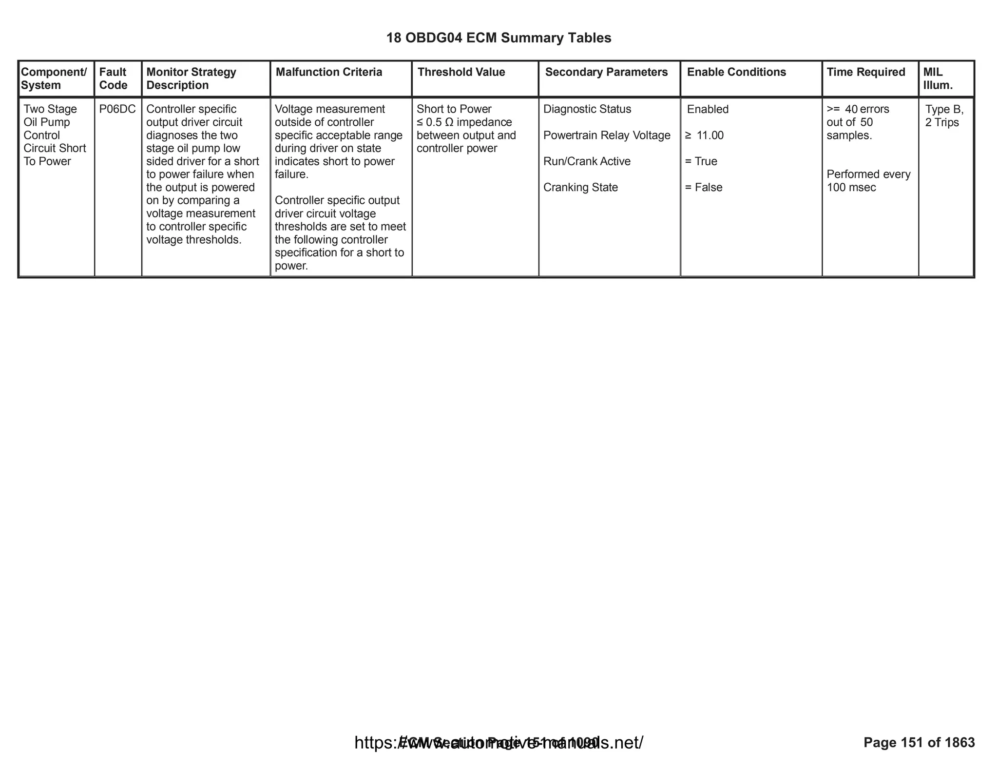
Two Stage
Oil Pump
Control
Circuit
StuckOn -
Two Sided
P06DE Diagnoses the two
stage oil pump is stuck
in the low pressure
state. This diagnostic
includes an intrusive
test and a passive test.
Intrusive test:
The oil pump control is
cycled off (high
pressure) and on (low
pressure) Y times at
calibratable intervals. If
a change in oil
pressure above a
calibration is not
detected then the oil
pressure is checked to
determine if it is stuck.
It takes X-out-of-Y
failures to fail and set
the appropriate code.
Passive test:
After the intrusive test
passes, then a passive
test will begin to run.
The passive test will
monitor the oil pressure
changes associated
with oil pump control
state changes. If the
passive test determines
that the oil pressure
change was less then
desired then the
intrusive test is
retriggered.
Type A,
1 Trips
18 OBDG04 ECM Summary Tables
ECM Section Page 157 of 1090 Page 157 of 1863
https://www.automotive-manuals.net/](https://image.slidesharecdn.com/gmcenginefaultcodesdtc1-230327071418-56d3c5bb/75/18-OBDG04-ECM-Summary-Tables-157-2048.jpg)
![Component/
System
Fault
Code
Monitor Strategy
Description
Malfunction Criteria Threshold Value Secondary Parameters Enable Conditions Time Required MIL
Illum.
Test = Disabled
Oil Pump in Low State
Modelled Oil Temperature
within range
Filtered Engine Speed
within range
Engine Torque within
range
Delta Filtered Engine
Speed within a range
Filtered Oil Pressure
within range
Expected Oil Pressure
Delta within range
> seconds
1.6
deg C ” Oil Temp ”
50.0
deg C
100.0
RPM ” Filtered
1,400
Engine Speed ” 2,640
RPM
P06DD_P06DE_MinEnab
leTorque_OP
”
Indicated Requested
Engine Torque
”
P06DD_P06DE_MaxEna
bleTorque_OP
(see P06DE details on
Supporting Tables Tab)
ABS [Filtered RPM at
beginning of State change
- Filtered RPM after 1.0
seconds ] ” RPM
50
Filtered Engine Oil
Pressure >
P06DD_P06DE_MinOilPr
essThresh
(see P06DD details on
Supporting Tables Tab)
kPa < ABS [
60.0
P0521_P06DD_P06DE_
OP_HiStatePressure
-
]
P06DD_P06DE_OP_LoS
tatePressure
< kPa
300.0
18 OBDG04 ECM Summary Tables
ECM Section Page 158 of 1090 Page 158 of 1863
https://www.automotive-manuals.net/](https://image.slidesharecdn.com/gmcenginefaultcodesdtc1-230327071418-56d3c5bb/75/18-OBDG04-ECM-Summary-Tables-158-2048.jpg)
![Component/
System
Fault
Code
Monitor Strategy
Description
Malfunction Criteria Threshold Value Secondary Parameters Enable Conditions Time Required MIL
Illum.
Passive Criteria:
Active Test Passed
Filtered Engine Speed
within range
Modelled Oil Temperature
within range
Delta Filtered Engine
Speed within a range
Oil Pressure Delta
<
P06DD_P06DE_OP_Stat
eChangeMin
(see P06DE details on
Supporting Tables Tab)
TRUE
RPM ” Filtered
1,000
Engine Speed ” 4,500
RPM
deg C ” Oil Temp ”
70.0
deg C
100.0
ABS [Filtered RPM at
beginning of State change
- Filtered RPM after
seconds ]
1.00
” RPM
1,000
TRUE
Fast Pass Condition
Oil Pressure delta is less
than a minimum delta
pressure on a state
change and the measured
filtered oil pressure is
below a threshold
Oil Pressure delta =
ABS [ Filtered Oil
Pressure at beginning
of state change -
filtered oil pressure
after seconds]
1.6
Oil Pressure delta
<
Common Criteria:
Two Stage Oil Pump is
Present
Engine Running
Ambient Air Pressure
Oil Aeration
(= TRUE if engine speed
TRUE
• seconds
10.0
• kPa
70.0
FALSE
0 errors
out of 5 samples.
Run once per trip
or activiated by
the Passive Test
18 OBDG04 ECM Summary Tables
ECM Section Page 159 of 1090 Page 159 of 1863
https://www.automotive-manuals.net/](https://image.slidesharecdn.com/gmcenginefaultcodesdtc1-230327071418-56d3c5bb/75/18-OBDG04-ECM-Summary-Tables-159-2048.jpg)
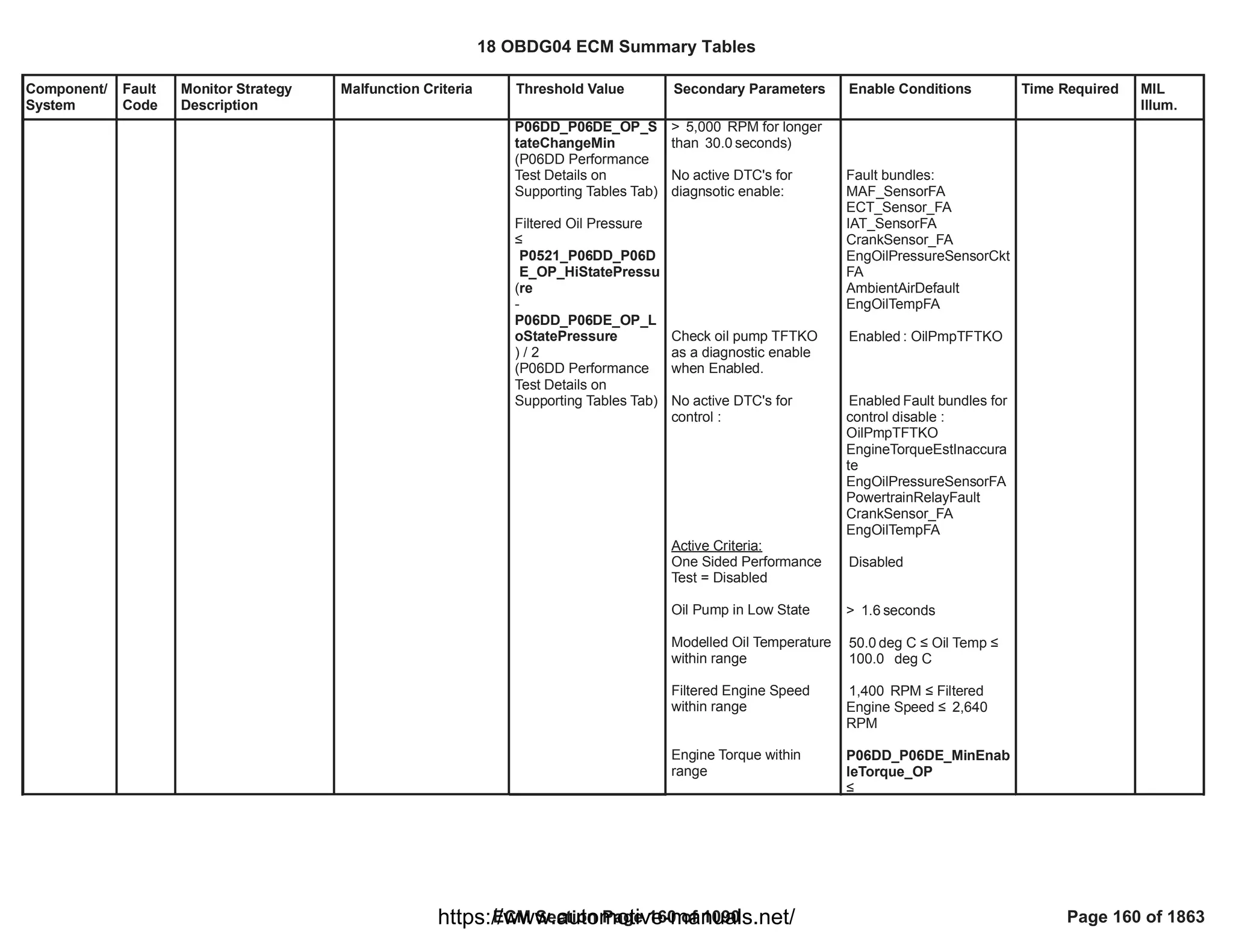
![Component/
System
Fault
Code
Monitor Strategy
Description
Malfunction Criteria Threshold Value Secondary Parameters Enable Conditions Time Required MIL
Illum.
Delta Filtered Engine
Speed within a range
Filtered Oil Pressure
within range
Expected Oil Pressure
Delta within range
Indicated Requested
Engine Torque
”
P06DD_P06DE_MaxEna
bleTorque_OP
(P06DD Performance Test
Details on Supporting
Tables Tab)
ABS [Filtered RPM at
beginning of State change
- Filtered RPM after 1.0
seconds ] ” RPM
50
Filtered Engine Oil
Pressure >
P06DD_P06DE_MinOilPr
essThresh
(see P06DD details on
Supporting Tables Tab)
kPa < ABS [
60.0
P0521_P06DD_P06DE_
OP_HiStatePressure
-
]
P06DD_P06DE_OP_LoS
tatePressure
< kPa
300.0
18 OBDG04 ECM Summary Tables
ECM Section Page 161 of 1090 Page 161 of 1863
https://www.automotive-manuals.net/](https://image.slidesharecdn.com/gmcenginefaultcodesdtc1-230327071418-56d3c5bb/75/18-OBDG04-ECM-Summary-Tables-161-2048.jpg)
![Component/
System
Fault
Code
Monitor Strategy
Description
Malfunction Criteria Threshold Value Secondary Parameters Enable Conditions Time Required MIL
Illum.
Fuel Pump
Phase U-V-
W Circuit
Open
P1029 This DTC detects if any
of the 3phase fuel
pump control circuits is
Open [system
configuration
"Brushless"]
The diagnostic can
detect open circuit
faults when the fuel
pump is not rotating. In
the "stopped" state,
small currents are
injected into each
motor phase circuit pair
by an internal fixed
source and
corresponding back-
EMF voltage is
monitored. A fault is
reported when the
monitored voltage falls
into a specific range
[adjusted for source
voltage]. This process
is completed in less
than 1 millisecond.
The FTZM ERFS
control samples back-
Electromotive Force
[EMF] for zero voltage-
level crossings as a
detection method to
enable closed loop
control brushless
commutation. Back
EMF is an electrical
characteristic of the
inactive phase of the 3-
phase signal wherein
only 2 phases are
Phased-pair circuit
voltage
3V <= V [back-EMF]
<= 6V
a) Sensed fuel pump
speed
b) Device configuration
FCBR_e_ChassisFuelPre
sSysType
c) Diagnostic Enabled -
KeFABR_b_OpenCktDiag
Enbl
d) CAN Sensor Bus
message $3EC_Avail
e) Sensor Bus Relay On
f) Sensor Bus B Message
$3EC Temp Signal
Message Counter
Incorrect
[CFMR_b_FTZM_Info7_A
RC_ChkErr]
a) == 0 RPM
b)
CeFCBR_e_DSL_ECM_F
TZM_BLDC_Sys
c) == TRUE
d) == TRUE
e) == TRUE
f) <> TRUE
failures /
40.00
80.00
samples
1 sample / 12.5
ms
Type A,
1 Trips
18 OBDG04 ECM Summary Tables
ECM Section Page 165 of 1090 Page 165 of 1863
https://www.automotive-manuals.net/](https://image.slidesharecdn.com/gmcenginefaultcodesdtc1-230327071418-56d3c5bb/75/18-OBDG04-ECM-Summary-Tables-165-2048.jpg)
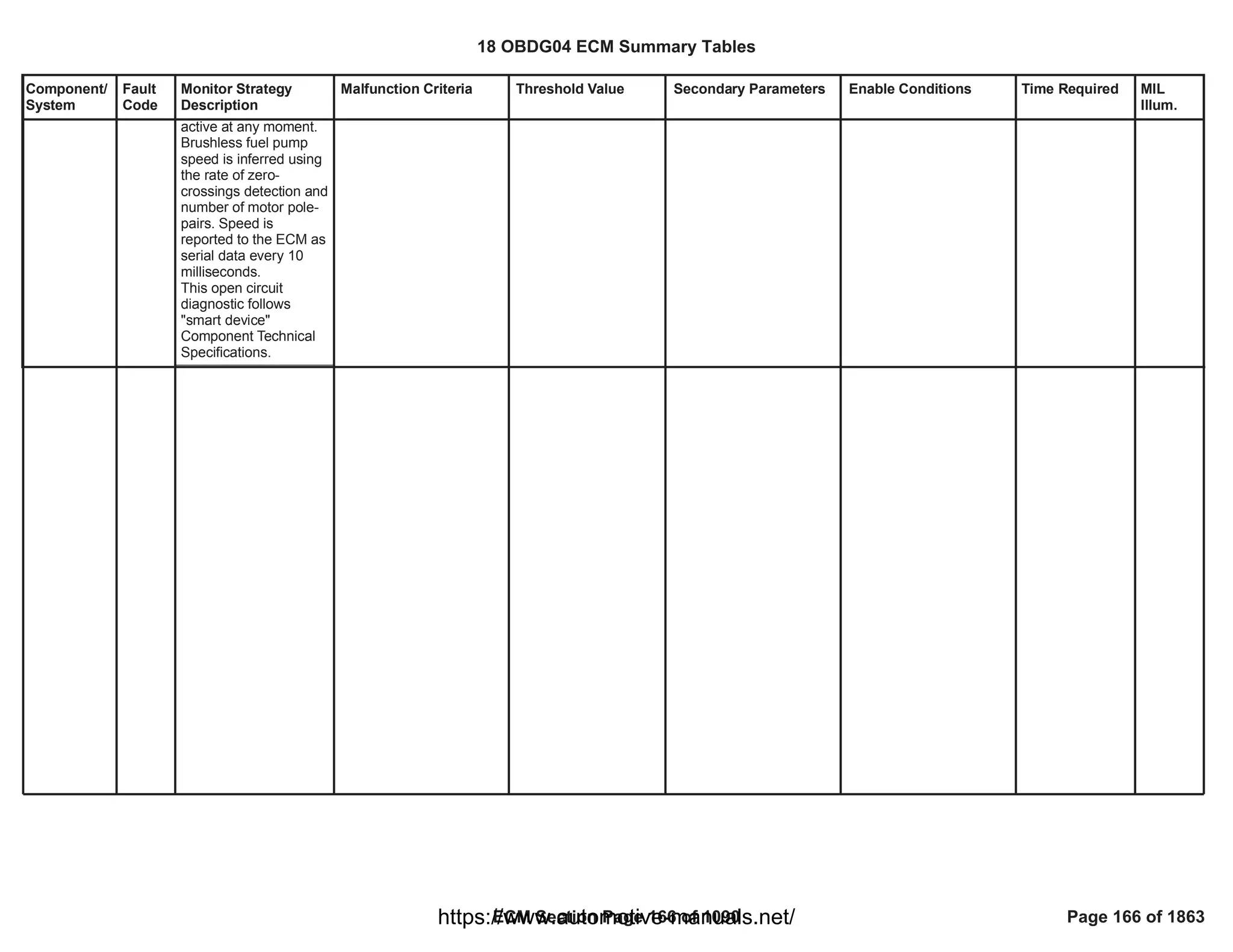
![Component/
System
Fault
Code
Monitor Strategy
Description
Malfunction Criteria Threshold Value Secondary Parameters Enable Conditions Time Required MIL
Illum.
Phased-pair circuit
voltage Difference
Vdelta > 0.145 V a) Device configuration
FCBR_e_ChassisFuelPre
sSysType
b) Diagnostic
KeFABR_b_GshtCktDiag
Enbl
c) CAN Sensor Bus
message $3EC_Avail
d) Sensor Bus Relay On
e) Sensor Bus Message
$3EC Temp Signal
Message Counter
Incorrect
[CFMR_b_FTZM_Info7_A
RC_ChkErr]
a) ==
CeFCBR_e_DSL_ECM_F
TZM_BLDC_Sys
b) == TRUE
c) == TRUE
d) == TRUE
e) <> TRUE
failures /
40.00
80.00
samples
1 sample / 12.5
ms
Fuel Pump
Phase U-V-
W Circuit
Low
P102A This DTC detects if the
fuel pump control
circuit is shorted to low
[Short to Ground]
The diagnostic detects
short-to-ground faults
using 2 methods
depending on whether
the fuel pump is
rotating. 1) In the
"rotating" state, voltage
drop across each
phase-pair high-side
drive is monitored, or
2) in the "stopped"
state, small currents
are injected into each
motor phase circuit pair
Type A,
1 Trips
18 OBDG04 ECM Summary Tables
ECM Section Page 167 of 1090 Page 167 of 1863
https://www.automotive-manuals.net/](https://image.slidesharecdn.com/gmcenginefaultcodesdtc1-230327071418-56d3c5bb/75/18-OBDG04-ECM-Summary-Tables-167-2048.jpg)
![Component/
System
Fault
Code
Monitor Strategy
Description
Malfunction Criteria Threshold Value Secondary Parameters Enable Conditions Time Required MIL
Illum.
by an internal fixed
source and
corresponding back-
EMF voltage is
monitored. A fault is
reported when the
monitored voltage falls
into a specific range
[adjusted for source
voltage].
The FTZM ERFS
control samples back-
Electromotive Force
[EMF] for zero voltage-
level crossings as a
detection method to
enable closed loop
control brushless
commutation. Back
EMF is an electrical
characteristic of the
inactive phase of the 3-
phase signal wherein
only 2 phases are
active at any moment.
Brushless fuel pump
speed is inferred using
the rate of zero-
crossings detection and
number of motor pole-
pairs. Speed is
reported to the ECM as
serial data every 10
milliseconds.
This open circuit
diagnostic follows
"smart device"
Component Technical
Specifications.
Phased-pair circuit
voltage
V [back-EMF] >= 6 V a) Sensed fuel pump
speed
b) Device configuration
FCBR_e_ChassisFuelPre
sSysType
c) Diagnostic
KeFABR_b_GshtCktDiag
Enbl
d) CAN Sensor Bus
message $3EC_Avail
e) Sensor Bus Relay On
f) Sensor Bus Message
$3EC Temp Signal
Message Counter
Incorrect
[CFMR_b_FTZM_Info7_A
RC_ChkErr]
a) == 0 RPM
b) ==
CeFCBR_e_DSL_ECM_F
TZM_BLDC_Sys
c) == TRUE
d) == TRUE
e) == TRUE
f) <> TRUE
failures /
40.00
80.00
samples
1 sample / 12.5
ms
18 OBDG04 ECM Summary Tables
ECM Section Page 168 of 1090 Page 168 of 1863
https://www.automotive-manuals.net/](https://image.slidesharecdn.com/gmcenginefaultcodesdtc1-230327071418-56d3c5bb/75/18-OBDG04-ECM-Summary-Tables-168-2048.jpg)
![Component/
System
Fault
Code
Monitor Strategy
Description
Malfunction Criteria Threshold Value Secondary Parameters Enable Conditions Time Required MIL
Illum.
Phased-pair circuit
voltage Difference
Vdelta > 0.4 V a) Device configuration
FCBR_e_ChassisFuelPre
sSysType
b) Diagnostic
KeFABR_b_PshtCktDiag
Enbl
c) CAN Sensor Bus
message $3EC_Avail
d) Sensor Bus Relay On
e) Sensor Bus Message
$3EC Temp Signal
Message Counter
Incorrect
[CFMR_b_FTZM_Info7_A
RC_ChkErr]
a) ==
CeFCBR_e_DSL_ECM_F
TZM_BLDC_Sys
b) == TRUE
c) == TRUE
d) == TRUE
e) <> TRUE
failures /
40.00
80.00
samples
1 sample / 12.5
ms
Fuel Pump
Phase U-V-
W Circuit
High
P102B This DTC detects if the
fuel pump control
circuit is shorted to high
voltage [Short to
Battery]
The diagnostic detects
short-to-battery faults
using 2 methods
depending on whether
the fuel pump is
rotating. 1) In the
"rotating" state, voltage
drop across each
phase-pair low-side
current shunt is
monitored, or 2) in the
"stopped" state, small
currents are injected
Type A,
1 Trips
18 OBDG04 ECM Summary Tables
ECM Section Page 169 of 1090 Page 169 of 1863
https://www.automotive-manuals.net/](https://image.slidesharecdn.com/gmcenginefaultcodesdtc1-230327071418-56d3c5bb/75/18-OBDG04-ECM-Summary-Tables-169-2048.jpg)
![Component/
System
Fault
Code
Monitor Strategy
Description
Malfunction Criteria Threshold Value Secondary Parameters Enable Conditions Time Required MIL
Illum.
into each motor phase
circuit pair by an
internal fixed source
and corresponding
back-EMF voltage is
monitored. A fault is
reported when the
monitored voltage falls
into a specific range
[adjusted for source
voltage].
The FTZM ERFS
control samples back-
Electromotive Force
[EMF] for zero voltage-
level crossings as a
detection method to
enable closed loop
control brushless
commutation. Back
EMF is an electrical
characteristic of the
inactive phase of the 3-
phase signal wherein
only 2 phases are
active at any moment.
Brushless fuel pump
speed is inferred using
the rate of zero-
crossings detection and
number of motor pole-
pairs. Speed is
reported to the ECM as
serial data every 10
milliseconds.
This open circuit
diagnostic follows
"smart device"
Component Technical
Specifications.
Phased-pair circuit
voltage
V[backEMF] > 6 V a) Sensed fuel pump
speed
b) Device configuration
FCBR_e_ChassisFuelPre
sSysType
b) Diagnostic
KeFABR_b_PshtCktDiag
Enbl
c) CAN Sensor Bus
message $3EC_Avail
d) Sensor Bus Relay On
e) Sensor Bus Message
$3EC Temp Signal
Message Counter
Incorrect
[CFMR_b_FTZM_Info7_A
RC_ChkErr]
a) == 0 RPM
b) ==
CeFCBR_e_DSL_ECM_F
TZM_BLDC_Sys
b) == TRUE
c) == TRUE
d) == TRUE
e) <> TRUE
failures /
40.00
80.00
samples
1 sample / 12.5
ms
18 OBDG04 ECM Summary Tables
ECM Section Page 170 of 1090 Page 170 of 1863
https://www.automotive-manuals.net/](https://image.slidesharecdn.com/gmcenginefaultcodesdtc1-230327071418-56d3c5bb/75/18-OBDG04-ECM-Summary-Tables-170-2048.jpg)
![Component/
System
Fault
Code
Monitor Strategy
Description
Malfunction Criteria Threshold Value Secondary Parameters Enable Conditions Time Required MIL
Illum.
Fuel Pump
Phase U-V-
W Circuit
Shorted
P102C The fuel pump 3phase
bridge driver [FTZM
embedded] is capable
of phase-to-phase
circuit fault detection
during the intrusive
diagnostic phase
(MOSFETs off, pump
stopped and intrusive
diagnostic test
executed). The bridge
driver is polled by the
microcontroller once
after successful
completion of the
intrusive diagnostic.
The intrusive diagnostic
is re-executed if the
circuit fault is not
removed and the pump
initialization fails its
motor alignment phase
(an indication of a
permanent fault).
Diagnostic software
[FABR ring] processes
the data in a state
transition diagnostic.
In the "stopped" state,
each motor phase
circuit driver pair is
enabled for a short
duration and
corresponding back-
EMF voltage is
monitored. A fault is
reported when the
monitored voltage
difference falls into a
specific range relative
to 1/2 source voltage.
Phased-pair circuit
voltage Difference
Vdelta > 3 V
[relative to 1/2 source
input voltage]
a) Sensed fuel pump
speed
b) Device configuration
FCBR_e_ChassisFuelPre
sSysType
c) Diagnostic Enabled
[KeFABR_b_PshtCktDiag
Enbl]
d) CAN Sensor Bus
message $3EC_Available
e) Sensor Bus Relay On
f) Sensor Bus Message
$3EC Temp Signal
Message Counter
Incorrect
[CFMR_b_FTZM_Info7_A
RC_ChkErr]
a) == 0 rpm
b) ==
CeFCBR_e_DSL_ECM_F
TZM_BLDC_Sys
c) == TRUE
d) == TRUE
e) == TRUE
f) == TRUE
1 sample / 100
msec
Type A,
1 Trips
18 OBDG04 ECM Summary Tables
ECM Section Page 171 of 1090 Page 171 of 1863
https://www.automotive-manuals.net/](https://image.slidesharecdn.com/gmcenginefaultcodesdtc1-230327071418-56d3c5bb/75/18-OBDG04-ECM-Summary-Tables-171-2048.jpg)
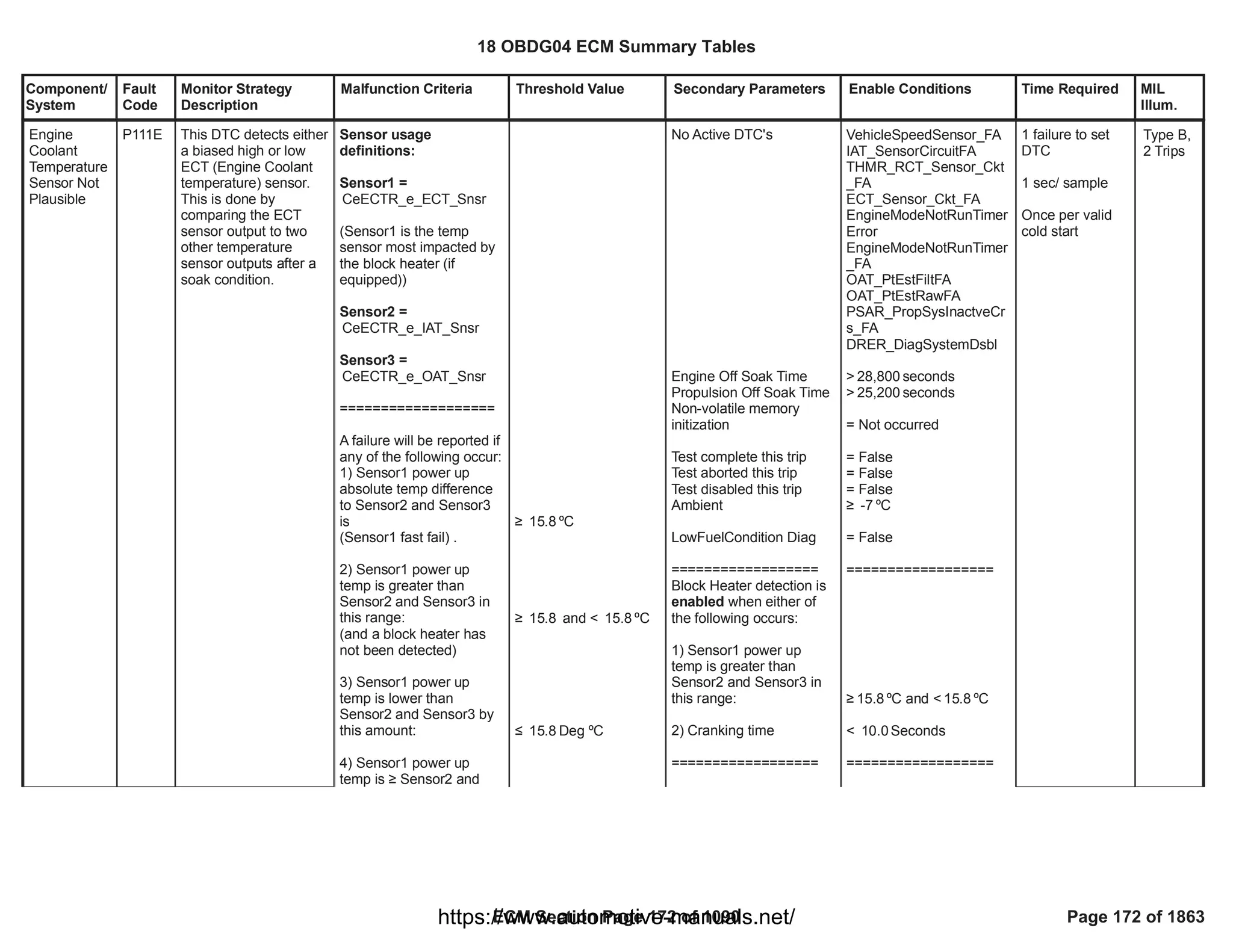
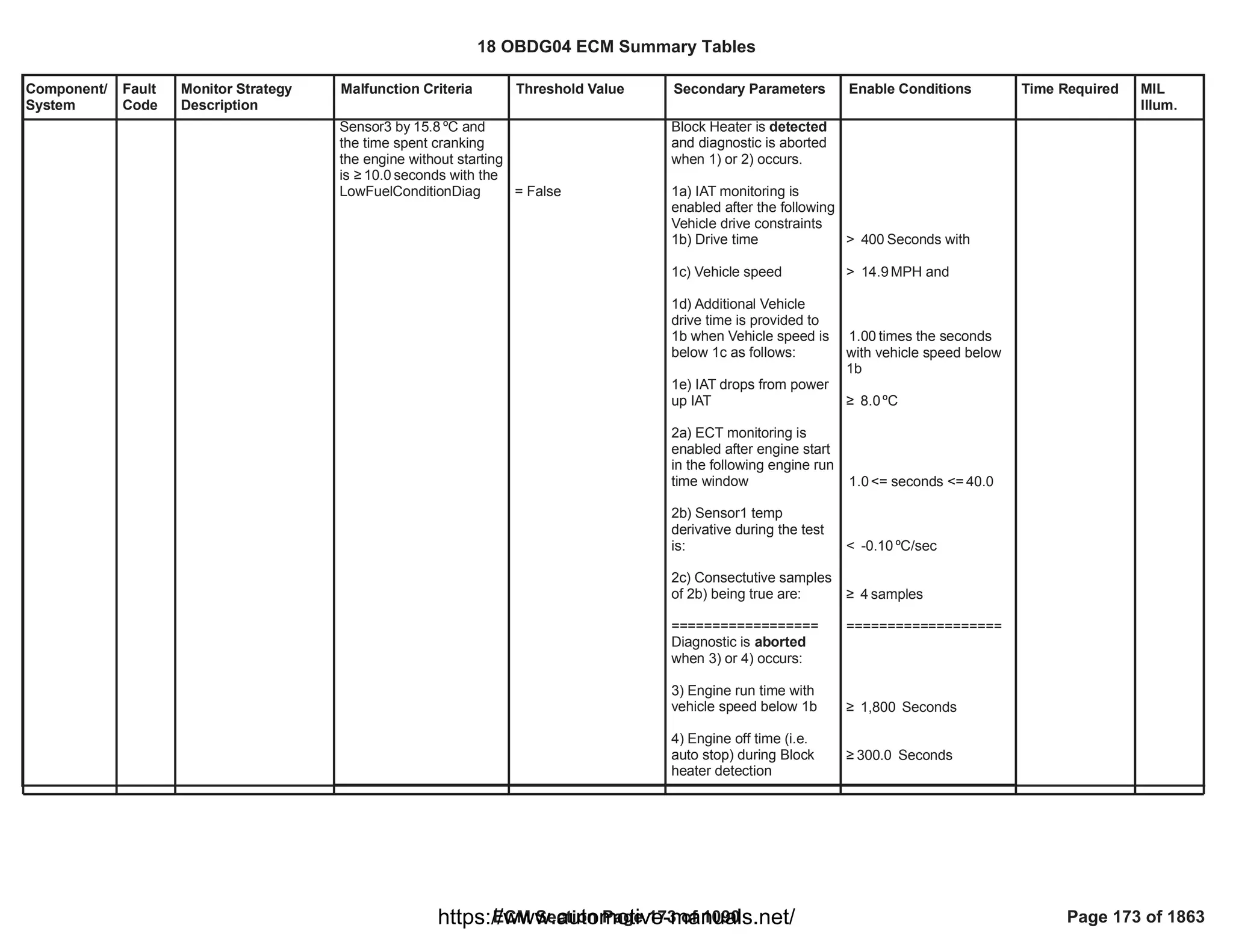
![Component/
System
Fault
Code
Monitor Strategy
Description
Malfunction Criteria Threshold Value Secondary Parameters Enable Conditions Time Required MIL
Illum.
Fuel Pump
Driver Over
Temperature
P1255 To detect if an internal
fuel pump driver over-
temperature condition
exists under normal
operating conditions.
The FTZM ERFS
control may adjust the
PWM slew rate or
frequency as a self-
protection method, but
may not reduce pump
rotational speed or
impact pumping
performance in any
way due to an over-
temperature condition.
Fuel Pump Driver
Temperature
T > 160 degC a) Diagnostic enabled
[KeFABR_b_OvertempDia
gEnbl]
b) Sensor Bus Relay On
c) CAN Sensor Bus
message $3EC_Available
d) Sensor Bus Message
$3EC Temp Signal
Message Counter
Incorrect
[CFMR_b_FTZM_Info7_A
RC_ChkErr]
a) == TRUE
b) == TRUE
c) == TRUE
d) <> TRUE
failures /
5.00
samples
10.00
1 sample / 100
millisec
Type B,
2 Trips
18 OBDG04 ECM Summary Tables
ECM Section Page 174 of 1090 Page 174 of 1863
https://www.automotive-manuals.net/](https://image.slidesharecdn.com/gmcenginefaultcodesdtc1-230327071418-56d3c5bb/75/18-OBDG04-ECM-Summary-Tables-174-2048.jpg)
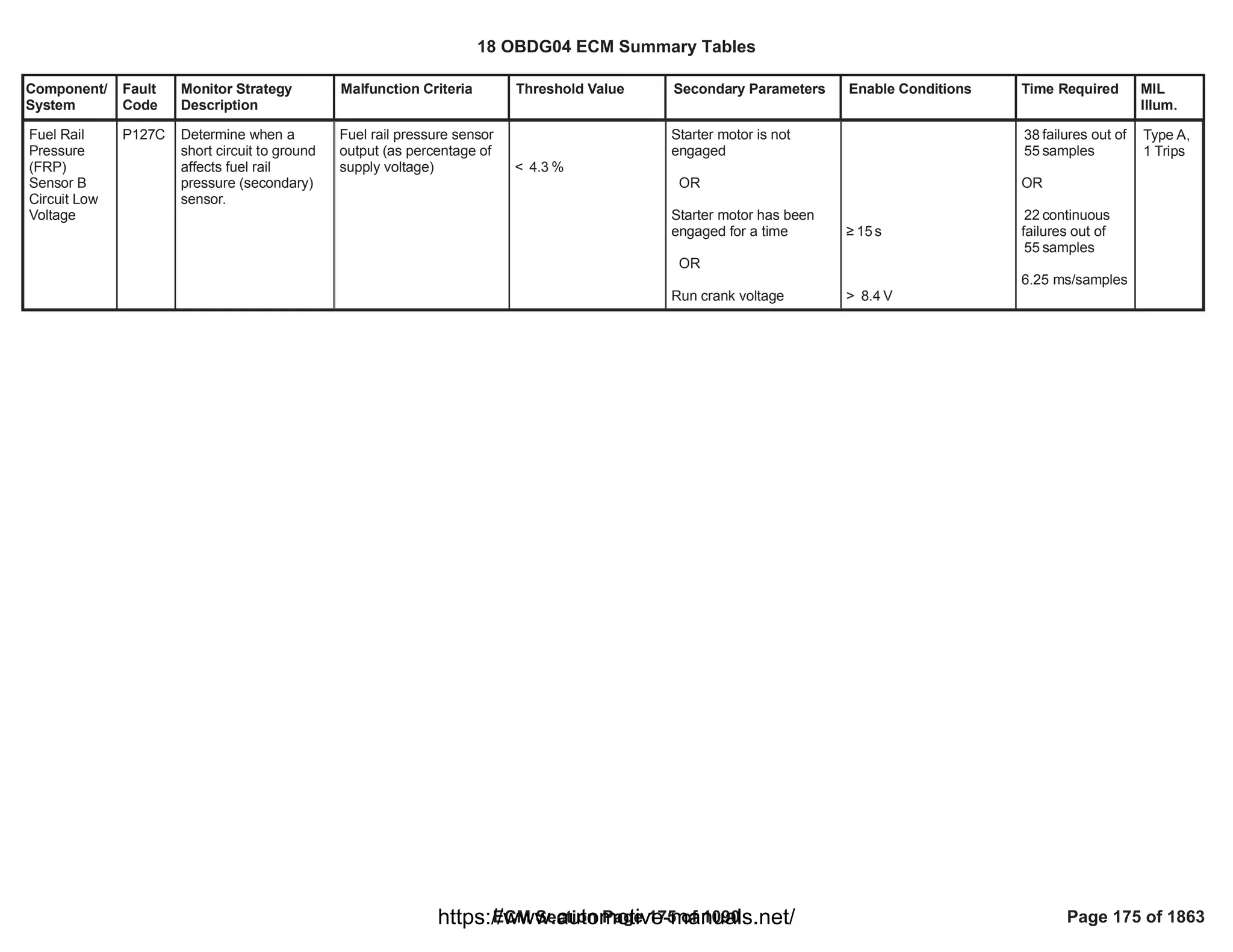

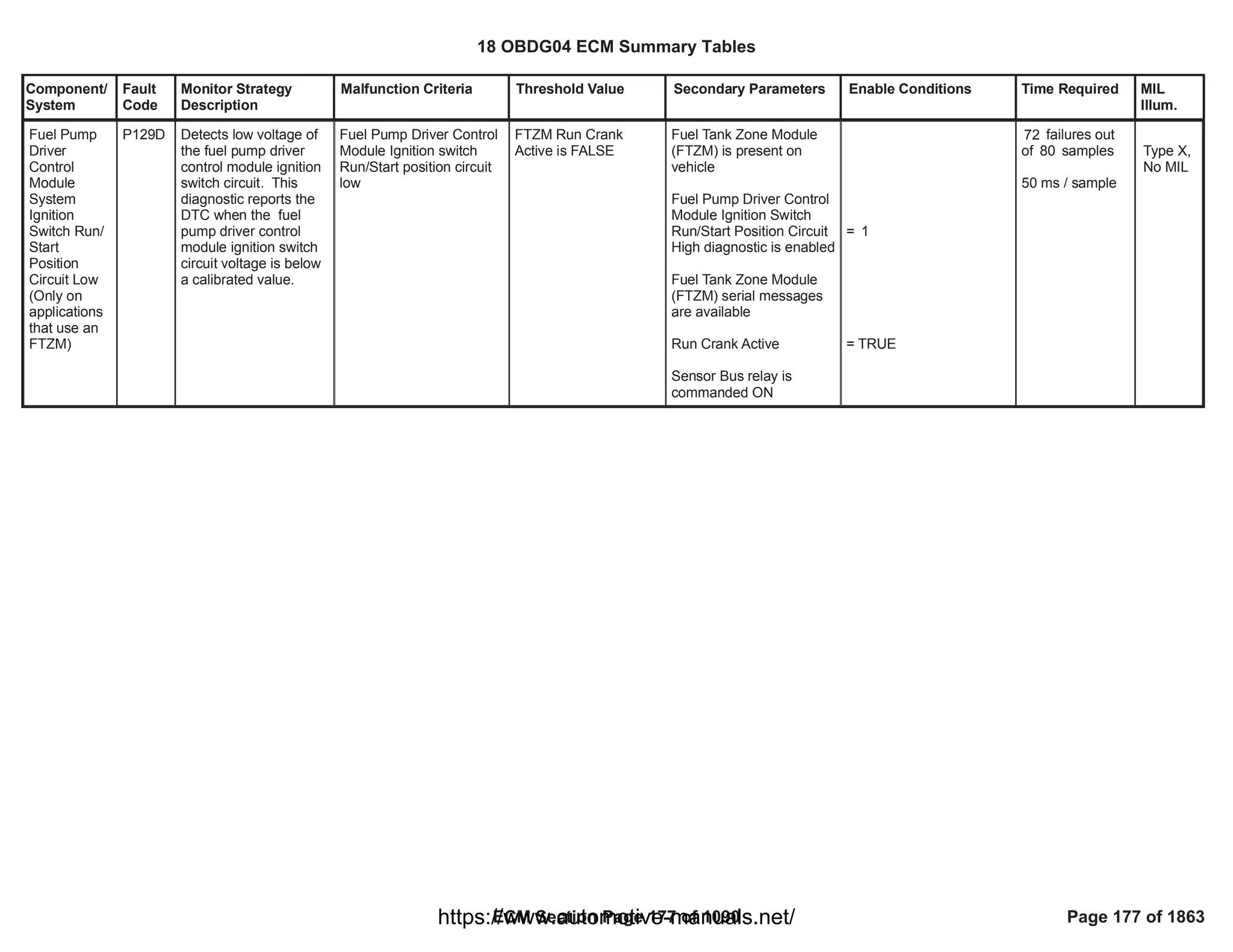
![Component/
System
Fault
Code
Monitor Strategy
Description
Malfunction Criteria Threshold Value Secondary Parameters Enable Conditions Time Required MIL
Illum.
Fuel Pump
Driver
Control
Module Fuel
Pump Speed
Signal
Incorrect
P129F FTZM ERFS control
samples back-
Electromotive Force
[EMF] for zero voltage-
level crossings as a
detection method to
enable closed loop
control brushless
commutation. Back
EMF is an electrical
characteristic of the
inactive phase of the 3-
phase signal wherein
only 2 phases are
active at any moment.
Brushless pump speed
is inferred using rate of
zero-crossings
detection and number
of motor pole-pairs.
Speed is reported to
the ECM as serial data
every 10 millisecs.
Diagnostic software
[FABR ring] calculates
the error between the
commanded,
arbitrated fuel pump
speed [FCBR ring] and
the FTZM sensed fuel
pump speed. The error
is filtered and
evaluated against
calibratable threshold
limits to determine
pass/fail status. Any
failure that exists on
the fuel pump output
circuit (3 phases) will
be manifested in a Fuel
Pump Speed
Sensed Filtered Fuel
Pump Speed Error
> Speed Error Low
Threshold
[Supporting Table]
P129F Threshold Low
OR
< Speed Error High
Threshold
[Supporting Table]
P129F Threshold
High
a) Diagnostic Enabled
FABR Speed Rationality
Diagnostic
b) CAN Sensor Bus
message $0CB_Available
c) FABR Fuel Control
Enable Fault Active
d) Fuel Pmp Speed
Command Alive Rolling
Count and Checksum
Error [CAN Bus B $0CE]
[CFMR_b_FTZM_Cmd1_
ARC_ChkErr]
e) FABR Fuel Pump Ckt
FA
f) FABR Driver OverTemp
FA
g) Run_Crank input
Voltage
h) Sensor Bus Relay On
j) CAN Sensor Bus
message $0CB Data
Fault
[CFMR_b_FTZM_Info8_A
RC_ChkErr]
k) CAN Sensor Bus
message $0CB Comm
Fault
[CFMR_b_FTZM_Info8_U
codeCmFA]
l) Fuel Pmp Spd
Command ARC and
Checksum Comm Fault
Code
[CFMR_b_FTZM_Cmd1_
UcodeCmFA]
m) Timer - FABR Rising
Edge Diagnostic Delay
n) Timer - FABR Falling
Edge Diagn Delay
a) == TRUE
b) == TRUE
c) <> TRUE
d) <> TRUE
e) <> TRUE
f) <> TRUE
g) > volts
11.00
h) == TRUE
j) <> TRUE
k) <> TRUE
l) <> TRUE
m) > seconds
1.00
n) > seconds
1.00
1 sample / 12.5
msec
Type B,
2 Trips
18 OBDG04 ECM Summary Tables
ECM Section Page 178 of 1090 Page 178 of 1863
https://www.automotive-manuals.net/](https://image.slidesharecdn.com/gmcenginefaultcodesdtc1-230327071418-56d3c5bb/75/18-OBDG04-ECM-Summary-Tables-178-2048.jpg)
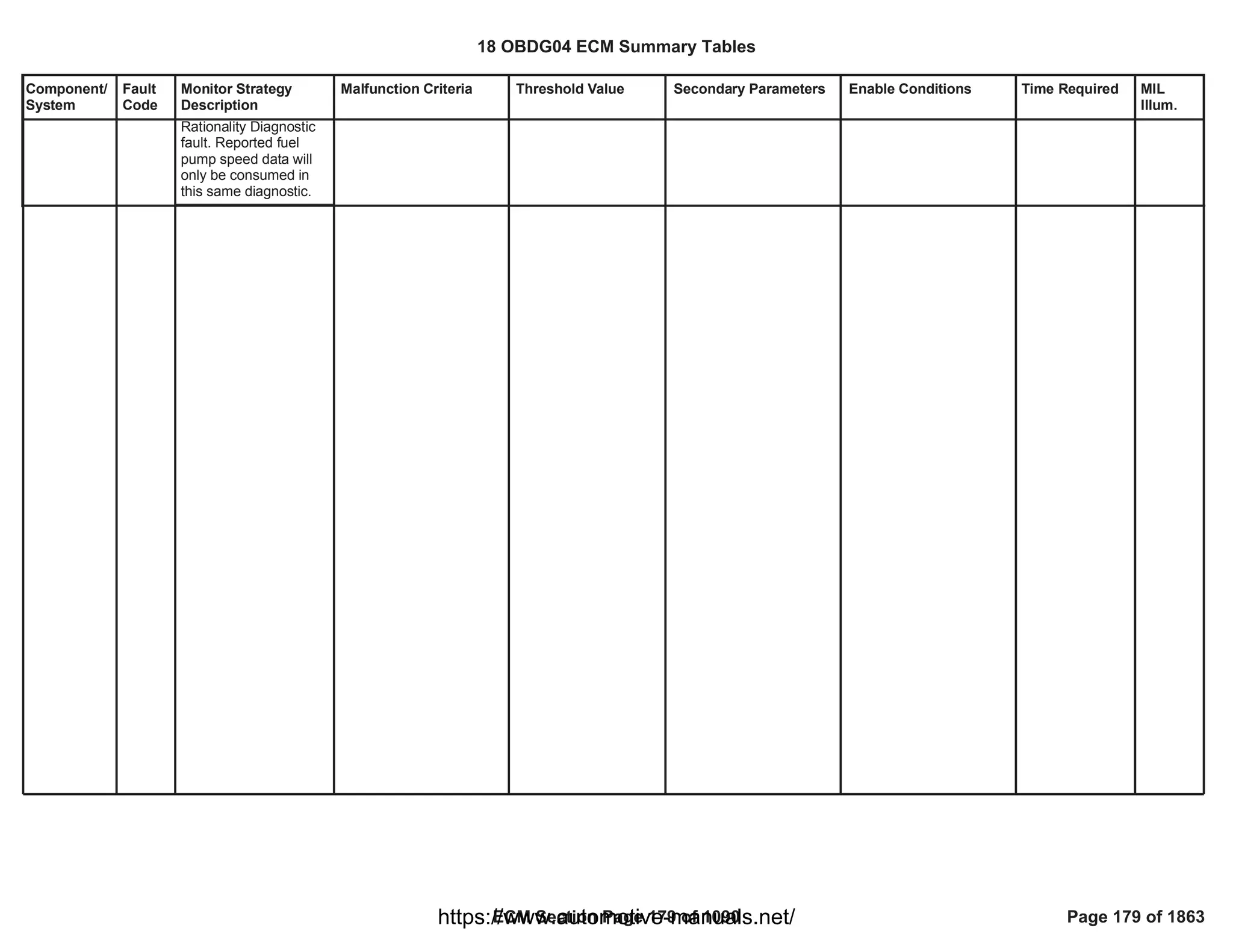
![Component/
System
Fault
Code
Monitor Strategy
Description
Malfunction Criteria Threshold Value Secondary Parameters Enable Conditions Time Required MIL
Illum.
Fuel Pump
Driver
Control
Module
Enable
Circuit
Performance
P12A6 The purpose of the
Fuel Pump Driver
Control Module Enable
Circuit Performance
diagnostic is to detect if
the state of the fuel
control enable circuit is
valid. This is done by
comparing the fuel
control enable circuit
state [high or low]
sensed by the Fuel
Tank Zone Module
device to the
commanded state of
the fuel control enable
signal from the ECM [in
serial data]. When the
sensed state does not
match the commanded
state, the fail counter
increments.
Sensed Fuel Control
Enable circuit state
[Fuel Tank Zone Module
device]
<> Fuel Control Enable
Active command
[serial data]
a) Diagnostic enabled
[KeFABR_b_FuelCntrlEnb
lDiagEnbl]
b) Sensor Bus message
$0CC Fuel Pump
Command Message
Signal Counter Incorrect
[CFMR_b_FTZM_Info2_A
RC_ChkErr]
c) CAN Sensor Bus
message $0CC_Available
d) Sensor Bus Relay On
e) Timer
[FABR_t_RunCrankActive
]
a) == TRUE
b) <> TRUE
c) == TRUE
d) == TRUE
e) >= seconds
0.51
failures /
40.00
samples
80.00
1 sample / 12.5
millisec
Type A,
1 Trips
18 OBDG04 ECM Summary Tables
ECM Section Page 180 of 1090 Page 180 of 1863
https://www.automotive-manuals.net/](https://image.slidesharecdn.com/gmcenginefaultcodesdtc1-230327071418-56d3c5bb/75/18-OBDG04-ECM-Summary-Tables-180-2048.jpg)
![Component/
System
Fault
Code
Monitor Strategy
Description
Malfunction Criteria Threshold Value Secondary Parameters Enable Conditions Time Required MIL
Illum.
FPPM Control Status
Alive Rolling Count
<> ECM Control Status
Alive Rolling Count
( Fu Pmp Pwr Mod
smart device reports
Faulted, Not Faulted or
Indeterminate test
state)
a) Chassis Fuel Pres Sys
Type configuration
selection
b) Diagnostic Enabled
c) FPPM Diagnostic
serial data received
d) Run_Crank Ignition
Switch Position Circuit
Voltage
a) == FCBR ECM FPPM
Sys
b) == TRUE
c) == TRUE
d) > Volts
0.00
failures /
0
samples
0
1 sample / 12.5
millisec
Fuel Pump
Control
Status
Signal
Message
Counter
Incorrect
[FPPM
applications
only]
P12A8 To detect if the control
status message
transmitted as serial
data from the driver
control module is valid.
The "rolling count
check" value is created
by adding an appended
hexadecimal
calculation to each
control command
value. The
corresponding "check"
value is transmitted to
the FPPM as well as
the actual command.
At the FPPM, the
received command
value is used to create
an expected "rolling
count" value using the
same calculation
method as the ECM.
The expected "rolling
count" value calculated
at the receiving power
module ( smart device)
is compared to the
transmitted "rolling
count" value. If these
do not match, a fault
condition is reported
forward to the ECM
where X/Y diagnostic
counting is performed.
Type B,
2 Trips
FPPM Power
Consumption Alive Rolling
Count
<> ECM Power
Consumption Alive
Rolling Count
( Fu Pmp Pwr Mod
smart device reports
Faulted, Not Faulted or
Indeterminate test
state)
a) Chassis Fuel Pres Sys
Type configuration
selection
b) Diagnostic Enabled
c) FPPM Diagnostic
serial data received
d) Run_Crank Ignition
Switch Position Circuit
Voltage
a) == FCBR ECM FPPM
Sys
b) == TRUE
c) == TRUE
d) > Volts
0.00
failures /
0
samples
0
1 sample / 12.5
millisec
FPPM Driver Status Alive
Rolling Count
<> ECM Driver Status
Alive Rolling Count
( Fu Pmp Pwr Mod
smart device reports
Faulted, Not Faulted or
Indeterminate test
state)
a) Chassis Fuel Pres Sys
Type configuration
selection
b) Diagnostic Enabled
c) FPPM Diagnostic
serial data received
d) Run_Crank Ignition
Switch Position Circuit
Voltage
a) == FCBR ECM FPPM
Sys
b) == TRUE
c) == TRUE
d) > Volts
0.00
failures /
0
samples
0
1 sample / 12.5
millisec
FPPM Hardware Status
Alive Rolling Count
<> ECM Hardware
Status Alive Rolling
Count
( Fu Pmp Pwr Mod
smart device reports
Faulted, Not Faulted or
Indeterminate test
state)
a) Chassis Fuel Pres Sys
Type configuration
selection
b) Diagnostic Enabled
c) FPPM Diagnostic
serial data received
d) Run_Crank Ignition
Switch Position Circuit
Voltage
a) == FCBR ECM FPPM
Sys
b) == TRUE
c) == TRUE
d) > Volts
0.00
failures /
0
samples
0
1 sample / 12.5
millisec
18 OBDG04 ECM Summary Tables
ECM Section Page 181 of 1090 Page 181 of 1863
https://www.automotive-manuals.net/](https://image.slidesharecdn.com/gmcenginefaultcodesdtc1-230327071418-56d3c5bb/75/18-OBDG04-ECM-Summary-Tables-181-2048.jpg)
![Component/
System
Fault
Code
Monitor Strategy
Description
Malfunction Criteria Threshold Value Secondary Parameters Enable Conditions Time Required MIL
Illum.
EGR Slow
Response -
Increasing
Flow (OBDII
market only)
P140B This monitor (in
increasing flow
direction) detects
failures in the air
system such to not
fulfilll the request of
EGR flow in the intake
manifold during
transient conditions. It
works only in closed
loop EGR control zone.
This monitor is used to
detect any malfunction
in the EGR system that
leads to slow down the
air control causing the
vehicle's emissions to
exceed OBDII limits.
The aim of the EGR
flow slow response
monitor is to detect
small leakages in the
pipe after the
compressor or in the
intake/exhaust
manifold. This monitor
could also detect slow
responding EGR
valves, or skewed MAF
sensor. Slow
responding throttle and
VGT vanes could also
affect the EGR flow
response time.
Error difference (absolute
value) between the
desired EGR rate and the
actual EGR rate during
transient air control
conditions. The error is
averaged over a calibrate-
able cumulative transient
time.
>
P140B: Increasing
EGR slow response
threshold
[%]
Calibration on diagnostic
enabling
Engine Running
Cranking ignition in range
PT Relay voltage in range
Air Control is Active (air
control in closed loop)
Air control active condition
lasts for a time
Desired EGR rate
No active transition from a
combustion mode to
another one
OBD Coolant Enable
Criteria
Throttle measured
position
Outside air temperature
P140B, P140C: EGR
slow response enabling
==TRUE
==TRUE
Battery voltage > 11.00
[V]
Powertrain relay voltage >
[V]
11.00
Refer to "Air Control
Active" Free Form
> [s]
0.25
> 0 [%]
==TRUE
==TRUE
> [%]
90.00
> [°C]
-7.00
Test is evaluated
after the
enabling
conditions are
satisfied for a
number of
samples
>= 200.00
sampling time is
25ms
Type B,
2 Trips
18 OBDG04 ECM Summary Tables
ECM Section Page 182 of 1090 Page 182 of 1863
https://www.automotive-manuals.net/](https://image.slidesharecdn.com/gmcenginefaultcodesdtc1-230327071418-56d3c5bb/75/18-OBDG04-ECM-Summary-Tables-182-2048.jpg)
![Component/
System
Fault
Code
Monitor Strategy
Description
Malfunction Criteria Threshold Value Secondary Parameters Enable Conditions Time Required MIL
Illum.
Ambient air pressure
Engine speed in range
Desired fuel quantity in
range
Exhaust manifold
pressure in range
Desired air request is
steady state:
AirReq-AirReqOld
Air control tracking error
(air setpoint-MAF
measure)
EGR valve position
OR
it is above that threshold
for a time
Exhaust manifold
pressure is valid
Nominal EGR valve total
> [kPa]
74.80
> [rpm]
1,500.00
AND
< [rpm]
3,500.00
> [mm^3]
10.00
AND
< [mm^3]
50.00
> [kPa]
100.00
AND
< [kPa]
350.00
> [mg/s]
-75.00
AND
< [mg/s]
-10.00
< 0 [mg]
<= [%]
100.00
>= [s]
0.00
EXM_ExhMnfdPresNotVl
d
==FALSE
18 OBDG04 ECM Summary Tables
ECM Section Page 183 of 1090 Page 183 of 1863
https://www.automotive-manuals.net/](https://image.slidesharecdn.com/gmcenginefaultcodesdtc1-230327071418-56d3c5bb/75/18-OBDG04-ECM-Summary-Tables-183-2048.jpg)
![Component/
System
Fault
Code
Monitor Strategy
Description
Malfunction Criteria Threshold Value Secondary Parameters Enable Conditions Time Required MIL
Illum.
EGR Slow
Response -
Decreasing
Flow (OBDII
market only)
P140C This monitor (in
decreasing flow
direction) detects
failures in the air
system such to not
fulfilll the request of
EGR flow in the intake
manifold during
transient conditions. It
works only in closed
loop EGR control zone.
This monitor is used to
detect any malfunction
in the EGR system that
lead to slow down the
air control causing the
vehicle's emissions to
exceed OBDII limits.
The aim of the EGR
flow slow response
monitor is to detect
small obstructions in
the exhaust pipe. This
monitor could also
detect slow responding
EGR valves, or skewed
MAF sensor. Slow
responding throttle and
VGT vanes could also
affect the EGR flow
response time.
Error difference (absolute
value) between the
desired EGR rate and the
actual EGR rate during
transient air control
conditions. The error is
averaged over a calibrate-
able cumulative transient
time.
>
P140C: Decreasing
EGR slow response
threshold
[%]
Calibration on diagnostic
enabling
Engine Running
Cranking ignition in range
PT Relay voltage in range
Air Control is Active (air
control in closed loop)
Air control active condition
lasts for a time
Desired EGR rate
No active transition from a
combustion mode to
another one
OBD Coolant Enable
Criteria
Throttle measured
position
Outside air temperature
P140B, P140C: EGR
slow response enabling
==TRUE
==TRUE
Battery voltage > 11.00
[V]
Powertrain relay voltage >
[V]
11.00
Refer to "Air Control
Active" Free Form
> [s]
0.25
> 0 [%]
==TRUE
==TRUE
> [%]
90.00
> [°C]
-7.00
Test is evaluated
after the
enabling
conditions are
satisfied for a
number of
samples
>= 200.00
sampling time is
25ms
Type B,
2 Trips
18 OBDG04 ECM Summary Tables
ECM Section Page 185 of 1090 Page 185 of 1863
https://www.automotive-manuals.net/](https://image.slidesharecdn.com/gmcenginefaultcodesdtc1-230327071418-56d3c5bb/75/18-OBDG04-ECM-Summary-Tables-185-2048.jpg)
![Component/
System
Fault
Code
Monitor Strategy
Description
Malfunction Criteria Threshold Value Secondary Parameters Enable Conditions Time Required MIL
Illum.
Ambient air pressure
Engine speed in range
Desired fuel quantity in
range
Exhaust manifold
pressure in range
Desired air request is
steady state:
AirReq-AirReqOld
Air control tracking error
(air setpoint-MAF
measure)
Exhaust manifold
pressure is valid
Nominal valve total flow is
valid
> [kPa]
74.80
> [rpm]
1,500.00
AND
< [rpm]
3,500.00
> [mm^3]
7.50
AND
< [mm^3]
50.00
> [kPa]
100.00
AND
< [kPa]
350.00
> [mg/s]
10.00
AND
< [mg/s]
75.00
> 0 [mg]
EXM_ExhMnfdPresNotVl
d
==FALSE
EGR_VlvTotFlowNomNot
Vld
==FALSE
18 OBDG04 ECM Summary Tables
ECM Section Page 186 of 1090 Page 186 of 1863
https://www.automotive-manuals.net/](https://image.slidesharecdn.com/gmcenginefaultcodesdtc1-230327071418-56d3c5bb/75/18-OBDG04-ECM-Summary-Tables-186-2048.jpg)
![Component/
System
Fault
Code
Monitor Strategy
Description
Malfunction Criteria Threshold Value Secondary Parameters Enable Conditions Time Required MIL
Illum.
Reference Voltage 0
Period Error Maximum
[Measured Ref V Period -
Commanded Ref V
Period]
> millisec
25.00 a] CAN serial data
available [$2D7]
b] Calibration - Reference
Voltage Command Source
c] Timer - Reference
Voltage Pulse Width
Available Synchronization
d] Timer - Reference
Voltage Period Available
Delay
e] Diagnostic System
Disabled
f] FTZM Serial Data Info4
Rolling Counter Check
Error
g] Reference Voltage
Performance 0 Diagnostic
Enabled
a] == True
b] == ECM
c] > sec
1.25
d] > sec
0.75
e] <> True
f] <> True
g] == TRUE
250 ms / sample
Fuel Level
Sensor A
Reference
Feedback
Range/
Performance
[For use on
vehicles with
FTZM]
P1434 This DTC will detect a
fault in Primary fuel
tank level sensor 5V
reference by comparing
DEC ECU commanded
signal period and pulse
width values against
measured period and
pulse width reported by
the smart device
Type B,
2 Trips
Reference Voltage 0
Pulse Width Error
Maximum
[Measured Ref V PW -
Commanded Ref V PW]
> millisec
1.50 a] CAN serial data
available [$2D7]
b] Calibration - Reference
Voltage Command Source
c] Timer - Reference
Voltage Pulse Width
Available Synchronization
d] Timer - Reference
Voltage Period Available
Delay
e] Diagnostic System
Disabled
a] == True
b] == ECM
c] > sec
1.25
d] > sec
0.75
e] <> True
250 ms / sample
Failures /
16
Samples
20
18 OBDG04 ECM Summary Tables
ECM Section Page 187 of 1090 Page 187 of 1863
https://www.automotive-manuals.net/](https://image.slidesharecdn.com/gmcenginefaultcodesdtc1-230327071418-56d3c5bb/75/18-OBDG04-ECM-Summary-Tables-187-2048.jpg)
![Component/
System
Fault
Code
Monitor Strategy
Description
Malfunction Criteria Threshold Value Secondary Parameters Enable Conditions Time Required MIL
Illum.
f] FTZM Serial Data Info4
Rolling Counter Check
Error
g] Reference Voltage
Performance 0 Diagnostic
Enabled
f] <> True
g] == TRUE
18 OBDG04 ECM Summary Tables
ECM Section Page 188 of 1090 Page 188 of 1863
https://www.automotive-manuals.net/](https://image.slidesharecdn.com/gmcenginefaultcodesdtc1-230327071418-56d3c5bb/75/18-OBDG04-ECM-Summary-Tables-188-2048.jpg)
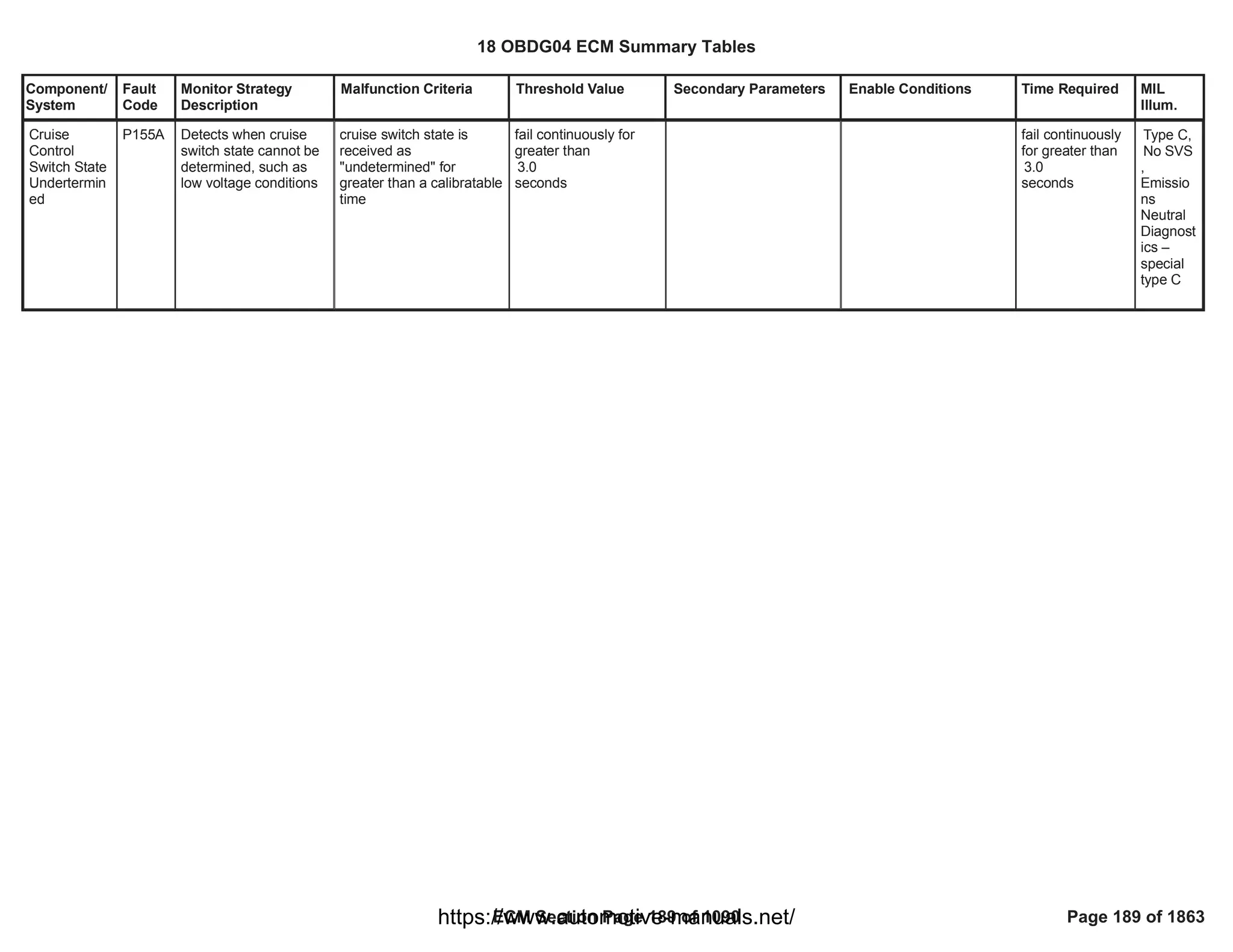
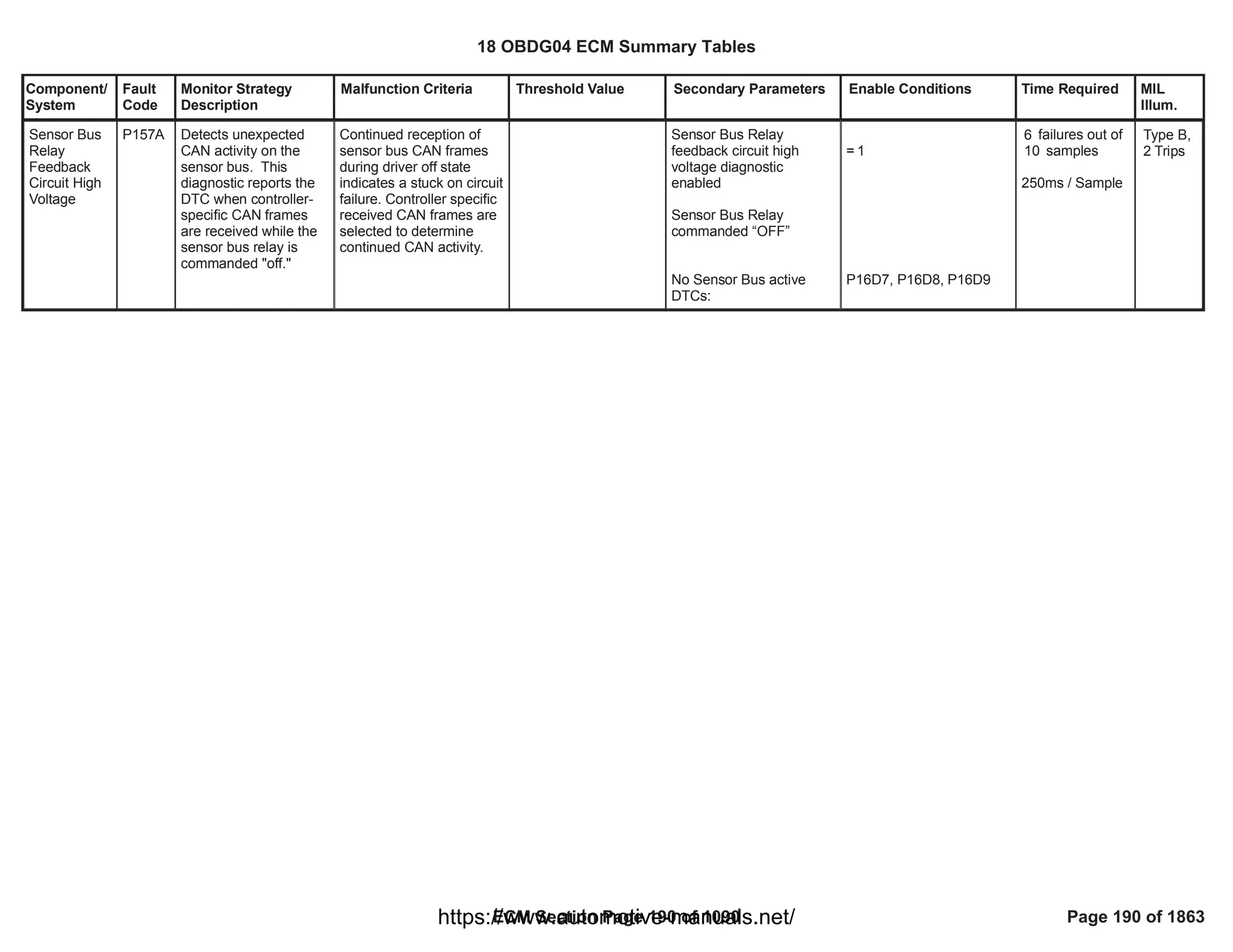
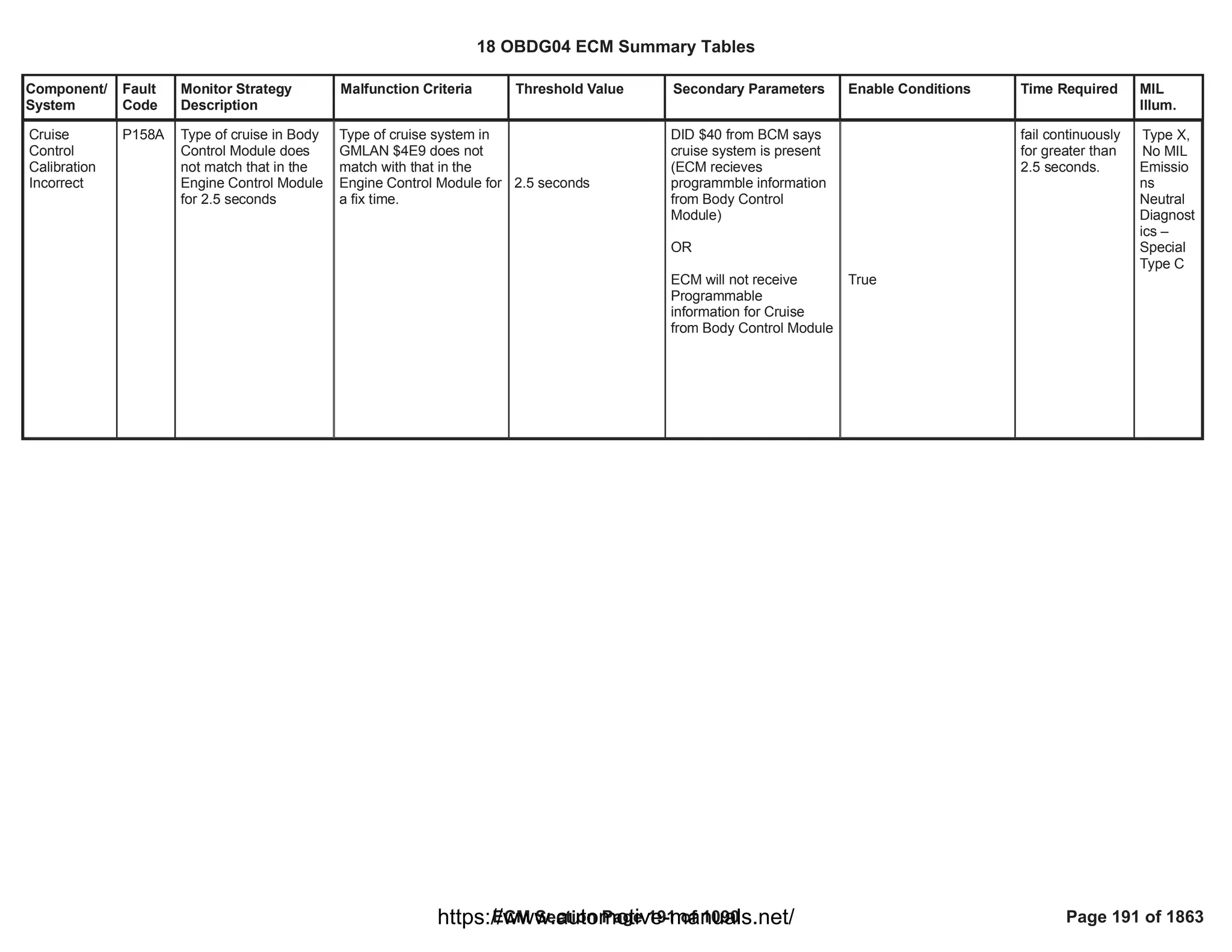
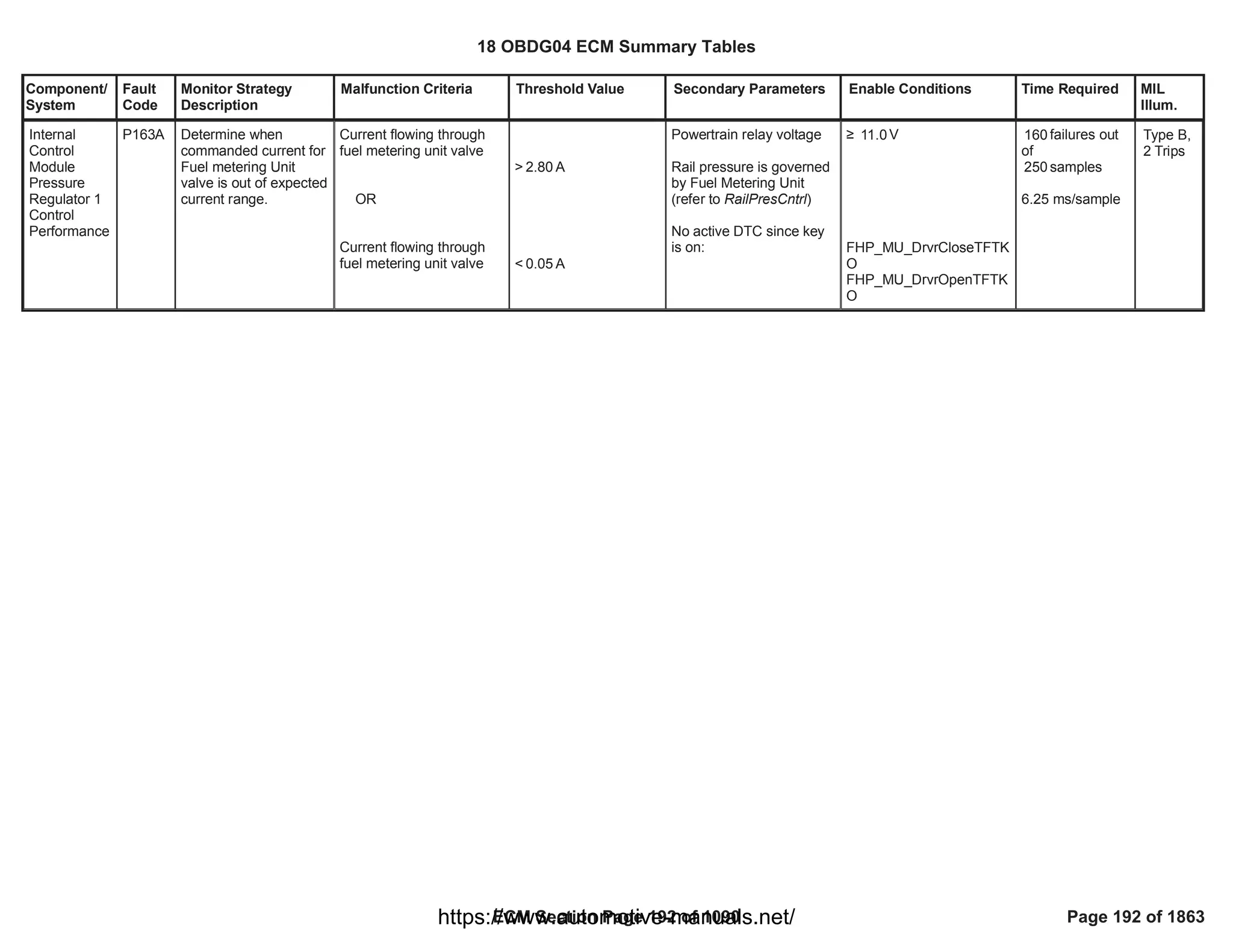

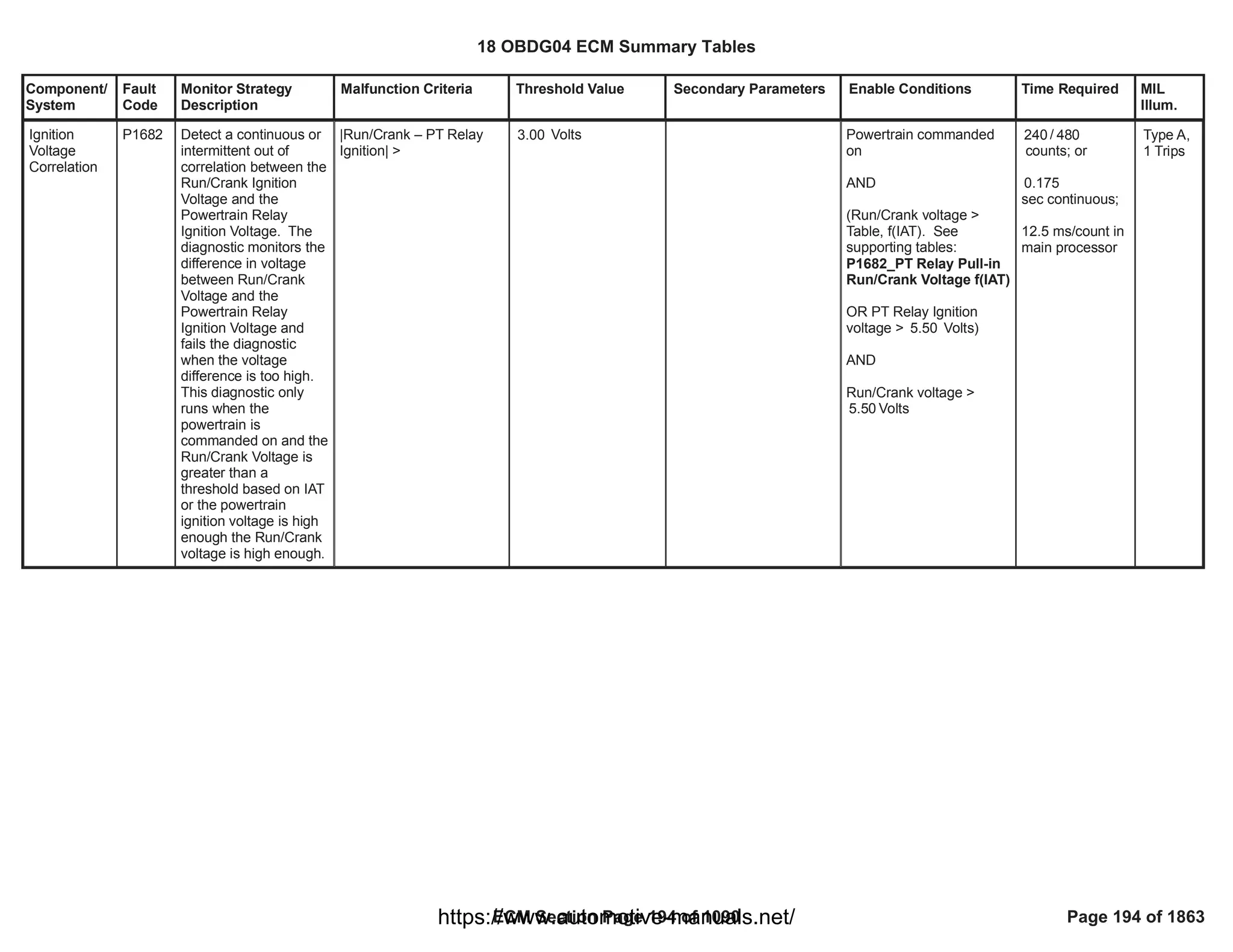
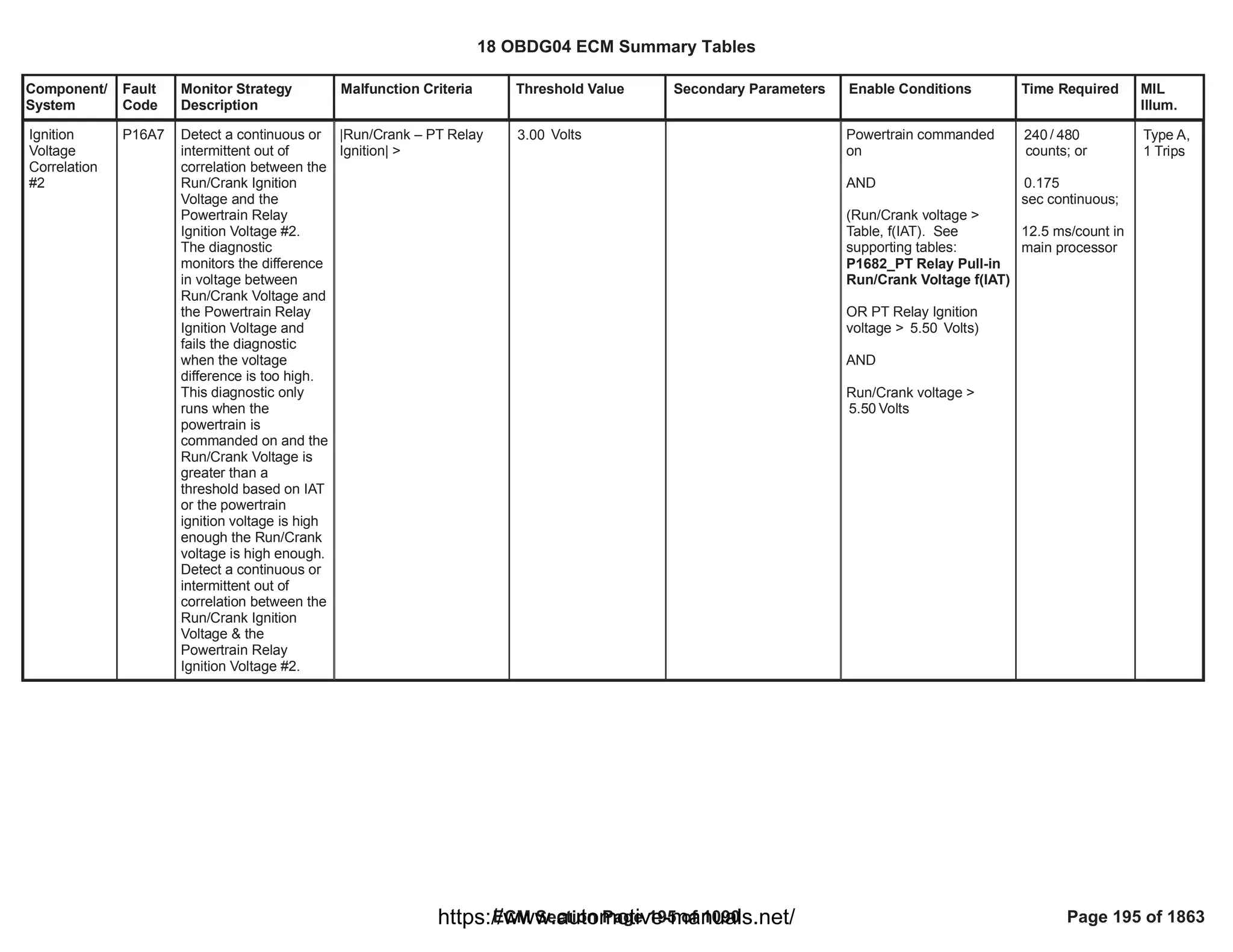
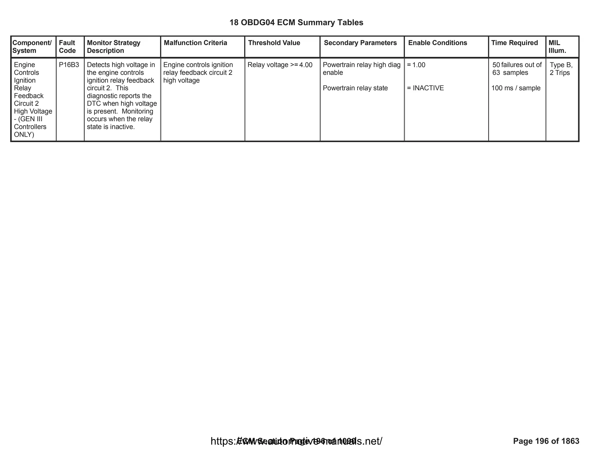
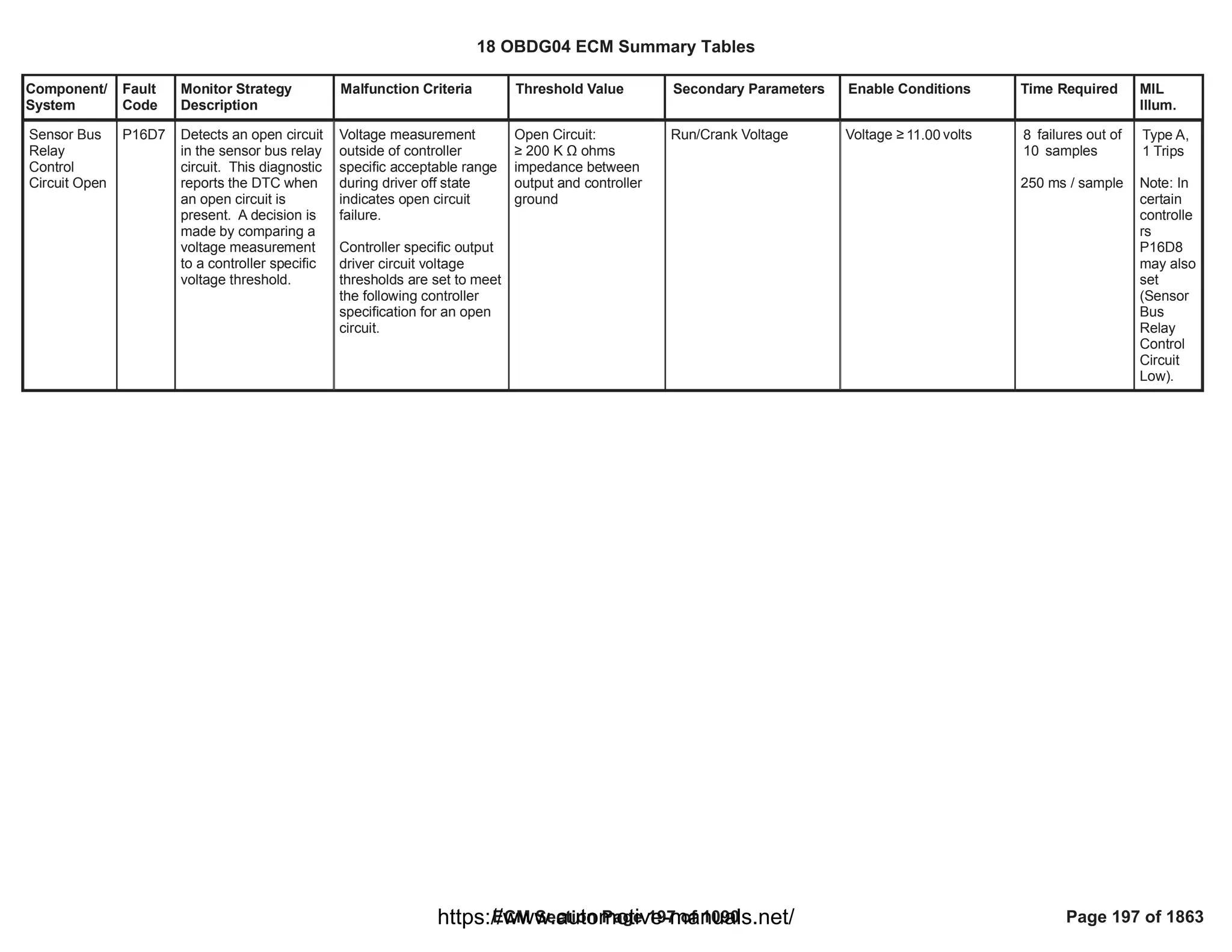
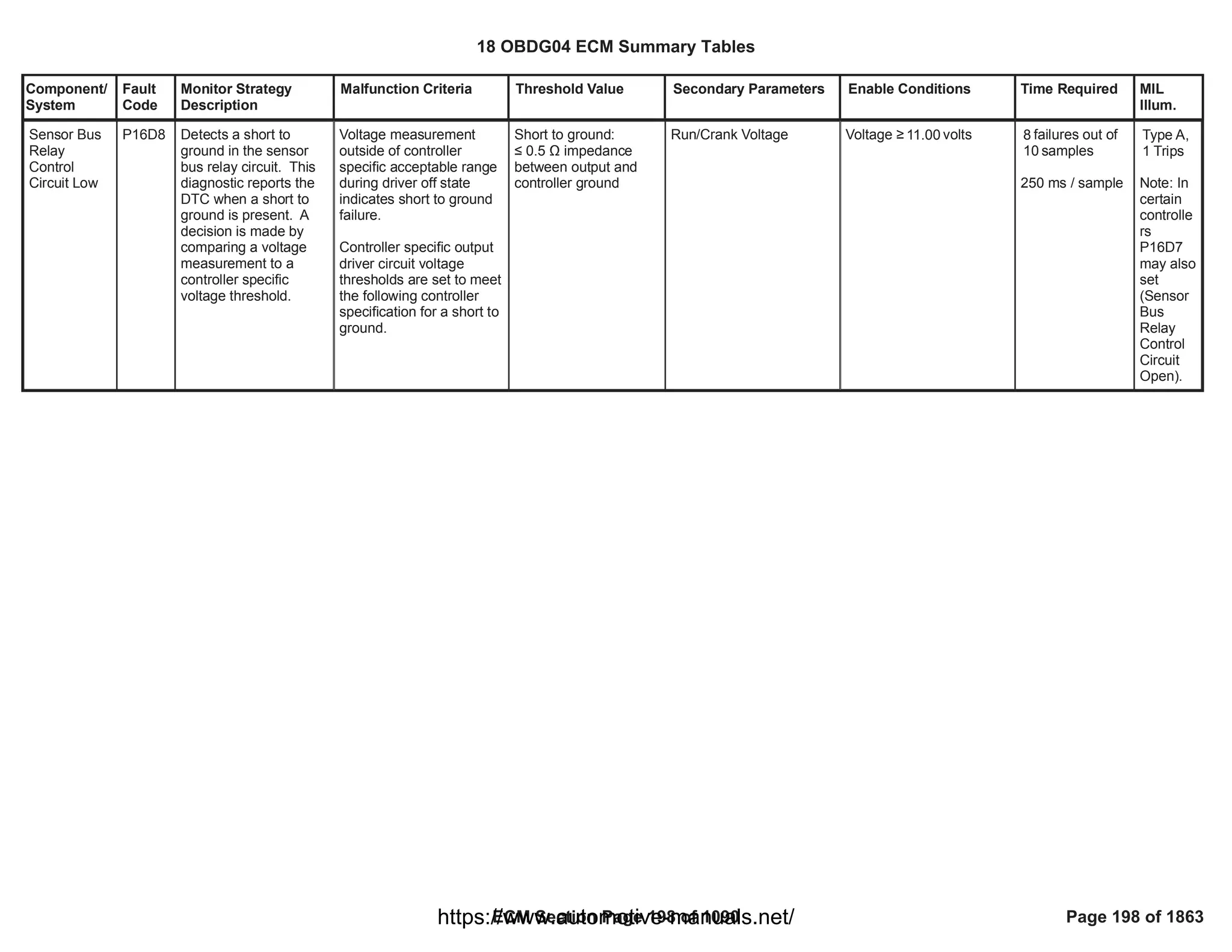
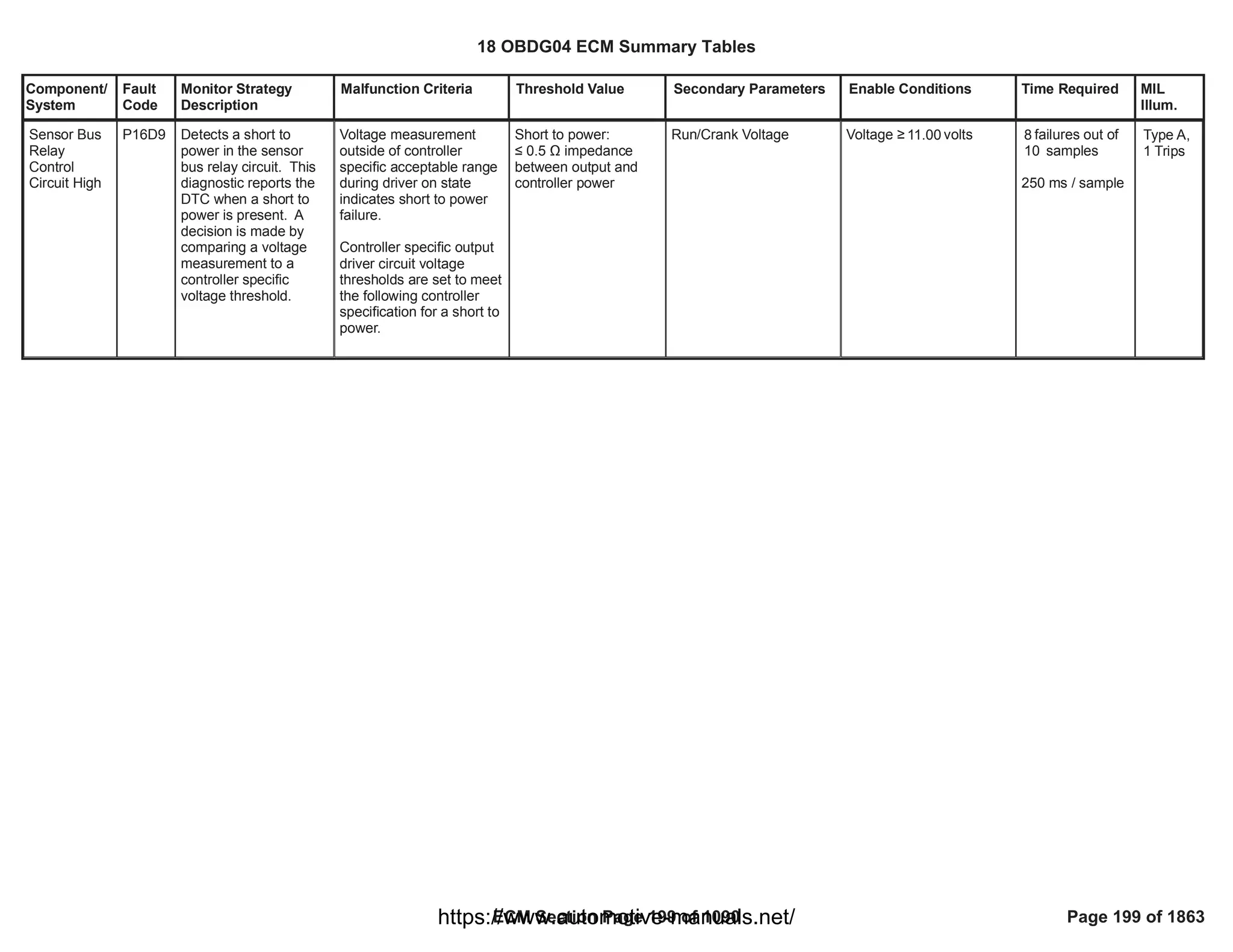
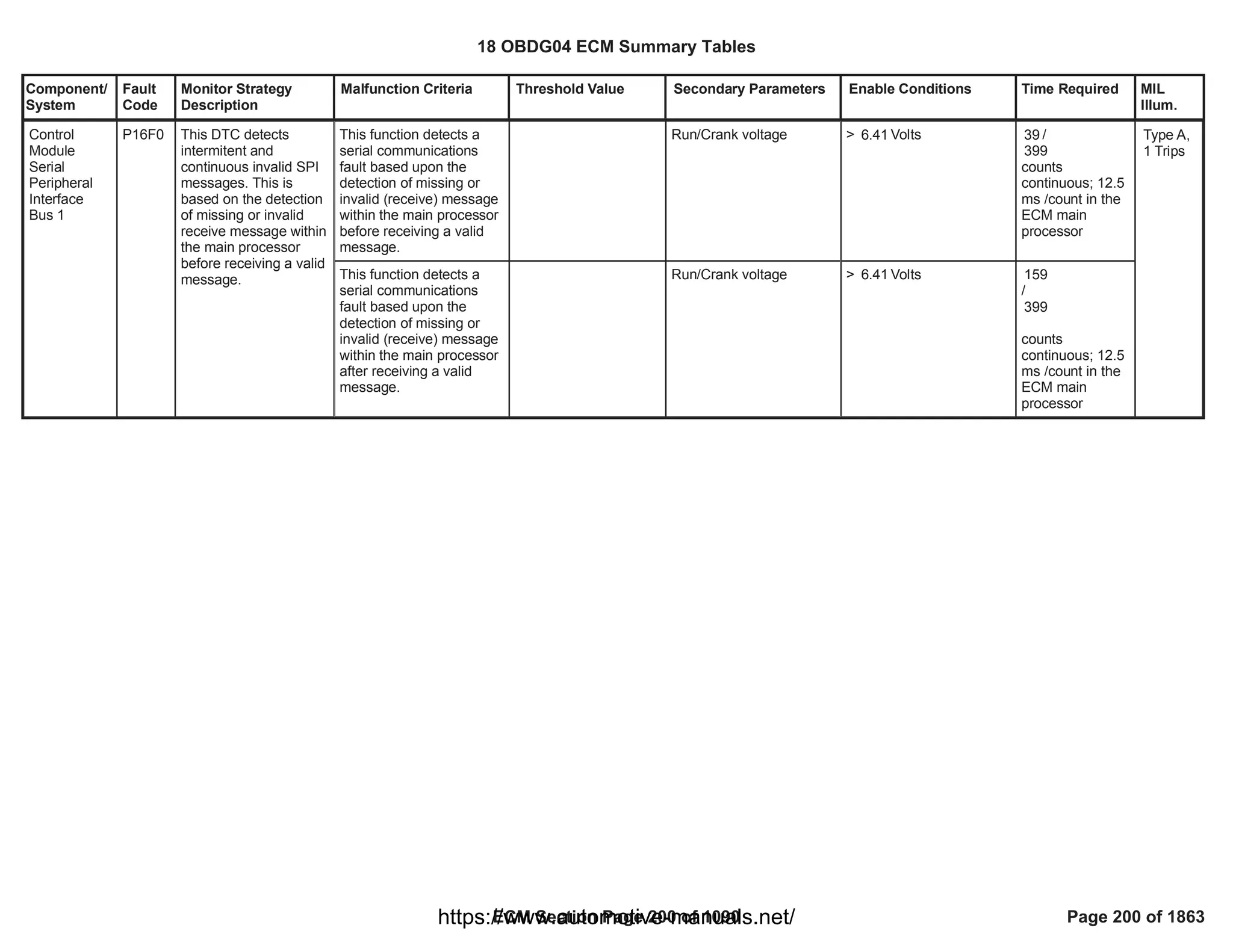
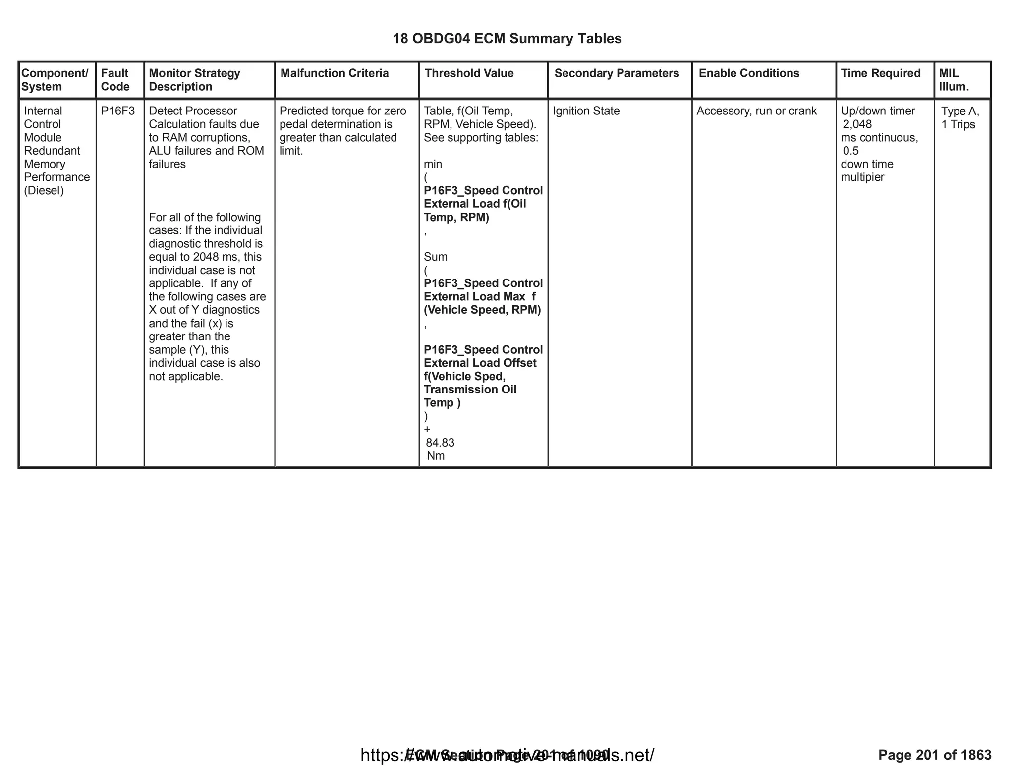

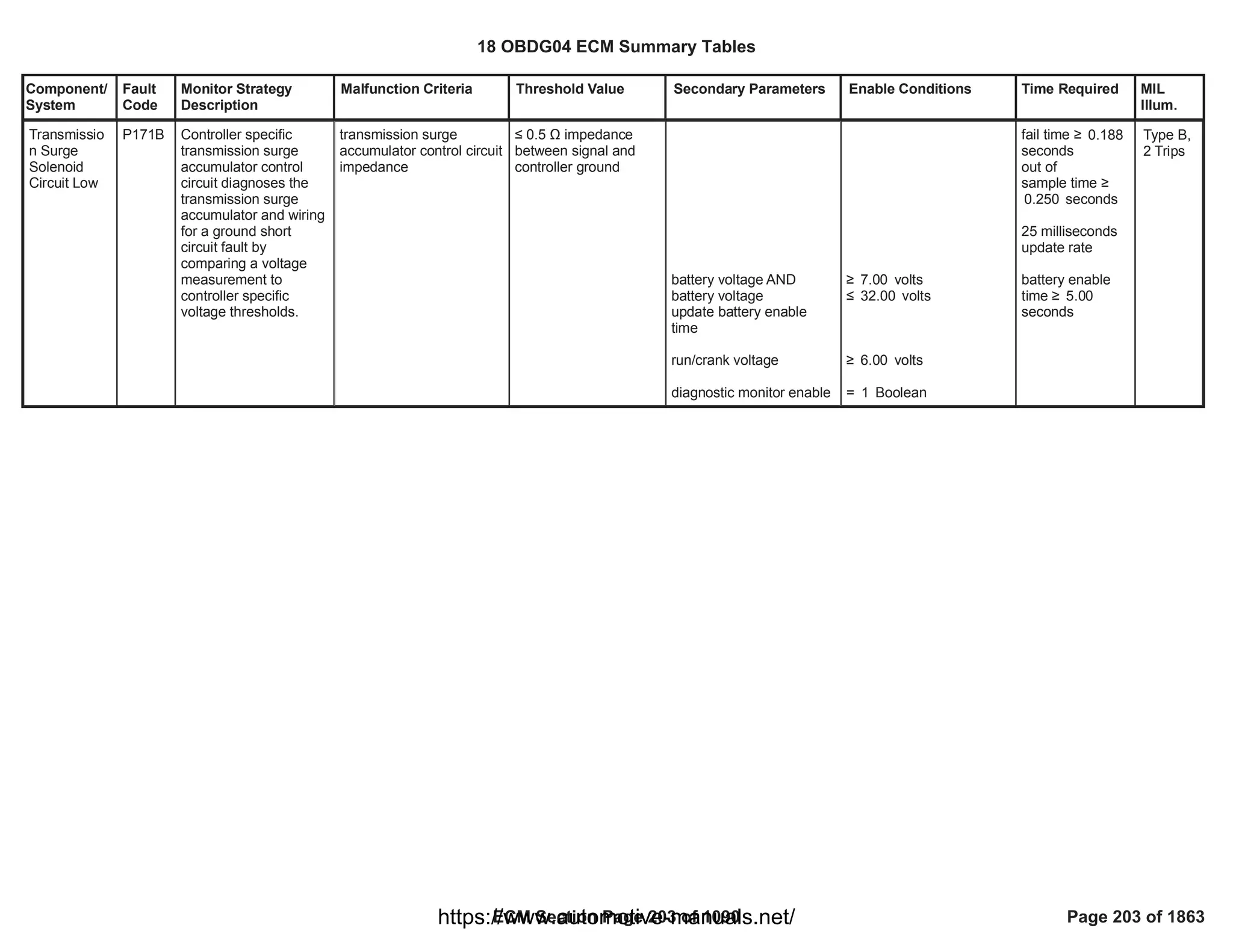
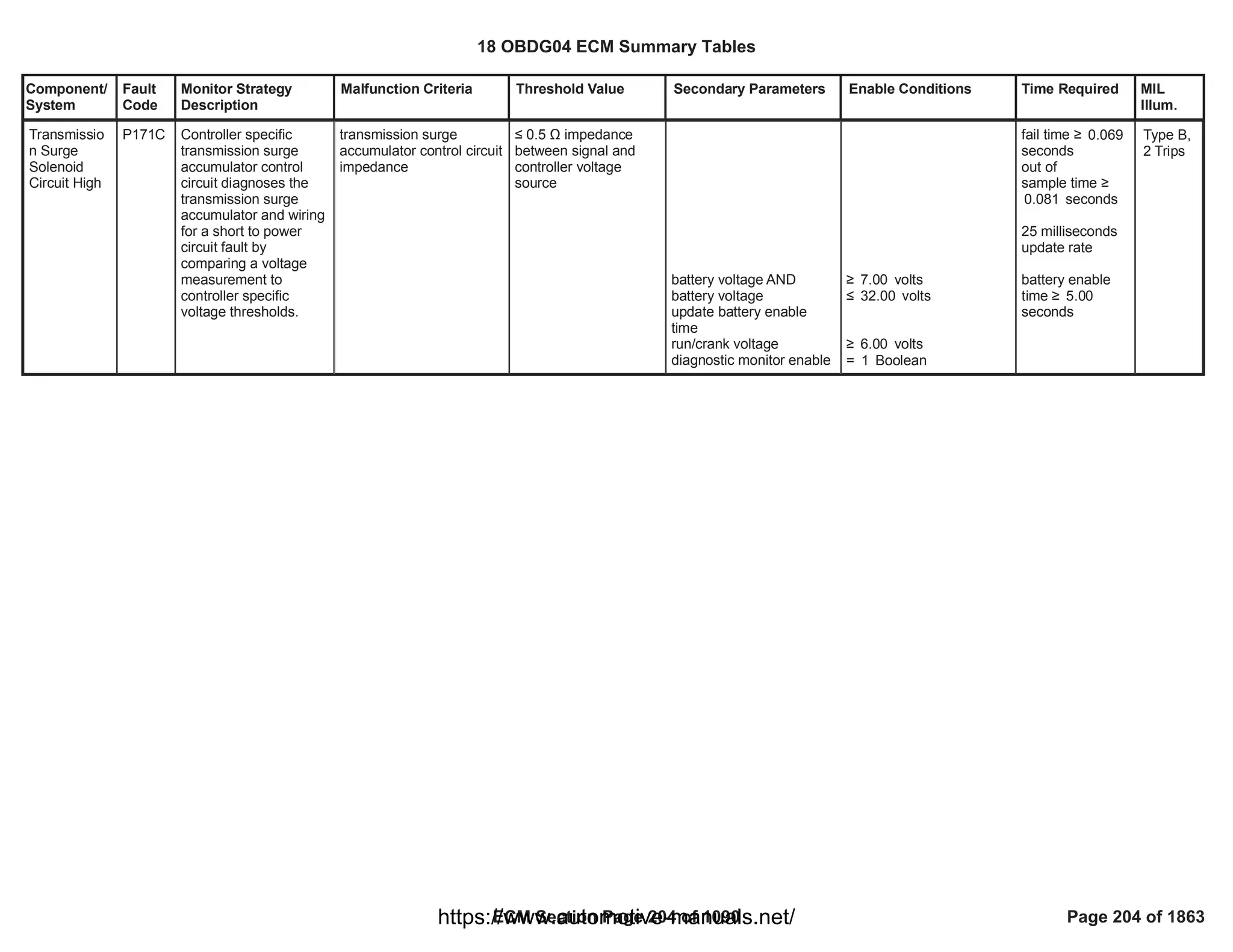
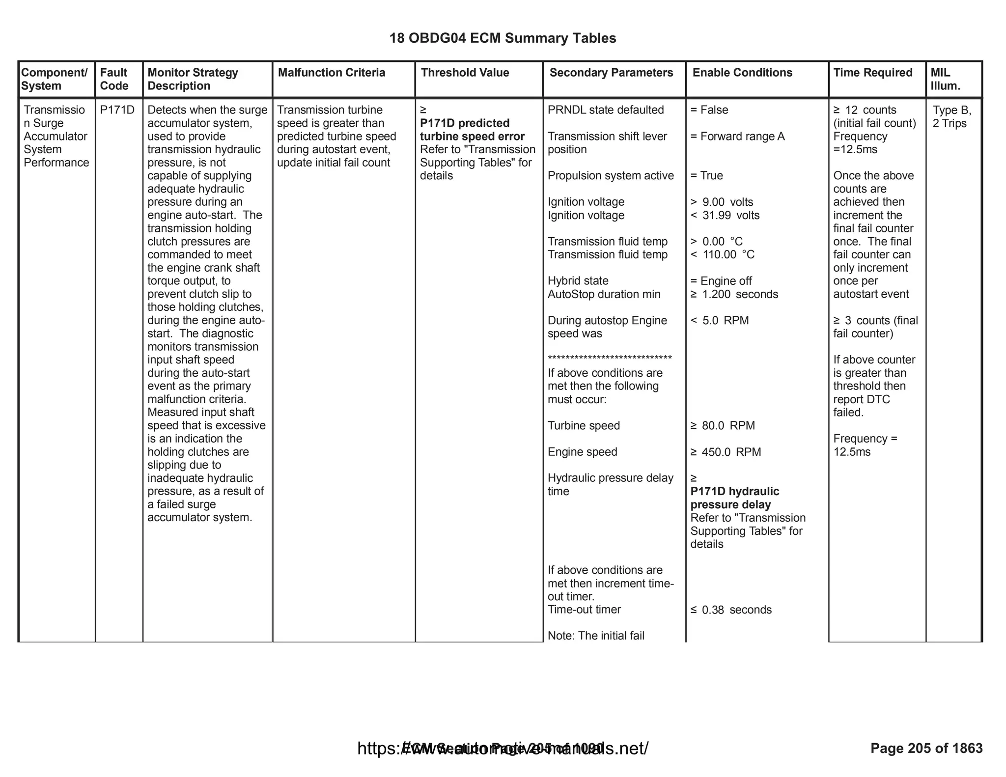
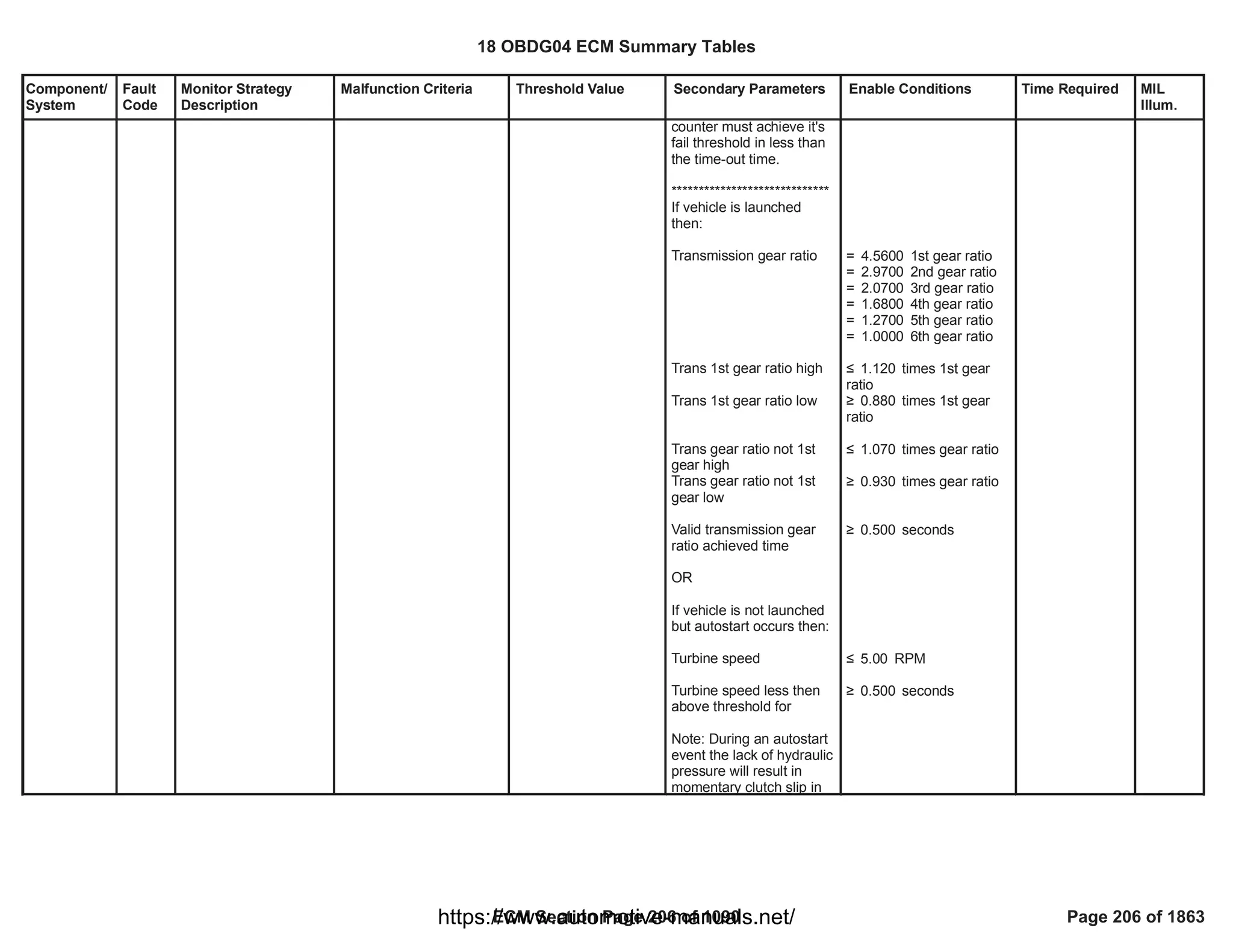
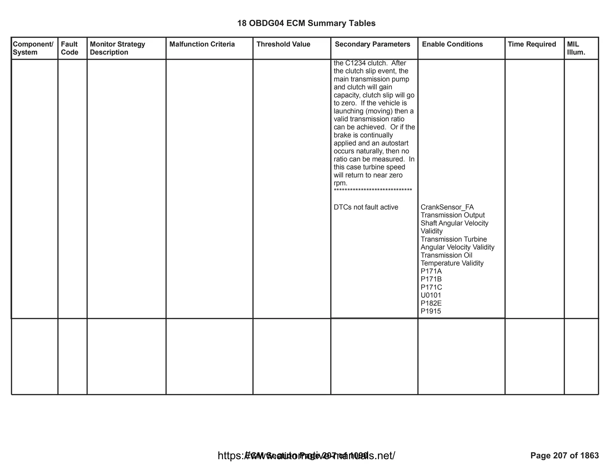
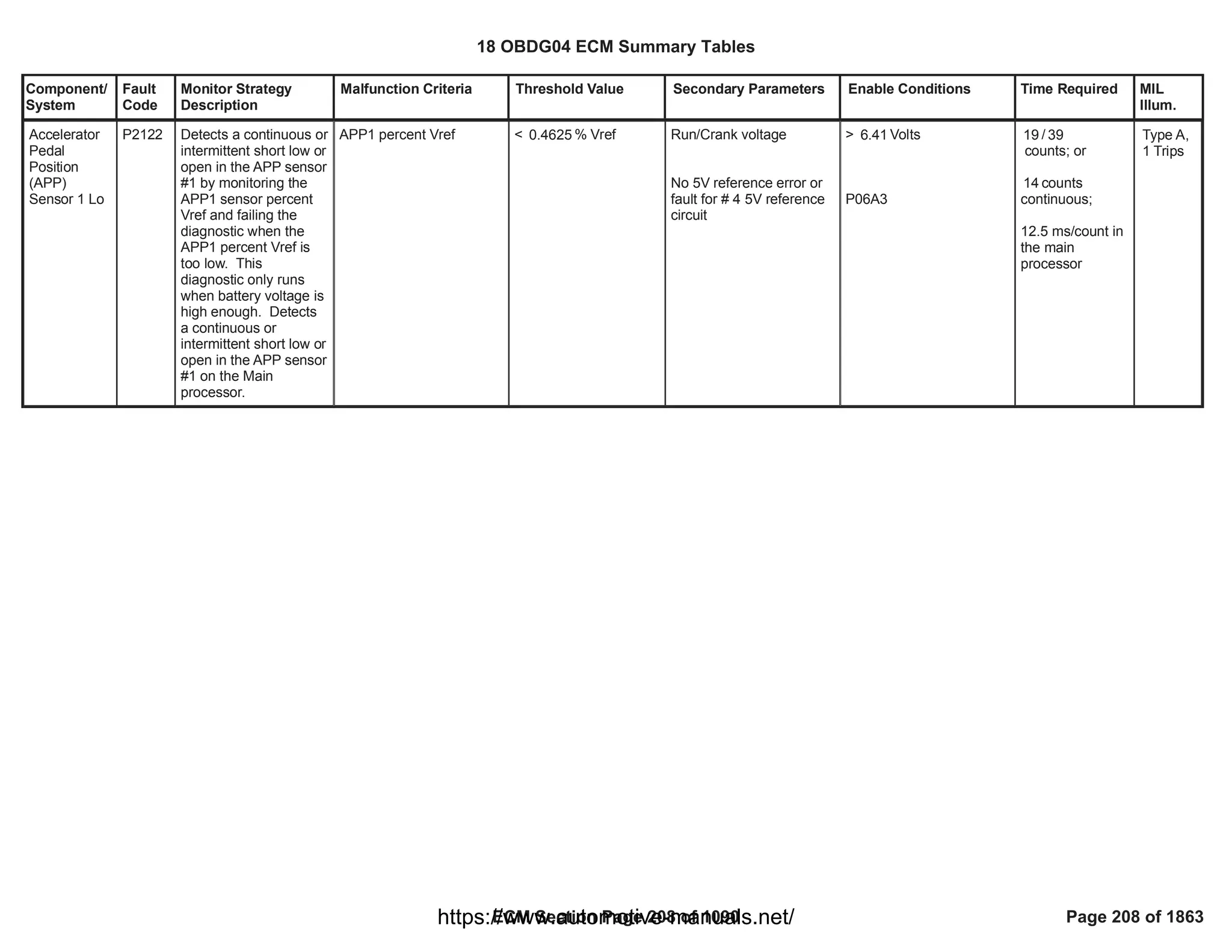
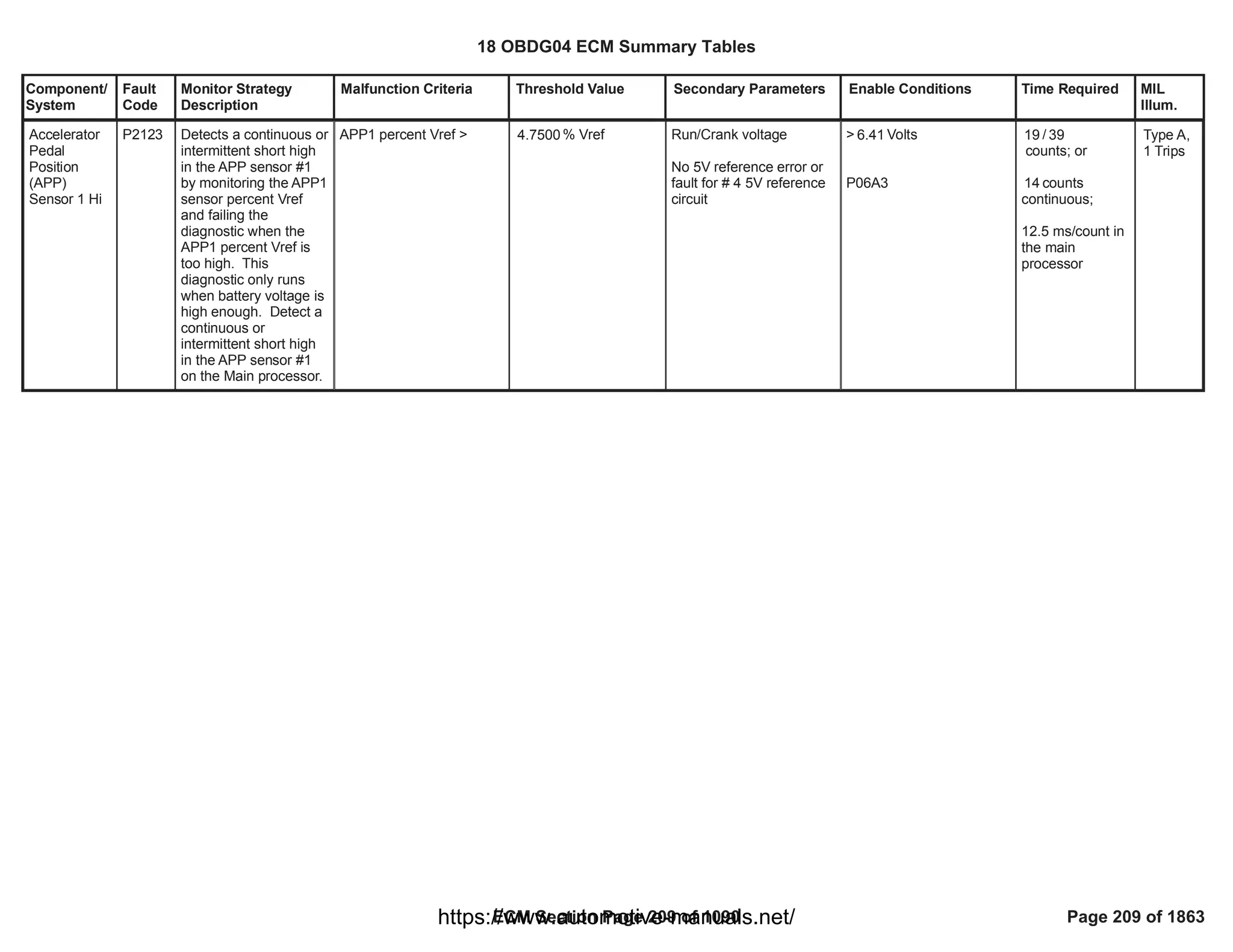

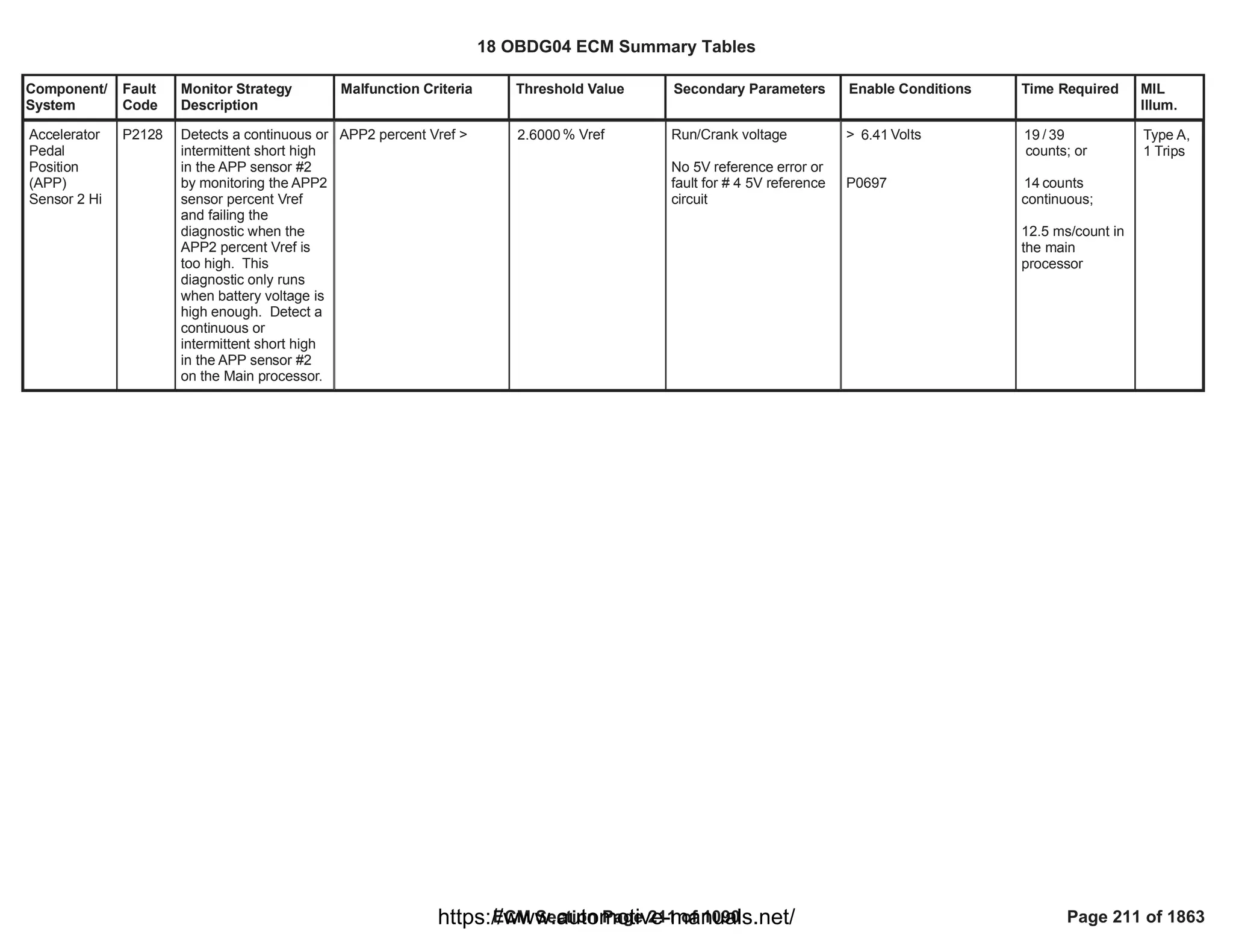
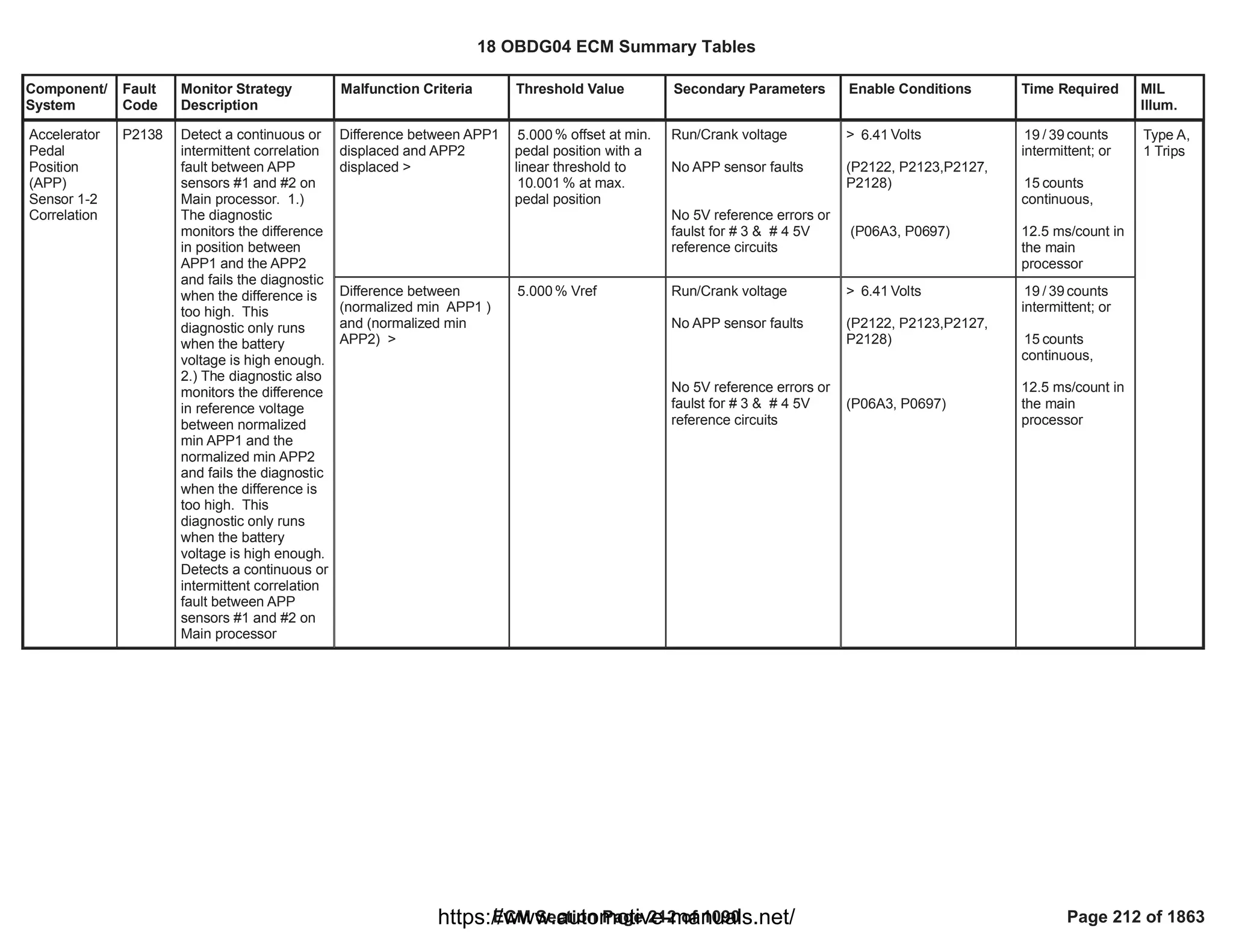
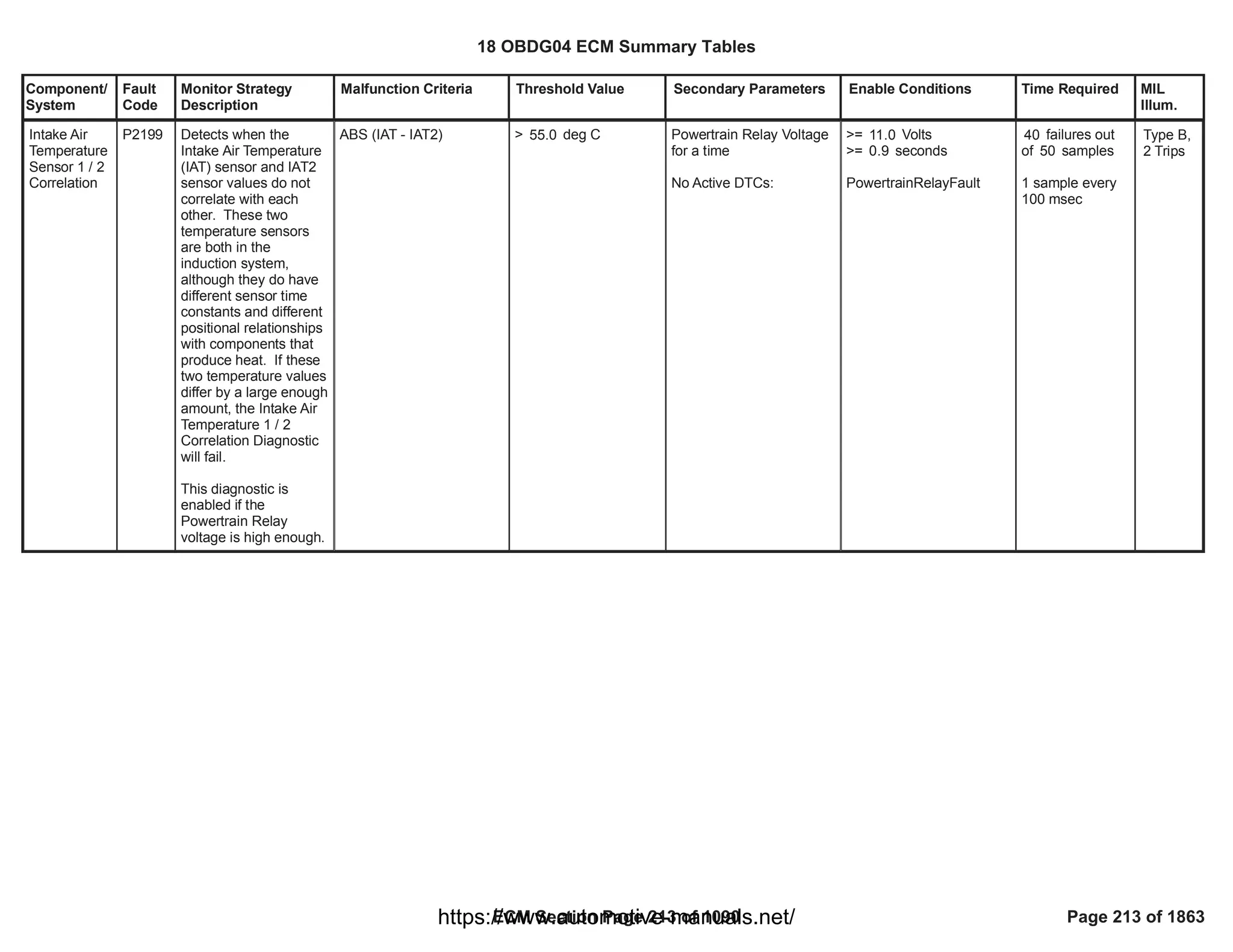
![Component/
System
Fault
Code
Monitor Strategy
Description
Malfunction Criteria Threshold Value Secondary Parameters Enable Conditions Time Required MIL
Illum.
Difference (absolute
value) in measured
pressure between BARO
sensor and TCIAP sensor
AND
Difference (absolute
value) in measured
pressure between BARO
sensor and MAP sensor
AND
Difference (absolute
value) in measured
pressure between TCIAP
sensor and MAP sensor
>
P0106, P2227, P227B,
P00C7: Maximum
pressure difference
[kPa]
>
P0106, P2227, P227B,
P00C7: Maximum
pressure difference
[kPa]
<
P0106, P2227, P227B,
P00C7: Maximum
pressure difference
[kPa]
Correlation diagnostic
enabled by calibration
Engine is running
Run Crankrelay supply
voltage in range
Engine speed
Requested fuel
Throttle measured
position
Engine Coolant
Temperature
No faults are present
== 1.00
> [V]
11.00
< [rpm]
1,100.00
< [mm^3]
20.00
> [%]
90.00
> [°C]
60.00
CrankSensor_FA
==FALSE
FUL_GenericInjSysFA
==FALSE
TPS_PstnSnsrFA
==FALSE
MAP_SensorCircuitFA
==FALSE
AAP2_SnsrCktFA
==FALSE
AAP_AAP5_SnsrCktFA
==FALSE
AAP_AAP2_SnsrStabFA
==FALSE
AAP_AAP5_SnsrStabFA
==FALSE
ECT_Sensor_FA
320.00
fail counters over
400.00
sample counters
sampling time is
12.5 ms
Barometric
Pressure
(BARO)
Sensor
Performance
(US Market -
3 pressure
sensor
configuration
)
P2227 This monitor is used to
identify BARO sensor
internal faults
(measurement with an
offset or a drift).
The plausibility monitor
compares the BARO,
MAP and TCIAP
pressures in two
different conditions:
- at idle (part of the test
enabled when the
engine is running)
- between key off and
when the engine starts
running (part of the test
enabled when the
engine is not running).
If BARO sensor is not
in agreement with the
other two the monitor is
able to pinpoint BARO
as the faulty sensor.
Type B,
2 Trips
18 OBDG04 ECM Summary Tables
ECM Section Page 214 of 1090 Page 214 of 1863
https://www.automotive-manuals.net/](https://image.slidesharecdn.com/gmcenginefaultcodesdtc1-230327071418-56d3c5bb/75/18-OBDG04-ECM-Summary-Tables-214-2048.jpg)
![Component/
System
Fault
Code
Monitor Strategy
Description
Malfunction Criteria Threshold Value Secondary Parameters Enable Conditions Time Required MIL
Illum.
==FALSE
MAF_MAF_SnsrFA
==FALSE
BARO Pressure
OR
BARO Pressure
< [kPa]
50.0
> [kPa]
115.0
Time between current
ignition cycle and the last
time the engine was
running
Engine is not rotating
No Active DTCs:
No Pending DTCs:
> [s]
5.0
EngineModeNotRunTimer
Error
MAP_SensorCircuitFA
AAP_SnsrCktFA
MAP_SensorCircuitFP
AAP_SnsrCktFP
fail counters
4
over sample
5
counters
sampling time is
12.5 ms
18 OBDG04 ECM Summary Tables
ECM Section Page 215 of 1090 Page 215 of 1863
https://www.automotive-manuals.net/](https://image.slidesharecdn.com/gmcenginefaultcodesdtc1-230327071418-56d3c5bb/75/18-OBDG04-ECM-Summary-Tables-215-2048.jpg)
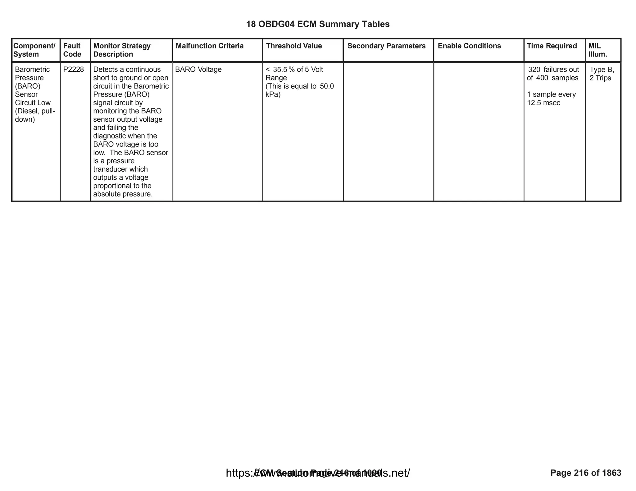


![Component/
System
Fault
Code
Monitor Strategy
Description
Malfunction Criteria Threshold Value Secondary Parameters Enable Conditions Time Required MIL
Illum.
Turbocharge
r/
Supercharge
r Boost
System A
Performance
(OBDII
market only)
P2263 This monitor is used to
detect any malfunction
in the boost pressure
control system causing
very high or low intake
manifold pressure that
could lead to
overspeed the turbine.
It works only in steady
state closed loop
pressure control zone,
tipically in the turbine
overspeed area outside
of the FTP test cycle.
The DTC checks a
positive or negative
control deviation of the
boost pressure
indicating an
underboost or
overboost condition.
The aim of the boost
pressure system
performance monitor is
to detect leakages in
the pipe after the
compressor or in the
intake/exhaust manifold
(underboost) or
obstructions in the
exhaust pipe
(overboost) that lead to
overspeed the turbine.
Boost pressure tracking
error: difference between
the desired boost
pressure and the
measured pressure at
intake manifold by MAP
sensor.
If throttle control is active:
The setpoint used for
closed loop control is the
conversion of the desired
upstream throttle boost
pressure (target) in
desired intake boost
pressure.
The conversion of the
setpoint is done
calculating the pressure
drop over the throttle
valve that is strictly
dependent on the valve
position.
If throttle control is NOT
active:
The setpoint used for
closed loop control is the
intake manifold pressure:
in this situation the
diagnostic monitors the
boost pressure closed
loop control tracking error.
If throttle control is
active (Refer to "Other
AICR DSL flags" Free
Form):
<
(
P2263: Boost
pressure system
performance
negative error
threshold (throttle
control active)
[kPa]
x
P0234, P2263:
Overboost
barometric correction
)
OR
>
(
P2263: Boost
pressure system
performance positive
error threshold
(throttle control
active)
[kPa]
x
P0299, P2263:
Underboost
barometric correction
)
If throttle control is
NOT active (Refer to
"Other AICR DSL
Calibration on diagnostic
enabling
Engine Running
Cranking ignition in range
PT Relay voltage in range
Difficult launch NOT
detected
Boost Pressure Control
Closed Loop active
No active transition from a
combustion mode to
another one
Outside Air Temperature
in range
Desired Boost Pressure
steady state:
BstDes-BstDes_Old
(Engine Coolant
Temperature
==TRUE
1.00
==TRUE
Battery voltage > 11.00
[V]
Powertrain relay voltage >
[V]
11.00
Refer to
"LDT_DifficultLaunchActiv
e" Free Form
Refer to "Boost Control in
Closed Loop" Free Form
==TRUE
> [°C]
-7.00
AND
< [°C]
80.00
> [kPa/s]
-5
AND
< [kPa/s]
5
> [°C]
60
fail
400.00
counters over
sample
500.00
counters
sampling time is
25ms
Type A,
1 Trips
18 OBDG04 ECM Summary Tables
ECM Section Page 219 of 1090 Page 219 of 1863
https://www.automotive-manuals.net/](https://image.slidesharecdn.com/gmcenginefaultcodesdtc1-230327071418-56d3c5bb/75/18-OBDG04-ECM-Summary-Tables-219-2048.jpg)
![Component/
System
Fault
Code
Monitor Strategy
Description
Malfunction Criteria Threshold Value Secondary Parameters Enable Conditions Time Required MIL
Illum.
flags" Free Form):
<
(
P2263: Boost
pressure system
performance
negative error
threshold (throttle
control not active)
[kPa]
x
P0234, P2263:
Overboost
barometric correction
)
OR
>
(
P2263: Boost
pressure system
performance positive
error threshold
(throttle control not
active)
[kPa]
x
P0299, P2263:
Underboost
barometric correction
)
OR
OBD Coolant Enable
Criteria),
AND
Engine Coolant
Temperature
Ambient Air Pressure in
range
Throttle Valve position
Engine speed in range
Desired intake Boost
pressure in range
No active DTCs
All enabling conditions
last for a time
==TRUE
< [°C]
124
> [kPa]
75
AND
< [kPa]
120
>= [%] if throttle
90.00
control is active (Refer to
"Other AICR DSL flags"
Free Form)
>= [%] if throttle
90.00
control is NOT active
(Refer to "Other AICR
DSL flags" Free Form)
> [rpm]
2,250.00
AND
< [rpm]
4,500.00
> [kPa]
130.00
AND
< [kPa]
300.00
AIC_BstSysDiagDenomD
sbl
==FALSE
>
18 OBDG04 ECM Summary Tables
ECM Section Page 220 of 1090 Page 220 of 1863
https://www.automotive-manuals.net/](https://image.slidesharecdn.com/gmcenginefaultcodesdtc1-230327071418-56d3c5bb/75/18-OBDG04-ECM-Summary-Tables-220-2048.jpg)
![Component/
System
Fault
Code
Monitor Strategy
Description
Malfunction Criteria Threshold Value Secondary Parameters Enable Conditions Time Required MIL
Illum.
P2263: Boost pressure
system performance
monitor delay timer
[s]
18 OBDG04 ECM Summary Tables
ECM Section Page 221 of 1090 Page 221 of 1863
https://www.automotive-manuals.net/](https://image.slidesharecdn.com/gmcenginefaultcodesdtc1-230327071418-56d3c5bb/75/18-OBDG04-ECM-Summary-Tables-221-2048.jpg)
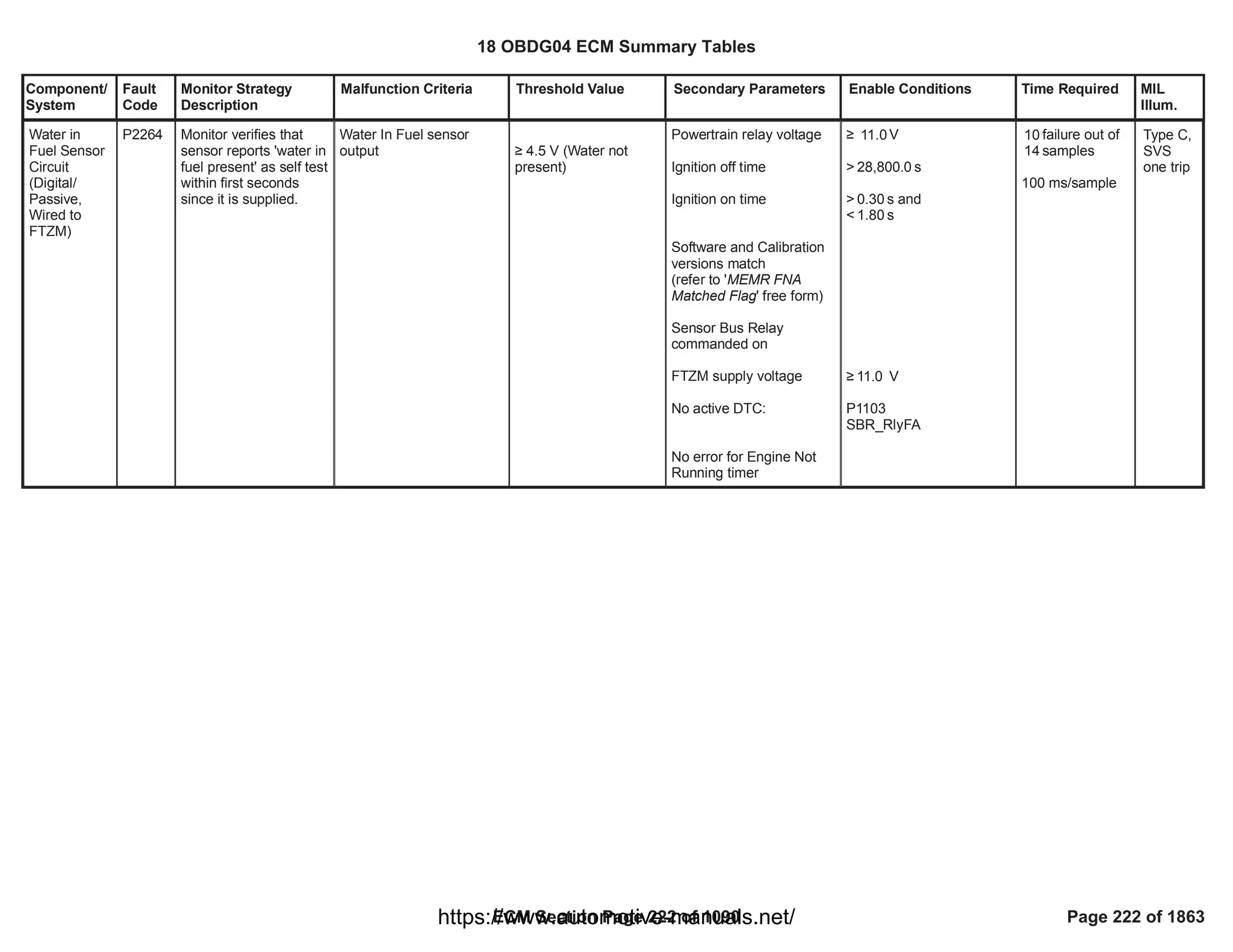
![Component/
System
Fault
Code
Monitor Strategy
Description
Malfunction Criteria Threshold Value Secondary Parameters Enable Conditions Time Required MIL
Illum.
Difference (absolute
value) in measured
pressure between BARO
sensor and TCIAP sensor
AND
Difference (absolute
value) in measured
pressure between TCIAP
sensor and MAP sensor
AND
Difference (absolute
value) in measured
pressure between BARO
sensor and MAP sensor
>
P0106, P2227, P227B,
P00C7: Maximum
pressure difference
[kPa]
>
P0106, P2227, P227B,
P00C7: Maximum
pressure difference
[kPa]
<
P0106, P2227, P227B,
P00C7: Maximum
pressure difference
[kPa]
Correlation diagnostic
enabled by calibration
Engine is running
Run Crank relay supply
voltage in range
Engine speed
Requested fuel
Throttle measured
position
Engine Coolant
Temperature
No faults are present
== 1.00
> [V]
11.00
< [rpm]
1,100.00
< [mm^3]
20.00
> [%]
90.00
> [°C]
60.00
CrankSensor_FA
==FALSE
FUL_GenericInjSysFA
==FALSE
TPS_PstnSnsrFA
==FALSE
MAP_SensorCircuitFA
==FALSE
AAP2_SnsrCktFA
==FALSE
AAP_AAP5_SnsrCktFA
==FALSE
AAP_AAP2_SnsrStabFA
==FALSE
AAP_AAP5_SnsrStabFA
==FALSE
fail
320.00
counters over
sample
400.00
counters
sampling time is
12.5 ms
Turbocharge
r Inlet
Pressure
(TCIAP)
Sensor
Performance
(US Market -
3 pressure
sensor
configuration
)
P227B This monitor is used to
identify TCIAP sensor
internal faults
(measurement with an
offset or a drift).
The plausibility monitor
compares the BARO,
MAP and TCIAP
pressures in two
different conditions:
- at idle (part of the test
enabled when the
engine is running)
- between key off and
when the engine starts
running (part of the test
enabled when the
engine is not running)
If TCIAP sensor is not
in agreement with the
other two the monitor is
able to pinpoint TCIAP
as the faulty sensor.
Type B,
2 Trips
18 OBDG04 ECM Summary Tables
ECM Section Page 223 of 1090 Page 223 of 1863
https://www.automotive-manuals.net/](https://image.slidesharecdn.com/gmcenginefaultcodesdtc1-230327071418-56d3c5bb/75/18-OBDG04-ECM-Summary-Tables-223-2048.jpg)
![Component/
System
Fault
Code
Monitor Strategy
Description
Malfunction Criteria Threshold Value Secondary Parameters Enable Conditions Time Required MIL
Illum.
ECT_Sensor_FA
==FALSE
MAF_MAF_SnsrFA
==FALSE
TCIAP Pressure
OR
TCIAP Pressure
< [kPa]
50.0
> [kPa]
115.0
Time between current
ignition cycle and the last
time the engine was
running
Engine is not rotating
No Active DTCs:
No Pending DTCs:
> [s]
5.0
EngineModeNotRunTimer
Error
MAP_SensorCircuitFA
AAP_SnsrCktFA
AAP2_SnsrCktFA
AAP3_SnsrCktFA
MAP_SensorCircuitFP
AAP_SnsrCktFP
AAP2_SnsrCktFP
AAP3_SnsrCktFP
fail counters
4
over sample
5
counters
sampling time is
12.5ms
18 OBDG04 ECM Summary Tables
ECM Section Page 224 of 1090 Page 224 of 1863
https://www.automotive-manuals.net/](https://image.slidesharecdn.com/gmcenginefaultcodesdtc1-230327071418-56d3c5bb/75/18-OBDG04-ECM-Summary-Tables-224-2048.jpg)
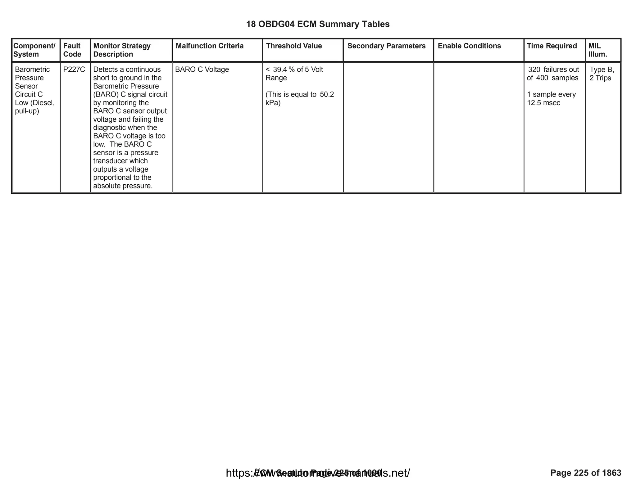

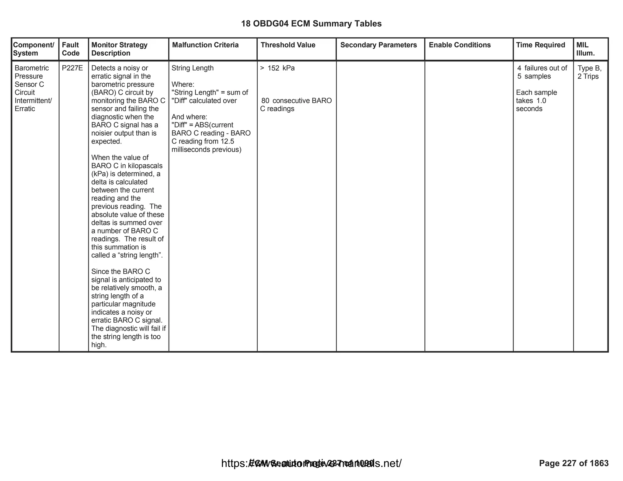
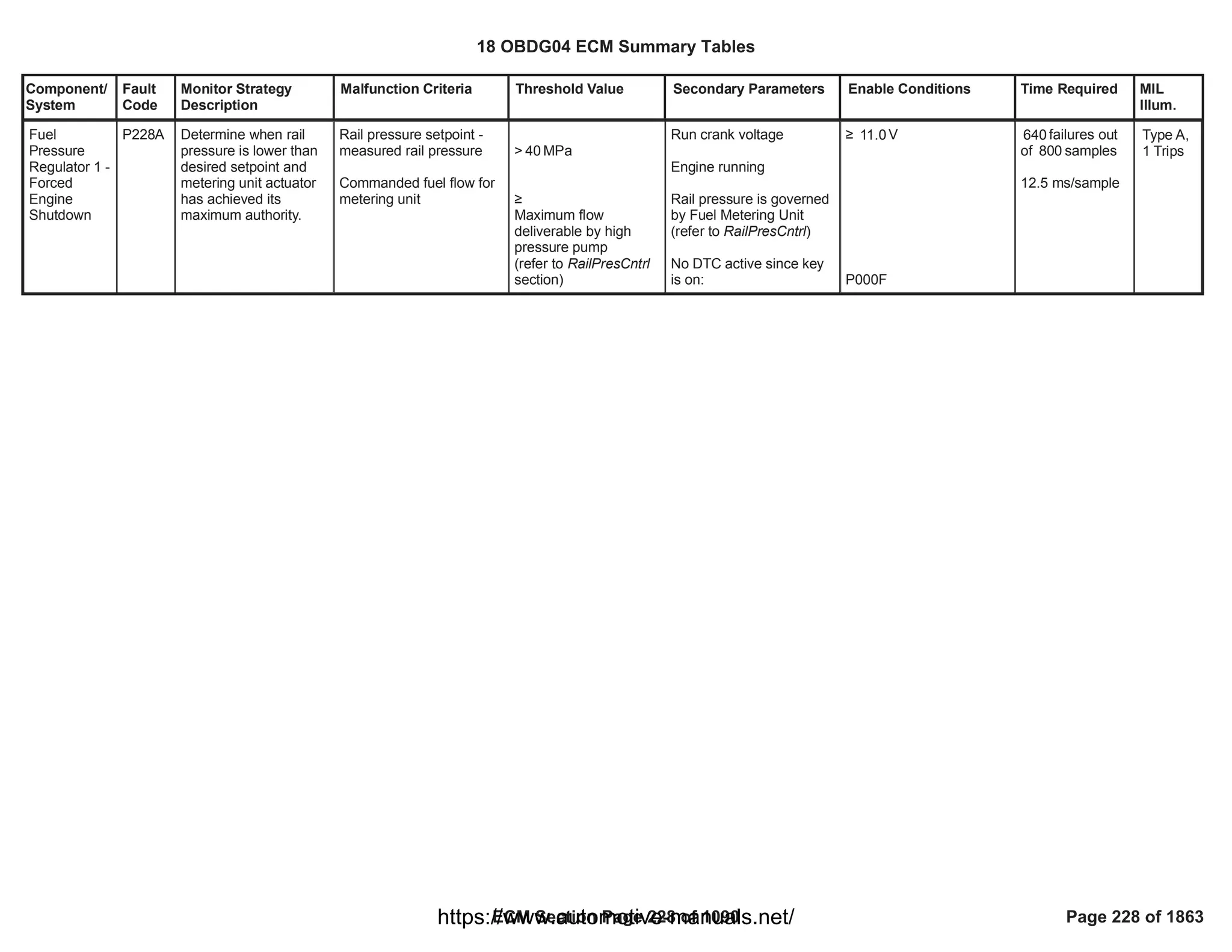
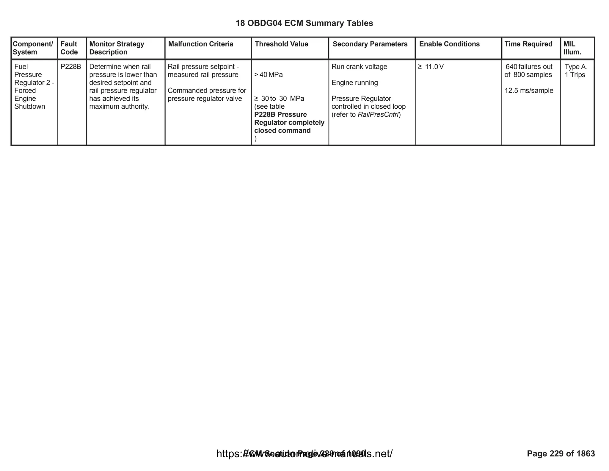
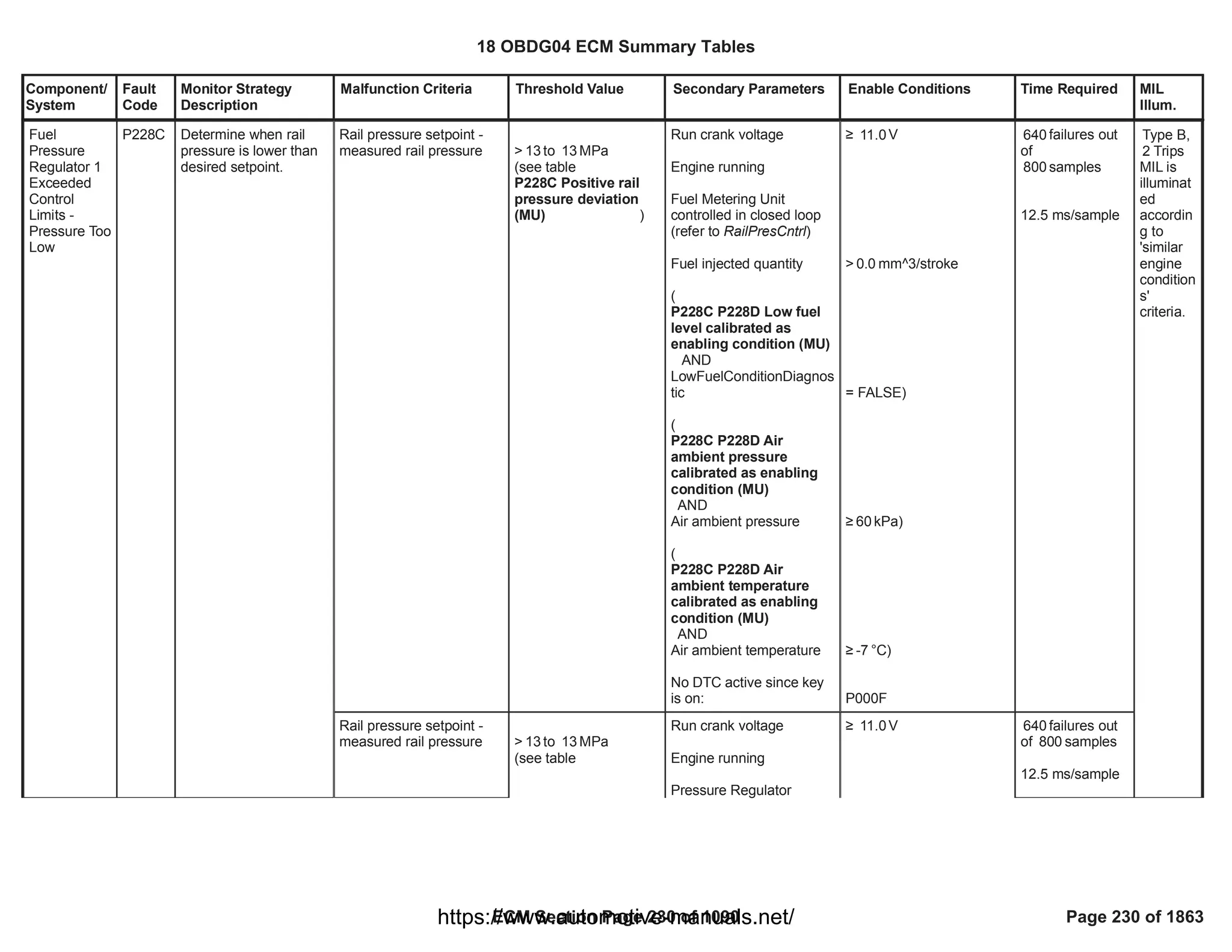
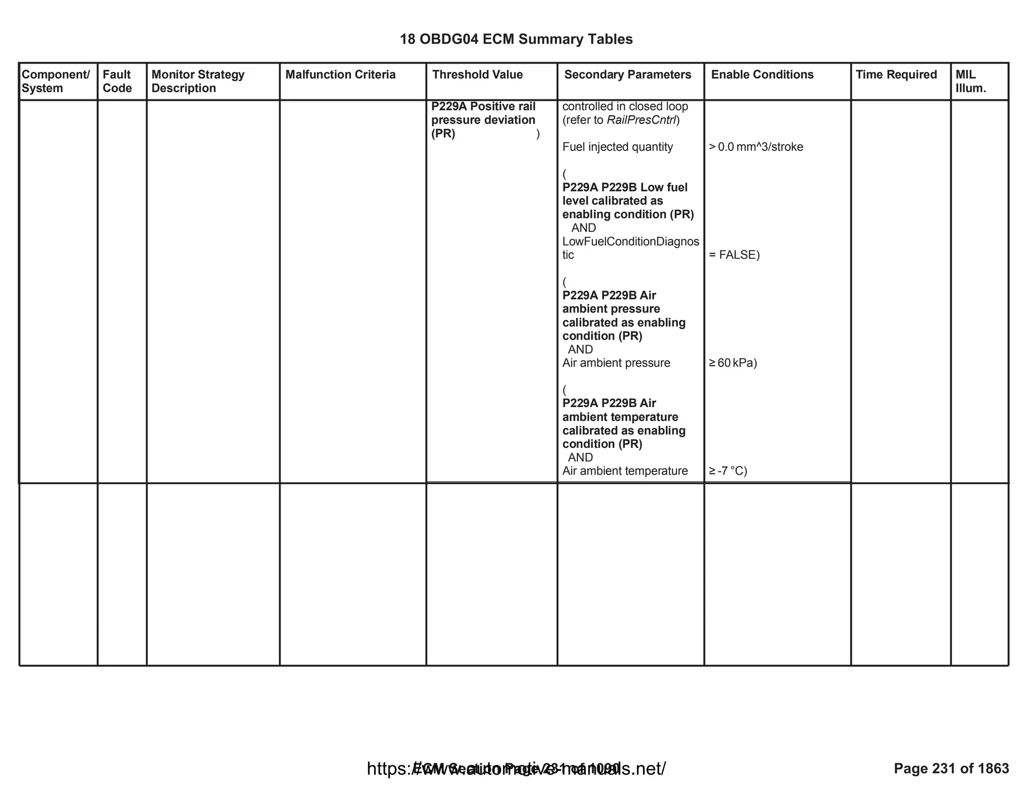
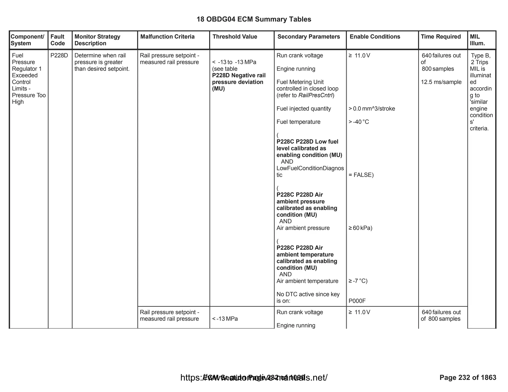
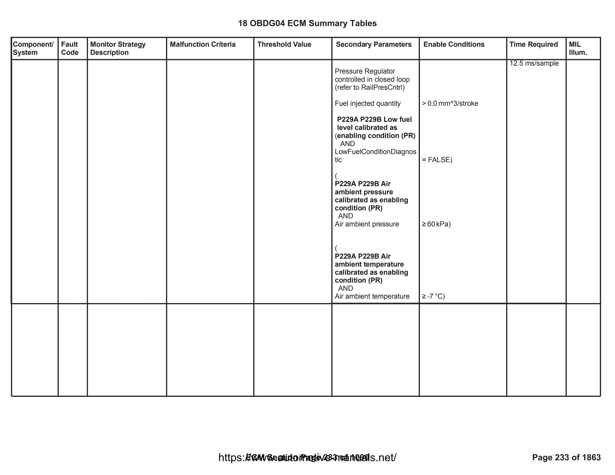

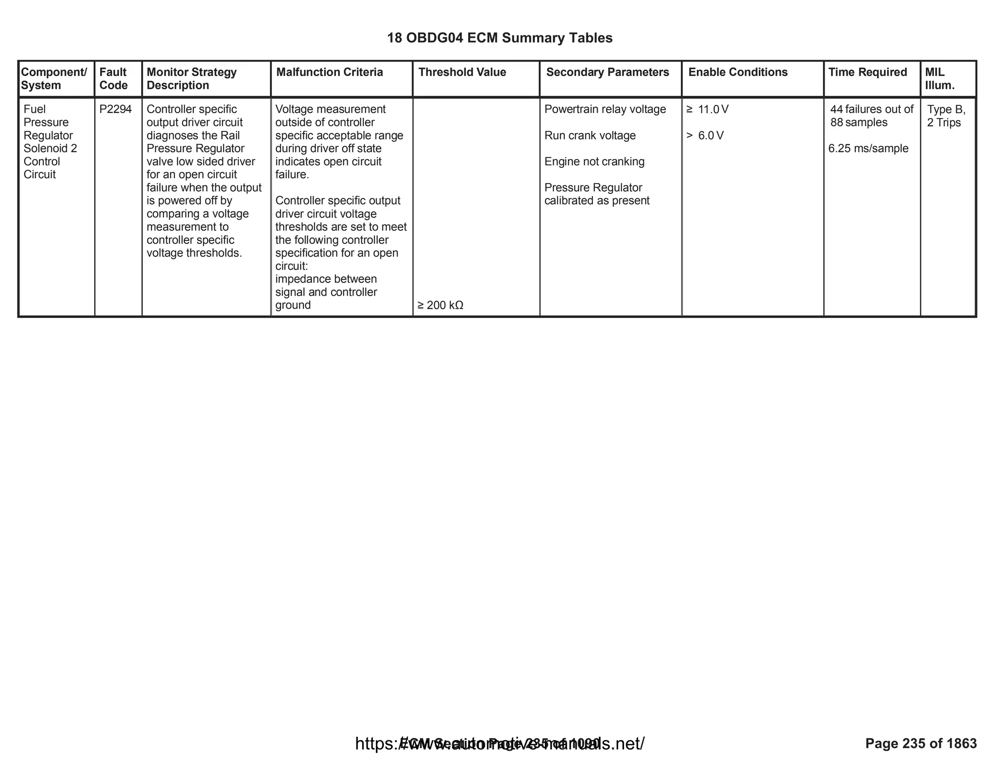
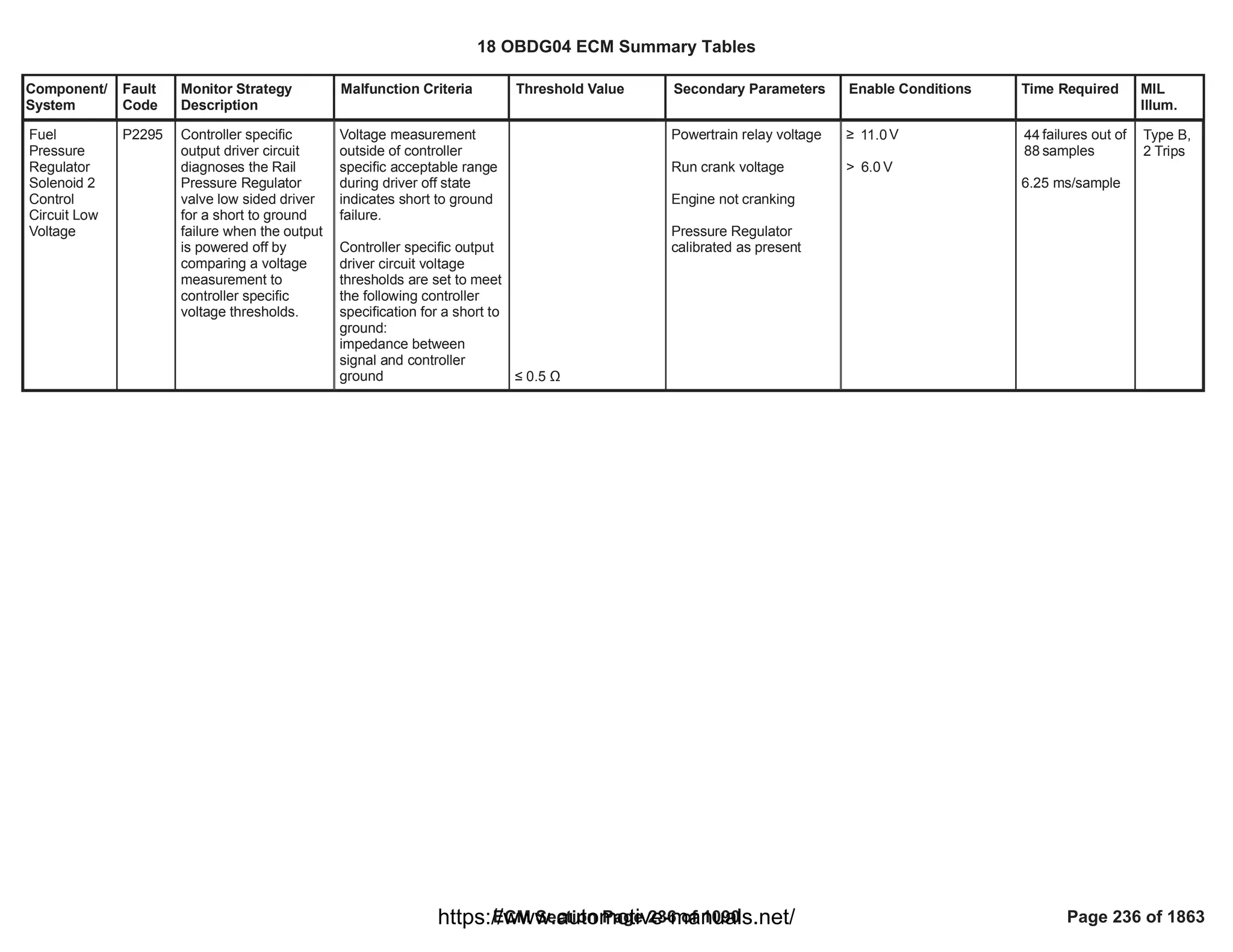

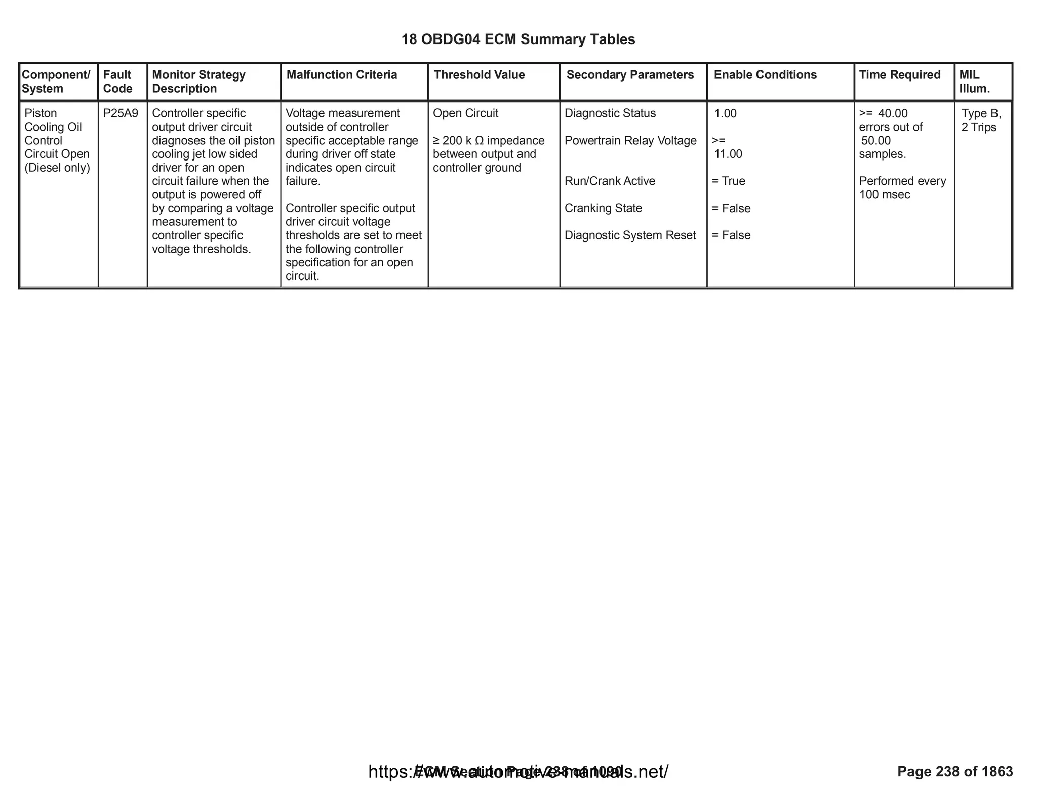
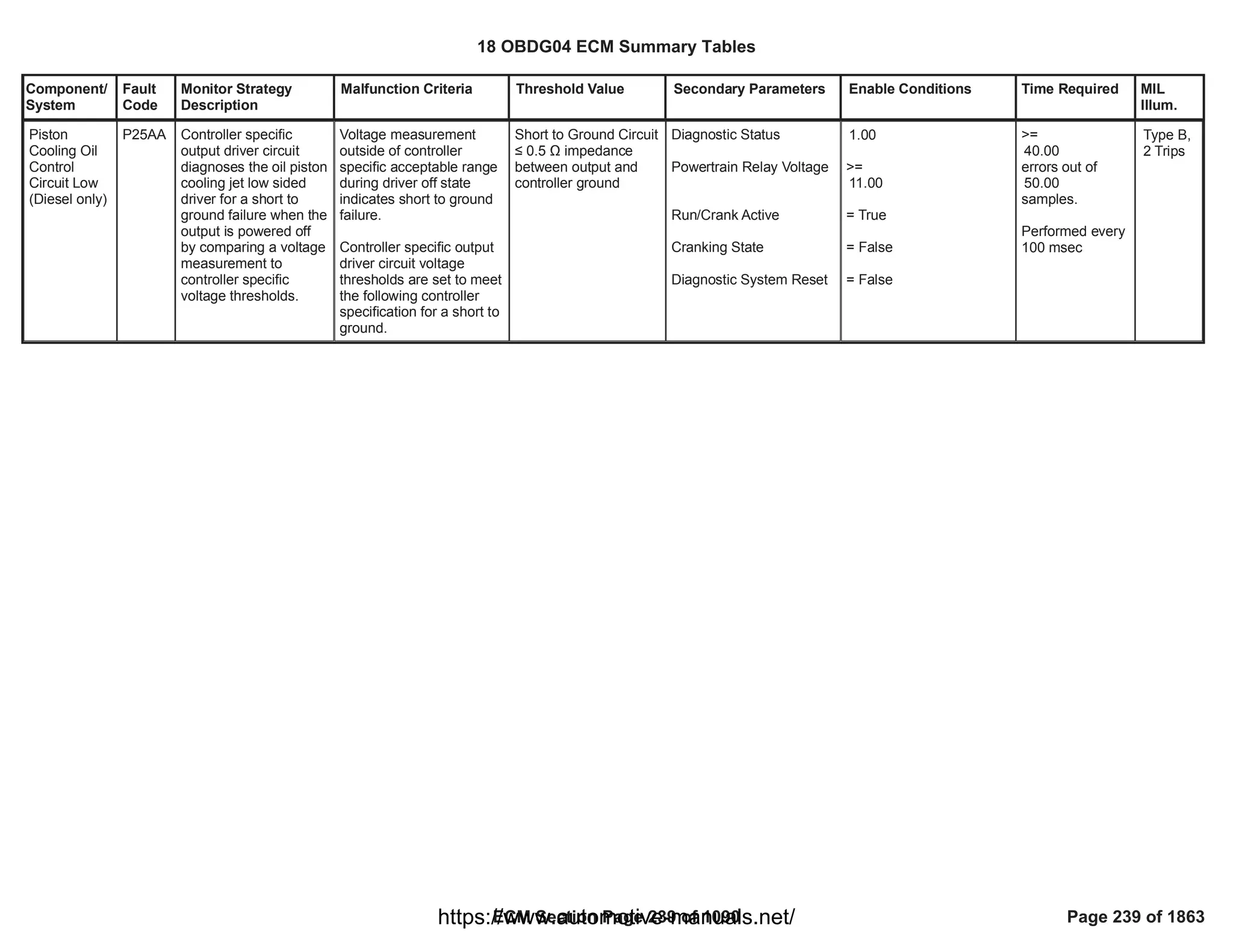

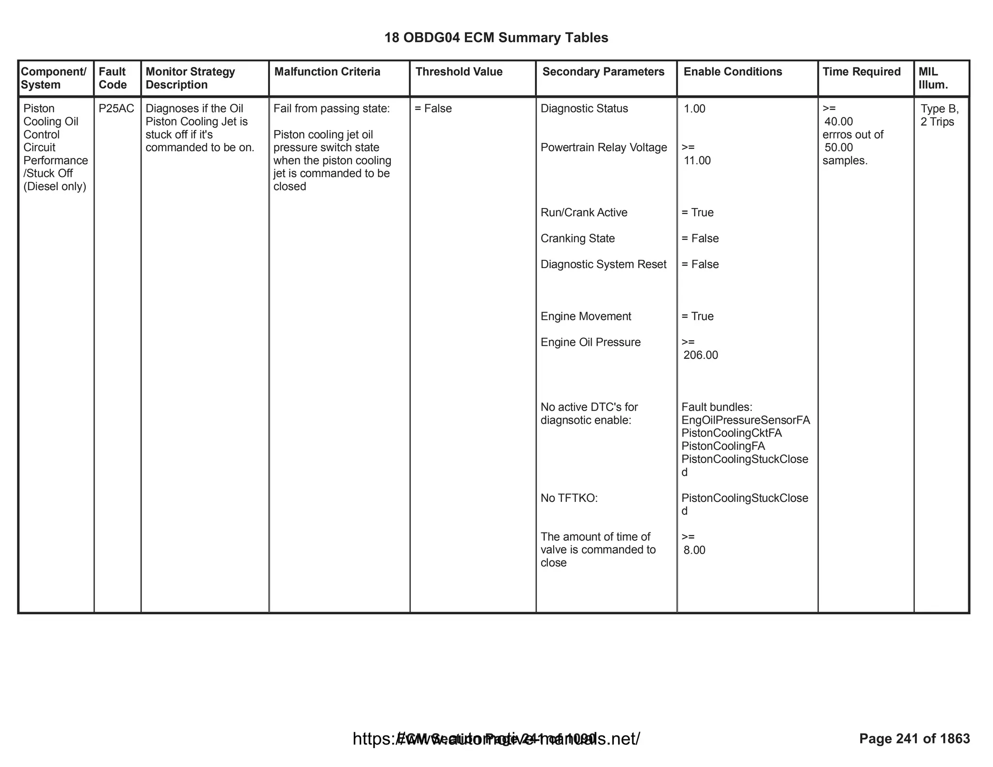
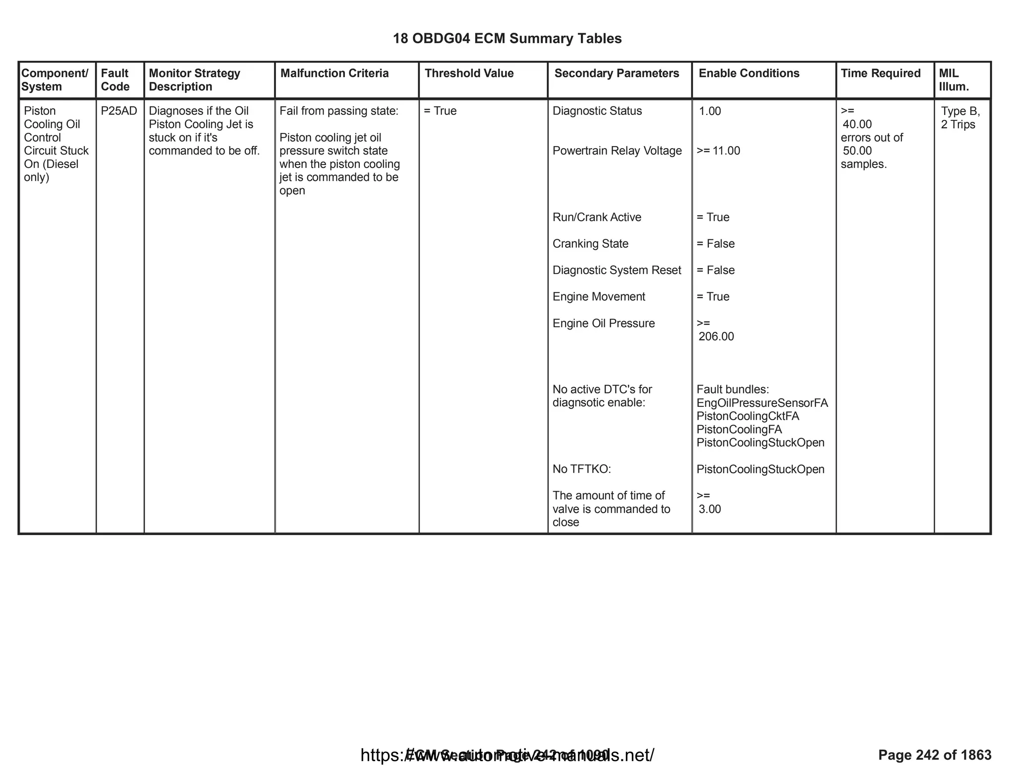
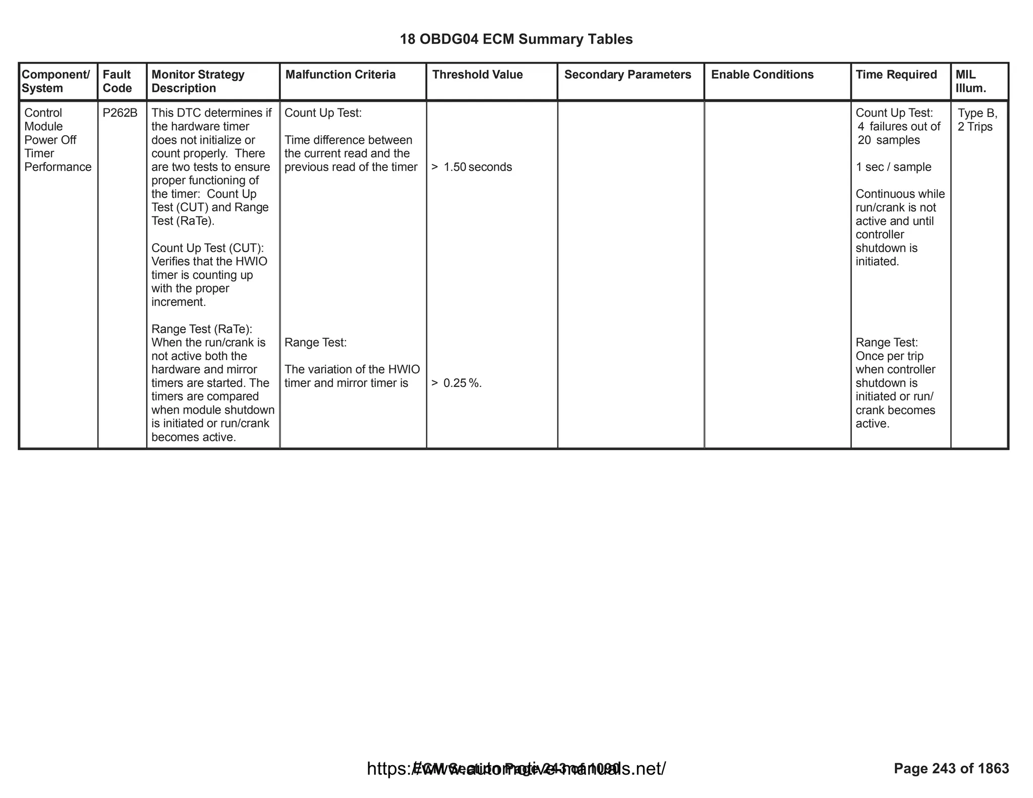
![Component/
System
Fault
Code
Monitor Strategy
Description
Malfunction Criteria Threshold Value Secondary Parameters Enable Conditions Time Required MIL
Illum.
Fuel Pump
"A" Low
Flow /
Performance
P2635 This DTC detects
degradation in the
performance of the
electronically regulated
fuel system by
calculating the
difference between the
sensed, filtered system
[line] pressure versus
the ECM-commanded
pressure [error
calculation]. The
calculated error is then
compared to calibrated
fault threshold tables
for a fault decision.
Sensed Filtered Fuel
System [line] pressure
error
<= Low Threshold
[Supporting Table]
P2635 Threshold Low
OR
>= High Threshold
[Supporting Table]
P2635 Threshold
High
a) Diagnostic enabled
[FDBR_b_FSRD]
b) Timer Engine Running
[FDBR_t_EngModeRunC
oarse]
c1) Fuel Flow Rate Valid
c2) Ambient Air Pressure
Value Defaulted
c3)
FDB_FuelPresSnsrCktFA
c4) Reference Voltage
Fault Status [DTC P0641]
c5) Exhaust
AfterTreatment Fuel
Injector A Control Circuit
Short Low Fault
[HCIR_b_GshtFA DTC
P20CD]
c6) Fuel Pres Sensor
Performance Fault Active
[DTC P018B]
c7) Use Calculated Flow
Performance Fault
Thresholds
[FDBR_b_UseCalcFSRD
_FltThrshs]
c8) Engine Speed Status
Valid
c9) FAB_FuelPmpCktFA
c10) Fuel Control Enable
a) == TRUE
b) >= seconds
40.00
c1) == TRUE
c2) <> TRUE
c3) <> TRUE
c4) <> TRUE
c5) <> TRUE
c6) <> TRUE
c7) <> TRUE
c8] == TRUE
c9] <> TRUE
c10) <> TRUE
1 sample /
12.5 millisec
Type B,
2 Trips
18 OBDG04 ECM Summary Tables
ECM Section Page 244 of 1090 Page 244 of 1863
https://www.automotive-manuals.net/](https://image.slidesharecdn.com/gmcenginefaultcodesdtc1-230327071418-56d3c5bb/75/18-OBDG04-ECM-Summary-Tables-244-2048.jpg)
![Component/
System
Fault
Code
Monitor Strategy
Description
Malfunction Criteria Threshold Value Secondary Parameters Enable Conditions Time Required MIL
Illum.
Fault Active [DTC P12A6]
c11) Fuel Pump Driver
Module OverTemp Fault
Active [DTC P1255]
c12) Fuel Pump Speed
Fault Active [DTC P129F]
c13) CAN Sensor Bus
message $0C3 Comm
Fault
[CFMR_b_FTZM_Info1_U
codeCmFA DTC P165C]
c14) CAN Sensor Bus
Fuel Pmp Spd Command
ARC and Checksum
Comm Fault Code
[CFMR_b_FTZM_Cmd1_
UcodeCmFA DTC]
c15) Sensor Configuration
[FDBR_e_FuelPresSnsrC
onfig]
c16) Sensor Bus Relay
On
d) Emissions Fuel Level
Low [Message $3FB]
e) Fuel Control Enable
f) Fuel Pump Control
State
g) Run_Crank input circuit
voltage
h) High Pres Fuel Pump
c11) <> TRUE
c12) <> TRUE
c13) <> TRUE
c14] <> TRUE
c15) ==
CeFDBR_e_WiredTo_FT
ZM
c16) == TRUE
d) <> TRUE
e) == TRUE
f) == NORMAL
g) volts <=
11.00
Run_Crank_V <= 32.00
volts
h) <> TRUE
18 OBDG04 ECM Summary Tables
ECM Section Page 245 of 1090 Page 245 of 1863
https://www.automotive-manuals.net/](https://image.slidesharecdn.com/gmcenginefaultcodesdtc1-230327071418-56d3c5bb/75/18-OBDG04-ECM-Summary-Tables-245-2048.jpg)
![Component/
System
Fault
Code
Monitor Strategy
Description
Malfunction Criteria Threshold Value Secondary Parameters Enable Conditions Time Required MIL
Illum.
Mode Management
Enabled
j) High Pres Fuel Pump
Control Mode
k) Instantaneous Fuel
Flow
[FCBR_dm_InstFuelFlow]
m1) Fuel Pmp Speed
Command Alive Rolling
Count and Checksum
Error [CAN Bus B $0CE]
[CFMR_b_FTZM_Cmd1_
ARC_ChkErr DTC]
m2) CAN Sensor Bus
message $0C3_Available
m3) Fuel Pres Sensor Ref
Voltage Status Message
Counter Incorrect Alive
Rolling Count and
Checksum Error [CAN
Bus B $0C3]
[CFMR_b_FTZM_Info1_A
RC_ChkErr DTC]
n) Timer - Diagnostic
Enable
j) <> Disabled Mode
AND
a8b) <> ZeroFlow Mode
k) grams/sec <=
0.05
InstFuelFlow <= Max
Allowed Flow
[Supporting Table]
P2635 Max Fuel Flow
m1) <> TRUE
m2) == TRUE
m3) <> TRUE
n) >
seconds
2.00
18 OBDG04 ECM Summary Tables
ECM Section Page 246 of 1090 Page 246 of 1863
https://www.automotive-manuals.net/](https://image.slidesharecdn.com/gmcenginefaultcodesdtc1-230327071418-56d3c5bb/75/18-OBDG04-ECM-Summary-Tables-246-2048.jpg)
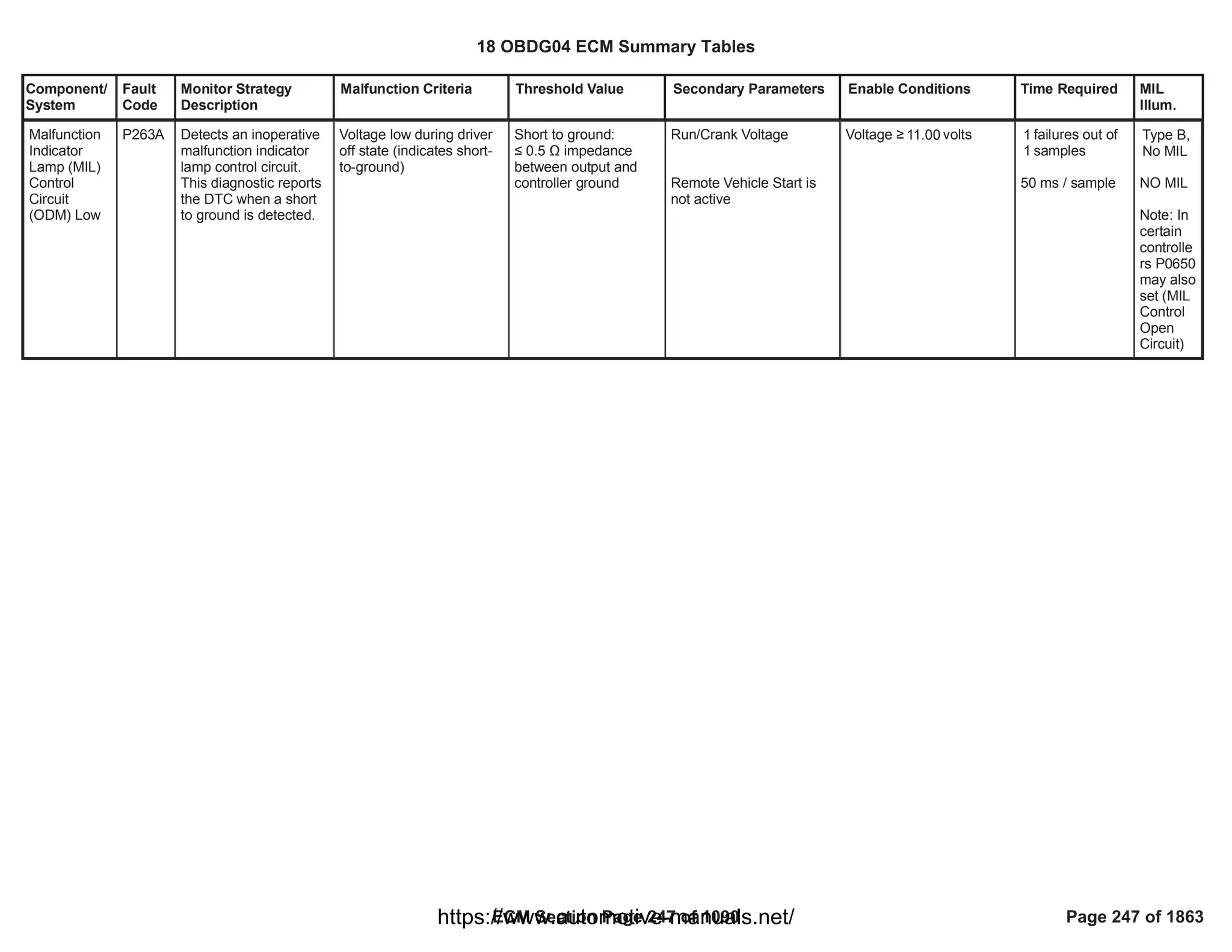
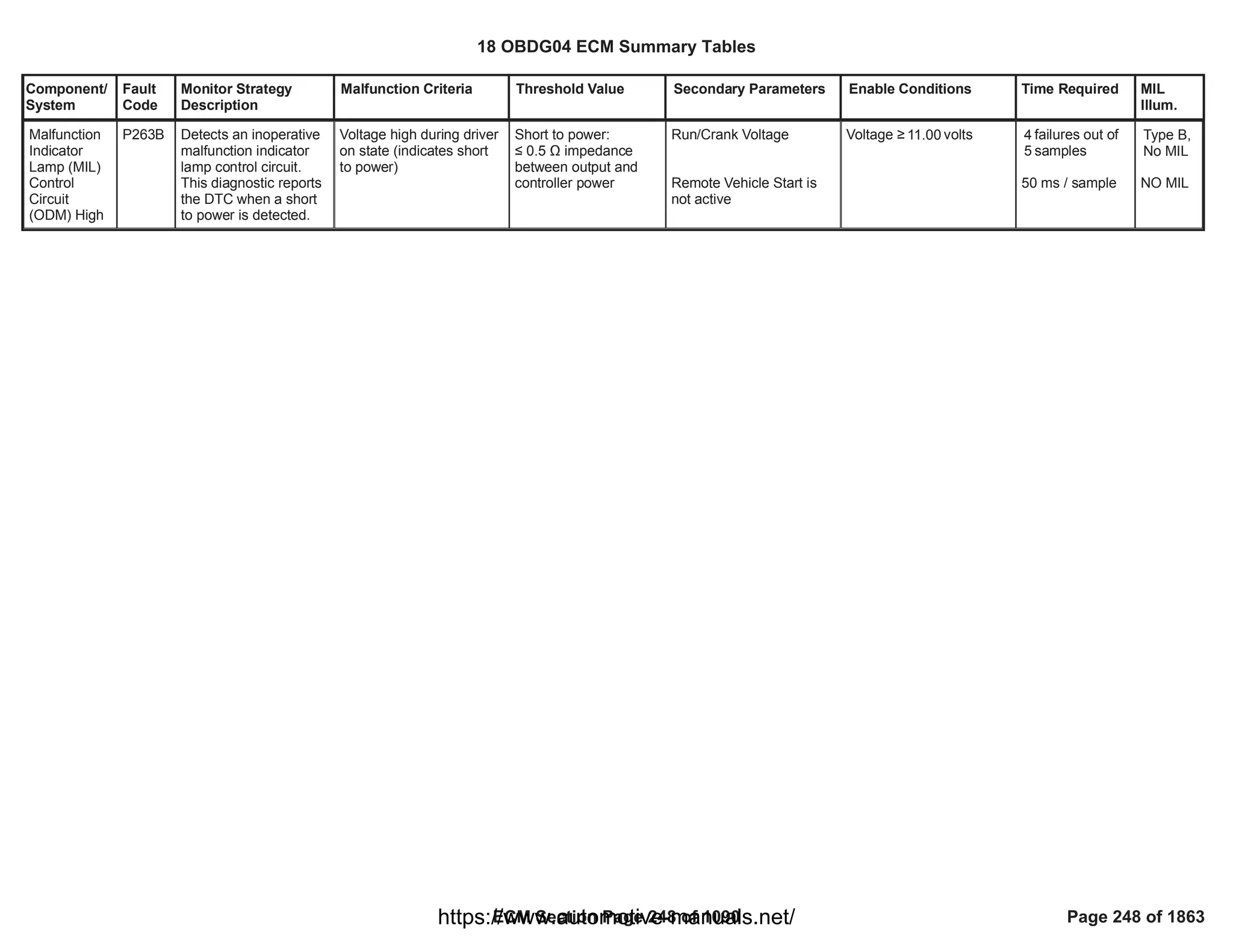
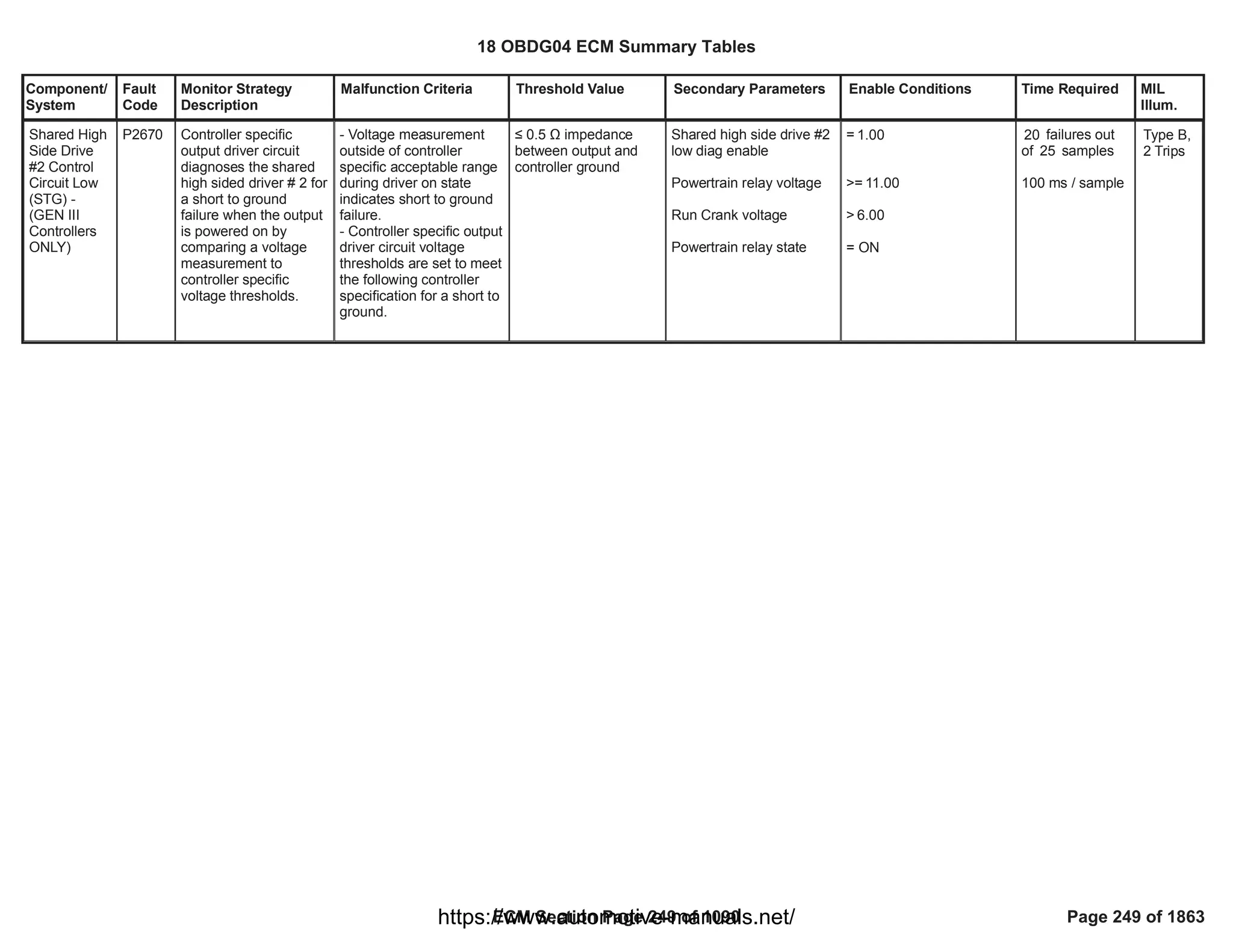

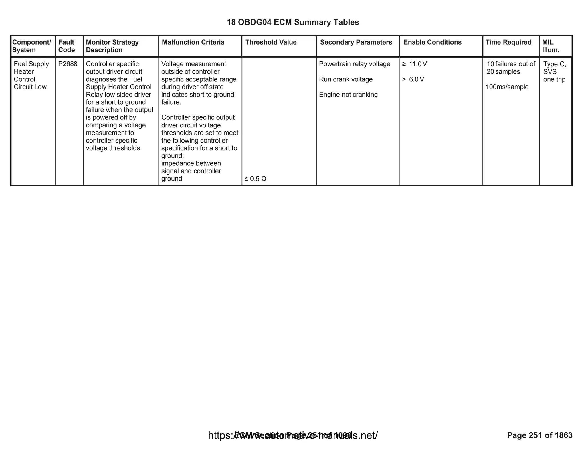
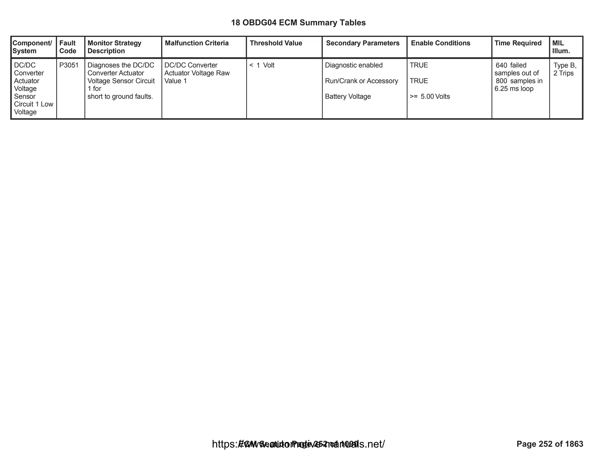


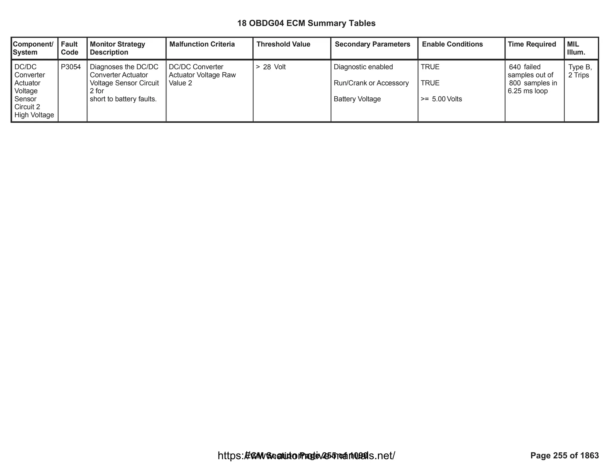
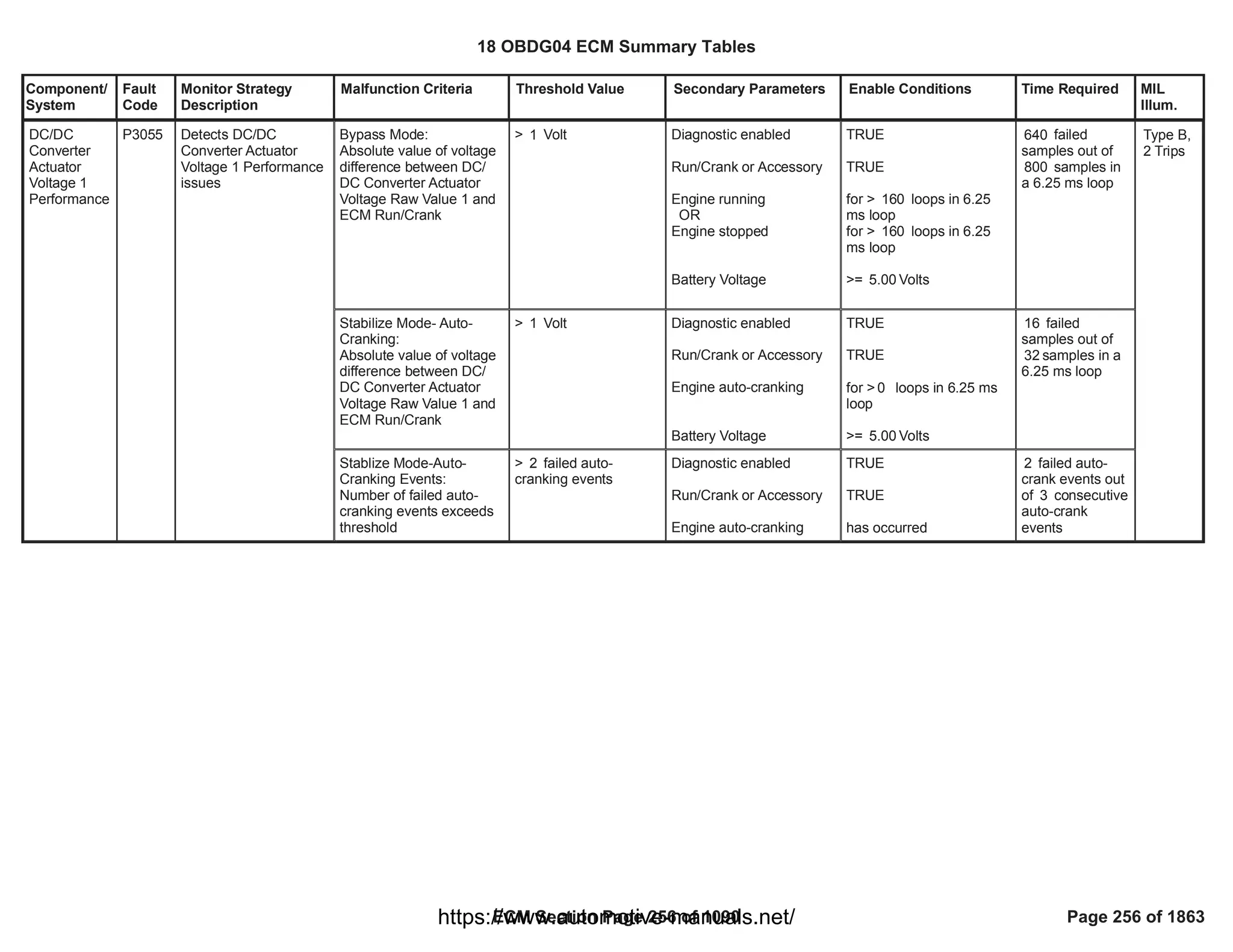

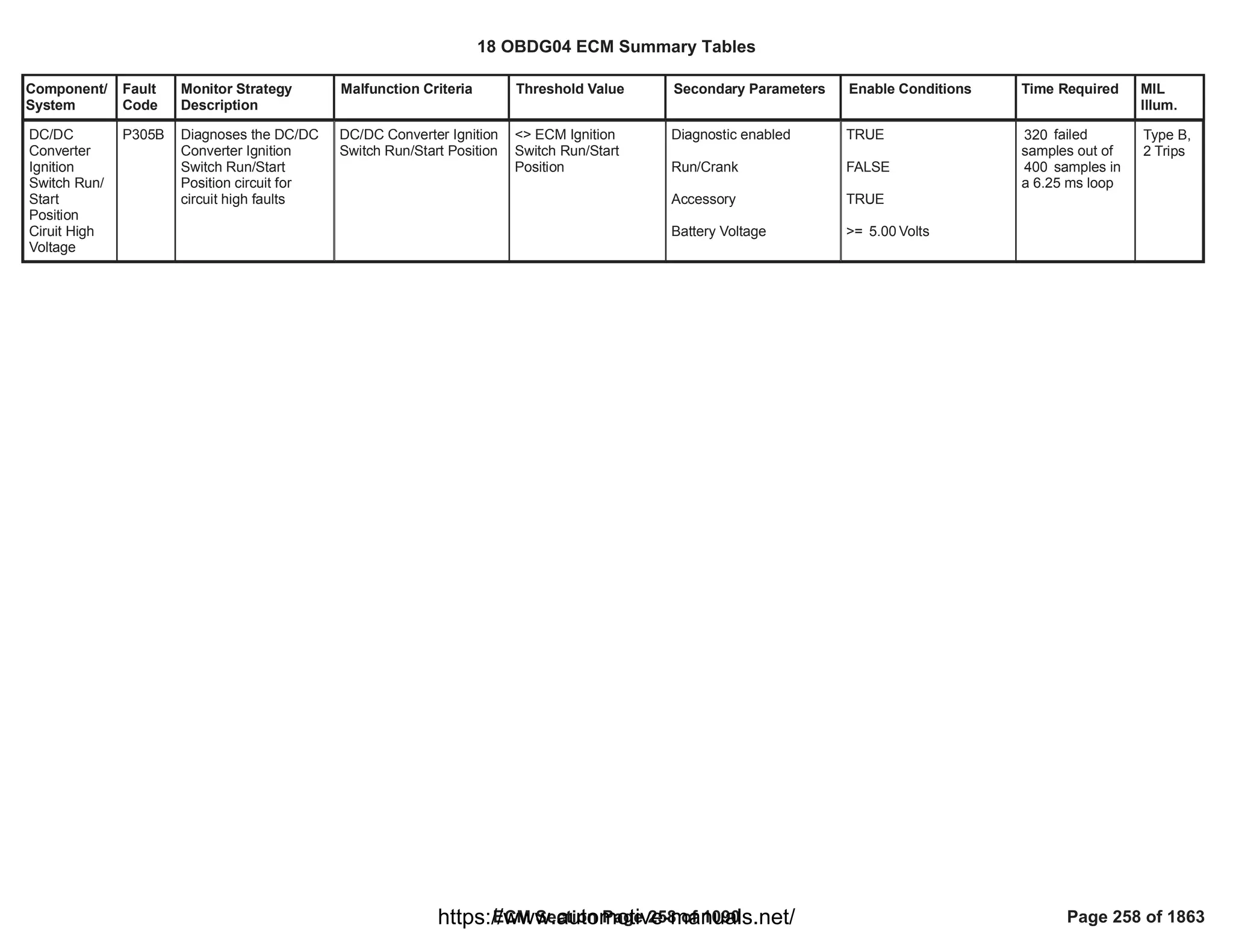
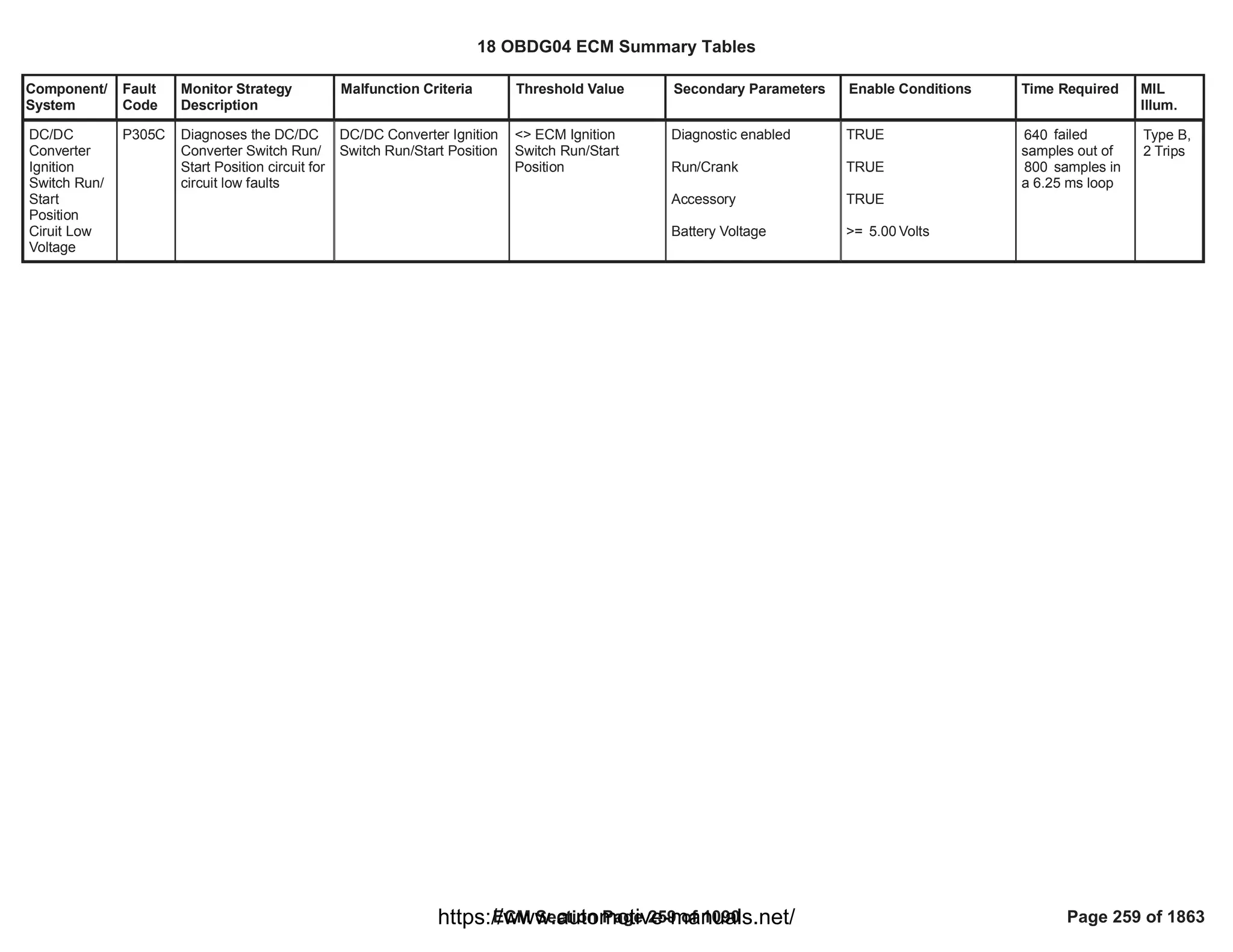
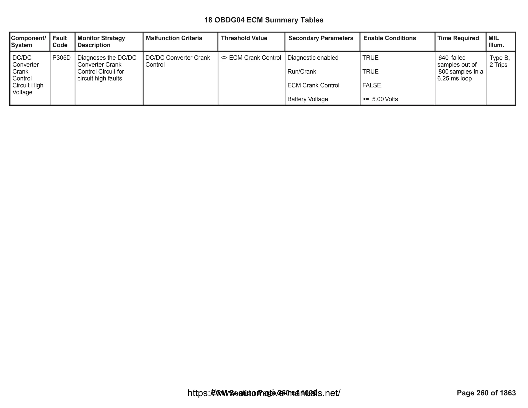

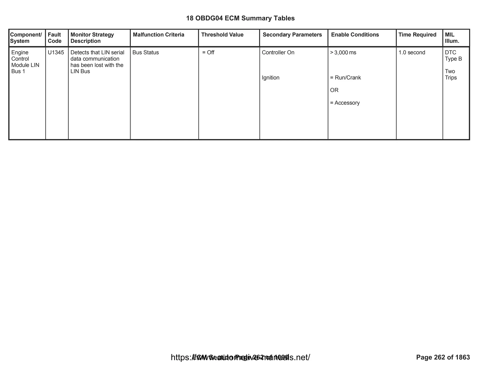
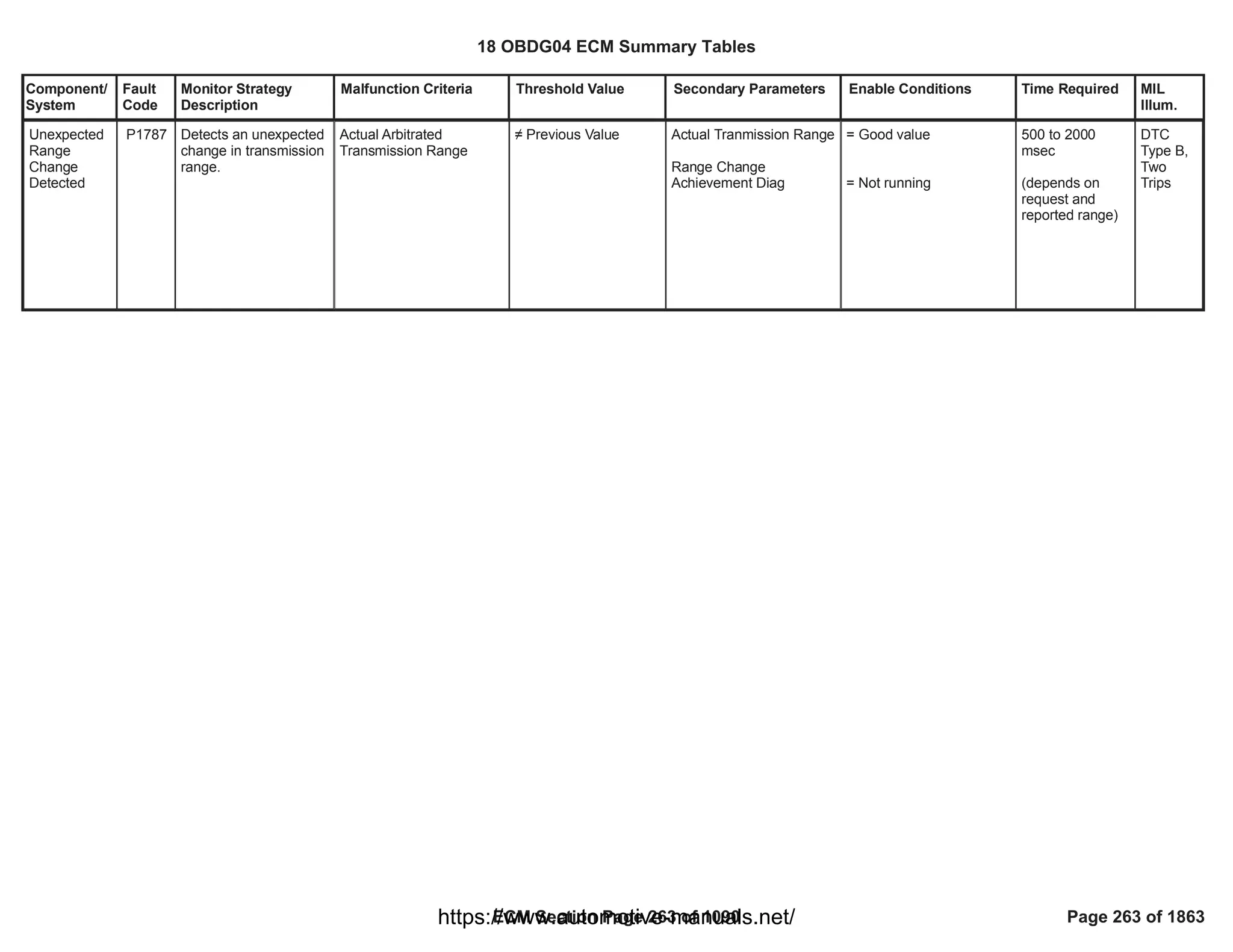
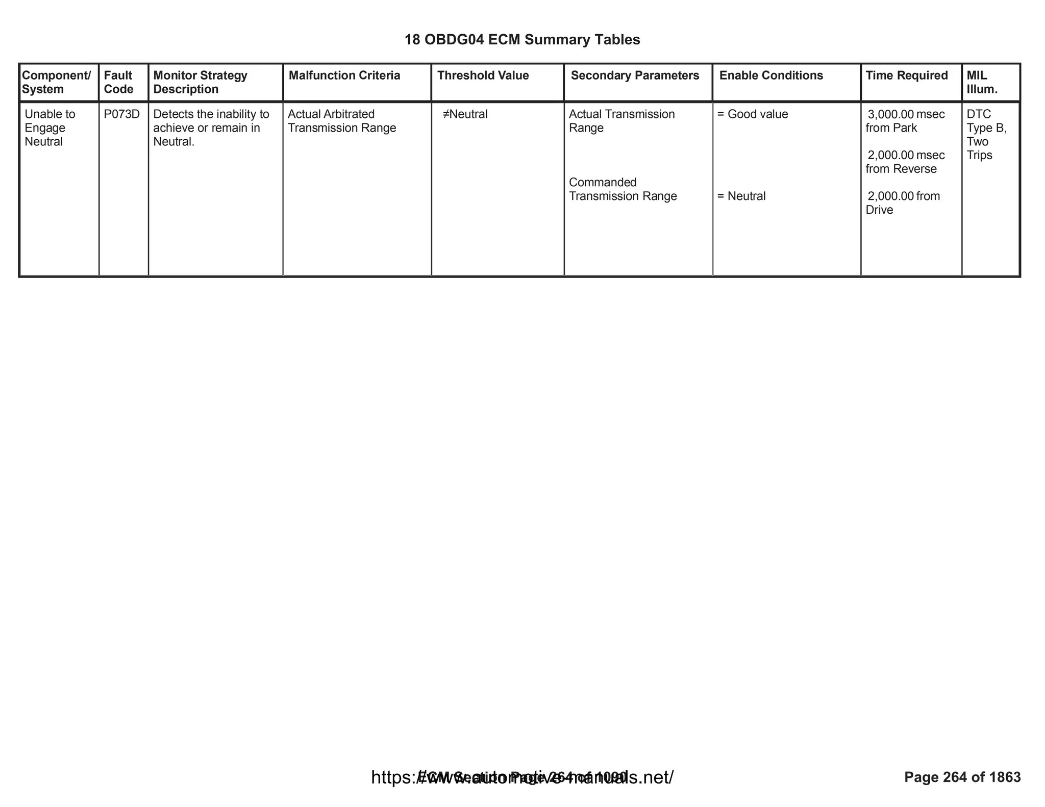
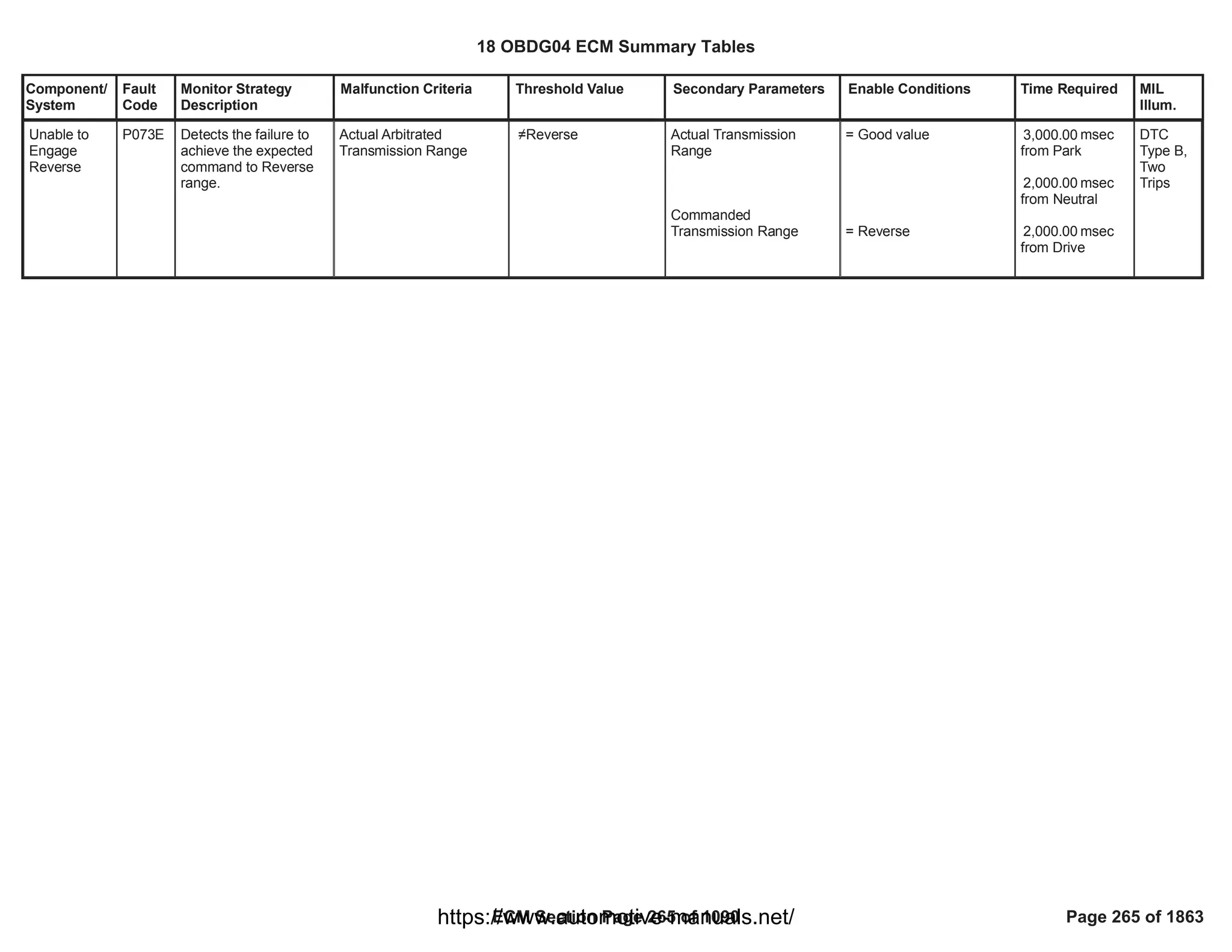
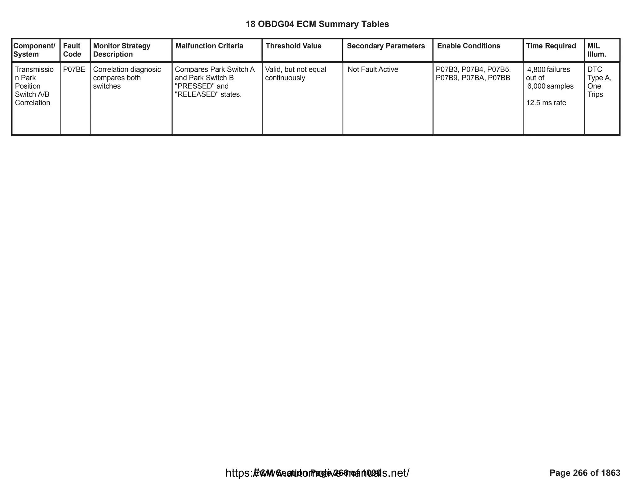
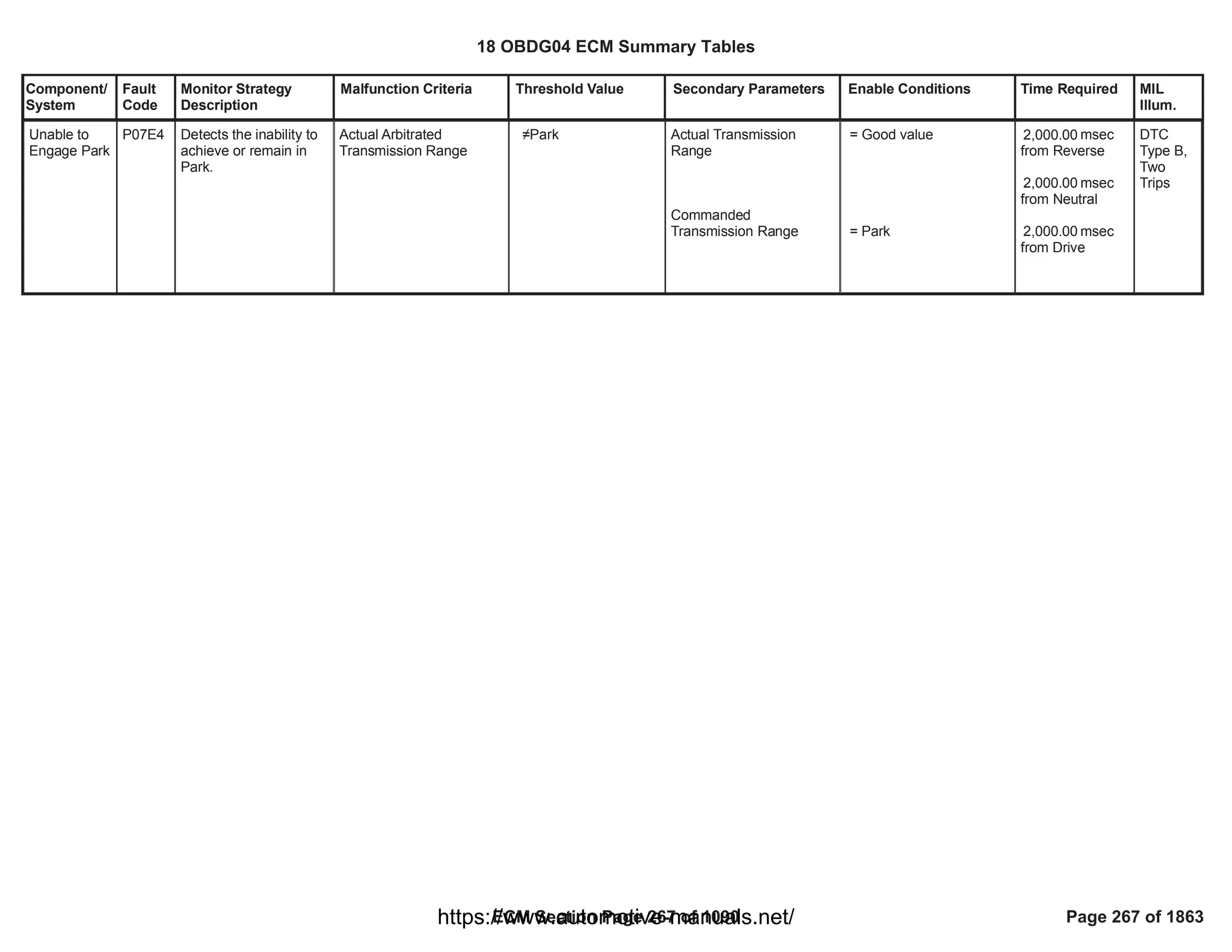

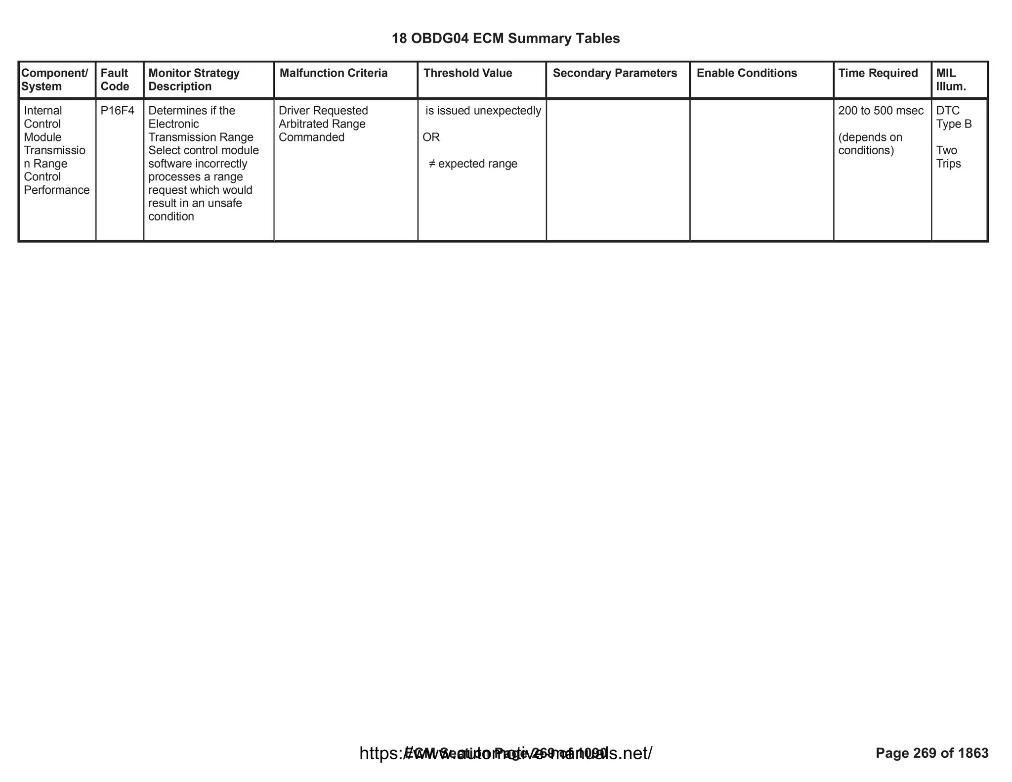
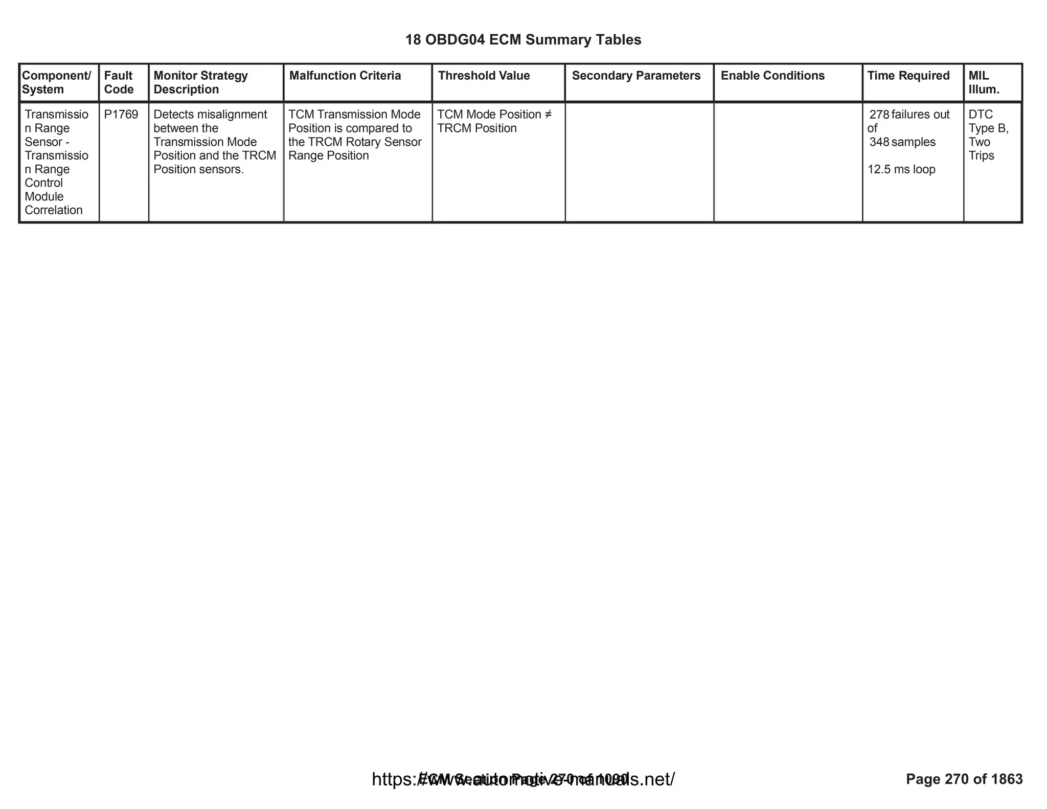
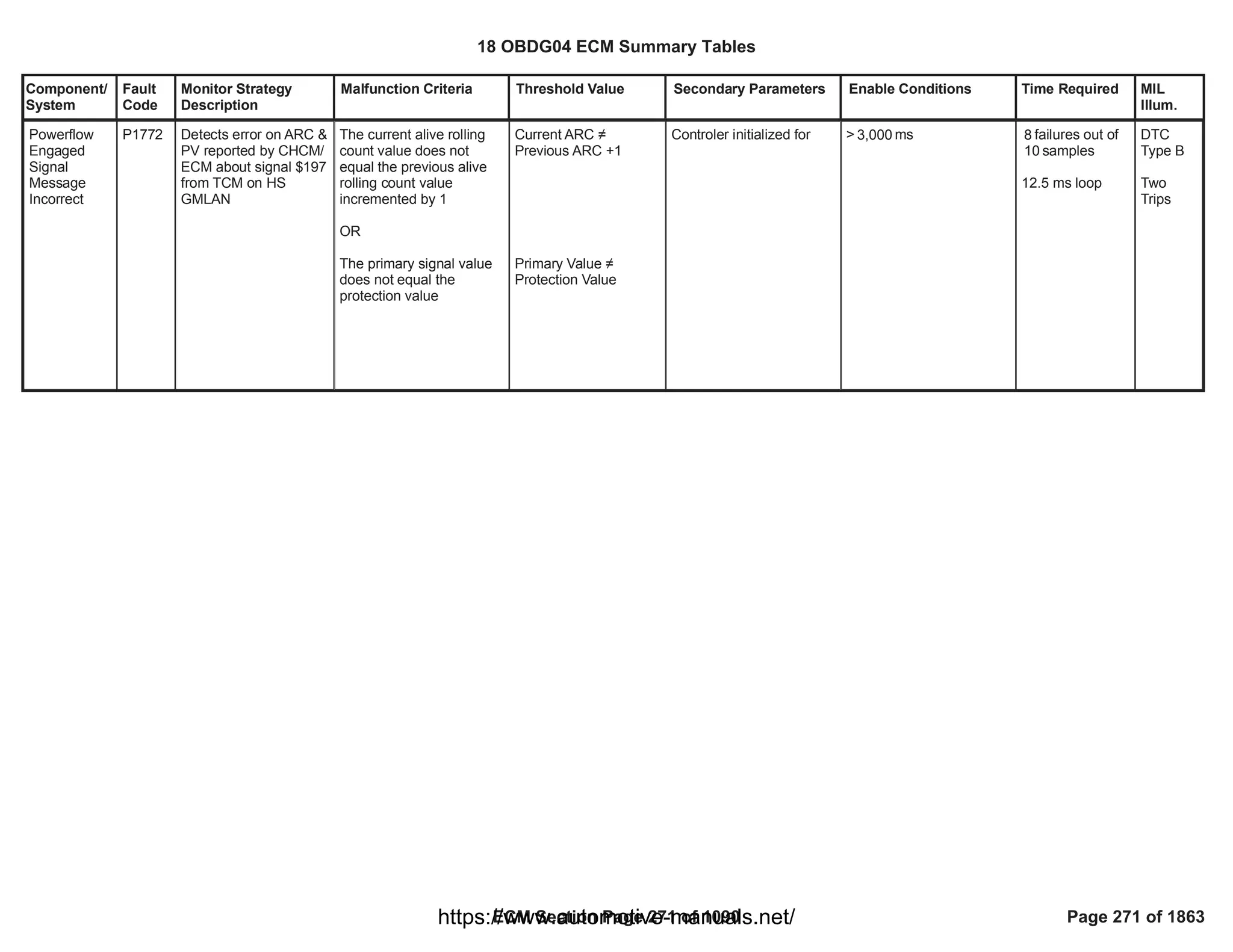
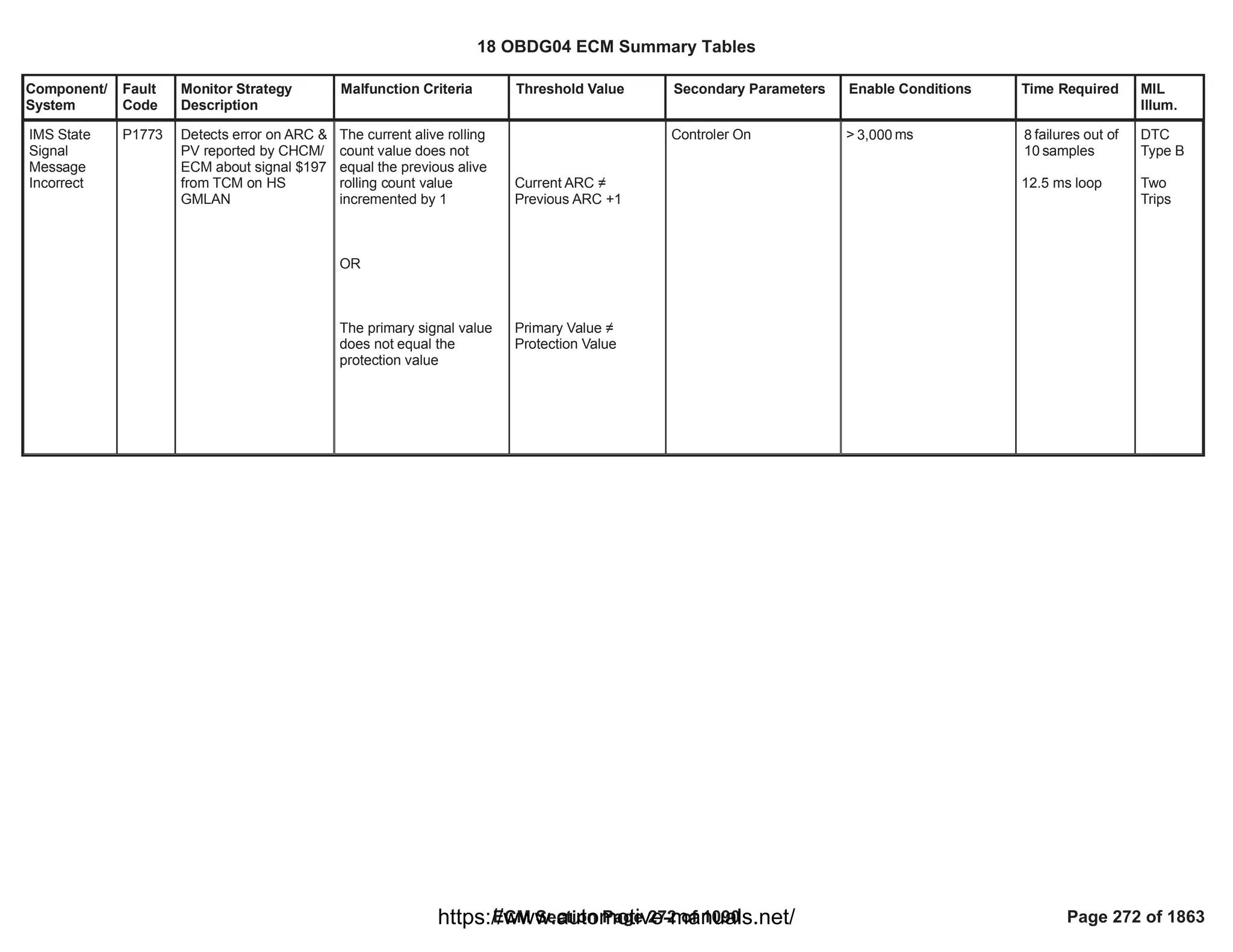
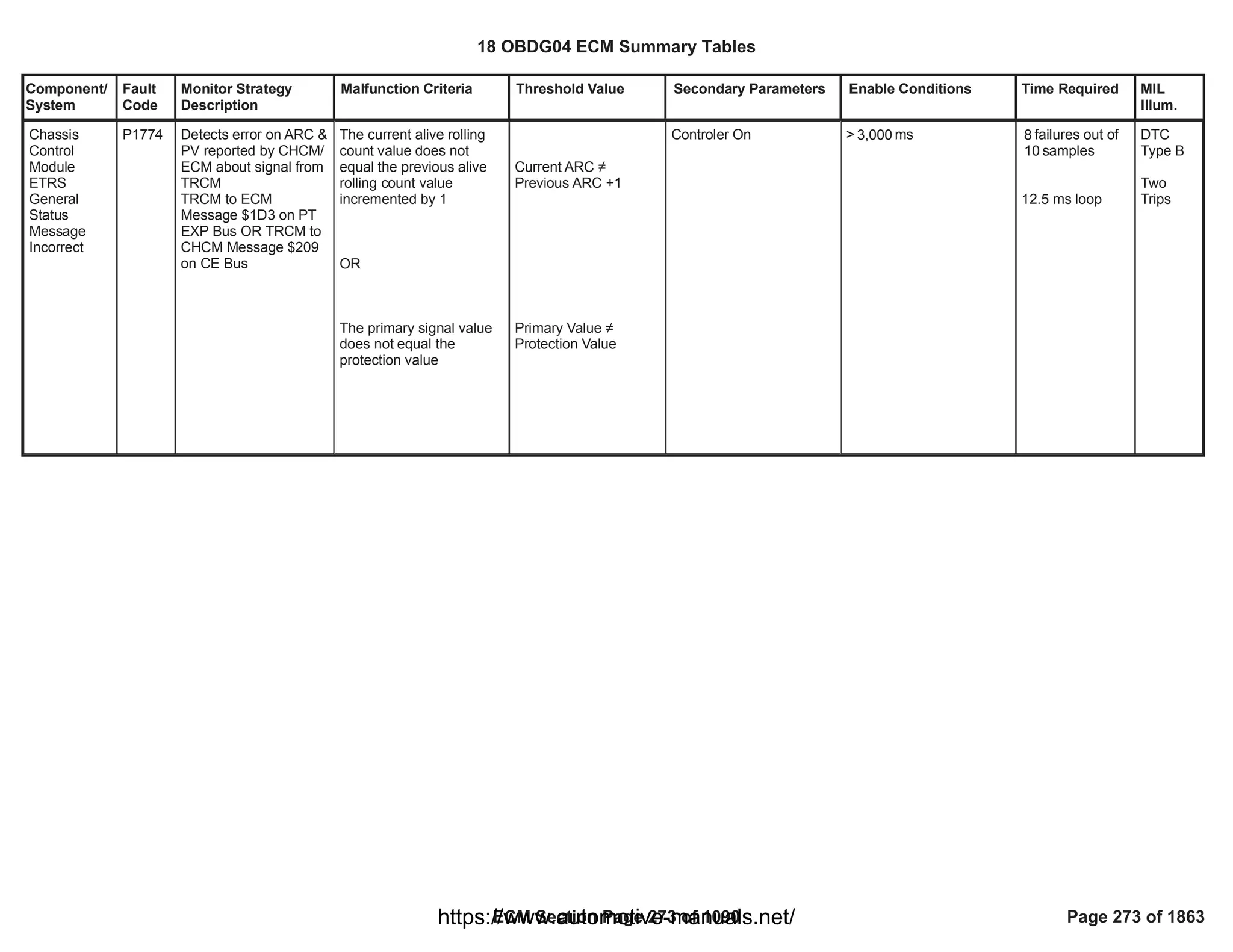
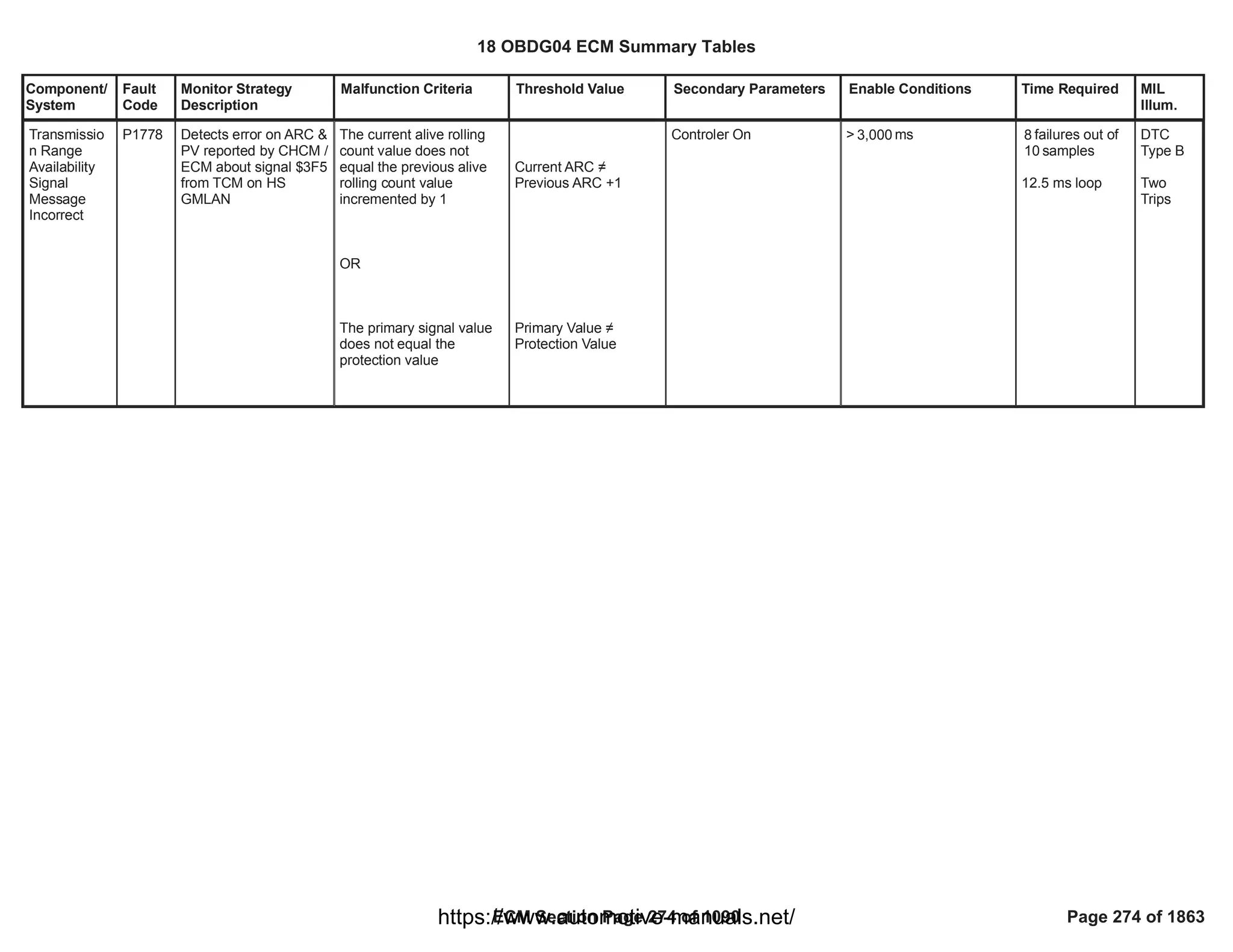
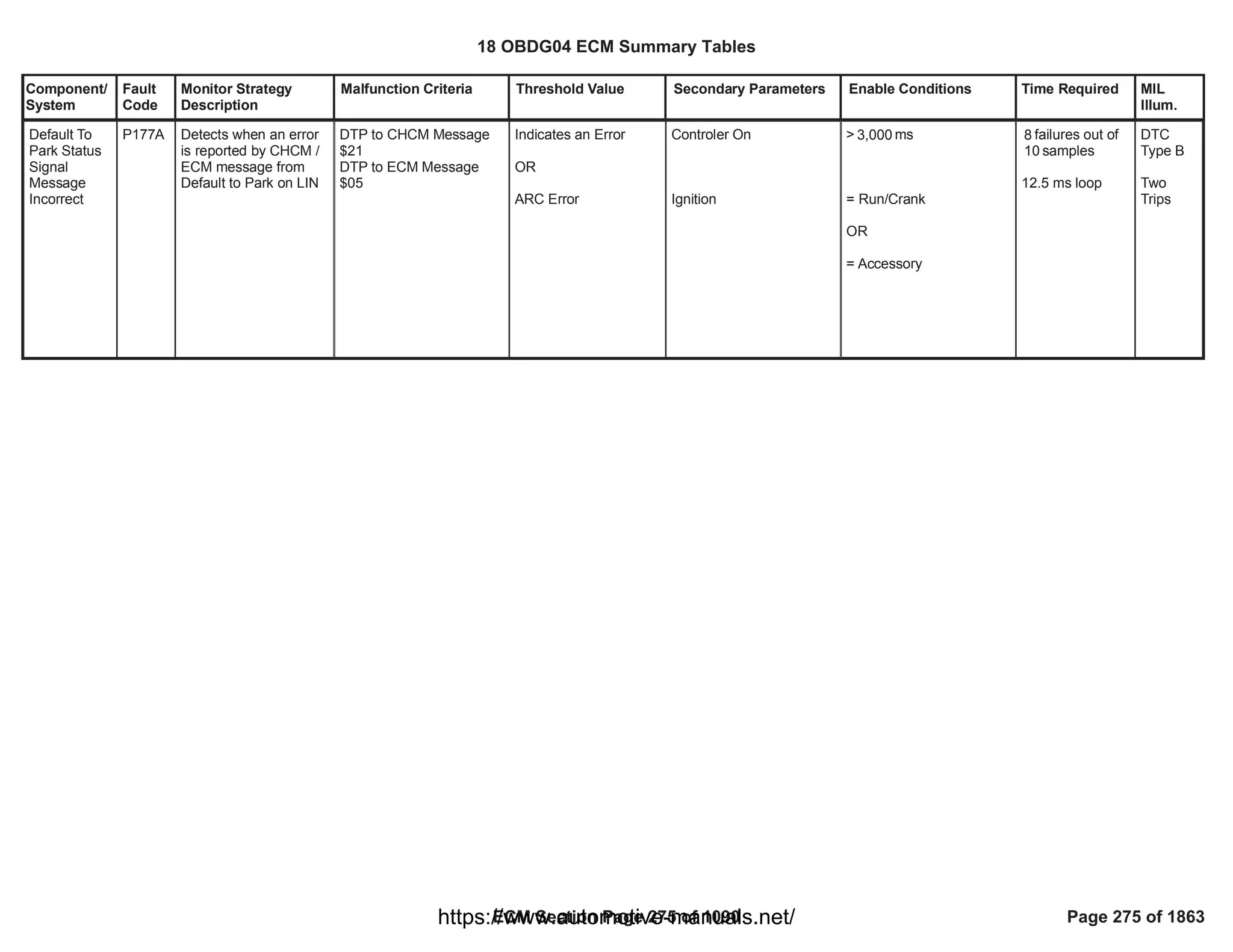
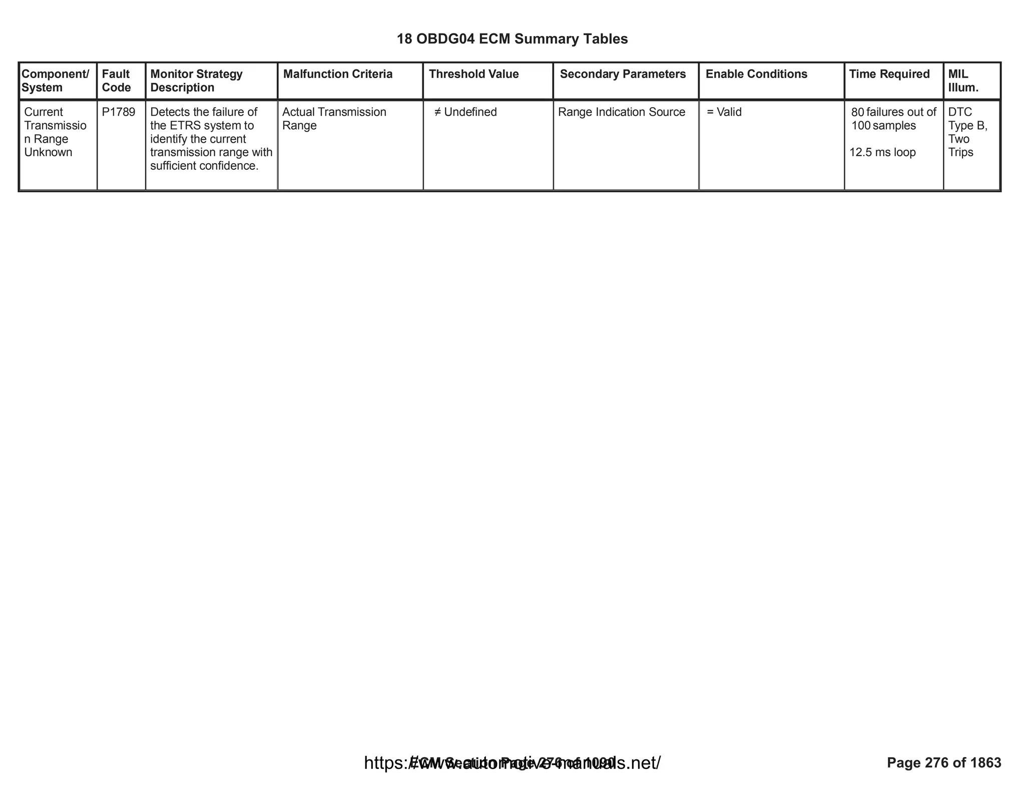
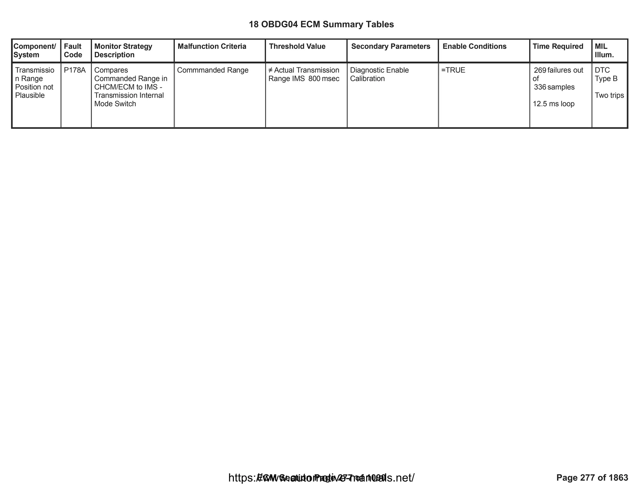
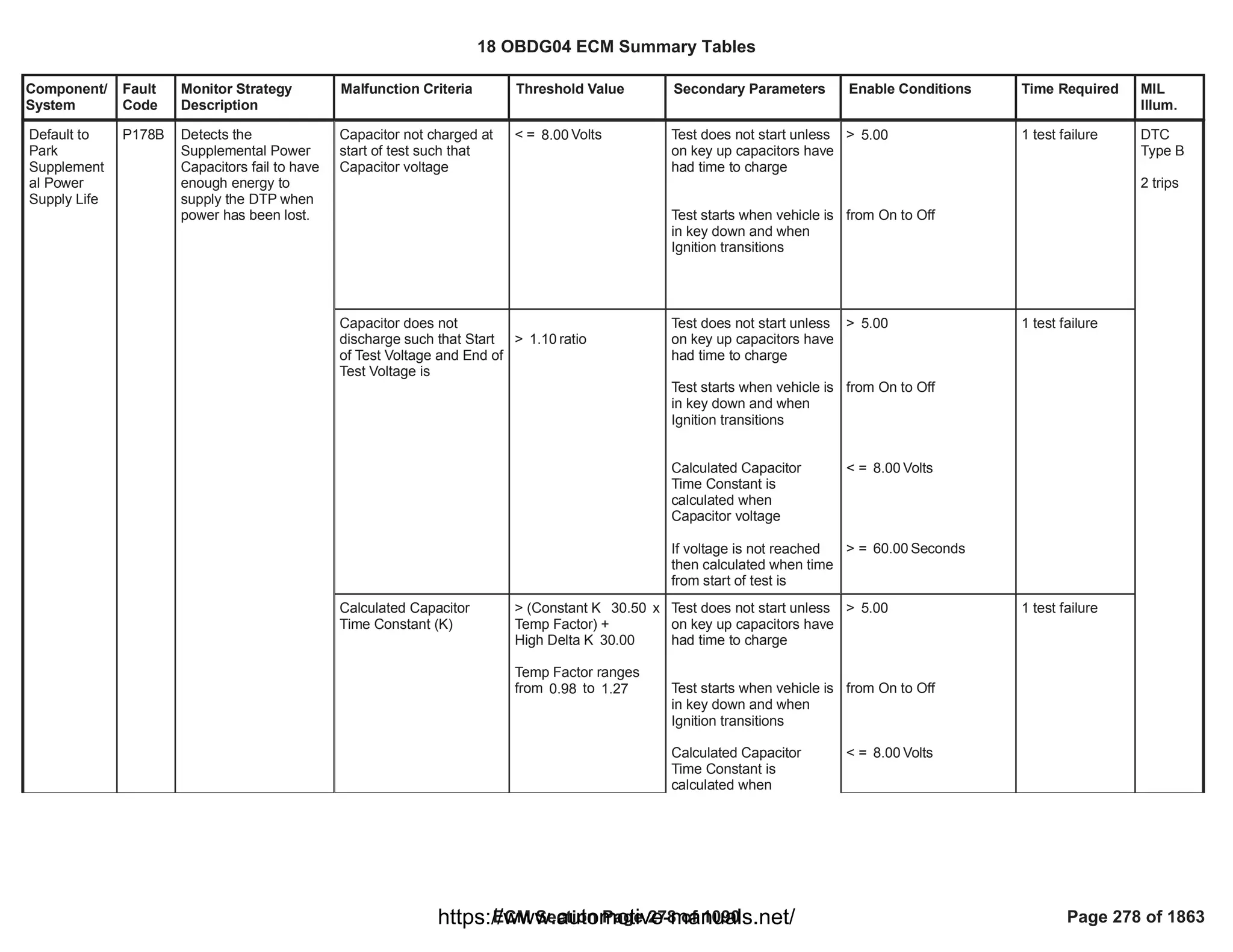

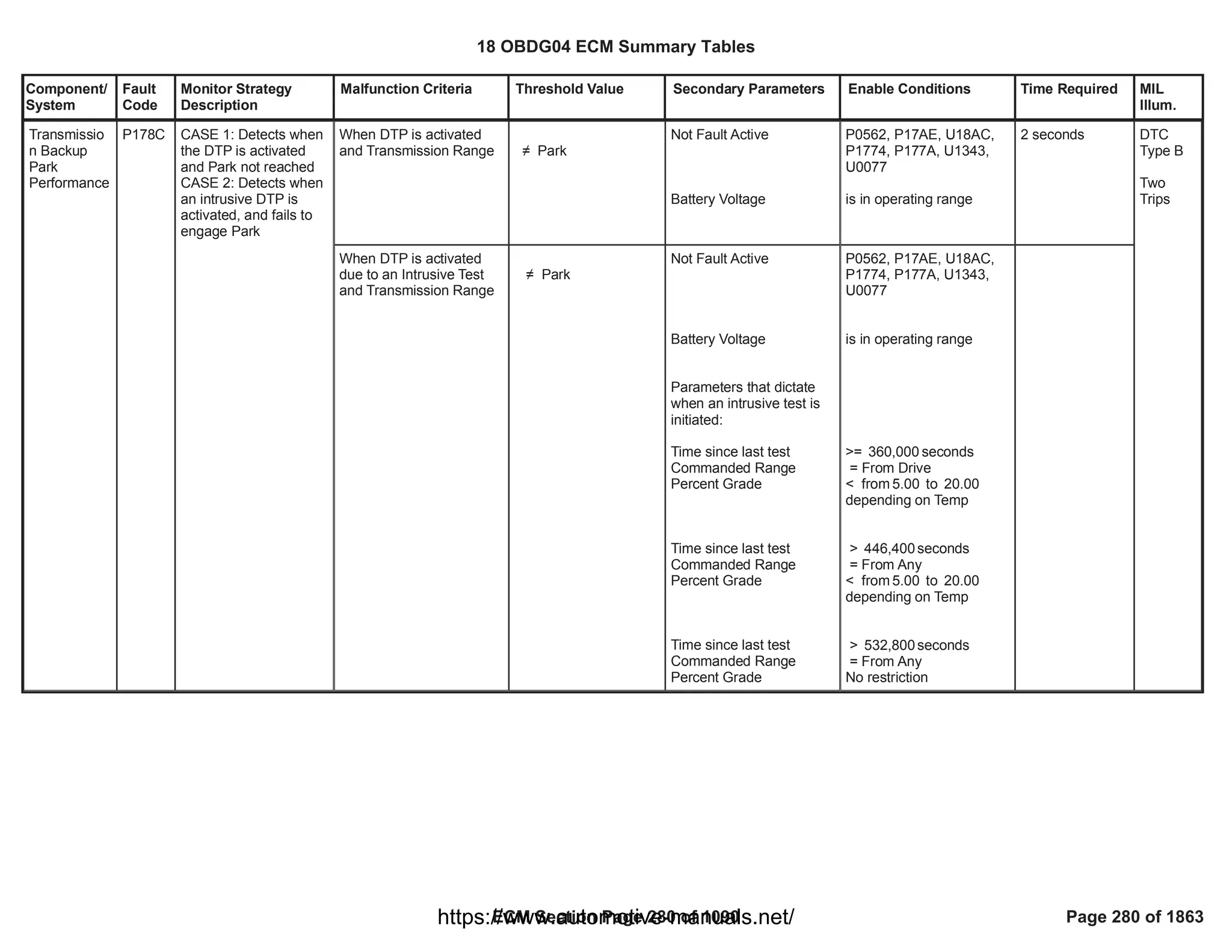
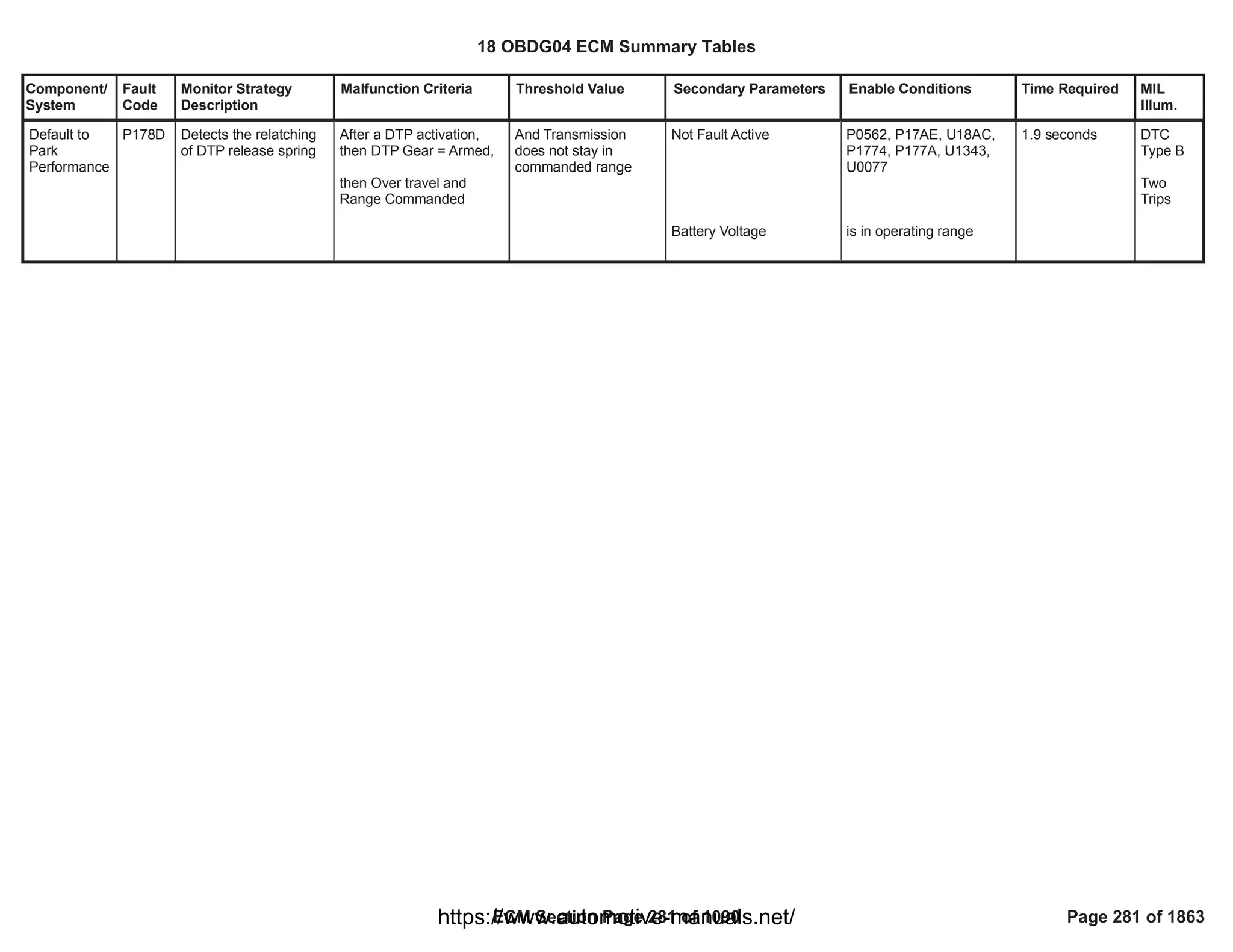
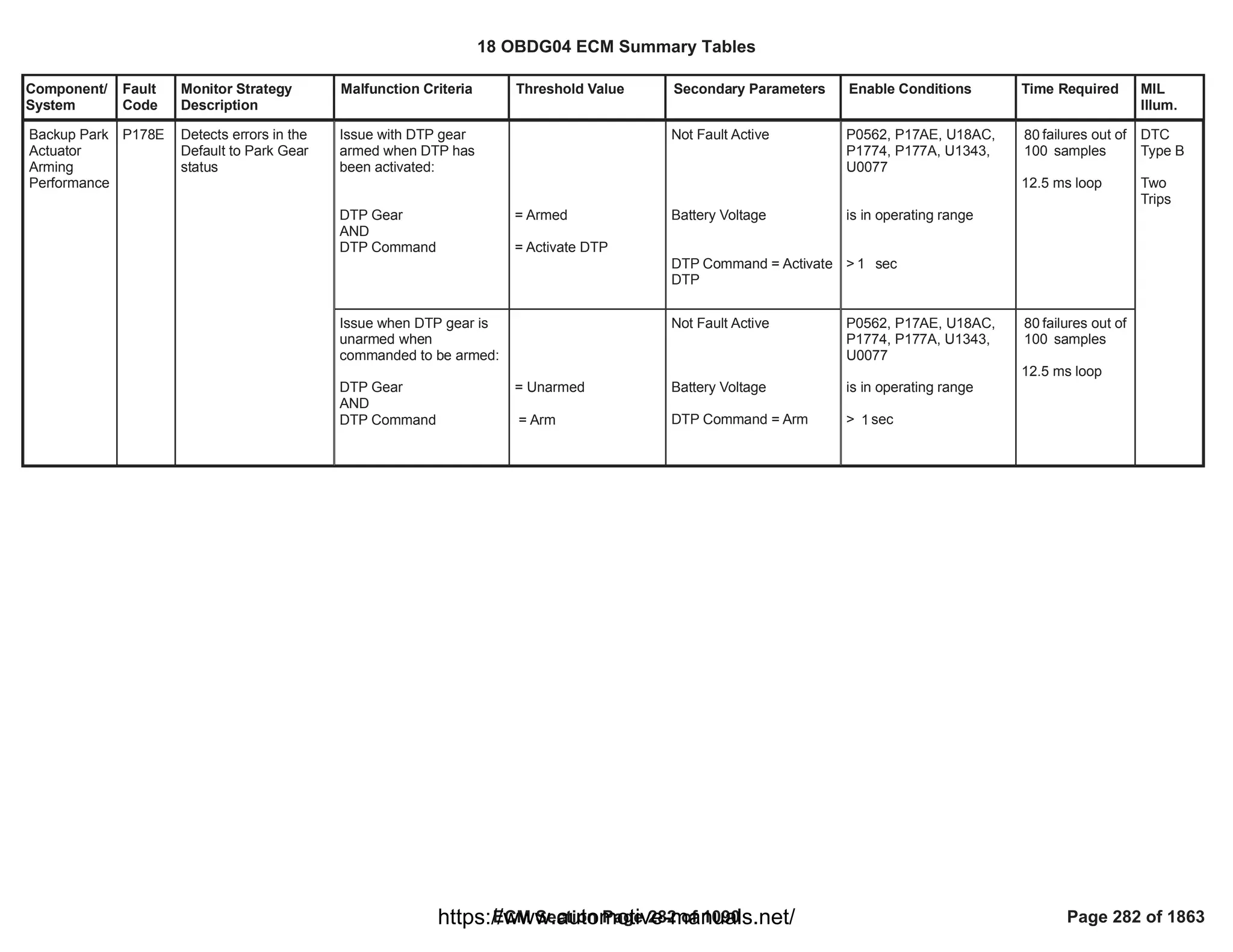

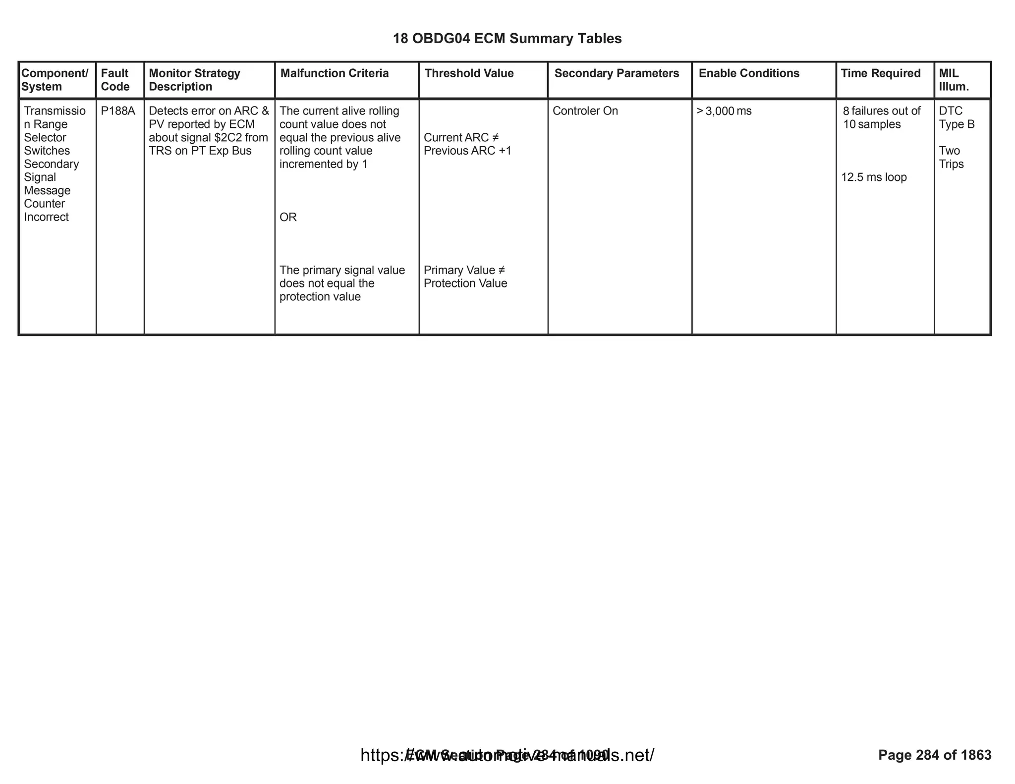
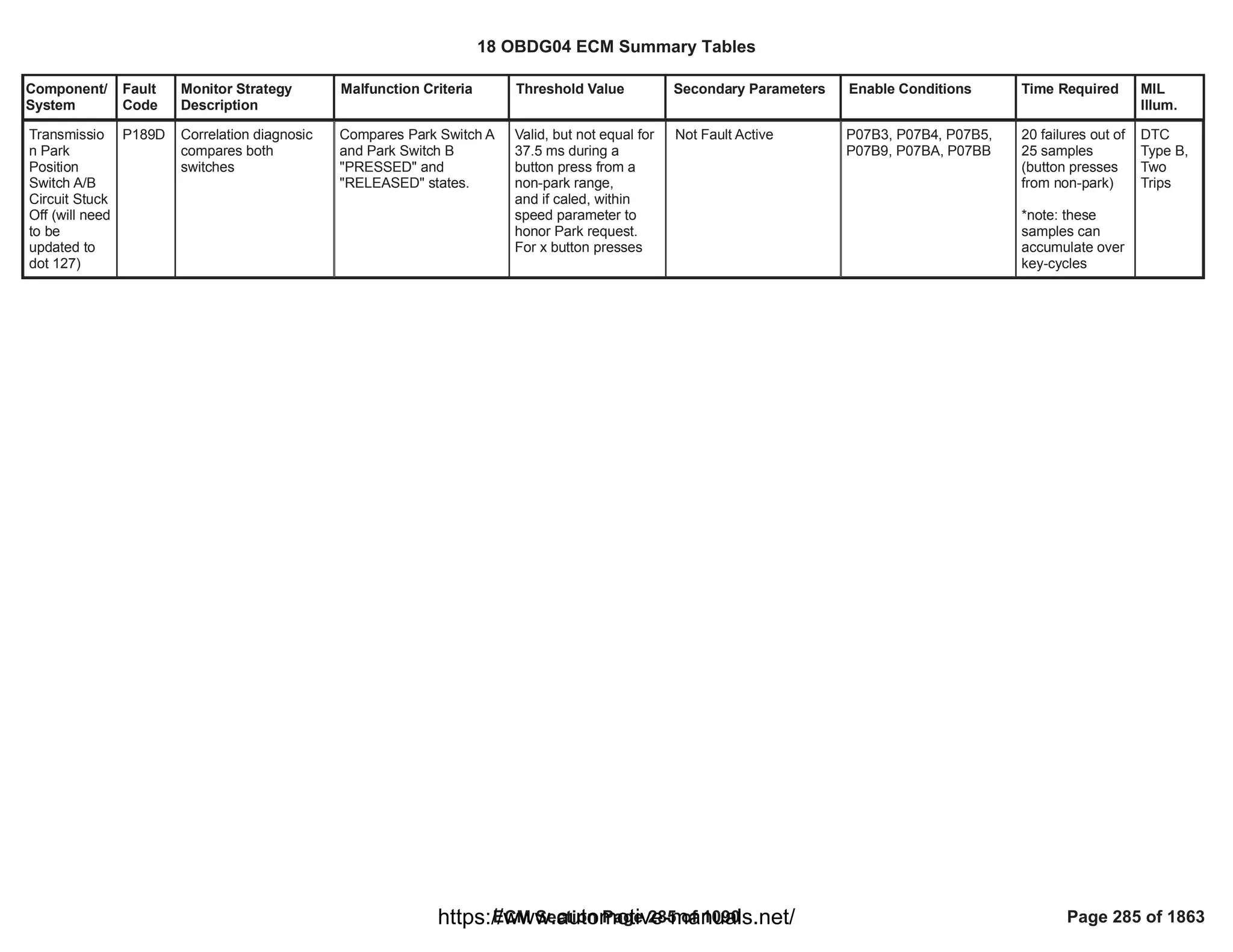


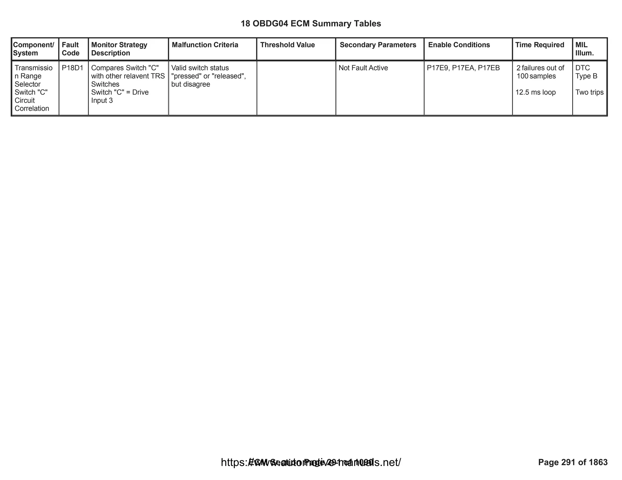


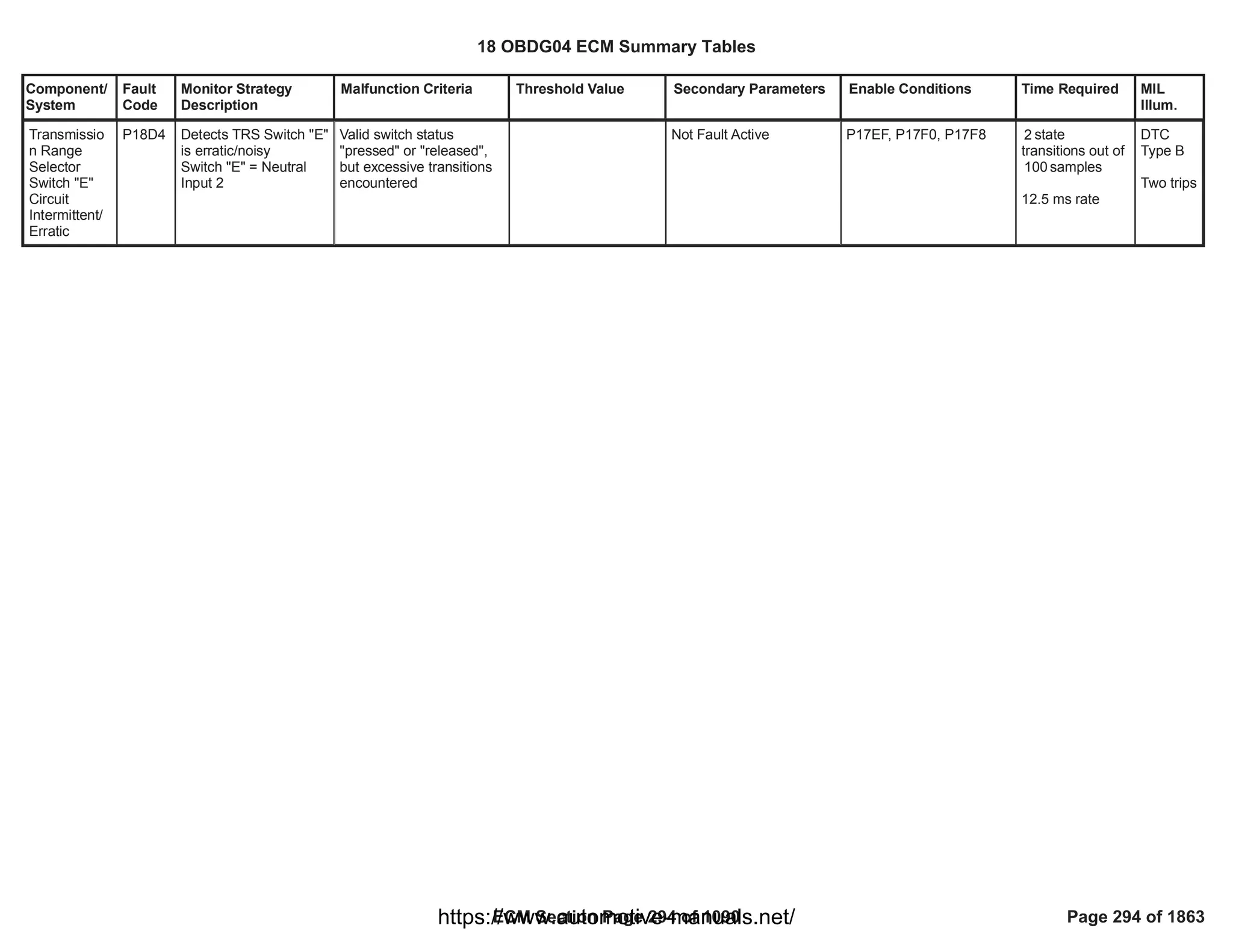


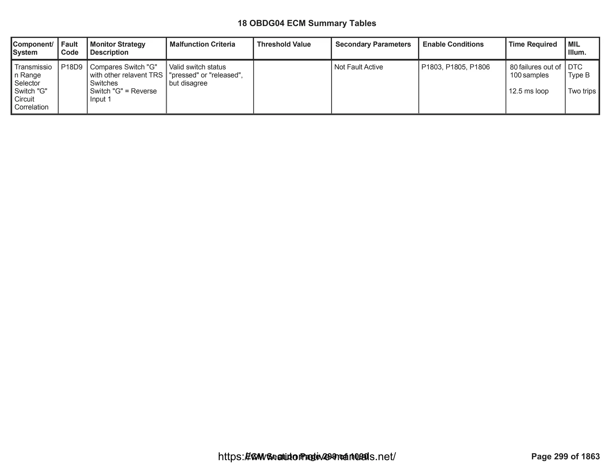


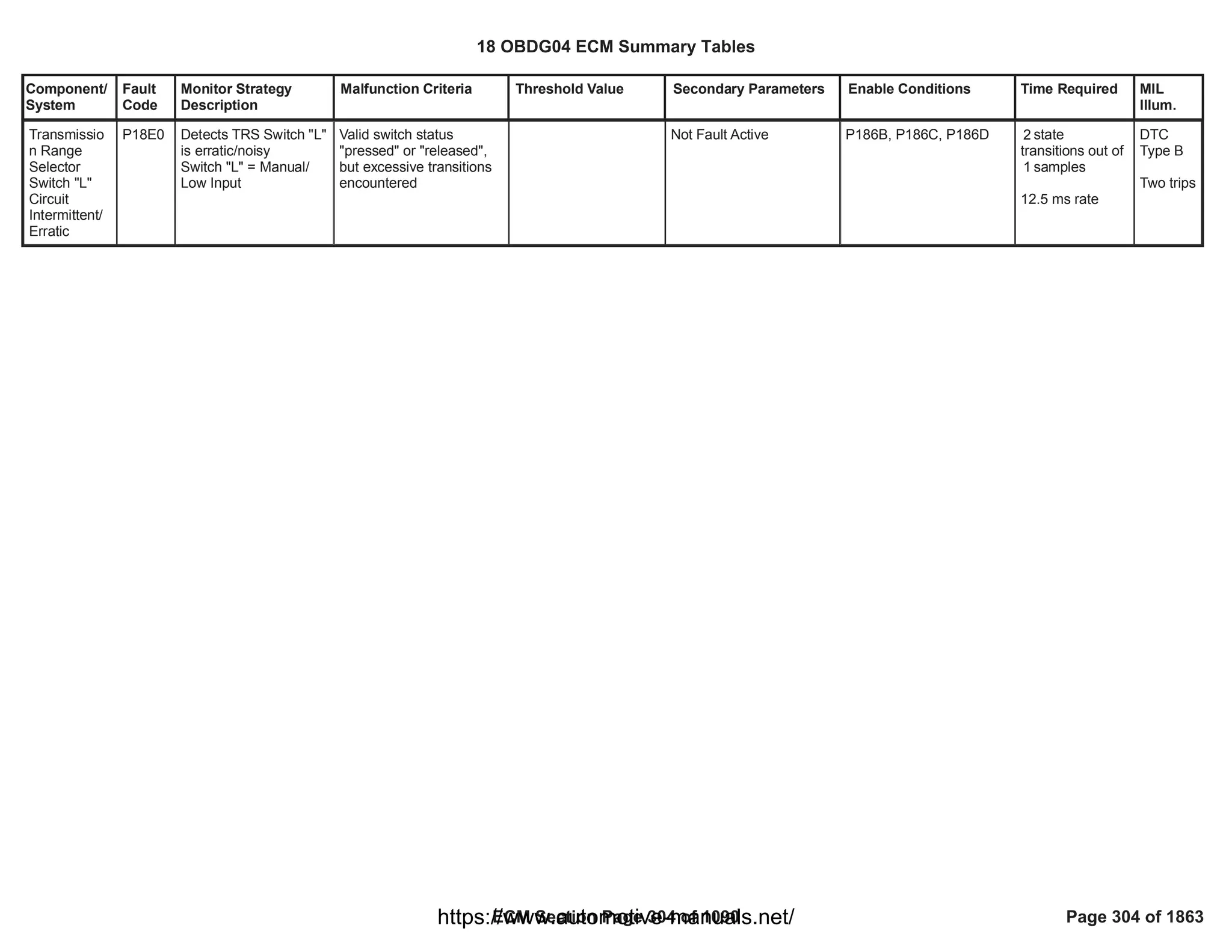

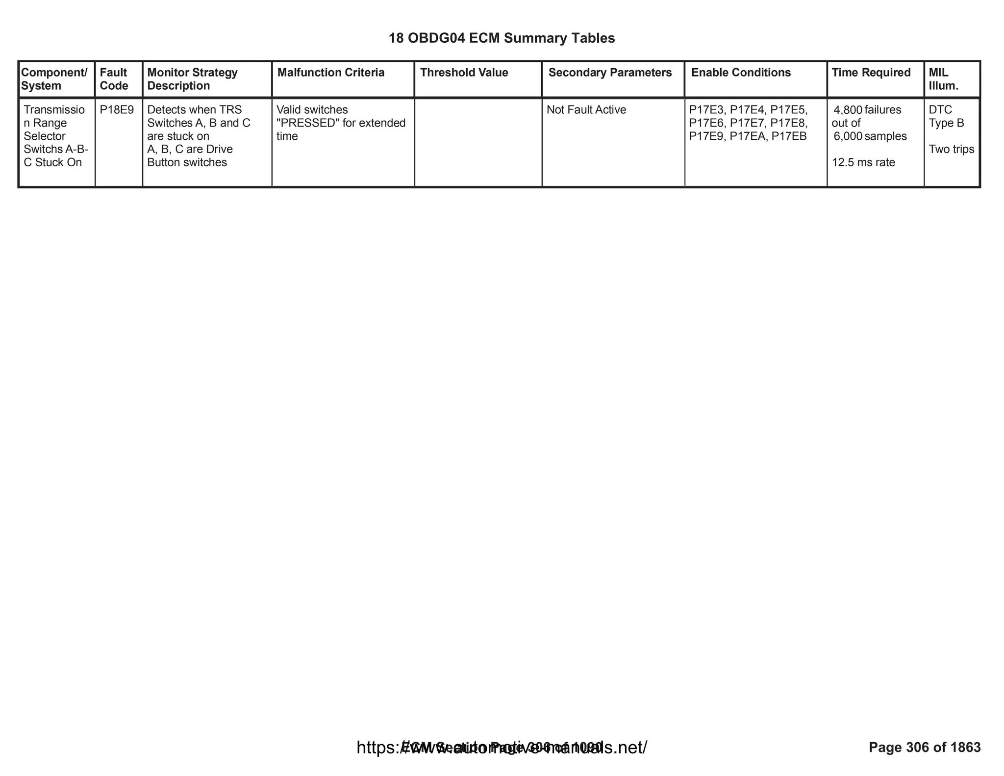

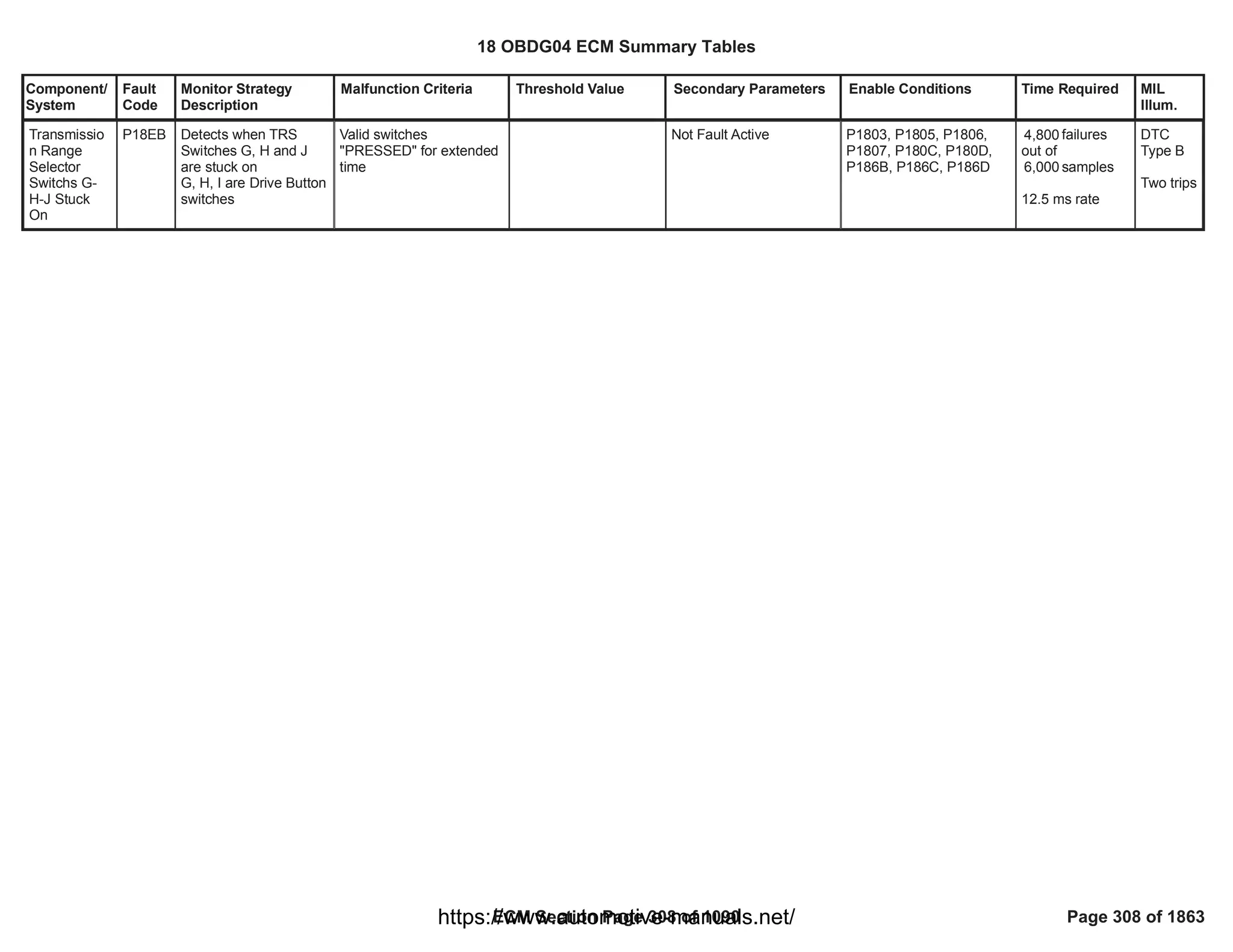
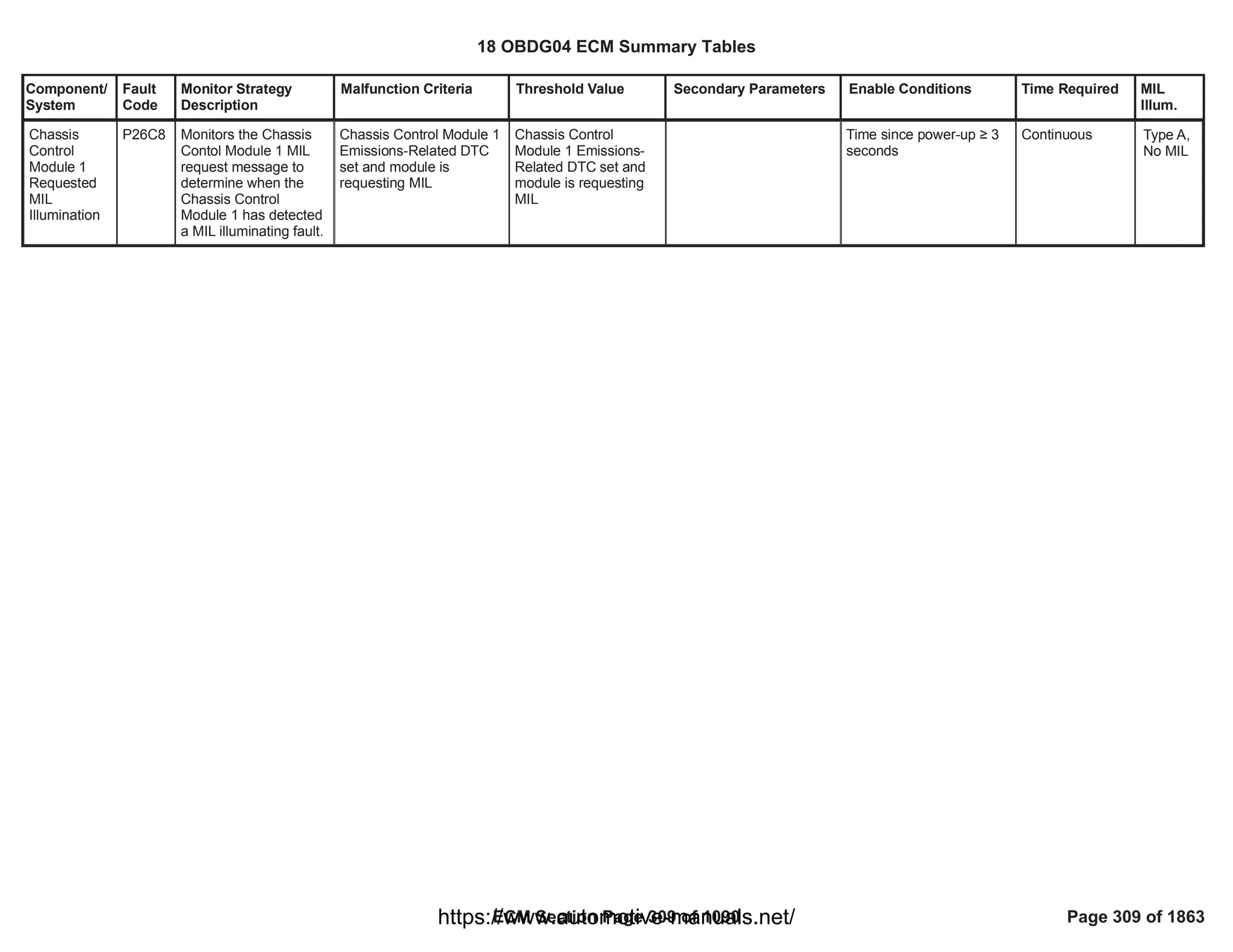
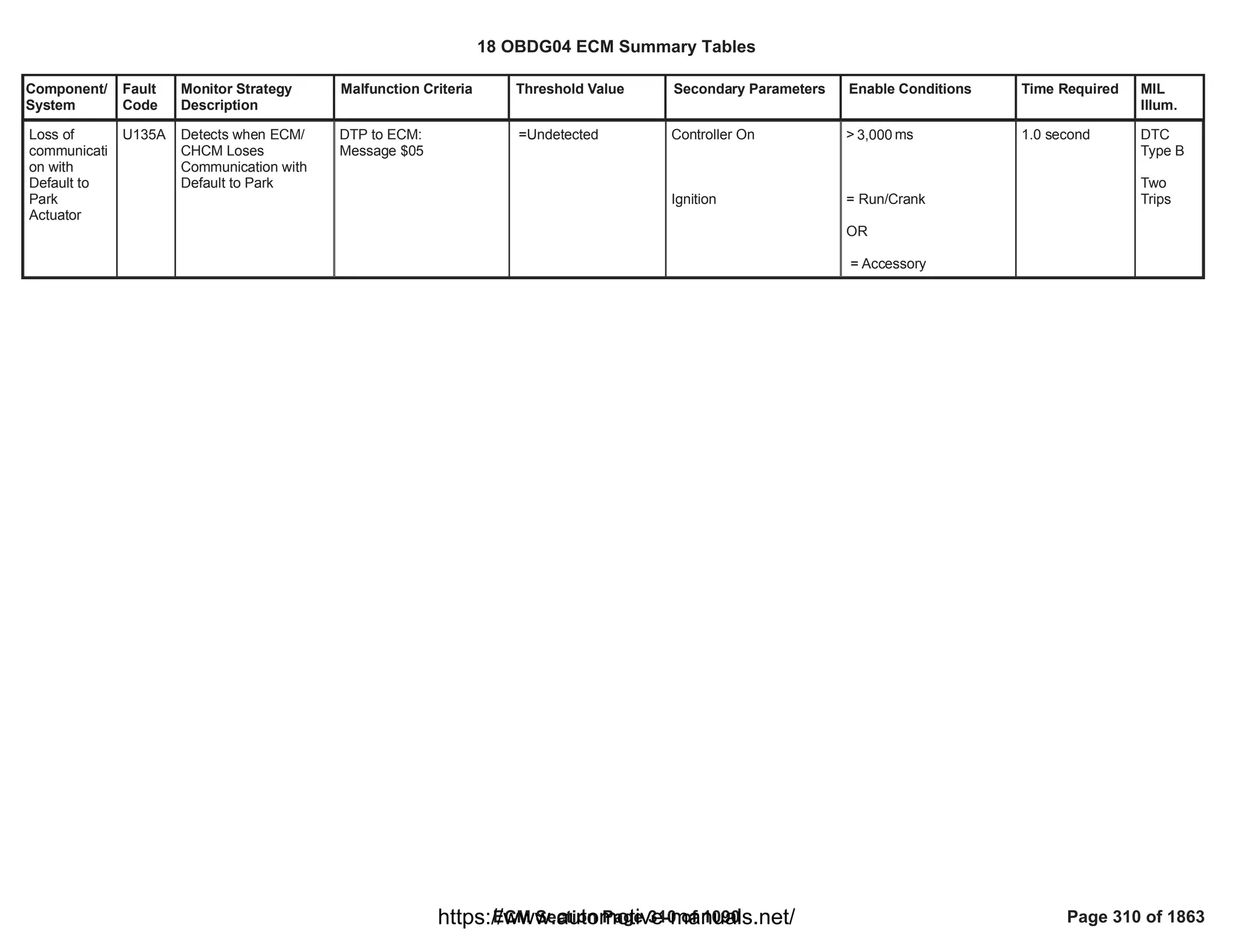
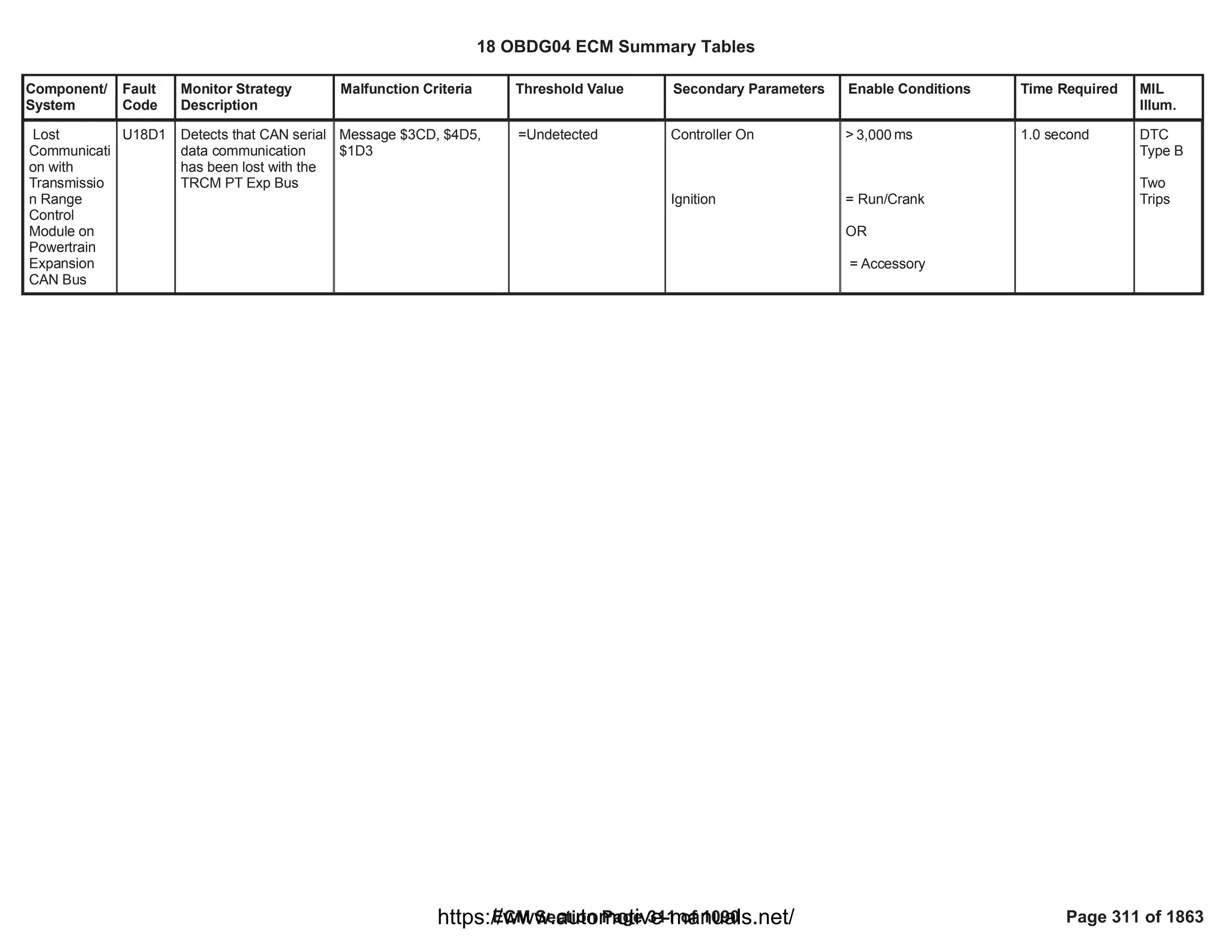
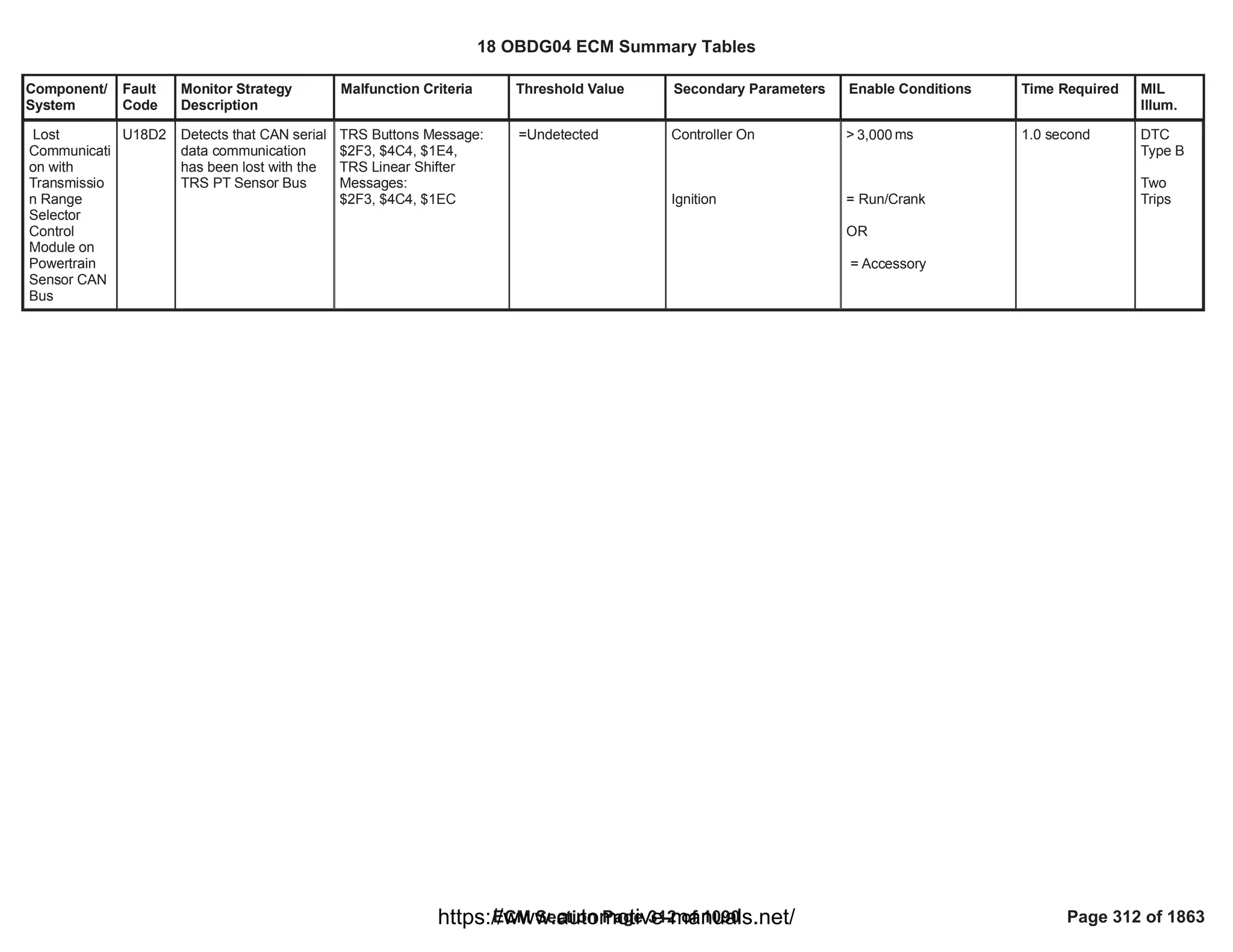
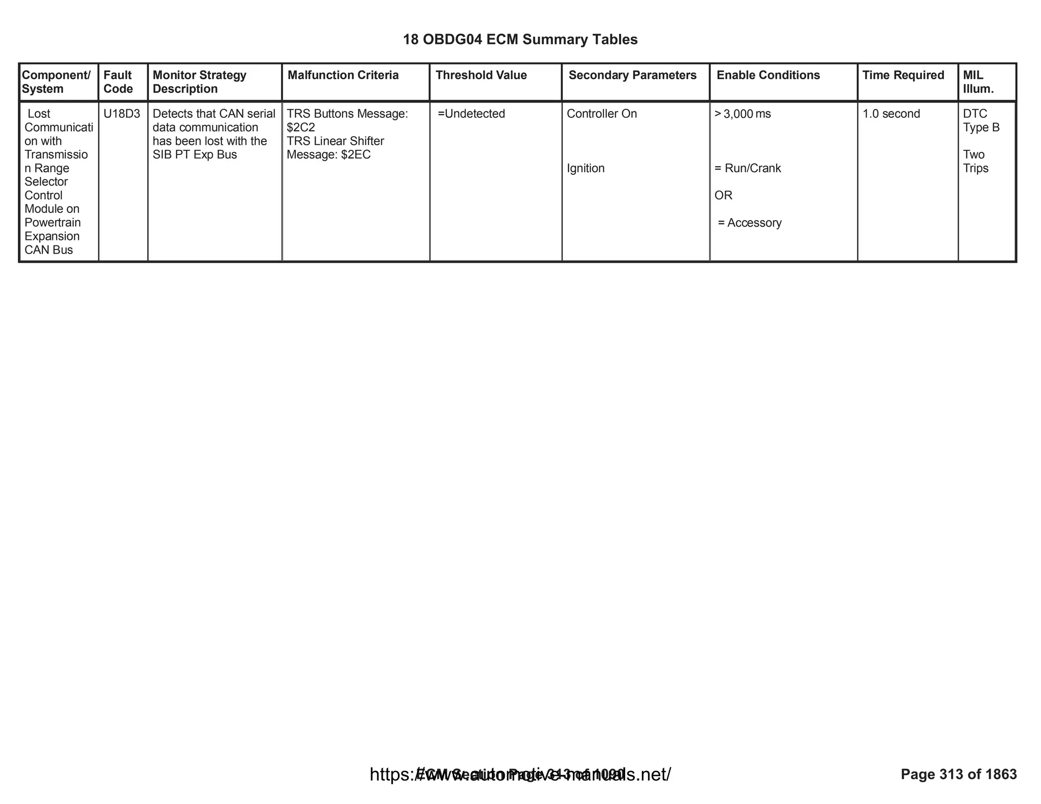
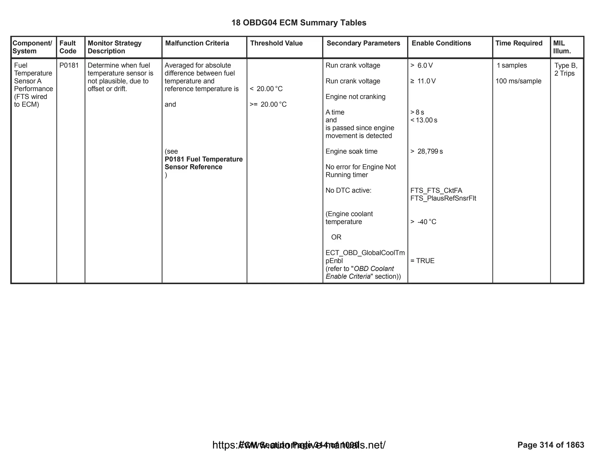
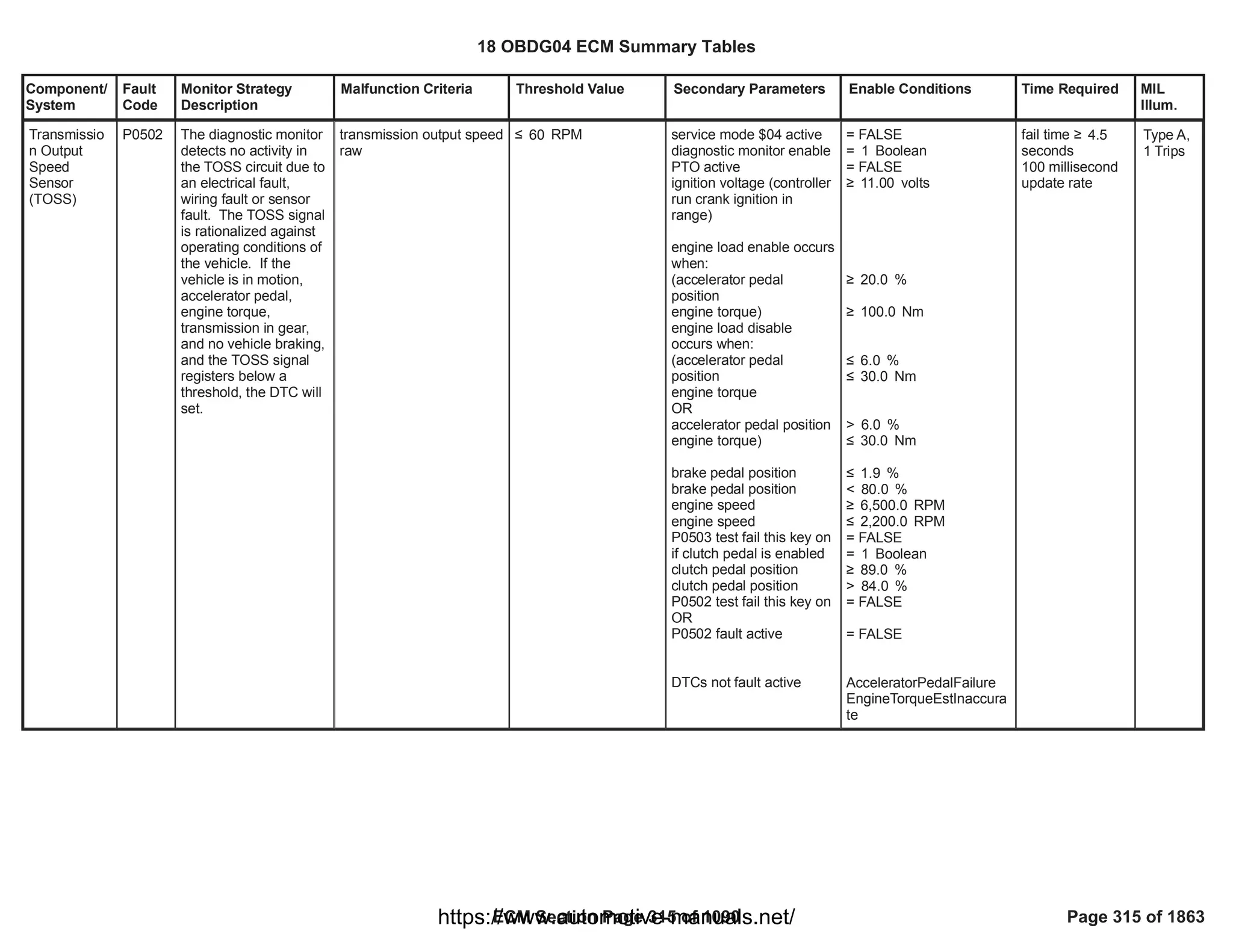
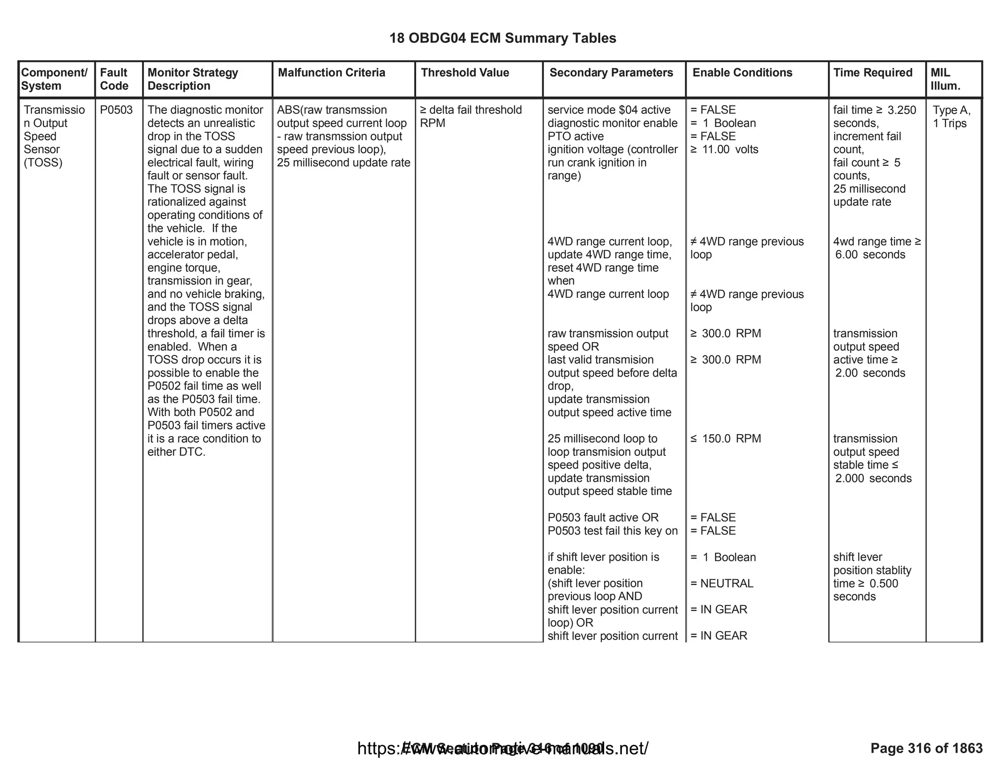
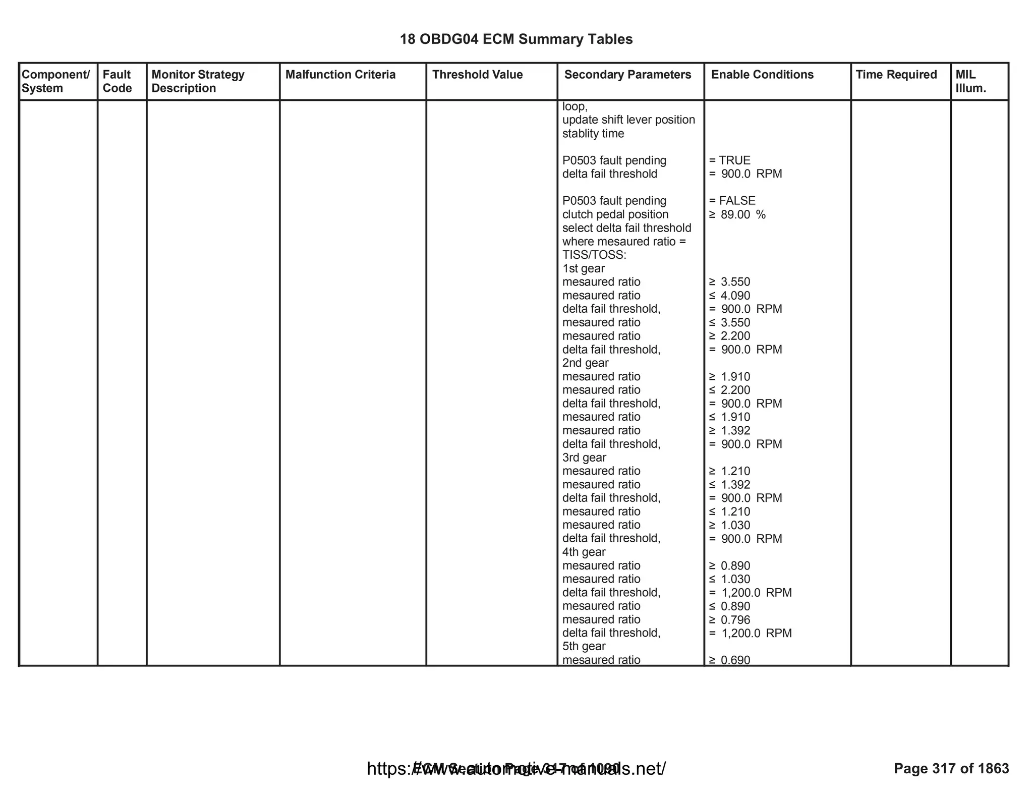
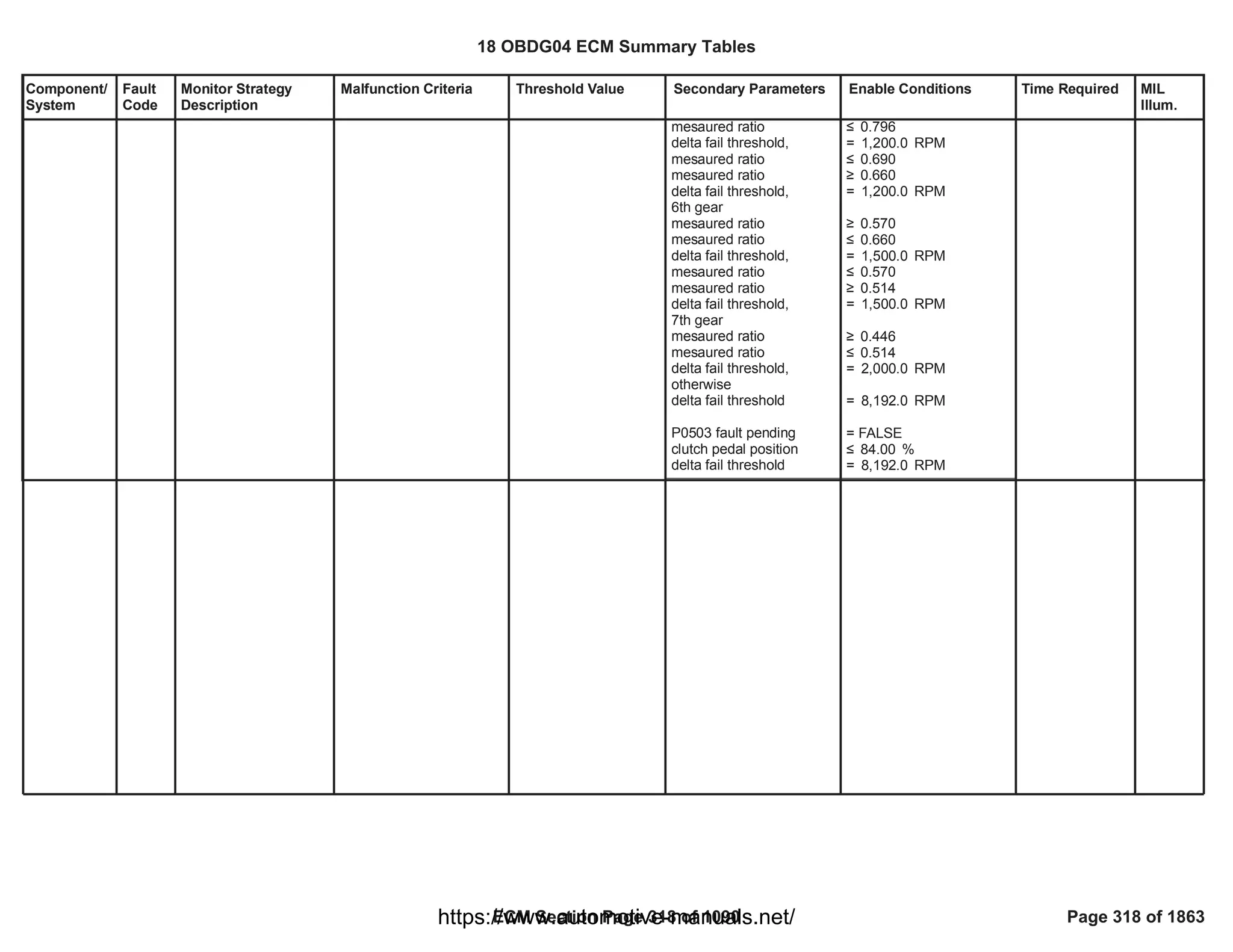
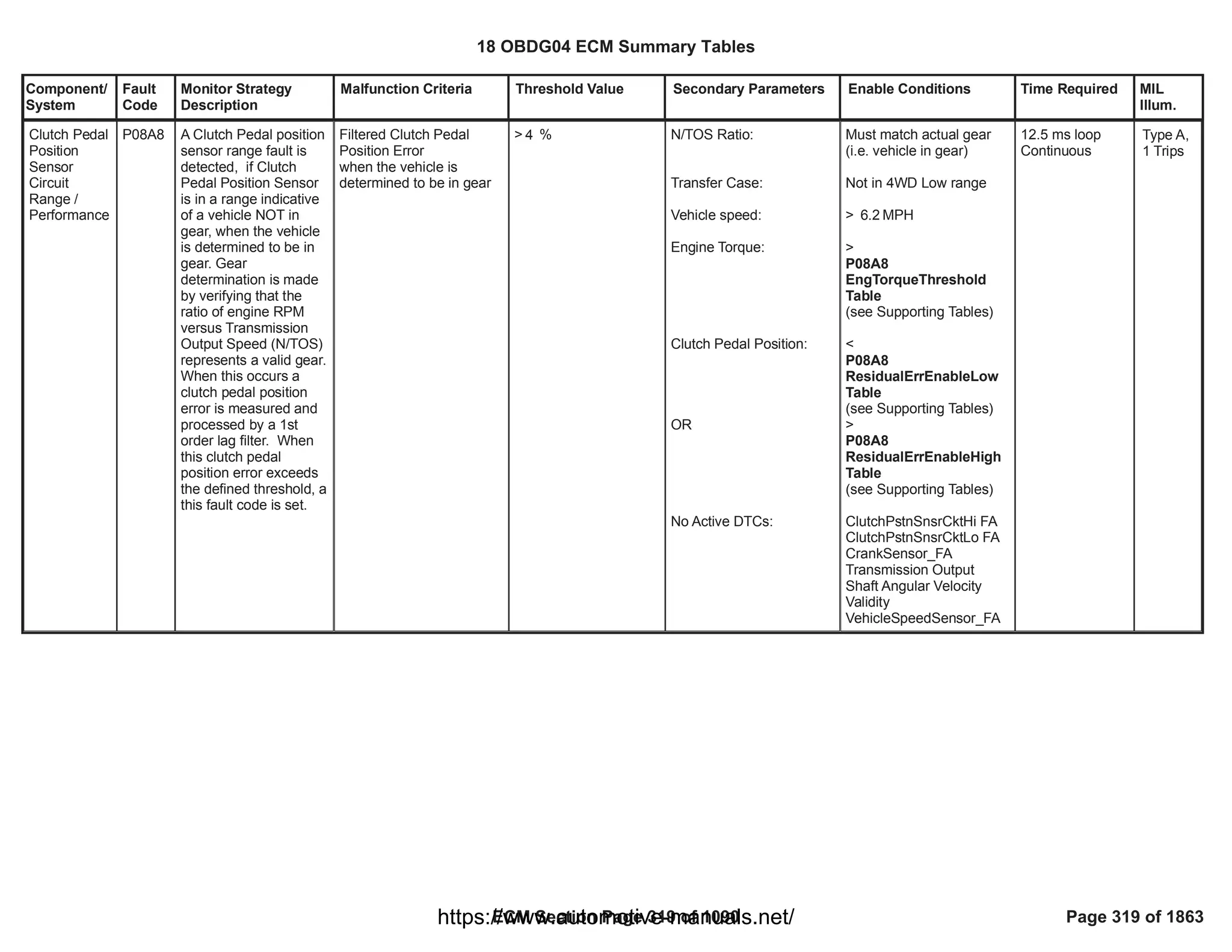
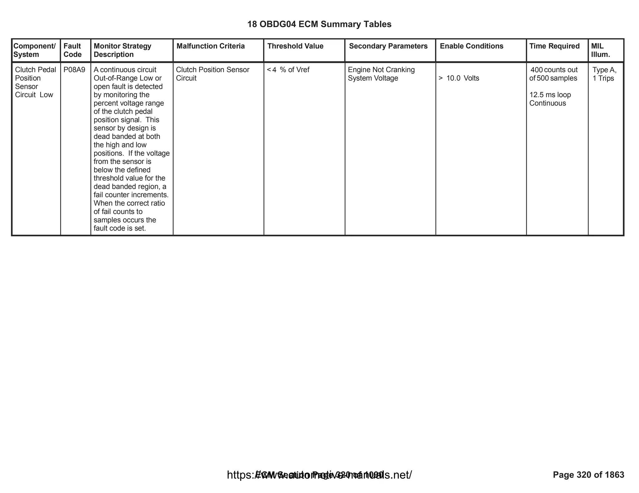
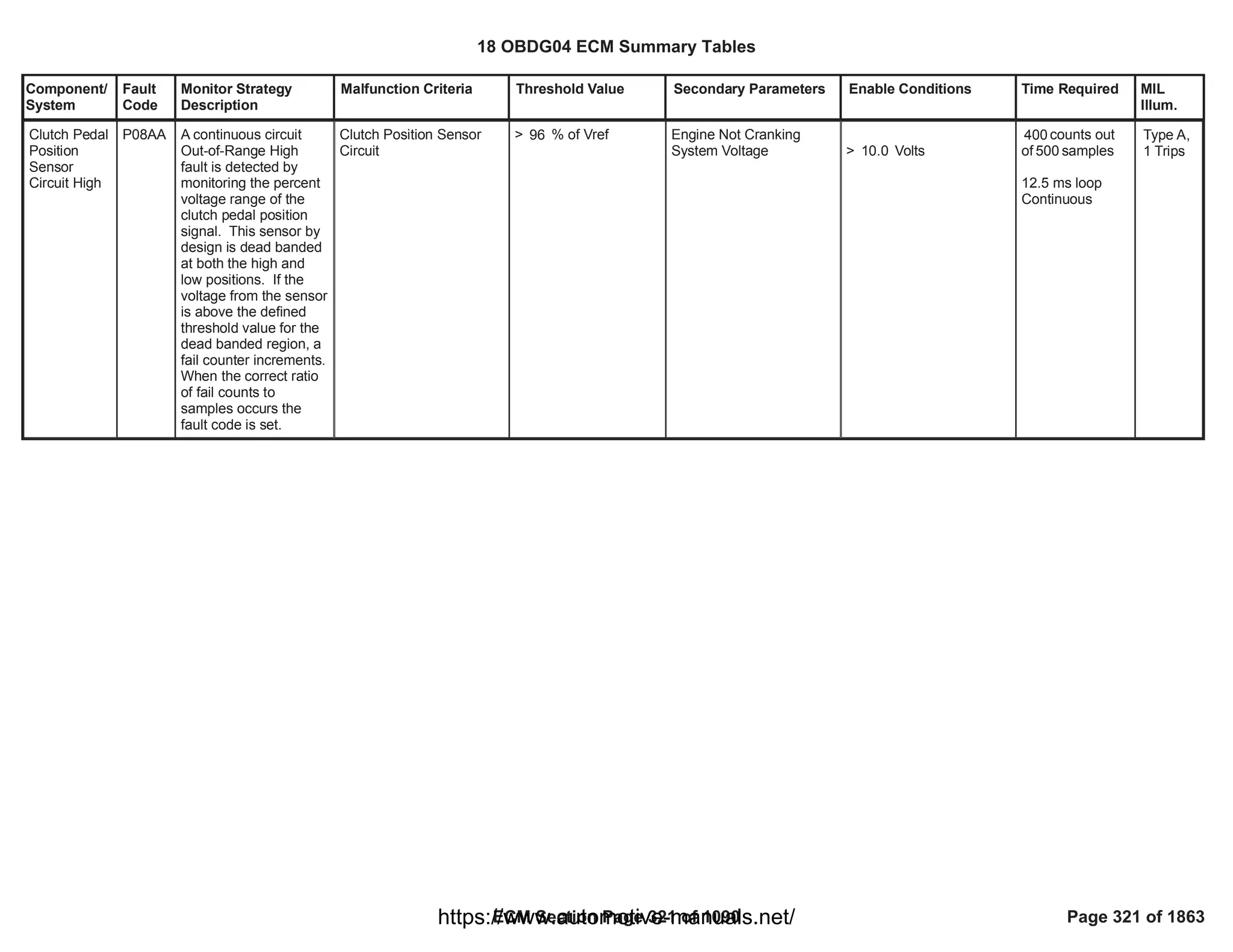
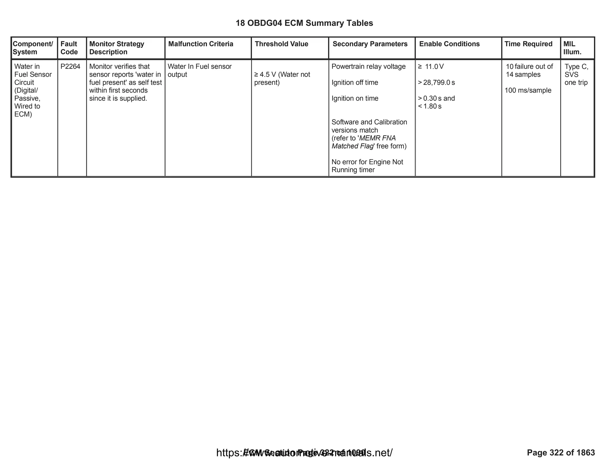
![Component/
System
Fault
Code
Monitor Strategy
Description
Malfunction Criteria Threshold Value Secondary Parameters Enable Conditions Time Required MIL
Illum.
Fuel Pump
Secondary
Circuit Low
[FPPM
applications
only]
P0231 This DTC detects if the
fuel pump control
circuit is shorted to low.
Per "smart device"
design guidelines,
Fuel Pump Power
Driver device reports a
Faulted state
enumeration if current
>= 18A [25A for high
performance variants.
FPDCM reports Not
Faulted enumeration if
current < 18A
FPDCM reports
Indeterminate state
enumeration if the
circuit is not being
evaluated during
current decision loop
due to other conditions.
Power driver output
current
( Fuel Pump Power
Module Driver Circuit
Ground Short
enumeration)
Current >= 18.0 A a) Diagnostic Enabled
b) Fuel Pump Control
Enable command
c) Fuel Pump Control
Enable time [FAFR FPPM
GshtDlyThr]
d) System Voltage
e] FPDCM Driver Status
Alive Rolling Count
Sample Faulted
f] Diagnostic feedback
received
a) == TRUE
b) == TRUE
c) >= seconds
40.00
d) > Volts
7.00
e] <> TRUE
f] == TRUE
failures /
64.00
samples
80.00
1 sample/12.5
millisec
Type A,
1 Trips
18 OBDG04 ECM Summary Tables
ECM Section Page 323 of 1090 Page 323 of 1863
https://www.automotive-manuals.net/](https://image.slidesharecdn.com/gmcenginefaultcodesdtc1-230327071418-56d3c5bb/75/18-OBDG04-ECM-Summary-Tables-323-2048.jpg)
![Component/
System
Fault
Code
Monitor Strategy
Description
Malfunction Criteria Threshold Value Secondary Parameters Enable Conditions Time Required MIL
Illum.
Fuel Pump
Secondary
Circuit High
[FPPM
applications
only]
P0232 This DTC detects if the
fuel pump control
circuit is shorted to high
voltage by measuring
voltage offset relative
to low state level of
duty cycle pulse.
Per "smart device"
design guidelines,
Fuel Pump Power
device reports a
Faulted state
enumeration if circuit
voltage >= 4V.
FPPM reports Not
Faulted enumeration if
circuit voltage < 4V.
FPPM reports
Indeterminate state
enumeration if the
circuit is not being
evaluated during
current decision loop
due to other conditions.
Voltage offset relative to
low state level of duty
cycle pulse measured at
fuel pump circuit
> 4.0 V a) Diagnostic Enabled
b) Diagnostic System
Disabled
c) Fuel Pump Control
Enabled
d] Arbitrated Fuel Pump
Duty Cycle Rate of
Change [FCBR]
e] System voltage
f] FPPM Driver Status
Alive Rolling Count
Sample Faulted
g] Diagnostic serial data
received
a) == TRUE
b) <> True
c) == TRUE
d] >= % / sec
-100.0
e] > volts
7.0
f] <> True
g] == TRUE
failures /
64
samples
80
1 sample / 12.5
millisec
Type B,
2 Trips
18 OBDG04 ECM Summary Tables
ECM Section Page 324 of 1090 Page 324 of 1863
https://www.automotive-manuals.net/](https://image.slidesharecdn.com/gmcenginefaultcodesdtc1-230327071418-56d3c5bb/75/18-OBDG04-ECM-Summary-Tables-324-2048.jpg)
![Component/
System
Fault
Code
Monitor Strategy
Description
Malfunction Criteria Threshold Value Secondary Parameters Enable Conditions Time Required MIL
Illum.
Fuel Pump
Secondary
Circuit Open
[FPPM
applications
only]
P023F This DTC detects if the
fuel pump control
circuit is open
Per "smart device"
design guidelines,
Fuel Pump Power
device reports a
Faulted state
enumeration if current
<= 1A .
FPPM reports Not
Faulted enumeration if
current > 1A.
FPPM reports
Indeterminate state
enumeration if the
circuit is not being
evaluated during
current decision loop
due to other conditions.
Output driver current
( Fuel Pump Power
Module Driver Circuit
Open enumeration)
Current <= 1.0 A a) Diagnostic Enabled
b) Arbitrated Fuel Pump
Duty Cycle ( %)
c] Fuel Pump Control
Enable Faulted
d] FPPM Fuel Pmp Driver
Over-temperature Faulted
e] FPPM Driver Status
Alive Rolling Count
Sample Faulted
f] Diagnostic feedback
received
g] System Voltage
a) == TRUE
b) > %
37.27
c] <> TRUE
d] <> TRUE
e] <> TRUE
f] == TRUE
g] > Volts
11.00
failures /
40
samples
80
1 sample/12.5ms
Type A,
1 Trips
18 OBDG04 ECM Summary Tables
ECM Section Page 325 of 1090 Page 325 of 1863
https://www.automotive-manuals.net/](https://image.slidesharecdn.com/gmcenginefaultcodesdtc1-230327071418-56d3c5bb/75/18-OBDG04-ECM-Summary-Tables-325-2048.jpg)
![Component/
System
Fault
Code
Monitor Strategy
Description
Malfunction Criteria Threshold Value Secondary Parameters Enable Conditions Time Required MIL
Illum.
FPPM Received Duty
Cycle Rolling Count
<> Transmitted Duty
Cycle Rolling Count
( ECM)
( Fu Pmp Pwr Mod
smart device reports
Faulted, Not Faulted or
Indeterminate test
state)
a) Chassis Fuel Pres Sys
Type configuration
selection
b) Diagnostic Enabled
c) FPPM Control Rolling
Count Faulted
d) FPPM Diagnostic data
received [$0CE]
e) FPPM Diagnostic Data
Validity Enabled
f) Diagnostic System
Disabled
g) Communication
Faulted
h) Run_Crank Ignition
Switch Position Circuit
Voltage
j) Run_Crank Ignition
Status
k) Sensor Bus Relay On
a) == FCBR ECM FPPM
Sys
b) == TRUE
c) <> True
d) == TRUE
e) == TRUE
f) <> True
g) <> True
h) > Volts
7.00
j) == TRUE
k) == TRUE
failures /
64
samples
80
1 sample / 12.5
millisec
Fuel Pump
Driver
Control
Module
Signal
Message
Counter
Incorrect
[FPPM
applications
only]
P129E To detect if the
command message
received as serial data
from the engine control
module is valid
The "rolling count
check" value is created
by adding an appended
hexadecimal
calculation to the pump
duty cycle command
value. In order to
achieve a desired fuel
pressure, a
hexadecimal equivalent
value representing the
necessary fuel pump
current pulse "On" time
( duty cycle as a
percent value) is
transmitted to the
FPPM. The
corresponding "check"
value is transmitted as
well. At the FPPM, the
received duty cycle
command value is used
to create an expected
"rolling count" value
using the same
calculation method as
the ECM. The
expected "rolling count"
value calculated at the
receiving power
module ( smart device)
is compared to the
transmitted "rolling
count" value. If these
do not match, a fault
condition is reported
Type B,
2 Trips
FPPM Received Duty
Cycle Protection Value
<> Transmitted Duty
Cycle Protection Value
( ECM)
( Fu Pmp Pwr Mod
smart device reports
Faulted, Not Faulted or
Indeterminate test
state)
a) Chassis Fuel Pres Sys
Type configuration
selection
b) Diagnostic Enabled
c) FPPM Control Rolling
Count Faulted
d) FPPM Diagnostic data
received [$0CE]
e) FPPM Diagnostic Data
Validity Enabled
f) Diagnostic System
Disabled
g) Communication
Faulted
h) Run_Crank Ignition
Switch Position Circuit
a) == FCBR ECM FPPM
Sys
b) == TRUE
c) <> True
d) == TRUE
e) == TRUE
f) <> True
g) <> True
h) > Volts
7.00
failures /
64
samples
80
1 sample / 12.5
millisec
18 OBDG04 ECM Summary Tables
ECM Section Page 326 of 1090 Page 326 of 1863
https://www.automotive-manuals.net/](https://image.slidesharecdn.com/gmcenginefaultcodesdtc1-230327071418-56d3c5bb/75/18-OBDG04-ECM-Summary-Tables-326-2048.jpg)
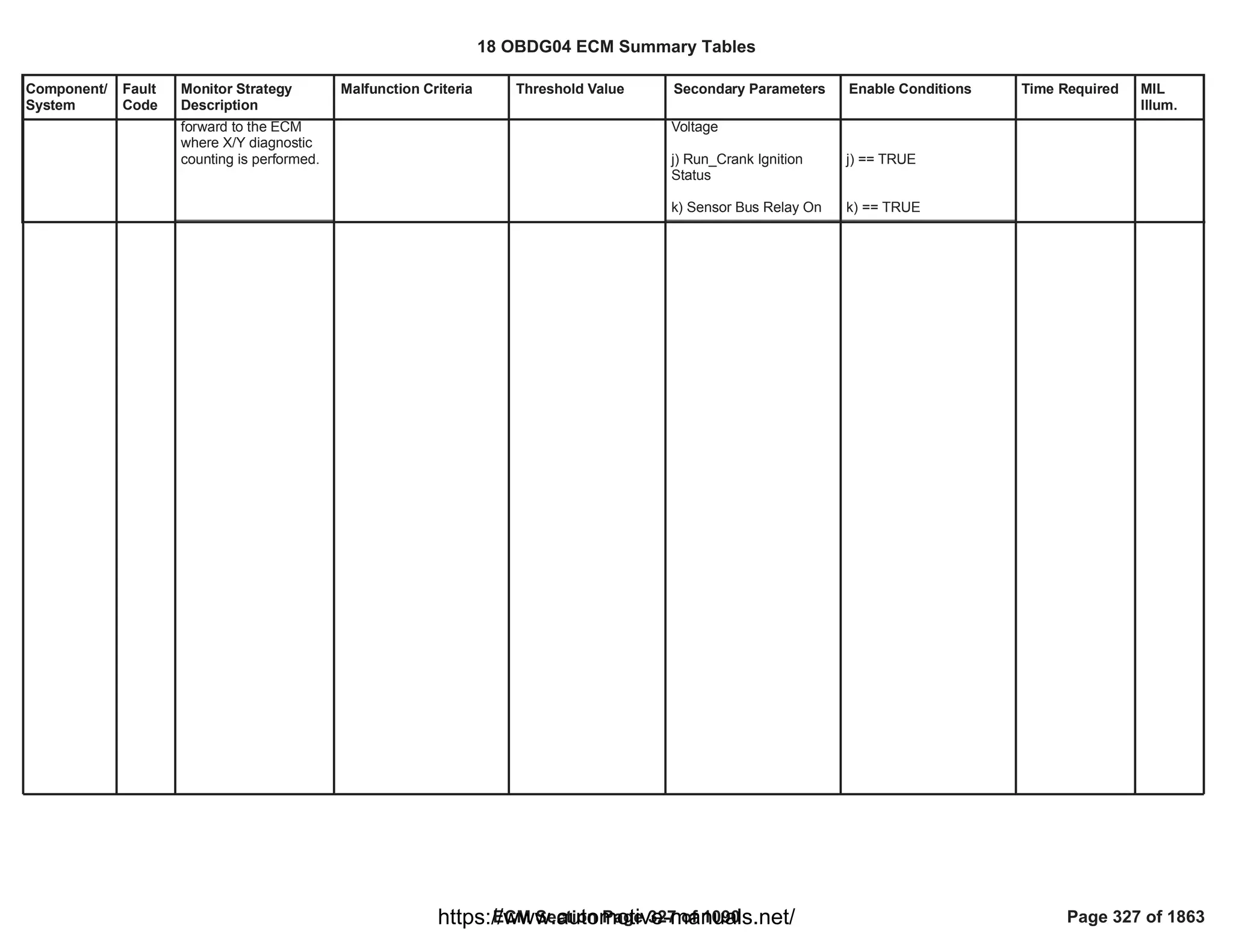
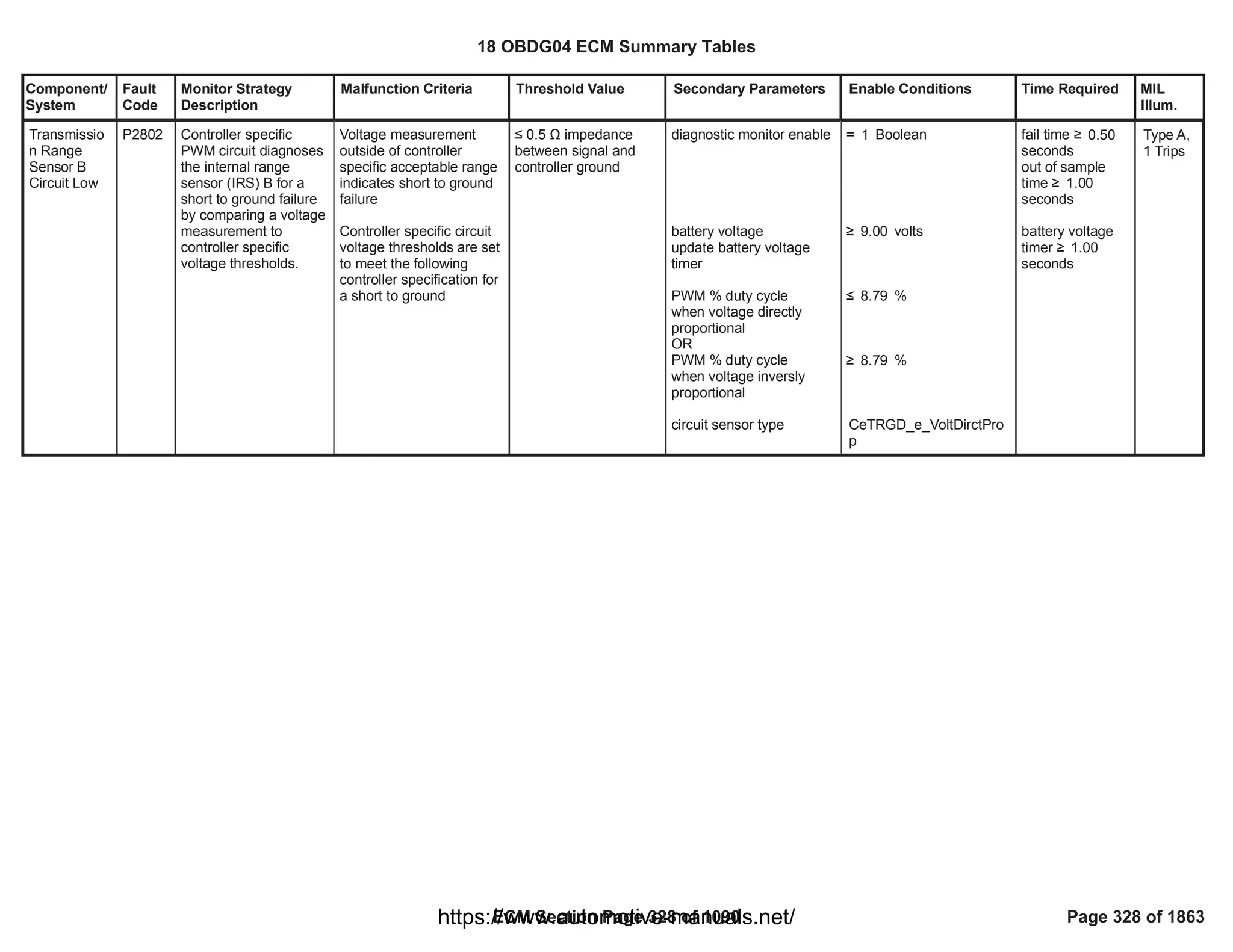
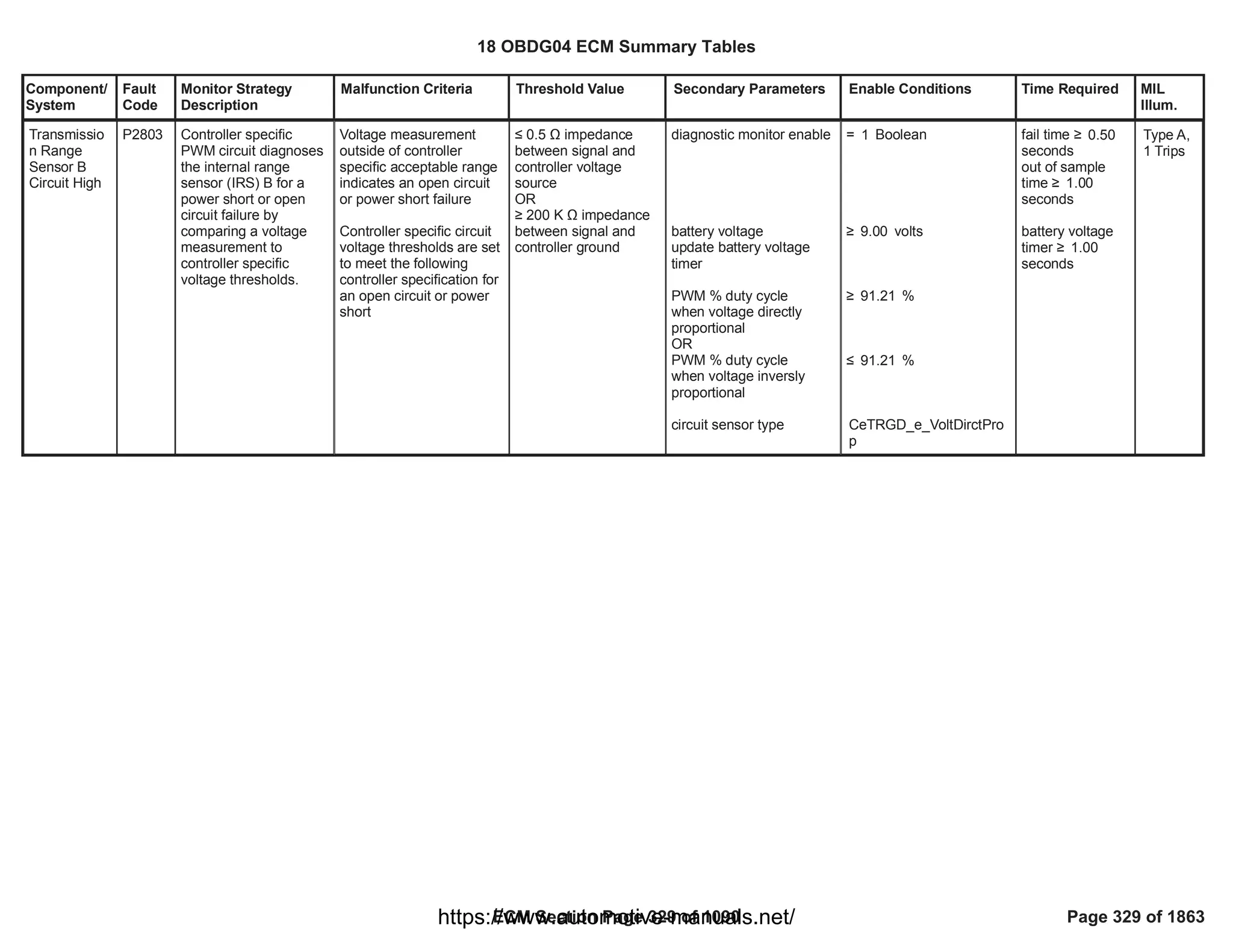
![Component/
System
Fault
Code
Monitor Strategy
Description
Malfunction Criteria Threshold Value Secondary Parameters Enable Conditions Time Required MIL
Illum.
Fuel Pump
Driver
Control
Module Lost
Communicati
on with ECM
[FPPM
applications
only]
U2616 To detect lost serial
data communication
from the power driver
controller to the ECM
Timer - Fuel System
Control message not
received
(FPPM Received Data
Communication Status)
t > 10 s
( Fu Pmp Pwr Mod
smart device reports
Faulted, Not Faulted or
Indeterminate)
a) Chassis Fuel Pres Sys
Type configuration
selection
b) Diagnostic Enabled
c) Diagnostic System
Disabled condition
d) FPPM Control Alive
Rolling Count Faulted
e) FPPM serial data
received [$0CE]
f) Run_Crank Input
Circuit Voltage
g) Run_Crank Ignition
Switch Position status
h) Sensor Bus Relay On
a) == FCBR ECM FPPM
Sys
b) == TRUE
c) <> True
d) <> True
e) == TRUE
f) > volts
7.00
g) == TRUE
h) == TRUE
failures /
64.00
samples
80.00
1 sample / 12.5
millisec
Type B,
2 Trips
18 OBDG04 ECM Summary Tables
ECM Section Page 330 of 1090 Page 330 of 1863
https://www.automotive-manuals.net/](https://image.slidesharecdn.com/gmcenginefaultcodesdtc1-230327071418-56d3c5bb/75/18-OBDG04-ECM-Summary-Tables-330-2048.jpg)
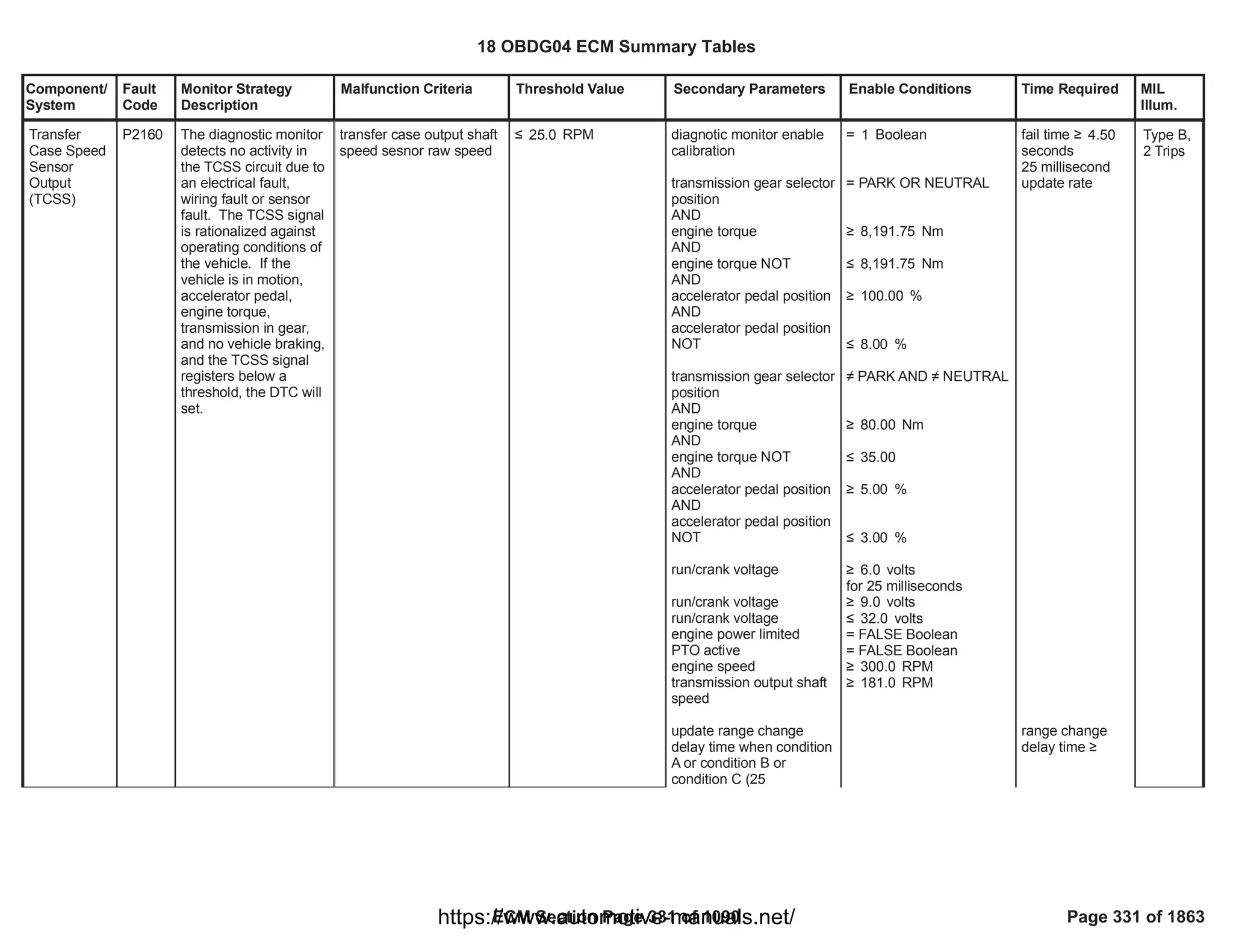
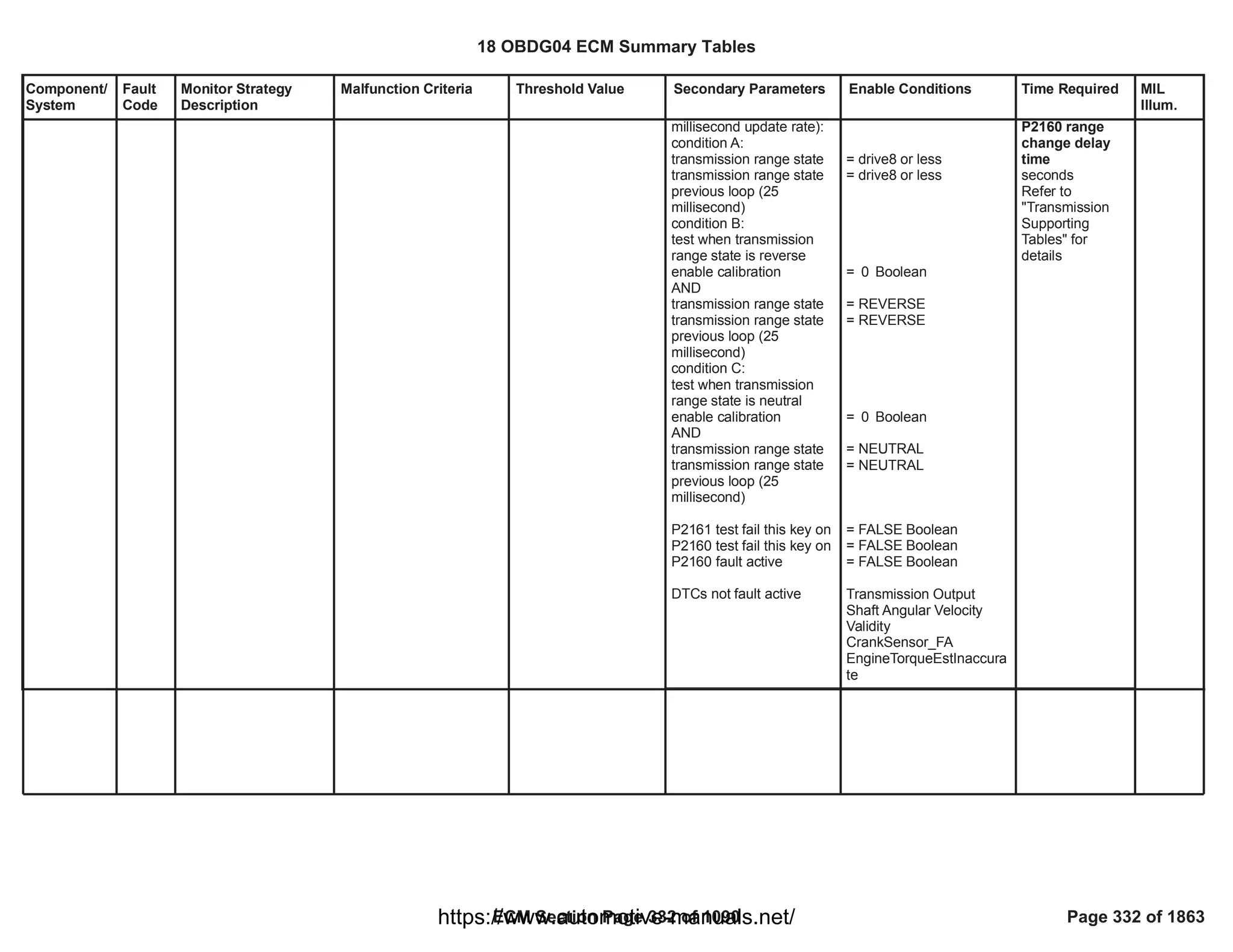
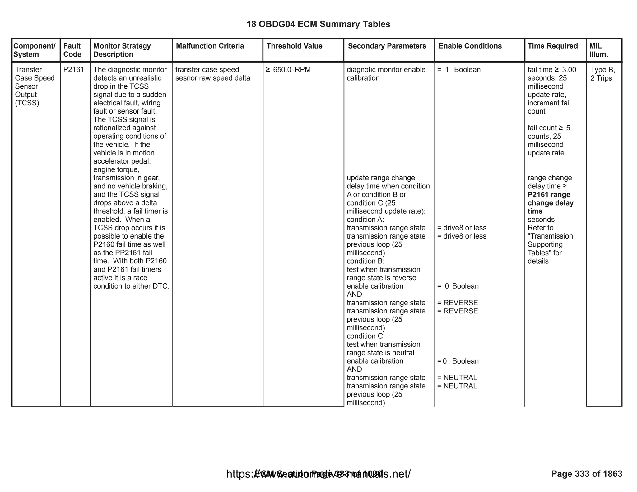
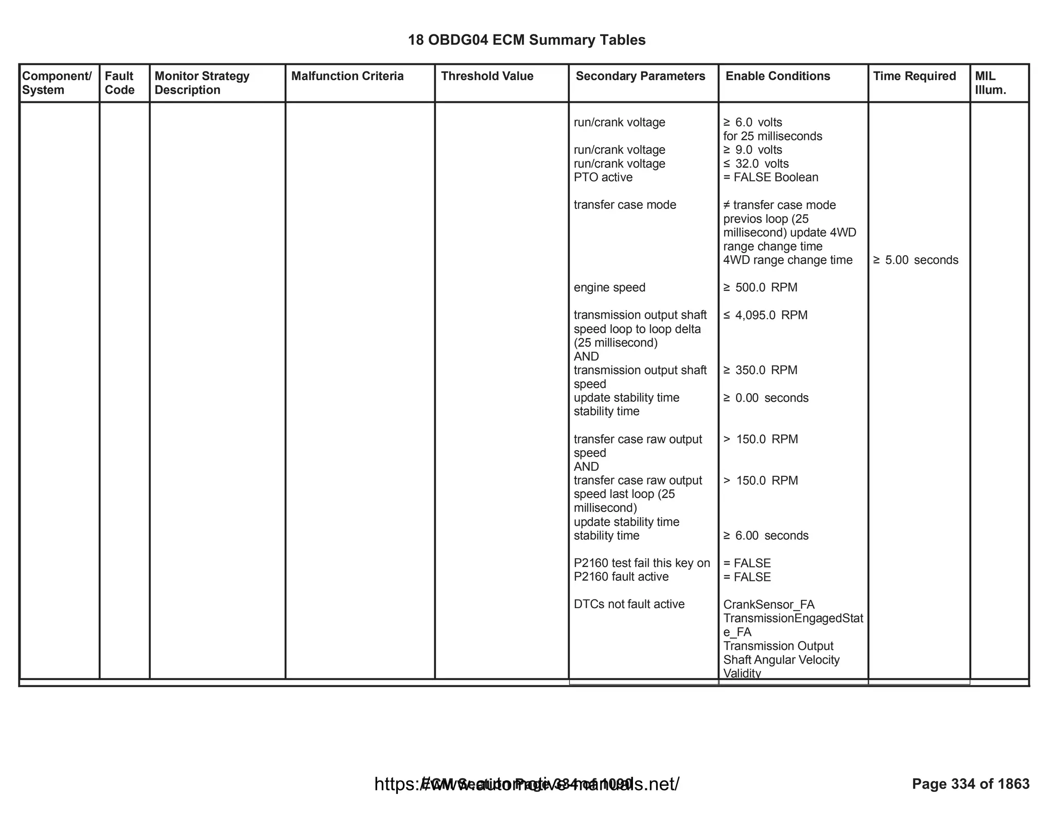
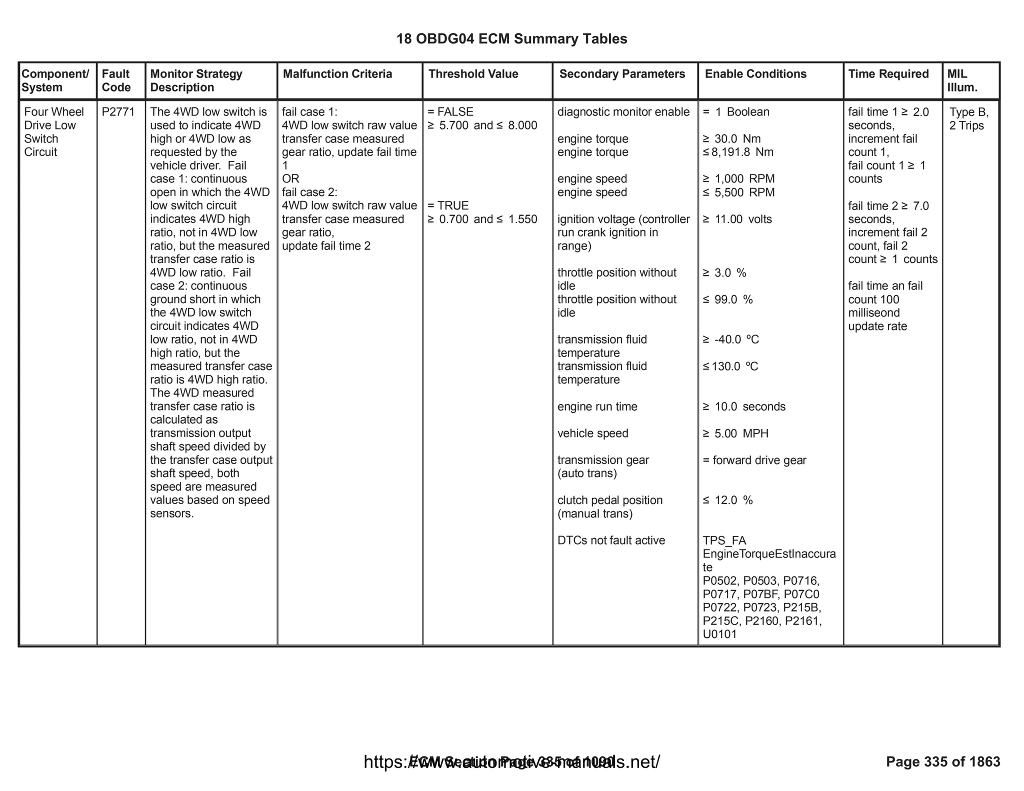
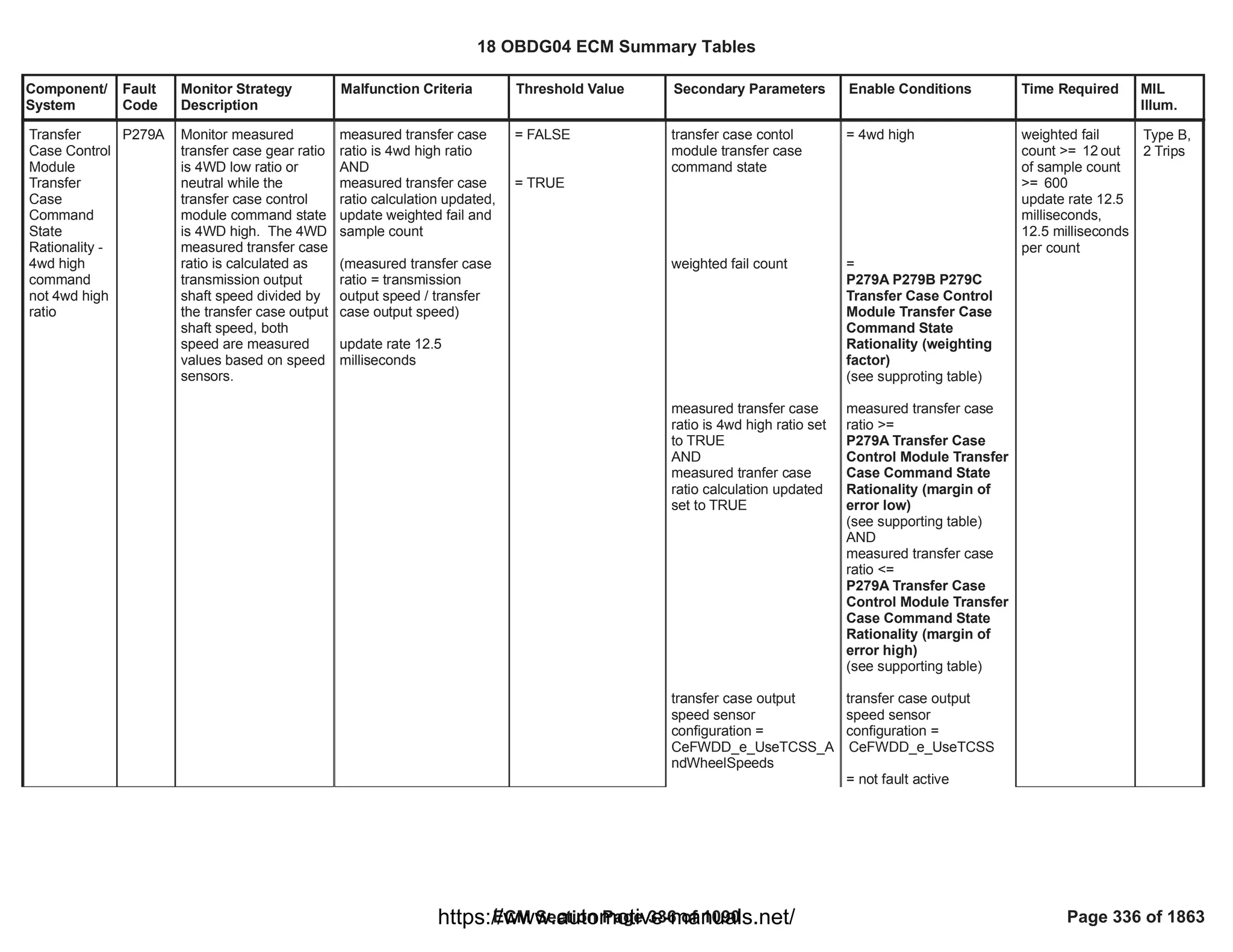
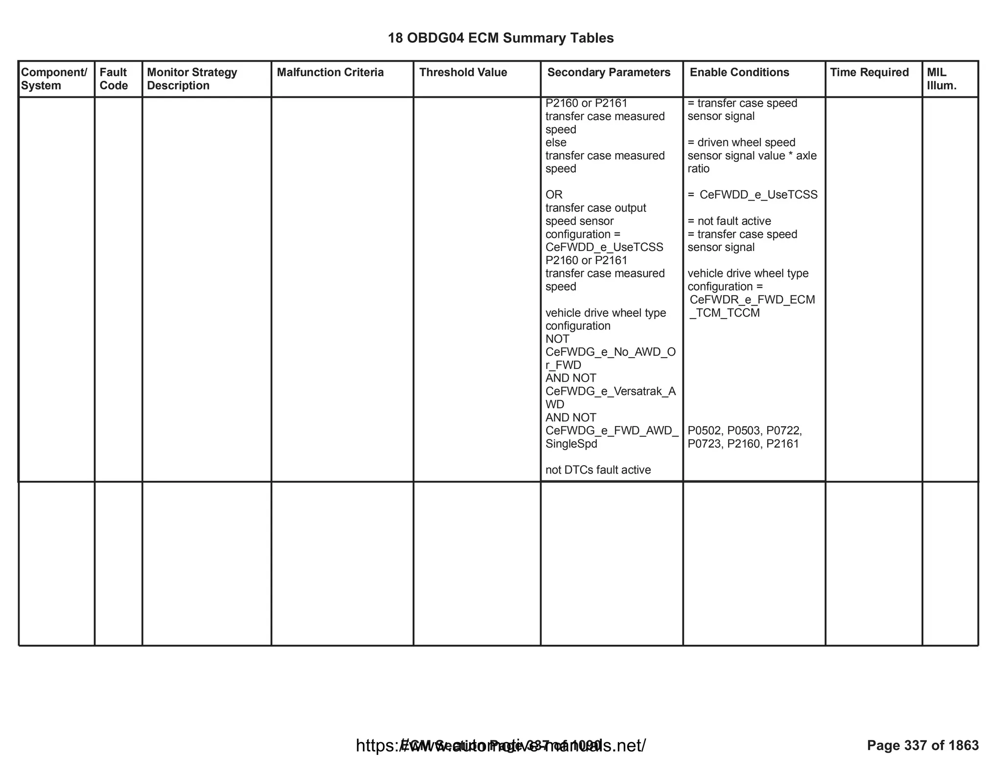
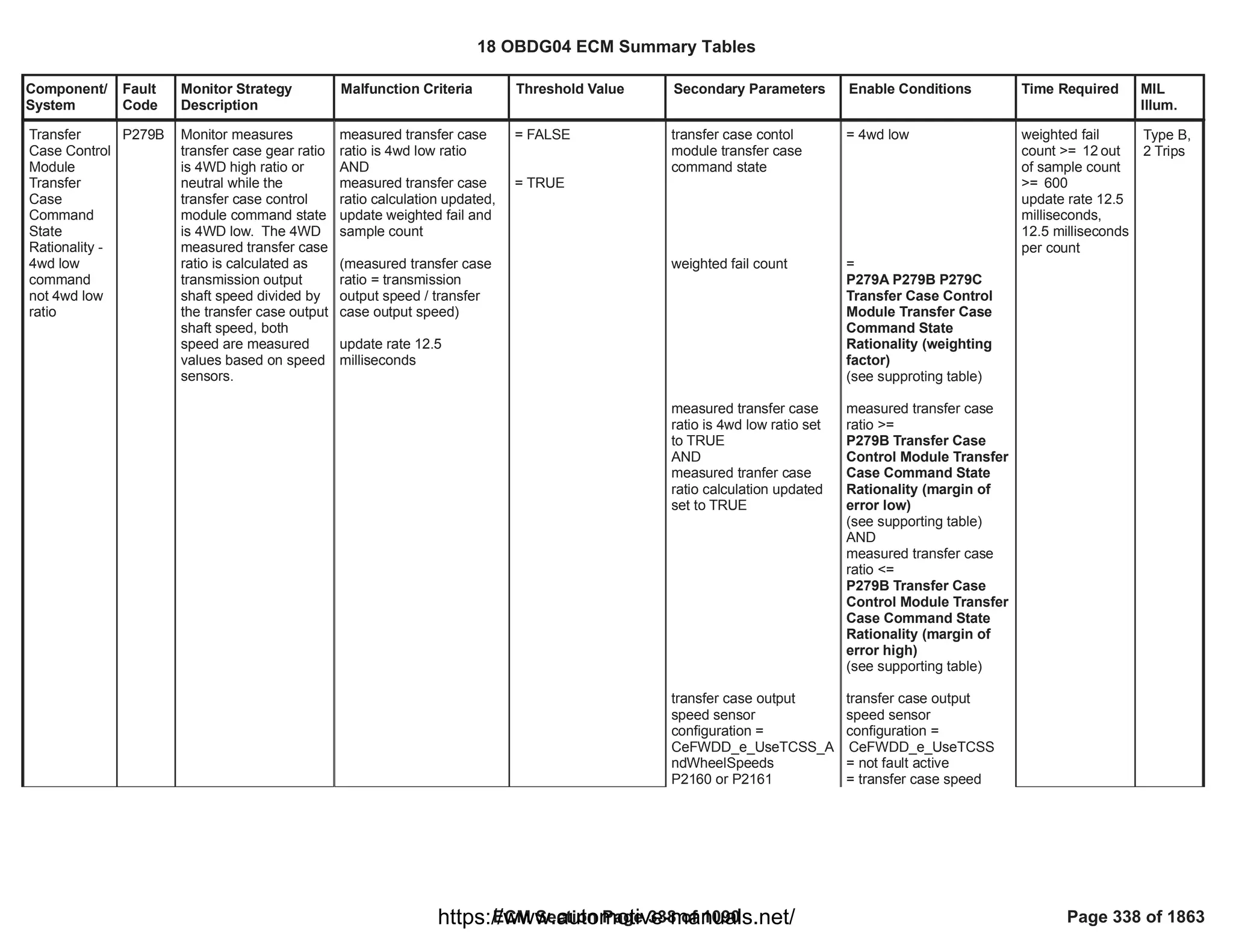
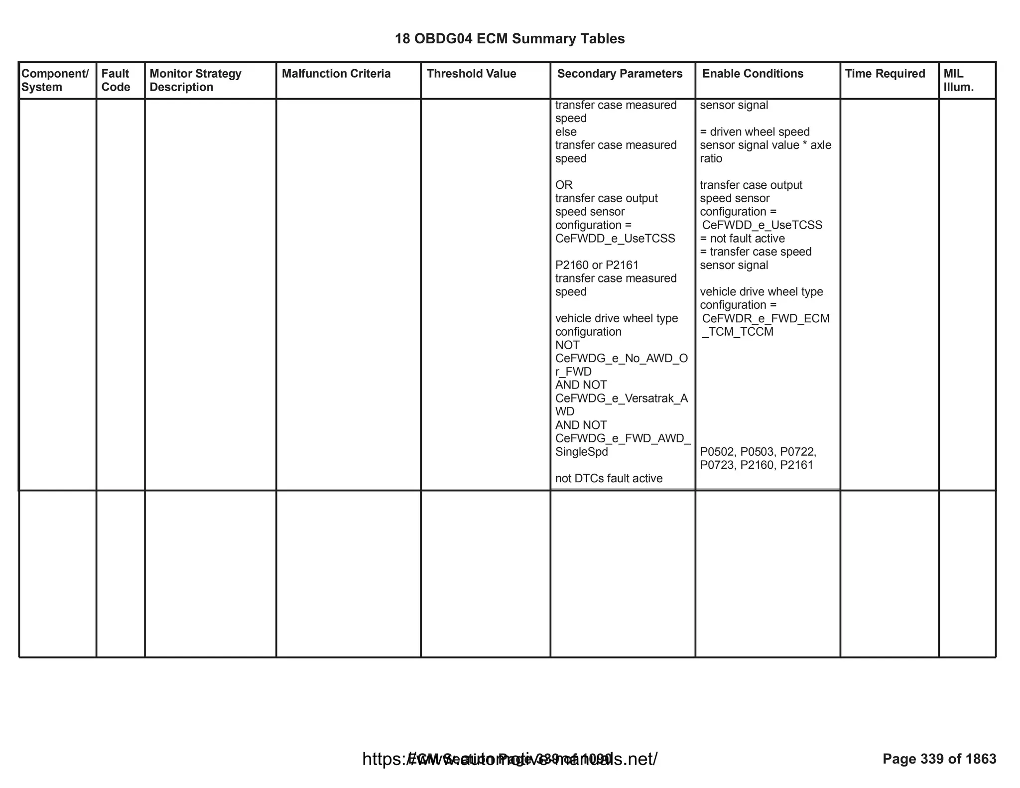
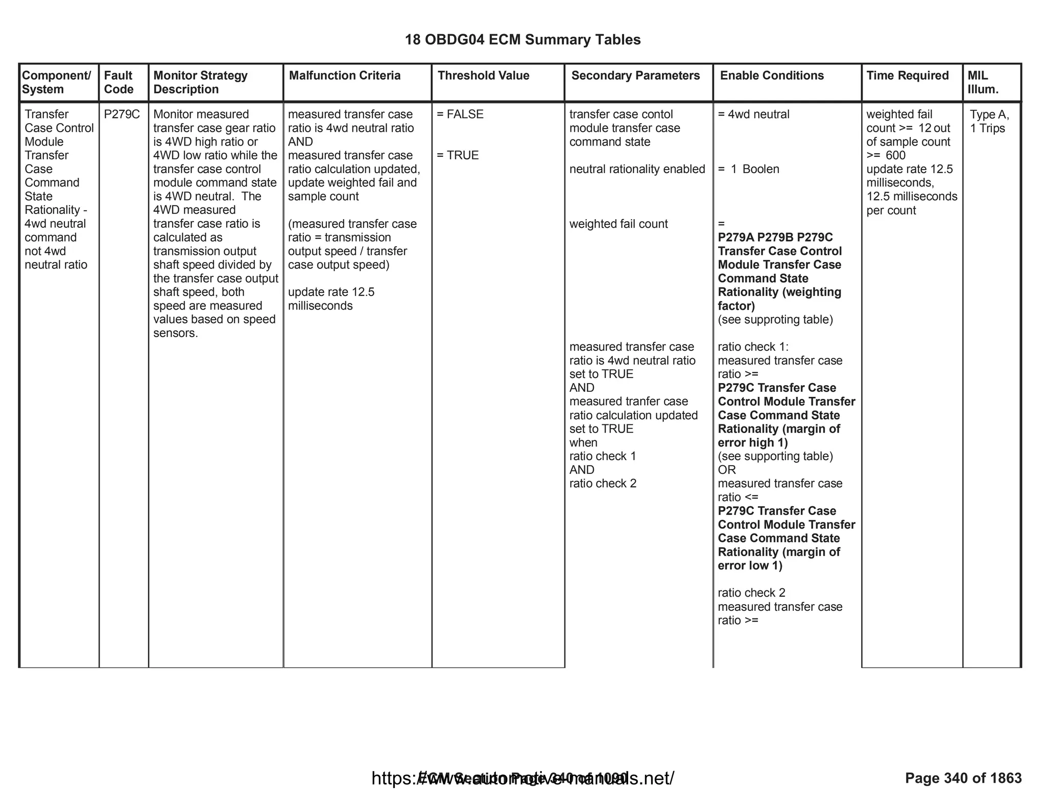
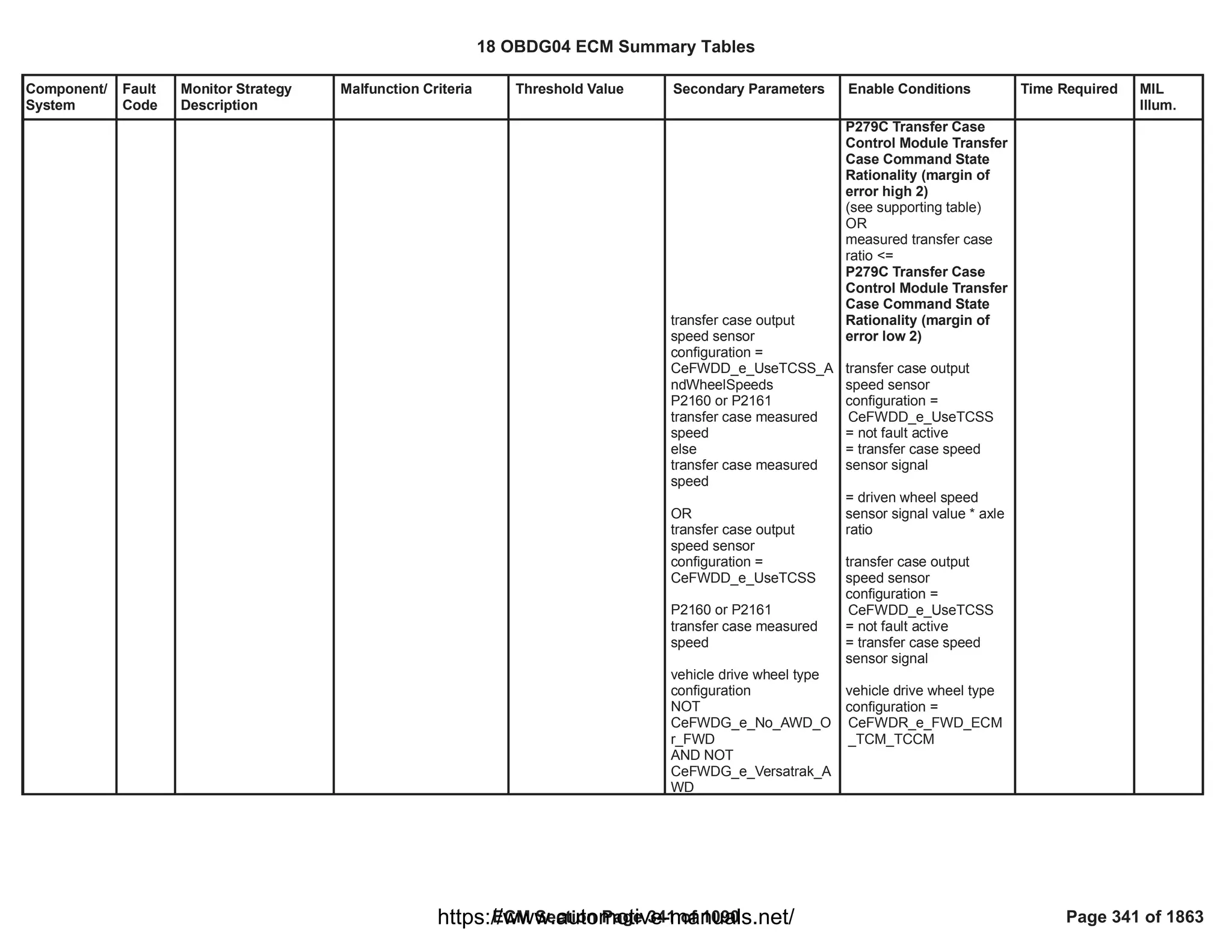
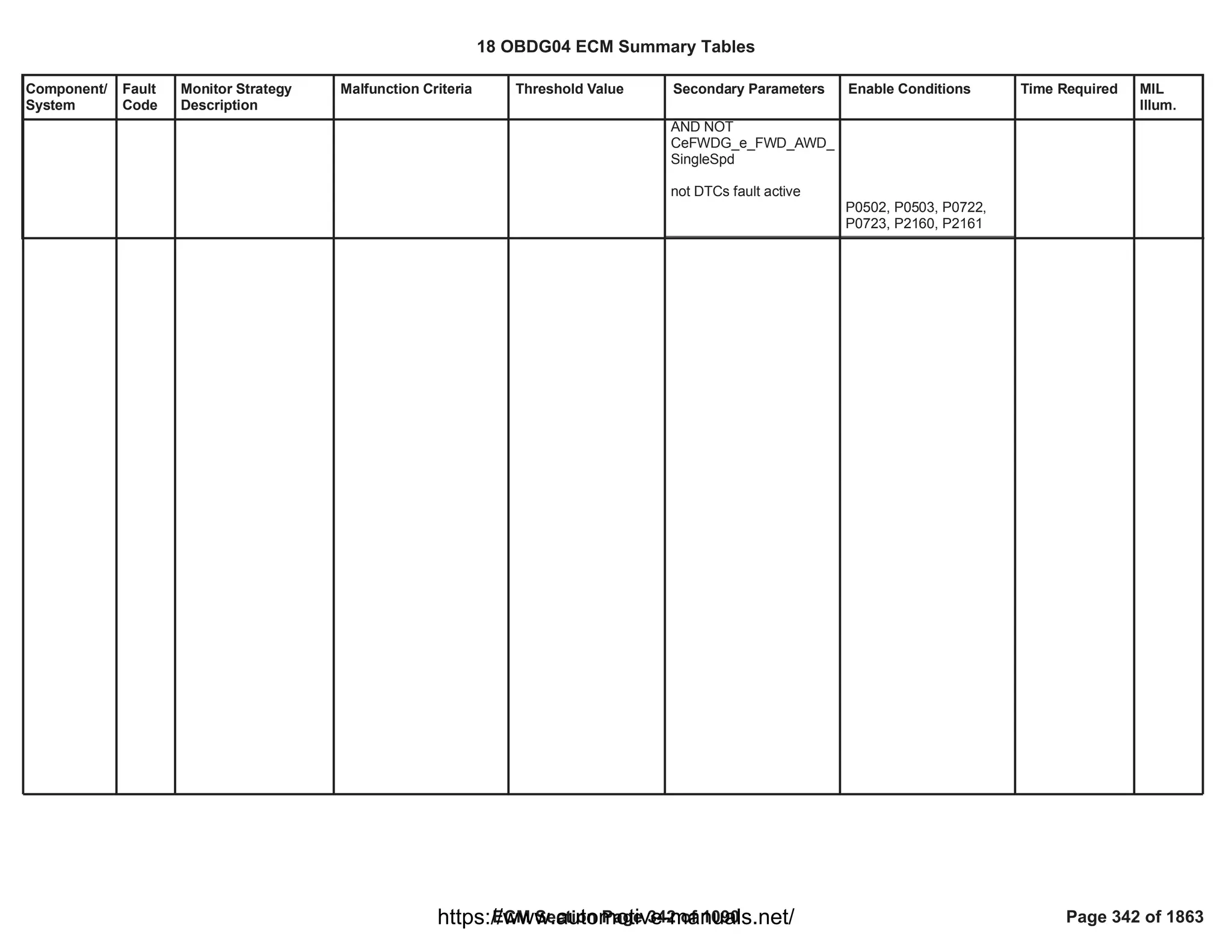
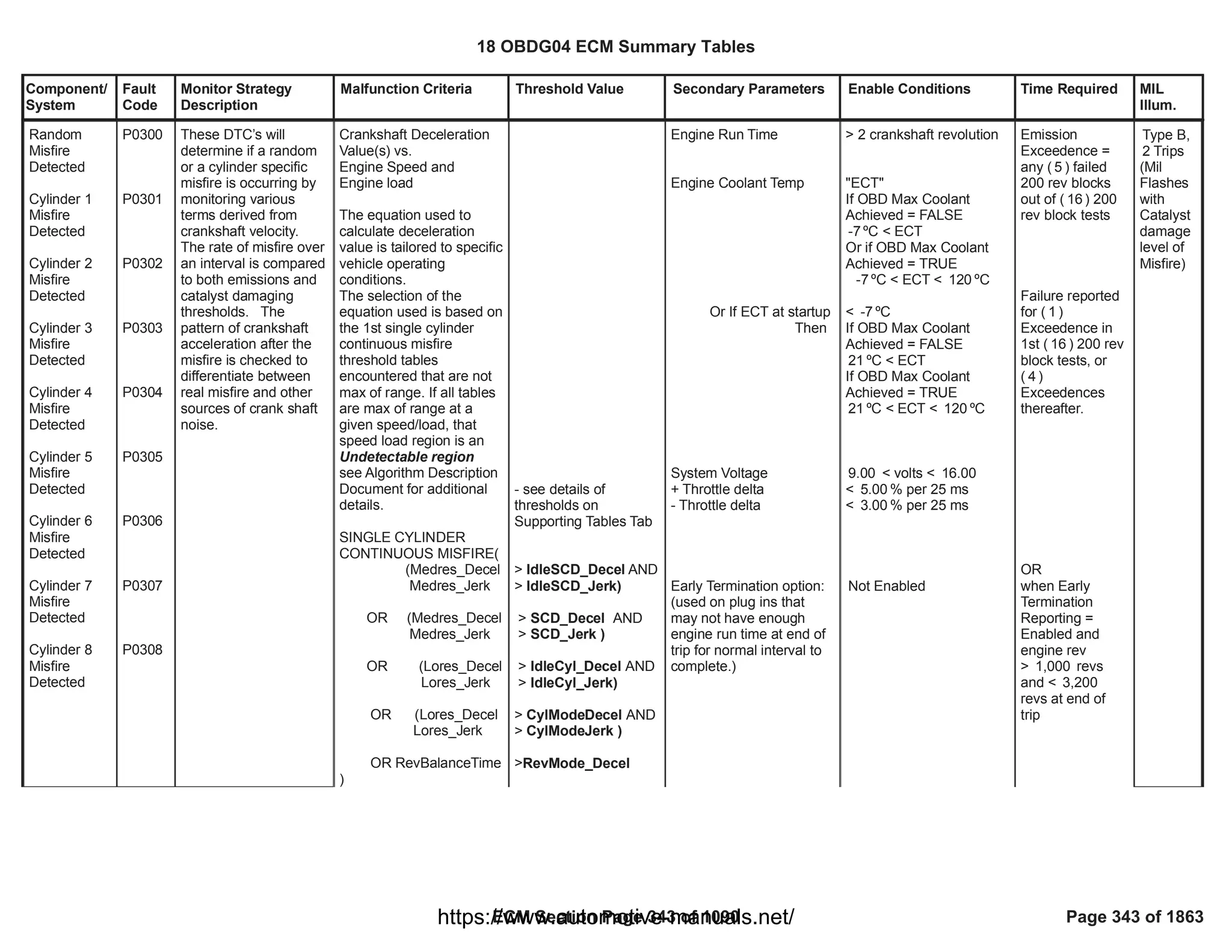
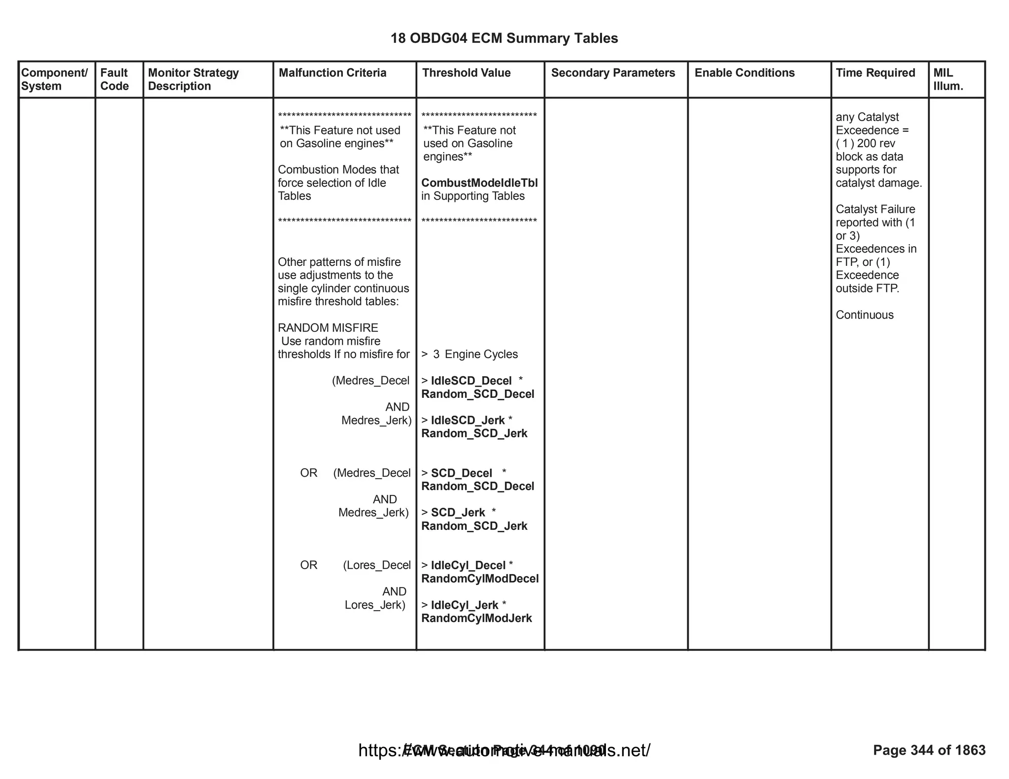
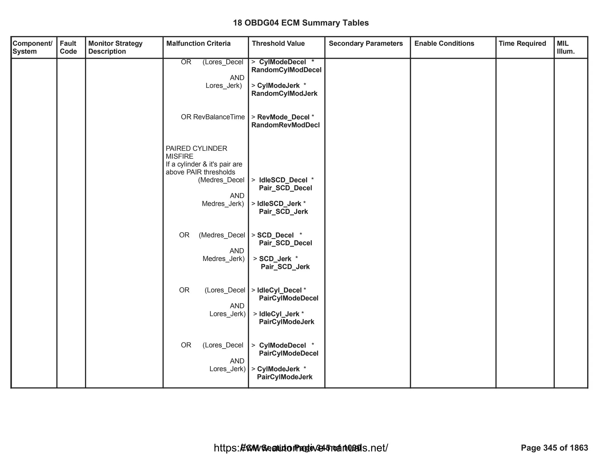
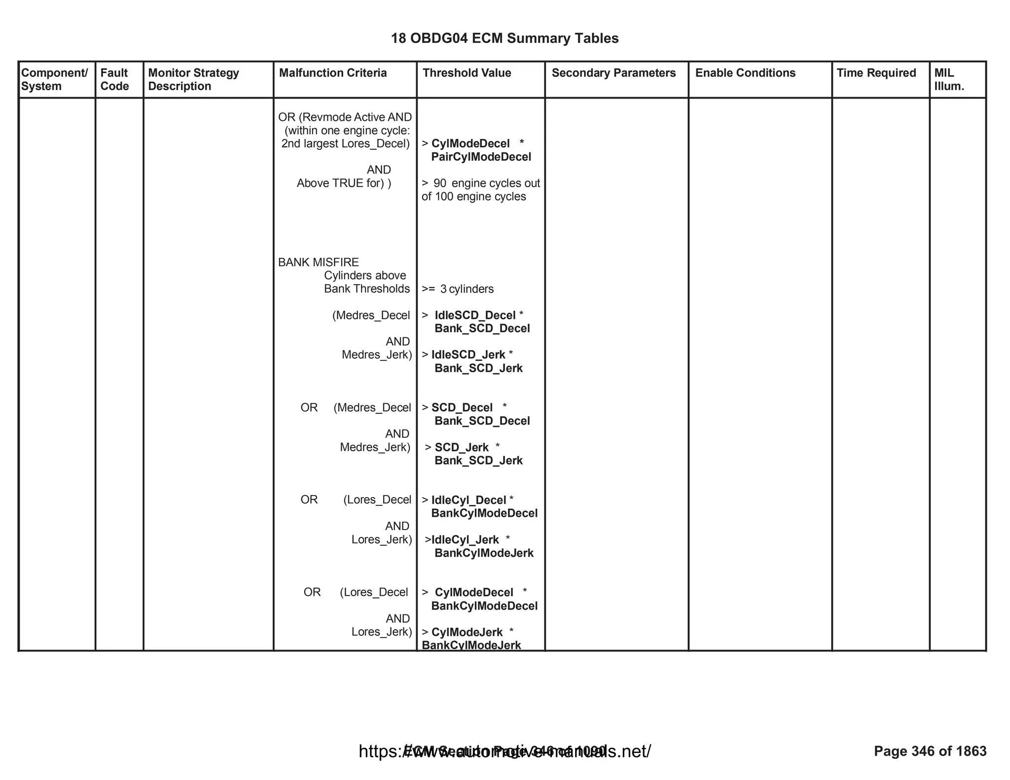

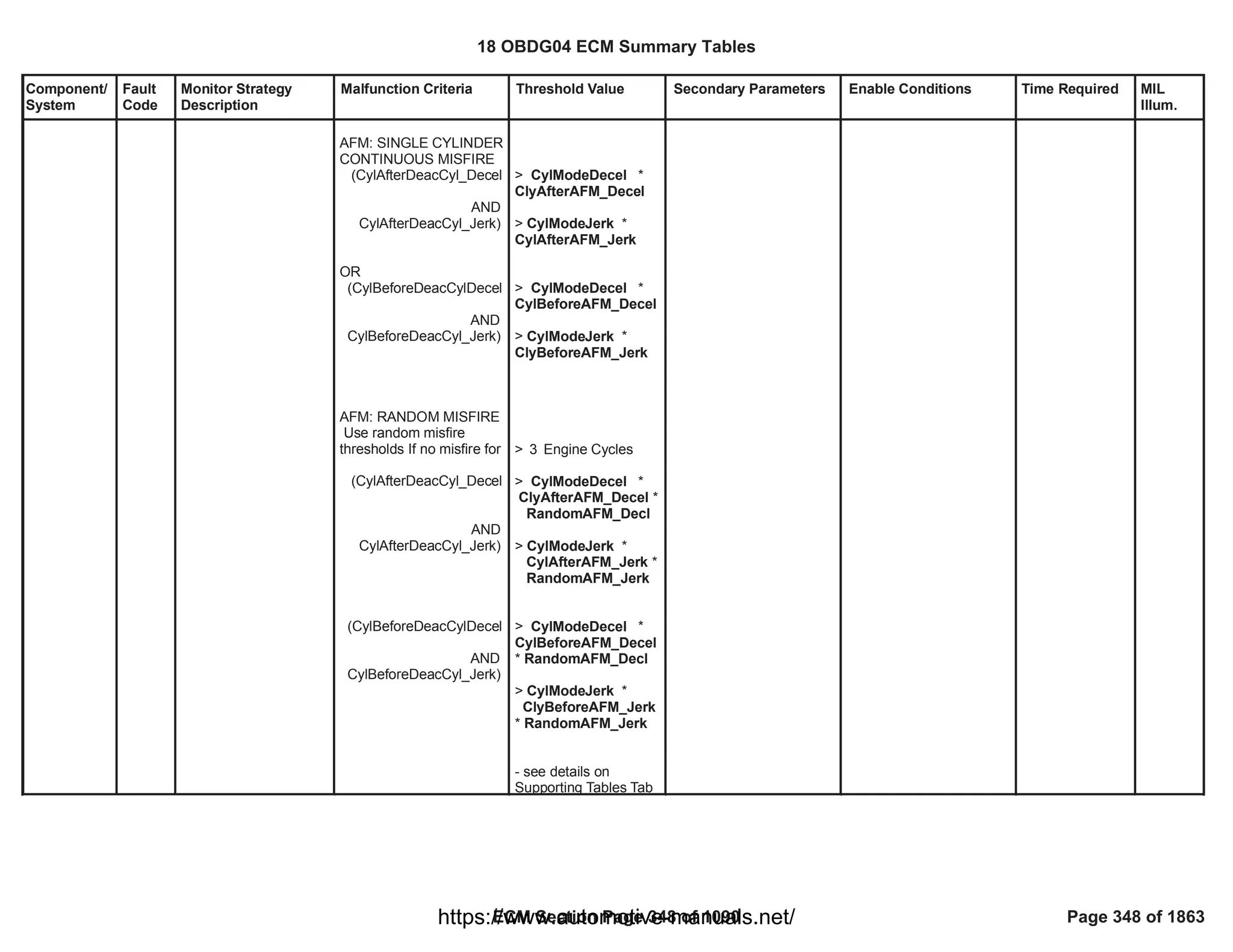
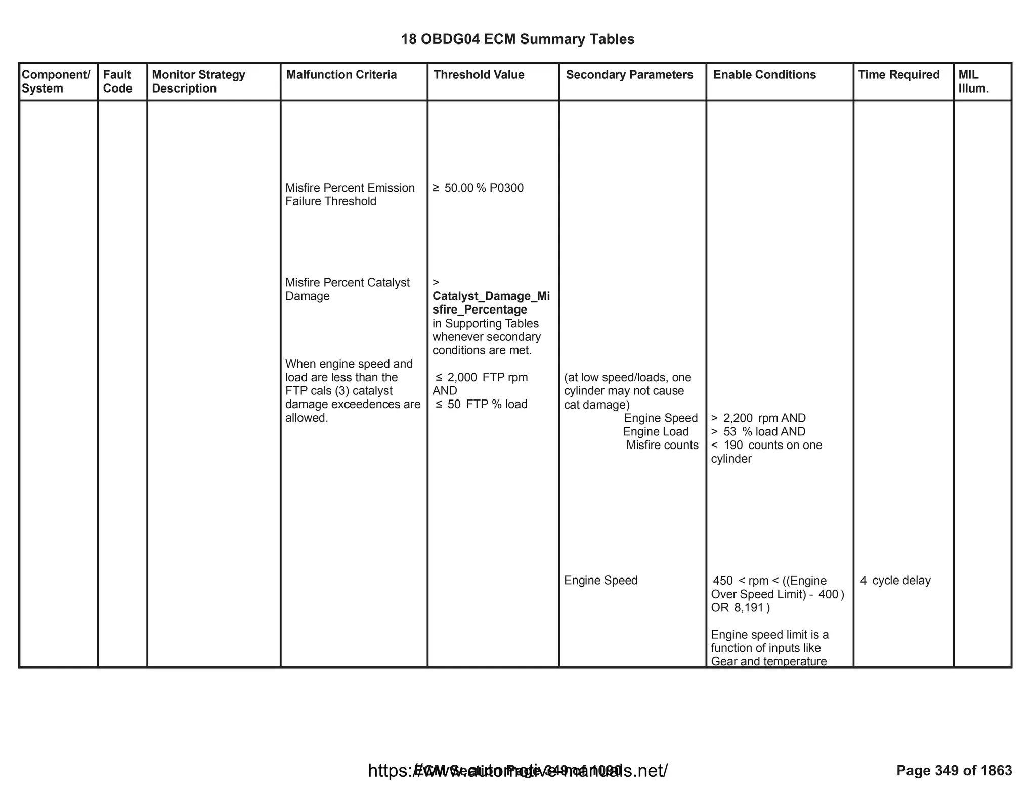
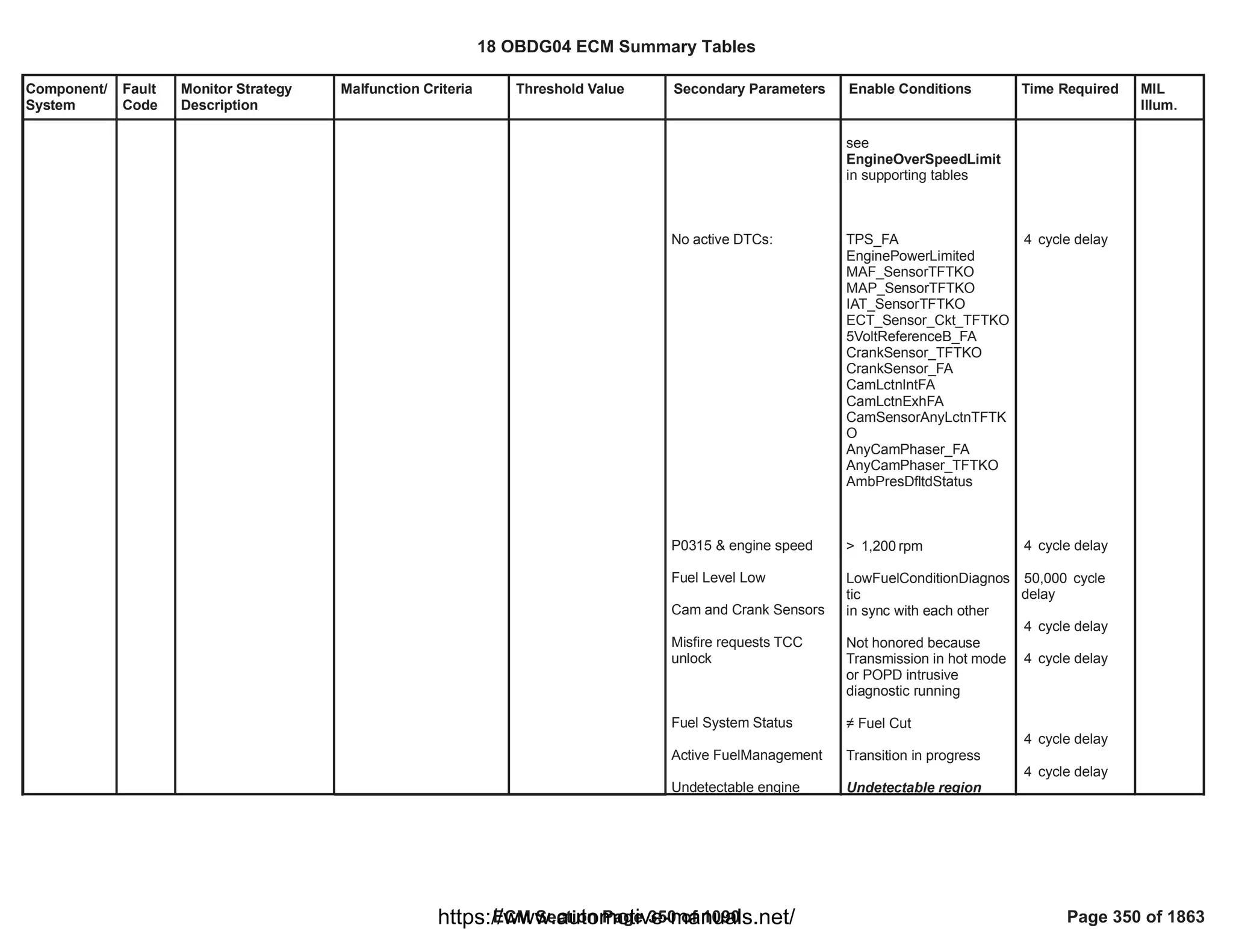
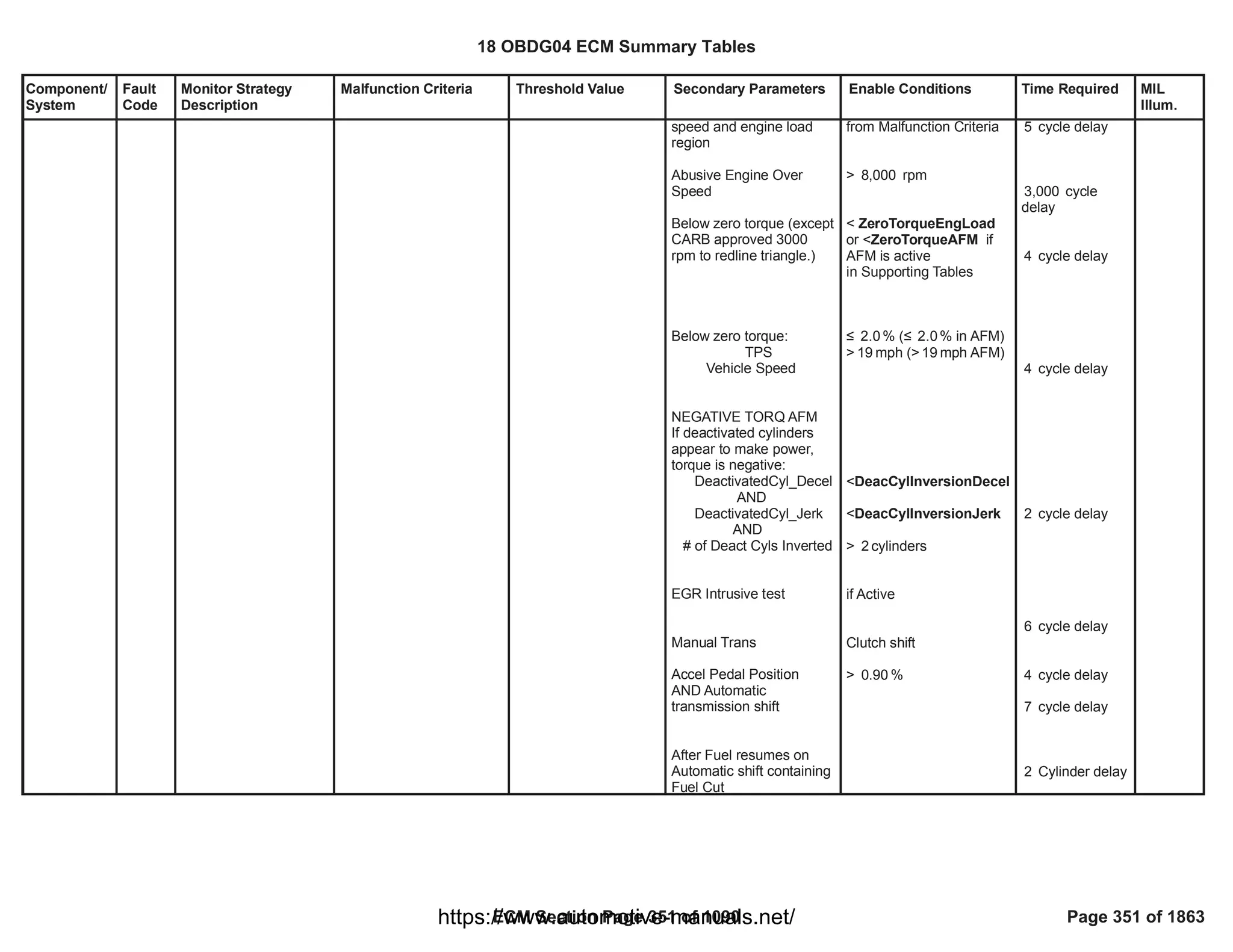
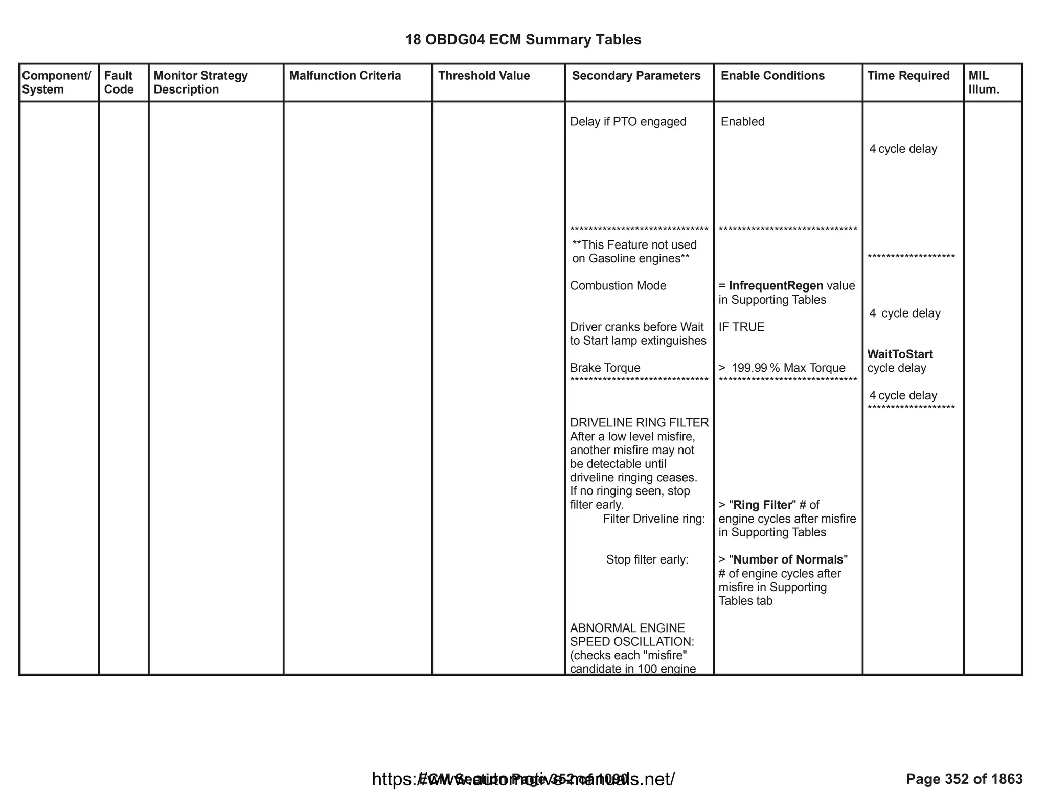
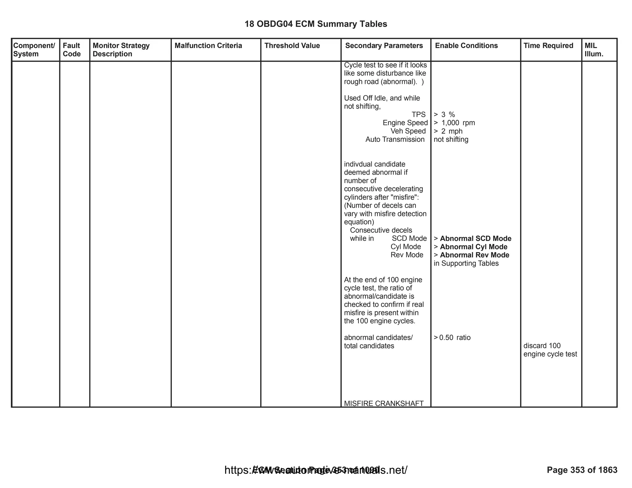
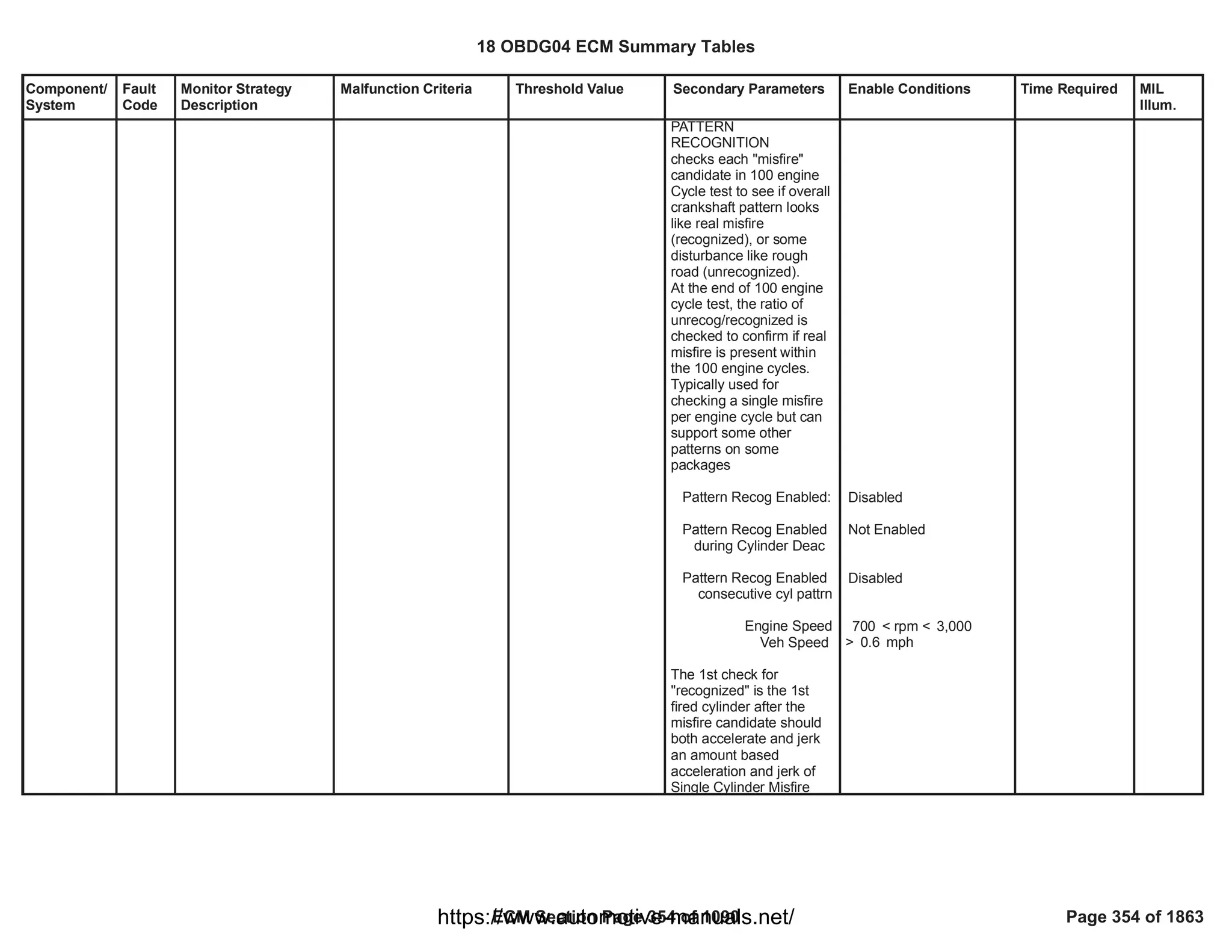
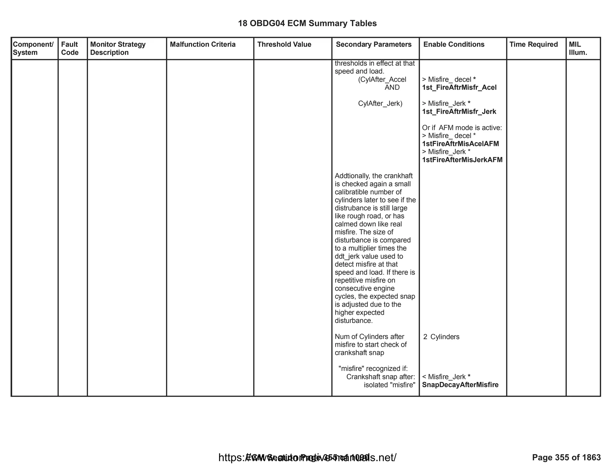
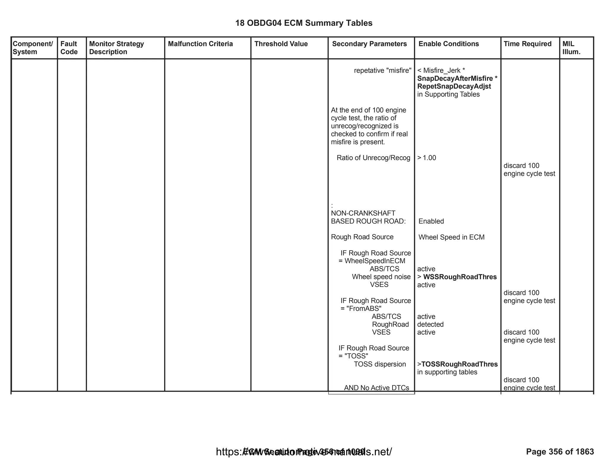
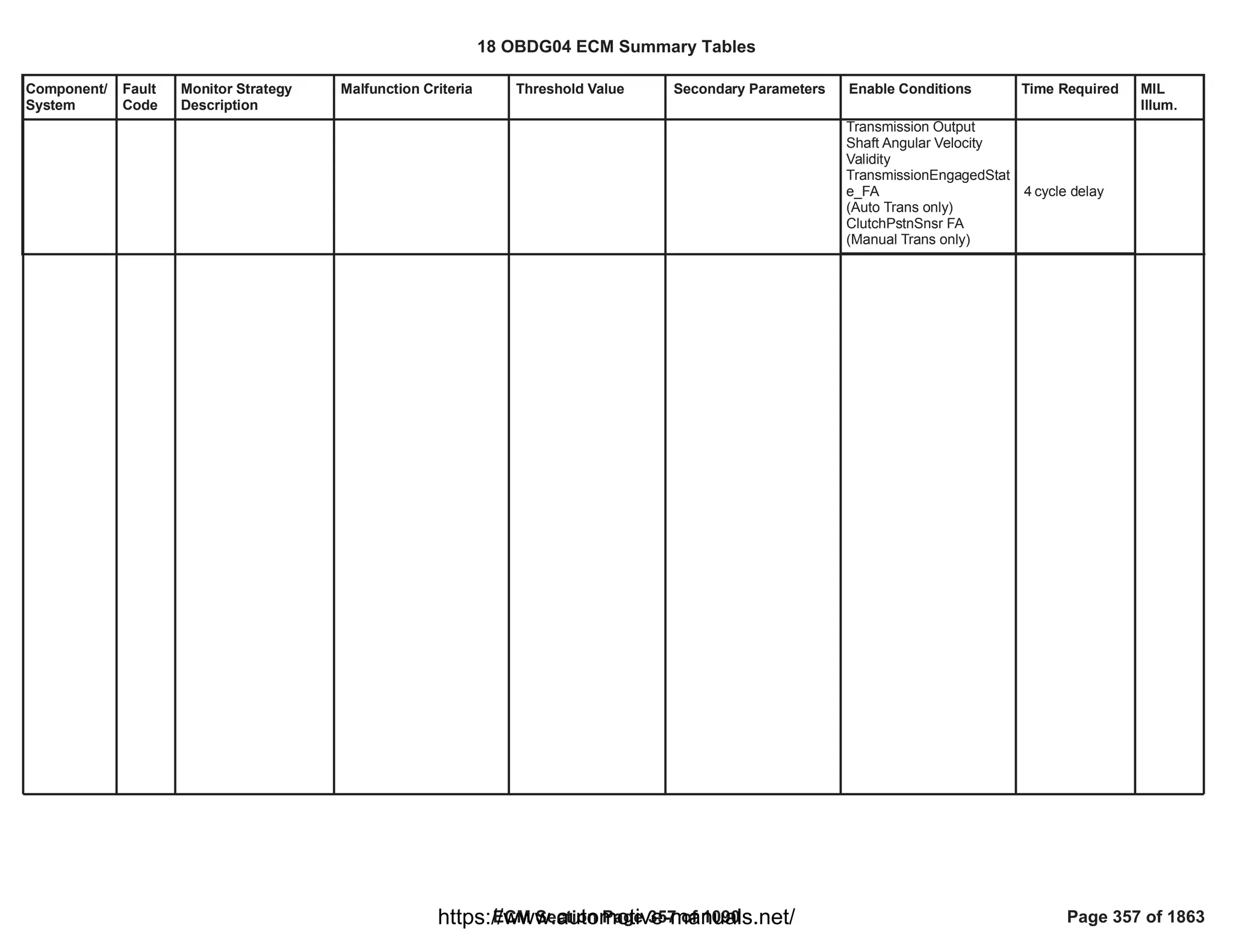
![Component/
System
Fault
Code
Monitor Strategy
Description
Malfunction Criteria Threshold Value Secondary Parameters Enable Conditions Time Required MIL
Illum.
Warm Up
Catalyst
Efficiency
Below
Threshold
Bank 1
P0421 The Catalyst (CC DOC)
monitor only runs
during DPF
regeneration and
compares the CC DOC
released oxidation heat
and the post-injected
fuel quantity both
evaluated inside a
determined portion of
the DPF regeneration
itself. This comparison
(ratio) produces an
Aging Index that shall
be greater than the
efficiency threshold, in
case of fresh (efficient)
Catalyst. If, instead, the
so calculated Aging
Index is below the
efficiency threshold, the
diagnosis reports fail
because the Catalyst is
too much damaged to
play well its role
(conversion inefficiency
detected) and shall be
replaced.
It is needed that post-
injection is enabled
during CC DOC
monitor in order to
produce enough
exothermic heat across
the Catalyst to evaluate
the component
conversion efficiency in
a reliable way.
EWMA Filtering
functionality (including
Catalyst Aging Index <
Threshold
If
- Catalyst EWMA filter
enabling calibration =
TRUE
AND
- Catalyst conversion
inefficiency previously
detected (Catalyst Fault
Active = TRUE)
Then:
Catalyst Aging Index <
Repass Threshold
Aging Index <
CatCrtdEffThrsh
[Curve]
If
EWMA Enbl Cal =
[Boolean]
0.00
AND
Catalyst FA =
CAT_CatSysEffLoB1_F
A
Then:
Aging Index <
CatCrtdEffRepEWMA
[Curve]
- Catalyst monitor in DPF
regeneration enabled by
calibrations
AND
No active DTCs:
- Catalyst up temperature
sensor not in fault (Fault
Flag = FALSE)
AND
- Catalyst down
temperature sensor not in
fault (Fault Flag =
FALSE);
Temperature Learning
concluded:
- Number of elapsed
samples (task time = 100
[ms]) equal to calibration;
Catalyst monitor status
is DISABLED if:
- DPF regeneration
disabled
OR
- Injection system in fault
(Fault Flag = TRUE)
OR
- Ambient temperature
RegenMonitorEnabled =
[Boolean]
0.00
AND
DPF_RegenMonitorSelect
ed = NOT( 1.00
[Boolean])
AND
ReportingEnabled= 1.00
[Boolean]
AND
Cat Up Temp Snsr Flt =
NOT ( )
EGT_SnsrCatUpFlt
AND
Cat Dwn Temp Snsr Flt =
NOT
( );
EGT_SnsrCatDwnFlt
Samples nr. = 10.00
[Counter];
Catalyst monitor status
is DISABLED if:
=
DPF_DPF_St
SootLoading
[Enumerative]
OR
Injection System Flt =
FUL_GenericInjSysFlt
OR
Amb Temp FA =
CAT_OutsideTempFA
Task Time = 100
[ms]
If
- Catalyst EWMA
filter enabling
cailibration =
FALSE (EWMA
Enbl Cal = 0.00
[Boolean])
Then:
2 trips (with
malfunction) to
set DTC (Type
B)
If
- Catalyst EWMA
filter enabling
cailibration =
TRUE (EWMA
Enbl Cal = 0.00
[Boolean])
AND
- EWMA status =
EWMA Standard
Then:
1 trip (with
malfunction) to
set DTC (Type A)
If
- Catalyst EWMA
filter enabling
cailibration =
TRUE (EWMA
Enbl Cal = 0.00
[Boolean])
Type B,
2 Trips
18 OBDG04 ECM Summary Tables
ECM Section Page 358 of 1090 Page 358 of 1863
https://www.automotive-manuals.net/](https://image.slidesharecdn.com/gmcenginefaultcodesdtc1-230327071418-56d3c5bb/75/18-OBDG04-ECM-Summary-Tables-358-2048.jpg)
![Component/
System
Fault
Code
Monitor Strategy
Description
Malfunction Criteria Threshold Value Secondary Parameters Enable Conditions Time Required MIL
Illum.
Fast Initial Response
(FIR), Rapid Response
(RR) and EWMA
Standard) is supported
by the Catalyst (CC
DOC) monitor.
information in fault (Fault
Active = TRUE)
OR
- Catalyst up exhaust flow
estimation in fault (Fault
Flag = TRUE)
OR
- Ambient conditions not
always satisfied while
engine running:
Ambient pressure lower
than calibration
OR
Ambient temperature
lower than calibration
OR
- Catalyst monitor already
performed successfully in
current driving cycle
(Catalyst monitor shall run
only once per driving
cycle)
OR
HC unloading enabled;
Catalyst monitor status
can move from
DISABLED to
TRIGGERED if:
- DPF regeneration
enabled
AND
- Injection system not in
fault (Fault Flag = FALSE)
AND
- Ambient temperature
information not in fault
OR
Cat Up Exh Flow Flt =
EXF_TotExhCatUpFlt
OR
- Ambient conditions not
always satisfied while
engine running:
Amb Press < [KPa]
0.00
OR
Amb Temp < [K]
0.00
OR
Catalyst monitor already
performed successfully in
current driving cycle
(Catalyst monitor shall run
only once per driving
cycle) [Boolean]
OR
=
HCI_DeHC_ExhInjDsbl
TRUE [Boolean];
Catalyst monitor status
can move from
DISABLED to
TRIGGERED if:
DPF_DPF_St
SootLoading
[Enumerative]
AND
Injection System Flt =
NOT
( )
FUL_GenericInjSysFlt
AND
Amb Temp FA = NOT
( )
CAT_OutsideTempFA
AND
- EWMA status =
Fast Initial
Response (FIR)
Then:
- 1 trip (with
malfunction) to
set DTC (Type A)
and return to
EWMA status =
EWMA Standard
- [Counter]
0.00
elapsed trips
(with no
mulfunction) to
report pass and
return to EWMA
status = EWMA
Standard
If
- Catalyst EWMA
filter enabling
cailibration =
TRUE (EWMA
Enbl Cal = 0.00
[Boolean])
AND
- EWMA status =
Rapid Response
(RR)
Then:
- 1 trip (with
malfunction) to
set DTC (Type A)
and return to
EWMA status =
EWMA Standard
- 1 trip (with no
mulfunction) to
report pass
- [Counter]
0.00
18 OBDG04 ECM Summary Tables
ECM Section Page 359 of 1090 Page 359 of 1863
https://www.automotive-manuals.net/](https://image.slidesharecdn.com/gmcenginefaultcodesdtc1-230327071418-56d3c5bb/75/18-OBDG04-ECM-Summary-Tables-359-2048.jpg)
![Component/
System
Fault
Code
Monitor Strategy
Description
Malfunction Criteria Threshold Value Secondary Parameters Enable Conditions Time Required MIL
Illum.
(Fault Active = FALSE)
AND
- Catalyst up exhaust flow
estimation not in fault
(Fault Flag = FALSE)
AND
- Ambient conditions
always satisfied while
engine running:
Ambient pressure higher
than calibration
AND
Ambient temperature
higher than calibration
AND
- Catalyst monitor not yet
performed successfully in
current driving cycle
(Catalyst monitor shall run
only once per driving
cycle)
AND
- If
DPF regeneration has
been interrupted in
previous driving cycle or
in current driving cycle
Then:
Engine coolant
temperature lower than
calibration
AND
- Catalyst up exhaust
temperature (by sensor)
lower than calibration
AND
HC unloading disabled;
Catalyst monitor status
can move from
TRIGGERED to
AND
Cat Up Exh Flow Flt =
NOT
( )
EXF_TotExhCatUpFlt
AND
Ambient conditions
always satisfied while
engine running:
Amb Press > [KPa]
0.00
AND
Amb Temp > [K]
0.00
AND
Catalyst monitor not yet
performed successfully in
current driving cycle
(Catalyst monitor shall run
only once per driving
cycle) [Boolean]
AND
If
Interrupted DPF
regeneration counter > 0
[Counter]
Then:
Eng Cool Temp < [°
0.39
C]
AND
Cat Up Temp Snsr < 0.00
[K];
AND
=
HCI_DeHC_ExhInjDsbl
FALSE [Boolean];
Catalyst monitor status
can move from
TRIGGERED to
elapsed trips
(with no
mulfunction) to
report pass and
return to EWMA
status = EWMA
Standard
18 OBDG04 ECM Summary Tables
ECM Section Page 360 of 1090 Page 360 of 1863
https://www.automotive-manuals.net/](https://image.slidesharecdn.com/gmcenginefaultcodesdtc1-230327071418-56d3c5bb/75/18-OBDG04-ECM-Summary-Tables-360-2048.jpg)
![Component/
System
Fault
Code
Monitor Strategy
Description
Malfunction Criteria Threshold Value Secondary Parameters Enable Conditions Time Required MIL
Illum.
ENABLED (oxidation
heat release integrator
and post injected fuel
integrator are both
enabled) if:
- DPF regeneration
enabled
AND
- Injection system not in
fault (Fault Flag = FALSE)
AND
- Ambient temperature
information not in fault
(Fault Active = FALSE)
AND
- Catalyst up exhaust flow
estimation not in fault
(Fault Flag = FALSE)
AND
- Ambient conditions
always satisfied while
engine running:
Ambient pressure higher
than calibration
AND
Ambient temperature
higher than calibration
AND
- Catalyst monitor not yet
performed successfully in
current driving cycle
(Catalyst monitor shall run
only once per driving
cycle)
AND
- Catalyst up exhaust
temperature (by sensor)
higher than calibration
AND
- Post injection enabled
ENABLED (oxidation
heat release integrator
and post injected fuel
integrator are both
enabled) if:
DPF_DPF_St
SootLoading
[Enumerative]
AND
Injection System Flt =
NOT
( )
FUL_GenericInjSysFlt
AND
Amb Temp FA = NOT
( )
CAT_OutsideTempFA
AND
Cat Up Exh Flow Flt =
NOT
( )
EXF_TotExhCatUpFlt
AND
- Ambient conditions
always satisfied while
engine running:
Amb Press > [KPa]
0.00
AND
Amb Temp > [K]
0.00
AND
Catalyst monitor not yet
performed successfully in
current driving cycle
(Catalyst monitor shall run
only once per driving
cycle) [Boolean]
AND
Cat Up Temp Snsr > 0.00
[K]
AND
= TRUE
FUL_PostEnbl
18 OBDG04 ECM Summary Tables
ECM Section Page 361 of 1090 Page 361 of 1863
https://www.automotive-manuals.net/](https://image.slidesharecdn.com/gmcenginefaultcodesdtc1-230327071418-56d3c5bb/75/18-OBDG04-ECM-Summary-Tables-361-2048.jpg)
![Component/
System
Fault
Code
Monitor Strategy
Description
Malfunction Criteria Threshold Value Secondary Parameters Enable Conditions Time Required MIL
Illum.
AND
- Catalyst up exhaust flow
estimation in range
AND
- Catalyst up exhaust
temperature (by sensor)
in range
AND
- Post injection fuel rate in
range
AND
- Consecutive time in
which Post Injection Fuel
rate is lower than a
threshold is less than a
calibration
AND
HC unloading disabled;
Oxidation heat release
integrator and post
injected fuel integrator
are both frozen if:
- Engine not running
OR
- Catalyst up exhaust flow
estimation out of range
OR
- Catalyst up exhaust
temperature (by sensor)
out of range
OR
- Post injection fuel rate
[Boolean]
AND
< Cat Up Exh Flow
0.00
< [g/s]
1,000.00
AND
< Cat Up Temp Snsr
0.00
[K] < 1,000.00
AND
< Post Inj Fuel Qnty
0.00
[g/s] < 1,000.00
AND
Post Inj Fuel Qnty [g/s] <
for less than
-1,000.00
[s]
0.00
AND
=
HCI_DeHC_ExhInjDsbl
FALSE [Boolean];
Oxidation heat release
integrator and post
injected fuel integrator
are both frozen if:
- Engine not running
OR
Cat Up Exh Flow [g/s] <
0.00
OR
Cat Up Exh Flow >
[g/s]
1,000.00
OR
Cat Up Temp Snsr [K] <
0.00
OR
Cat Up Temp Snsr [K] >
1,000.00
OR
Post Inj Fuel Qnty [g/s] <
18 OBDG04 ECM Summary Tables
ECM Section Page 362 of 1090 Page 362 of 1863
https://www.automotive-manuals.net/](https://image.slidesharecdn.com/gmcenginefaultcodesdtc1-230327071418-56d3c5bb/75/18-OBDG04-ECM-Summary-Tables-362-2048.jpg)
![Component/
System
Fault
Code
Monitor Strategy
Description
Malfunction Criteria Threshold Value Secondary Parameters Enable Conditions Time Required MIL
Illum.
out of range
OR
- Consecutive time in
which Post Injection Fuel
rate is lower than a
threshold is more than a
calibration
Catalyst monitor status
can move from
ENABLED (oxidation
heat release integrator
and post injected fuel
integrator are both
enabled) to DONE
(integrators are stopped
and the ratio between
the total integrated
oxidation heat and the
total integrated injected
fuel is performed with
the consequent creation
of the Catalyst Aging
Index to be compared
with the Fault Threshold
--> Diagnostic test
evaluation trigger) if:
- DPF regeneration
enabled
AND
- Injection system not in
fault (Fault Flag = FALSE)
AND
- Ambient temperature
information not in fault
0.00
OR
Post Inj Fuel Qnty [g/s] >
1,000.00
OR
Post Inj Fuel Qnty [g/s] <
for more than
-1,000.00
[s]
0.00
Catalyst monitor status
can move from
ENABLED (oxidation
heat release integrator
and post injected fuel
integrator are both
enabled) to DONE
(integrators are stopped
and the ratio between
the total integrated
oxidation heat and the
total integrated injected
fuel is performed with
the consequent creation
of the Catalyst Aging
Index to be compared
with the Fault Threshold
--> Diagnostic test
evaluation trigger) if:
DPF_DPF_St
SootLoading
[Enumerative]
AND
Injection System Flt =
NOT
( )
FUL_GenericInjSysFlt
AND
Amb Temp FA = NOT
( )
CAT_OutsideTempFA
18 OBDG04 ECM Summary Tables
ECM Section Page 363 of 1090 Page 363 of 1863
https://www.automotive-manuals.net/](https://image.slidesharecdn.com/gmcenginefaultcodesdtc1-230327071418-56d3c5bb/75/18-OBDG04-ECM-Summary-Tables-363-2048.jpg)
![Component/
System
Fault
Code
Monitor Strategy
Description
Malfunction Criteria Threshold Value Secondary Parameters Enable Conditions Time Required MIL
Illum.
(Fault Active = FALSE)
AND
- Catalyst up exhaust flow
estimation not in fault
(Fault Flag = FALSE)
AND
- Ambient conditions
always satisfied while
engine running:
Ambient pressure higher
than calibration
AND
Ambient temperature
higher than calibration
AND
- Catalyst monitor not yet
performed successfully in
current driving cycle
(Catalyst monitor shall run
only once per driving
cycle)
AND
- Integrated post injected
fuel quantity higher than
curve
AND
HC unloading disabled;
AND
Cat Up Exh Flow Flt =
NOT
( )
EXF_TotExhCatUpFlt
AND
- Ambient conditions
always satisfied while
engine running:
Amb Press > [KPa]
0.00
AND
Amb Temp > [K]
0.00
AND
Catalyst monitor not yet
performed successfully in
current driving cycle
(Catalyst monitor shall run
only once per driving
cycle) [Boolean]
AND
Intgr Post Inj Fuel Qnty >
[g]
CatCrtdMaxFuel
AND
=
HCI_DeHC_ExhInjDsbl
FALSE [Boolean];
18 OBDG04 ECM Summary Tables
ECM Section Page 364 of 1090 Page 364 of 1863
https://www.automotive-manuals.net/](https://image.slidesharecdn.com/gmcenginefaultcodesdtc1-230327071418-56d3c5bb/75/18-OBDG04-ECM-Summary-Tables-364-2048.jpg)
![Component/
System
Fault
Code
Monitor Strategy
Description
Malfunction Criteria Threshold Value Secondary Parameters Enable Conditions Time Required MIL
Illum.
Main
Catalyst
Efficiency
Below
Threshold
Bank 1
P0422 The Second Catalyst
(UF DOC) monitor only
runs during DPF
regeneration and
compares the UF DOC
released oxidation heat
and the exhaust-
injected fuel quantity
(by HCI) both
evaluated inside a
determined portion of
the DPF regeneration
itself. This comparison
(ratio) produces an
Aging Index that shall
be greater than the
efficiency threshold, in
case of fresh (efficient)
Second Catalyst. If,
instead, the so
calculated Aging Index
is below the efficiency
threshold, the
diagnosis reports fail
because the Second
Catalyst is too much
damaged to play well
its role (conversion
inefficiency detected)
and shall be replaced.
It is needed that
exhaust-injection (by
HCI) is enabled during
UF DOC monitor in
order to produce
enough exothermic
heat across the Second
Catalyst to evaluate the
component conversion
efficiency in a reliable
way.
Second Catalyst Aging
Index < Threshold
If
- Second Catalyst EWMA
filter enabling calibration =
TRUE
AND
- Second Catalyst
conversion inefficiency
previously detected
(Second Catalyst Fault
Active = TRUE)
Then:
Second Catalyst Aging
Index < Repass Threshold
Aging Index <
Cat2_CrtdEffThrsh
[Curve]
If
EWMA Enbl Cal =
[Boolean]
0.00
AND
Second Catalyst FA =
CAT_Cat2_SysEffLoB1
_FA
Then:
Aging Index <
Cat2CrtdEffRepEWM
A
[Curve]
- Second Catalyst monitor
enabling calibration =
TRUE
AND
No active DTCs:
- Second Catalyst up
temperature estimation
not in fault (Fault Flag =
FALSE)
AND
- Second Catalyst down
temperature sensor not in
fault (Fault Flag =
FALSE);
Temperature Learning
concluded:
- Number of elapsed
samples (task time = 100
[ms]) equal to calibration;
Second Catalyst
monitor status is
DISABLED if:
- DPF regeneration
disabled
OR
- HCI system in fault
(Fault Flag = TRUE)
OR
- Ambient temperature
information in fault (Fault
Active = TRUE)
OR
- Second Catalyst up
exhaust flow estimation in
fault (Fault Flag = TRUE)
Monitor Enbl Cal = 1.00
[Boolean]
AND
Cat2 Up Temp Estim Flt =
NOT
( )
EGT_TempCat2_UpFlt
AND
Cat2 Dwn Temp Snsr Flt =
NOT
( );
EGT_SnsrCat2_DwnFlt
Samples nr. = 10.00
[Counter];
Second Catalyst
monitor status is
DISABLED if:
=
DPF_DPF_St
SootLoading
[Enumerative]
OR
HCI System Flt =
HCI_GenericShtOffReq
OR
Amb Temp FA =
CAT_OutsideTempFA
OR
Cat2 Up Exh Flow Flt =
EXF_TotExhCat2_UpFlt
Task Time = 100
[ms]
If
- Second
Catalyst EWMA
filter enabling
cailibration =
FALSE (EWMA
Enbl Cal = 0.00
[Boolean])
Then:
2 trips (with
malfunction) to
set DTC (Type
B)
If
- Second
Catalyst EWMA
filter enabling
cailibration =
TRUE (EWMA
Enbl Cal = 0.00
[Boolean])
AND
- EWMA status =
EWMA Standard
Then:
1 trip (with
malfunction) to
set DTC (Type A)
If
- Second
Catalyst EWMA
filter enabling
cailibration =
Type A,
1 Trips
18 OBDG04 ECM Summary Tables
ECM Section Page 365 of 1090 Page 365 of 1863
https://www.automotive-manuals.net/](https://image.slidesharecdn.com/gmcenginefaultcodesdtc1-230327071418-56d3c5bb/75/18-OBDG04-ECM-Summary-Tables-365-2048.jpg)
![Component/
System
Fault
Code
Monitor Strategy
Description
Malfunction Criteria Threshold Value Secondary Parameters Enable Conditions Time Required MIL
Illum.
EWMA Filtering
functionality (including
Fast Initial Response
(FIR), Rapid Response
(RR) and EWMA
Standard) is supported
by the Second Catalyst
(UF DOC) monitor.
OR
- Ambient conditions not
always satisfied while
engine running:
Ambient pressure lower
than calibration
OR
Ambient temperature
lower than calibration
OR
- Second Catalyst monitor
already performed
successfully in current
driving cycle (Second
Catalyst monitor shall run
only once per driving
cycle)
OR
HC unloading enabled;
Second Catalyst
monitor status can
move from DISABLED
to TRIGGERED if:
- DPF regeneration
enabled
AND
- HCI system not in fault
(Fault Flag = FALSE)
AND
- Ambient temperature
information not in fault
(Fault Active = FALSE)
AND
- Second Catalyst up
exhaust flow estimation
not in fault (Fault Flag =
FALSE)
AND
OR
- Ambient conditions not
always satisfied while
engine running:
Amb Press < [KPa]
0.00
OR
Amb Temp < [K]
0.00
OR
Second Catalyst monitor
already performed
successfully in current
driving cycle (Second
Catalyst monitor shall run
only once per driving
cycle) [Boolean]
OR
=
HCI_DeHC_ExhInjDsbl
TRUE [Boolean];
Second Catalyst
monitor status can
move from DISABLED
to TRIGGERED if:
DPF_DPF_St
SootLoading
[Enumerative]
AND
HCI System Flt = NOT
( )
HCI_GenericShtOffReq
AND
Amb Temp FA = NOT
( )
CAT_OutsideTempFA
AND
Cat2 Up Exh Flow Flt =
NOT
( )
EXF_TotExhCat2_UpFlt
AND
TRUE (EWMA
Enbl Cal = 0.00
[Boolean])
AND
- EWMA status =
Fast Initial
Response (FIR)
Then:
- 1 trip (with
malfunction) to
set DTC (Type A)
and return to
EWMA status =
EWMA Standard
- [Counter]
0.00
elapsed trips
(with no
mulfunction) to
report pass and
return to EWMA
status = EWMA
Standard
If
- Second
Catalyst EWMA
filter enabling
cailibration =
TRUE (EWMA
Enbl Cal = 0.00
[Boolean])
AND
- EWMA status =
Rapid Response
(RR)
Then:
- 1 trip (with
malfunction) to
set DTC (Type A)
and return to
EWMA status =
18 OBDG04 ECM Summary Tables
ECM Section Page 366 of 1090 Page 366 of 1863
https://www.automotive-manuals.net/](https://image.slidesharecdn.com/gmcenginefaultcodesdtc1-230327071418-56d3c5bb/75/18-OBDG04-ECM-Summary-Tables-366-2048.jpg)
![Component/
System
Fault
Code
Monitor Strategy
Description
Malfunction Criteria Threshold Value Secondary Parameters Enable Conditions Time Required MIL
Illum.
Ambient conditions
always satisfied while
engine running:
Ambient pressure higher
than calibration
AND
Ambient temperature
higher than calibration
AND
- Second Catalyst monitor
not yet performed
successfully in current
driving cycle (Second
Catalyst monitor shall run
only once per driving
cycle)
AND
- If
DPF regeneration has
been interrupted in
previous driving cycle or
in current driving cycle
Then:
Engine coolant
temperature lower than
calibration
AND
- Second Catalyst up
exhaust temperature (by
estimation) lower than
calibration;
Second Catalyst
monitor status can
move from TRIGGERED
to ENABLED (oxidation
heat release integrator
and exhaust injected
fuel (by HCI) integrator
are both enabled) if:
- DPF regeneration
Ambient conditions
always satisfied while
engine running:
Amb Press > [KPa]
0.00
AND
Amb Temp > [K]
0.00
AND
Second Catalyst monitor
not yet performed
successfully in current
driving cycle (Second
Catalyst monitor shall run
only once per driving
cycle) [Boolean]
AND
If
Interrupted DPF
regeneration counter > 0
[Counter]
Then:
Eng Cool Temp < [°
0.39
C]
AND
Cat2 Up Temp Estim <
[K];
0.00
Second Catalyst
monitor status can
move from TRIGGERED
to ENABLED (oxidation
heat release integrator
and exhaust injected
fuel (by HCI) integrator
are both enabled) if:
DPF_DPF_St
EWMA Standard
- 1 trip (with no
mulfunction) to
report pass
- [Counter]
0.00
elapsed trips
(with no
mulfunction) to
report pass and
return to EWMA
status = EWMA
Standard
18 OBDG04 ECM Summary Tables
ECM Section Page 367 of 1090 Page 367 of 1863
https://www.automotive-manuals.net/](https://image.slidesharecdn.com/gmcenginefaultcodesdtc1-230327071418-56d3c5bb/75/18-OBDG04-ECM-Summary-Tables-367-2048.jpg)
![Component/
System
Fault
Code
Monitor Strategy
Description
Malfunction Criteria Threshold Value Secondary Parameters Enable Conditions Time Required MIL
Illum.
enabled
AND
- HCI system not in fault
(Fault Flag = FALSE)
AND
- Ambient temperature
information not in fault
(Fault Active = FALSE)
AND
- Second Catalyst up
exhaust flow estimation
not in fault (Fault Flag =
FALSE)
AND
Ambient conditions
always satisfied while
engine running:
Ambient pressure higher
than calibration
AND
Ambient temperature
higher than calibration
AND
- Second Catalyst monitor
not yet performed
successfully in current
driving cycle (Second
Catalyst monitor shall run
only once per driving
cycle)
AND
- Second Catalyst up
exhaust temperature (by
estimation) higher than
calibration
AND
- Exhaust injection (by
HCI) enabled
AND
- Second Catalyst up
exhaust flow estimation
SootLoading
[Enumerative]
AND
HCI System Flt = NOT
( )
HCI_GenericShtOffReq
AND
Amb Temp FA = NOT
( )
CAT_OutsideTempFA
AND
Cat2 Up Exh Flow Flt =
NOT
( )
EXF_TotExhCat2_UpFlt
AND
Ambient conditions
always satisfied while
engine running:
Amb Press > [KPa]
0.00
AND
Amb Temp > [K]
0.00
AND
Second Catalyst monitor
not yet performed
successfully in current
driving cycle (Second
Catalyst monitor shall run
only once per driving
cycle) [Boolean]
AND
Cat2 Up Temp Estim >
[K]
0.00
AND
=
HCI_InjReleaseSt
TRUE [Boolean]
AND
Cat2 Up Exh Flow > 0.00
[g/s]
18 OBDG04 ECM Summary Tables
ECM Section Page 368 of 1090 Page 368 of 1863
https://www.automotive-manuals.net/](https://image.slidesharecdn.com/gmcenginefaultcodesdtc1-230327071418-56d3c5bb/75/18-OBDG04-ECM-Summary-Tables-368-2048.jpg)
![Component/
System
Fault
Code
Monitor Strategy
Description
Malfunction Criteria Threshold Value Secondary Parameters Enable Conditions Time Required MIL
Illum.
higher than calibration
AND
- Exhaust injection fuel
quantity (by HCI) higher
than calibration;
Oxidation heat release
integrator and exhaust
injected fuel (by HCI)
integrator are both
frozen if:
- Engine not running
OR
- Second Catalyst up
exhaust flow estimation
lower than calibration
OR
- Exhaust injection fuel
quantity (by HCI) lower
than calibration;
Second Catalyst
monitor status can
move from ENABLED
(oxidation heat release
integrator and exhaust
injected fuel (by HCI)
integrator are both
enabled) to DONE
(integrators are stopped
and the ratio between
the total integrated
oxidation heat and the
total integrated injected
fuel is performed with
the consequent creation
of the Second Catalyst
Aging Index to be
compared with the Fault
Threshold -->
Diagnostic test
AND
Exh Inj Fuel Qnty (by HCI)
> [g];
0.00
Oxidation heat release
integrator and exhaust
injected fuel (by HCI)
integrator are both
frozen if:
- Engine not running
OR
Cat2 Up Exh Flow < 0.00
[g/s]
OR
Exh Inj Fuel Qnty (by HCI)
< [g];
0.00
Second Catalyst
monitor status can
move from ENABLED
(oxidation heat release
integrator and exhaust
injected fuel (by HCI)
integrator are both
enabled) to DONE
(integrators are stopped
and the ratio between
the total integrated
oxidation heat and the
total integrated injected
fuel is performed with
the consequent creation
of the Second Catalyst
Aging Index to be
compared with the Fault
Threshold -->
Diagnostic test
18 OBDG04 ECM Summary Tables
ECM Section Page 369 of 1090 Page 369 of 1863
https://www.automotive-manuals.net/](https://image.slidesharecdn.com/gmcenginefaultcodesdtc1-230327071418-56d3c5bb/75/18-OBDG04-ECM-Summary-Tables-369-2048.jpg)
![Component/
System
Fault
Code
Monitor Strategy
Description
Malfunction Criteria Threshold Value Secondary Parameters Enable Conditions Time Required MIL
Illum.
evaluation trigger) if:
- DPF regeneration
enabled
AND
- HCI system not in fault
(Fault Flag = FALSE)
AND
- Ambient temperature
information not in fault
(Fault Active = FALSE)
AND
- Second Catalyst up
exhaust flow estimation
not in fault (Fault Flag =
FALSE)
AND
Ambient conditions
always satisfied while
engine running:
Ambient pressure higher
than calibration
AND
Ambient temperature
higher than calibration
AND
- Second Catalyst monitor
not yet performed
successfully in current
driving cycle (Second
Catalyst monitor shall run
only once per driving
cycle)
AND
- Integrated exhaust
injected fuel quantity (by
HCI) higher than curve.
evaluation trigger) if:
DPF_DPF_St
SootLoading
[Enumerative]
AND
HCI System Flt = NOT
( )
HCI_GenericShtOffReq
AND
Amb Temp FA = NOT
( )
CAT_OutsideTempFA
AND
Cat2 Up Exh Flow Flt =
NOT
( )
EXF_TotExhCat2_UpFlt
AND
Ambient conditions
always satisfied while
engine running:
Amb Press > [KPa]
0.00
AND
Amb Temp > [K]
0.00
AND
Second Catalyst monitor
not yet performed
successfully in current
driving cycle (Second
Catalyst monitor shall run
only once per driving
cycle) [Boolean]
AND
Intgr Exh Inj Fuel Qnty (by
HCI) >
[g].
Cat2_CrtdMaxFuel
18 OBDG04 ECM Summary Tables
ECM Section Page 370 of 1090 Page 370 of 1863
https://www.automotive-manuals.net/](https://image.slidesharecdn.com/gmcenginefaultcodesdtc1-230327071418-56d3c5bb/75/18-OBDG04-ECM-Summary-Tables-370-2048.jpg)
![Component/
System
Fault
Code
Monitor Strategy
Description
Malfunction Criteria Threshold Value Secondary Parameters Enable Conditions Time Required MIL
Illum.
Cooling Fan
System
Performance
[Electro-
Viscous
Engine-
Driven Fan
Only]
P0483 Detects inability to
control fan speed to
desired RPM
Weighted filtered Cooling
Fan Speed Differential
[Measured - Commanded]
1. <= RPM
-500.00
OR
2. >= RPM
500.00
1. System Performance
Test Triggered
[FEAD_b_SysPerfTestTrig
]
2. Commanded Cooling
Fan Output Duty Cycle
[FEAR_Pct_PWM_Output
DutyCycle]
3a. Intake Air Temp
Sensor Fault Active
[DTCs P0112, P0113,
P1111, P1112]
3b. Engine Coolant Temp
Sensor FA [DTCs P0116,
P0117, P0118, P0119,
P1114, P1115]
3c. Cooling Fan Speed
Sensor Circuit FA [DTC
P0526]
3d. Cooling Fan
FOD_OutputDriver_FA
3e. Ignition Sw Position
Run_Crank Circuit voltage
3f. Induction Air Temp
4. System Performance
Test enabled
5. Fan Speed Total
Weighting Filtered Factor
Calculation
[See Supporting
Calculation and Tables]
P0483 Calculation - Total
1. == TRUE
2. >= %
5.00
3a. <> TRUE
3b. <> TRUE
3c. <> TRUE
3d. <> TRUE
3e. >= volts
11.00
3f. >= degC
-7.00
4. == TRUE
5. > [dimensionless]
0.85
Fail condtion
present >=
120.00
;
100
ms / sample
Type B,
2 Trips
18 OBDG04 ECM Summary Tables
ECM Section Page 371 of 1090 Page 371 of 1863
https://www.automotive-manuals.net/](https://image.slidesharecdn.com/gmcenginefaultcodesdtc1-230327071418-56d3c5bb/75/18-OBDG04-ECM-Summary-Tables-371-2048.jpg)
![Component/
System
Fault
Code
Monitor Strategy
Description
Malfunction Criteria Threshold Value Secondary Parameters Enable Conditions Time Required MIL
Illum.
Cooling Fan
Speed High
[Electro-
Viscous
Engine-
Driven Fan
Only]
P0495 Diagnoses the engine-
driven cooling fan
speed during OFF state
against a rational
speed accounting for
inertia and ram-air flow
effects
Measured Cooling Fan
Speed
> Calculated Allowed
Fan Drag Speed
RPM
a) Diagnostic enabled
b) Hydraulic Fan Clutch
Pumped Out
[FEAD_b_ClutchPumped
Out]
c) Calculated Cooling Fan
Speed
[FEAD_n_FanDriveSpeed
]
a) == TRUE
b) == TRUE
c) > RPM
1,200.00
300.00
failures /
600.00
samples
100 ms / sample
Type B,
2 Trips
18 OBDG04 ECM Summary Tables
ECM Section Page 373 of 1090 Page 373 of 1863
https://www.automotive-manuals.net/](https://image.slidesharecdn.com/gmcenginefaultcodesdtc1-230327071418-56d3c5bb/75/18-OBDG04-ECM-Summary-Tables-373-2048.jpg)
![Component/
System
Fault
Code
Monitor Strategy
Description
Malfunction Criteria Threshold Value Secondary Parameters Enable Conditions Time Required MIL
Illum.
Cooling Fan
Speed
Sensor
Circuit
[Electro-
Viscous
Engine-
Driven Fan
Only]
P0526 Diagnoses the engine
driven cooling fan
speed sensor
Measured Cooling Fan
Speed
< 500.00
RPM
a) Commanded Fan
Output Duty Cycle
[FEAR_Pct_PWM_Output
DutyCycle]
b) Diagnostic enabled
c) Timer - Test Enable
a) >= %
36.00
b) == TRUE
c) >= seconds
2.00
300.00
failures /
1,000.00
samples
100 ms / sample
Type B,
2 Trips
18 OBDG04 ECM Summary Tables
ECM Section Page 374 of 1090 Page 374 of 1863
https://www.automotive-manuals.net/](https://image.slidesharecdn.com/gmcenginefaultcodesdtc1-230327071418-56d3c5bb/75/18-OBDG04-ECM-Summary-Tables-374-2048.jpg)
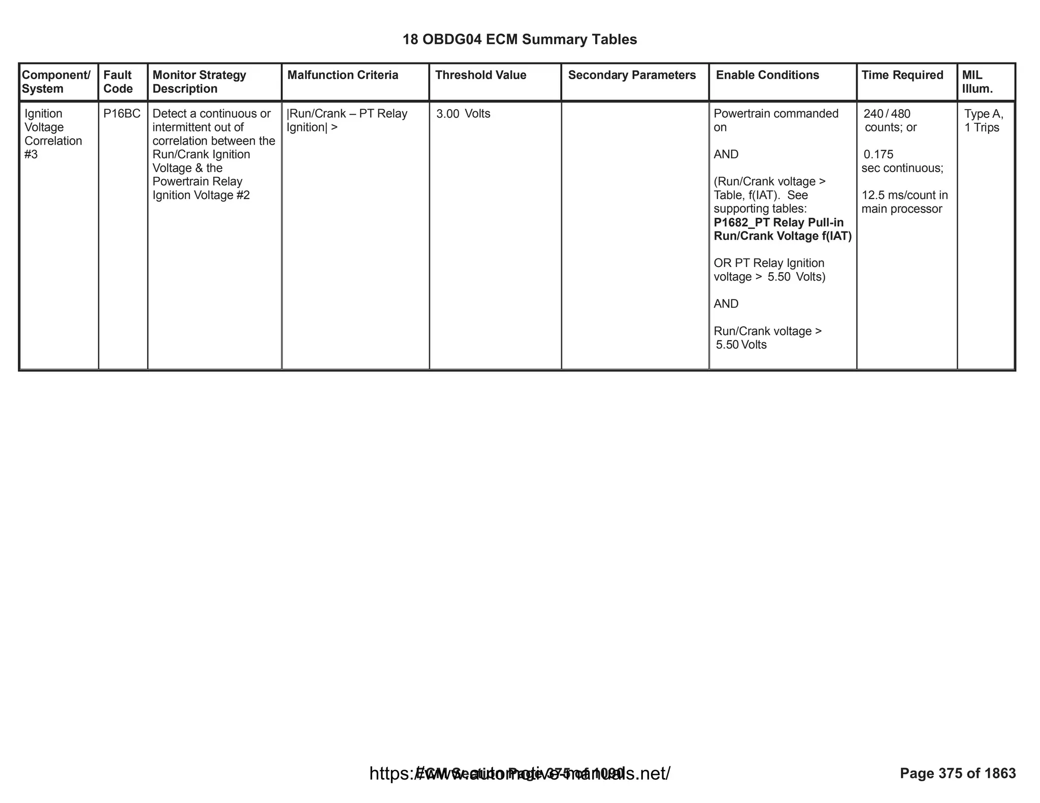

![Component/
System
Fault
Code
Monitor Strategy
Description
Malfunction Criteria Threshold Value Secondary Parameters Enable Conditions Time Required MIL
Illum.
Fuel Pump
Secondary C
ircuit
Performance
[FTZM
applications
only]
P2BB3 The FPDCM
periodically monitors
fuel pump duty cycle
control error. The
diagnostic detects
whether the pump
output duty cycle
[measured] value
differs too much
compared to the
received [commanded]
Fuel Pump Control
Duty Cycle.
Fuel Pump Duty Cycle
Command [Measured]
<> Fuel Pump Duty
Cycle Command
[Received]
a) Ignition Switch
Run_Crank Position
Circuit Voltage
b) Diagnostic enabled
c) CAN serial data
available [$0CB]
d) CAN serial data faulted
status [$0D9]
e) Fuel pump control
circuit faults [P0231,
P0232, P023F]
f) No fuel pump driver
over-temperature fault
[P1255]
g) Sensor Bus Relay On
h) Duty Cycle diagnostic
synchronization delay
time [expiration]
a) > volts
6.00
b) == True
c) == True
d) <> True
e) <> True
f) <> True
g) == True
h) > 100 milliseconds
12.5 millisec /
sample
Type A,
1 Trips
18 OBDG04 ECM Summary Tables
ECM Section Page 377 of 1090 Page 377 of 1863
https://www.automotive-manuals.net/](https://image.slidesharecdn.com/gmcenginefaultcodesdtc1-230327071418-56d3c5bb/75/18-OBDG04-ECM-Summary-Tables-377-2048.jpg)
![Component/
System
Fault
Code
Monitor Strategy
Description
Malfunction Criteria Threshold Value Secondary Parameters Enable Conditions Time Required MIL
Illum.
Charge Air
Cooler
Temperature
Sensor Up
Circuit
Performance
P007B This monitor checks if
the CAC up air
temperature sensor is
irrational at key on
when compared with
two reference
temperature sensors
after a long soak time
Charge air cooler up air
temperature is compared
at power up with an
average temperature
calculated using the
intake manifold air
temperature sensor and
the fuel temperature
sensor over a calibratable
number of samples
> [°C]
20.00 Test enabled by
calibration
Key on and engine not
running or engine running
for less than a calibratable
time
Runk Crank Relay voltage
in range
The engine has not run
for a calibratable time
since last key off
No faults detected on
engine off timer
Absolute value of the
difference between intake
manifold air temperature
and fuel temperature
smaller than a calibratable
threshold
No electrical or self-
correlated faults detected
on charge air cooler up air
temperature sensors
No faults detected on
intake manifold air
temperature sensor
== 1.00
>= [s]
0.10
> [V]
11.00
>= [s]
28,800.00
EngineModeNotRunTimer
Error
==FALSE
< [°C]
45.00
CIT_CAC_UpCktFA
==FALSE
CIT_CAC_UpSelfCorFA
==FALSE
MnfdTempSensorFA
==FALSE
Test executed
after a counter of
samples
1.00
Functional task:
100 ms
Type B,
2 Trips
18 OBDG04 ECM Summary Tables
ECM Section Page 378 of 1090 Page 378 of 1863
https://www.automotive-manuals.net/](https://image.slidesharecdn.com/gmcenginefaultcodesdtc1-230327071418-56d3c5bb/75/18-OBDG04-ECM-Summary-Tables-378-2048.jpg)
![Component/
System
Fault
Code
Monitor Strategy
Description
Malfunction Criteria Threshold Value Secondary Parameters Enable Conditions Time Required MIL
Illum.
Charge Air
Cooler
Temperature
Sensor Up
Circuit Low
P007C This monitor checks if
the CAC up air
temperature sensor is
out of electrical range
low
Charge air cooler up air
temperature resistance
value < low threshold
< [ohm]
55.00 Test enabled by
calibration
Engine not cranking
Runk Crank Relay voltage
in range
== 1.00
> [V]
11.00
fail
50.00
counter over
sample
63.00
counter
Functional task:
100 ms
Type B,
2 Trips
18 OBDG04 ECM Summary Tables
ECM Section Page 380 of 1090 Page 380 of 1863
https://www.automotive-manuals.net/](https://image.slidesharecdn.com/gmcenginefaultcodesdtc1-230327071418-56d3c5bb/75/18-OBDG04-ECM-Summary-Tables-380-2048.jpg)
![Component/
System
Fault
Code
Monitor Strategy
Description
Malfunction Criteria Threshold Value Secondary Parameters Enable Conditions Time Required MIL
Illum.
Charge Air
Cooler
Temperature
Sensor Up
Circuit High
P007D This monitor checks if
the CAC up air
temperature sensor is
out of electrical range
high
Charge air cooler up air
temperature resistance
value > high threshold
> [ohm]
100,605.00 Test enabled by
calibration
Engine not cranking
Runk Crank Relay voltage
in range
== 1.00
> [V]
11.00
fail
50.00
counter over
sample
63.00
counter
Functional task:
100 ms
Type B,
2 Trips
18 OBDG04 ECM Summary Tables
ECM Section Page 381 of 1090 Page 381 of 1863
https://www.automotive-manuals.net/](https://image.slidesharecdn.com/gmcenginefaultcodesdtc1-230327071418-56d3c5bb/75/18-OBDG04-ECM-Summary-Tables-381-2048.jpg)
![Component/
System
Fault
Code
Monitor Strategy
Description
Malfunction Criteria Threshold Value Secondary Parameters Enable Conditions Time Required MIL
Illum.
Charge Air
Cooler
Temperature
Sensor Up
Circuit
Intermittent/
Erratic
P007E This monitor checks if
the CAC up air
temperature has an
intermittent fault
Charge air cooler up air
temperature value >
T_MAX_threshold
Charge air cooler up air
temperature value <
T_MIN_threshold
where
- T_MAX_threshold = (1 -
alpha)*T_MAX +
alpha*T_last_good
- T_MIN_threshold = (1 -
alpha)*T_MIN +
alpha*T_last_good
- alpha = e^(#fails + 1)*(ts/
tau)
- #fails = number of
consecutive samples
where the test failed
- ts = sensor sampling
time
- tau = sensor filter
response time
- T_MAX = sensor
maximum actual reading
- T_MIN = sensor
minimum actual reading
- T_last_good = last good
temperature measured by
the sensor
> [°C]
300.00
< [°C]
-60.00
Test enabled by
calibration
Engine not cranking
Runk Crank Relay voltage
in range
No electrical faults
detected on CAC up air
temperature sensor
== 1.00
> [V]
11.00
CIT_CAC_UpCktFA
==FALSE
fail
50.00
counter over
sample
63.00
counter
Functional task:
100 ms
Type B,
2 Trips
18 OBDG04 ECM Summary Tables
ECM Section Page 382 of 1090 Page 382 of 1863
https://www.automotive-manuals.net/](https://image.slidesharecdn.com/gmcenginefaultcodesdtc1-230327071418-56d3c5bb/75/18-OBDG04-ECM-Summary-Tables-382-2048.jpg)
![Component/
System
Fault
Code
Monitor Strategy
Description
Malfunction Criteria Threshold Value Secondary Parameters Enable Conditions Time Required MIL
Illum.
Drift high check:
drift of the mass air flow
Drift low check:
drift of the mass air flow
The drift of the mass air
flow is calculated as the
ratio between the MAF
sensor reading and the
estimated mass air flow.
The ratio is averaged over
a calibrate-able
cumulative transient time.
If, by calibration,
CeMAFD_e_ArflRaw
==CeMAFD_e_ArflRaw,
the MAF sensor reading is
given by the raw MAF
value multiplied by the
P0101: Pulsation Map
> [ratio]
1.20
< [ratio]
0.80
Calibration on diagnostic
enabling
PT relay supply voltage in
range
Share High Side driver
closed
Estimated mass air flow is
valid
No Electrical or offset fault
present on MAF sensor
OBDII Market: Outside
Ambient Temperature in
range
OR
Fault present on Ouside
Air temperature
EOBD Market: Outside
Ambient Temperature in
range
AND
No Fault present on
Ouside Air temperature
P0101: MAF
performance enabling
==TRUE
> [V]
11.00
==TRUE
MAF_AirFlowEstdSS_Not
Vld
==FALSE
MAF_MAF_SnsrCktOffstF
A
==FALSE
MAF_MAF_SnsrCktOffstT
FKO
==FALSE
> [°C]
-7.00
==TRUE
OAT_PtEstFiltFA
> [°C]
-7.00
OAT_OAT_SnsrNonEmiss
FA
==FALSE
Test is evaluated
after the
enabling
conditions are
satisfied for a
number of
samples
== 400.00
Sampling time is:
12.5 ms
Mass Air
Flow (MAF)
Sensor
Performance
P0101 This monitor checks if
the MAF sensor
measure is coherent
with MAF estimation
when the HP EGR and
LP EGR (if present) are
closed.
It is able to detect MAF
sensor wiring harness
poor contacts, MAF
sensor internal fault
(offset), leaks from the
induction air circuit,
leaks from the
recirculation exhuast
gas circuit.
For OBDII market, it is
used to detect a PCV
disconnection.
The standard test can
be calibrated to run
when engine conditions
are recognised as
IDLE, OVERRUN or
HIGH LOAD.
An intrusive test can be
enabled, to force the
HP EGR to close when
particular conditions
are encountered, to
allow the monitoring to
run in idle.
Type B,
2 Trips
18 OBDG04 ECM Summary Tables
ECM Section Page 383 of 1090 Page 383 of 1863
https://www.automotive-manuals.net/](https://image.slidesharecdn.com/gmcenginefaultcodesdtc1-230327071418-56d3c5bb/75/18-OBDG04-ECM-Summary-Tables-383-2048.jpg)
![Component/
System
Fault
Code
Monitor Strategy
Description
Malfunction Criteria Threshold Value Secondary Parameters Enable Conditions Time Required MIL
Illum.
Induction air temperature
No fault present on
induction air temperature
sensor
(Engine Coolant
Temperature
OR
OBD Coolant Enable
Criteria),
AND
Engine Coolant
Temperature
No faults detected on
engine coolant
temperature sensor
Barometric pressure
No faults detected on
barometric pressure
sensor
Throttle valve position
No faults detected on
Throttle valve position
sensor
> [°C]
-25.00
==FALSE
IAT_SensorFA
IAT_SensorTFTKO
==FALSE
> [°C]
60.00
==TRUE
< [°C]
124.00
ECT_Sensor_FA
==FALSE
ECT_Sensor_TFTKO
==FALSE
> [kPa]
74.00
AAP_AmbientAirPresDfltd
==FALSE
AAP_AmbPresSnsrTFTK
O
==FALSE
> [%]
85.00
TPS_PstnSnsrFA
==FALSE
18 OBDG04 ECM Summary Tables
ECM Section Page 384 of 1090 Page 384 of 1863
https://www.automotive-manuals.net/](https://image.slidesharecdn.com/gmcenginefaultcodesdtc1-230327071418-56d3c5bb/75/18-OBDG04-ECM-Summary-Tables-384-2048.jpg)
![Component/
System
Fault
Code
Monitor Strategy
Description
Malfunction Criteria Threshold Value Secondary Parameters Enable Conditions Time Required MIL
Illum.
HP EGR valve position
No faults detected on HP
EGR valve position
sensor
LP EGR (if present) valve
position
No faults detected on LP
EGR (if present) valve
position sensor
Engine works in IDLE,
OVERRUN or HIGH
LOAD condition
<= [%]
2.00
EGR_PstnSnsrFA
==FALSE
<= [%]
0.00
LPE_PstnSnsrFA
==FALSE
Refer to "Engine
conditions" Free Form
Drift high check:
drift of the mass air flow
Drift low check:
drift of the mass air flow
The drift of the mass air
flow is calculated as the
ratio between the MAF
sensor reading and the
estimated mass air flow.
The ratio is averaged over
a calibrate-able
cumulative transient time.
If, by calibration,
CeMAFD_e_ArflRaw
> [ratio]
1.20
< [ratio]
0.80
Intrusive Test enabled by
calibration
MAF rationality monitoring
enabled by calibration
Diagnostic has not run in
current driving cycle yet
Calibratable SCR dosing
condition
==TRUE
0.00
P0101: MAF
performance enabling
==TRUE
==TRUE
IF ==TRUE: SCR
0.00
dosing condition is NH3
storage control OR
intrusive NH3 storage
control OR transient
dosing control.
Test is evaluated
after the
enabling
conditions are
satisfied for a
number of
samples
== 400.00
Sampling time is:
12.5 ms
18 OBDG04 ECM Summary Tables
ECM Section Page 385 of 1090 Page 385 of 1863
https://www.automotive-manuals.net/](https://image.slidesharecdn.com/gmcenginefaultcodesdtc1-230327071418-56d3c5bb/75/18-OBDG04-ECM-Summary-Tables-385-2048.jpg)
![Component/
System
Fault
Code
Monitor Strategy
Description
Malfunction Criteria Threshold Value Secondary Parameters Enable Conditions Time Required MIL
Illum.
==CeMAFD_e_ArflRaw,
the MAF sensor reading is
given by the raw MAF
value multiplied by the
P0101: Pulsation Map
SCR predicted NOx
conversion efficiency
Air control is working only
in EGR control: Desired
EGR rate
Vehicle speed
No faults detected on
vehicle speed sensor
PT relay supply voltage in
range
Share High Side driver
closed
Estimated mass air flow is
valid
No Electrical or offset fault
present on MAF sensor
IF ==FALSE: No
0.00
restrictions on SCR
dosing
> [ratio]
100.00
= 100%
< [kph]
260.00
VehicleSpeedSensor_FA
==FALSE
> [V]
11.00
==TRUE
MAF_AirFlowEstdSS_Not
Vld
==FALSE
MAF_MAF_SnsrCktOffstF
A
==FALSE
MAF_MAF_SnsrCktOffstT
FKO
==FALSE
18 OBDG04 ECM Summary Tables
ECM Section Page 386 of 1090 Page 386 of 1863
https://www.automotive-manuals.net/](https://image.slidesharecdn.com/gmcenginefaultcodesdtc1-230327071418-56d3c5bb/75/18-OBDG04-ECM-Summary-Tables-386-2048.jpg)
![Component/
System
Fault
Code
Monitor Strategy
Description
Malfunction Criteria Threshold Value Secondary Parameters Enable Conditions Time Required MIL
Illum.
OBDII Market: Outside
Ambient Temperature in
range
OR
Fault present on Ouside
Air temperature
EOBD Market: Outside
Ambient Temperature in
range
AND
No Fault present on
Ouside Air temperature
Induction air temperature
No fault present on
induction air temperature
sensor
(Engine Coolant
Temperature
OR
OBD Coolant Enable
Criteria),
AND
Engine Coolant
Temperature
No faults detected on
engine coolant
temperature sensor
Barometric pressure
> [°C]
-7.00
OR
==TRUE
OAT_PtEstFiltFA
> [°C]
-7.00
AND
OAT_OAT_SnsrNonEmiss
FA
==FALSE
> [°C]
-25.00
==FALSE
IAT_SensorFA
IAT_SensorTFTKO
==FALSE
> [°C]
60.00
==TRUE
< [°C]
124.00
ECT_Sensor_FA
==FALSE
ECT_Sensor_TFTKO
==FALSE
> [kPa]
74.00
18 OBDG04 ECM Summary Tables
ECM Section Page 387 of 1090 Page 387 of 1863
https://www.automotive-manuals.net/](https://image.slidesharecdn.com/gmcenginefaultcodesdtc1-230327071418-56d3c5bb/75/18-OBDG04-ECM-Summary-Tables-387-2048.jpg)
![Component/
System
Fault
Code
Monitor Strategy
Description
Malfunction Criteria Threshold Value Secondary Parameters Enable Conditions Time Required MIL
Illum.
No faults detected on
barometric pressure
sensor
Throttle valve position
No faults detected on
Throttle valve position
sensor
LP EGR (if present) valve
position
No faults detected on LP
EGR (if present) valve
position sensor
Engine speed in range
for a time
Intake manifold pressure
in range
Intake manifold pressure
is in steady state (SS)
AAP_AmbientAirPresDfltd
==FALSE
AAP_AmbPresSnsrTFTK
O
==FALSE
> [%]
85.00
TPS_PstnSnsrFA
==FALSE
<= [%]
0.00
LPE_PstnSnsrFA
==FALSE
> [rpm]
1,250.00
< [rpm]
1,200.00
>= [s]
1.00
> [kPa]
74.00
< [kPa]
120.00
when SS is OFF, the first
value of Intake manifold
pressure is taken as
reference (p_ref); then, |
Intake manifold pressure -
p_ref| < [kPa] for
10.00
18 OBDG04 ECM Summary Tables
ECM Section Page 388 of 1090 Page 388 of 1863
https://www.automotive-manuals.net/](https://image.slidesharecdn.com/gmcenginefaultcodesdtc1-230327071418-56d3c5bb/75/18-OBDG04-ECM-Summary-Tables-388-2048.jpg)
![Component/
System
Fault
Code
Monitor Strategy
Description
Malfunction Criteria Threshold Value Secondary Parameters Enable Conditions Time Required MIL
Illum.
Once all the conditions
above are satisfied,
additional conditions on
HP EGR valve must be
verified within a time limit
HP EGR valve position
No faults detected on HP
EGR valve position
sensor
All conditions are verified
for a time
maintaining the SS ON
< [s]
1.00
<= [%]
2.00
EGR_PstnSnsrFA
==FALSE
> [s]
1.00
18 OBDG04 ECM Summary Tables
ECM Section Page 389 of 1090 Page 389 of 1863
https://www.automotive-manuals.net/](https://image.slidesharecdn.com/gmcenginefaultcodesdtc1-230327071418-56d3c5bb/75/18-OBDG04-ECM-Summary-Tables-389-2048.jpg)
![Component/
System
Fault
Code
Monitor Strategy
Description
Malfunction Criteria Threshold Value Secondary Parameters Enable Conditions Time Required MIL
Illum.
Mass Air
Flow (MAF)
Sensor
Circuit Low
P0102 This monitor checks if
the MAF sensor is out
of electrical range low.
The MAF sensor is out
of electrical range low
in case of sensor
internal fault or wiring
harness faults.
MAF frequency value < [Hz]
276.00 Test enabled by
calibration
Engine speed
PT relay supply voltage in
range
Share High Side Driver
closed
All conditions are valid for
a time
==TRUE
1.00
>= [rpm]
50.00
> [V]
11.00
==TRUE
>= [s]
0.30
fail
100.00
counts
out of
sample
125.00
counts
Function task:
100 ms
Type B,
2 Trips
18 OBDG04 ECM Summary Tables
ECM Section Page 390 of 1090 Page 390 of 1863
https://www.automotive-manuals.net/](https://image.slidesharecdn.com/gmcenginefaultcodesdtc1-230327071418-56d3c5bb/75/18-OBDG04-ECM-Summary-Tables-390-2048.jpg)
![Component/
System
Fault
Code
Monitor Strategy
Description
Malfunction Criteria Threshold Value Secondary Parameters Enable Conditions Time Required MIL
Illum.
Mass Air
Flow (MAF)
Sensor
Circuit High
P0103 This monitor checks if
the MAF sensor is out
of electrical range high.
The MAF sensor is out
of electrical range high
in case of sensor
internal fault or wiring
harness faults.
MAF frequency value > [Hz]
12,500.00 Test enabled by
calibration
Engine speed
PT relay supply voltage in
range
Share High Side Driver
closed
All conditions arevalid for
a time
==TRUE
1.00
>= [rpm]
50.00
> [V]
11.00
==TRUE
>= [s]
0.30
100.00
fail counts
out of
sample
125.00
counts
Function
task:100 ms
Type B,
2 Trips
18 OBDG04 ECM Summary Tables
ECM Section Page 391 of 1090 Page 391 of 1863
https://www.automotive-manuals.net/](https://image.slidesharecdn.com/gmcenginefaultcodesdtc1-230327071418-56d3c5bb/75/18-OBDG04-ECM-Summary-Tables-391-2048.jpg)
![Component/
System
Fault
Code
Monitor Strategy
Description
Malfunction Criteria Threshold Value Secondary Parameters Enable Conditions Time Required MIL
Illum.
Fuel Trim
System Lean
Bank 1
P0171 This DTC monitors if
FSA control system has
reached its maximum
authority and cannot
achieve the target.
An error shall be
detected when the fuel
adjustment value
(mm3) released by FSA
is saturatedat its
minimum value.
Released FSA fuel
correction value
< refer to supporting
table (
KtFADC_V_FSA_Fuel
Min
) [mm3]
System voltage in range
FSA correction release
enabled
(FSA Learning is active
OR
DFSA Learning is active)
for a time
Ambient air pressure
OBD Coolant Enable
Criteria
OR
Engine coolant
temperature
Ambient air temperature
No Low fuel tank level
indication
No pending or confirmed
DTCs
> [V]
11.00
refer to "FSA Control
Flag" Free Form
FAD_FSA_NormRngCrtn
Valid
refer to "FSA Control
Flag" Free Form
(FAD_FSA_EnblLrn
OR
)
FAD_DFSA_EnblLrn
> [s]
1.00
> [kPa]
72.00
= TRUE
> [°C]
45.00
> [°C]
-7.00
LowFuelConditionDiagnos
tic
AmbPresDfltdStatus
(ECT_Sensor_TFTKO
AND
)
ECT_Sensor_FA
OAT_PtEstFiltFA
Time counter:
failures out
200
of samples.
400
Time task 25[ms]
Type B,
2 Trips
18 OBDG04 ECM Summary Tables
ECM Section Page 392 of 1090 Page 392 of 1863
https://www.automotive-manuals.net/](https://image.slidesharecdn.com/gmcenginefaultcodesdtc1-230327071418-56d3c5bb/75/18-OBDG04-ECM-Summary-Tables-392-2048.jpg)
![Component/
System
Fault
Code
Monitor Strategy
Description
Malfunction Criteria Threshold Value Secondary Parameters Enable Conditions Time Required MIL
Illum.
Fuel Trim
System Rich
Bank 1
P0172 This DTC monitors if
FSA control system has
reached its maximum
authority and cannot
achieve the target.
An error shall be
detected when the fuel
adjustment value
(mm3) released by FSA
is saturatedat its
maximum value.
Released FSA fuel
correction value
> refer to supporting
table
(
KtFADC_V_FSA_Fuel
Max
)[mm3]
System voltage in range
FSA correction release
enabled
(FSA Learning is active
OR
DFSA Learning is active)
for a time
Ambient air pressure
OBD Coolant Enable
Criteria
OR
Engine coolant
temperature
Ambient air temperature
No Low fuel tank level
indication
No pending or confirmed
DTCs
> [V]
11.00
refer to "FSA Control
Flag" Free Form
FAD_FSA_NormRngCrtn
Valid
refer to "FSA Control
Flag" Free Form
(FAD_FSA_EnblLrn
OR
)
FAD_DFSA_EnblLrn
> [s]
1.00
> [kPa]
72.00
= TRUE
> [°C]
45.00
> [°C]
-7.00
LowFuelConditionDiagnos
tic
AmbPresDfltdStatus
(ECT_Sensor_TFTKO
AND
)
ECT_Sensor_FA
OAT_PtEstFiltFA
Time counter:
failures out
200
of samples.
400
Time task 25[ms]
Type B,
2 Trips
18 OBDG04 ECM Summary Tables
ECM Section Page 393 of 1090 Page 393 of 1863
https://www.automotive-manuals.net/](https://image.slidesharecdn.com/gmcenginefaultcodesdtc1-230327071418-56d3c5bb/75/18-OBDG04-ECM-Summary-Tables-393-2048.jpg)
![Component/
System
Fault
Code
Monitor Strategy
Description
Malfunction Criteria Threshold Value Secondary Parameters Enable Conditions Time Required MIL
Illum.
Cylinder 1
Injection
Timing
Perfomance
- Over
Retarded
P01CB This diagnosis is able
to detect an excessive
negative drift on fuel
injection quantity and
timing affecting injector
1.
During Diesel Fuel Cut-
off conditions SQA
command the injection
of a known quantity on
one injector (e.g.
1,5mm^3) and checks,
by means of crank-
wheel sensor, the
angular acceleration
produced during the
combustion phase. By
comparing the angular
acceleration value
produced during the
combustion phase with
the angular
acceleration that would
be produced during the
combustion of a
nominal fuel quantity
(e.g. 1,5mm3), the SQA
is able to calculate the
drift, in term of
energizing time, on
injector 1.
Several injections, with
different injection
quantities, are
performed in order to
extrapolate the results
and obtain the injector
behaviour in the small
quantity area.
This energizing time is
then used for the
Suspicious confidence
level of tested injector (To
fail suspicious), function
of Current Energizing time
calculated with SSQA and
delta Energizing time
calculated in the previous
test:
KtFADD_Pct_SSQA_InjS
uspConfLvl
(Delta Enegizing Time,
Delta Energizing Time
old)
In case the first test fails:
Delta Energizing time
calculated with VSQA (To
fail Validation)
< [%]
50.00
> [us]
80.00
SQA Diagnosis enabled
SSQA and VSQA enabled
via calibration
Baro Pressure
Ambient temp
No Low Fuel level tank
indication
AND
Boolean Flag used to
enable low fuel level
check is TRUE
XSQA Learning conditions
enabled
Power Take Off not active
AND
Boolean Flag used to
disable SQA in case of
power take off active
1.00
1.00
>= [kPa]
74.00
>= [°C]
-7.00
LowFuelConditionDiagnos
tic
1.00
FAD_XSQA_LrnCondEnbl
= 0.00
Inj_To_PassFail_
SSQA Number of
injections in case
sospicious pass
or (if sospicious
fails)
Inj_To_PassFail_
SSQA
+Inj_To_PassFail
_VSQA number
of injections to
pass or fail
validation
Once per Trip if
suspicious and
validations (in
case of
sospicious
injectors
detected) have
been already
completed in the
previous driving
cycle, otherwise
the diagnosis
starts from the
interrupted
status.
Sample Rate: [1
Sample every
cylinder firing
event].
Type B,
2 Trips
18 OBDG04 ECM Summary Tables
ECM Section Page 394 of 1090 Page 394 of 1863
https://www.automotive-manuals.net/](https://image.slidesharecdn.com/gmcenginefaultcodesdtc1-230327071418-56d3c5bb/75/18-OBDG04-ECM-Summary-Tables-394-2048.jpg)


![Component/
System
Fault
Code
Monitor Strategy
Description
Malfunction Criteria Threshold Value Secondary Parameters Enable Conditions Time Required MIL
Illum.
Cylinder 1
Injection
Timing
Perfomance
- Over
Advanced
P01CC This diagnosis is able
to detect an excessive
positive drift on fuel
injection quantity and
timing affecting injector
1.
During Diesel Fuel Cut-
off conditions SQA
command the injection
of a known quantity on
one injector (e.g.
1,5mm^3) and checks,
by means of crank-
wheel sensor, the
angular acceleration
produced during the
combustion phase. By
comparing the angular
acceleration value
produced during the
combustion phase with
the angular
acceleration that would
be produced during the
combustion of a
nominal fuel quantity
(e.g. 1,5mm3), the SQA
is able to calculate the
drift, in term of
energizing time, on
injector 1.
Several injections, with
different injection
quantities, are
performed in order to
extrapolate the results
and obtain the injector
behaviour in the small
quantity area.
This energizing time is
then used for the
Suspicious confidence
level of tested injector (To
fail suspicious), function
of Current Energizing time
calculated with SSQA and
delta Energizing time
calculated in the previous
test:
KtFADD_Pct_SSQA_InjS
uspConfLvl
(Delta Enegizing Time,
Delta Energizing Time
old)
In case the first test fails:
Delta Energizing time
calculated with VSQA (To
fail Validation)
< [%]
50.00
< [us]
-90.00
SQA Diagnosis enabled
SSQA and VSQA enabled
via calibration
Baro Pressure
Ambient temp
No Low Fuel level tank
indication
AND
Boolean Flag used to
enable low fuel level
check is TRUE
XSQA Learning conditions
enabled
Power Take Off not active
AND
Boolean Flag used to
disable SQA in case of
power take off active
1.00
1.00
>= [kPa]
74.00
>= [°C]
-7.00
LowFuelConditionDiagnos
tic
1.00
FAD_XSQA_LrnCondEnbl
= 0.00
Inj_To_PassFail_
SSQA Number of
injections in case
sospicious pass
or (if sospicious
fails)
Inj_To_PassFail_
SSQA
+Inj_To_PassFail
_VSQA number
of injections to
pass or fail
validation
Once per Trip if
suspicious and
validations (in
case of
sospicious
injectors
detected) have
been already
completed in the
previous driving
cycle, otherwise
the diagnosis
starts from the
interrupted
status.
Sample Rate: [1
Sample every
cylinder firing
event].
Type B,
2 Trips
18 OBDG04 ECM Summary Tables
ECM Section Page 397 of 1090 Page 397 of 1863
https://www.automotive-manuals.net/](https://image.slidesharecdn.com/gmcenginefaultcodesdtc1-230327071418-56d3c5bb/75/18-OBDG04-ECM-Summary-Tables-397-2048.jpg)


![Component/
System
Fault
Code
Monitor Strategy
Description
Malfunction Criteria Threshold Value Secondary Parameters Enable Conditions Time Required MIL
Illum.
Cylinder 2
Injection
Timing
Perfomance
- Over
Retarded
P01CD This diagnosis is able
to detect an excessive
negative drift on fuel
injection quantity and
timing affecting injector
2.
During Diesel Fuel Cut-
off conditions SQA
command the injection
of a known quantity on
one injector (e.g.
1,5mm^3) and checks,
by means of crank-
wheel sensor, the
angular acceleration
produced during the
combustion phase. By
comparing the angular
acceleration value
produced during the
combustion phase with
the angular
acceleration that would
be produced during the
combustion of a
nominal fuel quantity
(e.g. 1,5mm3), the SQA
is able to calculate the
drift, in term of
energizing time, on
injector 2.
Several injections, with
different injection
quantities, are
performed in order to
extrapolate the results
and obtain the injector
behaviour in the small
quantity area.
This energizing time is
then used for the
Suspicious confidence
level of tested injector (To
fail suspicious), function
of Current Energizing time
calculated with SSQA and
delta Energizing time
calculated in the previous
test:
KtFADD_Pct_SSQA_InjS
uspConfLvl
(Delta Enegizing Time,
Delta Energizing Time
old)
In case the first test fails:
Delta Energizing time
calculated with VSQA (To
fail Validation)
< [%]
50.00
> [us]
80.00
SQA Diagnosis enabled
SSQA and VSQA enabled
via calibration
Baro Pressure
Ambient temp
No Low Fuel level tank
indication
AND
Boolean Flag used to
enable low fuel level
check is TRUE
XSQA Learning conditions
enabled
Power Take Off not active
AND
Boolean Flag used to
disable SQA in case of
power take off active
1.00
1.00
>= [kPa]
74.00
>= [°C]
-7.00
LowFuelConditionDiagnos
tic
1.00
FAD_XSQA_LrnCondEnbl
Inj_To_PassFail_
SSQA Number of
injections in case
sospicious pass
or (if sospicious
fails)
Inj_To_PassFail_
SSQA
+Inj_To_PassFail
_VSQA number
of injections to
pass or fail
validation
Once per Trip if
suspicious and
validations (in
case of
sospicious
injectors
detected) have
been already
completed in the
previous driving
cycle, otherwise
the diagnosis
starts from the
interrupted
status.
Sample Rate: [1
Sample every
cylinder firing
event].
Type B,
2 Trips
18 OBDG04 ECM Summary Tables
ECM Section Page 400 of 1090 Page 400 of 1863
https://www.automotive-manuals.net/](https://image.slidesharecdn.com/gmcenginefaultcodesdtc1-230327071418-56d3c5bb/75/18-OBDG04-ECM-Summary-Tables-400-2048.jpg)


![Component/
System
Fault
Code
Monitor Strategy
Description
Malfunction Criteria Threshold Value Secondary Parameters Enable Conditions Time Required MIL
Illum.
Cylinder 2
Injection
Timing
Perfomance
- Over
Advanced
P01CE This diagnosis is able
to detect an excessive
positive drift on fuel
injection quantity and
timing affecting injector
2.
During Diesel Fuel Cut-
off conditions SQA
command the injection
of a known quantity on
one injector (e.g.
1,5mm^3) and checks,
by means of crank-
wheel sensor, the
angular acceleration
produced during the
combustion phase. By
comparing the angular
acceleration value
produced during the
combustion phase with
the angular
acceleration that would
be produced during the
combustion of a
nominal fuel quantity
(e.g. 1,5mm3), the SQA
is able to calculate the
drift, in term of
energizing time, on
injector 2.
Several injections, with
different injection
quantities, are
performed in order to
extrapolate the results
and obtain the injector
behaviour in the small
quantity area.
This energizing time is
then used for the
Suspicious confidence
level of tested injector (To
fail suspicious), function
of Current Energizing time
calculated with SSQA and
delta Energizing time
calculated in the previous
test:
KtFADD_Pct_SSQA_InjS
uspConfLvl
(Delta Enegizing Time,
Delta Energizing Time
old)
In case the first test fails:
Delta Energizing time
calculated with VSQA (To
fail Validation)
< [%]
50.00
< [us]
-90.00
SQA Diagnosis enabled
SSQA and VSQA enabled
via calibration
Baro Pressure
Ambient temp
No Low Fuel level tank
indication
AND
Boolean Flag used to
enable low fuel level
check is TRUE
XSQA Learning conditions
enabled
1.00
1.00
>= [kPa]
74.00
>= [°C]
-7.00
LowFuelConditionDiagnos
tic
1.00
FAD_XSQA_LrnCondEnbl
Inj_To_PassFail_
SSQA Number of
injections in case
sospicious pass
or (if sospicious
fails)
Inj_To_PassFail_
SSQA
+Inj_To_PassFail
_VSQA number
of injections to
pass or fail
validation.
Once per Trip if
suspicious and
validations (in
case of
sospicious
injectors
detected) have
been already
completed in the
previous driving
cycle, otherwise
the diagnosis
starts from the
interrupted
status.
Sample Rate: [1
Sample every
cylinder firing
event].
Type B,
2 Trips
18 OBDG04 ECM Summary Tables
ECM Section Page 403 of 1090 Page 403 of 1863
https://www.automotive-manuals.net/](https://image.slidesharecdn.com/gmcenginefaultcodesdtc1-230327071418-56d3c5bb/75/18-OBDG04-ECM-Summary-Tables-403-2048.jpg)


![Component/
System
Fault
Code
Monitor Strategy
Description
Malfunction Criteria Threshold Value Secondary Parameters Enable Conditions Time Required MIL
Illum.
Cylinder 3
Injection
Timing
Perfomance
- Over
Retarded
P01CF This diagnosis is able
to detect an excessive
negative drift on fuel
injection quantity and
timing affecting injector
3.
During Diesel Fuel Cut-
off conditions SQA
command the injection
of a known quantity on
one injector (e.g.
1,5mm^3) and checks,
by means of crank-
wheel sensor, the
angular acceleration
produced during the
combustion phase. By
comparing the angular
acceleration value
produced during the
combustion phase with
the angular
acceleration that would
be produced during the
combustion of a
nominal fuel quantity
(e.g. 1,5mm3), the SQA
is able to calculate the
drift, in term of
energizing time, on
injector 3.
Several injections, with
different injection
quantities, are
performed in order to
extrapolate the results
and obtain the injector
behaviour in the small
quantity area.
This energizing time is
then used for the
Suspicious confidence
level of tested injector (To
fail suspicious), function
of Current Energizing time
calculated with SSQA and
delta Energizing time
calculated in the previous
test:
KtFADD_Pct_SSQA_InjS
uspConfLvl
(Delta Enegizing Time,
Delta Energizing Time
old)
In case the first test fails:
Delta Energizing time
calculated by VSQA (To
fail Validation)
< [%]
50.00
> [us]
80.00
SQA Diagnosis enabled
SSQA and VSQA enabled
via calibration
Baro Pressure
Ambient temp
No Low Fuel level tank
indication
AND
Boolean Flag used to
enable low fuel level
check is TRUE
XSQA Learning conditions
enabled
1.00
1.00
>= [kPa]
74.00
>= [°C]
-7.00
LowFuelConditionDiagnos
tic
1.00
FAD_XSQA_LrnCondEnbl
Inj_To_PassFail_
SSQA Number of
injections in case
sospicious pass
or (if sospicious
fails)
Inj_To_PassFail_
SSQA
+Inj_To_PassFail
_VSQA number
of injections to
pass or fail
validation
Once per Trip if
suspicious and
validations (in
case of
sospicious
injectors
detected) have
been already
completed in the
previous driving
cycle, otherwise
the diagnosis
starts from the
interrupted
status.
Sample Rate: [1
Sample every
cylinder firing
event].
Type B,
2 Trips
18 OBDG04 ECM Summary Tables
ECM Section Page 406 of 1090 Page 406 of 1863
https://www.automotive-manuals.net/](https://image.slidesharecdn.com/gmcenginefaultcodesdtc1-230327071418-56d3c5bb/75/18-OBDG04-ECM-Summary-Tables-406-2048.jpg)


![Component/
System
Fault
Code
Monitor Strategy
Description
Malfunction Criteria Threshold Value Secondary Parameters Enable Conditions Time Required MIL
Illum.
Cylinder 3
Injection
Timing
Perfomance
- Over
Advanced
P01D0 This diagnosis is able
to detect an excessive
positive drift on fuel
injection quantity and
timing affecting injector
3.
During Diesel Fuel Cut-
off conditions SQA
command the injection
of a known quantity on
one injector (e.g.
1,5mm^3) and checks,
by means of crank-
wheel sensor, the
angular acceleration
produced during the
combustion phase. By
comparing the angular
acceleration value
produced during the
combustion phase with
the angular
acceleration that would
be produced during the
combustion of a
nominal fuel quantity
(e.g. 1,5mm3), the SQA
is able to calculate the
drift, in term of
energizing time, on
injector 3.
Several injections, with
different injection
quantities, are
performed in order to
extrapolate the results
and obtain the injector
behaviour in the small
quantity area.
This energizing time is
then used for the
Suspicious confidence
level of tested injector (To
fail suspicious), function
of Current Energizing time
calculated with SSQA and
delta Energizing time
calculated in the previous
test:
KtFADD_Pct_SSQA_InjS
uspConfLvl
(Delta Enegizing Time,
Delta Energizing Time
old)
In case the first test fails:
Delta Energizing time
calculated by VSQA (To
fail Validation)
< [%]
50.00
< [us]
-90.00
SQA Diagnosis enabled
SSQA and VSQA enabled
Baro Pressure
Ambient temp
No Low Fuel level tank
indication
AND
Boolean Flag used to
enable low fuel level
check is TRUE
(x)SQA injection
management enabled
1.00
1.00
>= [kPa]
74.00
>= [°C]
-7.00
LowFuelConditionDiagnos
tic
1.00
FAD_XSQA_LrnCondEnbl
Inj_To_PassFail_
SSQA Number of
injections in case
sospicious pass
or (if sospicious
fails)
Inj_To_PassFail_
SSQA
+Inj_To_PassFail
_VSQA number
of injections to
pass or fail
validation.
Once per Trip if
suspicious and
validations (in
case of
sospicious
injectors
detected) have
been already
completed in the
previous driving
cycle, otherwise
the diagnosis
starts from the
interrupted
status.
Sample Rate: [1
Sample every
cylinder firing
event].
Type B,
2 Trips
18 OBDG04 ECM Summary Tables
ECM Section Page 409 of 1090 Page 409 of 1863
https://www.automotive-manuals.net/](https://image.slidesharecdn.com/gmcenginefaultcodesdtc1-230327071418-56d3c5bb/75/18-OBDG04-ECM-Summary-Tables-409-2048.jpg)


![Component/
System
Fault
Code
Monitor Strategy
Description
Malfunction Criteria Threshold Value Secondary Parameters Enable Conditions Time Required MIL
Illum.
Cylinder 4
Injection
Timing
Perfomance
- Over
Retarded
P01D1 This diagnosis is able
to detect an excessive
negative drift on fuel
injection quantity and
timing affecting injector
4.
During Diesel Fuel Cut-
off conditions SQA
command the injection
of a known quantity on
one injector (e.g.
1,5mm^3) and checks,
by means of crank-
wheel sensor, the
angular acceleration
produced during the
combustion phase. By
comparing the angular
acceleration value
produced during the
combustion phase with
the angular
acceleration that would
be produced during the
combustion of a
nominal fuel quantity
(e.g. 1,5mm3), the SQA
is able to calculate the
drift, in term of
energizing time, on
injector 4.
Several injections, with
different injection
quantities, are
performed in order to
extrapolate the results
and obtain the injector
behaviour in the small
quantity area.
This energizing time is
then used for the
Suspicious confidence
level of tested injector (To
fail suspicious), function
of Current Energizing time
calculated with SSQA and
delta Energizing time
calculated in the previous
test:
KtFADD_Pct_SSQA_InjS
uspConfLvl
(Delta Enegizing Time,
Delta Energizing Time
old)
In case the first test fails:
Delta Energizing time
calculated by VSQA (To
fail Validation)
< [%]
50.00
> [us]
80.00
SQA Diagnosis enabled
SSQA and VSQA enabled
Baro Pressure
Ambient temp
No Low Fuel level tank
indication
AND
Boolean Flag used to
enable low fuel level
check is TRUE
(x)SQA injection
management enabled
1.00
1.00
>= [kPa]
74.00
>= [°C]
-7.00
LowFuelConditionDiagnos
tic
1.00
FAD_XSQA_LrnCondEnbl
Inj_To_PassFail_
SSQA Number of
injections in case
sospicious pass
or (if sospicious
fails)
Inj_To_PassFail_
SSQA
+Inj_To_PassFail
_VSQA number
of injections to
pass or fail
validation
Once per Trip if
suspicious and
validations (in
case of
sospicious
injectors
detected) have
been already
completed in the
previous driving
cycle, otherwise
the diagnosis
starts from the
interrupted
status.
Sample Rate: [1
Sample every
cylinder firing
event].
Type B,
2 Trips
18 OBDG04 ECM Summary Tables
ECM Section Page 412 of 1090 Page 412 of 1863
https://www.automotive-manuals.net/](https://image.slidesharecdn.com/gmcenginefaultcodesdtc1-230327071418-56d3c5bb/75/18-OBDG04-ECM-Summary-Tables-412-2048.jpg)

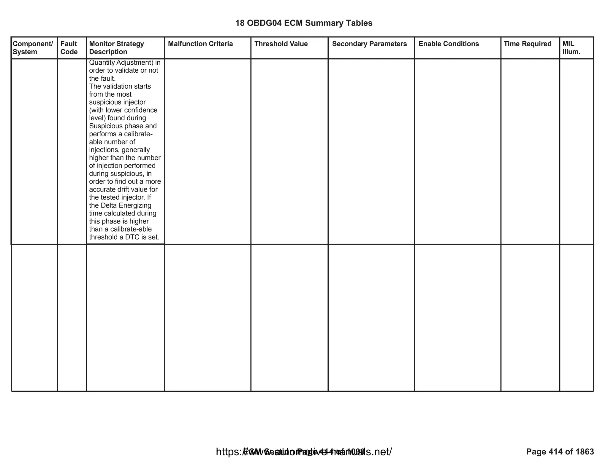
![Component/
System
Fault
Code
Monitor Strategy
Description
Malfunction Criteria Threshold Value Secondary Parameters Enable Conditions Time Required MIL
Illum.
Cylinder 4
Injection
Timing
Perfomance
- Over
Advanced
P01D2 This diagnosis is able
to detect an excessive
positive drift on fuel
injection quantity and
timing affecting injector
4.
During Diesel Fuel Cut-
off conditions SQA
command the injection
of a known quantity on
one injector (e.g.
1,5mm^3) and checks,
by means of crank-
wheel sensor, the
angular acceleration
produced during the
combustion phase. By
comparing the angular
acceleration value
produced during the
combustion phase with
the angular
acceleration that would
be produced during the
combustion of a
nominal fuel quantity
(e.g. 1,5mm3), the SQA
is able to calculate the
drift, in term of
energizing time, on
injector 4.
Several injections, with
different injection
quantities, are
performed in order to
extrapolate the results
and obtain the injector
behaviour in the small
quantity area.
This energizing time is
then used for the
Suspicious confidence
level of tested injector (To
fail suspicious), function
of Current Energizing time
calculated with SSQA and
delta Energizing time
calculated in the previous
test:
KtFADD_Pct_SSQA_InjS
uspConfLvl
(Delta Enegizing Time,
Delta Energizing Time
old)
In case the first test fails:
Delta Energizing time
calculated by VSQA (To
fail Validation)
< [%]
50.00
< [us]
-90.00
SQA Diagnosis enabled
SSQA and VSQA enabled
Baro Pressure
Ambient temp
No Low Fuel level tank
indication
AND
Boolean Flag used to
enable low fuel level
check is TRUE
(x)SQA injection
management enabled
1.00
1.00
>= [kPa]
74.00
>= [°C]
-7.00
LowFuelConditionDiagnos
tic
1.00
FAD_XSQA_LrnCondEnbl
Inj_To_PassFail_
SSQA Number of
injections in case
sospicious pass
or (if sospicious
fails)
Inj_To_PassFail_
SSQA
+Inj_To_PassFail
_VSQA number
of injections to
pass or fail
validation.
Once per Trip if
suspicious and
validations (in
case of
sospicious
injectors
detected) have
been already
completed in the
previous driving
cycle, otherwise
the diagnosis
starts from the
interrupted
status.
Sample Rate: [1
Sample every
cylinder firing
event].
Type B,
2 Trips
18 OBDG04 ECM Summary Tables
ECM Section Page 415 of 1090 Page 415 of 1863
https://www.automotive-manuals.net/](https://image.slidesharecdn.com/gmcenginefaultcodesdtc1-230327071418-56d3c5bb/75/18-OBDG04-ECM-Summary-Tables-415-2048.jpg)


![Component/
System
Fault
Code
Monitor Strategy
Description
Malfunction Criteria Threshold Value Secondary Parameters Enable Conditions Time Required MIL
Illum.
Injector 1
Open Circuit
(For 4
Cylinder
Engines)
P0201 This DTC checks the
Injector 1 circuit for
electrical integrity
during operation.
Low current through the
low side driver during
operation indicates open
circuit
Open circuit:
circuit attached to the
Controller external
connections has an
impedance >= 200 K
Ohm
Test enabled by
calibration;
and
Battery voltage
and
Key ON
and
Engine is not cranking
and
Engine Running
and
FUL_OutEnblCyl_CiEPS
R_CylinderA
and
At least one injection
pulse is requested by the
application software
(
FUL_FuelInjectedCyl_CiE
PSR_CylinderA
== [Boolean]
1
> [V]
11.00
-
-
>= [s]
1.00
== 0 [Boolean]
== TRUE);
failures out of
5
samples
10
100 ms/sample
Continuous
Type A,
1 Trips
18 OBDG04 ECM Summary Tables
ECM Section Page 418 of 1090 Page 418 of 1863
https://www.automotive-manuals.net/](https://image.slidesharecdn.com/gmcenginefaultcodesdtc1-230327071418-56d3c5bb/75/18-OBDG04-ECM-Summary-Tables-418-2048.jpg)
![Component/
System
Fault
Code
Monitor Strategy
Description
Malfunction Criteria Threshold Value Secondary Parameters Enable Conditions Time Required MIL
Illum.
Injector 2
Open Circuit
(For 4
Cylinder
Engines)
P0202 This DTC checks the
Injector 2 circuit for
electrical integrity
during operation.
Low current through the
low side driver during
operation indicates open
circuit
Open circuit:
circuit attached to the
Controller external
connections has an
impedance >= 200 K
Ohm
Test enabled by
calibration;
and
Battery voltage
and
Key ON
and
Engine is not cranking
and
Engine Running
and
FUL_OutEnblCyl_CiEPS
R_CylinderD
and
At least one injection
pulse is requested by the
application software
(
FUL_FuelInjectedCyl_CiE
PSR_CylinderD
== [Boolean]
1
> [V]
11.00
-
-
>= [s]
1.00
== 0 [Boolean]
== TRUE);
failures out of
5
samples
10
100 ms/sample
Continuous
Type A,
1 Trips
18 OBDG04 ECM Summary Tables
ECM Section Page 419 of 1090 Page 419 of 1863
https://www.automotive-manuals.net/](https://image.slidesharecdn.com/gmcenginefaultcodesdtc1-230327071418-56d3c5bb/75/18-OBDG04-ECM-Summary-Tables-419-2048.jpg)
![Component/
System
Fault
Code
Monitor Strategy
Description
Malfunction Criteria Threshold Value Secondary Parameters Enable Conditions Time Required MIL
Illum.
Injector 3
Open Circuit
(For 4
Cylinder
Engines)
P0203 This DTC checks the
Injector 3 circuit for
electrical integrity
during operation.
Low current through the
low side driver during
operation indicates open
circuit
Open circuit:
circuit attached to the
Controller external
connections has an
impedance >= 200 K
Ohm
Test enabled by
calibration;
and
Battery voltage
and
Key ON
and
Engine is not cranking
and
Engine Running
and
FUL_OutEnblCyl_CiEPS
R_CylinderB
and
At least one injection
pulse is requested by the
application software
(
FUL_FuelInjectedCyl_CiE
PSR_CylinderB
== [Boolean]
1
> [V]
11.00
-
-
>= [s]
1.00
== 0 [Boolean]
== TRUE);
failures out of
5
samples
10
100 ms/sample
Continuous
Type A,
1 Trips
18 OBDG04 ECM Summary Tables
ECM Section Page 420 of 1090 Page 420 of 1863
https://www.automotive-manuals.net/](https://image.slidesharecdn.com/gmcenginefaultcodesdtc1-230327071418-56d3c5bb/75/18-OBDG04-ECM-Summary-Tables-420-2048.jpg)
![Component/
System
Fault
Code
Monitor Strategy
Description
Malfunction Criteria Threshold Value Secondary Parameters Enable Conditions Time Required MIL
Illum.
Injector 4
Open Circuit
(For 4
Cylinder
Engines)
P0204 This DTC checks the
Injector 4 circuit for
electrical integrity
during operation.
Low current through the
low side driver during
operation indicates open
circuit
Open circuit:
circuit attached to the
Controller external
connections has an
impedance >= 200 K
Ohm
Test enabled by
calibration;
and
Battery voltage
and
Key ON
and
Engine is not cranking
and
Engine Running
and
FUL_OutEnblCyl_CiEPS
R_CylinderC
and
At least one injection
pulse is requested by the
application software
(
FUL_FuelInjectedCyl_CiE
PSR_CylinderC
== [Boolean]
1
> [V]
11.00
-
-
>= [s]
1.00
== 0 [Boolean]
== TRUE);
failures out of
5
samples
10
100 ms/sample
Continuous
Type A,
1 Trips
18 OBDG04 ECM Summary Tables
ECM Section Page 421 of 1090 Page 421 of 1863
https://www.automotive-manuals.net/](https://image.slidesharecdn.com/gmcenginefaultcodesdtc1-230327071418-56d3c5bb/75/18-OBDG04-ECM-Summary-Tables-421-2048.jpg)
![Component/
System
Fault
Code
Monitor Strategy
Description
Malfunction Criteria Threshold Value Secondary Parameters Enable Conditions Time Required MIL
Illum.
Cylinder 1
Injection
Timing (For
4 Cylinder
Engines)
P020A This DTC detects an
Injector fault or ECU
fault that causes pull In
period of the current
pulse out of range on
injector 1
The pull in period is the
time for the injection
current to rise to the
current level ( 17.50
[A]) at the beginning of
the pulse
Measurement of the Pull
In period of the current
pulse of the injector 1
provided by HWIO
< [us]
0.00
OR
> [us]
130.00
Test enabled by
calibration;
and
Battery voltage
and
Key ON
and
No active DTC's:
and
At least one injection
pulse is requested by the
application software
(
FUL_FuelInjectedCyl_CiE
PSR_CylinderA
and
No information of dropped
pulse reported by HWIO
== [Boolean]
1
> [V]
11.00
-
FUL_InjCktTFTKO
FUL_CntrlrStTFTKO
FUL_BoostVoltTFTKO
== TRUE);
-
failures out
10
of samples
20
1 sample every
engine cycle
Continuous
Type A,
1 Trips
18 OBDG04 ECM Summary Tables
ECM Section Page 422 of 1090 Page 422 of 1863
https://www.automotive-manuals.net/](https://image.slidesharecdn.com/gmcenginefaultcodesdtc1-230327071418-56d3c5bb/75/18-OBDG04-ECM-Summary-Tables-422-2048.jpg)
![Component/
System
Fault
Code
Monitor Strategy
Description
Malfunction Criteria Threshold Value Secondary Parameters Enable Conditions Time Required MIL
Illum.
Cylinder 2
Injection
Timing (For
4 Cylinder
Engines)
P020B This DTC detects an
Injector fault or ECU
fault that causes pull In
period of the current
pulse out of range on
injector 2
The pull in period is the
time for the injection
current to rise to the
current level ( 17.50
[A]) at the beginning of
the pulse
Measurement of the Pull
In period of the current
pulse of the injector 2
provided by HWIO
< [us]
0.00
OR
> [us]
130.00
Test enabled by
calibration;
and
Battery voltage
and
Key ON
and
No active DTC's:
and
At least one injection
pulse is requested by the
application software
(
FUL_FuelInjectedCyl_CiE
PSR_CylinderD
and
No information of dropped
pulse reported by HWIO
== [Boolean]
1
> [V]
11.00
-
FUL_InjCktTFTKO
FUL_CntrlrStTFTKO
FUL_BoostVoltTFTKO
== TRUE);
-
failures out
10
of samples
20
1 sample every
engine cycle
Continuous
Type A,
1 Trips
18 OBDG04 ECM Summary Tables
ECM Section Page 423 of 1090 Page 423 of 1863
https://www.automotive-manuals.net/](https://image.slidesharecdn.com/gmcenginefaultcodesdtc1-230327071418-56d3c5bb/75/18-OBDG04-ECM-Summary-Tables-423-2048.jpg)
![Component/
System
Fault
Code
Monitor Strategy
Description
Malfunction Criteria Threshold Value Secondary Parameters Enable Conditions Time Required MIL
Illum.
Cylinder 3
Injection
Timing (For
4 Cylinder
Engines)
P020C This DTC detects an
Injector fault or ECU
fault that causes pull In
period of the current
pulse out of range on
injector 3
The pull in period is the
time for the injection
current to rise to the
current level ( 17.50
[A]) at the beginning of
the pulse
Measurement of the Pull
In period of the current
pulse of the injector 3
provided by HWIO
< [us]
0.00
OR
> [us]
130.00
Test enabled by
calibration;
and
Battery voltage
and
Key ON
and
No active DTC's:
and
At least one injection
pulse is requested by the
application software;
(
FUL_FuelInjectedCyl_CiE
PSR_CylinderB
and
No information of dropped
pulse reported by HWIO
== [Boolean]
1
> [V]
11.00
-
FUL_InjCktTFTKO
FUL_CntrlrStTFTKO
FUL_BoostVoltTFTKO
== TRUE);
-
failures out
10
of samples
20
1 sample every
engine cycle
Continuous
Type A,
1 Trips
18 OBDG04 ECM Summary Tables
ECM Section Page 424 of 1090 Page 424 of 1863
https://www.automotive-manuals.net/](https://image.slidesharecdn.com/gmcenginefaultcodesdtc1-230327071418-56d3c5bb/75/18-OBDG04-ECM-Summary-Tables-424-2048.jpg)
![Component/
System
Fault
Code
Monitor Strategy
Description
Malfunction Criteria Threshold Value Secondary Parameters Enable Conditions Time Required MIL
Illum.
Cylinder 4
Injection
Timing (For
4 Cylinder
Engines)
P020D This DTC detects an
Injector fault or ECU
fault that causes pull In
period of the current
pulse out of range on
injector 4
The pull in period is the
time for the injection
current to rise to the
current level ( 17.50
[A]) at the beginning of
the pulse
Measurement of the Pull
In period of the current
pulse of the injector 4
provided by HWIO
< [us]
0.00
OR
> [us]
130.00
Test enabled by
calibration;
and
Battery voltage
and
Key ON
and
No active DTC's:
and
At least one injection
pulse is requested by the
application software;
(
FUL_FuelInjectedCyl_CiE
PSR_CylinderC
and
No information of dropped
pulse reported by HWIO
== [Boolean]
1
> [V]
11.00
-
FUL_InjCktTFTKO
FUL_CntrlrStTFTKO
FUL_BoostVoltTFTKO
== TRUE);
-
failures out
10
of samples
20
1 sample every
engine cycle
Continuous
Type A,
1 Trips
18 OBDG04 ECM Summary Tables
ECM Section Page 425 of 1090 Page 425 of 1863
https://www.automotive-manuals.net/](https://image.slidesharecdn.com/gmcenginefaultcodesdtc1-230327071418-56d3c5bb/75/18-OBDG04-ECM-Summary-Tables-425-2048.jpg)
![Component/
System
Fault
Code
Monitor Strategy
Description
Malfunction Criteria Threshold Value Secondary Parameters Enable Conditions Time Required MIL
Illum.
Injection
Timing
Control
Circuit
P0216 This DTC detects an
ECU internal fault, by
comparing the
cumulative injection
pulse width provided by
HWIO and the
cumulative injection
pulse width calculated
by Application SW.
A calibration is used to
define the pulses that
have to be taken into
account to calculate the
cumulative injection
pulse width, both by
HWIO and by
application SW.
Two different
thresholds are defined
for detecting the fault.
The high threshold
depends on the
number of injection
pulses active, i.e. the
injection pulses driven
and monitored.
The cumulative injection
pulse width (both HWIO
and Application SW) is
calculated by considering
only the pulses to be
monitored, defined in the
calibration
P0216_ET_CumulEnbl
if (Cumulative injection
pulse width read by
HWIO > Cumulative
injection pulse width
calculated by Application
SW)
{
|Cumulative injection
pulse width read by
HWIO -
Cumulative injection pulse
width calculated by
Application SW|
}
else
{
|Cumulative injection
pulse width read by
HWIO -
Cumulative injection pulse
width calculated by
Application SW|
}
Cumulative injection pulse
width calculated by
Application SW is equal to
the sum of the
programmed pulses width
and the end of injection
period measurement
>
P0216_PulsWidthErr
Hi
[us] depending on the
number of injection
pulses active
> [us]
32,767.00
Test enabled by
calibration;
and
Battery voltage
and
Key ON
and
No active DTC's:
and
At least one Injection
Pulse is requested by the
application software
(FUL_FuelInjected
and
No information of dropped
pulse reported by HWIO
== [Boolean]
1.00
> [V]
11.00
-
FUL_InjCktTFTKO
FUL_CntrlrStTFTKO
FUL_BoostVoltTFTKO
FUL_PullInErrTFTKO
== TRUE);
-
failures out
30
of samples
124
or
consecutive
60
failures
1 sample every
cylinder firing
Continuous
Type A,
1 Trips
18 OBDG04 ECM Summary Tables
ECM Section Page 426 of 1090 Page 426 of 1863
https://www.automotive-manuals.net/](https://image.slidesharecdn.com/gmcenginefaultcodesdtc1-230327071418-56d3c5bb/75/18-OBDG04-ECM-Summary-Tables-426-2048.jpg)
![Component/
System
Fault
Code
Monitor Strategy
Description
Malfunction Criteria Threshold Value Secondary Parameters Enable Conditions Time Required MIL
Illum.
Injector 1
Control
Circuit Low
Voltage (For
4 Cylinder
Engines)
P0261 This DTC detects a
short circuit to ground
of the low side driver
circuit of Injector 1.
Voltage low across low
side drive during off state
indicates short-to-ground
Short to ground:
impedence between
LS pin and controller
ground <= 0.5 [Ohm]
Test enabled by
calibration;
and
Battery voltage
and
Key ON
and
Engine is not cranking
and
Engine Running
and
FUL_OutEnblCyl_CiEPS
R_CylinderA
and
At least one injection
pulse is requested by the
application software
(
FUL_FuelInjectedCyl_CiE
PSR_CylinderA
== [Boolean]
1
> [V]
11.00
-
-
>= [s]
1.00
== 0 [Boolean]
== TRUE);
failures out of
5
samples
10
100 ms/sample
Continuous
Type A,
1 Trips
18 OBDG04 ECM Summary Tables
ECM Section Page 428 of 1090 Page 428 of 1863
https://www.automotive-manuals.net/](https://image.slidesharecdn.com/gmcenginefaultcodesdtc1-230327071418-56d3c5bb/75/18-OBDG04-ECM-Summary-Tables-428-2048.jpg)
![Component/
System
Fault
Code
Monitor Strategy
Description
Malfunction Criteria Threshold Value Secondary Parameters Enable Conditions Time Required MIL
Illum.
Injector 1
Control
Circuit High
Voltage (For
4 Cylinder
Engines)
P0262 This DTC detects a
short circuit to power
supply of the low side
driver circuit of Injector
1
Voltage high across low
side driver during On
state indicates short to
power
Short to power:
impedence between
LS pin and controller
power <= 0.5 [Ohm]
Test enabled by
calibration;
and
Battery voltage
and
Key ON
and
Engine is not cranking
and
Engine Running
and
FUL_OutEnblCyl_CiEPS
R_CylinderA
and
At least one injection
pulse is requested by the
application software
(
FUL_FuelInjectedCyl_CiE
PSR_CylinderA
== [Boolean]
1
> [V]
11.00
-
-
>= [s]
1.00
== 0 [Boolean]
== TRUE);
failures out of
5
samples
10
100 ms/sample
Continuous
Type A,
1 Trips
18 OBDG04 ECM Summary Tables
ECM Section Page 429 of 1090 Page 429 of 1863
https://www.automotive-manuals.net/](https://image.slidesharecdn.com/gmcenginefaultcodesdtc1-230327071418-56d3c5bb/75/18-OBDG04-ECM-Summary-Tables-429-2048.jpg)
![Component/
System
Fault
Code
Monitor Strategy
Description
Malfunction Criteria Threshold Value Secondary Parameters Enable Conditions Time Required MIL
Illum.
Cylinder
Balance 1
Maximum
Authority
Reached
P0263 The Cylinder Balancing
(CB) strategy is able to
get a cylinder by
cylinder external torque
equalization to improve
engine smooth running
(less engine speed
roughness, more
driving comfort)..
The Cylinder Balancing
uses as input of the
closed loop the
unbalancing signal and
provide, as output, the
fuel volume correction
to apply on each
cylinder. The target of
the closed loop is to get
zero unbalancing on all
cylinders. The
unbalancing signal
cointains the torque
formed during the
combustion phase of
each cylinder.
This diagnosis is able
to detect if Cylinder
Balancing fuel volume
correctionapplied on
cylinder 1 reach the
saturation (positive or
negative) without
achieve the target (zero
unbalancing).
When CB correction for
cylinder 1 reach the
saturation (positive or
negative) the CB
control system sets a
Boolean flag to true in
order to inform the Max
Cylinder Balancing Fuel
Volume Correction on
cylinder 1 saturated
(positive or negative).
FAD_CB_Cyl_A_HiSat
urated
==TRUE
OR
FAD_CB_Cyl_A_LoSat
urated
==TRUE
Test enabled by
calibration
No faults detected on
injectors
Fuel Injector Disable
Device Control not active
CB enabled in closed loop
EOL injector codes written
No errors related to
redundant calculation of
EOL injector codes
No Low fuel tank level
indication
Fuel request higher than a
calibrateable threshold
(OBD Coolant Enable
Criteria
OR
Engine coolant
temperature higher than a
calibrateable threshold)
No faults on Engine
coolant temperature
sensor.
1.00
FUL_GenericInjSysFlt
FUL_InjectorDisable
FAD_CB_CntrlType
==CeFADC_e_CB_CL_E
nbl
FAD_EIA_DID_Written
FAD_EIA_RedntFlt
LowFuelConditionDiagnos
tic
>= [mm3/stroke]
15.00
==TRUE
>= [°C]
-20.00
(ECT_Sensor_TFTKO
AND
)
ECT_Sensor_FA
Fails
125.00
Samples over
samples.
175.00
1 sample every
cylinder firing
event.
Type B,
2 Trips
18 OBDG04 ECM Summary Tables
ECM Section Page 430 of 1090 Page 430 of 1863
https://www.automotive-manuals.net/](https://image.slidesharecdn.com/gmcenginefaultcodesdtc1-230327071418-56d3c5bb/75/18-OBDG04-ECM-Summary-Tables-430-2048.jpg)
![Component/
System
Fault
Code
Monitor Strategy
Description
Malfunction Criteria Threshold Value Secondary Parameters Enable Conditions Time Required MIL
Illum.
Injector 2
Control
Circuit Low
Voltage (For
4 Cylinder
Engines)
P0264 This DTC detects a
short circuit to ground
of the low side driver
circuit of Injector 2.
Voltage low across low
side drive during off state
indicates short-to-ground
Short to ground:
impedence between
LS pin and controller
ground <= 0.5 [Ohm]
Test enabled by
calibration;
and
Battery voltage
and
Key ON
and
Engine is not cranking
and
Engine Running
and
FUL_OutEnblCyl_CiEPS
R_CylinderD
and
At least one injection
pulse is requested by the
application software
(
FUL_FuelInjectedCyl_CiE
PSR_CylinderD
== [Boolean]
1
> [V]
11.00
-
-
>= [s]
1.00
== 0 [Boolean]
== TRUE);
failures out of
5
samples
10
100 ms/sample
Continuous
Type A,
1 Trips
18 OBDG04 ECM Summary Tables
ECM Section Page 432 of 1090 Page 432 of 1863
https://www.automotive-manuals.net/](https://image.slidesharecdn.com/gmcenginefaultcodesdtc1-230327071418-56d3c5bb/75/18-OBDG04-ECM-Summary-Tables-432-2048.jpg)
![Component/
System
Fault
Code
Monitor Strategy
Description
Malfunction Criteria Threshold Value Secondary Parameters Enable Conditions Time Required MIL
Illum.
Injector 2
Control
Circuit High
Voltage (For
4 Cylinder
Engines)
P0265 This detects a short
circuit to power supply
of the low side driver
circuit of Injector 2.
Voltage high across low
side driver during On
state indicates short to
power
Short to power:
impedence between
LS pin and controller
power <= 0.5 [Ohm]
Test enabled by
calibration;
and
Battery voltage
and
Key ON
and
Engine is not cranking
and
Engine Running
and
FUL_OutEnblCyl_CiEPS
R_CylinderD
and
At least one injection
pulse is requested by the
application software
(
FUL_FuelInjectedCyl_CiE
PSR_CylinderD
== [Boolean]
1
> [V]
11.00
-
-
>= [s]
1.00
== 0 [Boolean]
== TRUE);
5
failures out of
10
samples
100 ms/sample
Continuous
Type A,
1 Trips
18 OBDG04 ECM Summary Tables
ECM Section Page 433 of 1090 Page 433 of 1863
https://www.automotive-manuals.net/](https://image.slidesharecdn.com/gmcenginefaultcodesdtc1-230327071418-56d3c5bb/75/18-OBDG04-ECM-Summary-Tables-433-2048.jpg)
![Component/
System
Fault
Code
Monitor Strategy
Description
Malfunction Criteria Threshold Value Secondary Parameters Enable Conditions Time Required MIL
Illum.
Cylinder
Balance 2
Maximum
Authority
Reached
P0266 The Cylinder Balancing
(CB) strategy is able to
get a cylinder by
cylinder external torque
equalization to improve
engine smooth running
(less engine speed
roughness, more
driving comfort)..
The Cylinder Balancing
uses as input of the
closed loop the
unbalancing signal and
provide, as output, the
fuel volume correction
to apply on each
cylinder. The target of
the closed loop is to get
zero unbalancing on all
cylinders. The
unbalancing signal
cointains the torque
formed during the
combustion phase of
each cylinder.
This diagnosis is able
to detect if Cylinder
Balancing fuel volume
correctionapplied on
cylinder 2 reach the
saturation (positive or
negative) without
achieve the target (zero
unbalancing).
When CB correction for
cylinder 2 reach the
saturation (positive or
negative) the CB
control system sets a
Boolean flag to true in
order to inform the Max
Cylinder Balancing Fuel
Volume Correction on
cylinder 2 saturated
(positive or negative).
FAD_CB_Cyl_D_HiSat
urated
==TRUE
OR
FAD_CB_Cyl_D_LoSat
urated
==TRUE
Test enabled by
calibration
No faults detected on
injectors
Fuel Injector Disable
Device Control not active
CB enabled in closed loop
EOL injector codes written
No errors related to
redundant calculation of
EOL injector codes
No Low fuel tank level
indication
Fuel request higher than a
calibrateable threshold
(OBD Coolant Enable
Criteria
OR
Engine coolant
temperature higher than a
calibrateable threshold)
No faults on Engine
coolant temperature
sensor.
1.00
FUL_GenericInjSysFlt
FUL_InjectorDisable
FAD_CB_CntrlType
==CeFADC_e_CB_CL_E
nbl
FAD_EIA_DID_Written
FAD_EIA_RedntFlt
LowFuelConditionDiagnos
tic
>= [mm3/stroke]
15.00
==TRUE
>= [°C]
-20.00
(ECT_Sensor_TFTKO
AND
)
ECT_Sensor_FA
Fail
125.00
Samples over
samples.
175.00
1 sample every
cylinder firing
event.
Type B,
2 Trips
18 OBDG04 ECM Summary Tables
ECM Section Page 434 of 1090 Page 434 of 1863
https://www.automotive-manuals.net/](https://image.slidesharecdn.com/gmcenginefaultcodesdtc1-230327071418-56d3c5bb/75/18-OBDG04-ECM-Summary-Tables-434-2048.jpg)

![Component/
System
Fault
Code
Monitor Strategy
Description
Malfunction Criteria Threshold Value Secondary Parameters Enable Conditions Time Required MIL
Illum.
Injector 3
Control
Circuit Low
Voltage (For
4 Cylinder
Engines)
P0267 This DTC detects a
short circuit to ground
of the low side driver
circuit of Injector 3.
Voltage low across low
side drive during off state
indicates short-to-ground
Short to ground:
impedence between
LS pin and controller
ground <= 0.5 [Ohm]
Test enabled by
calibration;
and
Battery voltage
and
Key ON
and
Engine is not cranking
and
Engine Running
and
FUL_OutEnblCyl_CiEPS
R_CylinderB
and
At least one injection
pulse is requested by the
application software
(
FUL_FuelInjectedCyl_CiE
PSR_CylinderB
== [Boolean]
1
> [V]
11.00
-
-
>= [s]
1.00
== 0 [Boolean]
== TRUE);
failures out of
5
samples
10
100 ms/sample
Continuous
Type A,
1 Trips
18 OBDG04 ECM Summary Tables
ECM Section Page 436 of 1090 Page 436 of 1863
https://www.automotive-manuals.net/](https://image.slidesharecdn.com/gmcenginefaultcodesdtc1-230327071418-56d3c5bb/75/18-OBDG04-ECM-Summary-Tables-436-2048.jpg)
![Component/
System
Fault
Code
Monitor Strategy
Description
Malfunction Criteria Threshold Value Secondary Parameters Enable Conditions Time Required MIL
Illum.
Injector 3
Control
Circuit High
Voltage (For
4 Cylinder
Engines)
P0268 This DTC detects a
short circuit to power
supply of the low side
driver circuit of Injector
3.
Voltage high across low
side driver during On
state indicates short to
power
Short to power:
impedence between
LS pin and controller
power <= 0.5 [Ohm]
Test enabled by
calibration;
and
Battery voltage
and
Key ON
and
Engine is not cranking
and
Engine Running
and
FUL_OutEnblCyl_CiEPS
R_CylinderB
and
At least one injection
pulse is requested by the
application software
(
FUL_FuelInjectedCyl_CiE
PSR_CylinderB
== [Boolean]
1
> [V]
11.00
-
-
>= [s]
1.00
== 0 [Boolean]
== TRUE);
5
failures out of
10
samples
100 ms/sample
Continuous
Type A,
1 Trips
18 OBDG04 ECM Summary Tables
ECM Section Page 437 of 1090 Page 437 of 1863
https://www.automotive-manuals.net/](https://image.slidesharecdn.com/gmcenginefaultcodesdtc1-230327071418-56d3c5bb/75/18-OBDG04-ECM-Summary-Tables-437-2048.jpg)
![Component/
System
Fault
Code
Monitor Strategy
Description
Malfunction Criteria Threshold Value Secondary Parameters Enable Conditions Time Required MIL
Illum.
Cylinder
Balance 3
Maximum
Authority
Reached
P0269 The Cylinder Balancing
(CB) strategy is able to
get a cylinder by
cylinder external torque
equalization to improve
engine smooth running
(less engine speed
roughness, more
driving comfort)..
The Cylinder Balancing
uses as input of the
closed loop the
unbalancing signal and
provide, as output, the
fuel volume correction
to apply on each
cylinder. The target of
the closed loop is to get
zero unbalancing on all
cylinders. The
unbalancing signal
cointains the torque
formed during the
combustion phase of
each cylinder.
This diagnosis is able
to detect if Cylinder
Balancing fuel volume
correctionapplied on
cylinder 3 reach the
saturation (positive or
negative) without
achieve the target (zero
unbalancing).
When CB correction for
cylinder 3 reach the
saturation (positive or
negative) the CB
control system sets a
Boolean flag to true in
order to inform the Max
Cylinder Balancing Fuel
Volume Correction on
cylinder 3 saturated
(positive or negative).
FAD_CB_Cyl_B_HiSat
urated
==TRUE
OR
FAD_CB_Cyl_B_LoSat
urated
==TRUE
Test enabled by
calibration
No faults detected on
injectors
Fuel Injector Disable
Device Control not active
CB enabled in closed loop
EOL injector codes written
No errors related to
redundant calculation of
EOL injector codes
No Low fuel tank level
indication
Fuel request higher than a
calibrateable threshold
(OBD Coolant Enable
Criteria
OR
Engine coolant
temperature higher than a
calibrateable threshold )
No faults on Engine
coolant temperature
sensor.
1.00
FUL_GenericInjSysFlt
FUL_InjectorDisable
FAD_CB_CntrlType
==CeFADC_e_CB_CL_E
nbl
FAD_EIA_DID_Written
FAD_EIA_RedntFlt
LowFuelConditionDiagnos
tic
>= [mm3/stroke]
15.00
==TRUE
>= [°C]
-20.00
(ECT_Sensor_TFTKO
AND
)
ECT_Sensor_FA
Fail
125.00
Samples over
samples.
175.00
1 sample every
cylinder firing
event.
Type B,
2 Trips
18 OBDG04 ECM Summary Tables
ECM Section Page 438 of 1090 Page 438 of 1863
https://www.automotive-manuals.net/](https://image.slidesharecdn.com/gmcenginefaultcodesdtc1-230327071418-56d3c5bb/75/18-OBDG04-ECM-Summary-Tables-438-2048.jpg)

![Component/
System
Fault
Code
Monitor Strategy
Description
Malfunction Criteria Threshold Value Secondary Parameters Enable Conditions Time Required MIL
Illum.
Charge Air
Cooler
Efficiency
Below
Threshold
(OBDII
market only)
P026A This monitor checks
the Charge Air Cooler
efficiency deterioration,
that would cause
vehicle's emissions to
exceed specific
emission levels.
Charge Air Cooler
Efficiency (averaged over
a calibrate-able
cumulative transient time)
is compared with a
threshold.
Charge Air Cooler
Efficiency is computed as
the ratio between (CAC
upstream temperature -
CAC downstream
temperature) and (CAC
upstream temperature -
Ambient air temperature).
< [%]
50.00 Calibration on diagnostic
enabling
Diagnostic has not run in
current driving cycle yet
Vehicle speed in range
Air mass flow in range
Engine coolant
temperature in range
OR
OBD Coolant Enable
Criteria
Throttle valve position
Pressure ratio through the
compressor in range
Temperature difference
between upstream charge
air cooler and ambient
temperature in range
Environmental pressure in
range
Environmental
temperature in range
==TRUE
1.00
==TRUE
> [kph]
60.00
> [mg/s]
10.00
< [mg/s]
100.00
> [°C]
60.00
==TRUE
> [%]
90.00
> [ratio]
0.00
> [°C]
10.00
> [kPa]
74.80
> [°C]
-7.00
Test executed
after 200.00
samples are
collected and
their average is
computed
Function task:
100 ms
Type B,
2 Trips
18 OBDG04 ECM Summary Tables
ECM Section Page 440 of 1090 Page 440 of 1863
https://www.automotive-manuals.net/](https://image.slidesharecdn.com/gmcenginefaultcodesdtc1-230327071418-56d3c5bb/75/18-OBDG04-ECM-Summary-Tables-440-2048.jpg)
![Component/
System
Fault
Code
Monitor Strategy
Description
Malfunction Criteria Threshold Value Secondary Parameters Enable Conditions Time Required MIL
Illum.
No fault on vehicle speed
sensor
No fault on engine
coolant temperature
sensor
No fault on throttle
position sensor
No fault on ambient
pressure sensor
No fault on ambient
temperature sensor
No fault on charge air
cooler upstream and
downstream temperature
sensors
No fault on MAF meter
No fault on Intake
Manifold Pressure sensor
All the enabling conditions
last for a time
VehicleSpeedSensor_FA
==FALSE
ECT_Sensor_FA
==FALSE
TPS_PstnSnsrFA
==FALSE
AAP_AmbientAirPresDfltd
==FALSE
OAT_PtEstFiltFA
==FALSE
==FALSE
CIT_CAC_UpFA
CIT_CAC_DwnFA
==FALSE
MAF_MAF_SnsrFA
==FALSE
==FALSE
MAP_SensorFA
>= [s]
1.00
18 OBDG04 ECM Summary Tables
ECM Section Page 441 of 1090 Page 441 of 1863
https://www.automotive-manuals.net/](https://image.slidesharecdn.com/gmcenginefaultcodesdtc1-230327071418-56d3c5bb/75/18-OBDG04-ECM-Summary-Tables-441-2048.jpg)
![Component/
System
Fault
Code
Monitor Strategy
Description
Malfunction Criteria Threshold Value Secondary Parameters Enable Conditions Time Required MIL
Illum.
Injector 4
Control
Circuit Low
Voltage (For
4 Cylinder
Engines)
P0270 This DTC detects a
short circuit to ground
of the low side driver
circuit of Injector 4.
Voltage low across low
side drive during off state
indicates short-to-ground
Short to ground:
impedence between
LS pin and controller
ground <= 0.5 [Ohm]
Test enabled by
calibration;
and
Battery voltage
and
Key ON
and
Engine is not cranking
and
Engine Running
and
FUL_OutEnblCyl_CiEPS
R_CylinderC
and
At least one injection
pulse is requested by the
application software
(
FUL_FuelInjectedCyl_CiE
PSR_CylinderC
== [Boolean]
1
> [V]
11.00
-
-
>= [s]
1.00
== 0 [Boolean]
== TRUE);
failures out of
5
samples
10
100 ms/sample
Continuous
Type A,
1 Trips
18 OBDG04 ECM Summary Tables
ECM Section Page 442 of 1090 Page 442 of 1863
https://www.automotive-manuals.net/](https://image.slidesharecdn.com/gmcenginefaultcodesdtc1-230327071418-56d3c5bb/75/18-OBDG04-ECM-Summary-Tables-442-2048.jpg)
![Component/
System
Fault
Code
Monitor Strategy
Description
Malfunction Criteria Threshold Value Secondary Parameters Enable Conditions Time Required MIL
Illum.
Injector 4
Control
Circuit High
Voltage (For
4 Cylinder
Engines)
P0271 This DTC detects a
short circuit to power
supply of the low side
driver circuit of Injector
4.
Voltage high across low
side driver during On
state indicates short to
power
Short to power:
impedence between
LS pin and controller
power <= 0.5 [Ohm]
Test enabled by
calibration;
and
Battery voltage
and
Key ON
and
Engine is not cranking
and
Engine Running
and
FUL_OutEnblCyl_CiEPS
R_CylinderC
and
At least one injection
pulse is requested by the
application software
(
FUL_FuelInjectedCyl_CiE
PSR_CylinderC
== [Boolean]
1
> [V]
11.00
-
-
>= [s]
1.00
== 0 [Boolean]
== TRUE);
5
failures out of
10
samples
100 ms/sample
Continuous
Type A,
1 Trips
18 OBDG04 ECM Summary Tables
ECM Section Page 443 of 1090 Page 443 of 1863
https://www.automotive-manuals.net/](https://image.slidesharecdn.com/gmcenginefaultcodesdtc1-230327071418-56d3c5bb/75/18-OBDG04-ECM-Summary-Tables-443-2048.jpg)
![Component/
System
Fault
Code
Monitor Strategy
Description
Malfunction Criteria Threshold Value Secondary Parameters Enable Conditions Time Required MIL
Illum.
Cylinder
Balance 4
Maximum
Authority
Reached
P0272 The Cylinder Balancing
(CB) strategy is able to
get a cylinder by
cylinder external torque
equalization to improve
engine smooth running
(less engine speed
roughness, more
driving comfort)..
The Cylinder Balancing
uses as input of the
closed loop the
unbalancing signal and
provide, as output, the
fuel volume correction
to apply on each
cylinder. The target of
the closed loop is to get
zero unbalancing on all
cylinders. The
unbalancing signal
cointains the torque
formed during the
combustion phase of
each cylinder.
This diagnosis is able
to detect if Cylinder
Balancing fuel volume
correctionapplied on
cylinder 4 reach the
saturation (positive or
negative) without
achieve the target (zero
unbalancing).
When CB correction for
cylinder 4 reach the
saturation (positive or
negative) the CB
control system sets a
Boolean flag to true in
order to inform the Max
Cylinder Balancing Fuel
Volume Correction on
cylinder 4 saturated
(positive or negative).
FAD_CB_Cyl_C_HiSat
urated
==TRUE
OR
FAD_CB_Cyl_C_LoSat
urated
==TRUE
Test enabled by
calibration
No faults detected on
injectors
Fuel Injector Disable
Device Control not active
CB enabled in closed loop
EOL injector codes written
No errors related to
redundant calculation of
EOL injector codes
No Low fuel tank level
indication
Fuel request higher than a
calibrateable threshold
(OBD Coolant Enable
Criteria
OR
Engine coolant
temperature higher than a
calibrateable threshold)
No faults on Engine
coolant temperature
sensor.
1.00
FUL_GenericInjSysFlt
FUL_InjectorDisable
FAD_CB_CntrlType
==CeFADC_e_CB_CL_E
nbl
FAD_EIA_DID_Written
FAD_EIA_RedntFlt
LowFuelConditionDiagnos
tic
>= [mm3/stroke]
15.00
==TRUE
>= [°C]
-20.00
(ECT_Sensor_TFTKO
AND
)
ECT_Sensor_FA
Fail
125.00
Samples over
samples.
175.00
1 sample every
cylinder firing
event.
Type B,
2 Trips
18 OBDG04 ECM Summary Tables
ECM Section Page 444 of 1090 Page 444 of 1863
https://www.automotive-manuals.net/](https://image.slidesharecdn.com/gmcenginefaultcodesdtc1-230327071418-56d3c5bb/75/18-OBDG04-ECM-Summary-Tables-444-2048.jpg)

![Component/
System
Fault
Code
Monitor Strategy
Description
Malfunction Criteria Threshold Value Secondary Parameters Enable Conditions Time Required MIL
Illum.
Each time a new value is
entered in SQA map the
diagnosis checks if:
- DeltaET learnt by (x)
SQA on cylinder 1.
The result of this test is
then stored in a boolean
NV array cointaing the
status of Minimum
authority test
(TRUE=Saturated,
FALSE= Not saturated)
for all the rail pressure
levels defined for SQA.
The DTC for minimum
authority reached is set if,
at least one element of
the array is equal to
TRUE and is unset when
all the elements of the
array are equal to FALSE.
<
KaFADC_t_SQA_Min
AdptDeltET[us]
SQA Diagnosis enabled
(x)SQA injection
management enabled
1.00
FAD_SQA_InjMgntEnbld
Time required to
perform a
learning with (x)
SQA.
1 Sample every
cylinder firing
event.
Cylinder 1
Fuel Injector
Offset
Learning At
Min Limit
P02CC This diagnosis (Min
Authority monitoring)
performs a check on
the absolute Energizing
Time learnt by SQA
(Small Quantity
Adjustment).
During Diesel Fuel Cut-
off conditions SQA
command the injection
of a known quantity on
one injector (e.g.
1,5mm^3) and checks,
by means of crank-
wheel sensor, the
torque produced during
the combustion phase.
Two different learning
strategies are used:
Target SQA (TSQA):
This strategy is a
closed loop between
fuel quantity injected
and torque produced
during combustion
phase. The fuel
quantity injected is
increased/decreased
until the angular
acceleration target is
reached. The Delta
Energizing Time
needed to achieve the
target is then stored in
SQA Map.
Extrapolated SQA
(ESQA): With this
strategy several
injections with different
injection quantities are
performed and, for
Type B,
2 Trips
18 OBDG04 ECM Summary Tables
ECM Section Page 446 of 1090 Page 446 of 1863
https://www.automotive-manuals.net/](https://image.slidesharecdn.com/gmcenginefaultcodesdtc1-230327071418-56d3c5bb/75/18-OBDG04-ECM-Summary-Tables-446-2048.jpg)


![Component/
System
Fault
Code
Monitor Strategy
Description
Malfunction Criteria Threshold Value Secondary Parameters Enable Conditions Time Required MIL
Illum.
Each time a new value is
entered in SQA map the
diagnosis checks if:
- DeltaET learnt by (x)
SQA on cylinder 1.
The result of this test is
then stored in a boolean
NV array cointaing the
status of Maximum
authority test
(TRUE=Saturated,
FALSE= Not saturated)
for all the rail pressure
levels defined for SQA.
The DTC for maximum
authority reached is set if,
at least one element of
the array is equal to
TRUE and is unset when
all the elements of the
array are equal to FALSE.
>
KaFADC_t_SQA_Max
AdptDeltET[us]
SQA Diagnosis enabled
(x)SQA injection
management enabled
1.00
FAD_SQA_InjMgntEnbld
Time required to
perform a
learning with (x)
SQA.
[Sample Rate: 1
Sample every
cylinder firing
event].
Cylinder 1
Fuel Injector
Offset
Learning At
Max Limit
P02CD This diagnosis (Max
Authority monitoring)
performs a check on
the absolute Energizing
Time learnt by SQA
(Small Quantity
Adjustment).
During Diesel Fuel Cut-
off conditions SQA
command the injection
of a known quantity on
one injector (e.g.
1,5mm^3) and checks,
by means of crank-
wheel sensor, the
torque produced during
the combustion phase.
Two different learning
strategies are used:
Target SQA (TSQA):
This strategy is a
closed loop between
fuel quantity injected
and torque produced
during combustion
phase. The fuel
quantity injected is
increased/decreased
until the angular
acceleration target is
reached. The Delta
Energizing Time
needed to achieve the
target is then stored in
SQA Map.
Extrapolated SQA
(ESQA): With this
strategy several
injections with different
injection quantities are
performed and, for
Type B,
2 Trips
18 OBDG04 ECM Summary Tables
ECM Section Page 449 of 1090 Page 449 of 1863
https://www.automotive-manuals.net/](https://image.slidesharecdn.com/gmcenginefaultcodesdtc1-230327071418-56d3c5bb/75/18-OBDG04-ECM-Summary-Tables-449-2048.jpg)


![Component/
System
Fault
Code
Monitor Strategy
Description
Malfunction Criteria Threshold Value Secondary Parameters Enable Conditions Time Required MIL
Illum.
Cylinder 2
Fuel Injector
Offset
Learning At
Min Limit
P02CE This diagnosis (Min
Authority monitoring)
performs a check on
the absolute Energizing
Time learnt by SQA
(Small Quantity
Adjustment).
During Diesel Fuel Cut-
off conditions SQA
command the injection
of a known quantity on
one injector (e.g.
1,5mm^3) and checks,
by means of crank-
wheel sensor, the
torque produced during
the combustion phase.
Two different learning
strategies are used:
Target SQA (TSQA):
This strategy is a
closed loop between
fuel quantity injected
and torque produced
during combustion
phase. The fuel
quantity injected is
increased/decreased
until the angular
acceleration target is
reached. The Delta
Energizing Time
needed to achieve the
target is then stored in
SQA Map.
Extrapolated SQA
(ESQA): With this
strategy several
injections with different
injection quantities are
performed and, for
Each time a new value is
entered in SQA map the
diagnosis checks if:
- DeltaET learnt by (x)
SQA on cylinder 2.
The result of this test is
then stored in a boolean
NV array cointaing the
status of Minimum
authority test
(TRUE=Saturated,
FALSE= Not saturated)
for all the rail pressure
levels defined for SQA.
The DTC for minimum
authority reached is set if,
at least one element of
the array is equal to
TRUE and is unset when
all the elements of the
array are equal to FALSE.
<
KaFADC_t_SQA_Min
AdptDeltET[us]
SQA Diagnosis enabled
(x)SQA injection
management enabled
1.00
FAD_SQA_InjMgntEnbld
Time required to
perform a
learning with (x)
SQA.
[Sample Rate: 1
Sample every
cylinder firing
event].
Type B,
2 Trips
18 OBDG04 ECM Summary Tables
ECM Section Page 452 of 1090 Page 452 of 1863
https://www.automotive-manuals.net/](https://image.slidesharecdn.com/gmcenginefaultcodesdtc1-230327071418-56d3c5bb/75/18-OBDG04-ECM-Summary-Tables-452-2048.jpg)


![Component/
System
Fault
Code
Monitor Strategy
Description
Malfunction Criteria Threshold Value Secondary Parameters Enable Conditions Time Required MIL
Illum.
Cylinder 2
Fuel Injector
Offset
Learning At
Max Limit
P02CF This diagnosis (Max
Authority monitoring)
performs a check on
the absolute Energizing
Time learnt by SQA
(Small Quantity
Adjustment).
During Diesel Fuel Cut-
off conditions SQA
command the injection
of a known quantity on
one injector (e.g.
1,5mm^3) and checks,
by means of crank-
wheel sensor, the
torque produced during
the combustion phase.
Two different learning
strategies are used:
Target SQA (TSQA):
This strategy is a
closed loop between
fuel quantity injected
and torque produced
during combustion
phase. The fuel
quantity injected is
increased/decreased
until the angular
acceleration target is
reached. The Delta
Energizing Time
needed to achieve the
target is then stored in
SQA Map.
Extrapolated SQA
(ESQA): With this
strategy several
injections with different
injection quantities are
performed and, for
Each time a new value is
entered in SQA map the
diagnosis checks if:
- DeltaET learnt by (x)
SQA on cylinder 2.
The result of this test is
then stored in a boolean
NV array cointaing the
status of Maximum
authority test
(TRUE=Saturated,
FALSE= Not saturated)
for all the rail pressure
levels defined for SQA.
The DTC for maximum
authority reached is set if,
at least one element of
the array is equal to
TRUE and is unset when
all the elements of the
array are equal to FALSE.
>
KaFADC_t_SQA_Max
AdptDeltET[us]
SQA Diagnosis enabled
(x)SQA injection
management enabled
1.00
FAD_SQA_InjMgntEnbld
Time required to
perform a
learning with (x)
SQA.
[Sample Rate: 1
Sample every
cylinder firing
event].
Type B,
2 Trips
18 OBDG04 ECM Summary Tables
ECM Section Page 455 of 1090 Page 455 of 1863
https://www.automotive-manuals.net/](https://image.slidesharecdn.com/gmcenginefaultcodesdtc1-230327071418-56d3c5bb/75/18-OBDG04-ECM-Summary-Tables-455-2048.jpg)


![Component/
System
Fault
Code
Monitor Strategy
Description
Malfunction Criteria Threshold Value Secondary Parameters Enable Conditions Time Required MIL
Illum.
Cylinder 3
Fuel Injector
Offset
Learning At
Min Limit
P02D0 This diagnosis (Min
Authority monitoring)
performs a check on
the absolute Energizing
Time learnt by SQA
(Small Quantity
Adjustment).
During Diesel Fuel Cut-
off conditions SQA
command the injection
of a known quantity on
one injector (e.g.
1,5mm^3) and checks,
by means of crank-
wheel sensor, the
torque produced during
the combustion phase.
Two different learning
strategies are used:
Target SQA (TSQA):
This strategy is a
closed loop between
fuel quantity injected
and torque produced
during combustion
phase. The fuel
quantity injected is
increased/decreased
until the angular
acceleration target is
reached. The Delta
Energizing Time
needed to achieve the
target is then stored in
SQA Map.
Extrapolated SQA
(ESQA): With this
strategy several
injections with different
injection quantities are
performed and, for
Each time a new value is
entered in SQA map the
diagnosis checks if:
- DeltaET learnt by (x)
SQA on cylinder 3.
The result of this test is
then stored in a boolean
NV array cointaing the
status of Minimum
authority test
(TRUE=Saturated,
FALSE= Not saturated)
for all the rail pressure
levels defined for SQA.
The DTC for minimum
authority reached is set if,
at least one element of
the array is equal to
TRUE and is unset when
all the elements of the
array are equal to FALSE.
<
KaFADC_t_SQA_Min
AdptDeltET[us]
SQA Diagnosis enabled
(x)SQA injection
management enabled
1.00
FAD_SQA_InjMgntEnbld
Time required to
perform a
learning with (x)
SQA.
[Sample Rate: 1
Sample every
cylinder firing
event].
Type B,
2 Trips
18 OBDG04 ECM Summary Tables
ECM Section Page 458 of 1090 Page 458 of 1863
https://www.automotive-manuals.net/](https://image.slidesharecdn.com/gmcenginefaultcodesdtc1-230327071418-56d3c5bb/75/18-OBDG04-ECM-Summary-Tables-458-2048.jpg)


![Component/
System
Fault
Code
Monitor Strategy
Description
Malfunction Criteria Threshold Value Secondary Parameters Enable Conditions Time Required MIL
Illum.
Cylinder 3
Fuel Injector
Offset
Learning At
Max Limit
P02D1 This diagnosis (Max
Authority monitoring)
performs a check on
the absolute Energizing
Time learnt by SQA
(Small Quantity
Adjustment).
During Diesel Fuel Cut-
off conditions SQA
command the injection
of a known quantity on
one injector (e.g.
1,5mm^3) and checks,
by means of crank-
wheel sensor, the
torque produced during
the combustion phase.
Two different learning
strategies are used:
Target SQA (TSQA):
This strategy is a
closed loop between
fuel quantity injected
and torque produced
during combustion
phase. The fuel
quantity injected is
increased/decreased
until the angular
acceleration target is
reached. The Delta
Energizing Time
needed to achieve the
target is then stored in
SQA Map.
Extrapolated SQA
(ESQA): With this
strategy several
injections with different
injection quantities are
performed and, for
Each time a new value is
entered in SQA map the
diagnosis checks if:
- DeltaET learnt by (x)
SQA on cylinder 3
The result of this test is
then stored in a boolean
NV array cointaing the
status of Maximum
authority test
(TRUE=Saturated,
FALSE= Not saturated)
for all the rail pressure
levels defined for SQA.
The DTC for maximum
authority reached is set if,
at least one element of
the array is equal to
TRUE and is unset when
all the elements of the
array are equal to FALSE.
>
KaFADC_t_SQA_Max
AdptDeltET[us]
SQA Diagnosis enabled
(x)SQA injection
management enabled
1.00
FAD_SQA_InjMgntEnbld
Time required to
perform a
learning with (x)
SQA.
[Sample Rate: 1
Sample every
cylinder firing
event].
Type B,
2 Trips
18 OBDG04 ECM Summary Tables
ECM Section Page 461 of 1090 Page 461 of 1863
https://www.automotive-manuals.net/](https://image.slidesharecdn.com/gmcenginefaultcodesdtc1-230327071418-56d3c5bb/75/18-OBDG04-ECM-Summary-Tables-461-2048.jpg)


![Component/
System
Fault
Code
Monitor Strategy
Description
Malfunction Criteria Threshold Value Secondary Parameters Enable Conditions Time Required MIL
Illum.
Cylinder 4
Fuel Injector
Offset
Learning At
Min Limit
P02D2 This diagnosis (Min
Authority monitoring)
performs a check on
the absolute Energizing
Time learnt by SQA
(Small Quantity
Adjustment).
During Diesel Fuel Cut-
off conditions SQA
command the injection
of a known quantity on
one injector (e.g.
1,5mm^3) and checks,
by means of crank-
wheel sensor, the
torque produced during
the combustion phase.
Two different learning
strategies are used:
Target SQA (TSQA):
This strategy is a
closed loop between
fuel quantity injected
and torque produced
during combustion
phase. The fuel
quantity injected is
increased/decreased
until the angular
acceleration target is
reached. The Delta
Energizing Time
needed to achieve the
target is then stored in
SQA Map.
Extrapolated SQA
(ESQA): With this
strategy several
injections with different
injection quantities are
performed and, for
Each time a new value is
entered in SQA map the
diagnosis checks if:
- DeltaET learnt by (x)
SQA on cylinder 4.
The result of this test is
then stored in a boolean
NV array cointaing the
status of Minimum
authority test
(TRUE=Saturated,
FALSE= Not saturated)
for all the rail pressure
levels defined for SQA.
The DTC for minimum
authority reached is set if,
at least one element of
the array is equal to
TRUE and is unset when
all the elements of the
array are equal to FALSE.
<
KaFADC_t_SQA_Min
AdptDeltET[us]
SQA Diagnosis enabled
(x)SQA injection
management enabled
1.00
FAD_SQA_InjMgntEnbld
Time required to
perform a
learning with (x)
SQA.
[Sample Rate: 1
Sample every
cylinder firing
event].
Type B,
2 Trips
18 OBDG04 ECM Summary Tables
ECM Section Page 464 of 1090 Page 464 of 1863
https://www.automotive-manuals.net/](https://image.slidesharecdn.com/gmcenginefaultcodesdtc1-230327071418-56d3c5bb/75/18-OBDG04-ECM-Summary-Tables-464-2048.jpg)


![Component/
System
Fault
Code
Monitor Strategy
Description
Malfunction Criteria Threshold Value Secondary Parameters Enable Conditions Time Required MIL
Illum.
Cylinder 4
Fuel Injector
Offset
Learning At
Max Limit
P02D3 This diagnosis (Max
Authority monitoring)
performs a check on
the absolute Energizing
Time learnt by SQA
(Small Quantity
Adjustment).
During Diesel Fuel Cut-
off conditions SQA
command the injection
of a known quantity on
one injector (e.g.
1,5mm^3) and checks,
by means of crank-
wheel sensor, the
torque produced during
the combustion phase.
Two different learning
strategies are used:
Target SQA (TSQA):
This strategy is a
closed loop between
fuel quantity injected
and torque produced
during combustion
phase. The fuel
quantity injected is
increased/decreased
until the angular
acceleration target is
reached. The Delta
Energizing Time
needed to achieve the
target is then stored in
SQA Map.
Extrapolated SQA
(ESQA): With this
strategy several
injections with different
injection quantities are
performed and, for
Each time a new value is
entered in SQA map the
diagnosis checks if:
- DeltaET learnt by (x)
SQA on cylinder 4
The result of this test is
then stored in a boolean
NV array cointaing the
status of Maximum
authority test
(TRUE=Saturated,
FALSE= Not saturated)
for all the rail pressure
levels defined for SQA.
The DTC for maximum
authority reached is set if,
at least one element of
the array is equal to
TRUE and is unset when
all the elements of the
array are equal to FALSE.
>
KaFADC_t_SQA_Max
AdptDeltET[us]
SQA Diagnosis enabled
(x)SQA injection
management enabled
1.00
FAD_SQA_InjMgntEnbld
Time required to
perform a
learning with (x)
SQA.
[Sample Rate: 1
Sample every
cylinder firing
event].
Type B,
2 Trips
18 OBDG04 ECM Summary Tables
ECM Section Page 467 of 1090 Page 467 of 1863
https://www.automotive-manuals.net/](https://image.slidesharecdn.com/gmcenginefaultcodesdtc1-230327071418-56d3c5bb/75/18-OBDG04-ECM-Summary-Tables-467-2048.jpg)


![Component/
System
Fault
Code
Monitor Strategy
Description
Malfunction Criteria Threshold Value Secondary Parameters Enable Conditions Time Required MIL
Illum.
Glow Plug/
Heater
Indicator
Control
Circuit Low
P037A This DTC checks the
wait to start lamp circuit
for electrical integrity
during operation.
Wait to start lamp pin
shorted to ground.
Test performed by HWIO.
A ground short condition
shall be detected if the
circuit attached to the
controller external
connection has an
impedance R to a voltage
source within the Vehicle
Ground Voltage Range
relative to PWRGND.
The short to ground faults
are not required to be
detected when the Off
state diagnostic leakage
current source is
Disabled.
R = 0.5 Ÿ Glow Lamp present
Test enabled
Run/Crank On
Run/Crank voltage
Engine cranking
== [boolean]
1.00
== [boolean]
1.00
== True
> V
11.00
== False
failures
10.00
out of 15.00
samples (*)
(*) Ground short
monitoring is
implemented in
HWIO which
means no further
debouncing is
needed in case
of short to
ground
Type B,
2 Trips
18 OBDG04 ECM Summary Tables
ECM Section Page 470 of 1090 Page 470 of 1863
https://www.automotive-manuals.net/](https://image.slidesharecdn.com/gmcenginefaultcodesdtc1-230327071418-56d3c5bb/75/18-OBDG04-ECM-Summary-Tables-470-2048.jpg)
![Component/
System
Fault
Code
Monitor Strategy
Description
Malfunction Criteria Threshold Value Secondary Parameters Enable Conditions Time Required MIL
Illum.
Glow Plug/
Heater
Indicator
Control
Circuit High
P037B This DTC checks the
wait to start lamp circuit
for electrical integrity
during operation.
Wait to start lamp pin
shorted to high voltage.
Test performed by HWIO.
A power short condition
shall be detected if the
circuit attached to the
Controller external
connection has an
impedance R to a voltage
source within the Normal
Operating Voltage Range
or the High Operating
Voltage Range.
R = 0.5 Ÿ Glow Lamp present
Test enabled
Run/Crank On
Run/Crank voltage
Engine cranking
== [boolean]
1.00
== [boolean]
1.00
== True
> V
11.00
== False
failures
10.00
out of 20.00
samples
Sampling rate:
100 ms
Type B,
2 Trips
18 OBDG04 ECM Summary Tables
ECM Section Page 471 of 1090 Page 471 of 1863
https://www.automotive-manuals.net/](https://image.slidesharecdn.com/gmcenginefaultcodesdtc1-230327071418-56d3c5bb/75/18-OBDG04-ECM-Summary-Tables-471-2048.jpg)
![Component/
System
Fault
Code
Monitor Strategy
Description
Malfunction Criteria Threshold Value Secondary Parameters Enable Conditions Time Required MIL
Illum.
Glow Plug
Sense
Circuit Low
P037E This DTC checks the
circuit for electrical
integrity during
operation of glow plug
sub-system.
ECU internal fault.
Voltage feedback above
threshold depending on
system current and
RunCrank relay voltage
battery_voltage -
voltage_feedback >
KtGLOD_U_VoltLoDel
Max
(KnGLOD_I_GP_Curr
)
[V]
Test enabled by
calibration;
Key on and engine
running (cranking
excluded);
Battery voltage in range;
Enable_ON interface is
true;
No electrical fault
detected on glow plugs;
No faults detected on
glow plug system supply;
Diagnostic system is not
disabled;
[boolean]
1.00
VePMDR_b_RunCrankAc
tive = TRUE;
VeEMDR_b_EngModeCra
nk = FALSE;
VeLVTR_b_RunCrankIgnI
nRange = TRUE;
VeGLOO_b_GlowPlugEn
bl = TRUE;
VeGLOO_b_ElectFlt =
FALSE;
GLO_GlowPlugSplyVoltC
ktTFTKO
VeDRER_DiagSystemDs
bl = FALSE;
fail
60.00
samples
over
samples
120.00
Time task: 50
[ms]
Type B,
2 Trips
18 OBDG04 ECM Summary Tables
ECM Section Page 472 of 1090 Page 472 of 1863
https://www.automotive-manuals.net/](https://image.slidesharecdn.com/gmcenginefaultcodesdtc1-230327071418-56d3c5bb/75/18-OBDG04-ECM-Summary-Tables-472-2048.jpg)
![Component/
System
Fault
Code
Monitor Strategy
Description
Malfunction Criteria Threshold Value Secondary Parameters Enable Conditions Time Required MIL
Illum.
Glow Plug
Sense
Circuit High
P037F This DTC checks the
circuit for electrical
integrity during
operation of glow plug
sub-system.
ECU internal fault.
Voltage feedback over a
threshold depending on
RunCrank relay voltage
voltage_feedback >
[V]
5.00
Test enabled by
calibration;
Key on and engine
running (cranking
excluded);
Battery voltage in range;
Enable_ON interface is
true;
No electrical fault
detected on glow plugs;
No faults detected on
glow plug system supply;
Diagnostic system is not
disabled;
[boolean]
1.00
VePMDR_b_RunCrankAc
tive = TRUE;
VeEMDR_b_EngModeCra
nk = FALSE;
VeLVTR_b_RunCrankIgnI
nRange = TRUE;
VeGLOO_b_GlowPlugEn
bl = TRUE;
VeGLOO_b_ElectFlt =
FALSE;
GLO_GlowPlugSplyVoltC
ktTFTKO
VeDRER_DiagSystemDs
bl = FALSE;
fail
40.00
samples
over
samples
80.00
Time task: 50
[ms]
Type B,
2 Trips
18 OBDG04 ECM Summary Tables
ECM Section Page 473 of 1090 Page 473 of 1863
https://www.automotive-manuals.net/](https://image.slidesharecdn.com/gmcenginefaultcodesdtc1-230327071418-56d3c5bb/75/18-OBDG04-ECM-Summary-Tables-473-2048.jpg)
![Component/
System
Fault
Code
Monitor Strategy
Description
Malfunction Criteria Threshold Value Secondary Parameters Enable Conditions Time Required MIL
Illum.
Glow Plug/
Heater
Indicator
Control
Circuit/Open
P0381 This DTC checks the
wait to start lamp circuit
for electrical integrity
during operation.
Wait to start lamp pin
open circuit.
Test performed by HWIO.
An open circuit condition
shall be detected if the
circuit attached to the
Controller external
connection has an
impedance Ropendet and
shall not be detected if the
circuit impedance is less
than the Ropmin.
The open circuit faults are
not required to be
detected when the Off
state diagnostic leakage
current source is
Disabled.
Ropendet = 300 Ÿ
Ropmin = 10 Ÿ
Glow Lamp present
Test enabled
Run/Crank On
Run/Crank voltage
Engine cranking
== [boolean]
1.00
== [boolean]
1.00
== True
> V
11.00
== False
failures
10.00
out of 15.00
samples (*)
(*) Open load
monitoring is
implemented in
HWIO which
means no further
debouncing is
needed in case
of open load
Type B,
2 Trips
18 OBDG04 ECM Summary Tables
ECM Section Page 474 of 1090 Page 474 of 1863
https://www.automotive-manuals.net/](https://image.slidesharecdn.com/gmcenginefaultcodesdtc1-230327071418-56d3c5bb/75/18-OBDG04-ECM-Summary-Tables-474-2048.jpg)
![Component/
System
Fault
Code
Monitor Strategy
Description
Malfunction Criteria Threshold Value Secondary Parameters Enable Conditions Time Required MIL
Illum.
Exhaust Gas
Recirculation
Control
Circuit
P0403 This monitor checks if
the HP EGR
commands are in open
circuit
Load resistance higher
than a threshold (error
information provided by
HWIO)
> 200 [kOhm] Test enabled by
calibration
System out of the
cranking phase
PT relay supply voltage in
range
H-Bridge driver is OFF
Valve requested in a
position different from fully
closed (default position)
Diagnostic system
enabled (no clear code or
EOT in progress)
HWIO error status
different from
INDETERMINATE status
== 1.00
> [V]
11.00
96.00
fail counts out of
120.00
sample counts
Function task:
12.5 ms
Type B,
2 Trips
18 OBDG04 ECM Summary Tables
ECM Section Page 475 of 1090 Page 475 of 1863
https://www.automotive-manuals.net/](https://image.slidesharecdn.com/gmcenginefaultcodesdtc1-230327071418-56d3c5bb/75/18-OBDG04-ECM-Summary-Tables-475-2048.jpg)
![Component/
System
Fault
Code
Monitor Strategy
Description
Malfunction Criteria Threshold Value Secondary Parameters Enable Conditions Time Required MIL
Illum.
Exhaust Gas
Recirculation
Position
Performance
P0404 This monitor detects an
obstruction on the
actuator (obstruction
found during the HP
EGR valve opening or
closing) checking the
setpoint position
against the position
measured by the HP
EGR Position Sensor
|HP EGR Position
Tracking Error| (setpoint
position - measured
position) > maximum
threshold
> [%]
10.00 Test enabled by
calibration
Diagnostic system
enabled (no clear code or
EOT in progress)
System out of the
cranking phase
PT relay supply voltage in
range
Engine coolant
temperature higher or
equal to minimum
threshold
OR
Engine cooling system
target temperature
reached (thermostat
opening)
No faults present on
engine coolant
temperature sensor
Outside air temperature
higher or equal to
minimum threshold
No faults present on
outside air temperature
sensor
== 1.00
> [V]
11.00
>= [°C]
60.00
ECT_Sensor_FA
==FALSE
> [°C]
-7.00
OAT_PtEstFiltFA
==FALSE
152.00
fail counts out of
190.00
sample counts
fail counts
76.00
to enable the
open circuit
check (P0403)
Function task:
6.25 ms
Type B,
2 Trips
18 OBDG04 ECM Summary Tables
ECM Section Page 476 of 1090 Page 476 of 1863
https://www.automotive-manuals.net/](https://image.slidesharecdn.com/gmcenginefaultcodesdtc1-230327071418-56d3c5bb/75/18-OBDG04-ECM-Summary-Tables-476-2048.jpg)
![Component/
System
Fault
Code
Monitor Strategy
Description
Malfunction Criteria Threshold Value Secondary Parameters Enable Conditions Time Required MIL
Illum.
HP EGR position setpoint
in steady state conditions
for minimum time
HP EGR position closed
loop control active
No mechanical stop soft
approach in progress
No anti-sticking procedure
in progress
No faults present on HP
EGR position sensor, HP
EGR valve, HP EGR
position control deviation
> [%/s]
-10.00
< [%/s]
10.00
for >= [s]
1.00
==
EGR_PstnShtOffReq
FALSE
18 OBDG04 ECM Summary Tables
ECM Section Page 477 of 1090 Page 477 of 1863
https://www.automotive-manuals.net/](https://image.slidesharecdn.com/gmcenginefaultcodesdtc1-230327071418-56d3c5bb/75/18-OBDG04-ECM-Summary-Tables-477-2048.jpg)
![Component/
System
Fault
Code
Monitor Strategy
Description
Malfunction Criteria Threshold Value Secondary Parameters Enable Conditions Time Required MIL
Illum.
Exhaust Gas
Recirculation
Position
Sensor
Circuit Low
Voltage
P0405 This monitor checks if
the HP EGR position
analog sensor is out of
electrical range low
analog position raw
voltage < low threshold
< [%5V]
11.00 Test enabled by
calibration
System out of the
cranking phase
PT relay supply voltage in
range
== 1.00
> [V]
11.00
192.00
fail counts out of
240.00
sample counts
Function task:
6.25 ms
Type B,
2 Trips
18 OBDG04 ECM Summary Tables
ECM Section Page 478 of 1090 Page 478 of 1863
https://www.automotive-manuals.net/](https://image.slidesharecdn.com/gmcenginefaultcodesdtc1-230327071418-56d3c5bb/75/18-OBDG04-ECM-Summary-Tables-478-2048.jpg)
![Component/
System
Fault
Code
Monitor Strategy
Description
Malfunction Criteria Threshold Value Secondary Parameters Enable Conditions Time Required MIL
Illum.
Exhaust Gas
Recirculation
Position
Sensor
Circuit High
Voltage
P0406 This monitor checks if
the HP EGRposition
analog sensor is out of
electrical range high
analog position raw
voltage > high threshold
> [%5V]
97.70 Test enabled by
calibration
System out of the
cranking phase
PT relay supply voltage in
range
== 1.00
> [V]
11.00
192.00
fail counts out of
240.00
sample counts
Function task:
6.25 ms
Type B,
2 Trips
18 OBDG04 ECM Summary Tables
ECM Section Page 479 of 1090 Page 479 of 1863
https://www.automotive-manuals.net/](https://image.slidesharecdn.com/gmcenginefaultcodesdtc1-230327071418-56d3c5bb/75/18-OBDG04-ECM-Summary-Tables-479-2048.jpg)
![Component/
System
Fault
Code
Monitor Strategy
Description
Malfunction Criteria Threshold Value Secondary Parameters Enable Conditions Time Required MIL
Illum.
EGR Sensor
"B" Circuit
Low
P0407 This monitor checks if
the HP EGR cooler
inlet coolant
temperature sensor is
out of electrical range
low.
The sensor is out of
electrical range low in
case of sensor internal
fault or wiring harness
faults.
HP EGR cooler inlet
coolant temperature
resistance value
< [ohm]
55.00 Test enabled by
calibration
Engine not cranking
Runk Crank Relay voltage
in range
==TRUE
1.00
==TRUE
> [V]
11.00
fail counts
20.00
out of
sample
24.00
counts
Function task:
100 ms
Type B,
2 Trips
18 OBDG04 ECM Summary Tables
ECM Section Page 480 of 1090 Page 480 of 1863
https://www.automotive-manuals.net/](https://image.slidesharecdn.com/gmcenginefaultcodesdtc1-230327071418-56d3c5bb/75/18-OBDG04-ECM-Summary-Tables-480-2048.jpg)
![Component/
System
Fault
Code
Monitor Strategy
Description
Malfunction Criteria Threshold Value Secondary Parameters Enable Conditions Time Required MIL
Illum.
EGR Sensor
"B" Circuit
High
P0408 This monitor checks if
the HP EGR cooler
inlet coolant
temperature sensor is
out of electrical range
high.
The sensor is out of
electrical range high in
case of sensor internal
fault or wiring harness
faults.
HP EGR cooler inlet
coolant temperature
resistance value
> [ohm]
134,000.00 Test enabled by
calibration
Engine not cranking
Runk Crank Relay voltage
in range
==TRUE
1.00
==TRUE
> [V]
11.00
fail counts
20.00
out of
sample
24.00
counts
Function task:
100 ms
Type B,
2 Trips
18 OBDG04 ECM Summary Tables
ECM Section Page 481 of 1090 Page 481 of 1863
https://www.automotive-manuals.net/](https://image.slidesharecdn.com/gmcenginefaultcodesdtc1-230327071418-56d3c5bb/75/18-OBDG04-ECM-Summary-Tables-481-2048.jpg)

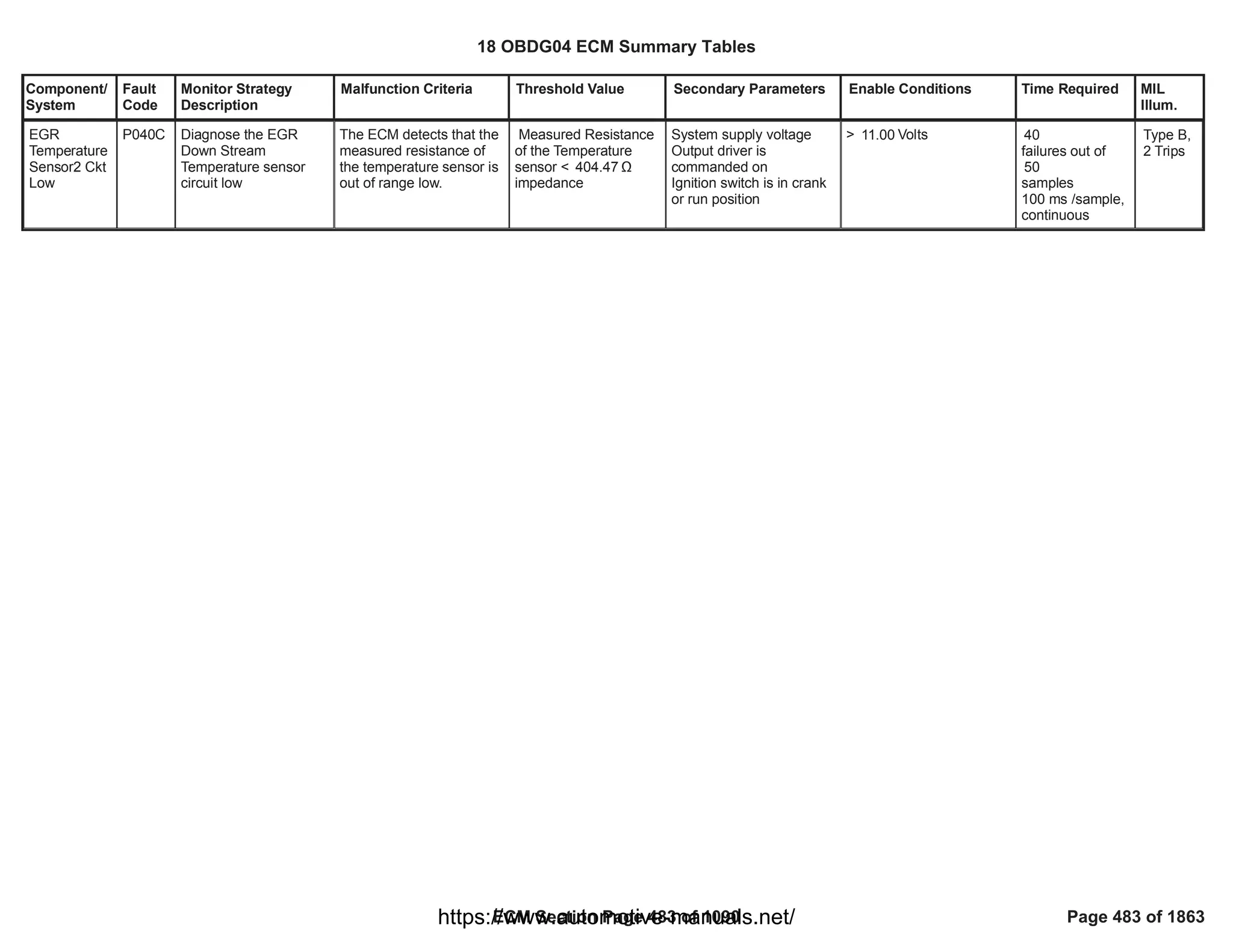


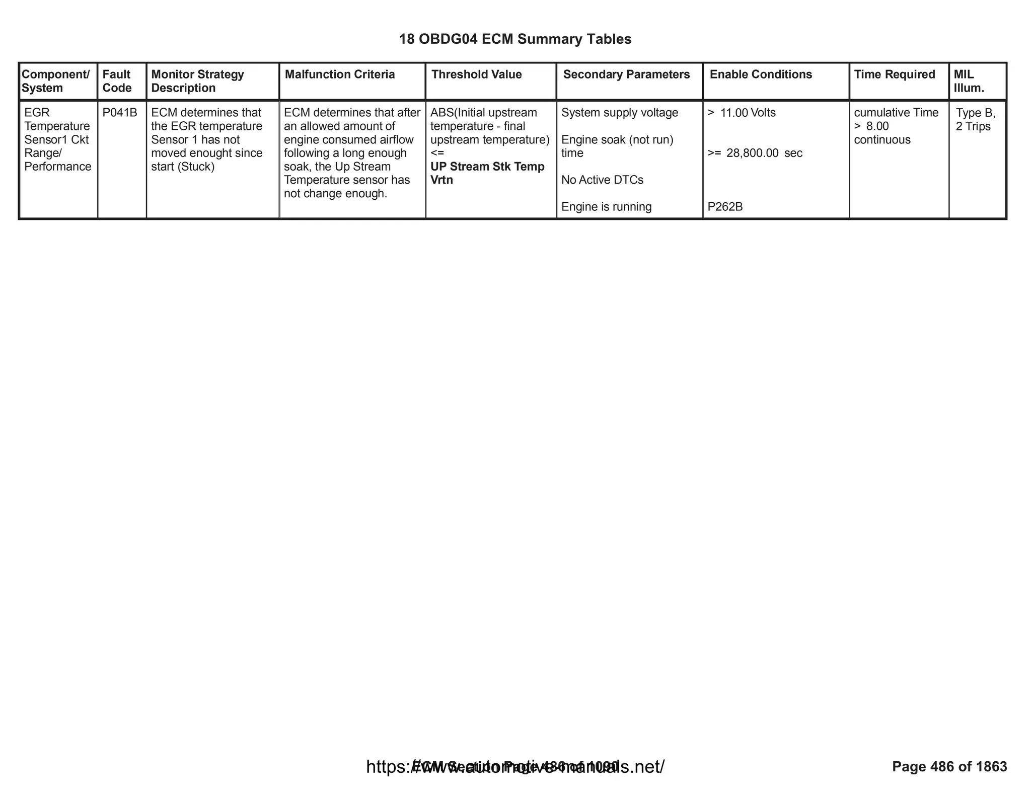
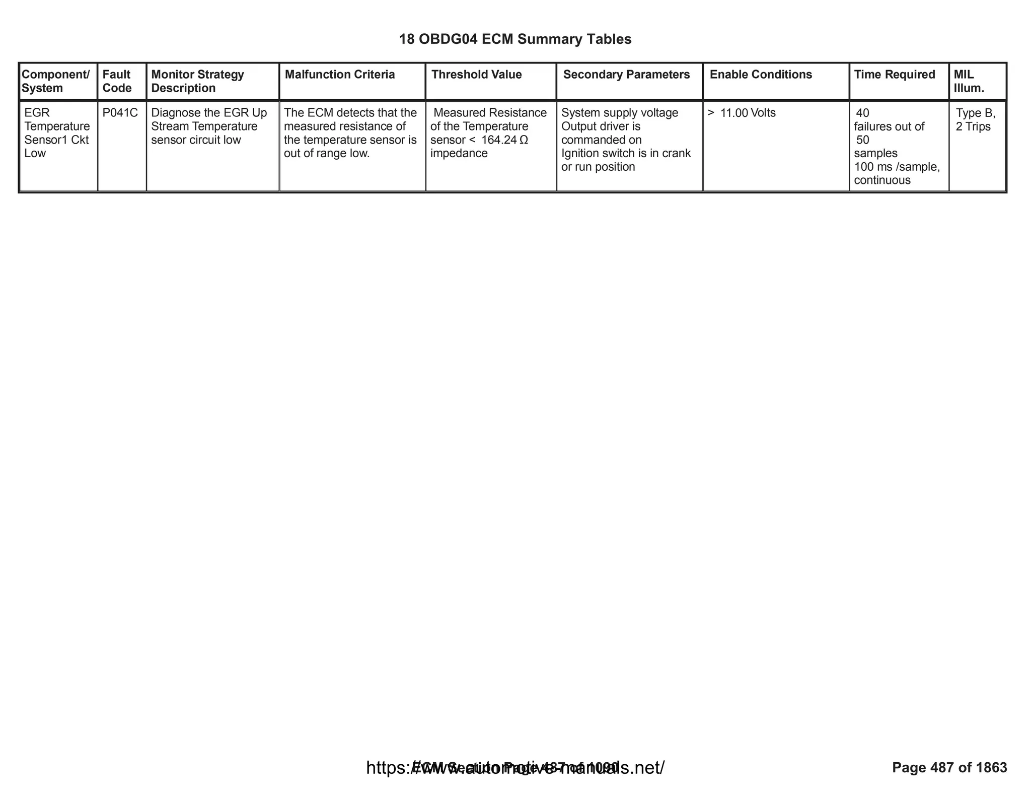

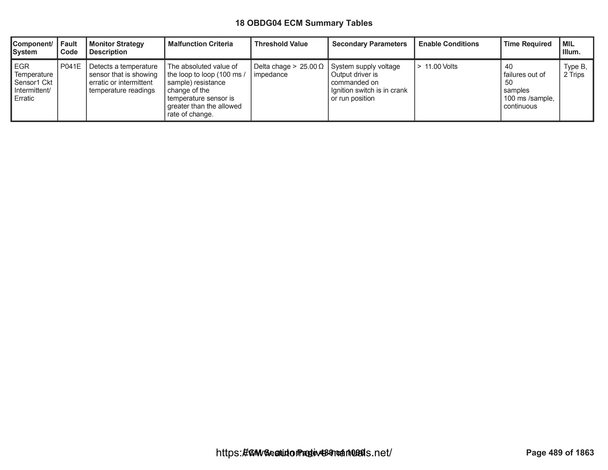
![Component/
System
Fault
Code
Monitor Strategy
Description
Malfunction Criteria Threshold Value Secondary Parameters Enable Conditions Time Required MIL
Illum.
Exhaust Gas
Recirculation
Control
Stuck Open
P042E This monitor detects
the HP EGR valve
mechanically stuck in a
certain position
different from its
defaulted position (fully
closed) when the
actuator is no longer
driven (missing
dafaulted position)
Measured HP EGR
position > maximum
threshold
> [%]
5.00 P0404 is already set
Waiting time after driver
shut off > minimum
threshold (needed for the
spring to drive the valve in
its defaulted position)
Diagnostic system
enabled (no clear code or
EOT in progress)
No faults present on HP
EGR position sensor, HP
EGR valve, HP EGR
position control deviation
> [s]
2.00
==
EGR_PstnShtOffReq
FALSE
No debounce is
present: DTC
sets as soon as
the error is
present
Function task:
6.25 ms
Type A,
1 Trips
18 OBDG04 ECM Summary Tables
ECM Section Page 490 of 1090 Page 490 of 1863
https://www.automotive-manuals.net/](https://image.slidesharecdn.com/gmcenginefaultcodesdtc1-230327071418-56d3c5bb/75/18-OBDG04-ECM-Summary-Tables-490-2048.jpg)
![Component/
System
Fault
Code
Monitor Strategy
Description
Malfunction Criteria Threshold Value Secondary Parameters Enable Conditions Time Required MIL
Illum.
EGR Sensor
"B" Circuit
Range/
Performance
P046E This monitor checks if
the HP EGR cooler
inlet coolant
temperature sensor is
irrational at key on
when compared with
two reference
temperature sensors
after a long soak time.
Difference (absolute
value) between HP EGR
cooler inlet coolant
temperature and a
reference temperature at
power up.
Such difference is
averaged over a calibrate-
able number of samples.
Reference temperature is
calculated as the mean
value between Charge Air
Cooler upstream air
temperature
and Charge Air Cooler
downstream air
temperature.
> [°C]
10.00 Test enabled by
calibration
Diagnostic has not run in
current driving cycle yet
Key on and engine not
running or engine running
for less than a calibratable
time
Runk Crank Relay voltage
in range
The engine has not run
for a minimum time since
last key off
Absolute value of the
difference between
Charge Air Cooler
upstream air temperature
and Charge Air Cooler
downstream air
temperature
No faults detected on
engine off timer
No electrical or self-
correlated faults detected
on HP EGR cooler inlet
coolant temperature
==TRUE
1.00
==TRUE
< [s]
5.00
> [V]
11.00
>= [s]
28,800.00
<= [°C]
10.00
EngineModeNotRunTimer
Error
==FALSE
CEW_TempInCktFA
==FALSE
CEW_TempInSlfCorFA
==FALSE
Test executed
after 1.00
samples are
collected and
their average is
computed.
Function task:
100 ms
Type B,
2 Trips
18 OBDG04 ECM Summary Tables
ECM Section Page 491 of 1090 Page 491 of 1863
https://www.automotive-manuals.net/](https://image.slidesharecdn.com/gmcenginefaultcodesdtc1-230327071418-56d3c5bb/75/18-OBDG04-ECM-Summary-Tables-491-2048.jpg)
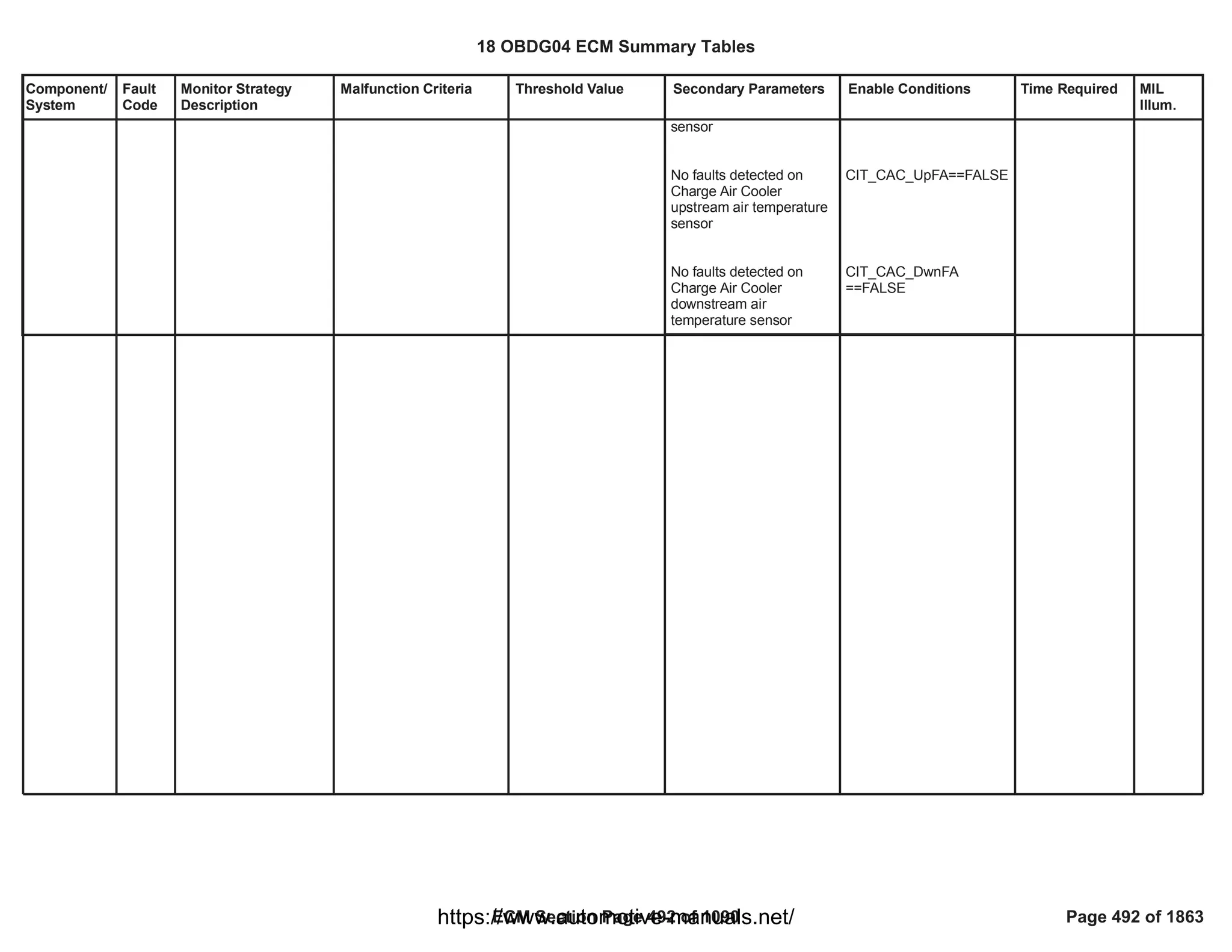
![Component/
System
Fault
Code
Monitor Strategy
Description
Malfunction Criteria Threshold Value Secondary Parameters Enable Conditions Time Required MIL
Illum.
EGR Sensor
"B" Circuit
Intermittent/
Erratic
P046F This monitor checks if
the HP EGR cooler
inlet coolant
temperature sensor
has an intermittent
fault.
HP EGR cooler inlet
coolant temperature value
> T_MAX_threshold [°
C]
OR
< T_MIN_threshold [°
C]
where
- T_MAX_threshold =
(1 - alpha)*T_MAX +
alpha*T_last_good
- T_MIN_threshold = (1
- alpha)*T_MIN +
alpha*T_last_good
- alpha = e^(#fails * ts *
f)
- #fails = number of
consecutive samples
where the test failed
(temperature outside
the range)
- ts = sensor sampling
time
- f = inverse of the
sensor filter response
time ( [Hz])
0.08
- T_MAX = sensor
maximum actual
reading ( [°C])
150.00
- T_MIN = sensor
minimum actual
Test enabled by
calibration
Engine not cranking
Runk Crank Relay voltage
in range
No electrical faults
detected on HP EGR
cooler inlet coolant
temperature sensor
==TRUE
1.00
==TRUE
> [V]
11.00
CEW_TempInCktFA
==FALSE
fail
40.00
counts
out of
sample
50.00
counts
Function task:
100 ms
Type B,
2 Trips
18 OBDG04 ECM Summary Tables
ECM Section Page 493 of 1090 Page 493 of 1863
https://www.automotive-manuals.net/](https://image.slidesharecdn.com/gmcenginefaultcodesdtc1-230327071418-56d3c5bb/75/18-OBDG04-ECM-Summary-Tables-493-2048.jpg)
![Component/
System
Fault
Code
Monitor Strategy
Description
Malfunction Criteria Threshold Value Secondary Parameters Enable Conditions Time Required MIL
Illum.
reading ( [°C])
-60.00
- T_last_good = last
good temperature
(inside the range)
measured by the
sensor
18 OBDG04 ECM Summary Tables
ECM Section Page 494 of 1090 Page 494 of 1863
https://www.automotive-manuals.net/](https://image.slidesharecdn.com/gmcenginefaultcodesdtc1-230327071418-56d3c5bb/75/18-OBDG04-ECM-Summary-Tables-494-2048.jpg)
![Component/
System
Fault
Code
Monitor Strategy
Description
Malfunction Criteria Threshold Value Secondary Parameters Enable Conditions Time Required MIL
Illum.
Exhaust Gas
Recirculation
Position
Exceeded
Learning
Limit
P049D This monitor checks if
the HP EGR position
analog sensor has an
offset with respect to
the nominal position
where the valve does
the learning procedure
(fully closed)
analog position raw
voltage when the valve is
in fully closed position <
low threshold
OR
analog position raw
voltage when the valve is
in fully closed position >
high threshold
< [%5V]
83.50
OR
> [%5V]
93.50
Test enabled by
calibration
Learning procedure at key
off in fully closed position
has been successfully
completed:
- engine coolant
temperature in range;
- no faults present on
engine coolant
temperature sensor;
- valve is in fully closed
position (measured
position smaller than a
threshold);
- difference between max
and min learned values is
smaller than a threshold.
Position control in closed
loop: battery voltage
above a threshold.
No faults present on HP
EGR position sensor, HP
EGR valve, HP EGR
position deviation
End Of Trip event has
elapsed
== 1.00
>= [°C]
60.00
<= [°C]
60.00
==
ECT_Sensor_FA
FALSE
< [%]
100.00
< [%]
100.00
> [V]
5.00
==
EGR_PstnShtOffReq
FALSE
1.00
fail counts out of
1.00
sample counts
Function task:
at key off
Type B,
2 Trips
18 OBDG04 ECM Summary Tables
ECM Section Page 495 of 1090 Page 495 of 1863
https://www.automotive-manuals.net/](https://image.slidesharecdn.com/gmcenginefaultcodesdtc1-230327071418-56d3c5bb/75/18-OBDG04-ECM-Summary-Tables-495-2048.jpg)
![Component/
System
Fault
Code
Monitor Strategy
Description
Malfunction Criteria Threshold Value Secondary Parameters Enable Conditions Time Required MIL
Illum.
Idle Control
System -
Fuel
Quantity
Lower Than
Expected
P054E This DTC detects if the
fuel quantity of the
torque forming pulses
is lower than the
expected fuel quantity
request when the
engine is idle.
Depending on
combustion mode and
gear, different maps of
fuel quantity thresholds
can be used. Each map
depends on engine
speed and engine
coolant temperature
Depending on
Combustion Mode
case
StrongExhGasWarmUp:
{
transmission in Gear:
Fuel quantity of the torque
forming pulses
transmission in Park/
Neutral:
Fuel quantity of the torque
forming pulses
}
case
SoftExhGasWarmUp:
{
transmission in Gear:
Fuel quantity of the torque
forming pulses
< 0.5*
P054E_IFM_MinFuelI
dleV3_G
[mm^3] depending on
engine speed and
engine coolant
temperature
< 0.5*
P054E_IFM_MinFuelI
dleV3_PN
[mm^3] depending on
engine speed and
engine coolant
temperature
< 0.5*
P054E_IFM_MinFuelI
dleV2_G
[mm^3] depending on
engine speed and
engine coolant
For enabling the
monitor, all the
following conditions
must be satisfied
continuously for more
than
Test enabled by
calibration
and
current gear
and
depending on
Gear Selection
Calibration =
CeFULR_e_InGearNeutr
alPark
(
CeFULR_e_InGear:
transmission
CeFULR_e_NeutralPark:
transmission
CeFULR_e_InGearNeutra
lPark:
transmission
)
and
engine speed
and
engine speed
[s]
5.00
[Boolean]
1.00
unchanged
in gear
in park/neutral
in gear and in park neutral
> hysteresis( ,
511.00
+ )[rpm]
511.00 0.00
<hysteresis( ,
1,560.00
+ )[rpm]
1,560.00 0.00
failures
200.00
out of 255.00
samples
1 sample every
cylinder firing
event
Type B,
2 Trips
18 OBDG04 ECM Summary Tables
ECM Section Page 496 of 1090 Page 496 of 1863
https://www.automotive-manuals.net/](https://image.slidesharecdn.com/gmcenginefaultcodesdtc1-230327071418-56d3c5bb/75/18-OBDG04-ECM-Summary-Tables-496-2048.jpg)
![Component/
System
Fault
Code
Monitor Strategy
Description
Malfunction Criteria Threshold Value Secondary Parameters Enable Conditions Time Required MIL
Illum.
transmission in Park/
Neutral:
Fuel quantity of the torque
forming pulses
}
case
HC unloading driving
and park/neutral
(HCS_DeHC_Drive ||
HCS_DeHC_Park):
{
transmission in Gear:
Fuel quantity of the torque
forming pulses
transmission in Park/
Neutral:
Fuel quantity of the torque
forming pulses
}
temperature
< 0.5*
P054E_IFM_MinFuelI
dleV2_PN
[mm^3] depending on
engine speed and
engine coolant
temperature
< 0.5*
P054E_IFM_MinFuelI
dleHC_G
[mm^3] depending on
engine speed and
engine coolant
temperature
< 0.5*
P054E_IFM_MinFuelI
dleHC_PN
[mm^3] depending on
engine speed and
engine coolant
temperature
and
(
OBD Coolant Enable
Criteria
OR
engine coolant
temperature
)
and
outside air temperature
and
vehicle speed
and
enabled in the combustion
mode
and
Accelerator Pedal
Position
and
Engine running
and
PTO_PTO_Active
and
Run Crank voltage
and
No active DTC's:
== TRUE
> hysteresis( ,
-21.00
) [°C]
-20.00
> hysteresis( ,
-21.00
) [°C]
-20.00
< [kph]
3.00
P054E_IFM_CombMode
sEnbl
<= [%]
0.05
-
== 0 [Boolean]
>= [V]
11.00
18 OBDG04 ECM Summary Tables
ECM Section Page 497 of 1090 Page 497 of 1863
https://www.automotive-manuals.net/](https://image.slidesharecdn.com/gmcenginefaultcodesdtc1-230327071418-56d3c5bb/75/18-OBDG04-ECM-Summary-Tables-497-2048.jpg)
![Component/
System
Fault
Code
Monitor Strategy
Description
Malfunction Criteria Threshold Value Secondary Parameters Enable Conditions Time Required MIL
Illum.
default:
{
transmission in Gear:
Fuel quantity of the torque
forming pulses
transmission in Park/
Neutral:
Fuel quantity of the torque
forming pulses
}
< 0.5*
P054E_IFM_MinFuelI
dleC1_G
[mm^3] depending on
engine speed and
engine coolant
temperature
< 0.5*
P054E_IFM_MinFuelI
dleC1_PN
[mm^3] depending on
engine speed and
engine coolant
temperature
Depending on the
OAT Source Calibration
=
CeOATR_e_ECM_OAT_
Sensor
(
CeOATR_e_NonOBD_No
nECM_NonVICM:
default:
)
OAT_OAT_SnsrNonEmiss
FA
OAT_PtEstFiltFA
CrankSensor_TFTKO
ECT_Sensor_FA
Transmission Estimated
Gear Validity
VehicleSpeedSensor_FA
AcceleratorPedalFailure
(FUL_GenericInjSysFA
AND
FUL_GenericInjSysFlt
)
18 OBDG04 ECM Summary Tables
ECM Section Page 498 of 1090 Page 498 of 1863
https://www.automotive-manuals.net/](https://image.slidesharecdn.com/gmcenginefaultcodesdtc1-230327071418-56d3c5bb/75/18-OBDG04-ECM-Summary-Tables-498-2048.jpg)
![Component/
System
Fault
Code
Monitor Strategy
Description
Malfunction Criteria Threshold Value Secondary Parameters Enable Conditions Time Required MIL
Illum.
Idle Control
System -
Fuel
Quantity
Higher Than
Expected
P054F This DTC detects if the
fuel quantity of the
torque forming pulse is
higher than the
expected fuel quantity
request when the
engine is idle.
Depending on
combustion mode and
gear, different maps of
fuel quantity thresholds
can be used. Each map
depends on engine
speed and engine
coolant temperature
Depending on
Combustion Mode
case
StrongExhGasWarmUp:
{
transmission in Gear:
Fuel quantity of the torque
forming pulses
transmission in Park/
Neutral:
Fuel quantity of the torque
forming pulses
}
case
SoftExhGasWarmUp:
{
transmission in Gear:
Fuel quantity of the torque
forming pulses
> 1.5*
P054F_IFM_MaxFuelI
dleV3_G
[mm^3] depending on
engine speed and
engine coolant
temperature
> 1.5*
P054F_IFM_MaxFuelI
dleV3_PN
[mm^3] depending on
engine speed and
engine coolant
temperature
> 1.5*
P054F_IFM_MaxFuelI
dleV2_G
[mm^3] depending on
engine speed and
engine coolant
temperature
For enabling the
monitor, all the
following conditions
must be satisfied
continuously for more
than
Test enabled by
calibration
and
current gear
and
depending on
Gear Selection
Calibration =
CeFULR_e_InGearNeutr
alPark
{
CeFULR_e_InGear:
transmission
CeFULR_e_NeutralPark:
transmission
CeFULR_e_InGearNeutra
lPark:
transmission
}
and
engine speed
and
engine speed
and
[s]
5.00
[Boolean]
1.00
unchanged
in gear
in park/neutral
in gear and in park neutral
> hysteresis( ,
511.00
+ ) [rpm]
511.00 0.00
< hysteresis( ,
1,560.00
+ ) [rpm]
1,560.00 0.00
failures
200.00
out of 255.00
samples
1 sample every
cylinder firing
event
Type B,
2 Trips
18 OBDG04 ECM Summary Tables
ECM Section Page 499 of 1090 Page 499 of 1863
https://www.automotive-manuals.net/](https://image.slidesharecdn.com/gmcenginefaultcodesdtc1-230327071418-56d3c5bb/75/18-OBDG04-ECM-Summary-Tables-499-2048.jpg)
![Component/
System
Fault
Code
Monitor Strategy
Description
Malfunction Criteria Threshold Value Secondary Parameters Enable Conditions Time Required MIL
Illum.
transmission in Park/
Neutral:
Fuel quantity of the torque
forming pulses
}
case
HC unloading driving
and park/neutral
(HCS_DeHC_Drive ||
HCS_DeHC_Park):
{
transmission in Gear:
Fuel quantity of the torque
forming pulses
transmission in Park/
Neutral:
Fuel quantity of the torque
forming pulses
}
default:
> 1.5*
P054F_IFM_MaxFuelI
dleV2_PN
[mm^3] depending on
engine speed and
engine coolant
temperature
> 1.5*
P054F_IFM_MaxFuelI
dleHC_G
[mm^3] depending on
engine speed and
engine coolant
temperature
> 1.5*
P054F_IFM_MaxFuelI
dleHC_PN
[mm^3] depending on
engine speed and
engine coolant
temperature
{
OBD Coolant Enable
Criteria
OR
engine coolant
temperature
}
and
outside air temperature
and
vehicle speed
and
enabled in the combustion
mode
and
Accelerator Pedal
Position
and
Engine running
and
PTO_PTO_Active
and
Run Crank voltage
and
No active DTC's:
Depending on the
OAT Source Calibration
=
CeOATR_e_ECM_OAT_
Sensor
== TRUE
> hysteresis( ,
-21.00
) [°C]
-20.00
> hysteresis( ,
-21.00
) [°C]
-20.00
< [kph]
3.00
P054F_IFM_CombMode
sEnbl
<= [%]
0.05
-
== 0 [Boolean]
>= [V]
11.00
18 OBDG04 ECM Summary Tables
ECM Section Page 500 of 1090 Page 500 of 1863
https://www.automotive-manuals.net/](https://image.slidesharecdn.com/gmcenginefaultcodesdtc1-230327071418-56d3c5bb/75/18-OBDG04-ECM-Summary-Tables-500-2048.jpg)
![Component/
System
Fault
Code
Monitor Strategy
Description
Malfunction Criteria Threshold Value Secondary Parameters Enable Conditions Time Required MIL
Illum.
{
transmission in Gear:
Fuel quantity of the torque
forming pulses
transmission in Park/
Neutral:
Fuel quantity of the torque
forming pulses
}
> 1.5*
P054F_IFM_MaxFuelI
dleC1_G
[mm^3] depending on
engine speed and
engine coolant
temperature
> 1.5*
P054F_IFM_MaxFuelI
dleC1_PN
[mm^3] depending on
engine speed and
engine coolant
temperature
{
CeOATR_e_NonOBD_No
nECM_NonVICM:
default:
}
OAT_OAT_SnsrNonEmiss
FA
OAT_PtEstFiltFA
CrankSensor_TFTKO
ECT_Sensor_FA
Transmission Estimated
Gear Validity
VehicleSpeedSensor_FA
AcceleratorPedalFailure
(FUL_GenericInjSysFA
AND
FUL_GenericInjSysFlt
)
18 OBDG04 ECM Summary Tables
ECM Section Page 501 of 1090 Page 501 of 1863
https://www.automotive-manuals.net/](https://image.slidesharecdn.com/gmcenginefaultcodesdtc1-230327071418-56d3c5bb/75/18-OBDG04-ECM-Summary-Tables-501-2048.jpg)
![Component/
System
Fault
Code
Monitor Strategy
Description
Malfunction Criteria Threshold Value Secondary Parameters Enable Conditions Time Required MIL
Illum.
Internal
Control
Module Fuel
Injector
Control
Performance
P062B This DTC Diagnoses
the internal fuel injector
control module circuit
for circuit faults. The
following check are
performed:
- Chip initialization
- Boost voltage
- chip test
- Code and Parameter
- SPI error (SPI
communication failed)
Driver Status
OR
(
Driver Status
for a number of samples
)
== FAILED (chip test
not passed OR Wrong
download of microcode
OR SPI error)
== NOT INITIALIZED
(chip not initialized OR
Boost Voltage <
)
52.00
> samples
10
Test enabled by
calibration;
and
Battery voltage
and
Key ON
and
Engine is not cranking
and
Boost Voltage has
achieved (at least one
time)
== [Boolean]
1
> [V]
11.00
-
-
[V]
52.00
failures out of
4
samples
8
12.5 ms / sample
Continuous
Type A,
1 Trips
18 OBDG04 ECM Summary Tables
ECM Section Page 502 of 1090 Page 502 of 1863
https://www.automotive-manuals.net/](https://image.slidesharecdn.com/gmcenginefaultcodesdtc1-230327071418-56d3c5bb/75/18-OBDG04-ECM-Summary-Tables-502-2048.jpg)
![Component/
System
Fault
Code
Monitor Strategy
Description
Malfunction Criteria Threshold Value Secondary Parameters Enable Conditions Time Required MIL
Illum.
Fuel Injector
Driver Circuit
Performance
Bank 1
P062D This DTC detects if
there is:
open circuit of the
power supply line of the
injector
or
Boost voltage fault
or
ECU internal fault
The monitoring
determines if the boost
voltage is above a
threshold or below
another threshlod with
hysteresis
Internal ECU Boost
Voltage
> [V]
75.00
OR
< hysteresis( ,
52.00
) [V]
53.00
Test enabled by
calibration;
and
Battery voltage
and
Key ON
and
Engine is not cranking
== [Boolean]
1
> [V]
11.00
-
-
failures out
14
of samples
20
6.25 ms/sample
Continuous
Type A,
1 Trips
18 OBDG04 ECM Summary Tables
ECM Section Page 503 of 1090 Page 503 of 1863
https://www.automotive-manuals.net/](https://image.slidesharecdn.com/gmcenginefaultcodesdtc1-230327071418-56d3c5bb/75/18-OBDG04-ECM-Summary-Tables-503-2048.jpg)
![Component/
System
Fault
Code
Monitor Strategy
Description
Malfunction Criteria Threshold Value Secondary Parameters Enable Conditions Time Required MIL
Illum.
Cylinder 1
Glow Plug
Circuit Low
P066A This DTC checks the
circuit for electrical
integrity during
operation.
Glow plug 1 pin short to
ground.
Test performed by HWIO
A ground short condition
shall be detected if the
circuit attached to the
controller external
connection has an
impedance Rshortdet to a
voltage source within the
Vehicle Ground Voltage
Range relative to
PWRGND.
A ground short condition
shall not be detected
if the circuit impedance is
higher than Rload_min.
A ground short condition
will be set in case of
Inrush overcurrent
detection. It is intended to
detect if the Inrush current
profile is beyond the
specified value (see
Inrush_current_profile
Table). This detection is
only done at key on (once
per driving cycle).
Rshortdet = 0.11 [Ohm]
Rload_min = 0.19
[Ohm]
Test enabled by
calibration;
Key on and engine
running (cranking
excluded);
Battery voltage in range;
No faults detected on
glow plug system supply;
Duty cycle above a
calibratable threshold;
Diagnostic system is not
disabled;
[boolean]
1.00
VePMDR_b_RunCrankAc
tive = TRUE;
VeEMDR_b_EngModeCra
nk = FALSE;
VeLVTR_b_RunCrankIgnI
nRange = TRUE;
GLO_GlowPlugSplyVoltC
ktTFTKO
[%]
2.00
VeDRER_DiagSystemDs
bl = FALSE;
fail
20.00
samples
over
samples
40.00
Time task: 100
[ms]
Type B,
2 Trips
+ glow
lamp ON
18 OBDG04 ECM Summary Tables
ECM Section Page 504 of 1090 Page 504 of 1863
https://www.automotive-manuals.net/](https://image.slidesharecdn.com/gmcenginefaultcodesdtc1-230327071418-56d3c5bb/75/18-OBDG04-ECM-Summary-Tables-504-2048.jpg)
![Component/
System
Fault
Code
Monitor Strategy
Description
Malfunction Criteria Threshold Value Secondary Parameters Enable Conditions Time Required MIL
Illum.
Cylinder 1
Glow Plug
Circuit High
P066B This DTC checks the
circuit for electrical
integrity during
operation.
Glow plug 1 pin short to
high voltage.
Test performed by HWIO
• If the Load resistance is
higher than 0.65 Ohm a
power short condition
shall be detected if the
circuit attached to the
Controller external
connection has an
impedance below R1 to a
voltage source
within the Normal
Operating Voltage Range
or the High Operating
Voltage Range.
• If the Load resistance is
between 0.2 Ohm to 0.65
Ohm a power short
condition shall be
detected if the circuit
attached to the Controller
external connection has
an impedance below R2
to a voltage source
within the Normal
Operating Voltage Range
or the High Operating
Voltage Range.
R1 = 0.5 [Ohm]
R2 = 0.14 [Ohm]
Test enabled by
calibration;
Key on and engine
running (cranking
excluded);
Battery voltage in range;
No faults detected on
glow plug system supply;
Diagnostic system is not
disabled;
[boolean]
1.00
VePMDR_b_RunCrankAc
tive = TRUE;
VeEMDR_b_EngModeCra
nk = FALSE;
VeLVTR_b_RunCrankIgnI
nRange = TRUE;
GLO_GlowPlugSplyVoltC
ktTFTKO
VeDRER_DiagSystemDs
bl = FALSE;
fail
20.00
samples
over
samples
40.00
Time task: 100
[ms]
Type B,
2 Trips
+ glow
lamp ON
18 OBDG04 ECM Summary Tables
ECM Section Page 505 of 1090 Page 505 of 1863
https://www.automotive-manuals.net/](https://image.slidesharecdn.com/gmcenginefaultcodesdtc1-230327071418-56d3c5bb/75/18-OBDG04-ECM-Summary-Tables-505-2048.jpg)
![Component/
System
Fault
Code
Monitor Strategy
Description
Malfunction Criteria Threshold Value Secondary Parameters Enable Conditions Time Required MIL
Illum.
Cylinder 2
Glow Plug
Circuit Low
P066C This DTC checks the
circuit for electrical
integrity during
operation.
Glow plug 2 pin short to
ground.
Test performed by HWIO
A ground short condition
shall be detected if the
circuit attached to the
controller external
connection has an
impedance Rshortdet to a
voltage source within the
Vehicle Ground Voltage
Range relative to
PWRGND.
A ground short condition
shall not be detected
if the circuit impedance is
higher than Rload_min.
A ground short condition
will be set in case of
Inrush overcurrent
detection. It is intended to
detect if the Inrush current
profile is beyond the
specified value (see
Inrush_current_profile
Table). This detection is
only done at key on (once
per driving cycle).
Rshortdet = 0.11 [Ohm]
Rload_min = 0.19
[Ohm]
Test enabled by
calibration;
Key on and engine
running (cranking
excluded);
Battery voltage in range;
No faults detected on
glow plug system supply;
Duty cycle above a
calibratable threshold;
Diagnostic system is not
disable;
[boolean]
1.00
VePMDR_b_RunCrankAc
tive = TRUE;
VeEMDR_b_EngModeCra
nk = FALSE;
VeLVTR_b_RunCrankIgnI
nRange = TRUE;
GLO_GlowPlugSplyVoltC
ktTFTKO
[%]
2.00
VeDRER_DiagSystemDs
bl = FALSE;
fail
20.00
samples
over
samples
40.00
Time task: 100
[ms]
Type B,
2 Trips
+ glow
lamp ON
18 OBDG04 ECM Summary Tables
ECM Section Page 506 of 1090 Page 506 of 1863
https://www.automotive-manuals.net/](https://image.slidesharecdn.com/gmcenginefaultcodesdtc1-230327071418-56d3c5bb/75/18-OBDG04-ECM-Summary-Tables-506-2048.jpg)
![Component/
System
Fault
Code
Monitor Strategy
Description
Malfunction Criteria Threshold Value Secondary Parameters Enable Conditions Time Required MIL
Illum.
Cylinder 2
Glow Plug
Circuit High
P066D This DTC checks the
circuit for electrical
integrity during
operation.
Glow plug 2 pin short to
high voltage.
Test performed by HWIO
• If the Load resistance is
higher than 0.65 Ohma
power short condition
shall be detected if the
circuit attached to the
Controller external
connection has an
impedance below R1 to a
voltage source
within the Normal
Operating Voltage Range
or the High Operating
Voltage Range.
• If the Load resistance is
between 0.2 Ohm to 0.65
Ohma power short
condition shall be
detected if the circuit
attached to the Controller
external connection has
an impedance below R2
to a voltage source
within the Normal
Operating Voltage Range
or the High Operating
Voltage Range.
R1 = 0.5 [Ohm]
R2= 0.14 [Ohm]
Test enabled by
calibration;
Key on and engine
running (cranking
excluded);
Battery voltage in range;
No faults detected on
glow plug system supply;
Diagnostic system is not
disabled;
[boolean]
1.00
VePMDR_b_RunCrankAc
tive = TRUE;
VeEMDR_b_EngModeCra
nk = FALSE;
VeLVTR_b_RunCrankIgnI
nRange = TRUE;
GLO_GlowPlugSplyVoltC
ktTFTKO
VeDRER_DiagSystemDs
bl = FALSE;
fail
20.00
samples
over
samples
40.00
Time task: 100
[ms]
Type B,
2 Trips
+ glow
lamp ON
18 OBDG04 ECM Summary Tables
ECM Section Page 507 of 1090 Page 507 of 1863
https://www.automotive-manuals.net/](https://image.slidesharecdn.com/gmcenginefaultcodesdtc1-230327071418-56d3c5bb/75/18-OBDG04-ECM-Summary-Tables-507-2048.jpg)
![Component/
System
Fault
Code
Monitor Strategy
Description
Malfunction Criteria Threshold Value Secondary Parameters Enable Conditions Time Required MIL
Illum.
Cylinder 3
Glow Plug
Circuit Low
P066E This DTC checks the
circuit for electrical
integrity during
operation.
Glow plug 3 pin short to
ground.
Test performed by HWIO
A ground short condition
shall be detected if the
circuit attached to the
controller external
connection has an
impedance Rshortdet to a
voltage source within the
Vehicle Ground Voltage
Range relative to
PWRGND.
A ground short condition
shall not be detected
if the circuit impedance is
higher than Rload_min.
A ground short condition
will be set in case of
Inrush overcurrent
detection. It is intended to
detect if the Inrush current
profile is beyond the
specified value (see
Inrush_current_profile
Table). This detection is
only done at key on (once
per driving cycle).
Rshortdet = 0.11 [Ohm]
Rload_min = 0.19
[Ohm]
Test enabled by
calibration;
Key on and engine
running (cranking
excluded);
Battery voltage in range;
No faults detected on
glow plug system supply;
Duty cycle above a
calibratable threshold;
Diagnostic system is not
disable;
[boolean]
1.00
VePMDR_b_RunCrankAc
tive = TRUE;
VeEMDR_b_EngModeCra
nk = FALSE;
VeLVTR_b_RunCrankIgnI
nRange = TRUE;
GLO_GlowPlugSplyVoltC
ktTFTKO
[%]
2.00
VeDRER_DiagSystemDs
bl = FALSE;
fail
20.00
samples
over
samples
40.00
Time task: 100
[ms]
Type B,
2 Trips
+ glow
lamp ON
18 OBDG04 ECM Summary Tables
ECM Section Page 508 of 1090 Page 508 of 1863
https://www.automotive-manuals.net/](https://image.slidesharecdn.com/gmcenginefaultcodesdtc1-230327071418-56d3c5bb/75/18-OBDG04-ECM-Summary-Tables-508-2048.jpg)
![Component/
System
Fault
Code
Monitor Strategy
Description
Malfunction Criteria Threshold Value Secondary Parameters Enable Conditions Time Required MIL
Illum.
Cylinder 3
Glow Plug
Circuit High
P066F This DTC checks the
circuit for electrical
integrity during
operation.
Glow plug 3 pin short to
high voltage.
Test performed by HWIO
• If the Load resistance is
higher than 0.65 Ohma
power short condition
shall be detected if the
circuit attached to the
Controller external
connection has an
impedance below R1 to a
voltage source
within the Normal
Operating Voltage Range
or the High Operating
Voltage Range.
• If the Load resistance is
between 0.2 Ohm to 0.65
Ohma power short
condition shall be
detected if the circuit
attached to the Controller
external connection has
an impedance below R2
to a voltage source
within the Normal
Operating Voltage Range
or the High Operating
Voltage Range.
R1 = 0.5 [Ohm]
R2= 0.14 [Ohm]
Test enabled by
calibration;
Key on and engine
running (cranking
excluded);
Battery voltage in range;
No faults detected on
glow plug system supply;
Diagnostic system is not
disabled;
[boolean]
1.00
VePMDR_b_RunCrankAc
tive = TRUE;
VeEMDR_b_EngModeCra
nk = FALSE;
VeLVTR_b_RunCrankIgnI
nRange = TRUE;
GLO_GlowPlugSplyVoltC
ktTFTKO
VeDRER_DiagSystemDs
bl = FALSE;
fail
20.00
samples
over
samples
40.00
Time task: 100
[ms]
Type B,
2 Trips
+ glow
lamp ON
18 OBDG04 ECM Summary Tables
ECM Section Page 509 of 1090 Page 509 of 1863
https://www.automotive-manuals.net/](https://image.slidesharecdn.com/gmcenginefaultcodesdtc1-230327071418-56d3c5bb/75/18-OBDG04-ECM-Summary-Tables-509-2048.jpg)
![Component/
System
Fault
Code
Monitor Strategy
Description
Malfunction Criteria Threshold Value Secondary Parameters Enable Conditions Time Required MIL
Illum.
Cylinder 1
Glow Plug
Circuit/Open
P0671 This DTC checks the
circuit for electrical
integrity during
operation.
Glow plug 1 pin open
load.
Test performed by HWIO.
An open circuit condition
shall be detected if the
circuit attached to the
Controller external
connection has an
impedance R and shall
not be detected if the
circuit impedance is less
than the Ropmin
R = 200 [kOhm]
Ropmin = 16 [Ohm]
Test enabled by
calibration;
Key on and engine
running (cranking
excluded);
Battery voltage in range;
No faults detected on
glow plug system supply;
Duty cycle above a
calibratable threshold;
Diagnostic system is not
disabled;
[boolean]
1.00
VePMDR_b_RunCrankAc
tive = TRUE;
VeEMDR_b_EngModeCra
nk = FALSE;
VeLVTR_b_RunCrankIgnI
nRange = TRUE;
GLO_GlowPlugSplyVoltC
ktTFTKO
[%]
2.00
VeDRER_DiagSystemDs
bl = FALSE;
fail
20.00
samples
over
samples
40.00
Time task: 100
[ms]
Type B,
2 Trips
+ glow
lamp ON
18 OBDG04 ECM Summary Tables
ECM Section Page 510 of 1090 Page 510 of 1863
https://www.automotive-manuals.net/](https://image.slidesharecdn.com/gmcenginefaultcodesdtc1-230327071418-56d3c5bb/75/18-OBDG04-ECM-Summary-Tables-510-2048.jpg)
![Component/
System
Fault
Code
Monitor Strategy
Description
Malfunction Criteria Threshold Value Secondary Parameters Enable Conditions Time Required MIL
Illum.
Cylinder 2
Glow Plug
Circuit/Open
P0672 This DTC checks the
circuit for electrical
integrity during
operation.
Glow plug 2 pin open
load.
Test performed by HWIO.
An open circuit condition
shall be detected if the
circuit attached to the
Controller external
connection has an
impedance R and shall
not be detected if the
circuit impedance is less
than the Ropmin
R = 200 [kOhm]
Ropmin = 16 [Ohm]
Test enabled by
calibration;
Key on and engine
running (cranking
excluded);
Battery voltage in range;
No faults detected on
glow plug system supply;
Duty cycle above a
calibratable threshold;
Diagnostic system is not
disabled;
[boolean]
1.00
VePMDR_b_RunCrankAc
tive = TRUE;
VeEMDR_b_EngModeCra
nk = FALSE;
VeLVTR_b_RunCrankIgnI
nRange = TRUE;
GLO_GlowPlugSplyVoltC
ktTFTKO
[%]
2.00
VeDRER_DiagSystemDs
bl = FALSE;
fail
20.00
samples
over
samples
40.00
Time task: 100
[ms]
Type B,
2 Trips
+ glow
lamp ON
18 OBDG04 ECM Summary Tables
ECM Section Page 511 of 1090 Page 511 of 1863
https://www.automotive-manuals.net/](https://image.slidesharecdn.com/gmcenginefaultcodesdtc1-230327071418-56d3c5bb/75/18-OBDG04-ECM-Summary-Tables-511-2048.jpg)
![Component/
System
Fault
Code
Monitor Strategy
Description
Malfunction Criteria Threshold Value Secondary Parameters Enable Conditions Time Required MIL
Illum.
Cylinder 3
Glow Plug
Circuit/Open
P0673 This DTC checks the
circuit for electrical
integrity during
operation.
Glow plug 3 pin open
load.
Test performed by HWIO.
An open circuit condition
shall be detected if the
circuit attached to the
Controller external
connection has an
impedance R and shall
not be detected if the
circuit impedance is less
than the Ropmin
R = 200 [kOhm]
Ropmin = 16 [Ohm]
Test enabled by
calibration;
Key on and engine
running (cranking
excluded);
Battery voltage in range;
No faults detected on
glow plug system supply;
Duty cycle above a
calibratable threshold;
Diagnostic system is not
disabled;
[boolean]
1.00
VePMDR_b_RunCrankAc
tive = TRUE;
VeEMDR_b_EngModeCra
nk = FALSE;
VeLVTR_b_RunCrankIgnI
nRange = TRUE;
GLO_GlowPlugSplyVoltC
ktTFTKO
[%]
2.00
VeDRER_DiagSystemDs
bl = FALSE;
fail
20.00
samples
over
samples
40.00
Time task: 100
[ms]
Type B,
2 Trips
+ glow
lamp ON
18 OBDG04 ECM Summary Tables
ECM Section Page 512 of 1090 Page 512 of 1863
https://www.automotive-manuals.net/](https://image.slidesharecdn.com/gmcenginefaultcodesdtc1-230327071418-56d3c5bb/75/18-OBDG04-ECM-Summary-Tables-512-2048.jpg)
![Component/
System
Fault
Code
Monitor Strategy
Description
Malfunction Criteria Threshold Value Secondary Parameters Enable Conditions Time Required MIL
Illum.
Cylinder 4
Glow Plug
Circuit/Open
P0674 This DTC checks the
circuit for electrical
integrity during
operation.
Glow plug 4 pin open
load.
Test performed by HWIO.
An open circuit condition
shall be detected if the
circuit attached to the
Controller external
connection has an
impedance R and shall
not be detected if the
circuit impedance is less
than the Ropmin
R = 200 [kOhm]
Ropmin = 16 [Ohm]
Test enabled by
calibration;
Key on and engine
running (cranking
excluded);
Battery voltage in range;
No faults detected on
glow plug system supply;
Duty cycle above a
calibratable threshold;
Diagnostic system is not
disabled;
[boolean]
1.00
VePMDR_b_RunCrankAc
tive = TRUE;
VeEMDR_b_EngModeCra
nk = FALSE;
VeLVTR_b_RunCrankIgnI
nRange = TRUE;
GLO_GlowPlugSplyVoltC
ktTFTKO
[%]
2.00
VeDRER_DiagSystemDs
bl = FALSE;
fail
20.00
samples
over
samples
40.00
Time task: 100
[ms]
Type B,
2 Trips
+ glow
lamp ON
18 OBDG04 ECM Summary Tables
ECM Section Page 513 of 1090 Page 513 of 1863
https://www.automotive-manuals.net/](https://image.slidesharecdn.com/gmcenginefaultcodesdtc1-230327071418-56d3c5bb/75/18-OBDG04-ECM-Summary-Tables-513-2048.jpg)
![Component/
System
Fault
Code
Monitor Strategy
Description
Malfunction Criteria Threshold Value Secondary Parameters Enable Conditions Time Required MIL
Illum.
Cylinder 4
Glow Plug
Circuit Low
P067A This DTC checks the
circuit for electrical
integrity during
operation.
Glow plug 4 pin short to
ground.
Test performed by HWIO
A ground short condition
shall be detected if the
circuit attached to the
controller external
connection has an
impedance Rshortdet to a
voltage source within the
Vehicle Ground Voltage
Range relative to
PWRGND.
A ground short condition
shall not be detected
if the circuit impedance is
higher than Rload_min.
A ground short condition
will be set in case of
Inrush overcurrent
detection. It is intended to
detect if the Inrush current
profile is beyond the
specified value (see
Inrush_current_profile
Table). This detection is
only done at key on (once
per driving cycle).
Rshortdet = 0.11 [Ohm]
Rload_min = 0.19
[Ohm]
Test enabled by
calibration;
Key on and engine
running (cranking
excluded);
Battery voltage in range;
No faults detected on
glow plug system supply;
Duty cycle above a
calibratable threshold;
Diagnostic system is not
disable;
[boolean]
1.00
VePMDR_b_RunCrankAc
tive = TRUE;
VeEMDR_b_EngModeCra
nk = FALSE;
VeLVTR_b_RunCrankIgnI
nRange = TRUE;
GLO_GlowPlugSplyVoltC
ktTFTKO
[%]
2.00
VeDRER_DiagSystemDs
bl = FALSE;
fail
20.00
samples
over
samples
40.00
Time task: 100
[ms]
Type B,
2 Trips
+ glow
lamp ON
18 OBDG04 ECM Summary Tables
ECM Section Page 514 of 1090 Page 514 of 1863
https://www.automotive-manuals.net/](https://image.slidesharecdn.com/gmcenginefaultcodesdtc1-230327071418-56d3c5bb/75/18-OBDG04-ECM-Summary-Tables-514-2048.jpg)
![Component/
System
Fault
Code
Monitor Strategy
Description
Malfunction Criteria Threshold Value Secondary Parameters Enable Conditions Time Required MIL
Illum.
Cylinder 4
Glow Plug
Circuit High
P067B This DTC checks the
circuit for electrical
integrity during
operation.
Glow plug 4 pin short to
high voltage.
Test performed by HWIO
• If the Load resistance is
higher than 0.65 Ohma
power short condition
shall be detected if the
circuit attached to the
Controller external
connection has an
impedance below R1 to a
voltage source
within the Normal
Operating Voltage Range
or the High Operating
Voltage Range.
• If the Load resistance is
between 0.2 Ohm to 0.65
Ohma power short
condition shall be
detected if the circuit
attached to the Controller
external connection has
an impedance below R2
to a voltage source
within the Normal
Operating Voltage Range
or the High Operating
Voltage Range.
R1 = 0.5 [Ohm]
R2= 0.14 [Ohm]
Test enabled by
calibration;
Key on and engine
running (cranking
excluded);
Battery voltage in range;
No faults detected on
glow plug system supply;
Diagnostic system is not
disabled;
[boolean]
1.00
VePMDR_b_RunCrankAc
tive = TRUE;
VeEMDR_b_EngModeCra
nk = FALSE;
VeLVTR_b_RunCrankIgnI
nRange = TRUE;
GLO_GlowPlugSplyVoltC
ktTFTKO
VeDRER_b_DiagSystem
Dsbl = FALSE;
fail
20.00
samples
over
samples
40.00
Time task: 100
[ms]
Type B,
2 Trips
+ glow
lamp ON
18 OBDG04 ECM Summary Tables
ECM Section Page 515 of 1090 Page 515 of 1863
https://www.automotive-manuals.net/](https://image.slidesharecdn.com/gmcenginefaultcodesdtc1-230327071418-56d3c5bb/75/18-OBDG04-ECM-Summary-Tables-515-2048.jpg)
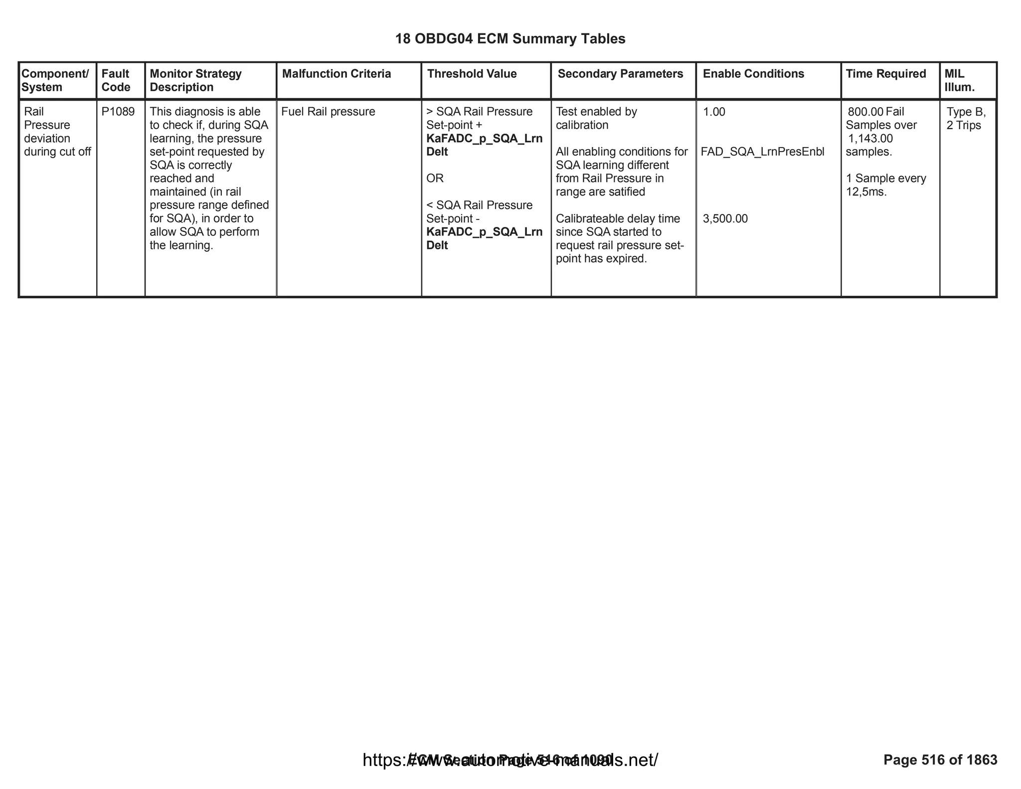
![Component/
System
Fault
Code
Monitor Strategy
Description
Malfunction Criteria Threshold Value Secondary Parameters Enable Conditions Time Required MIL
Illum.
Charge Air
Cooler
Temperature
Sensor
Down Circuit
Performance
P10D5 This monitor checks if
the CAC down air
temperature sensor is
irrational at key on
when compared with
two reference
temperature sensors
after a long soak time
Charge air cooler down
air temperature is
compared at power up
with an average
temperature calculated
using the intake manifold
air temperature sensor
and the fuel temperature
sensor over a calibratable
number of samples
> [°C]
20.00 Enablement calibration
set to TRUE
Key on and engine not
running or engine running
for less than a calibratable
time
Runk Crank Relay voltage
in range
The engine has not run
for a calibratable time
since last key off
No faults detected on
engine off timer
Absolute value of the
difference between intake
manifold air temperature
and fuel temperature
smaller than a calibratable
threshold
No electrical or self-
correlated faults detected
on charge air cooler down
air temperature sensors
No faults detected on
intake manifold air
== 1.00
>= [s]
0.10
> [V]
11.00
>= [s]
28,800.00
EngineModeNotRunTimer
Error
==FALSE
< [°C]
45.00
CIT_CAC_DwnCktFA
==FALSE
OR
CIT_CAC_DwnSelfCorFA
==FALSE
MnfdTempSensorFA
==FALSE
Test executed
after a counter of
samples
1.00
Functional task:
100 ms
Type B,
2 Trips
18 OBDG04 ECM Summary Tables
ECM Section Page 517 of 1090 Page 517 of 1863
https://www.automotive-manuals.net/](https://image.slidesharecdn.com/gmcenginefaultcodesdtc1-230327071418-56d3c5bb/75/18-OBDG04-ECM-Summary-Tables-517-2048.jpg)

![Component/
System
Fault
Code
Monitor Strategy
Description
Malfunction Criteria Threshold Value Secondary Parameters Enable Conditions Time Required MIL
Illum.
Charge Air
Cooler
Temperature
Sensor
Down Circuit
Low
P10D6 This monitor checks if
the CAC down air
temperature sensor is
out of electrical range
low
Charge air cooler down
air temperature resistance
value < low threshold
< [ohm]
55.00 Test enabled by
calibration
Engine not cranking
Runk Crank Relay voltage
in range
== 1.00
> [V]
11.00
fail
50.00
counter over
sample
63.00
counter
Functional task:
100 ms
Type B,
2 Trips
18 OBDG04 ECM Summary Tables
ECM Section Page 519 of 1090 Page 519 of 1863
https://www.automotive-manuals.net/](https://image.slidesharecdn.com/gmcenginefaultcodesdtc1-230327071418-56d3c5bb/75/18-OBDG04-ECM-Summary-Tables-519-2048.jpg)
![Component/
System
Fault
Code
Monitor Strategy
Description
Malfunction Criteria Threshold Value Secondary Parameters Enable Conditions Time Required MIL
Illum.
Charge Air
Cooler
Temperature
Sensor
Down Circuit
High
P10D7 This monitor checks if
the CAC down air
temperature sensoris
out of electrical range
high
Charge air cooler down
air temperature resistance
value > high threshold
> [ohm]
100,605.00 Test enabled by
calibration
Engine not cranking
Runk Crank Relay voltage
in range
== 1.00
> [V]
11.00
fail
50.00
counter over
sample
63.00
counter
Functional task:
100 ms
Type B,
2 Trips
18 OBDG04 ECM Summary Tables
ECM Section Page 520 of 1090 Page 520 of 1863
https://www.automotive-manuals.net/](https://image.slidesharecdn.com/gmcenginefaultcodesdtc1-230327071418-56d3c5bb/75/18-OBDG04-ECM-Summary-Tables-520-2048.jpg)
![Component/
System
Fault
Code
Monitor Strategy
Description
Malfunction Criteria Threshold Value Secondary Parameters Enable Conditions Time Required MIL
Illum.
Charge Air
Cooler
Temperature
Sensor
Down Circuit
Intermittent/
Erratic
P10D8 This monitor checks if
the CAC down air
temperature has an
intermittent fault
Charge air cooler down
air temperature value >
T_MAX_threshold
Charge air cooler down
air temperature value <
T_MIN_threshold
where
- T_MAX_threshold = (1 -
alpha)*T_MAX +
alpha*T_last_good
- T_MIN_threshold = (1 -
alpha)*T_MIN +
alpha*T_last_good
- alpha = e^(#fails + 1)*(ts/
tau)
- #fails = number of
consecutive samples
where the test failed
- ts = sensor sampling
time
- tau = sensor filter
response time
- T_MAX = sensor
maximum actual reading
- T_MIN = sensor
minimum actual reading
- T_last_good = last good
temperature measured by
the sensor
> [°C]
300.00
< [°C]
-60.00
Test enabled by
calibration
Engine not cranking
Runk Crank Relay voltage
in range
No electrical faults
detected on CAC down air
temperature sensor
== 1.00
> [V]
11.00
CIT_CAC_DwnCktFA
==FALSE
50.00
fail counter over
sample
63.00
counter
Functional task:
100 ms
Type B,
2 Trips
18 OBDG04 ECM Summary Tables
ECM Section Page 521 of 1090 Page 521 of 1863
https://www.automotive-manuals.net/](https://image.slidesharecdn.com/gmcenginefaultcodesdtc1-230327071418-56d3c5bb/75/18-OBDG04-ECM-Summary-Tables-521-2048.jpg)
![Component/
System
Fault
Code
Monitor Strategy
Description
Malfunction Criteria Threshold Value Secondary Parameters Enable Conditions Time Required MIL
Illum.
Injector 1
Positive
Voltage
Control
Circuit
Shorted to
Control
Circuit (For 4
Cylinder
Engines)
P1248 This DTC detects a
shorted load on Injector
1
Voltage high across low
side and High side drivers
during on state indicates
low side shorted to high
side
the time to reach the 2
A threshold of the
injector current is
shorter than 2 us
Test enabled by
calibration;
and
Battery voltage
and
Key ON
and
Engine is not cranking
and
Engine Running
and
FUL_OutEnblCyl_CiEPS
R_CylinderA
and
At least one injection
pulse is requested by the
application software
(
FUL_FuelInjectedCyl_CiE
PSR_CylinderA
== [Boolean]
1
> [V]
11.00
-
-
>= [s]
1.00
== 0 [Boolean]
== TRUE);
failures out of
5
samples
10
100 ms/sample
Continuous
Type A,
1 Trips
18 OBDG04 ECM Summary Tables
ECM Section Page 522 of 1090 Page 522 of 1863
https://www.automotive-manuals.net/](https://image.slidesharecdn.com/gmcenginefaultcodesdtc1-230327071418-56d3c5bb/75/18-OBDG04-ECM-Summary-Tables-522-2048.jpg)
![Component/
System
Fault
Code
Monitor Strategy
Description
Malfunction Criteria Threshold Value Secondary Parameters Enable Conditions Time Required MIL
Illum.
Injector 2
Positive
Voltage
Control
Circuit
Shorted to
Control
Circuit (For 4
Cylinder
Engines)
P1249 This DTC detects a
shorted load on Injector
2
Voltage high across low
side and High side drivers
during on state indicates
low side shorted to high
side
the time to reach the 2
A threshold of the
injector current is
shorter than 2 us
Test enabled by
calibration;
and
Battery voltage
and
Key ON
and
Engine is not cranking
and
Engine Running
and
FUL_OutEnblCyl_CiEPS
R_CylinderD
and
At least one injection
pulse is requested by the
application software
(
FUL_FuelInjectedCyl_CiE
PSR_CylinderD
== [Boolean]
1
> [V]
11.00
-
-
>= [s]
1.00
== 0 [Boolean]
== TRUE);
failures out of
5
samples
10
100 ms/sample
Continuous
Type A,
1 Trips
18 OBDG04 ECM Summary Tables
ECM Section Page 523 of 1090 Page 523 of 1863
https://www.automotive-manuals.net/](https://image.slidesharecdn.com/gmcenginefaultcodesdtc1-230327071418-56d3c5bb/75/18-OBDG04-ECM-Summary-Tables-523-2048.jpg)
![Component/
System
Fault
Code
Monitor Strategy
Description
Malfunction Criteria Threshold Value Secondary Parameters Enable Conditions Time Required MIL
Illum.
Injector 3
Positive
Voltage
Control
Circuit
Shorted to
Control
Circuit (For 4
Cylinder
Engines)
P124A This DTC detects a
shorted load on Injector
3
Voltage high across low
side and High side drivers
during on state indicates
low side shorted to high
side
the time to reach the 2
A threshold of the
injector current is
shorter than 2 us
Test enabled by
calibration;
and
Battery voltage
and
Key ON
and
Engine is not cranking
and
Engine Running
and
FUL_OutEnblCyl_CiEPS
R_CylinderB
and
At least one injection
pulse is requested by the
application software
(
FUL_FuelInjectedCyl_CiE
PSR_CylinderB
== [Boolean]
1
> [V]
11.00
-
-
>= [s]
1.00
== 0 [Boolean]
== TRUE);
failures out of
5
samples
10
100 ms/sample
Continuous
Type A,
1 Trips
18 OBDG04 ECM Summary Tables
ECM Section Page 524 of 1090 Page 524 of 1863
https://www.automotive-manuals.net/](https://image.slidesharecdn.com/gmcenginefaultcodesdtc1-230327071418-56d3c5bb/75/18-OBDG04-ECM-Summary-Tables-524-2048.jpg)
![Component/
System
Fault
Code
Monitor Strategy
Description
Malfunction Criteria Threshold Value Secondary Parameters Enable Conditions Time Required MIL
Illum.
Injector 4
Positive
Voltage
Control
Circuit
Shorted to
Control
Circuit (For 4
Cylinder
Engines)
P124B This DTC detects a
shorted load on Injector
4
Voltage high across low
side and High side drivers
during on state indicates
low side shorted to high
side
the time to reach the 2
A threshold of the
injector current is
shorter than 2 us
Test enabled by
calibration;
and
Battery voltage
and
Key ON
and
Engine is not cranking
and
Engine Running
and
FUL_OutEnblCyl_CiEPS
R_CylinderC
and
At least one injection
pulse is requested by the
application software
(
FUL_FuelInjectedCyl_CiE
PSR_CylinderC
== [Boolean]
1
> [V]
11.00
-
-
>= [s]
1.00
== 0 [Boolean]
== TRUE);
failures out of
5
samples
10
100 ms/sample
Continuous
Type A,
1 Trips
18 OBDG04 ECM Summary Tables
ECM Section Page 525 of 1090 Page 525 of 1863
https://www.automotive-manuals.net/](https://image.slidesharecdn.com/gmcenginefaultcodesdtc1-230327071418-56d3c5bb/75/18-OBDG04-ECM-Summary-Tables-525-2048.jpg)
![Component/
System
Fault
Code
Monitor Strategy
Description
Malfunction Criteria Threshold Value Secondary Parameters Enable Conditions Time Required MIL
Illum.
Cylinder 1
electrical
resistance
rationality
check
P1307 Test aim is to detect
when individual glow
plug no longer operates
within the
manufacturer’s
specified limits for
normal operation.
Glow plug electrical
resistance is calculated
as a ratio between
voltage measure and
current measure.
An error shall be detected
when glow plug 1
electrical resistance is
outside a calibratable
range
<
0.20
NaGLOD_R_GlowPlug
< 2.00
Test enabled by
calibration;
Diagnostic system is not
disabled;
Key on and engine
running (cranking
excluded);
Battery voltage in range;
Glow plug is commanded
on for a calibratable time
(Glow Plug system is
enabled, no electrical fault
on individual glow plug);
No fault on glow plugs
voltage feedback circuitry;
1.00
VeDRER_b_DiagSystem
Dsbl = FALSE;
VePMDR_b_RunCrankAc
tive = TRUE;
VeEMDR_b_EngModeCra
nk = FALSE;
VeLVTR_b_RunCrankIgnI
nRange = TRUE;
VaGLOD_b_GlowPlugOn
= TRUE;
2.00
VeGLOD_b_RunCrankVol
tRec = FALSE;
fail
10.00
samples
over
samples
20.00
Time task: 100
[ms]
Type B,
2 Trips
18 OBDG04 ECM Summary Tables
ECM Section Page 526 of 1090 Page 526 of 1863
https://www.automotive-manuals.net/](https://image.slidesharecdn.com/gmcenginefaultcodesdtc1-230327071418-56d3c5bb/75/18-OBDG04-ECM-Summary-Tables-526-2048.jpg)
![Component/
System
Fault
Code
Monitor Strategy
Description
Malfunction Criteria Threshold Value Secondary Parameters Enable Conditions Time Required MIL
Illum.
Cylinder 2
electrical
resistance
rationality
check
P1308 Test aim is to detect
when individual glow
plug no longer operates
within the
manufacturer’s
specified limits for
normal operation.
Glow plug electrical
resistance is calculated
as a ratio between
voltage measure and
current measure.
An error shall be detected
when glow plug 2
electrical resistance is
outside a calibratable
range
<
0.20
NaGLOD_R_GlowPlug
< 2.00
Test enabled by
calibration;
Diagnostic system is not
disabled;
Key on and engine
running (cranking
excluded);
Battery voltage in range;
Glow plug is commanded
on for a calibratable time
(Glow Plug system is
enabled, no electrical fault
on individual glow plug);
No fault on glow plugs
voltage feedback circuitry;
1.00
VeDRER_b_DiagSystem
Dsbl = FALSE;
VePMDR_b_RunCrankAc
tive = TRUE;
VeEMDR_b_EngModeCra
nk = FALSE;
VeLVTR_b_RunCrankIgnI
nRange = TRUE;
VaGLOD_b_GlowPlugOn
= TRUE;
2.00
VeGLOD_b_RunCrankVol
tRec= FALSE;
fail
10.00
samples
over
samples
20.00
Time task: 100
[ms]
Type B,
2 Trips
18 OBDG04 ECM Summary Tables
ECM Section Page 527 of 1090 Page 527 of 1863
https://www.automotive-manuals.net/](https://image.slidesharecdn.com/gmcenginefaultcodesdtc1-230327071418-56d3c5bb/75/18-OBDG04-ECM-Summary-Tables-527-2048.jpg)
![Component/
System
Fault
Code
Monitor Strategy
Description
Malfunction Criteria Threshold Value Secondary Parameters Enable Conditions Time Required MIL
Illum.
Cylinder 3
electrical
resistance
rationality
check
P1309 Test aim is to detect
when individual glow
plug no longer operates
within the
manufacturer’s
specified limits for
normal operation.
Glow plug electrical
resistance is calculated
as a ratio between
voltage measure and
current measure.
An error shall be detected
when glow plug 3
electrical resistance is
outside a calibratable
range
<
0.20
NaGLOD_R_GlowPlug
< 2.00
Test enabled by
calibration;
Diagnostic system is not
disabled;
Key on and engine
running (cranking
excluded);
Battery voltage in range;
Glow plug is commanded
on for a calibratable time
(Glow Plug system is
enabled, no electrical fault
on individual glow plug);
No fault on glow plugs
voltage feedback circuitry;
1.00
VeDRER_b_DiagSystem
Dsbl = FALSE;
VePMDR_b_RunCrankAc
tive = TRUE;
VeEMDR_b_EngModeCra
nk = FALSE;
VeLVTR_b_RunCrankIgnI
nRange = TRUE;
VaGLOD_b_GlowPlugOn
= TRUE;
2.00
VeGLOD_b_RunCrankVol
tRec = FALSE;
fail
10.00
samples
over
samples
20.00
Time task: 100
[ms]
Type B,
2 Trips
18 OBDG04 ECM Summary Tables
ECM Section Page 528 of 1090 Page 528 of 1863
https://www.automotive-manuals.net/](https://image.slidesharecdn.com/gmcenginefaultcodesdtc1-230327071418-56d3c5bb/75/18-OBDG04-ECM-Summary-Tables-528-2048.jpg)
![Component/
System
Fault
Code
Monitor Strategy
Description
Malfunction Criteria Threshold Value Secondary Parameters Enable Conditions Time Required MIL
Illum.
Cylinder 4
electrical
resistance
rationality
check
P130A Test aim is to detect
when individual glow
plug no longer operates
within the
manufacturer’s
specified limits for
normal operation.
Glow plug electrical
resistance is calculated
as a ratio between
voltage measure and
current measure.
An error shall be detected
when glow plug 4
electrical resistance is
outside a calibratable
range
<
0.20
NaGLOD_R_GlowPlug
< 2.00
Test enabled by
calibration;
Diagnostic system is not
disabled;
Key on and engine
running (cranking
excluded);
Battery voltage in range;
Glow plug is commanded
on for a calibratable time
(Glow Plug system is
enabled, no electrical fault
on individual glow plug);
No fault on glow plugs
voltage feedback circuitry;
1.00
VeDRER_b_DiagSystem
Dsbl = FALSE;
VePMDR_b_RunCrankAc
tive = TRUE;
VeEMDR_b_EngModeCra
nk = FALSE;
VeLVTR_b_RunCrankIgnI
nRange = TRUE;
VaGLOD_b_GlowPlugOn
= TRUE;
2.00
VeGLOD_b_RunCrankVol
tRec = FALSE;
fail
10.00
samples
over
samples
20.00
Time task: 100
[ms]
Type B,
2 Trips
18 OBDG04 ECM Summary Tables
ECM Section Page 529 of 1090 Page 529 of 1863
https://www.automotive-manuals.net/](https://image.slidesharecdn.com/gmcenginefaultcodesdtc1-230327071418-56d3c5bb/75/18-OBDG04-ECM-Summary-Tables-529-2048.jpg)
![Component/
System
Fault
Code
Monitor Strategy
Description
Malfunction Criteria Threshold Value Secondary Parameters Enable Conditions Time Required MIL
Illum.
Exhaust Gas
Recirculation
Supply
Circuit
P1402 This monitor checks if
the HP EGR DC-Motor
is correctly supplied
System voltage supply
lower than a threshold
(error information
provided by HWIO)
< 6 [V] Test enabled by
calibration
System out of the
cranking phase
PT relay supply voltage in
range
Diagnostic system
enabled (no clear code or
EOT in progress)
HWIO error status
different from
INDETERMINATE status
== 1.00
> [V]
11.00
96.00
fail counts out of
120.00
sample counts
Function task:
12.5 ms
Type B,
2 Trips
18 OBDG04 ECM Summary Tables
ECM Section Page 530 of 1090 Page 530 of 1863
https://www.automotive-manuals.net/](https://image.slidesharecdn.com/gmcenginefaultcodesdtc1-230327071418-56d3c5bb/75/18-OBDG04-ECM-Summary-Tables-530-2048.jpg)
![Component/
System
Fault
Code
Monitor Strategy
Description
Malfunction Criteria Threshold Value Secondary Parameters Enable Conditions Time Required MIL
Illum.
Exhaust Gas
Recirculation
Control
Circuit
Shorted
P1407 This monitor checks if
the HP EGR
commands are shorted
one other
Current flowing through
the H-Bridge switches
higher than a threshold
(error information
provided by HWIO)
> 8 [A] Test enabled by
calibration
System out of the
cranking phase
PT relay supply voltage in
range
H-Bridge driver is ON
Diagnostic system
enabled (no clear code or
EOT in progress)
HWIO error status
different from
INDETERMINATE status
== 1.00
> [V]
11.00
75.00
fail counts out of
120.00
sample counts
Function task:
12.5 ms
Type B,
2 Trips
18 OBDG04 ECM Summary Tables
ECM Section Page 531 of 1090 Page 531 of 1863
https://www.automotive-manuals.net/](https://image.slidesharecdn.com/gmcenginefaultcodesdtc1-230327071418-56d3c5bb/75/18-OBDG04-ECM-Summary-Tables-531-2048.jpg)
![Component/
System
Fault
Code
Monitor Strategy
Description
Malfunction Criteria Threshold Value Secondary Parameters Enable Conditions Time Required MIL
Illum.
Exhaust Gas
Recirculation
Current
Range/
Performance
P140F This monitor checks if
an excessive current
flows through the HP
EGR DC-Motor (e.g.
shunt circuit between
load, HP EGR DC-
Motor internal faults,
etc).
Current flowing through
the H-Bridge higher than
a threshold
(error information
provided by HWIO)
> 6.3 [A] Test enabled by
calibration
System out of the
cranking phase
PT relay supply voltage in
range
No faults present on HP
EGR DC Motor current
range/performance
H-Bridge driver is ON
Diagnostic system
enabled (no clear code or
EOT in progress)
HWIO error status
different from
INDETERMINATE status
== 1.00
> [V]
11.00
EGR_MtrCurrLimTFTKO
== FALSE
96.00
fail counts out of
120.00
sample counts
Function task:
12.5 ms
Type B,
2 Trips
18 OBDG04 ECM Summary Tables
ECM Section Page 532 of 1090 Page 532 of 1863
https://www.automotive-manuals.net/](https://image.slidesharecdn.com/gmcenginefaultcodesdtc1-230327071418-56d3c5bb/75/18-OBDG04-ECM-Summary-Tables-532-2048.jpg)
![Component/
System
Fault
Code
Monitor Strategy
Description
Malfunction Criteria Threshold Value Secondary Parameters Enable Conditions Time Required MIL
Illum.
Exhaust Gas
Recirculation
Motor
Overtempera
ture
P1424 This monitor checks if
the temperature of the
HP EGR DC-Motor
increases too much
(e.g. HP EGR DC-
Motor internal faults,
etc).
H-Bridge driver
temperature higher than a
threshold
(error information
provided by HWIO)
> 170 [°C] Test enabled by
calibration
System out of the
cranking phase
PT relay supply voltage in
range
Diagnostic system
enabled (no clear code or
EOT in progress)
HWIO error status
different from
INDETERMINATE status
== 1.00
> [V]
11.00
96.00
fail counts out of
sample
120.00
counts
Function task:
12.5 ms
Type B,
2 Trips
18 OBDG04 ECM Summary Tables
ECM Section Page 533 of 1090 Page 533 of 1863
https://www.automotive-manuals.net/](https://image.slidesharecdn.com/gmcenginefaultcodesdtc1-230327071418-56d3c5bb/75/18-OBDG04-ECM-Summary-Tables-533-2048.jpg)

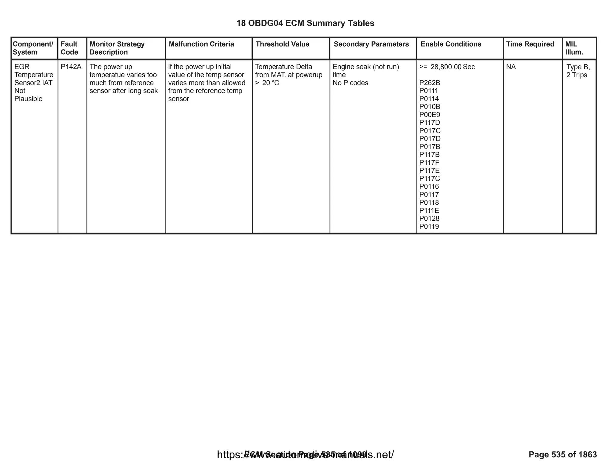
![Component/
System
Fault
Code
Monitor Strategy
Description
Malfunction Criteria Threshold Value Secondary Parameters Enable Conditions Time Required MIL
Illum.
Glow Plug
Positive
Voltage
Circuit
P161E This DTC checks the
circuit for electrical
integrity during
operation.
Glow plugs supply pin
open circuit or shorted
to ground.
Voltage feedback under a
calibratable threshold
Voltage_feedback <
6.00
Test enabled by
calibration;
Key on and engine
running (cranking
excluded);
Battery voltage in range;
Enable_On interface is
true;
Diagnostic system is not
disabled;
[boolean]
1.00
VePMDR_b_RunCrankAc
tive = TRUE;
VeEMDR_b_EngModeCra
nk = FALSE;
VeLVTR_b_RunCrankIgnI
nRange = TRUE;
VeGLOO_b_GlowPlugEn
bld = TRUE;
VeDRER_DiagSystemDs
bl = FALSE;
fail
10.00
samples
over
samples
20.00
Time task: 100
[ms]
Type B,
2 Trips
18 OBDG04 ECM Summary Tables
ECM Section Page 536 of 1090 Page 536 of 1863
https://www.automotive-manuals.net/](https://image.slidesharecdn.com/gmcenginefaultcodesdtc1-230327071418-56d3c5bb/75/18-OBDG04-ECM-Summary-Tables-536-2048.jpg)
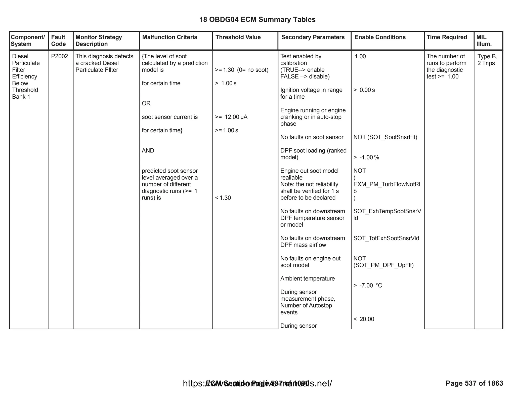
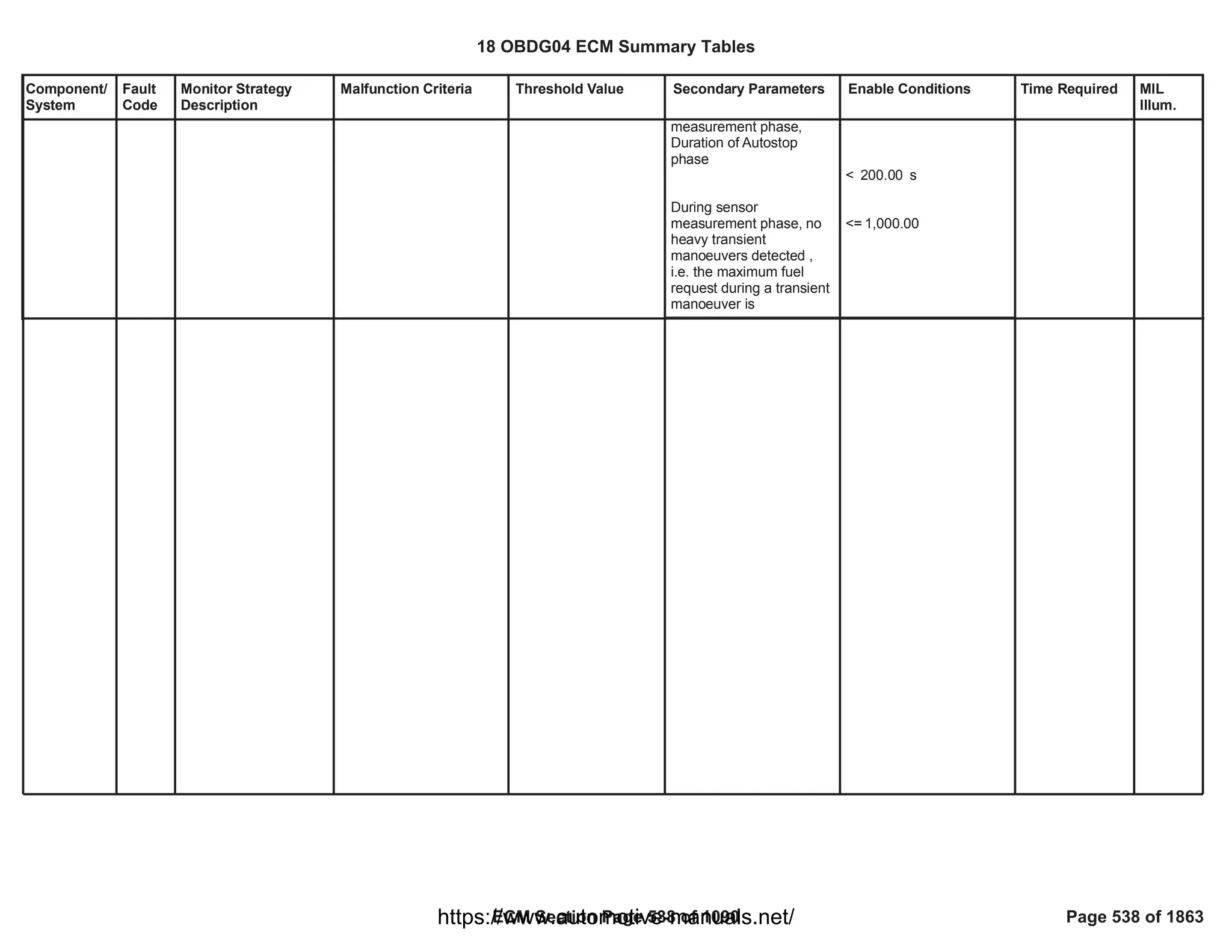
![Component/
System
Fault
Code
Monitor Strategy
Description
Malfunction Criteria Threshold Value Secondary Parameters Enable Conditions Time Required MIL
Illum.
Injector
Positive
Voltage
Control
Circuit
Group 1 Low
Voltage (For
4 Cylinder
Engines)
P2147 This DTC detects a
short circuit to ground
of the high side driver
circuit of the Bank 1
(injector 1 and 4)
Voltage high across High
Side Driver of bank 1
(injector 1 and 4) during
On state indicates short to
ground
impedence between
HS pin of injector 1
and controller ground
<= 0.5 [Ohm]
OR
impedence between
HS pin of injector 4
and controller ground
<= 0.5 [Ohm]
Test enabled by
calibration;
and
Battery voltage
and
Key ON
and
Engine is not cranking
and
Engine Running
and
(
FUL_OutEnblCyl_CiEPS
R_CylinderA
OR
FUL_OutEnblCyl_CiEPS
R_CylinderC
)
and
(
FUL_FuelInjectedCyl_CiE
PSR_CylinderA
OR
FUL_FuelInjectedCyl_CiE
PSR_CylinderC
)
== [Boolean]
1
> [V]
11.00
-
-
>= [s]
1.00
== 0 [Boolean]
== 0 [Boolean]
== TRUE);
== TRUE);
failures out of
5
samples
10
100 ms/sample
Continuous
Type A,
1 Trips
18 OBDG04 ECM Summary Tables
ECM Section Page 539 of 1090 Page 539 of 1863
https://www.automotive-manuals.net/](https://image.slidesharecdn.com/gmcenginefaultcodesdtc1-230327071418-56d3c5bb/75/18-OBDG04-ECM-Summary-Tables-539-2048.jpg)
![Component/
System
Fault
Code
Monitor Strategy
Description
Malfunction Criteria Threshold Value Secondary Parameters Enable Conditions Time Required MIL
Illum.
Injector
Positive
Voltage
Control
Circuit
Group 1
High Voltage
(For 4
Cylinder
Engines)
P2148 This DTC detects a
short circuit to high
voltage of high side
driver circuit of the
Bank 1 (injector 1 and
4)
Voltage low across High
side drive of bank 1
(injector 1 and 4) during
off state indicates short to
power
impedence between
HS pin of injector 1
and controller power
<= 0.5 [Ohm]
OR
impedence between
HS pin of injector 4
and controller power
<= 0.5 [Ohm]
Test enabled by
calibration;
and
Battery voltage
and
Key ON
and
Engine is not cranking
and
Engine Running
and
(
FUL_OutEnblCyl_CiEPS
R_CylinderA
OR
FUL_OutEnblCyl_CiEPS
R_CylinderC
)
and
(
FUL_FuelInjectedCyl_CiE
PSR_CylinderA
OR
FUL_FuelInjectedCyl_CiE
PSR_CylinderC
)
== [Boolean]
1
> [V]
11.00
-
-
>= [s]
1.00
== 0 [Boolean]
== 0 [Boolean]
== TRUE);
== TRUE);
failures out of
5
samples
10
100 ms/sample
Continuous
Type A,
1 Trips
18 OBDG04 ECM Summary Tables
ECM Section Page 540 of 1090 Page 540 of 1863
https://www.automotive-manuals.net/](https://image.slidesharecdn.com/gmcenginefaultcodesdtc1-230327071418-56d3c5bb/75/18-OBDG04-ECM-Summary-Tables-540-2048.jpg)
![Component/
System
Fault
Code
Monitor Strategy
Description
Malfunction Criteria Threshold Value Secondary Parameters Enable Conditions Time Required MIL
Illum.
Injector
Positive
Voltage
Control
Circuit
Group 2 Low
Voltage (For
4 Cylinder
Engines)
P2150 This DTC detects a
short circuit to ground
of the high side driver
circuit of the Bank 2
(injector 2 and 3)
Voltage high across High
Side Driver of bank 2
(injector 2 and 3) during
On state indicates short to
ground
impedence between
HS pin of injector 2
and controller ground
<= 0.5 [Ohm]
OR
impedence between
HS pin of injector 3
and controller ground
<= 0.5 [Ohm]
Test enabled by
calibration;
and
Battery voltage
and
Key ON
and
Engine is not cranking
and
Engine Running
and
(
FUL_OutEnblCyl_CiEPS
R_CylinderD
OR
FUL_OutEnblCyl_CiEPS
R_CylinderB
)
and
(
FUL_FuelInjectedCyl_CiE
PSR_CylinderD
OR
FUL_FuelInjectedCyl_CiE
PSR_CylinderB
)
= [Boolean]
1
> [V]
11.00
-
-
>= [s]
1.00
== 0 [Boolean]
== 0 [Boolean]
== TRUE);
== TRUE);
failures out of
5
samples
10
100 ms/sample
Continuous
Type A,
1 Trips
18 OBDG04 ECM Summary Tables
ECM Section Page 541 of 1090 Page 541 of 1863
https://www.automotive-manuals.net/](https://image.slidesharecdn.com/gmcenginefaultcodesdtc1-230327071418-56d3c5bb/75/18-OBDG04-ECM-Summary-Tables-541-2048.jpg)
![Component/
System
Fault
Code
Monitor Strategy
Description
Malfunction Criteria Threshold Value Secondary Parameters Enable Conditions Time Required MIL
Illum.
Injector
Positive
Voltage
Control
Circuit
Group 2
High Voltage
(For 4
Cylinder
Engines)
P2151 This DTC detects a
short circuit to high
voltage of high side
driver circuit of the
Bank 2 (injector 2 and
3)
Voltage low across High
side drive of bank 2
(injector 2 and 3) during
off state indicates short to
power
impedence between
HS pin of injector 2
and controller power
<= 0.5 [Ohm]
OR
impedence between
HS pin of injector 3
and controller power
<= 0.5 [Ohm]
Test enabled by
calibration;
and
Battery voltage
and
Key ON
and
Engine is not cranking
and
Engine Running
and
(
FUL_OutEnblCyl_CiEPS
R_CylinderD
OR
FUL_OutEnblCyl_CiEPS
R_CylinderB
)
and
(
FUL_FuelInjectedCyl_CiE
PSR_CylinderD
OR
FUL_FuelInjectedCyl_CiE
PSR_CylinderB
)
= [Boolean]
1
> [V]
11.00
-
-
>= [s]
1.00
== 0 [Boolean]
== 0 [Boolean]
== TRUE);
== TRUE);
failures out of
5
samples
10
100 ms/sample
Continuous
Type A,
1 Trips
18 OBDG04 ECM Summary Tables
ECM Section Page 542 of 1090 Page 542 of 1863
https://www.automotive-manuals.net/](https://image.slidesharecdn.com/gmcenginefaultcodesdtc1-230327071418-56d3c5bb/75/18-OBDG04-ECM-Summary-Tables-542-2048.jpg)
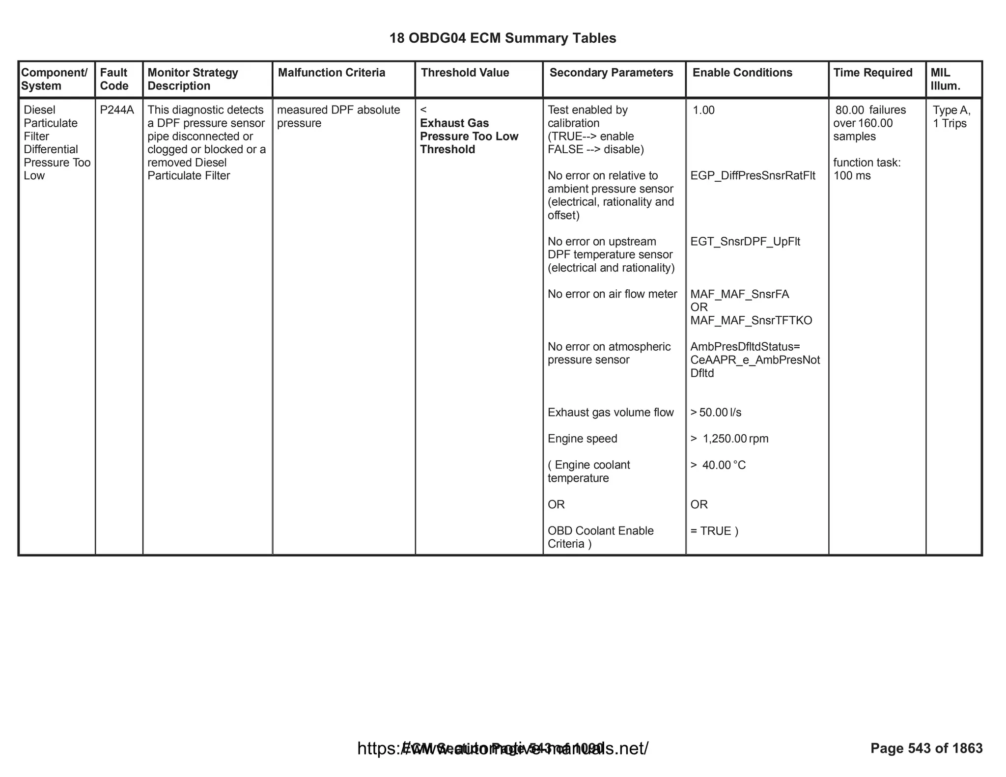
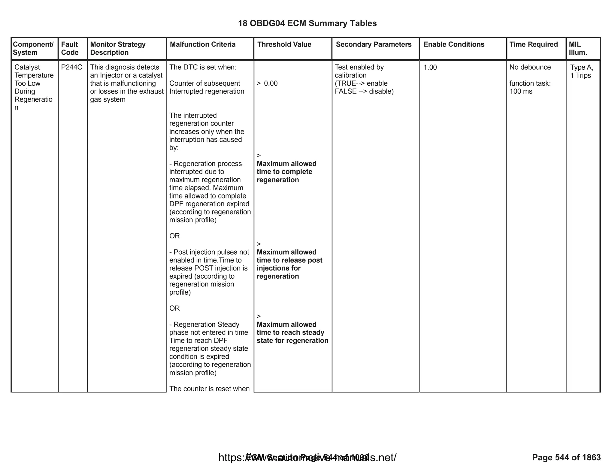
![Component/
System
Fault
Code
Monitor Strategy
Description
Malfunction Criteria Threshold Value Secondary Parameters Enable Conditions Time Required MIL
Illum.
Exhaust Gas
Recirculation
Cooling
System
Performance
(OBDII
market only)
(MDE
applications)
P2457 This monitor checks
the HP EGR Cooler
efficiency deterioration,
that would cause
vehicle's emissions to
exceed specific
emission levels.
HP EGR Cooler Efficiency
(averaged over a
calibrate-able cumulative
transient time) is
compared with a
threshold.
HP EGR Cooler efficiency
is computed as the ratio
between (HP EGR cooler
upstream temperature -
HP EGR cooler
downstream temperature)
and (HP EGR cooler
upstream temperature -
Engine coolant
temperature).
The Engine coolant
temperature used is
coming from the HP EGR
cooler inlet coolant
temperature sensor.
< [%]
80.00 Calibration on diagnostic
enabling
Diagnostic has not run in
current driving cycle yet
PT Relay voltage in range
Engine is running or
cranking
HP EGR cooler upstream
temperature in range
Ambient Temperature
Ambient pressure
Air Control is Active
Engine Coolant
Temperature in range
HP EGR Cooler bypass
not active for a time
HP EGR flow in range
==TRUE
1.00
==TRUE
Powertrain relay voltage >
[V]
11.00
==TRUE
> [°C]
300.00
< [°C]
500.00
>= [°C]
-7.00
>= [kPa]
74.80
Refer to "Air Control
Active" Free Form
> [°C]
60.00
< [°C]
124.00
> [s]
7.00
< [mg/s]
7.00
> [mg/s]
4.00
Test executed
after 175.00
samples are
collected and
their average is
computed
functional task
100 ms
Type B,
2 Trips
18 OBDG04 ECM Summary Tables
ECM Section Page 546 of 1090 Page 546 of 1863
https://www.automotive-manuals.net/](https://image.slidesharecdn.com/gmcenginefaultcodesdtc1-230327071418-56d3c5bb/75/18-OBDG04-ECM-Summary-Tables-546-2048.jpg)
![Component/
System
Fault
Code
Monitor Strategy
Description
Malfunction Criteria Threshold Value Secondary Parameters Enable Conditions Time Required MIL
Illum.
for a time
HP EGR flow estimation is
valid
Engine speed in range
No fault on HP EGR
cooler upstream
temperature sensor
No fault on HP EGR
cooler downstream
temperature sensor
No fault on Ambient
Temperature sensor
No fault on ambient
pressure sensor
No fault on HP EGR
cooler inlet coolant
temperature sensor
No fault on engine speed
No fault on HP EGR
Cooler Bypass
>= [s]
2.00
EGR_VlvTotFlowNotValid
==FALSE
< [rpm]
3,000.00
> [rpm]
1,000.00
==FALSE
CET_UPSS_FA
==FALSE
CET_DNSS_FA
OAT_PtEstFiltFA
==FALSE
AAP_AmbientAirPresDfltd
==FALSE
CEW_TempSnsrInFA
==FALSE
CrankSensor_FA
==FALSE
CEB_ActrCktLoFA
==FALSE
18 OBDG04 ECM Summary Tables
ECM Section Page 547 of 1090 Page 547 of 1863
https://www.automotive-manuals.net/](https://image.slidesharecdn.com/gmcenginefaultcodesdtc1-230327071418-56d3c5bb/75/18-OBDG04-ECM-Summary-Tables-547-2048.jpg)
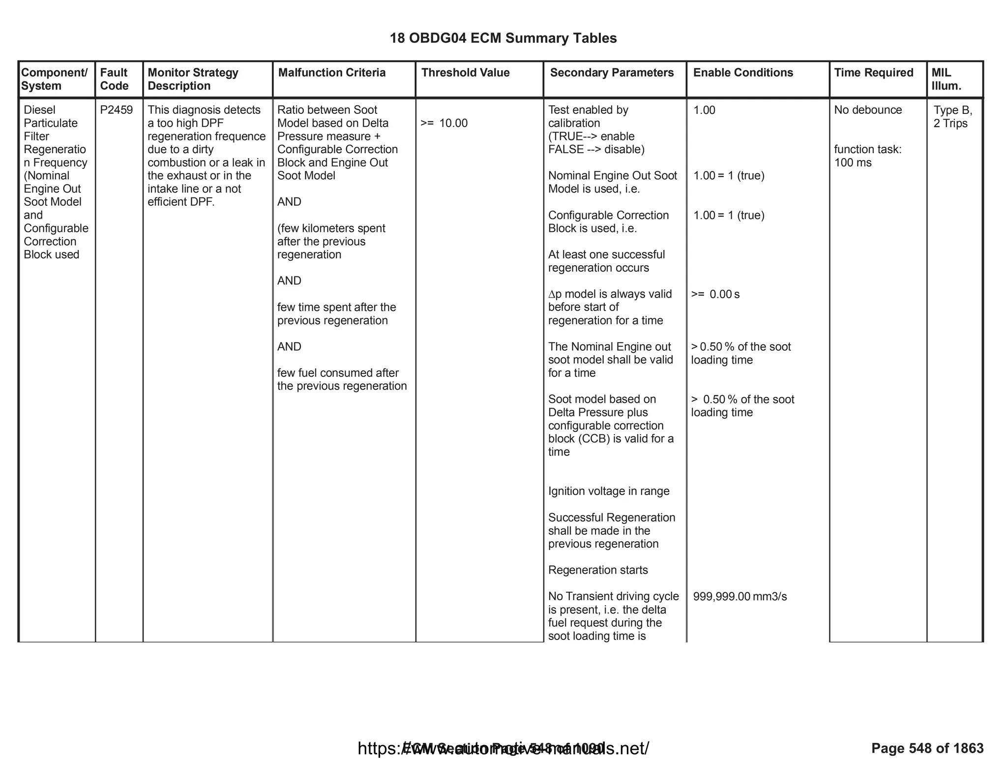
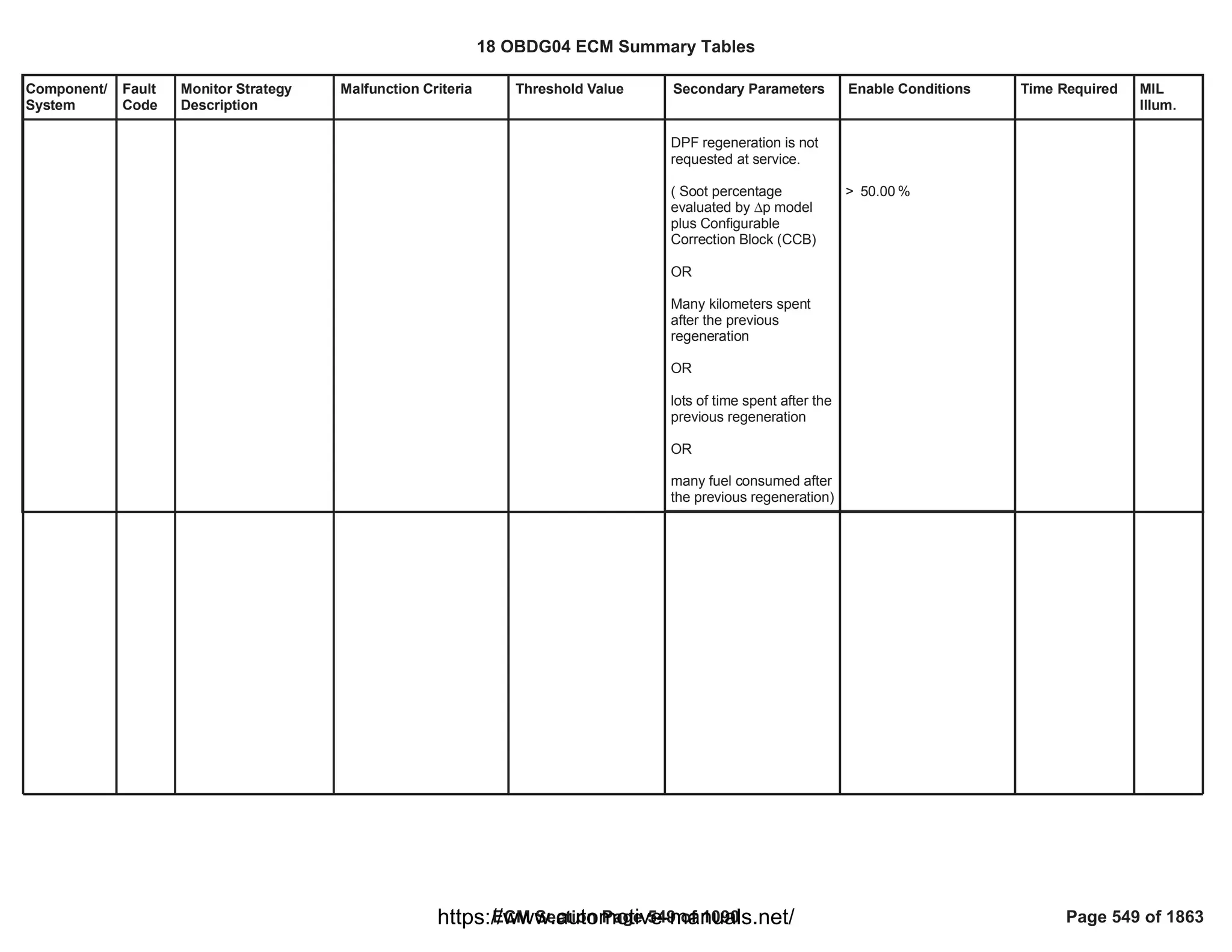
![Component/
System
Fault
Code
Monitor Strategy
Description
Malfunction Criteria Threshold Value Secondary Parameters Enable Conditions Time Required MIL
Illum.
Exhaust Gas
Recirculation
Cooler
Bypass
Valve
Control
Circuit (ECB
Vacuum)
P245A This monitor checks if
the HP EGR cooler
bypass valve command
is in open circuit
Load resistance higher
than a threshold (error
information provided by
HWIO)
> 200 [kOhm] Test enabled by
calibration
System out of the
cranking phase
PT relay supply voltage in
range
Flap is requested in
COOLING mode
Shared High Side driver
driven closed
Diagnostic system
enabled (no clear code or
EOT in progress)
HWIO error status
different from
INDETERMINATE status
Key ON or engine running
== 1.00
> [V]
11.00
24.00
fail counts out of
30.00
sample counts
Function task:
100 ms
Type B,
2 Trips
18 OBDG04 ECM Summary Tables
ECM Section Page 550 of 1090 Page 550 of 1863
https://www.automotive-manuals.net/](https://image.slidesharecdn.com/gmcenginefaultcodesdtc1-230327071418-56d3c5bb/75/18-OBDG04-ECM-Summary-Tables-550-2048.jpg)
![Component/
System
Fault
Code
Monitor Strategy
Description
Malfunction Criteria Threshold Value Secondary Parameters Enable Conditions Time Required MIL
Illum.
Exhaust Gas
Recirculation
Cooler
Bypass
Valve
Control
Circuit Low
(ECB
Vacuum)
P245C This monitor checks if
the HP EGR cooler
bypass valve command
is shorted to ground
Resistance to ground
lower than a threshold
(error information
provided by HWIO)
< 0.5 [Ohm] Test enabled by
calibration
System out of the
cranking phase
PT relay supply voltage in
range
Flap is requested in
COOLING mode
Shared High Side driver
driven closed
Diagnostic system
enabled (no clear code or
EOT in progress)
HWIO error status
different from
INDETERMINATE status
Key ON or engine running
== 1.00
> [V]
11.00
24.00
fail counts out of
30.00
sample counts
Function task:
100 ms
Type B,
2 Trips
18 OBDG04 ECM Summary Tables
ECM Section Page 551 of 1090 Page 551 of 1863
https://www.automotive-manuals.net/](https://image.slidesharecdn.com/gmcenginefaultcodesdtc1-230327071418-56d3c5bb/75/18-OBDG04-ECM-Summary-Tables-551-2048.jpg)
![Component/
System
Fault
Code
Monitor Strategy
Description
Malfunction Criteria Threshold Value Secondary Parameters Enable Conditions Time Required MIL
Illum.
Exhaust Gas
Recirculation
Cooler
Bypass
Valve
Control
Circuit High
(ECB
Vacuum)
P245D This monitor checks if
the HP EGR cooler
bypass valve command
is shorted to power
supply
Resistance to supply
lower than a threshold
(error information
provided by HWIO)
< 0.5 [Ohm] Test enabled by
calibration
System out of the
cranking phase
PT relay supply voltage in
range
Flap is requested in
BYPASS mode
Shared High Side driver
driven closed
Diagnostic system
enabled (no clear code or
EOT in progress)
HWIO error status
different from
INDETERMINATE status
Key ON or engine running
== 1.00
> [V]
11.00
24.00
fail counts out of
30.00
sample counts
Function task:
100 ms
Type B,
2 Trips
18 OBDG04 ECM Summary Tables
ECM Section Page 552 of 1090 Page 552 of 1863
https://www.automotive-manuals.net/](https://image.slidesharecdn.com/gmcenginefaultcodesdtc1-230327071418-56d3c5bb/75/18-OBDG04-ECM-Summary-Tables-552-2048.jpg)
![Component/
System
Fault
Code
Monitor Strategy
Description
Malfunction Criteria Threshold Value Secondary Parameters Enable Conditions Time Required MIL
Illum.
Diesel
Particulate
Filter Soot
Accumulatio
n
P2463 This diagnostic detects
a clogged DPF needing
to be regeneration at
service
Soot model based on
Delta pressure measure
plus configurable
correction block (CCB)
> 133.00 Test enabled by
calibration
(TRUE--> enable
FALSE --> disable)
No fault on DPF pressure
sensor (electrical,
rationality and offset)
No fault on upstream DPF
temperature sensor
(electrical and rationality)
No fault on air flow meter
No fault on atmospheric
pressure sensor
DPF status insootloading
phase (no regeneration
ongoing)
Engine speed
No fault on exhaust mass
flow estimation
Exhaust gas volume flow
greater than a
calibrateable threshold for
more than a calibratable
time
Exhaust gas temperature
at DPF inlet is between
two thresholds for a
minimum calibrateable
time
1.00
EGP_DiffPresSnsrFlt
EGT_SnsrDPF_UpFlt
OR
MAF_MAF_SnsrFA
MAF_MAF_SnsrTFTKO
=
AmbPresDfltdStatus
CeAAPR_e_AmbPresNot
Dfltd
==
DPF_DPF_St
CeDPFR_e_SootLoading
> [rpm]
500.00
EXF_TotExhDPF_UpFA
> [l/s]
24.00
for > [s]
2.00
[DegC] <
0.00
Temperature < 600.00
[DegC]
for > [s]
0.00
failures
120.00
over 150.00
samples
function task:
100 ms
Type A,
1 Trips
18 OBDG04 ECM Summary Tables
ECM Section Page 553 of 1090 Page 553 of 1863
https://www.automotive-manuals.net/](https://image.slidesharecdn.com/gmcenginefaultcodesdtc1-230327071418-56d3c5bb/75/18-OBDG04-ECM-Summary-Tables-553-2048.jpg)
![Component/
System
Fault
Code
Monitor Strategy
Description
Malfunction Criteria Threshold Value Secondary Parameters Enable Conditions Time Required MIL
Illum.
Engine Coolant
Temperature
Ambient Temperature
Soot model based on
Delta Pressure plus
configurable correction
block (CCB) is valid for a
time
Soot model based on
Delta Pressure is always
valid for a time
Distance since last
completed regeneration
> [DegC]
0.00
> [DegC]
-40.00
> = % of the soot
0.20
loading
>= s
15.00
> km
5.00
18 OBDG04 ECM Summary Tables
ECM Section Page 554 of 1090 Page 554 of 1863
https://www.automotive-manuals.net/](https://image.slidesharecdn.com/gmcenginefaultcodesdtc1-230327071418-56d3c5bb/75/18-OBDG04-ECM-Summary-Tables-554-2048.jpg)
![Component/
System
Fault
Code
Monitor Strategy
Description
Malfunction Criteria Threshold Value Secondary Parameters Enable Conditions Time Required MIL
Illum.
Exhaust Gas
Recirculation
Cooler
Bypass
Valve
Control
Stuck (ECB
Vacuum)
P24A5 This monitor check if
the EGR Cooler
Bypass is mechanically
stuck in bypass or
cooling mode
Gradient temperature
downstream EGR cooler
bypass when the EGR
cooler bypass flap is
moved from cooling to
bypass and from bypass
to cooling position < low
threshold
<
[°C]
P24A5: Gradient
Temperature
Threshold
Diagnosis is enabled by
calibration
Engine speed
Vehicle speed
EGR valve total flow
Air Control Active
Engine Coolant
Temperature
Combustion Mode
Fuel value
Fuel gradient
Gradient filtered
downstream EGR cooler
temperature, with
hysteresis
== 1.00
>= [rpm]
1,000.00
< [rpm]
3,000.00
>= [kph]
10.00
< [kph]
128.00
>= [mg/s]
4.00
< [mg/s]
30.00
AIC_AirCntrlShtOffAction
==Ce_AICR_e_CntrlActv
>= [°C]
60.00
< [°C]
124.00
==C2,C3,
SCR_Temp1,SCR_Temp,
SCR_Temp3
>= [mm^3]
5.00
< [mm^3]
50.00
>= [mm^3]
-3.00
< [mm^3]
3.00
< [°C/s] (ENABLE)
29.00
> [°C/s] (DISABLE)
30.00
Test is executed
after +
5.00
+
5.00 5.00
sample counts
Function task:
100 ms
Type B,
2 Trips
18 OBDG04 ECM Summary Tables
ECM Section Page 555 of 1090 Page 555 of 1863
https://www.automotive-manuals.net/](https://image.slidesharecdn.com/gmcenginefaultcodesdtc1-230327071418-56d3c5bb/75/18-OBDG04-ECM-Summary-Tables-555-2048.jpg)
![Component/
System
Fault
Code
Monitor Strategy
Description
Malfunction Criteria Threshold Value Secondary Parameters Enable Conditions Time Required MIL
Illum.
EGR upstream
temperature
Diagnostic system
enabled (no clear code or
EOT in progress)
No faults detected on
vehicle speed sensor
No faults detected on
engine coolant
temperature sensor
No faults detected on
downstream HP EGR
Cooler temperature
sensor
No faults detected on
upstream HP EGR Cooler
temperature sensor
No faults detected on HP
EGR Cooler Bypass
actuator
No faults detected on HP
EGR valve
>= [°C]
350.00
< [°C]
750.00
VehicleSpeedSensor_FA
==FALSE
=FALSE
ECT_Sensor_FA
==FALSE
CET_DNSS_FA
==FALSE
CET_UPSS_FA
==FALSE
CEB_ActrCktFA
EGR_PstnDvtnFA
==FALSE
18 OBDG04 ECM Summary Tables
ECM Section Page 556 of 1090 Page 556 of 1863
https://www.automotive-manuals.net/](https://image.slidesharecdn.com/gmcenginefaultcodesdtc1-230327071418-56d3c5bb/75/18-OBDG04-ECM-Summary-Tables-556-2048.jpg)
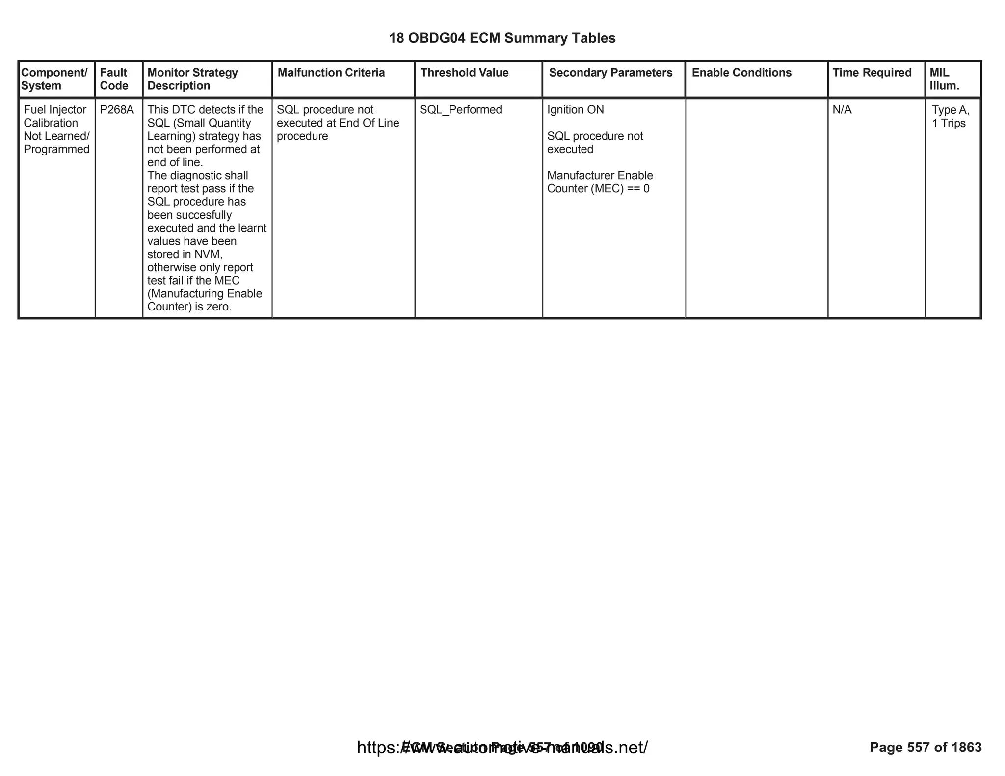
![Component/
System
Fault
Code
Monitor Strategy
Description
Malfunction Criteria Threshold Value Secondary Parameters Enable Conditions Time Required MIL
Illum.
Cylinder 1
Injector Data
Incompatible
P268C This DTC detects if the
EIA (End of line Injector
Adjustment) code for
cylinder 1 has not been
programmed.
The diagnostic shall
report test pass if the
EIA code has been
succesfully
programmed, otherwise
only report test fail if
the MEC
(Manufacturing Enable
Counter) is zero.
Cylinder 1 EIA code not
written via DID (DID $60).
N/A Ignition ON
Diagnosis enabled via
calibration
Manufacturer Enable
Counter (MEC) == 0
[Boolean]
1.00
N/A Type A,
1 Trips
18 OBDG04 ECM Summary Tables
ECM Section Page 558 of 1090 Page 558 of 1863
https://www.automotive-manuals.net/](https://image.slidesharecdn.com/gmcenginefaultcodesdtc1-230327071418-56d3c5bb/75/18-OBDG04-ECM-Summary-Tables-558-2048.jpg)
![Component/
System
Fault
Code
Monitor Strategy
Description
Malfunction Criteria Threshold Value Secondary Parameters Enable Conditions Time Required MIL
Illum.
Cylinder 2
Injector Data
Incompatible
P268D This DTC detects if the
EIA (End of line Injector
Adjustment) code for
cylinder 2 has not been
programmed.
The diagnostic shall
report test pass if the
EIA code has been
succesfully
programmed, otherwise
only report test fail if
the MEC
(Manufacturing Enable
Counter) is zero.
Cylinder 2 EIA code not
written via DID (DID $61).
N/A Ignition ON
Diagnosis enabled via
calibration
Manufacturer Enable
Counter (MEC) == 0
[Boolean]
1.00
N/A Type A,
1 Trips
18 OBDG04 ECM Summary Tables
ECM Section Page 559 of 1090 Page 559 of 1863
https://www.automotive-manuals.net/](https://image.slidesharecdn.com/gmcenginefaultcodesdtc1-230327071418-56d3c5bb/75/18-OBDG04-ECM-Summary-Tables-559-2048.jpg)
![Component/
System
Fault
Code
Monitor Strategy
Description
Malfunction Criteria Threshold Value Secondary Parameters Enable Conditions Time Required MIL
Illum.
Cylinder 3
Injector Data
Incompatible
P268E This DTC detects if the
EIA (End of line Injector
Adjustment) code for
cylinder 3 has not been
programmed.
The diagnostic shall
report test pass if the
EIA code has been
succesfully
programmed, otherwise
only report test fail if
the MEC
(Manufacturing Enable
Counter) is zero.
Cylinder 3 EIA code not
written via DID (DID $62).
N/A Ignition ON
Diagnosis enabled via
calibration
Manufacturer Enable
Counter (MEC) == 0
[Boolean]
1.00
N/A Type A,
1 Trips
18 OBDG04 ECM Summary Tables
ECM Section Page 560 of 1090 Page 560 of 1863
https://www.automotive-manuals.net/](https://image.slidesharecdn.com/gmcenginefaultcodesdtc1-230327071418-56d3c5bb/75/18-OBDG04-ECM-Summary-Tables-560-2048.jpg)
![Component/
System
Fault
Code
Monitor Strategy
Description
Malfunction Criteria Threshold Value Secondary Parameters Enable Conditions Time Required MIL
Illum.
Cylinder 4
Injector Data
Incompatible
P268F This DTC detects if the
EIA (End of line Injector
Adjustment) code for
cylinder 4 has not been
programmed.
The diagnostic shall
report test pass if the
EIA code has been
succesfully
programmed, otherwise
only report test fail if
the MEC
(Manufacturing Enable
Counter) is zero.
Cylinder 4 EIA code not
written via DID (DID $63).
N/A Ignition ON
Diagnosis enabled via
calibration
Manufacturer Enable
Counter (MEC) == 0
[Boolean]
1.00
N/A Type A,
1 Trips
18 OBDG04 ECM Summary Tables
ECM Section Page 561 of 1090 Page 561 of 1863
https://www.automotive-manuals.net/](https://image.slidesharecdn.com/gmcenginefaultcodesdtc1-230327071418-56d3c5bb/75/18-OBDG04-ECM-Summary-Tables-561-2048.jpg)
![Component/
System
Fault
Code
Monitor Strategy
Description
Malfunction Criteria Threshold Value Secondary Parameters Enable Conditions Time Required MIL
Illum.
Cylinder 5
Injector Data
Incompatible
P2690 This DTC detects if the
EIA (End of line Injector
Adjustment) code for
cylinder 5 has not been
programmed.
The diagnostic shall
report test pass if the
EIA code has been
succesfully
programmed, otherwise
only report test fail if
the MEC
(Manufacturing Enable
Counter) is zero.
Cylinder 5 EIA code not
written via DID (DID $64).
N/A Ignition ON
Diagnosis enabled via
calibration
Manufacturer Enable
Counter (MEC) == 0
[Boolean]
1.00
N/A Type A,
1 Trips
18 OBDG04 ECM Summary Tables
ECM Section Page 562 of 1090 Page 562 of 1863
https://www.automotive-manuals.net/](https://image.slidesharecdn.com/gmcenginefaultcodesdtc1-230327071418-56d3c5bb/75/18-OBDG04-ECM-Summary-Tables-562-2048.jpg)
![Component/
System
Fault
Code
Monitor Strategy
Description
Malfunction Criteria Threshold Value Secondary Parameters Enable Conditions Time Required MIL
Illum.
Cylinder 6
Injector Data
Incompatible
P2691 This DTC detects if the
EIA (End of line Injector
Adjustment) code for
cylinder 6 has not been
programmed.
The diagnostic shall
report test pass if the
EIA code has been
succesfully
programmed, otherwise
only report test fail if
the MEC
(Manufacturing Enable
Counter) is zero.
Cylinder 6 EIA code not
written via DID (DID $65).
N/A Ignition ON
Diagnosis enabled via
calibration
Manufacturer Enable
Counter (MEC) == 0
[Boolean]
1.00
N/A Type A,
1 Trips
18 OBDG04 ECM Summary Tables
ECM Section Page 563 of 1090 Page 563 of 1863
https://www.automotive-manuals.net/](https://image.slidesharecdn.com/gmcenginefaultcodesdtc1-230327071418-56d3c5bb/75/18-OBDG04-ECM-Summary-Tables-563-2048.jpg)
![Component/
System
Fault
Code
Monitor Strategy
Description
Malfunction Criteria Threshold Value Secondary Parameters Enable Conditions Time Required MIL
Illum.
Cylinder 7
Injector Data
Incompatible
P2692 This DTC detects if the
EIA (End of line Injector
Adjustment) code for
cylinder 7 has not been
programmed.
The diagnostic shall
report test pass if the
EIA code has been
succesfully
programmed, otherwise
only report test fail if
the MEC
(Manufacturing Enable
Counter) is zero.
Cylinder 7 EIA code not
written via DID (DID $66).
N/A Ignition ON
Diagnosis enabled via
calibration
Manufacturer Enable
Counter (MEC) == 0
[Boolean]
1.00
N/A Type A,
1 Trips
18 OBDG04 ECM Summary Tables
ECM Section Page 564 of 1090 Page 564 of 1863
https://www.automotive-manuals.net/](https://image.slidesharecdn.com/gmcenginefaultcodesdtc1-230327071418-56d3c5bb/75/18-OBDG04-ECM-Summary-Tables-564-2048.jpg)
![Component/
System
Fault
Code
Monitor Strategy
Description
Malfunction Criteria Threshold Value Secondary Parameters Enable Conditions Time Required MIL
Illum.
Cylinder 8
Injector Data
Incompatible
P2693 This DTC detects if the
EIA (End of line Injector
Adjustment) code for
cylinder 8 has not been
programmed.
The diagnostic shall
report test pass if the
EIA code has been
succesfully
programmed, otherwise
only report test fail if
the MEC
(Manufacturing Enable
Counter) is zero.
Cylinder 8 EIA code not
written via DID (DID $67).
N/A Ignition ON
Diagnosis enabled via
calibration
Manufacturer Enable
Counter (MEC) == 0
[Boolean]
1.00
N/A Type A,
1 Trips
18 OBDG04 ECM Summary Tables
ECM Section Page 565 of 1090 Page 565 of 1863
https://www.automotive-manuals.net/](https://image.slidesharecdn.com/gmcenginefaultcodesdtc1-230327071418-56d3c5bb/75/18-OBDG04-ECM-Summary-Tables-565-2048.jpg)
![Component/
System
Fault
Code
Monitor Strategy
Description
Malfunction Criteria Threshold Value Secondary Parameters Enable Conditions Time Required MIL
Illum.
Cylinder 5
Injection
Timing
Perfomance
- Over
Retarded
P01D3 This diagnosis is able
to detect an excessive
negative drift on fuel
injection quantity and
timing affecting injector
5.
During Diesel Fuel Cut-
off conditions SQA
command the injection
of a known quantity on
one injector (e.g.
1,5mm^3) and checks,
by means of crank-
wheel sensor, the
angular acceleration
produced during the
combustion phase. By
comparing the angular
acceleration value
produced during the
combustion phase with
the angular
acceleration that would
be produced during the
combustion of a
nominal fuel quantity
(e.g. 1,5mm3), the SQA
is able to calculate the
drift, in term of
energizing time, on
injector 5.
Several injections, with
different injection
quantities, are
performed in order to
extrapolate the results
and obtain the injector
behaviour in the small
quantity area.
This energizing time is
then used for the
Suspicious confidence
level of tested injector (To
fail suspicious), function
of Current Energizing time
calculated with SSQA and
delta Energizing time
calculated in the previous
test:
KtFADD_Pct_SSQA_InjS
uspConfLvl
(Delta Enegizing Time,
Delta Energizing Time
old)
In case the first test fails:
Delta Energizing time
calculated by VSQA (To
fail Validation)
< [%]
20.00
> [us]
1,000.00
SQA Diagnosis enabled
SSQA and VSQA enabled
Baro Pressure
Ambient temp
No Low Fuel level tank
indication
AND
Boolean Flag used to
enable low fuel level
check is TRUE
(x)SQA injection
management enabled
1.00
1.00
>= [kPa]
0.00
>= [°C]
0.00
LowFuelConditionDiagnos
tic
0.00
FAD_XSQA_LrnCondEnbl
Inj_To_PassFail_
SSQA Number of
injections in case
sospicious pass
or (if sospicious
fails)
Inj_To_PassFail_
SSQA
+Inj_To_PassFail
_VSQA number
of injections to
pass or fail
validation
Once per Trip if
suspicious and
validations (in
case of
sospicious
injectors
detected) have
been already
completed in the
previous driving
cycle, otherwise
the diagnosis
starts from the
interrupted
status.
Sample Rate: [1
Sample every
cylinder firing
event].
Type B,
2 Trips
18 OBDG04 ECM Summary Tables
ECM Section Page 566 of 1090 Page 566 of 1863
https://www.automotive-manuals.net/](https://image.slidesharecdn.com/gmcenginefaultcodesdtc1-230327071418-56d3c5bb/75/18-OBDG04-ECM-Summary-Tables-566-2048.jpg)
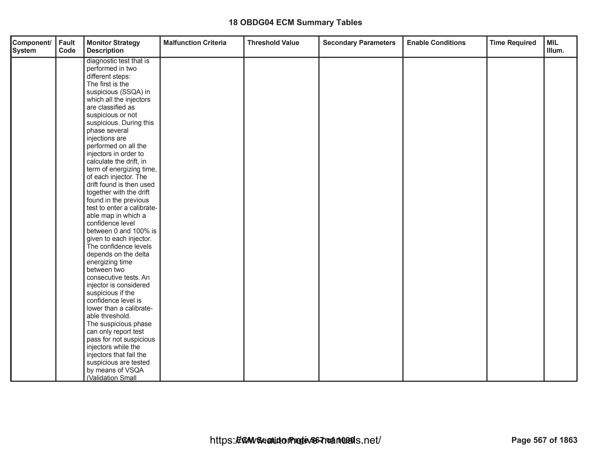

![Component/
System
Fault
Code
Monitor Strategy
Description
Malfunction Criteria Threshold Value Secondary Parameters Enable Conditions Time Required MIL
Illum.
Cylinder 5
Injection
Timing
Perfomance
- Over
Advanced
P01D4 This diagnosis is able
to detect an excessive
positive drift on fuel
injection quantity and
timing affecting injector
5.
During Diesel Fuel Cut-
off conditions SQA
command the injection
of a known quantity on
one injector (e.g.
1,5mm^3) and checks,
by means of crank-
wheel sensor, the
angular acceleration
produced during the
combustion phase. By
comparing the angular
acceleration value
produced during the
combustion phase with
the angular
acceleration that would
be produced during the
combustion of a
nominal fuel quantity
(e.g. 1,5mm3), the SQA
is able to calculate the
drift, in term of
energizing time, on
injector 5.
Several injections, with
different injection
quantities, are
performed in order to
extrapolate the results
and obtain the injector
behaviour in the small
quantity area.
This energizing time is
then used for the
Suspicious confidence
level of tested injector (To
fail suspicious), function
of Current Energizing time
calculated with SSQA and
delta Energizing time
calculated in the previous
test:
KtFADD_Pct_SSQA_InjS
uspConfLvl
(Delta Enegizing Time,
Delta Energizing Time
old)
In case the first test fails:
Delta Energizing time
calculated by VSQA (To
fail Validation)
< [%]
20.00
< [us]
-1,000.00
SQA Diagnosis enabled
SSQA and VSQA enabled
Baro Pressure
Ambient temp
No Low Fuel level tank
indication
AND
Boolean Flag used to
enable low fuel level
check is TRUE
(x)SQA injection
management enabled
1.00
1.00
>= [kPa]
0.00
>= [°C]
0.00
LowFuelConditionDiagnos
tic
0.00
FAD_XSQA_LrnCondEnbl
Inj_To_PassFail_
SSQA Number of
injections in case
sospicious pass
or (if sospicious
fails)
Inj_To_PassFail_
SSQA
+Inj_To_PassFail
_VSQA number
of injections to
pass or fail
validation.
Once per Trip if
suspicious and
validations (in
case of
sospicious
injectors
detected) have
been already
completed in the
previous driving
cycle, otherwise
the diagnosis
starts from the
interrupted
status.
Sample Rate: [1
Sample every
cylinder firing
event].
Type B,
2 Trips
18 OBDG04 ECM Summary Tables
ECM Section Page 569 of 1090 Page 569 of 1863
https://www.automotive-manuals.net/](https://image.slidesharecdn.com/gmcenginefaultcodesdtc1-230327071418-56d3c5bb/75/18-OBDG04-ECM-Summary-Tables-569-2048.jpg)


![Component/
System
Fault
Code
Monitor Strategy
Description
Malfunction Criteria Threshold Value Secondary Parameters Enable Conditions Time Required MIL
Illum.
Cylinder 6
Injection
Timing
Perfomance
- Over
Retarded
P01D5 This diagnosis is able
to detect an excessive
negative drift on fuel
injection quantity and
timing affecting injector
6.
During Diesel Fuel Cut-
off conditions SQA
command the injection
of a known quantity on
one injector (e.g.
1,5mm^3) and checks,
by means of crank-
wheel sensor, the
angular acceleration
produced during the
combustion phase. By
comparing the angular
acceleration value
produced during the
combustion phase with
the angular
acceleration that would
be produced during the
combustion of a
nominal fuel quantity
(e.g. 1,5mm3), the SQA
is able to calculate the
drift, in term of
energizing time, on
injector 6.
Several injections, with
different injection
quantities, are
performed in order to
extrapolate the results
and obtain the injector
behaviour in the small
quantity area.
This energizing time is
then used for the
Suspicious confidence
level of tested injector (To
fail suspicious), function
of Current Energizing time
calculated with SSQA and
delta Energizing time
calculated in the previous
test:
KtFADD_Pct_SSQA_InjS
uspConfLvl
(Delta Enegizing Time,
Delta Energizing Time
old)
In case the first test fails:
Delta Energizing time
calculated by VSQA (To
fail Validation)
< [%]
20.00
> [us]
1,000.00
SQA Diagnosis enabled
SSQA and VSQA enabled
Baro Pressure
Ambient temp
No Low Fuel level tank
indication
AND
Boolean Flag used to
enable low fuel level
check is TRUE
(x)SQA injection
management enabled
1.00
1.00
>= [kPa]
0.00
>= [°C]
0.00
LowFuelConditionDiagnos
tic
0.00
FAD_XSQA_LrnCondEnbl
Inj_To_PassFail_
SSQA Number of
injections in case
sospicious pass
or (if sospicious
fails)
Inj_To_PassFail_
SSQA
+Inj_To_PassFail
_VSQA number
of injections to
pass or fail
validation
Once per Trip if
suspicious and
validations (in
case of
sospicious
injectors
detected) have
been already
completed in the
previous driving
cycle, otherwise
the diagnosis
starts from the
interrupted
status.
Sample Rate: [1
Sample every
cylinder firing
event].
Type B,
2 Trips
18 OBDG04 ECM Summary Tables
ECM Section Page 572 of 1090 Page 572 of 1863
https://www.automotive-manuals.net/](https://image.slidesharecdn.com/gmcenginefaultcodesdtc1-230327071418-56d3c5bb/75/18-OBDG04-ECM-Summary-Tables-572-2048.jpg)


![Component/
System
Fault
Code
Monitor Strategy
Description
Malfunction Criteria Threshold Value Secondary Parameters Enable Conditions Time Required MIL
Illum.
Cylinder 6
Injection
Timing
Perfomance
- Over
Advanced
P01D6 This diagnosis is able
to detect an excessive
positive drift on fuel
injection quantity and
timing affecting injector
6.
During Diesel Fuel Cut-
off conditions SQA
command the injection
of a known quantity on
one injector (e.g.
1,5mm^3) and checks,
by means of crank-
wheel sensor, the
angular acceleration
produced during the
combustion phase. By
comparing the angular
acceleration value
produced during the
combustion phase with
the angular
acceleration that would
be produced during the
combustion of a
nominal fuel quantity
(e.g. 1,5mm3), the SQA
is able to calculate the
drift, in term of
energizing time, on
injector 6.
Several injections, with
different injection
quantities, are
performed in order to
extrapolate the results
and obtain the injector
behaviour in the small
quantity area.
This energizing time is
then used for the
Suspicious confidence
level of tested injector (To
fail suspicious), function
of Current Energizing time
calculated with SSQA and
delta Energizing time
calculated in the previous
test:
KtFADD_Pct_SSQA_InjS
uspConfLvl
(Delta Enegizing Time,
Delta Energizing Time
old)
In case the first test fails:
Delta Energizing time
calculated by VSQA (To
fail Validation)
< [%]
20.00
< [us]
-1,000.00
SQA Diagnosis enabled
SSQA and VSQA enabled
Baro Pressure
Ambient temp
No Low Fuel level tank
indication
AND
Boolean Flag used to
enable low fuel level
check is TRUE
(x)SQA injection
management enabled
1.00
1.00
>= [kPa]
0.00
>= [°C]
0.00
LowFuelConditionDiagnos
tic
0.00
FAD_XSQA_LrnCondEnbl
Inj_To_PassFail_
SSQA Number of
injections in case
sospicious pass
or (if sospicious
fails)
Inj_To_PassFail_
SSQA
+Inj_To_PassFail
_VSQA number
of injections to
pass or fail
validation.
Once per Trip if
suspicious and
validations (in
case of
sospicious
injectors
detected) have
been already
completed in the
previous driving
cycle, otherwise
the diagnosis
starts from the
interrupted
status.
Sample Rate: [1
Sample every
cylinder firing
event].
Type B,
2 Trips
18 OBDG04 ECM Summary Tables
ECM Section Page 575 of 1090 Page 575 of 1863
https://www.automotive-manuals.net/](https://image.slidesharecdn.com/gmcenginefaultcodesdtc1-230327071418-56d3c5bb/75/18-OBDG04-ECM-Summary-Tables-575-2048.jpg)


![Component/
System
Fault
Code
Monitor Strategy
Description
Malfunction Criteria Threshold Value Secondary Parameters Enable Conditions Time Required MIL
Illum.
Cylinder 7
Injection
Timing
Perfomance
- Over
Retarded
P01D7 This diagnosis is able
to detect an excessive
negative drift on fuel
injection quantity and
timing affecting injector
7.
During Diesel Fuel Cut-
off conditions SQA
command the injection
of a known quantity on
one injector (e.g.
1,5mm^3) and checks,
by means of crank-
wheel sensor, the
angular acceleration
produced during the
combustion phase. By
comparing the angular
acceleration value
produced during the
combustion phase with
the angular
acceleration that would
be produced during the
combustion of a
nominal fuel quantity
(e.g. 1,5mm3), the SQA
is able to calculate the
drift, in term of
energizing time, on
injector 7.
Several injections, with
different injection
quantities, are
performed in order to
extrapolate the results
and obtain the injector
behaviour in the small
quantity area.
This energizing time is
then used for the
Suspicious confidence
level of tested injector (To
fail suspicious), function
of Current Energizing time
calculated with SSQA and
delta Energizing time
calculated in the previous
test:
KtFADD_Pct_SSQA_InjS
uspConfLvl
(Delta Enegizing Time,
Delta Energizing Time
old)
In case the first test fails:
Delta Energizing time
calculated by VSQA (To
fail Validation)
< [%]
20.00
> [us]
1,000.00
SQA Diagnosis enabled
SSQA and VSQA enabled
Baro Pressure
Ambient temp
No Low Fuel level tank
indication
AND
Boolean Flag used to
enable low fuel level
check is TRUE
(x)SQA injection
management enabled
1.00
1.00
>= [kPa]
0.00
>= [°C]
0.00
LowFuelConditionDiagnos
tic
0.00
FAD_XSQA_LrnCondEnbl
Inj_To_PassFail_
SSQA Number of
injections in case
sospicious pass
or (if sospicious
fails)
Inj_To_PassFail_
SSQA
+Inj_To_PassFail
_VSQA number
of injections to
pass or fail
validation
Once per Trip if
suspicious and
validations (in
case of
sospicious
injectors
detected) have
been already
completed in the
previous driving
cycle, otherwise
the diagnosis
starts from the
interrupted
status.
Sample Rate: [1
Sample every
cylinder firing
event].
Type B,
2 Trips
18 OBDG04 ECM Summary Tables
ECM Section Page 578 of 1090 Page 578 of 1863
https://www.automotive-manuals.net/](https://image.slidesharecdn.com/gmcenginefaultcodesdtc1-230327071418-56d3c5bb/75/18-OBDG04-ECM-Summary-Tables-578-2048.jpg)


![Component/
System
Fault
Code
Monitor Strategy
Description
Malfunction Criteria Threshold Value Secondary Parameters Enable Conditions Time Required MIL
Illum.
Cylinder 7
Injection
Timing
Perfomance
- Over
Advanced
P01D8 This diagnosis is able
to detect an excessive
positive drift on fuel
injection quantity and
timing affecting injector
7.
During Diesel Fuel Cut-
off conditions SQA
command the injection
of a known quantity on
one injector (e.g.
1,5mm^3) and checks,
by means of crank-
wheel sensor, the
angular acceleration
produced during the
combustion phase. By
comparing the angular
acceleration value
produced during the
combustion phase with
the angular
acceleration that would
be produced during the
combustion of a
nominal fuel quantity
(e.g. 1,5mm3), the SQA
is able to calculate the
drift, in term of
energizing time, on
injector 7.
Several injections, with
different injection
quantities, are
performed in order to
extrapolate the results
and obtain the injector
behaviour in the small
quantity area.
This energizing time is
then used for the
Suspicious confidence
level of tested injector (To
fail suspicious), function
of Current Energizing time
calculated with SSQA and
delta Energizing time
calculated in the previous
test:
KtFADD_Pct_SSQA_InjS
uspConfLvl
(Delta Enegizing Time,
Delta Energizing Time
old)
In case the first test fails:
Delta Energizing time
calculated by VSQA (To
fail Validation)
< [%]
20.00
< [us]
-1,000.00
SQA Diagnosis enabled
SSQA and VSQA enabled
Baro Pressure
Ambient temp
No Low Fuel level tank
indication
AND
Boolean Flag used to
enable low fuel level
check is TRUE
(x)SQA injection
management enabled
1.00
1.00
>= [kPa]
0.00
>= [°C]
0.00
LowFuelConditionDiagnos
tic
0.00
FAD_XSQA_LrnCondEnbl
Inj_To_PassFail_
SSQA Number of
injections in case
sospicious pass
or (if sospicious
fails)
Inj_To_PassFail_
SSQA
+Inj_To_PassFail
_VSQA number
of injections to
pass or fail
validation.
Once per Trip if
suspicious and
validations (in
case of
sospicious
injectors
detected) have
been already
completed in the
previous driving
cycle, otherwise
the diagnosis
starts from the
interrupted
status.
Sample Rate: [1
Sample every
cylinder firing
event].
Type B,
2 Trips
18 OBDG04 ECM Summary Tables
ECM Section Page 581 of 1090 Page 581 of 1863
https://www.automotive-manuals.net/](https://image.slidesharecdn.com/gmcenginefaultcodesdtc1-230327071418-56d3c5bb/75/18-OBDG04-ECM-Summary-Tables-581-2048.jpg)


![Component/
System
Fault
Code
Monitor Strategy
Description
Malfunction Criteria Threshold Value Secondary Parameters Enable Conditions Time Required MIL
Illum.
Cylinder 8
Injection
Timing
Perfomance
- Over
Retarded
P01D9 This diagnosis is able
to detect an excessive
negative drift on fuel
injection quantity and
timing affecting injector
8.
During Diesel Fuel Cut-
off conditions SQA
command the injection
of a known quantity on
one injector (e.g.
1,5mm^3) and checks,
by means of crank-
wheel sensor, the
angular acceleration
produced during the
combustion phase. By
comparing the angular
acceleration value
produced during the
combustion phase with
the angular
acceleration that would
be produced during the
combustion of a
nominal fuel quantity
(e.g. 1,5mm3), the SQA
is able to calculate the
drift, in term of
energizing time, on
injector 8.
Several injections, with
different injection
quantities, are
performed in order to
extrapolate the results
and obtain the injector
behaviour in the small
quantity area.
This energizing time is
then used for the
Suspicious confidence
level of tested injector (To
fail suspicious), function
of Current Energizing time
calculated with SSQA and
delta Energizing time
calculated in the previous
test:
KtFADD_Pct_SSQA_InjS
uspConfLvl
(Delta Enegizing Time,
Delta Energizing Time
old)
In case the first test fails:
Delta Energizing time
calculated by VSQA (To
fail Validation)
< [%]
20.00
> [us]
1,000.00
SQA Diagnosis enabled
SSQA and VSQA enabled
Baro Pressure
Ambient temp
No Low Fuel level tank
indication
AND
Boolean Flag used to
enable low fuel level
check is TRUE
(x)SQA injection
management enabled
1.00
1.00
>= [kPa]
0.00
>= [°C]
0.00
LowFuelConditionDiagnos
tic
0.00
FAD_XSQA_LrnCondEnbl
Inj_To_PassFail_
SSQA Number of
injections in case
sospicious pass
or (if sospicious
fails)
Inj_To_PassFail_
SSQA
+Inj_To_PassFail
_VSQA number
of injections to
pass or fail
validation
Once per Trip if
suspicious and
validations (in
case of
sospicious
injectors
detected) have
been already
completed in the
previous driving
cycle, otherwise
the diagnosis
starts from the
interrupted
status.
Sample Rate: [1
Sample every
cylinder firing
event].
Type B,
2 Trips
18 OBDG04 ECM Summary Tables
ECM Section Page 584 of 1090 Page 584 of 1863
https://www.automotive-manuals.net/](https://image.slidesharecdn.com/gmcenginefaultcodesdtc1-230327071418-56d3c5bb/75/18-OBDG04-ECM-Summary-Tables-584-2048.jpg)


![Component/
System
Fault
Code
Monitor Strategy
Description
Malfunction Criteria Threshold Value Secondary Parameters Enable Conditions Time Required MIL
Illum.
Cylinder 8
Injection
Timing
Perfomance
- Over
Advanced
P01DA This diagnosis is able
to detect an excessive
positive drift on fuel
injection quantity and
timing affecting injector
8.
During Diesel Fuel Cut-
off conditions SQA
command the injection
of a known quantity on
one injector (e.g.
1,5mm^3) and checks,
by means of crank-
wheel sensor, the
angular acceleration
produced during the
combustion phase. By
comparing the angular
acceleration value
produced during the
combustion phase with
the angular
acceleration that would
be produced during the
combustion of a
nominal fuel quantity
(e.g. 1,5mm3), the SQA
is able to calculate the
drift, in term of
energizing time, on
injector 8.
Several injections, with
different injection
quantities, are
performed in order to
extrapolate the results
and obtain the injector
behaviour in the small
quantity area.
This energizing time is
then used for the
Suspicious confidence
level of tested injector (To
fail suspicious), function
of Current Energizing time
calculated with SSQA and
delta Energizing time
calculated in the previous
test:
KtFADD_Pct_SSQA_InjS
uspConfLvl
(Delta Enegizing Time,
Delta Energizing Time
old)
In case the first test fails:
Delta Energizing time
calculated by VSQA (To
fail Validation)
< [%]
20.00
< [us]
-1,000.00
SQA Diagnosis enabled
SSQA and VSQA enabled
Baro Pressure
Ambient temp
No Low Fuel level tank
indication
AND
Boolean Flag used to
enable low fuel level
check is TRUE
(x)SQA injection
management enabled
1.00
1.00
>= [kPa]
0.00
>= [°C]
0.00
LowFuelConditionDiagnos
tic
0.00
FAD_XSQA_LrnCondEnbl
Inj_To_PassFail_
SSQA Number of
injections in case
sospicious pass
or (if sospicious
fails)
Inj_To_PassFail_
SSQA
+Inj_To_PassFail
_VSQA number
of injections to
pass or fail
validation.
Once per Trip if
suspicious and
validations (in
case of
sospicious
injectors
detected) have
been already
completed in the
previous driving
cycle, otherwise
the diagnosis
starts from the
interrupted
status.
Sample Rate: [1
Sample every
cylinder firing
event].
Type B,
2 Trips
18 OBDG04 ECM Summary Tables
ECM Section Page 587 of 1090 Page 587 of 1863
https://www.automotive-manuals.net/](https://image.slidesharecdn.com/gmcenginefaultcodesdtc1-230327071418-56d3c5bb/75/18-OBDG04-ECM-Summary-Tables-587-2048.jpg)


![Component/
System
Fault
Code
Monitor Strategy
Description
Malfunction Criteria Threshold Value Secondary Parameters Enable Conditions Time Required MIL
Illum.
Injector 1
Open Circuit
(For 8
Cylinder
Engines)
P0201 This DTC checks the
Injector 1 circuit for
electrical integrity
during operation.
Low current through the
low side driver during
operation indicates open
circuit
Open circuit:
circuit attached to the
Controller external
connections has an
impedance >= 200 K
Ohm
Test enabled by
calibration;
and
Battery voltage
and
Key ON
and
Engine is not cranking
and
Engine Running
and
FUL_OutEnblCyl_CiEPS
R_CylinderA
and
At least one injection
pulse is requested by the
application software
(
FUL_FuelInjectedCyl_CiE
PSR_CylinderA
== [Boolean]
1
> [V]
11.00
-
-
>= [s]
409.59
== 0 [Boolean]
== TRUE);
failures out
10
of samples
20
100 ms/sample
Continuous
Type A,
1 Trips
18 OBDG04 ECM Summary Tables
ECM Section Page 590 of 1090 Page 590 of 1863
https://www.automotive-manuals.net/](https://image.slidesharecdn.com/gmcenginefaultcodesdtc1-230327071418-56d3c5bb/75/18-OBDG04-ECM-Summary-Tables-590-2048.jpg)
![Component/
System
Fault
Code
Monitor Strategy
Description
Malfunction Criteria Threshold Value Secondary Parameters Enable Conditions Time Required MIL
Illum.
Injector 2
Open Circuit
(For 8
Cylinder
Engines)
P0202 This DTC checks the
Injector 2 circuit for
electrical integrity
during operation.
Low current through the
low side driver during
operation indicates open
circuit
Open circuit:
circuit attached to the
Controller external
connections has an
impedance >= 200 K
Ohm
Test enabled by
calibration;
and
Battery voltage
and
Key ON
and
Engine is not cranking
and
Engine Running
and
FUL_OutEnblCyl_CiEPS
R_CylinderB
and
At least one injection
pulse is requested by the
application software
(
FUL_FuelInjectedCyl_CiE
PSR_CylinderB
== [Boolean]
1
> [V]
11.00
-
-
>= [s]
409.59
== 0 [Boolean]
==TRUE);
failures out
10
of samples
20
100 ms/sample
Continuous
Type A,
1 Trips
18 OBDG04 ECM Summary Tables
ECM Section Page 591 of 1090 Page 591 of 1863
https://www.automotive-manuals.net/](https://image.slidesharecdn.com/gmcenginefaultcodesdtc1-230327071418-56d3c5bb/75/18-OBDG04-ECM-Summary-Tables-591-2048.jpg)
![Component/
System
Fault
Code
Monitor Strategy
Description
Malfunction Criteria Threshold Value Secondary Parameters Enable Conditions Time Required MIL
Illum.
Injector 3
Open Circuit
(For 8
Cylinder
Engines)
P0203 This DTC checks the
Injector 3 circuit for
electrical integrity
during operation.
Low current through the
low side driver during
operation indicates open
circuit
Open circuit:
circuit attached to the
Controller external
connections has an
impedance >= 200 K
Ohm
Test enabled by
calibration;
and
Battery voltage
and
Key ON
and
Engine is not cranking
and
Engine Running
and
FUL_OutEnblCyl_CiEPS
R_CylinderH
and
At least one injection
pulse is requested by the
application software
(
FUL_FuelInjectedCyl_CiE
PSR_CylinderH
== [Boolean]
1
> [V]
11.00
-
-
>= [s]
409.59
== 0 [Boolean]
==TRUE);
failures out
10
of samples
20
100 ms/sample
Continuous
Type A,
1 Trips
18 OBDG04 ECM Summary Tables
ECM Section Page 592 of 1090 Page 592 of 1863
https://www.automotive-manuals.net/](https://image.slidesharecdn.com/gmcenginefaultcodesdtc1-230327071418-56d3c5bb/75/18-OBDG04-ECM-Summary-Tables-592-2048.jpg)
![Component/
System
Fault
Code
Monitor Strategy
Description
Malfunction Criteria Threshold Value Secondary Parameters Enable Conditions Time Required MIL
Illum.
Injector 4
Open Circuit
(For 8
Cylinder
Engines)
P0204 This DTC checks the
Injector 4 circuit for
electrical integrity
during operation.
Low current through the
low side driver during
operation indicates open
circuit
Open circuit:
circuit attached to the
Controller external
connections has an
impedance >= 200 K
Ohm
Test enabled by
calibration;
and
Battery voltage
and
Key ON
and
Engine is not cranking
and
Engine Running
and
FUL_OutEnblCyl_CiEPS
R_CylinderE
and
At least one injection
pulse is requested by the
application software
(
FUL_FuelInjectedCyl_CiE
PSR_CylinderE
== [Boolean]
1
> [V]
11.00
-
-
>= [s]
409.59
== 0 [Boolean]
== TRUE);
failures out
10
of samples
20
100 ms/sample
Continuous
Type A,
1 Trips
18 OBDG04 ECM Summary Tables
ECM Section Page 593 of 1090 Page 593 of 1863
https://www.automotive-manuals.net/](https://image.slidesharecdn.com/gmcenginefaultcodesdtc1-230327071418-56d3c5bb/75/18-OBDG04-ECM-Summary-Tables-593-2048.jpg)
![Component/
System
Fault
Code
Monitor Strategy
Description
Malfunction Criteria Threshold Value Secondary Parameters Enable Conditions Time Required MIL
Illum.
Injector 5
Open Circuit
(For 8
Cylinder
Engines)
P0205 This DTC checks the
Injector 5 circuit for
electrical integrity
during operation.
Low current through the
low side driver during
operation indicates open
circuit
Open circuit:
circuit attached to the
Controller external
connections has an
impedance >= 200 K
Ohm
Test enabled by
calibration;
and
Battery voltage
and
Key ON
and
Engine is not cranking
and
Engine Running
and
FUL_OutEnblCyl_CiEPS
R_CylinderF
and
At least one injection
pulse is requested by the
application software
(
FUL_FuelInjectedCyl_CiE
PSR_CylinderF
== [Boolean]
1
> [V]
11.00
-
-
>= [s]
409.59
== 0 [Boolean]
== TRUE);
failures out
10
of samples
20
100 ms/sample
Continuous
Type A,
1 Trips
18 OBDG04 ECM Summary Tables
ECM Section Page 594 of 1090 Page 594 of 1863
https://www.automotive-manuals.net/](https://image.slidesharecdn.com/gmcenginefaultcodesdtc1-230327071418-56d3c5bb/75/18-OBDG04-ECM-Summary-Tables-594-2048.jpg)
![Component/
System
Fault
Code
Monitor Strategy
Description
Malfunction Criteria Threshold Value Secondary Parameters Enable Conditions Time Required MIL
Illum.
Injector 6
Open Circuit
(For 8
Cylinder
Engines)
P0206 This DTC checks the
Injector 6 circuit for
electrical integrity
during operation.
Low current through the
low side driver during
operation indicates open
circuit
Open circuit:
circuit attached to the
Controller external
connections has an
impedance >= 200 K
Ohm
Test enabled by
calibration;
and
Battery voltage
and
Key ON
and
Engine is not cranking
and
Engine Running
and
FUL_OutEnblCyl_CiEPS
R_CylinderG
and
At least one injection
pulse is requested by the
application software
(
FUL_FuelInjectedCyl_CiE
PSR_CylinderG
== [Boolean]
1
> [V]
11.00
-
-
>= [s]
409.59
== 0 [Boolean]
== TRUE);
failures out
10
of samples
20
100 ms/sample
Continuous
Type A,
1 Trips
18 OBDG04 ECM Summary Tables
ECM Section Page 595 of 1090 Page 595 of 1863
https://www.automotive-manuals.net/](https://image.slidesharecdn.com/gmcenginefaultcodesdtc1-230327071418-56d3c5bb/75/18-OBDG04-ECM-Summary-Tables-595-2048.jpg)
![Component/
System
Fault
Code
Monitor Strategy
Description
Malfunction Criteria Threshold Value Secondary Parameters Enable Conditions Time Required MIL
Illum.
Injector 7
Open Circuit
(For 8
Cylinder
Engines)
P0207 This DTC checks the
Injector 7 circuit for
electrical integrity
during operation.
Low current through the
low side driver during
operation indicates open
circuit
Open circuit:
circuit attached to the
Controller external
connections has an
impedance >= 200 K
Ohm
Test enabled by
calibration;
and
Battery voltage
and
Key ON
and
Engine is not cranking
and
Engine Running
and
FUL_OutEnblCyl_CiEPS
R_CylinderC
and
At least one injection
pulse is requested by the
application software
(
FUL_FuelInjectedCyl_CiE
PSR_CylinderC
== [Boolean]
1
> [V]
11.00
-
-
>= [s]
409.59
== 0 [Boolean]
== TRUE);
failures out
10
of samples
20
100 ms/sample
Continuous
Type A,
1 Trips
18 OBDG04 ECM Summary Tables
ECM Section Page 596 of 1090 Page 596 of 1863
https://www.automotive-manuals.net/](https://image.slidesharecdn.com/gmcenginefaultcodesdtc1-230327071418-56d3c5bb/75/18-OBDG04-ECM-Summary-Tables-596-2048.jpg)
![Component/
System
Fault
Code
Monitor Strategy
Description
Malfunction Criteria Threshold Value Secondary Parameters Enable Conditions Time Required MIL
Illum.
Injector 8
Open Circuit
(For 8
Cylinder
Engines)
P0208 This DTC checks the
Injector 8 circuit for
electrical integrity
during operation.
Low current through the
low side driver during
operation indicates open
circuit
Open circuit:
circuit attached to the
Controller external
connections has an
impedance >= 200 K
Ohm
Test enabled by
calibration;
and
Battery voltage
and
Key ON
and
Engine is not cranking
and
Engine Running
and
FUL_OutEnblCyl_CiEPS
R_CylinderD
and
At least one injection
pulse is requested by the
application software
(
FUL_FuelInjectedCyl_CiE
PSR_CylinderD
== [Boolean]
1
> [V]
11.00
-
-
>= [s]
409.59
== 0 [Boolean]
== TRUE);
failures out
10
of samples
20
100 ms/sample
Continuous
Type A,
1 Trips
18 OBDG04 ECM Summary Tables
ECM Section Page 597 of 1090 Page 597 of 1863
https://www.automotive-manuals.net/](https://image.slidesharecdn.com/gmcenginefaultcodesdtc1-230327071418-56d3c5bb/75/18-OBDG04-ECM-Summary-Tables-597-2048.jpg)
![Component/
System
Fault
Code
Monitor Strategy
Description
Malfunction Criteria Threshold Value Secondary Parameters Enable Conditions Time Required MIL
Illum.
Cylinder 1
Injection
Timing (For
8 Cylinder
Engines)
P020A This DTC detects an
Injector fault or ECU
fault that causes pull In
period of the current
pulse out of range on
injector 1
The pull in period is the
time for the injection
current to rise to the
current level ( 13.00
[A]) at the beginning of
the pulse
Measurement of the Pull
In period of the current
pulse of the injector 1
provided by HWIO
< [us]
60.00
OR
> [us]
150.00
Test enabled by
calibration;
and
Battery voltage
and
Key ON
and
No active DTC's:
and
At least one injection
pulse is requested by the
application software;
(
FUL_FuelInjectedCyl_CiE
PSR_CylinderA
and
No information of dropped
pulse reported by HWIO
== [Boolean]
1
> [V]
11.00
-
FUL_InjCktTFTKO
FUL_CntrlrStTFTKO
FUL_BoostVoltTFTKO
== TRUE);
-
failures out
10
of samples
20
1 sample every
engine cycle
Continuous
Type A,
1 Trips
18 OBDG04 ECM Summary Tables
ECM Section Page 598 of 1090 Page 598 of 1863
https://www.automotive-manuals.net/](https://image.slidesharecdn.com/gmcenginefaultcodesdtc1-230327071418-56d3c5bb/75/18-OBDG04-ECM-Summary-Tables-598-2048.jpg)
![Component/
System
Fault
Code
Monitor Strategy
Description
Malfunction Criteria Threshold Value Secondary Parameters Enable Conditions Time Required MIL
Illum.
Cylinder 2
Injection
Timing (For
8 Cylinder
Engines)
P020B This DTC detects an
Injector fault or ECU
fault that causes pull In
period of the current
pulse out of range on
injector 2
The pull in period is the
time for the injection
current to rise to the
current level ( 13.00
[A]) at the beginning of
the pulse
Measurement of the Pull
In period of the current
pulse of the injector 2
provided by HWIO
< [us]
60.00
OR
> [us]
150.00
Test enabled by
calibration;
and
Battery voltage
and
Key ON
and
No active DTC's:
and
At least one injection
pulse is requested by the
application software;
(
FUL_FuelInjectedCyl_CiE
PSR_CylinderB
and
No information of dropped
pulse reported by HWIO
== [Boolean]
1
> [V]
11.00
-
FUL_InjCktTFTKO
FUL_CntrlrStTFTKO
FUL_BoostVoltTFTKO
== TRUE);
-
failures out
10
of samples
20
1 sample every
engine cycle
Continuous
Type A,
1 Trips
18 OBDG04 ECM Summary Tables
ECM Section Page 599 of 1090 Page 599 of 1863
https://www.automotive-manuals.net/](https://image.slidesharecdn.com/gmcenginefaultcodesdtc1-230327071418-56d3c5bb/75/18-OBDG04-ECM-Summary-Tables-599-2048.jpg)
![Component/
System
Fault
Code
Monitor Strategy
Description
Malfunction Criteria Threshold Value Secondary Parameters Enable Conditions Time Required MIL
Illum.
Cylinder 3
Injection
Timing (For
8 Cylinder
Engines)
P020C This DTC detects an
Injector fault or ECU
fault that causes pull In
period of the current
pulse out of range on
injector 3
The pull in period is the
time for the injection
current to rise to the
current level ( 13.00
[A]) at the beginning of
the pulse
Measurement of the Pull
In period of the current
pulse of the injector 3
provided by HWIO
< [us]
60.00
OR
> [us]
150.00
Test enabled by
calibration;
and
Battery voltage
and
Key ON
and
No active DTC's:
and
At least one injection
pulse is requested by the
application software;
(
FUL_FuelInjectedCyl_CiE
PSR_CylinderH
and
No information of dropped
pulse reported by HWIO
== [Boolean]
1
> [V]
11.00
-
FUL_InjCktTFTKO
FUL_CntrlrStTFTKO
FUL_BoostVoltTFTKO
== TRUE);
-
failures out
10
of samples
20
1 sample every
engine cycle
Continuous
Type A,
1 Trips
18 OBDG04 ECM Summary Tables
ECM Section Page 600 of 1090 Page 600 of 1863
https://www.automotive-manuals.net/](https://image.slidesharecdn.com/gmcenginefaultcodesdtc1-230327071418-56d3c5bb/75/18-OBDG04-ECM-Summary-Tables-600-2048.jpg)
![Component/
System
Fault
Code
Monitor Strategy
Description
Malfunction Criteria Threshold Value Secondary Parameters Enable Conditions Time Required MIL
Illum.
Cylinder 4
Injection
Timing (For
8 Cylinder
Engines)
P020D This DTC detects an
Injector fault or ECU
fault that causes pull In
period of the current
pulse out of range on
injector 4
The pull in period is the
time for the injection
current to rise to the
current level ( 13.00
[A]) at the beginning of
the pulse
Measurement of the Pull
In period of the current
pulse of the injector 4
provided by HWIO
< [us]
60.00
OR
> [us]
150.00
Test enabled by
calibration;
and
Battery voltage
and
Key ON
and
No active DTC's:
and
At least one injection
pulse is requested by the
application software;
(
FUL_FuelInjectedCyl_CiE
PSR_CylinderE
and
No information of dropped
pulse reported by HWIO
== [Boolean]
1
> [V]
11.00
-
FUL_InjCktTFTKO
FUL_CntrlrStTFTKO
FUL_BoostVoltTFTKO
== TRUE);
-
failures out
10
of samples
20
1 sample every
engine cycle
Continuous
Type A,
1 Trips
18 OBDG04 ECM Summary Tables
ECM Section Page 601 of 1090 Page 601 of 1863
https://www.automotive-manuals.net/](https://image.slidesharecdn.com/gmcenginefaultcodesdtc1-230327071418-56d3c5bb/75/18-OBDG04-ECM-Summary-Tables-601-2048.jpg)
![Component/
System
Fault
Code
Monitor Strategy
Description
Malfunction Criteria Threshold Value Secondary Parameters Enable Conditions Time Required MIL
Illum.
Cylinder 5
Injection
Timing (For
8 Cylinder
Engines)
P020E This DTC detects an
Injector fault or ECU
fault that causes pull In
period of the current
pulse out of range on
injector 5
The pull in period is the
time for the injection
current to rise to the
current level ( 13.00
[A]) at the beginning of
the pulse
Measurement of the Pull
In period of the current
pulse of the injector 5
provided by HWIO
< [us]
60.00
OR
> [us]
150.00
Test enabled by
calibration;
and
Battery voltage
and
Key ON
and
No active DTC's:
and
At least one injection
pulse is requested by the
application software;
(
FUL_FuelInjectedCyl_CiE
PSR_CylinderF
and
No information of dropped
pulse reported by HWIO
== [Boolean]
1
> [V]
11.00
-
FUL_InjCktTFTKO
FUL_CntrlrStTFTKO
FUL_BoostVoltTFTKO
== TRUE);
-
failures out
10
of samples
20
1 sample every
engine cycle
Continuous
Type A,
1 Trips
18 OBDG04 ECM Summary Tables
ECM Section Page 602 of 1090 Page 602 of 1863
https://www.automotive-manuals.net/](https://image.slidesharecdn.com/gmcenginefaultcodesdtc1-230327071418-56d3c5bb/75/18-OBDG04-ECM-Summary-Tables-602-2048.jpg)
![Component/
System
Fault
Code
Monitor Strategy
Description
Malfunction Criteria Threshold Value Secondary Parameters Enable Conditions Time Required MIL
Illum.
Cylinder 6
Injection
Timing (For
8 Cylinder
Engines)
P020F This DTC detects an
Injector fault or ECU
fault that causes pull In
period of the current
pulse out of range on
injector 6
The pull in period is the
time for the injection
current to rise to the
current level ( 13.00
[A]) at the beginning of
the pulse
Measurement of the Pull
In period of the current
pulse of the injector 6
provided by HWIO
< [us]
60.00
OR
> [us]
150.00
Test enabled by
calibration;
and
Battery voltage
and
Key ON
and
No active DTC's:
and
At least one injection
pulse is requested by the
application software;
(
FUL_FuelInjectedCyl_CiE
PSR_CylinderG
and
No information of dropped
pulse reported by HWIO
== [Boolean]
1
> [V]
11.00
-
FUL_InjCktTFTKO
FUL_CntrlrStTFTKO
FUL_BoostVoltTFTKO
== TRUE);
-
failures out
10
of samples
20
1 sample every
engine cycle
Continuous
Type A,
1 Trips
18 OBDG04 ECM Summary Tables
ECM Section Page 603 of 1090 Page 603 of 1863
https://www.automotive-manuals.net/](https://image.slidesharecdn.com/gmcenginefaultcodesdtc1-230327071418-56d3c5bb/75/18-OBDG04-ECM-Summary-Tables-603-2048.jpg)
![Component/
System
Fault
Code
Monitor Strategy
Description
Malfunction Criteria Threshold Value Secondary Parameters Enable Conditions Time Required MIL
Illum.
Cylinder 7
Injection
Timing (For
8 Cylinder
Engines)
P021A This DTC detects an
Injector fault or ECU
fault that causes pull In
period of the current
pulse out of range on
injector 7
The pull in period is the
time for the injection
current to rise to the
current level ( 13.00
[A]) at the beginning of
the pulse
Measurement of the Pull
In period of the current
pulse of the injector 7
provided by HWIO
< [us]
60.00
OR
> [us]
150.00
Test enabled by
calibration;
and
Battery voltage
and
Key ON
and
No active DTC's:
and
At least one injection
pulse is requested by the
application software;
(
FUL_FuelInjectedCyl_CiE
PSR_CylinderC
and
No information of dropped
pulse reported by HWIO
== [Boolean]
1
> [V]
11.00
-
FUL_InjCktTFTKO
FUL_CntrlrStTFTKO
FUL_BoostVoltTFTKO
== TRUE);
-
failures out
10
of samples
20
1 sample every
engine cycle
Continuous
Type A,
1 Trips
18 OBDG04 ECM Summary Tables
ECM Section Page 604 of 1090 Page 604 of 1863
https://www.automotive-manuals.net/](https://image.slidesharecdn.com/gmcenginefaultcodesdtc1-230327071418-56d3c5bb/75/18-OBDG04-ECM-Summary-Tables-604-2048.jpg)
![Component/
System
Fault
Code
Monitor Strategy
Description
Malfunction Criteria Threshold Value Secondary Parameters Enable Conditions Time Required MIL
Illum.
Cylinder 8
Injection
Timing (For
8 Cylinder
Engines)
P021B This DTC detects an
Injector fault or ECU
fault that causes pull In
period of the current
pulse out of range on
injector 8
The pull in period is the
time for the injection
current to rise to the
current level ( 13.00
[A]) at the beginning of
the pulse
Measurement of the Pull
In period of the current
pulse of the injector 8
provided by HWIO
< [us]
60.00
OR
> [us]
150.00
Test enabled by
calibration;
and
Battery voltage
and
Key ON
and
No active DTC's:
and
At least one injection
pulse is requested by the
application software;
(
FUL_FuelInjectedCyl_CiE
PSR_CylinderD
and
No information of dropped
pulse reported by HWIO
== [Boolean]
1
> [V]
11.00
-
FUL_InjCktTFTKO
FUL_CntrlrStTFTKO
FUL_BoostVoltTFTKO
== TRUE);
-
failures out
10
of samples
20
1 sample every
engine cycle
Continuous
Type A,
1 Trips
18 OBDG04 ECM Summary Tables
ECM Section Page 605 of 1090 Page 605 of 1863
https://www.automotive-manuals.net/](https://image.slidesharecdn.com/gmcenginefaultcodesdtc1-230327071418-56d3c5bb/75/18-OBDG04-ECM-Summary-Tables-605-2048.jpg)
![Component/
System
Fault
Code
Monitor Strategy
Description
Malfunction Criteria Threshold Value Secondary Parameters Enable Conditions Time Required MIL
Illum.
Injector 1
Control
Circuit Low
Voltage (For
8 Cylinder
Engines)
P0261 This DTC detects a
short circuit to ground
of the low side driver
circuit of Injector 1.
Voltage low across low
side drive during off state
indicates short-to-ground
Short to ground:
impedence between
LS pin and controller
ground <= 0.5 [Ohm]
Test enabled by
calibration;
and
Battery voltage
and
Key ON
and
Engine is not cranking
and
Engine Running
and
FUL_OutEnblCyl_CiEPS
R_CylinderA
and
At least one injection
pulse is requested by the
application software
(
FUL_FuelInjectedCyl_CiE
PSR_CylinderA
== [Boolean]
1
> [V]
11.00
-
-
>= [s]
409.59
== 0 [Boolean]
==TRUE);
failures out
10
of samples
20
100 ms/sample
Continuous
Type A,
1 Trips
18 OBDG04 ECM Summary Tables
ECM Section Page 606 of 1090 Page 606 of 1863
https://www.automotive-manuals.net/](https://image.slidesharecdn.com/gmcenginefaultcodesdtc1-230327071418-56d3c5bb/75/18-OBDG04-ECM-Summary-Tables-606-2048.jpg)
![Component/
System
Fault
Code
Monitor Strategy
Description
Malfunction Criteria Threshold Value Secondary Parameters Enable Conditions Time Required MIL
Illum.
Injector 1
Control
Circuit High
Voltage (For
8 Cylinder
Engines)
P0262 This DTC detects a
short circuit to power
supply of the low side
driver circuit of Injector
1.
Voltage high across low
side driver during On
state indicates short to
power
Short to power:
impedence between
LS pin and controller
power <= 0.5 [Ohm]
Test enabled by
calibration;
and
Battery voltage
and
Key ON
and
Engine is not cranking
and
Engine Running
and
FUL_OutEnblCyl_CiEPS
R_CylinderA
and
At least one injection
pulse is requested by the
application software
(
FUL_FuelInjectedCyl_CiE
PSR_CylinderA
== [Boolean]
1
> [V]
11.00
-
-
>= [s]
409.59
== 0 [Boolean]
==TRUE);
10
failures out of
20
samples
100 ms/sample
Continuous
Type A,
1 Trips
18 OBDG04 ECM Summary Tables
ECM Section Page 607 of 1090 Page 607 of 1863
https://www.automotive-manuals.net/](https://image.slidesharecdn.com/gmcenginefaultcodesdtc1-230327071418-56d3c5bb/75/18-OBDG04-ECM-Summary-Tables-607-2048.jpg)
![Component/
System
Fault
Code
Monitor Strategy
Description
Malfunction Criteria Threshold Value Secondary Parameters Enable Conditions Time Required MIL
Illum.
Injector 2
Control
Circuit Low
Voltage (For
8 Cylinder
Engines)
P0264 This DTC detects a
short circuit to ground
of the low side driver
circuit of Injector 2.
Voltage low across low
side drive during off state
indicates short-to-ground
Short to ground:
impedence between
LS pin and controller
ground <= 0.5 [Ohm]
Test enabled by
calibration;
and
Battery voltage
and
Key ON
and
Engine is not cranking
and
Engine Running
and
FUL_OutEnblCyl_CiEPS
R_CylinderB
and
At least one injection
pulse is requested by the
application software
(
FUL_FuelInjectedCyl_CiE
PSR_CylinderB
== [Boolean]
1
> [V]
11.00
-
-
>= [s]
409.59
== 0 [Boolean]
==TRUE);
failures out
10
of samples
20
100 ms/sample
Continuous
Type A,
1 Trips
18 OBDG04 ECM Summary Tables
ECM Section Page 608 of 1090 Page 608 of 1863
https://www.automotive-manuals.net/](https://image.slidesharecdn.com/gmcenginefaultcodesdtc1-230327071418-56d3c5bb/75/18-OBDG04-ECM-Summary-Tables-608-2048.jpg)
![Component/
System
Fault
Code
Monitor Strategy
Description
Malfunction Criteria Threshold Value Secondary Parameters Enable Conditions Time Required MIL
Illum.
Injector 2
Control
Circuit High
Voltage (For
8 Cylinder
Engines)
P0265 This DTC detects a
short circuit to power
supply of the low side
driver circuit of Injector
2.
Voltage high across low
side driver during On
state indicates short to
power
Short to power:
impedence between
LS pin and controller
power <= 0.5 [Ohm]
Test enabled by
calibration;
and
Battery voltage
and
Key ON
and
Engine is not cranking
and
Engine Running
and
FUL_OutEnblCyl_CiEPS
R_CylinderB
and
At least one injection
pulse is requested by the
application software
(
FUL_FuelInjectedCyl_CiE
PSR_CylinderB
== [Boolean]
1
> [V]
11.00
-
-
>= [s]
409.59
== 0 [Boolean]
==TRUE);
10
failures out of
20
samples
100 ms/sample
Continuous
Type A,
1 Trips
18 OBDG04 ECM Summary Tables
ECM Section Page 609 of 1090 Page 609 of 1863
https://www.automotive-manuals.net/](https://image.slidesharecdn.com/gmcenginefaultcodesdtc1-230327071418-56d3c5bb/75/18-OBDG04-ECM-Summary-Tables-609-2048.jpg)
![Component/
System
Fault
Code
Monitor Strategy
Description
Malfunction Criteria Threshold Value Secondary Parameters Enable Conditions Time Required MIL
Illum.
Injector 3
Control
Circuit Low
Voltage (For
8 Cylinder
Engines)
P0267 This DTC detects a
short circuit to ground
of the low side driver
circuit of Injector 3.
Voltage low across low
side drive during off state
indicates short-to-ground
Short to ground:
impedence between
LS pin and controller
ground <= 0.5 [Ohm]
Test enabled by
calibration;
and
Battery voltage
and
Key ON
and
Engine is not cranking
and
Engine Running
and
FUL_OutEnblCyl_CiEPS
R_CylinderH
and
At least one injection
pulse is requested by the
application software
(
FUL_FuelInjectedCyl_CiE
PSR_CylinderH
== [Boolean]
1
> [V]
11.00
-
-
>= [s]
409.59
== 0 [Boolean]
==TRUE);
failures out
10
of samples
20
100 ms/sample
Continuous
Type A,
1 Trips
18 OBDG04 ECM Summary Tables
ECM Section Page 610 of 1090 Page 610 of 1863
https://www.automotive-manuals.net/](https://image.slidesharecdn.com/gmcenginefaultcodesdtc1-230327071418-56d3c5bb/75/18-OBDG04-ECM-Summary-Tables-610-2048.jpg)
![Component/
System
Fault
Code
Monitor Strategy
Description
Malfunction Criteria Threshold Value Secondary Parameters Enable Conditions Time Required MIL
Illum.
Injector 3
Control
Circuit High
Voltage (For
8 Cylinder
Engines)
P0268 This DTC detects a
short circuit to power
supply of the low side
driver circuit of Injector
3.
Voltage high across low
side driver during On
state indicates short to
power
Short to power:
impedence between
LS pin and controller
power <= 0.5 [Ohm]
Test enabled by
calibration;
and
Battery voltage
and
Key ON
and
Engine is not cranking
and
Engine Running
and
FUL_OutEnblCyl_CiEPS
R_CylinderH
and
At least one injection
pulse is requested by the
application software
(
FUL_FuelInjectedCyl_CiE
PSR_CylinderH
== [Boolean]
1
> [V]
11.00
-
-
>= [s]
409.59
== 0 [Boolean]
==TRUE);
10
failures out of
20
samples
100 ms/sample
Continuous
Type A,
1 Trips
18 OBDG04 ECM Summary Tables
ECM Section Page 611 of 1090 Page 611 of 1863
https://www.automotive-manuals.net/](https://image.slidesharecdn.com/gmcenginefaultcodesdtc1-230327071418-56d3c5bb/75/18-OBDG04-ECM-Summary-Tables-611-2048.jpg)
![Component/
System
Fault
Code
Monitor Strategy
Description
Malfunction Criteria Threshold Value Secondary Parameters Enable Conditions Time Required MIL
Illum.
Fuel
Injection
Quantity
Lower Than
Expected
P026C An error shall be
detected when the fuel
adjustment value
(mm3) released by FSA
is below a calibrated
threshold.
Released FSA fuel
correction value
< refer to supporting
table
(
KtFADD_V_FSA_ECM
_LoThrsh
)[mm^3]
Following conditions are
met for a calibrated time:
a. System voltage in
range
b. FSA correction release
enabled
c. (FSA Learning is active
OR
(DFSA Learning is active
AND
Boolean Flag used to
enable DFSA
learningactive check is
TRUE)
) for a time
d. Ambient air pressure
e. Power Take-Off (PTO)
is not active
f. (OBD Coolant Enable
Criteria
OR
Engine coolant
temperature)
g. Ambient air
temperature
h. Gear engaged
for a time
i. Engine speed in
operating range
> + [s]
0.00 0.00
> [V]
11.00
refer to "FSA Control
Flag" Free Form
FAD_FSA_NormRngCrtn
Valid
refer to "FSA Control
Flag" Free Form
(FAD_FSA_EnblLrn
OR
(FAD_DFSA_EnblLrn
AND
[boolean] )
0
) > [s]
0.00
> [kPa]
100.00
= TRUE
> [°C]
100.00
> [°C]
100.00
different from Neutral or
Parking
> [s]
0.00
> [rpm]
0
< [rpm]
0
Time counter:
failures out
10
of samples.
20
Time task 25[ms]
Type B,
2 Trips
18 OBDG04 ECM Summary Tables
ECM Section Page 612 of 1090 Page 612 of 1863
https://www.automotive-manuals.net/](https://image.slidesharecdn.com/gmcenginefaultcodesdtc1-230327071418-56d3c5bb/75/18-OBDG04-ECM-Summary-Tables-612-2048.jpg)
![Component/
System
Fault
Code
Monitor Strategy
Description
Malfunction Criteria Threshold Value Secondary Parameters Enable Conditions Time Required MIL
Illum.
j. Engine speed gradient
for a time
k. Injected fuel quantity in
operating range
l. Injected fuel quantity
gradient
for a time
m. Vehicle speed in
operating range
for a time
n. Enabled in combustion
mode
o. No Low fuel tank level
indication
p. No pending or
confirmed DTCs
< [rpm/25ms]
0
> [s]
0.00
> [mm^3]
0.0
< [mm^3]
0.0
< [mm^3/25ms]
0.0
> [s]
0.00
> [kph]
0
< [kph]
0
> [s]
0.00
refer to supporting table
(
KaFADD_b_FSA_ECM_
EnblCmbMode
)
LowFuelConditionDiagnos
tic
AmbPresDfltdStatus
(ECT_Sensor_TFTKO
AND
)
ECT_Sensor_FA
OAT_PtEstFiltFA
FAD_FSA_LrnShtOffReq
OXY_eqr_TurbDwn_FSA
_NotVld
Transmission Estimated
Gear Validity
18 OBDG04 ECM Summary Tables
ECM Section Page 613 of 1090 Page 613 of 1863
https://www.automotive-manuals.net/](https://image.slidesharecdn.com/gmcenginefaultcodesdtc1-230327071418-56d3c5bb/75/18-OBDG04-ECM-Summary-Tables-613-2048.jpg)
![Component/
System
Fault
Code
Monitor Strategy
Description
Malfunction Criteria Threshold Value Secondary Parameters Enable Conditions Time Required MIL
Illum.
Fuel
Injection
Quantity
Higher Than
Expected
P026D An error shall be
detected when the fuel
adjustment value
(mm^3) released by
FSA is above a
calibrated threshold.
Released FSA fuel
correction value
>
refer to supporting
table
(
KtFADD_V_FSA_ECM
_HiThrsh
)[mm^3]
Following conditions are
met for a calibrated time:
a. System voltage in
range
b. FSA correction release
enabled
c. (FSA Learning is active
OR
(DFSA Learning is active
AND
Boolean Flag used to
enable DFSA
learningactive check is
TRUE)
) for a time
d. Ambient air pressure
e. Power Take-Off (PTO)
is
not active
f. (OBD Coolant Enable
Criteria
OR
Engine coolant
temperature)
g. Ambient air
temperature
h. Gear engaged
for a time
i. Engine speed in
> + [s]
0.00 0.00
> [V]
11.00
refer to "FSA Control
Flag" Free Form
FAD_FSA_NormRngCrtn
Valid
refer to "FSA Control
Flag" Free Form
(FAD_FSA_EnblLrn
OR
(FAD_DFSA_EnblLrn
AND
[boolean] )
0
) > [s]
0.00
> [kPa]
100.00
= TRUE
> [°C]
100.00
> [°C]
100.00
different from Neutral or
Parking
> [s]
0.00
> [rpm]
0
Time counter: 10
failures out of
samples.
20
Time task 25[ms]
Type B,
2 Trips
18 OBDG04 ECM Summary Tables
ECM Section Page 614 of 1090 Page 614 of 1863
https://www.automotive-manuals.net/](https://image.slidesharecdn.com/gmcenginefaultcodesdtc1-230327071418-56d3c5bb/75/18-OBDG04-ECM-Summary-Tables-614-2048.jpg)
![Component/
System
Fault
Code
Monitor Strategy
Description
Malfunction Criteria Threshold Value Secondary Parameters Enable Conditions Time Required MIL
Illum.
operating range
j. Engine speed gradient
for a time
k. Injected fuel quantity in
operating range
l. Injected fuel quantity
gradient
for a time
m. Vehicle speed in
operating range
for a time
n. Enabled in combustion
mode
o. No Low fuel tank level
indication
p. No pending or
confirmed DTCs
< [rpm]
0
< [rpm/25ms]
0
> [s]
0.00
> [mm^3]
0.0
< [mm^3]
0.0
< [mm^3/25ms]
0.0
> [s]
0.00
> [kph]
0
< [kph]
0
> [s]
0.00
refer to supporting table
(
KaFADD_b_FSA_ECM_
EnblCmbMode
)
LowFuelConditionDiagnos
tic
AmbPresDfltdStatus
(ECT_Sensor_TFTKO
AND
)
ECT_Sensor_FA
OAT_PtEstFiltFA
FAD_FSA_LrnShtOffReq
OXY_eqr_TurbDwn_FSA
_NotVld
Transmission Estimated
Gear Validity
18 OBDG04 ECM Summary Tables
ECM Section Page 615 of 1090 Page 615 of 1863
https://www.automotive-manuals.net/](https://image.slidesharecdn.com/gmcenginefaultcodesdtc1-230327071418-56d3c5bb/75/18-OBDG04-ECM-Summary-Tables-615-2048.jpg)
![Component/
System
Fault
Code
Monitor Strategy
Description
Malfunction Criteria Threshold Value Secondary Parameters Enable Conditions Time Required MIL
Illum.
Injector 4
Control
Circuit Low
Voltage (For
8 Cylinder
Engines)
P0270 This DTC detects a
short circuit to ground
of the low side driver
circuit of Injector 4.
Voltage low across low
side drive during off state
indicates short-to-ground
Short to ground:
impedence between
LS pin and controller
ground <= 0.5 [Ohm]
Test enabled by
calibration;
and
Battery voltage
and
Key ON
and
Engine is not cranking
and
Engine Running
and
FUL_OutEnblCyl_CiEPS
R_CylinderE
and
At least one injection
pulse is requested by the
application software
(
FUL_FuelInjectedCyl_CiE
PSR_CylinderE
== [Boolean]
1
> [V]
11.00
-
-
>= [s]
409.59
== 0 [Boolean]
==TRUE);
failures out
10
of samples
20
100 ms/sample
Continuous
Type A,
1 Trips
18 OBDG04 ECM Summary Tables
ECM Section Page 616 of 1090 Page 616 of 1863
https://www.automotive-manuals.net/](https://image.slidesharecdn.com/gmcenginefaultcodesdtc1-230327071418-56d3c5bb/75/18-OBDG04-ECM-Summary-Tables-616-2048.jpg)
![Component/
System
Fault
Code
Monitor Strategy
Description
Malfunction Criteria Threshold Value Secondary Parameters Enable Conditions Time Required MIL
Illum.
Injector 4
Control
Circuit High
Voltage (For
8 Cylinder
Engines)
P0271 This DTC detects a
short circuit to power
supply of the low side
driver circuit of Injector
4.
Voltage high across low
side driver during On
state indicates short to
power
Short to power:
impedence between
LS pin and controller
power <= 0.5 [Ohm]
Test enabled by
calibration;
and
Battery voltage
and
Key ON
and
Engine is not cranking
and
Engine Running
and
FUL_OutEnblCyl_CiEPS
R_CylinderE
and
At least one injection
pulse is requested by the
application software
(
FUL_FuelInjectedCyl_CiE
PSR_CylinderE
== [Boolean]
1
> [V]
11.00
-
-
>= [s]
409.59
== 0 [Boolean]
==TRUE);
10
failures out of
20
samples
100 ms/sample
Continuous
Type A,
1 Trips
18 OBDG04 ECM Summary Tables
ECM Section Page 617 of 1090 Page 617 of 1863
https://www.automotive-manuals.net/](https://image.slidesharecdn.com/gmcenginefaultcodesdtc1-230327071418-56d3c5bb/75/18-OBDG04-ECM-Summary-Tables-617-2048.jpg)
![Component/
System
Fault
Code
Monitor Strategy
Description
Malfunction Criteria Threshold Value Secondary Parameters Enable Conditions Time Required MIL
Illum.
Injector 5
Control
Circuit Low
Voltage (For
8 Cylinder
Engines)
P0273 This DTC detects a
short circuit to ground
of the low side driver
circuit of Injector 5.
Voltage low across low
side drive during off state
indicates short-to-ground
Short to ground:
impedence between
LS pin and controller
ground <= 0.5 [Ohm]
Test enabled by
calibration;
and
Battery voltage
and
Key ON
and
Engine is not cranking
and
Engine Running
and
FUL_OutEnblCyl_CiEPS
R_CylinderF
and
At least one injection
pulse is requested by the
application software
(
FUL_FuelInjectedCyl_CiE
PSR_CylinderF
== [Boolean]
1
> [V]
11.00
-
-
>= [s]
409.59
== 0 [Boolean]
==TRUE);
failures out
10
of samples
20
100 ms/sample
Continuous
Type A,
1 Trips
18 OBDG04 ECM Summary Tables
ECM Section Page 618 of 1090 Page 618 of 1863
https://www.automotive-manuals.net/](https://image.slidesharecdn.com/gmcenginefaultcodesdtc1-230327071418-56d3c5bb/75/18-OBDG04-ECM-Summary-Tables-618-2048.jpg)
![Component/
System
Fault
Code
Monitor Strategy
Description
Malfunction Criteria Threshold Value Secondary Parameters Enable Conditions Time Required MIL
Illum.
Injector 5
Control
Circuit High
Voltage (For
8 Cylinder
Engines)
P0274 This DTC detects a
short circuit to power
supply of the low side
driver circuit of Injector
5.
Voltage high across low
side driver during On
state indicates short to
power
Short to power:
impedence between
LS pin and controller
power <= 0.5 [Ohm]
Test enabled by
calibration;
and
Battery voltage
and
Key ON
and
Engine is not cranking
and
Engine Running
and
FUL_OutEnblCyl_CiEPS
R_CylinderF
and
At least one injection
pulse is requested by the
application software
(
FUL_FuelInjectedCyl_CiE
PSR_CylinderF
== [Boolean]
1
> [V]
11.00
-
-
>= [s]
409.59
== 0 [Boolean]
==TRUE);
10
failures out of
20
samples
100 ms/sample
Continuous
Type A,
1 Trips
18 OBDG04 ECM Summary Tables
ECM Section Page 619 of 1090 Page 619 of 1863
https://www.automotive-manuals.net/](https://image.slidesharecdn.com/gmcenginefaultcodesdtc1-230327071418-56d3c5bb/75/18-OBDG04-ECM-Summary-Tables-619-2048.jpg)
![Component/
System
Fault
Code
Monitor Strategy
Description
Malfunction Criteria Threshold Value Secondary Parameters Enable Conditions Time Required MIL
Illum.
Cylinder
Balance 5
Maximum
Authority
Reached
P0275 The Cylinder Balancing
(CB) strategy is able to
get a cylinder by
cylinder external torque
equalization to improve
engine smooth running
(less engine speed
roughness, more
driving comfort)..
The Cylinder Balancing
uses as input of the
closed loop the
unbalancing signal and
provide, as output, the
fuel volume correction
to apply on each
cylinder. The target of
the closed loop is to get
zero unbalancing on all
cylinders. The
unbalancing signal
cointains the torque
formed during the
combustion phase of
each cylinder.
This diagnosis is able
to detect if Cylinder
Balancing fuel volume
correctionapplied on
cylinder 5 reach the
saturation (positive or
negative) without
achieve the target (zero
unbalancing).
When CB correction for
cylinder 5 reach the
saturation (positive or
negative) the CB
control system sets a
Boolean flag to true in
order to inform the Max
Cylinder Balancing Fuel
Volume Correction on
cylinder 5 saturated
(positive or negative).
FAD_CB_Cyl_C_HiSat
urated
==TRUE
OR
FAD_CB_Cyl_C_LoSat
urated
==TRUE
Test enabled by
calibration
No faults detected on
injectors
Fuel Injector Disable
Device Control not active
CB enabled in closed loop
EOL injector codes written
No errors related to
redundant calculation of
EOL injector codes
No Low fuel tank level
indication
Fuel request higher than a
calibrateable threshold
(OBD Coolant Enable
Criteria
OR
Engine coolant
temperature higher than a
calibrateable threshold )
No faults on Engine
coolant temperature
sensor.
1.00
FUL_GenericInjSysFlt
FUL_InjectorDisable
FAD_CB_CntrlType
==CeFADC_e_CB_CL_E
nbl
FAD_EIA_DID_Written
FAD_EIA_RedntFlt
LowFuelConditionDiagnos
tic
>= [mm3/stroke]
0.00
==TRUE
>= [°C]
0.00
(ECT_Sensor_TFTKO
AND
)
ECT_Sensor_FA
Fail
10.00
Samples over
samples.
20.00
1 sample every
cylinder firing
event.
Type B,
2 Trips
18 OBDG04 ECM Summary Tables
ECM Section Page 620 of 1090 Page 620 of 1863
https://www.automotive-manuals.net/](https://image.slidesharecdn.com/gmcenginefaultcodesdtc1-230327071418-56d3c5bb/75/18-OBDG04-ECM-Summary-Tables-620-2048.jpg)

![Component/
System
Fault
Code
Monitor Strategy
Description
Malfunction Criteria Threshold Value Secondary Parameters Enable Conditions Time Required MIL
Illum.
Injector 6
Control
Circuit Low
Voltage (For
8 Cylinder
Engines)
P0276 This DTC detects a
short circuit to ground
of the low side driver
circuit of Injector 6.
Voltage low across low
side drive during off state
indicates short-to-ground
Short to ground:
impedence between
LS pin and controller
ground <= 0.5 [Ohm]
Test enabled by
calibration;
and
Battery voltage
and
Key ON
and
Engine is not cranking
and
Engine Running
and
FUL_OutEnblCyl_CiEPS
R_CylinderG
and
At least one injection
pulse is requested by the
application software
(
FUL_FuelInjectedCyl_CiE
PSR_CylinderG
== [Boolean]
1
> [V]
11.00
-
-
>= [s]
409.59
== 0 [Boolean]
==TRUE);
failures out
10
of samples
20
100 ms/sample
Continuous
Type A,
1 Trips
18 OBDG04 ECM Summary Tables
ECM Section Page 622 of 1090 Page 622 of 1863
https://www.automotive-manuals.net/](https://image.slidesharecdn.com/gmcenginefaultcodesdtc1-230327071418-56d3c5bb/75/18-OBDG04-ECM-Summary-Tables-622-2048.jpg)
![Component/
System
Fault
Code
Monitor Strategy
Description
Malfunction Criteria Threshold Value Secondary Parameters Enable Conditions Time Required MIL
Illum.
Injector 6
Control
Circuit High
Voltage (For
8 Cylinder
Engines)
P0277 This DTC detects a
short circuit to power
supply of the low side
driver circuit of Injector
6.
Voltage high across low
side driver during On
state indicates short to
power
Short to power:
impedence between
LS pin and controller
power <= 0.5 [Ohm]
Test enabled by
calibration;
and
Battery voltage
and
Key ON
and
Engine is not cranking
and
Engine Running
and
FUL_OutEnblCyl_CiEPS
R_CylinderG
and
At least one injection
pulse is requested by the
application software
(
FUL_FuelInjectedCyl_CiE
PSR_CylinderG
== [Boolean]
1
> [V]
11.00
-
-
>= [s]
409.59
== 0 [Boolean]
==TRUE);
10
failures out of
20
samples
100 ms/sample
Continuous
Type A,
1 Trips
18 OBDG04 ECM Summary Tables
ECM Section Page 623 of 1090 Page 623 of 1863
https://www.automotive-manuals.net/](https://image.slidesharecdn.com/gmcenginefaultcodesdtc1-230327071418-56d3c5bb/75/18-OBDG04-ECM-Summary-Tables-623-2048.jpg)
![Component/
System
Fault
Code
Monitor Strategy
Description
Malfunction Criteria Threshold Value Secondary Parameters Enable Conditions Time Required MIL
Illum.
Cylinder
Balance 6
Maximum
Authority
Reached
P0278 The Cylinder Balancing
(CB) strategy is able to
get a cylinder by
cylinder external torque
equalization to improve
engine smooth running
(less engine speed
roughness, more
driving comfort)..
The Cylinder Balancing
uses as input of the
closed loop the
unbalancing signal and
provide, as output, the
fuel volume correction
to apply on each
cylinder. The target of
the closed loop is to get
zero unbalancing on all
cylinders. The
unbalancing signal
cointains the torque
formed during the
combustion phase of
each cylinder.
This diagnosis is able
to detect if Cylinder
Balancing fuel volume
correctionapplied on
cylinder 6 reach the
saturation (positive or
negative) without
achieve the target (zero
unbalancing).
When CB correction for
cylinder 6 reach the
saturation (positive or
negative) the CB
control system sets a
Boolean flag to true in
order to inform the Max
Cylinder Balancing Fuel
Volume Correction on
cylinder 6 saturated
(positive or negative).
FAD_CB_Cyl_C_HiSat
urated
==TRUE
OR
FAD_CB_Cyl_C_LoSat
urated
==TRUE
Test enabled by
calibration
No faults detected on
injectors
Fuel Injector Disable
Device Control not active
CB enabled in closed loop
EOL injector codes written
No errors related to
redundant calculation of
EOL injector codes
No Low fuel tank level
indication
Fuel request higher than a
calibrateable threshold
(OBD Coolant Enable
Criteria
OR
Engine coolant
temperature higher than a
calibrateable threshold)
No faults on Engine
coolant temperature
sensor.
1.00
FUL_GenericInjSysFlt
FUL_InjectorDisable
FAD_CB_CntrlType
==CeFADC_e_CB_CL_E
nbl
FAD_EIA_DID_Written
FAD_EIA_RedntFlt
LowFuelConditionDiagnos
tic
>= [mm3/stroke]
0.00
==TRUE
>= [°C]
0.00
(ECT_Sensor_TFTKO
AND
)
ECT_Sensor_FA
Fail
10.00
Samples over
samples.
20.00
1 sample every
cylinder firing
event.
Type B,
2 Trips
18 OBDG04 ECM Summary Tables
ECM Section Page 624 of 1090 Page 624 of 1863
https://www.automotive-manuals.net/](https://image.slidesharecdn.com/gmcenginefaultcodesdtc1-230327071418-56d3c5bb/75/18-OBDG04-ECM-Summary-Tables-624-2048.jpg)

![Component/
System
Fault
Code
Monitor Strategy
Description
Malfunction Criteria Threshold Value Secondary Parameters Enable Conditions Time Required MIL
Illum.
Injector 7
Control
Circuit Low
Voltage (For
8 Cylinder
Engines)
P0279 This DTC detects a
short circuit to ground
of the low side driver
circuit of Injector 7.
Voltage low across low
side drive during off state
indicates short-to-ground
Short to ground:
impedence between
LS pin and controller
ground <= 0.5 [Ohm]
Test enabled by
calibration;
and
Battery voltage
and
Key ON
and
Engine is not cranking
and
Engine Running
and
FUL_OutEnblCyl_CiEPS
R_CylinderC
and
At least one injection
pulse is requested by the
application software
(
FUL_FuelInjectedCyl_CiE
PSR_CylinderC
== [Boolean]
1
> [V]
11.00
-
-
>= [s]
409.59
== 0 [Boolean]
== TRUE);
failures out
10
of samples
20
100 ms/sample
Continuous
Type A,
1 Trips
18 OBDG04 ECM Summary Tables
ECM Section Page 626 of 1090 Page 626 of 1863
https://www.automotive-manuals.net/](https://image.slidesharecdn.com/gmcenginefaultcodesdtc1-230327071418-56d3c5bb/75/18-OBDG04-ECM-Summary-Tables-626-2048.jpg)
![Component/
System
Fault
Code
Monitor Strategy
Description
Malfunction Criteria Threshold Value Secondary Parameters Enable Conditions Time Required MIL
Illum.
Injector 7
Control
Circuit High
Voltage (For
8 Cylinder
Engines)
P0280 This DTC detects a
short circuit to power
supply of the low side
driver circuit of Injector
7.
Voltage high across low
side driver during On
state indicates short to
power
Short to power:
impedence between
LS pin and controller
power <= 0.5 [Ohm]
Test enabled by
calibration;
and
Battery voltage
and
Key ON
and
Engine is not cranking
and
Engine Running
and
FUL_OutEnblCyl_CiEPS
R_CylinderC
and
At least one injection
pulse is requested by the
application software
(
FUL_FuelInjectedCyl_CiE
PSR_CylinderC
== [Boolean]
1
> [V]
11.00
-
-
>= [s]
409.59
== 0 [Boolean]
==TRUE);
10
failures out of
20
samples
100 ms/sample
Continuous
Type A,
1 Trips
18 OBDG04 ECM Summary Tables
ECM Section Page 627 of 1090 Page 627 of 1863
https://www.automotive-manuals.net/](https://image.slidesharecdn.com/gmcenginefaultcodesdtc1-230327071418-56d3c5bb/75/18-OBDG04-ECM-Summary-Tables-627-2048.jpg)
![Component/
System
Fault
Code
Monitor Strategy
Description
Malfunction Criteria Threshold Value Secondary Parameters Enable Conditions Time Required MIL
Illum.
Cylinder
Balance 7
Maximum
Authority
Reached
P0281 The Cylinder Balancing
(CB) strategy is able to
get a cylinder by
cylinder external torque
equalization to improve
engine smooth running
(less engine speed
roughness, more
driving comfort)..
The Cylinder Balancing
uses as input of the
closed loop the
unbalancing signal and
provide, as output, the
fuel volume correction
to apply on each
cylinder. The target of
the closed loop is to get
zero unbalancing on all
cylinders. The
unbalancing signal
cointains the torque
formed during the
combustion phase of
each cylinder.
This diagnosis is able
to detect if Cylinder
Balancing fuel volume
correctionapplied on
cylinder 7 reach the
saturation (positive or
negative) without
achieve the target (zero
unbalancing).
When CB correction for
cylinder 7 reach the
saturation (positive or
negative) the CB
control system sets a
Boolean flag to true in
order to inform the Max
Cylinder Balancing Fuel
Volume Correction on
cylinder 7 saturated
(positive or negative).
FAD_CB_Cyl_C_HiSat
urated
==TRUE
OR
FAD_CB_Cyl_C_LoSat
urated
==TRUE
Test enabled by
calibration
No faults detected on
injectors
Fuel Injector Disable
Device Control not active
CB enabled in closed loop
EOL injector codes written
No errors related to
redundant calculation of
EOL injector codes
No Low fuel tank level
indication
Fuel request higher than a
calibrateable threshold
(OBD Coolant Enable
Criteria
OR
Engine coolant
temperature higher than a
calibrateable threshold)
No faults on Engine
coolant temperature
sensor.
1.00
FUL_GenericInjSysFlt
FUL_InjectorDisable
FAD_CB_CntrlType
==CeFADC_e_CB_CL_E
nbl
FAD_EIA_DID_Written
FAD_EIA_RedntFlt
LowFuelConditionDiagnos
tic
>= [mm3/stroke]
0.00
==TRUE
>= [°C]
0.00
(ECT_Sensor_TFTKO
AND
)
ECT_Sensor_FA
Fail
10.00
Samples over
samples.
20.00
1 sample every
cylinder firing
event.
Type B,
2 Trips
18 OBDG04 ECM Summary Tables
ECM Section Page 628 of 1090 Page 628 of 1863
https://www.automotive-manuals.net/](https://image.slidesharecdn.com/gmcenginefaultcodesdtc1-230327071418-56d3c5bb/75/18-OBDG04-ECM-Summary-Tables-628-2048.jpg)
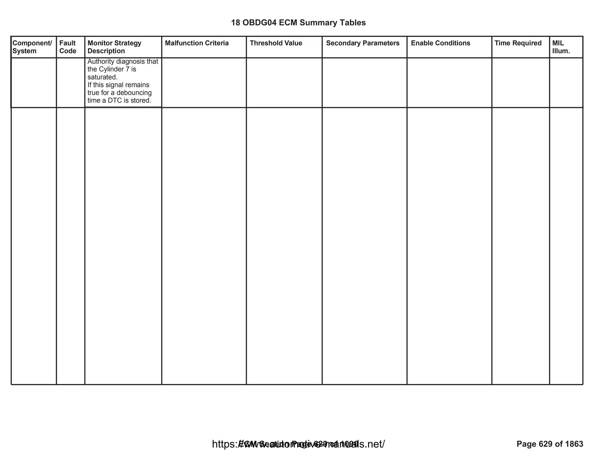
![Component/
System
Fault
Code
Monitor Strategy
Description
Malfunction Criteria Threshold Value Secondary Parameters Enable Conditions Time Required MIL
Illum.
Injector 8
Control
Circuit Low
Voltage (For
8 Cylinder
Engines)
P0282 This DTC detects a
short circuit to ground
of the low side driver
circuit of Injector 8.
Voltage low across low
side drive during off state
indicates short-to-ground
Short to ground:
impedence between
LS pin and controller
ground <= 0.5 [Ohm]
Test enabled by
calibration;
and
Battery voltage
and
Key ON
and
Engine is not cranking
and
Engine Running
and
FUL_OutEnblCyl_CiEPS
R_CylinderD
and
At least one injection
pulse is requested by the
application software
(
FUL_FuelInjectedCyl_CiE
PSR_CylinderD
== [Boolean]
1
> [V]
11.00
-
-
>= [s]
409.59
== 0 [Boolean]
==TRUE);
failures out
10
of samples
20
100 ms/sample
Continuous
Type A,
1 Trips
18 OBDG04 ECM Summary Tables
ECM Section Page 630 of 1090 Page 630 of 1863
https://www.automotive-manuals.net/](https://image.slidesharecdn.com/gmcenginefaultcodesdtc1-230327071418-56d3c5bb/75/18-OBDG04-ECM-Summary-Tables-630-2048.jpg)
![Component/
System
Fault
Code
Monitor Strategy
Description
Malfunction Criteria Threshold Value Secondary Parameters Enable Conditions Time Required MIL
Illum.
Injector 8
Control
Circuit High
Voltage (For
8 Cylinder
Engines)
P0283 This DTC detects a
short circuit to power
supply of the low side
driver circuit of Injector
8.
Voltage high across low
side driver during On
state indicates short to
power
Short to power:
impedence between
LS pin and controller
power <= 0.5 [Ohm]
Test enabled by
calibration;
and
Battery voltage
and
Key ON
and
Engine is not cranking
and
Engine Running
and
FUL_OutEnblCyl_CiEPS
R_CylinderD
and
At least one injection
pulse is requested by the
application software
(
FUL_FuelInjectedCyl_CiE
PSR_CylinderD
== [Boolean]
1
> [V]
11.00
-
-
>= [s]
409.59
== 0 [Boolean]
==TRUE);
10
failures out of
20
samples
100 ms/sample
Continuous
Type A,
1 Trips
18 OBDG04 ECM Summary Tables
ECM Section Page 631 of 1090 Page 631 of 1863
https://www.automotive-manuals.net/](https://image.slidesharecdn.com/gmcenginefaultcodesdtc1-230327071418-56d3c5bb/75/18-OBDG04-ECM-Summary-Tables-631-2048.jpg)
![Component/
System
Fault
Code
Monitor Strategy
Description
Malfunction Criteria Threshold Value Secondary Parameters Enable Conditions Time Required MIL
Illum.
Cylinder
Balance 8
Maximum
Authority
Reached
P0284 The Cylinder Balancing
(CB) strategy is able to
get a cylinder by
cylinder external torque
equalization to improve
engine smooth running
(less engine speed
roughness, more
driving comfort)..
The Cylinder Balancing
uses as input of the
closed loop the
unbalancing signal and
provide, as output, the
fuel volume correction
to apply on each
cylinder. The target of
the closed loop is to get
zero unbalancing on all
cylinders. The
unbalancing signal
cointains the torque
formed during the
combustion phase of
each cylinder.
This diagnosis is able
to detect if Cylinder
Balancing fuel volume
correctionapplied on
cylinder 8 reach the
saturation (positive or
negative) without
achieve the target (zero
unbalancing).
When CB correction for
cylinder 8 reach the
saturation (positive or
negative) the CB
control system sets a
Boolean flag to true in
order to inform the Max
Cylinder Balancing Fuel
Volume Correction on
cylinder 8 saturated
(positive or negative).
FAD_CB_Cyl_C_HiSat
urated
==TRUE
OR
FAD_CB_Cyl_C_LoSat
urated
==TRUE
Test enabled by
calibration
No faults detected on
injectors
Fuel Injector Disable
Device Control not active
CB enabled in closed loop
EOL injector codes written
No errors related to
redundant calculation of
EOL injector codes
No Low fuel tank level
indication
Fuel request higher than a
calibrateable threshold
(OBD Coolant Enable
Criteria
OR
Engine coolant
temperature higher than a
calibrateable threshold)
No faults on Engine
coolant temperature
sensor.
1.00
FUL_GenericInjSysFlt
FUL_InjectorDisable
FAD_CB_CntrlType
==CeFADC_e_CB_CL_E
nbl
FAD_EIA_DID_Written
FAD_EIA_RedntFlt
LowFuelConditionDiagnos
tic
>= [mm3/stroke]
0.00
==TRUE
>= [°C]
0.00
(ECT_Sensor_TFTKO
AND
)
ECT_Sensor_FA
Fail
10.00
Samples over
samples.
20.00
1 sample every
cylinder firing
event.
Type B,
2 Trips
18 OBDG04 ECM Summary Tables
ECM Section Page 632 of 1090 Page 632 of 1863
https://www.automotive-manuals.net/](https://image.slidesharecdn.com/gmcenginefaultcodesdtc1-230327071418-56d3c5bb/75/18-OBDG04-ECM-Summary-Tables-632-2048.jpg)

![Component/
System
Fault
Code
Monitor Strategy
Description
Malfunction Criteria Threshold Value Secondary Parameters Enable Conditions Time Required MIL
Illum.
Cylinder 5
Fuel Injector
Offset
Learning At
Min Limit
P02D4 This diagnosis (Min
Authority monitoring)
performs a check on
the absolute Energizing
Time learnt by SQA
(Small Quantity
Adjustment).
During Diesel Fuel Cut-
off conditions SQA
command the injection
of a known quantity on
one injector (e.g.
1,5mm^3) and checks,
by means of crank-
wheel sensor, the
torque produced during
the combustion phase.
Two different learning
strategies are used:
Target SQA (TSQA):
This strategy is a
closed loop between
fuel quantity injected
and torque produced
during combustion
phase. The fuel
quantity injected is
increased/decreased
until the angular
acceleration target is
reached. The Delta
Energizing Time
needed to achieve the
target is then stored in
SQA Map.
Extrapolated SQA
(ESQA): With this
strategy several
injections with different
injection quantities are
performed and, for
Each time a new value is
entered in SQA map the
diagnosis checks if:
- DeltaET learnt by (x)
SQA on cylinder 4.
The result of this test is
then stored in a boolean
NV array cointaing the
status of Minimum
authority test
(TRUE=Saturated,
FALSE= Not saturated)
for all the rail pressure
levels defined for SQA.
The DTC for minimum
authority reached is set if,
at least one element of
the array is equal to
TRUE and is unset when
all the elements of the
array are equal to FALSE.
<
KaFADC_t_SQA_Min
AdptDeltET[us]
SQA Diagnosis enabled
(x)SQA injection
management enabled
1.00
FAD_SQA_InjMgntEnbld
Time required to
perform a
learning with (x)
SQA.
[Sample Rate: 1
Sample every
cylinder firing
event].
Type B,
2 Trips
18 OBDG04 ECM Summary Tables
ECM Section Page 634 of 1090 Page 634 of 1863
https://www.automotive-manuals.net/](https://image.slidesharecdn.com/gmcenginefaultcodesdtc1-230327071418-56d3c5bb/75/18-OBDG04-ECM-Summary-Tables-634-2048.jpg)


![Component/
System
Fault
Code
Monitor Strategy
Description
Malfunction Criteria Threshold Value Secondary Parameters Enable Conditions Time Required MIL
Illum.
Cylinder 5
Fuel Injector
Offset
Learning At
Max Limit
P02D5 This diagnosis (Max
Authority monitoring)
performs a check on
the absolute Energizing
Time learnt by SQA
(Small Quantity
Adjustment).
During Diesel Fuel Cut-
off conditions SQA
command the injection
of a known quantity on
one injector (e.g.
1,5mm^3) and checks,
by means of crank-
wheel sensor, the
torque produced during
the combustion phase.
Two different learning
strategies are used:
Target SQA (TSQA):
This strategy is a
closed loop between
fuel quantity injected
and torque produced
during combustion
phase. The fuel
quantity injected is
increased/decreased
until the angular
acceleration target is
reached. The Delta
Energizing Time
needed to achieve the
target is then stored in
SQA Map.
Extrapolated SQA
(ESQA): With this
strategy several
injections with different
injection quantities are
performed and, for
Each time a new value is
entered in SQA map the
diagnosis checks if:
- DeltaET learnt by (x)
SQA on cylinder 4
The result of this test is
then stored in a boolean
NV array cointaing the
status of Maximum
authority test
(TRUE=Saturated,
FALSE= Not saturated)
for all the rail pressure
levels defined for SQA.
The DTC for maximum
authority reached is set if,
at least one element of
the array is equal to
TRUE and is unset when
all the elements of the
array are equal to FALSE.
>
KaFADC_t_SQA_Max
AdptDeltET[us]
SQA Diagnosis enabled
(x)SQA injection
management enabled
1.00
FAD_SQA_InjMgntEnbld
Time required to
perform a
learning with (x)
SQA.
[Sample Rate: 1
Sample every
cylinder firing
event].
Type B,
2 Trips
18 OBDG04 ECM Summary Tables
ECM Section Page 637 of 1090 Page 637 of 1863
https://www.automotive-manuals.net/](https://image.slidesharecdn.com/gmcenginefaultcodesdtc1-230327071418-56d3c5bb/75/18-OBDG04-ECM-Summary-Tables-637-2048.jpg)

![Component/
System
Fault
Code
Monitor Strategy
Description
Malfunction Criteria Threshold Value Secondary Parameters Enable Conditions Time Required MIL
Illum.
Cylinder 6
Fuel Injector
Offset
Learning At
Min Limit
P02D6 This diagnosis (Min
Authority monitoring)
performs a check on
the absolute Energizing
Time learnt by SQA
(Small Quantity
Adjustment).
During Diesel Fuel Cut-
off conditions SQA
command the injection
of a known quantity on
one injector (e.g.
1,5mm^3) and checks,
by means of crank-
wheel sensor, the
torque produced during
the combustion phase.
Two different learning
strategies are used:
Target SQA (TSQA):
This strategy is a
closed loop between
fuel quantity injected
and torque produced
during combustion
phase. The fuel
quantity injected is
increased/decreased
until the angular
acceleration target is
reached. The Delta
Energizing Time
needed to achieve the
target is then stored in
SQA Map.
Extrapolated SQA
(ESQA): With this
strategy several
injections with different
injection quantities are
performed and, for
Each time a new value is
entered in SQA map the
diagnosis checks if:
- DeltaET learnt by (x)
SQA on cylinder 4.
The result of this test is
then stored in a boolean
NV array cointaing the
status of Minimum
authority test
(TRUE=Saturated,
FALSE= Not saturated)
for all the rail pressure
levels defined for SQA.
The DTC for minimum
authority reached is set if,
at least one element of
the array is equal to
TRUE and is unset when
all the elements of the
array are equal to FALSE.
<
KaFADC_t_SQA_Min
AdptDeltET[us]
SQA Diagnosis enabled
(x)SQA injection
management enabled
1.00
FAD_SQA_InjMgntEnbld
Time required to
perform a
learning with (x)
SQA.
[Sample Rate: 1
Sample every
cylinder firing
event].
Type B,
2 Trips
18 OBDG04 ECM Summary Tables
ECM Section Page 640 of 1090 Page 640 of 1863
https://www.automotive-manuals.net/](https://image.slidesharecdn.com/gmcenginefaultcodesdtc1-230327071418-56d3c5bb/75/18-OBDG04-ECM-Summary-Tables-640-2048.jpg)


![Component/
System
Fault
Code
Monitor Strategy
Description
Malfunction Criteria Threshold Value Secondary Parameters Enable Conditions Time Required MIL
Illum.
Cylinder 6
Fuel Injector
Offset
Learning At
Max Limit
P02D7 This diagnosis (Max
Authority monitoring)
performs a check on
the absolute Energizing
Time learnt by SQA
(Small Quantity
Adjustment).
During Diesel Fuel Cut-
off conditions SQA
command the injection
of a known quantity on
one injector (e.g.
1,5mm^3) and checks,
by means of crank-
wheel sensor, the
torque produced during
the combustion phase.
Two different learning
strategies are used:
Target SQA (TSQA):
This strategy is a
closed loop between
fuel quantity injected
and torque produced
during combustion
phase. The fuel
quantity injected is
increased/decreased
until the angular
acceleration target is
reached. The Delta
Energizing Time
needed to achieve the
target is then stored in
SQA Map.
Extrapolated SQA
(ESQA): With this
strategy several
injections with different
injection quantities are
performed and, for
Each time a new value is
entered in SQA map the
diagnosis checks if:
- DeltaET learnt by (x)
SQA on cylinder 4
The result of this test is
then stored in a boolean
NV array cointaing the
status of Maximum
authority test
(TRUE=Saturated,
FALSE= Not saturated)
for all the rail pressure
levels defined for SQA.
The DTC for maximum
authority reached is set if,
at least one element of
the array is equal to
TRUE and is unset when
all the elements of the
array are equal to FALSE.
>
KaFADC_t_SQA_Max
AdptDeltET[us]
SQA Diagnosis enabled
(x)SQA injection
management enabled
1.00
FAD_SQA_InjMgntEnbld
Time required to
perform a
learning with (x)
SQA.
[Sample Rate: 1
Sample every
cylinder firing
event].
Type B,
2 Trips
18 OBDG04 ECM Summary Tables
ECM Section Page 643 of 1090 Page 643 of 1863
https://www.automotive-manuals.net/](https://image.slidesharecdn.com/gmcenginefaultcodesdtc1-230327071418-56d3c5bb/75/18-OBDG04-ECM-Summary-Tables-643-2048.jpg)


![Component/
System
Fault
Code
Monitor Strategy
Description
Malfunction Criteria Threshold Value Secondary Parameters Enable Conditions Time Required MIL
Illum.
Cylinder 7
Fuel Injector
Offset
Learning At
Min Limit
P02D8 This diagnosis (Min
Authority monitoring)
performs a check on
the absolute Energizing
Time learnt by SQA
(Small Quantity
Adjustment).
During Diesel Fuel Cut-
off conditions SQA
command the injection
of a known quantity on
one injector (e.g.
1,5mm^3) and checks,
by means of crank-
wheel sensor, the
torque produced during
the combustion phase.
Two different learning
strategies are used:
Target SQA (TSQA):
This strategy is a
closed loop between
fuel quantity injected
and torque produced
during combustion
phase. The fuel
quantity injected is
increased/decreased
until the angular
acceleration target is
reached. The Delta
Energizing Time
needed to achieve the
target is then stored in
SQA Map.
Extrapolated SQA
(ESQA): With this
strategy several
injections with different
injection quantities are
performed and, for
Each time a new value is
entered in SQA map the
diagnosis checks if:
- DeltaET learnt by (x)
SQA on cylinder 4.
The result of this test is
then stored in a boolean
NV array cointaing the
status of Minimum
authority test
(TRUE=Saturated,
FALSE= Not saturated)
for all the rail pressure
levels defined for SQA.
The DTC for minimum
authority reached is set if,
at least one element of
the array is equal to
TRUE and is unset when
all the elements of the
array are equal to FALSE.
<
KaFADC_t_SQA_Min
AdptDeltET[us]
SQA Diagnosis enabled
(x)SQA injection
management enabled
1.00
FAD_SQA_InjMgntEnbld
Time required to
perform a
learning with (x)
SQA.
[Sample Rate: 1
Sample every
cylinder firing
event].
Type B,
2 Trips
18 OBDG04 ECM Summary Tables
ECM Section Page 646 of 1090 Page 646 of 1863
https://www.automotive-manuals.net/](https://image.slidesharecdn.com/gmcenginefaultcodesdtc1-230327071418-56d3c5bb/75/18-OBDG04-ECM-Summary-Tables-646-2048.jpg)


![Component/
System
Fault
Code
Monitor Strategy
Description
Malfunction Criteria Threshold Value Secondary Parameters Enable Conditions Time Required MIL
Illum.
Cylinder 7
Fuel Injector
Offset
Learning At
Max Limit
P02D9 This diagnosis (Max
Authority monitoring)
performs a check on
the absolute Energizing
Time learnt by SQA
(Small Quantity
Adjustment).
During Diesel Fuel Cut-
off conditions SQA
command the injection
of a known quantity on
one injector (e.g.
1,5mm^3) and checks,
by means of crank-
wheel sensor, the
torque produced during
the combustion phase.
Two different learning
strategies are used:
Target SQA (TSQA):
This strategy is a
closed loop between
fuel quantity injected
and torque produced
during combustion
phase. The fuel
quantity injected is
increased/decreased
until the angular
acceleration target is
reached. The Delta
Energizing Time
needed to achieve the
target is then stored in
SQA Map.
Extrapolated SQA
(ESQA): With this
strategy several
injections with different
injection quantities are
performed and, for
Each time a new value is
entered in SQA map the
diagnosis checks if:
- DeltaET learnt by (x)
SQA on cylinder 4
The result of this test is
then stored in a boolean
NV array cointaing the
status of Maximum
authority test
(TRUE=Saturated,
FALSE= Not saturated)
for all the rail pressure
levels defined for SQA.
The DTC for maximum
authority reached is set if,
at least one element of
the array is equal to
TRUE and is unset when
all the elements of the
array are equal to FALSE.
>
KaFADC_t_SQA_Max
AdptDeltET[us]
SQA Diagnosis enabled
(x)SQA injection
management enabled
1.00
FAD_SQA_InjMgntEnbld
Time required to
perform a
learning with (x)
SQA.
[Sample Rate: 1
Sample every
cylinder firing
event].
Type B,
2 Trips
18 OBDG04 ECM Summary Tables
ECM Section Page 649 of 1090 Page 649 of 1863
https://www.automotive-manuals.net/](https://image.slidesharecdn.com/gmcenginefaultcodesdtc1-230327071418-56d3c5bb/75/18-OBDG04-ECM-Summary-Tables-649-2048.jpg)


![Component/
System
Fault
Code
Monitor Strategy
Description
Malfunction Criteria Threshold Value Secondary Parameters Enable Conditions Time Required MIL
Illum.
Cylinder 8
Fuel Injector
Offset
Learning At
Min Limit
P02DA This diagnosis (Min
Authority monitoring)
performs a check on
the absolute Energizing
Time learnt by SQA
(Small Quantity
Adjustment).
During Diesel Fuel Cut-
off conditions SQA
command the injection
of a known quantity on
one injector (e.g.
1,5mm^3) and checks,
by means of crank-
wheel sensor, the
torque produced during
the combustion phase.
Two different learning
strategies are used:
Target SQA (TSQA):
This strategy is a
closed loop between
fuel quantity injected
and torque produced
during combustion
phase. The fuel
quantity injected is
increased/decreased
until the angular
acceleration target is
reached. The Delta
Energizing Time
needed to achieve the
target is then stored in
SQA Map.
Extrapolated SQA
(ESQA): With this
strategy several
injections with different
injection quantities are
performed and, for
Each time a new value is
entered in SQA map the
diagnosis checks if:
- DeltaET learnt by (x)
SQA on cylinder 4.
The result of this test is
then stored in a boolean
NV array cointaing the
status of Minimum
authority test
(TRUE=Saturated,
FALSE= Not saturated)
for all the rail pressure
levels defined for SQA.
The DTC for minimum
authority reached is set if,
at least one element of
the array is equal to
TRUE and is unset when
all the elements of the
array are equal to FALSE.
<
KaFADC_t_SQA_Min
AdptDeltET[us]
SQA Diagnosis enabled
(x)SQA injection
management enabled
1.00
FAD_SQA_InjMgntEnbld
Time required to
perform a
learning with (x)
SQA.
[Sample Rate: 1
Sample every
cylinder firing
event].
Type B,
2 Trips
18 OBDG04 ECM Summary Tables
ECM Section Page 652 of 1090 Page 652 of 1863
https://www.automotive-manuals.net/](https://image.slidesharecdn.com/gmcenginefaultcodesdtc1-230327071418-56d3c5bb/75/18-OBDG04-ECM-Summary-Tables-652-2048.jpg)


![Component/
System
Fault
Code
Monitor Strategy
Description
Malfunction Criteria Threshold Value Secondary Parameters Enable Conditions Time Required MIL
Illum.
Cylinder 8
Fuel Injector
Offset
Learning At
Max Limit
P02DB This diagnosis (Max
Authority monitoring)
performs a check on
the absolute Energizing
Time learnt by SQA
(Small Quantity
Adjustment).
During Diesel Fuel Cut-
off conditions SQA
command the injection
of a known quantity on
one injector (e.g.
1,5mm^3) and checks,
by means of crank-
wheel sensor, the
torque produced during
the combustion phase.
Two different learning
strategies are used:
Target SQA (TSQA):
This strategy is a
closed loop between
fuel quantity injected
and torque produced
during combustion
phase. The fuel
quantity injected is
increased/decreased
until the angular
acceleration target is
reached. The Delta
Energizing Time
needed to achieve the
target is then stored in
SQA Map.
Extrapolated SQA
(ESQA): With this
strategy several
injections with different
injection quantities are
performed and, for
Each time a new value is
entered in SQA map the
diagnosis checks if:
- DeltaET learnt by (x)
SQA on cylinder 4
The result of this test is
then stored in a boolean
NV array cointaing the
status of Maximum
authority test
(TRUE=Saturated,
FALSE= Not saturated)
for all the rail pressure
levels defined for SQA.
The DTC for maximum
authority reached is set if,
at least one element of
the array is equal to
TRUE and is unset when
all the elements of the
array are equal to FALSE.
>
KaFADC_t_SQA_Max
AdptDeltET[us]
SQA Diagnosis enabled
(x)SQA injection
management enabled
1.00
FAD_SQA_InjMgntEnbld
Time required to
perform a
learning with (x)
SQA.
[Sample Rate: 1
Sample every
cylinder firing
event].
Type B,
2 Trips
18 OBDG04 ECM Summary Tables
ECM Section Page 655 of 1090 Page 655 of 1863
https://www.automotive-manuals.net/](https://image.slidesharecdn.com/gmcenginefaultcodesdtc1-230327071418-56d3c5bb/75/18-OBDG04-ECM-Summary-Tables-655-2048.jpg)
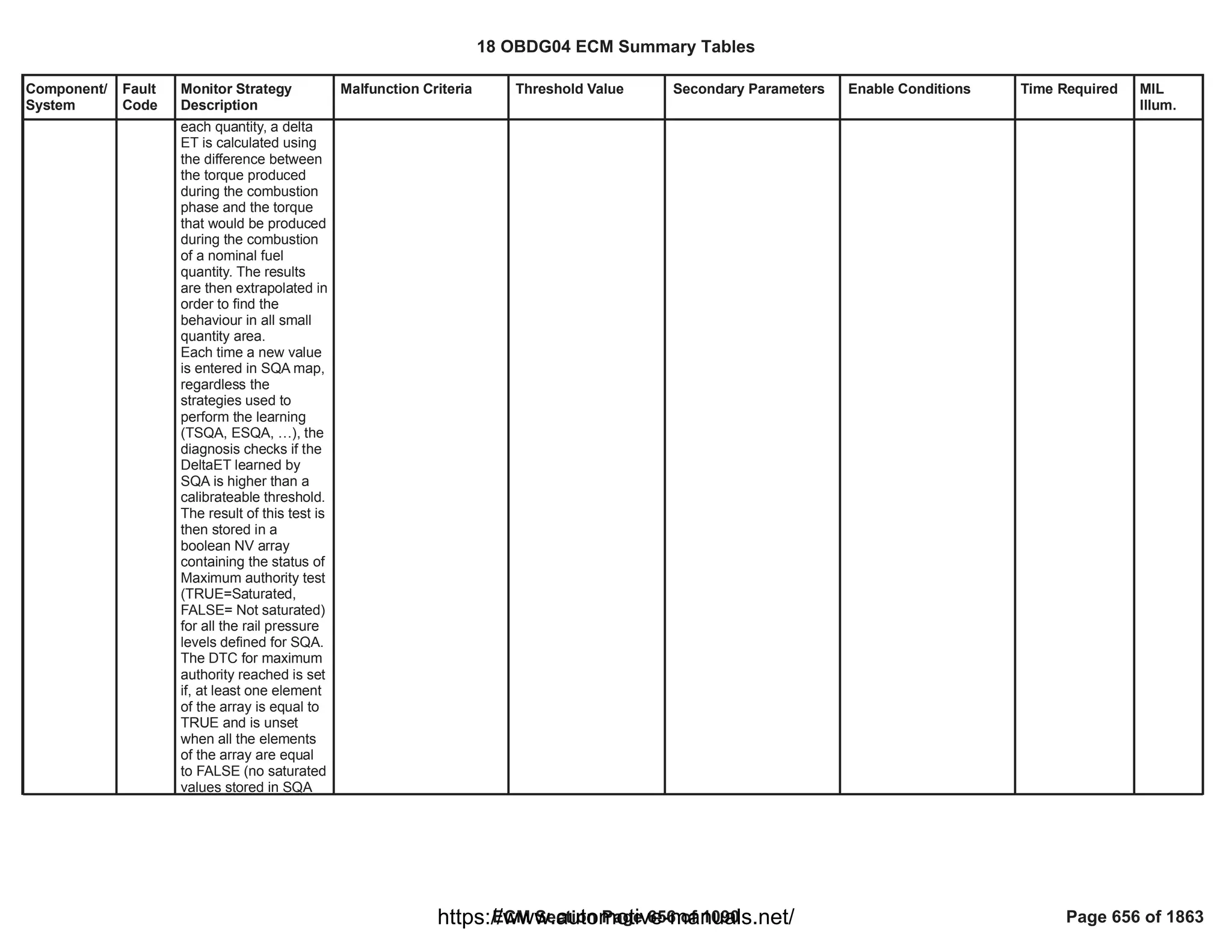

![Component/
System
Fault
Code
Monitor Strategy
Description
Malfunction Criteria Threshold Value Secondary Parameters Enable Conditions Time Required MIL
Illum.
Cylinder 1
Injector
Circuit
Range/
Performance
(For 8
Cylinder
Engines)
P02EE This DTC detects an
Injector fault or ECU
fault that causes
injector 1 End Of
Injection period out of
range
The End Of Injection
period is the time for
the current in the
injector to fall from the
Hold or Bypass current
to zero Ampere
Measurement of the Fall
period of the current pulse
of the injector 1
provided by HWIO
>
[us]
50.00
OR
<
[us]
20.00
Test enabled by
calibration;
and
Battery voltage
and
Key ON
and
No active DTC's:
and
At least one Injection
Pulse is requested by the
application software;
(
FUL_FuelInjectedCyl_CiE
PSR_CylinderA
No information of dropped
pulse reported by HWIO
== [Boolean]
1
> [V]
11.00
-
FUL_InjCktTFTKO
FUL_CntrlrStTFTKO
FUL_BoostVoltTFTKO
FUL_PullInErrTFTKO
== TRUE)
-
failures out
10
of
samples
20
1 sample every
engine cycle
Continuous
Type B,
2 Trips
18 OBDG04 ECM Summary Tables
ECM Section Page 658 of 1090 Page 658 of 1863
https://www.automotive-manuals.net/](https://image.slidesharecdn.com/gmcenginefaultcodesdtc1-230327071418-56d3c5bb/75/18-OBDG04-ECM-Summary-Tables-658-2048.jpg)
![Component/
System
Fault
Code
Monitor Strategy
Description
Malfunction Criteria Threshold Value Secondary Parameters Enable Conditions Time Required MIL
Illum.
Cylinder 2
Injector
Circuit
Range/
Performance
(For 8
Cylinder
Engines)
P02EF This DTC detects an
Injector fault or ECU
fault that causes
injector 2 End Of
Injection period out of
range
The End Of Injection
period is the time for
the current in the
injector to fall from the
Hold or Bypass current
to zero Ampere
Measurement of the Fall
period of the current pulse
of the injector 2
provided by HWIO
>
[us]
50.00
OR
<
[us]
20.00
Test enabled by
calibration;
and
Battery voltage
and
Key ON
and
No active DTC's:
and
At least one Injection
Pulse is requested by the
application software;
(
FUL_FuelInjectedCyl_CiE
PSR_CylinderB
No information of dropped
pulse reported by HWIO
== [Boolean]
1
> [V]
11.00
-
FUL_InjCktTFTKO
FUL_CntrlrStTFTKO
FUL_BoostVoltTFTKO
FUL_PullInErrTFTKO
== TRUE)
-
failures out
10
of
samples
20
1 sample every
engine cycle
Continuous
Type B,
2 Trips
18 OBDG04 ECM Summary Tables
ECM Section Page 659 of 1090 Page 659 of 1863
https://www.automotive-manuals.net/](https://image.slidesharecdn.com/gmcenginefaultcodesdtc1-230327071418-56d3c5bb/75/18-OBDG04-ECM-Summary-Tables-659-2048.jpg)
![Component/
System
Fault
Code
Monitor Strategy
Description
Malfunction Criteria Threshold Value Secondary Parameters Enable Conditions Time Required MIL
Illum.
Cylinder 3
Injector
Circuit
Range/
Performance
(For 8
Cylinder
Engines)
P02F0 This DTC detects an
Injector fault or ECU
fault that causes
injector 3 End Of
Injection period out of
range
The End Of Injection
period is the time for
the current in the
injector to fall from the
Hold or Bypass current
to zero Ampere
Measurement of the Fall
period of the current pulse
of the injector 3
provided by HWIO
>
[us]
50.00
OR
<
[us]
20.00
Test enabled by
calibration;
and
Battery voltage
and
Key ON
and
No active DTC's:
and
At least one Injection
Pulse is requested by the
application software;
(
FUL_FuelInjectedCyl_CiE
PSR_CylinderH
No information of dropped
pulse reported by HWIO
== [Boolean]
1
> [V]
11.00
-
FUL_InjCktTFTKO
FUL_CntrlrStTFTKO
FUL_BoostVoltTFTKO
FUL_PullInErrTFTKO
== TRUE)
-
failures out
10
of
samples
20
1 sample every
engine cycle
Continuous
Type B,
2 Trips
18 OBDG04 ECM Summary Tables
ECM Section Page 660 of 1090 Page 660 of 1863
https://www.automotive-manuals.net/](https://image.slidesharecdn.com/gmcenginefaultcodesdtc1-230327071418-56d3c5bb/75/18-OBDG04-ECM-Summary-Tables-660-2048.jpg)
![Component/
System
Fault
Code
Monitor Strategy
Description
Malfunction Criteria Threshold Value Secondary Parameters Enable Conditions Time Required MIL
Illum.
Cylinder 4
Injector
Circuit
Range/
Performance
(For 8
Cylinder
Engines)
P02F1 This DTC detects an
Injector fault or ECU
fault that causes
injector 4 End Of
Injection period out of
range
The End Of Injection
period is the time for
the current in the
injector to fall from the
Hold or Bypass current
to zero Ampere
Measurement of the Fall
period of the current pulse
of the injector 4
provided by HWIO
>
[us]
50.00
OR
<
[us]
20.00
Test enabled by
calibration;
and
Battery voltage
and
Key ON
and
No active DTC's:
and
At least one Injection
Pulse is requested by the
application software;
(
FUL_FuelInjectedCyl_CiE
PSR_CylinderE
No information of dropped
pulse reported by HWIO
== [Boolean]
1
> [V]
11.00
-
FUL_InjCktTFTKO
FUL_CntrlrStTFTKO
FUL_BoostVoltTFTKO
FUL_PullInErrTFTKO
== TRUE)
-
failures out
10
of
samples
20
1 sample every
engine cycle
Continuous
Type B,
2 Trips
18 OBDG04 ECM Summary Tables
ECM Section Page 661 of 1090 Page 661 of 1863
https://www.automotive-manuals.net/](https://image.slidesharecdn.com/gmcenginefaultcodesdtc1-230327071418-56d3c5bb/75/18-OBDG04-ECM-Summary-Tables-661-2048.jpg)
![Component/
System
Fault
Code
Monitor Strategy
Description
Malfunction Criteria Threshold Value Secondary Parameters Enable Conditions Time Required MIL
Illum.
Cylinder 5
Injector
Circuit
Range/
Performance
(For 8
Cylinder
Engines)
P02F2 This DTC detects an
Injector fault or ECU
fault that causes
injector 5 End Of
Injection period out of
range
The End Of Injection
period is the time for
the current in the
injector to fall from the
Hold or Bypass current
to zero Ampere
Measurement of the Fall
period of the current pulse
of the injector 5
provided by HWIO
>
[us]
50.00
OR
<
[us]
20.00
Test enabled by
calibration;
and
Battery voltage
and
Key ON
and
No active DTC's:
and
At least one Injection
Pulse is requested by the
application software;
(
FUL_FuelInjectedCyl_CiE
PSR_CylinderF
No information of dropped
pulse reported by HWIO
== [Boolean]
1
> [V]
11.00
-
FUL_InjCktTFTKO
FUL_CntrlrStTFTKO
FUL_BoostVoltTFTKO
FUL_PullInErrTFTKO
== TRUE)
-
failures out
10
of
samples
20
1 sample every
engine cycle
Continuous
Type B,
2 Trips
18 OBDG04 ECM Summary Tables
ECM Section Page 662 of 1090 Page 662 of 1863
https://www.automotive-manuals.net/](https://image.slidesharecdn.com/gmcenginefaultcodesdtc1-230327071418-56d3c5bb/75/18-OBDG04-ECM-Summary-Tables-662-2048.jpg)
![Component/
System
Fault
Code
Monitor Strategy
Description
Malfunction Criteria Threshold Value Secondary Parameters Enable Conditions Time Required MIL
Illum.
Cylinder 6
Injector
Circuit
Range/
Performance
(For 8
Cylinder
Engines)
P02F3 This DTC detects an
Injector fault or ECU
fault that causes
injector 6 End Of
Injection period out of
range
The End Of Injection
period is the time for
the current in the
injector to fall from the
Hold or Bypass current
to zero Ampere
Measurement of the Fall
period of the current pulse
of the injector 6
provided by HWIO
>
[us]
50.00
OR
<
[us]
20.00
Test enabled by
calibration;
and
Battery voltage
and
Key ON
and
No active DTC's:
and
At least one Injection
Pulse is requested by the
application software;
(
FUL_FuelInjectedCyl_CiE
PSR_CylinderG
No information of dropped
pulse reported by HWIO
== [Boolean]
1
> [V]
11.00
-
FUL_InjCktTFTKO
FUL_CntrlrStTFTKO
FUL_BoostVoltTFTKO
FUL_PullInErrTFTKO
== TRUE)
-
failures out
10
of
samples
20
1 sample every
engine cycle
Continuous
Type B,
2 Trips
18 OBDG04 ECM Summary Tables
ECM Section Page 663 of 1090 Page 663 of 1863
https://www.automotive-manuals.net/](https://image.slidesharecdn.com/gmcenginefaultcodesdtc1-230327071418-56d3c5bb/75/18-OBDG04-ECM-Summary-Tables-663-2048.jpg)
![Component/
System
Fault
Code
Monitor Strategy
Description
Malfunction Criteria Threshold Value Secondary Parameters Enable Conditions Time Required MIL
Illum.
Cylinder 7
Injector
Circuit
Range/
Performance
(For 8
Cylinder
Engines)
P02F4 This DTC detects an
Injector fault or ECU
fault that causes
injector 7 End Of
Injection period out of
range
The End Of Injection
period is the time for
the current in the
injector to fall from the
Hold or Bypass current
to zero Ampere
Measurement of the Fall
period of the current pulse
of the injector 7
provided by HWIO
>
[us]
50.00
OR
<
[us]
20.00
Test enabled by
calibration;
and
Battery voltage
and
Key ON
and
No active DTC's:
and
At least one Injection
Pulse is requested by the
application software;
(
FUL_FuelInjectedCyl_CiE
PSR_CylinderC
No information of dropped
pulse reported by HWIO
== [Boolean]
1
> [V]
11.00
-
FUL_InjCktTFTKO
FUL_CntrlrStTFTKO
FUL_BoostVoltTFTKO
FUL_PullInErrTFTKO
== TRUE)
-
failures out
10
of
samples
20
1 sample every
engine cycle
Continuous
Type B,
2 Trips
18 OBDG04 ECM Summary Tables
ECM Section Page 664 of 1090 Page 664 of 1863
https://www.automotive-manuals.net/](https://image.slidesharecdn.com/gmcenginefaultcodesdtc1-230327071418-56d3c5bb/75/18-OBDG04-ECM-Summary-Tables-664-2048.jpg)
![Component/
System
Fault
Code
Monitor Strategy
Description
Malfunction Criteria Threshold Value Secondary Parameters Enable Conditions Time Required MIL
Illum.
Cylinder 8
Injector
Circuit
Range/
Performance
(For 8
Cylinder
Engines)
P02F5 This DTC detects an
Injector fault or ECU
fault that causes
injector 8 End Of
Injection period out of
range
The End Of Injection
period is the time for
the current in the
injector to fall from the
Hold or Bypass current
to zero Ampere
Measurement of the Fall
period of the current pulse
of the injector 8
provided by HWIO
>
[us]
50.00
OR
<
[us]
20.00
Test enabled by
calibration;
and
Battery voltage
and
Key ON
and
No active DTC's:
and
At least one Injection
Pulse is requested by the
application software;
(
FUL_FuelInjectedCyl_CiE
PSR_CylinderD
No information of dropped
pulse reported by HWIO
== [Boolean]
1
> [V]
11.00
-
FUL_InjCktTFTKO
FUL_CntrlrStTFTKO
FUL_BoostVoltTFTKO
FUL_PullInErrTFTKO
== TRUE)
-
failures out
10
of
samples
20
1 sample every
engine cycle
Continuous
Type B,
2 Trips
18 OBDG04 ECM Summary Tables
ECM Section Page 665 of 1090 Page 665 of 1863
https://www.automotive-manuals.net/](https://image.slidesharecdn.com/gmcenginefaultcodesdtc1-230327071418-56d3c5bb/75/18-OBDG04-ECM-Summary-Tables-665-2048.jpg)
![Component/
System
Fault
Code
Monitor Strategy
Description
Malfunction Criteria Threshold Value Secondary Parameters Enable Conditions Time Required MIL
Illum.
Injector 1
Positive
Voltage
Control
Circuit
Shorted to
Control
Circuit (For 8
Cylinder
Engines)
P1248 This DTC detects a
shorted load on Injector
1
Voltage high across low
side and High side drivers
during on state indicates
low side shorted to high
side
the time to reach the 2
A threshold of the
injector current is
shorter than 2 us
Test enabled by
calibration;
and
Battery voltage
and
Key ON
and
Engine is not cranking
and
Engine Running
and
FUL_OutEnblCyl_CiEPS
R_CylinderA
and
At least one injection
pulse is requested by the
application software
(
FUL_FuelInjectedCyl_CiE
PSR_CylinderA
== [Boolean]
1
> [V]
11.00
-
-
>= [s]
409.59
== 0 [Boolean]
==TRUE);
failures out
10
of
samples
20
100 ms/sample
Continuous
Type A,
1 Trips
18 OBDG04 ECM Summary Tables
ECM Section Page 666 of 1090 Page 666 of 1863
https://www.automotive-manuals.net/](https://image.slidesharecdn.com/gmcenginefaultcodesdtc1-230327071418-56d3c5bb/75/18-OBDG04-ECM-Summary-Tables-666-2048.jpg)
![Component/
System
Fault
Code
Monitor Strategy
Description
Malfunction Criteria Threshold Value Secondary Parameters Enable Conditions Time Required MIL
Illum.
Injector 2
Positive
Voltage
Control
Circuit
Shorted to
Control
Circuit (For 8
Cylinder
Engines)
P1249 This DTC detects a
shorted load on Injector
2
Voltage high across low
side and High side drivers
during on state indicates
low side shorted to high
side
the time to reach the 2
A threshold of the
injector current is
shorter than 2 us
Test enabled by
calibration;
and
Battery voltage
and
Key ON
and
Engine is not cranking
and
Engine Running
and
FUL_OutEnblCyl_CiEPS
R_CylinderB
and
At least one injection
pulse is requested by the
application software
(
FUL_FuelInjectedCyl_CiE
PSR_CylinderB
== [Boolean]
1
> [V]
11.00
-
-
>= [s]
409.59
== 0 [Boolean]
==TRUE);
failures out
10
of
samples
20
100 ms/sample
Continuous
Type A,
1 Trips
18 OBDG04 ECM Summary Tables
ECM Section Page 667 of 1090 Page 667 of 1863
https://www.automotive-manuals.net/](https://image.slidesharecdn.com/gmcenginefaultcodesdtc1-230327071418-56d3c5bb/75/18-OBDG04-ECM-Summary-Tables-667-2048.jpg)
![Component/
System
Fault
Code
Monitor Strategy
Description
Malfunction Criteria Threshold Value Secondary Parameters Enable Conditions Time Required MIL
Illum.
Injector 3
Positive
Voltage
Control
Circuit
Shorted to
Control
Circuit (For 8
Cylinder
Engines)
P124A This DTC detects a
shorted load on Injector
3
Voltage high across low
side and High side drivers
during on state indicates
low side shorted to high
side
the time to reach the 2
A threshold of the
injector current is
shorter than 2 us
Test enabled by
calibration;
and
Battery voltage
and
Key ON
and
Engine is not cranking
and
Engine Running
and
FUL_OutEnblCyl_CiEPS
R_CylinderH
and
At least one injection
pulse is requested by the
application software
(
FUL_FuelInjectedCyl_CiE
PSR_CylinderH
== [Boolean]
1
> [V]
11.00
-
-
>= [s]
409.59
== 0 [Boolean]
==TRUE);
failures out
10
of
samples
20
100 ms/sample
Continuous
Type A,
1 Trips
18 OBDG04 ECM Summary Tables
ECM Section Page 668 of 1090 Page 668 of 1863
https://www.automotive-manuals.net/](https://image.slidesharecdn.com/gmcenginefaultcodesdtc1-230327071418-56d3c5bb/75/18-OBDG04-ECM-Summary-Tables-668-2048.jpg)
![Component/
System
Fault
Code
Monitor Strategy
Description
Malfunction Criteria Threshold Value Secondary Parameters Enable Conditions Time Required MIL
Illum.
Injector 4
Positive
Voltage
Control
Circuit
Shorted to
Control
Circuit (For 8
Cylinder
Engines)
P124B This DTC detects a
shorted load on Injector
4
Voltage high across low
side and High side drivers
during on state indicates
low side shorted to high
side
the time to reach the 2
A threshold of the
injector current is
shorter than 2 us
Test enabled by
calibration;
and
Battery voltage
and
Key ON
and
Engine is not cranking
and
Engine Running
and
FUL_OutEnblCyl_CiEPS
R_CylinderE
and
At least one injection
pulse is requested by the
application software
(
FUL_FuelInjectedCyl_CiE
PSR_CylinderE
== [Boolean]
1
> [V]
11.00
-
-
>= [s]
409.59
== 0 [Boolean]
==TRUE);
failures out
10
of
samples
20
100 ms/sample
Continuous
Type A,
1 Trips
18 OBDG04 ECM Summary Tables
ECM Section Page 669 of 1090 Page 669 of 1863
https://www.automotive-manuals.net/](https://image.slidesharecdn.com/gmcenginefaultcodesdtc1-230327071418-56d3c5bb/75/18-OBDG04-ECM-Summary-Tables-669-2048.jpg)
![Component/
System
Fault
Code
Monitor Strategy
Description
Malfunction Criteria Threshold Value Secondary Parameters Enable Conditions Time Required MIL
Illum.
Injector 5
Positive
Voltage
Control
Circuit
Shorted to
Control
Circuit (For 8
Cylinder
Engines)
P124C This DTC detects a
shorted load on Injector
5
Voltage high across low
side and High side drivers
during on state indicates
low side shorted to high
side
the time to reach the 2
A threshold of the
injector current is
shorter than 2 us
Test enabled by
calibration;
and
Battery voltage
and
Key ON
and
Engine is not cranking
and
Engine Running
and
FUL_OutEnblCyl_CiEPS
R_CylinderF
and
At least one injection
pulse is requested by the
application software
(
FUL_FuelInjectedCyl_CiE
PSR_CylinderF
== [Boolean]
1
> [V]
11.00
-
-
>= [s]
409.59
== 0 [Boolean]
==TRUE);
failures out
10
of
samples
20
100 ms/sample
Continuous
Type A,
1 Trips
18 OBDG04 ECM Summary Tables
ECM Section Page 670 of 1090 Page 670 of 1863
https://www.automotive-manuals.net/](https://image.slidesharecdn.com/gmcenginefaultcodesdtc1-230327071418-56d3c5bb/75/18-OBDG04-ECM-Summary-Tables-670-2048.jpg)
![Component/
System
Fault
Code
Monitor Strategy
Description
Malfunction Criteria Threshold Value Secondary Parameters Enable Conditions Time Required MIL
Illum.
Injector 6
Positive
Voltage
Control
Circuit
Shorted to
Control
Circuit (For 8
Cylinder
Engines)
P124D This DTC detects a
shorted load on Injector
6
Voltage high across low
side and High side drivers
during on state indicates
low side shorted to high
side
the time to reach the 2
A threshold of the
injector current is
shorter than 2 us
Test enabled by
calibration;
and
Battery voltage
and
Key ON
and
Engine is not cranking
and
Engine Running
and
FUL_OutEnblCyl_CiEPS
R_CylinderG
and
At least one injection
pulse is requested by the
application software
(
FUL_FuelInjectedCyl_CiE
PSR_CylinderG
== [Boolean]
1
> [V]
11.00
-
-
>= [s]
409.59
== 0 [Boolean]
==TRUE);
failures out
10
of
samples
20
100 ms/sample
Continuous
Type A,
1 Trips
18 OBDG04 ECM Summary Tables
ECM Section Page 671 of 1090 Page 671 of 1863
https://www.automotive-manuals.net/](https://image.slidesharecdn.com/gmcenginefaultcodesdtc1-230327071418-56d3c5bb/75/18-OBDG04-ECM-Summary-Tables-671-2048.jpg)
![Component/
System
Fault
Code
Monitor Strategy
Description
Malfunction Criteria Threshold Value Secondary Parameters Enable Conditions Time Required MIL
Illum.
Injector 7
Positive
Voltage
Control
Circuit
Shorted to
Control
Circuit (For 8
Cylinder
Engines)
P124E This DTC detects a
shorted load on Injector
7
Voltage high across low
side and High side drivers
during on state indicates
low side shorted to high
side
the time to reach the 2
A threshold of the
injector current is
shorter than 2 us
Test enabled by
calibration;
and
Battery voltage
and
Key ON
and
Engine is not cranking
and
Engine Running
and
FUL_OutEnblCyl_CiEPS
R_CylinderC
and
At least one injection
pulse is requested by the
application software
(
FUL_FuelInjectedCyl_CiE
PSR_CylinderC
== [Boolean]
1
> [V]
11.00
-
-
>= [s]
409.59
== 0 [Boolean]
==TRUE);
failures out
10
of
samples
20
100 ms/sample
Continuous
Type A,
1 Trips
18 OBDG04 ECM Summary Tables
ECM Section Page 672 of 1090 Page 672 of 1863
https://www.automotive-manuals.net/](https://image.slidesharecdn.com/gmcenginefaultcodesdtc1-230327071418-56d3c5bb/75/18-OBDG04-ECM-Summary-Tables-672-2048.jpg)
![Component/
System
Fault
Code
Monitor Strategy
Description
Malfunction Criteria Threshold Value Secondary Parameters Enable Conditions Time Required MIL
Illum.
Injector 8
Positive
Voltage
Control
Circuit
Shorted to
Control
Circuit (For 8
Cylinder
Engines)
P124F This DTC detects a
shorted load on Injector
8
Voltage high across low
side and High side drivers
during on state indicates
low side shorted to high
side
the time to reach the 2
A threshold of the
injector current is
shorter than 2 us
Test enabled by
calibration;
and
Battery voltage
and
Key ON
and
Engine is not cranking
and
Engine Running
and
FUL_OutEnblCyl_CiEPS
R_CylinderD
and
At least one injection
pulse is requested by the
application software
(
FUL_FuelInjectedCyl_CiE
PSR_CylinderD
== [Boolean]
1
> [V]
11.00
-
-
>= [s]
409.59
== 0 [Boolean]
==TRUE);
failures out
10
of
samples
20
100 ms/sample
Continuous
Type A,
1 Trips
18 OBDG04 ECM Summary Tables
ECM Section Page 673 of 1090 Page 673 of 1863
https://www.automotive-manuals.net/](https://image.slidesharecdn.com/gmcenginefaultcodesdtc1-230327071418-56d3c5bb/75/18-OBDG04-ECM-Summary-Tables-673-2048.jpg)
![Component/
System
Fault
Code
Monitor Strategy
Description
Malfunction Criteria Threshold Value Secondary Parameters Enable Conditions Time Required MIL
Illum.
Exhaust Gas
Recirculation
Cooler
Bypass
Valve
Control
Circuit
Shorted
(ECB DC
Motor)
P1413 This monitor checks if
the HP EGR cooler
bypass valve
commands are shorted
one other
Current flowing through
the H-Bridge switches
higher than a threshold
(error information
provided by HWIO)
> 8 [A] Test enabled by
calibration
System out of the
cranking phase
PT relay supply voltage in
range
H-Bridge driver is ON
Diagnostic system
enabled (no clear code or
EOT in progress)
HWIO error status
different from
INDETERMINATE status
== 1.00
> [V]
11.00
65,535.00
fail counts out of
0.00
sample counts
Function task:
12.5 ms
Type B,
2 Trips
18 OBDG04 ECM Summary Tables
ECM Section Page 674 of 1090 Page 674 of 1863
https://www.automotive-manuals.net/](https://image.slidesharecdn.com/gmcenginefaultcodesdtc1-230327071418-56d3c5bb/75/18-OBDG04-ECM-Summary-Tables-674-2048.jpg)
![Component/
System
Fault
Code
Monitor Strategy
Description
Malfunction Criteria Threshold Value Secondary Parameters Enable Conditions Time Required MIL
Illum.
Exhaust Gas
Recirculation
Cooler
Bypass
Valve
Current
Range/
Performance
(ECB DC
Motor)
P1414 This monitor checks if
an excessive current
flows through the HP
EGR cooler bypass
DC-Motor (e.g. shunt
circuit between load,
HP EGR cooler bypass
DC-Motor internal
faults, etc).
Current flowing through
the H-Bridge higher than
a threshold
(error information
provided by HWIO)
> 6.3 [A] Test enabled by
calibration
System out of the
cranking phase
PT relay supply voltage in
range
No faults present on HP
EGR Cooler Bypass DC
Motor current range/
performance
H-Bridge driver is ON
Diagnostic system
enabled (no clear code or
EOT in progress)
HWIO error status
different from
INDETERMINATE status
== 1.00
> [V]
11.00
CEB_MtrCurrLimTFTKO
== FALSE
65,535.00
fail counts out of
0.00
sample counts
Function task:
12.5 ms
Type B,
2 Trips
18 OBDG04 ECM Summary Tables
ECM Section Page 675 of 1090 Page 675 of 1863
https://www.automotive-manuals.net/](https://image.slidesharecdn.com/gmcenginefaultcodesdtc1-230327071418-56d3c5bb/75/18-OBDG04-ECM-Summary-Tables-675-2048.jpg)
![Component/
System
Fault
Code
Monitor Strategy
Description
Malfunction Criteria Threshold Value Secondary Parameters Enable Conditions Time Required MIL
Illum.
Exhaust Gas
Recirculation
Cooler
Bypass
Valve Supply
Circuit (ECB
DC Motor)
P1438 This monitor checks if
the HP EGR cooler
bypass DC-Motor is
correctly supplied
System voltage supply
lower than a threshold
(error information
provided by HWIO)
< 6 [V] Test enabled by
calibration
System out of the
cranking phase
PT relay supply voltage in
range
Diagnostic system
enabled (no clear code or
EOT in progress)
HWIO error status
different from
INDETERMINATE status
== 1.00
> [V]
11.00
65,535.00
fail counts out of
0.00
sample counts
Function task:
12.5 ms
Type B,
2 Trips
18 OBDG04 ECM Summary Tables
ECM Section Page 676 of 1090 Page 676 of 1863
https://www.automotive-manuals.net/](https://image.slidesharecdn.com/gmcenginefaultcodesdtc1-230327071418-56d3c5bb/75/18-OBDG04-ECM-Summary-Tables-676-2048.jpg)
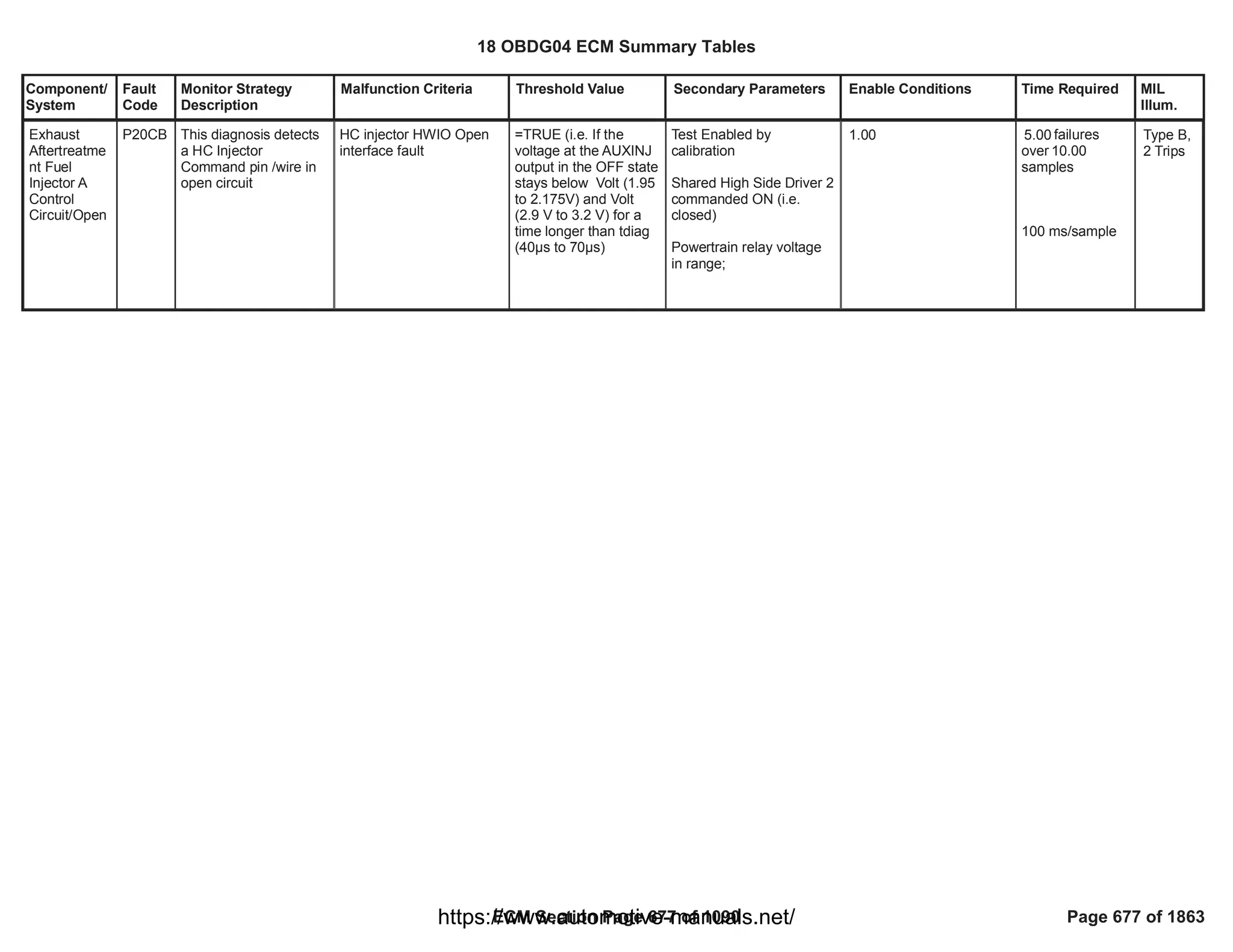
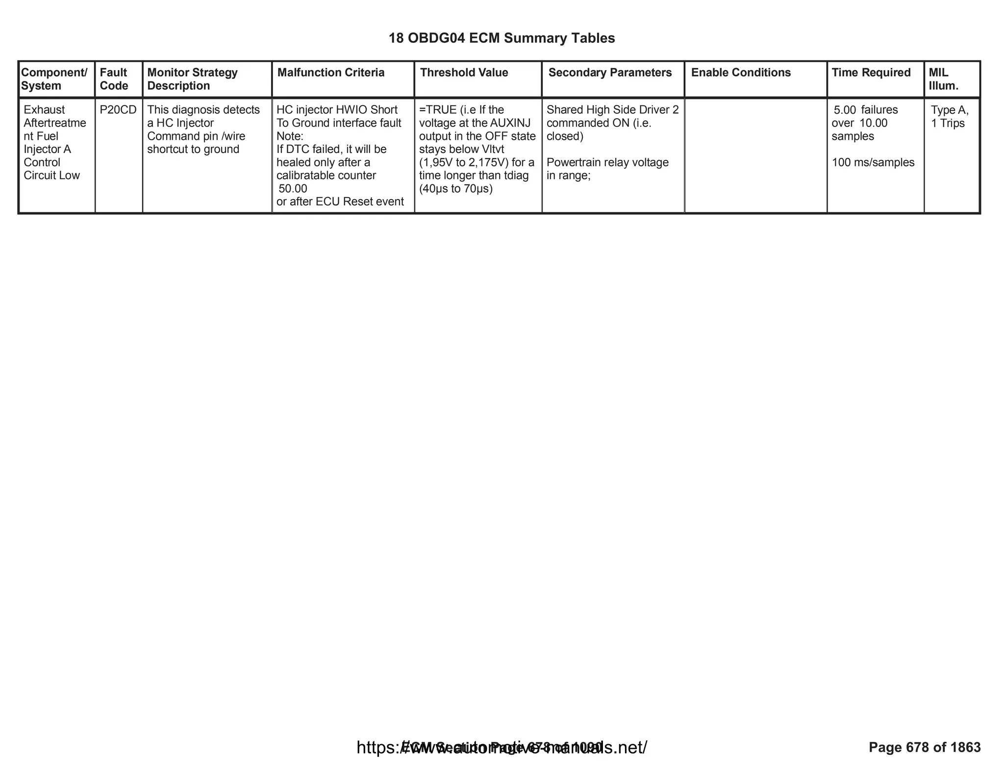
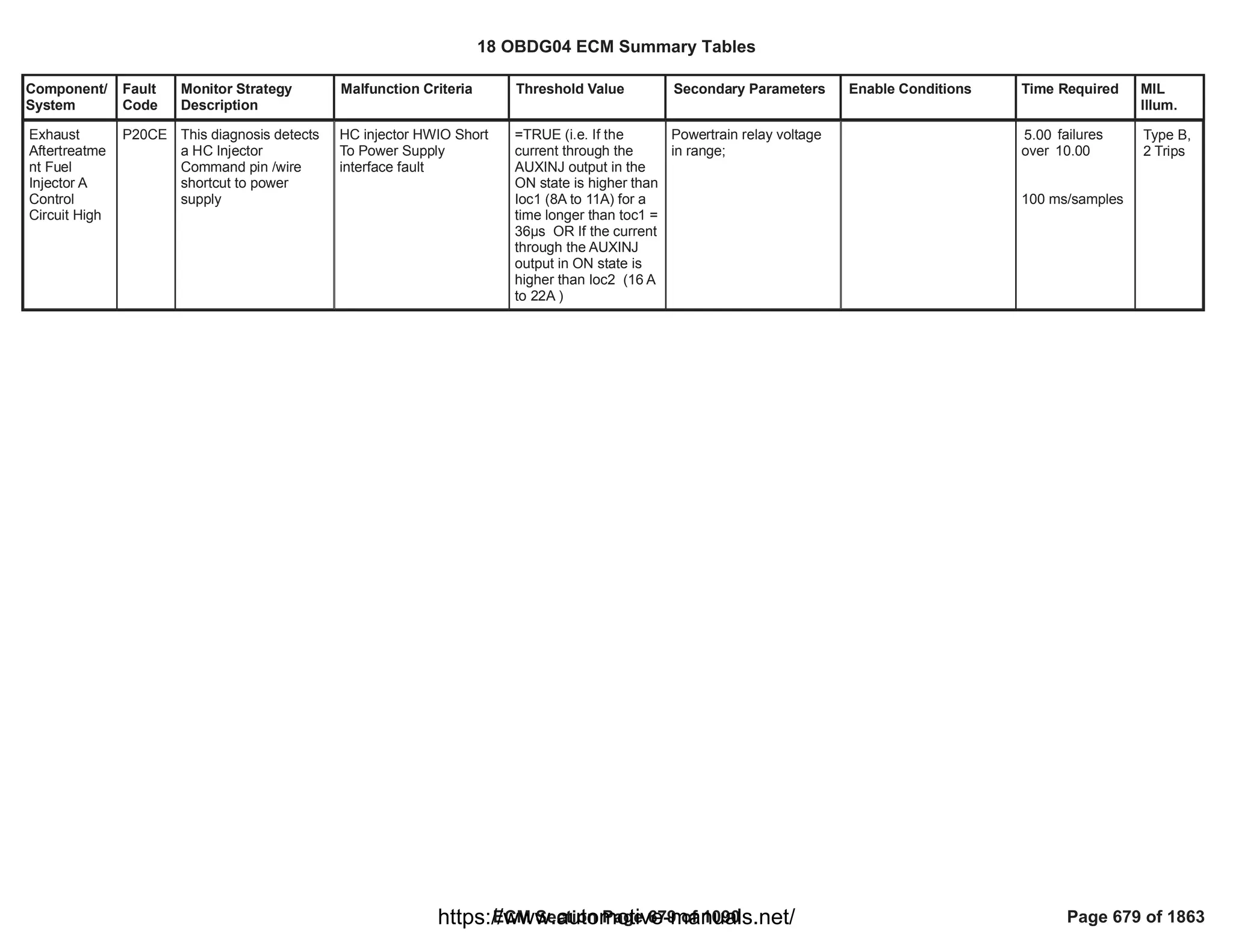
![Component/
System
Fault
Code
Monitor Strategy
Description
Malfunction Criteria Threshold Value Secondary Parameters Enable Conditions Time Required MIL
Illum.
Injector
Positive
Voltage
Control
Circuit
Group 1 Low
Voltage (For
8 Cylinder
Engines)
P2147 This DTC detects a
short circuit to ground
of the high side driver
circuit of the Bank 1
(injector 1 and 4)
Voltage high across High
Side Driver of bank 1
(injector 1 and 4) during
On state indicates short to
ground
impedence between
HS pin of injector 1
and controller ground
<= 0.5 [Ohm]
OR
impedence between
HS pin of injector 4
and controller ground
<= 0.5 [Ohm]
Test enabled by
calibration;
and
Battery voltage
and
Key ON
and
Engine is not cranking
and
Engine Running
and
(
FUL_OutEnblCyl_CiEPS
R_CylinderA
OR
FUL_OutEnblCyl_CiEPS
R_CylinderE
)
and
(
FUL_FuelInjectedCyl_CiE
PSR_CylinderA
OR
FUL_FuelInjectedCyl_CiE
PSR_CylinderE
)
= [Boolean]
1
> [V]
11.00
-
-
>= [s]
409.59
== 0 [Boolean]
== 0 [Boolean]
== TRUE);
== TRUE);
failures out of
5
samples
10
100 ms/sample
Continuous
Type A,
1 Trips
18 OBDG04 ECM Summary Tables
ECM Section Page 680 of 1090 Page 680 of 1863
https://www.automotive-manuals.net/](https://image.slidesharecdn.com/gmcenginefaultcodesdtc1-230327071418-56d3c5bb/75/18-OBDG04-ECM-Summary-Tables-680-2048.jpg)
![Component/
System
Fault
Code
Monitor Strategy
Description
Malfunction Criteria Threshold Value Secondary Parameters Enable Conditions Time Required MIL
Illum.
Injector
Positive
Voltage
Control
Circuit
Group 1
High Voltage
(For 8
Cylinder
Engines)
P2148 This DTC detects a
short circuit to high
voltage of high side
driver circuit of the
Bank 1 (injector 1 and
4)
Voltage low across High
side drive of bank 1
(injector 1 and 4) during
off state indicates short to
power
impedence between
HS pin of injector 1
and controller power
<= 0.5 [Ohm]
OR
impedence between
HS pin of injector 4
and controller power
<= 0.5 [Ohm]
Test enabled by
calibration;
and
Battery voltage
and
Key ON
and
Engine is not cranking
and
Engine Running
and
(
FUL_OutEnblCyl_CiEPS
R_CylinderA
OR
FUL_OutEnblCyl_CiEPS
R_CylinderE
)
and
(
FUL_FuelInjectedCyl_CiE
PSR_CylinderA
OR
FUL_FuelInjectedCyl_CiE
PSR_CylinderE
)
= [Boolean]
1
> [V]
11.00
-
-
>= [s]
409.59
== 0 [Boolean]
== 0 [Boolean]
== TRUE);
== TRUE);
failures out of
5
samples
10
100 ms/sample
Continuous
Type A,
1 Trips
18 OBDG04 ECM Summary Tables
ECM Section Page 681 of 1090 Page 681 of 1863
https://www.automotive-manuals.net/](https://image.slidesharecdn.com/gmcenginefaultcodesdtc1-230327071418-56d3c5bb/75/18-OBDG04-ECM-Summary-Tables-681-2048.jpg)
![Component/
System
Fault
Code
Monitor Strategy
Description
Malfunction Criteria Threshold Value Secondary Parameters Enable Conditions Time Required MIL
Illum.
Injector
Positive
Voltage
Control
Circuit
Group 2 Low
Voltage (For
8 Cylinder
Engines)
P2150 This DTC detects a
short circuit to ground
of the high side driver
circuit of the Bank 2
(injector 2 and 5)
Voltage high across High
Side Driver of bank 2
(injector 2 and 5) during
On state indicates short to
ground
impedence between
HS pin of injector 2
and controller ground
<= 0.5 [Ohm]
OR
impedence between
HS pin of injector 5
and controller ground
<= 0.5 [Ohm]
Test enabled by
calibration;
and
Battery voltage
and
Key ON
and
Engine is not cranking
and
Engine Running
and
(
FUL_OutEnblCyl_CiEPS
R_CylinderB
OR
FUL_OutEnblCyl_CiEPS
R_CylinderF
)
and
(
FUL_FuelInjectedCyl_CiE
PSR_CylinderB
OR
FUL_FuelInjectedCyl_CiE
PSR_CylinderF
)
= [Boolean]
1
> [V]
11.00
-
-
>= [s]
409.59
== 0 [Boolean]
== 0 [Boolean]
== TRUE);
== TRUE);
failures out of
5
samples
10
100 ms/sample
Continuous
Type A,
1 Trips
18 OBDG04 ECM Summary Tables
ECM Section Page 682 of 1090 Page 682 of 1863
https://www.automotive-manuals.net/](https://image.slidesharecdn.com/gmcenginefaultcodesdtc1-230327071418-56d3c5bb/75/18-OBDG04-ECM-Summary-Tables-682-2048.jpg)
![Component/
System
Fault
Code
Monitor Strategy
Description
Malfunction Criteria Threshold Value Secondary Parameters Enable Conditions Time Required MIL
Illum.
Injector
Positive
Voltage
Control
Circuit
Group 2
High Voltage
(For 8
Cylinder
Engines)
P2151 This DTC detects a
short circuit to high
voltage of high side
driver circuit of the
Bank 2 (injector 2 and
5)
Voltage low across High
side drive of bank 2
(injector 2 and 5) during
off state indicates short to
power
impedence between
HS pin of injector 2
and controller power
<= 0.5 [Ohm]
OR
impedence between
HS pin of injector 5
and controller power
<= 0.5 [Ohm]
Test enabled by
calibration;
and
Battery voltage
and
Key ON
and
Engine is not cranking
and
Engine Running
and
(
FUL_OutEnblCyl_CiEPS
R_CylinderB
OR
FUL_OutEnblCyl_CiEPS
R_CylinderF
)
and
(
FUL_FuelInjectedCyl_CiE
PSR_CylinderB
OR
FUL_FuelInjectedCyl_CiE
PSR_CylinderF
)
= [Boolean]
1
> [V]
11.00
-
-
>= [s]
409.59
== 0 [Boolean]
== 0 [Boolean]
== TRUE);
== TRUE);
failures out of
5
samples
10
100 ms/sample
Continuous
Type A,
1 Trips
18 OBDG04 ECM Summary Tables
ECM Section Page 683 of 1090 Page 683 of 1863
https://www.automotive-manuals.net/](https://image.slidesharecdn.com/gmcenginefaultcodesdtc1-230327071418-56d3c5bb/75/18-OBDG04-ECM-Summary-Tables-683-2048.jpg)
![Component/
System
Fault
Code
Monitor Strategy
Description
Malfunction Criteria Threshold Value Secondary Parameters Enable Conditions Time Required MIL
Illum.
Injector
Positive
Voltage
Control
Circuit
Group 3 Low
Voltage (For
8 Cylinder
Engines)
P2153 This DTC detects a
short circuit to ground
of the high side driver
circuit of the Bank 3
(injector 6 and 7)
Voltage high across High
Side Driver of bank 3
(injector 6 and 7) during
On state indicates short to
ground
impedence between
HS pin of injector 6
and controller ground
<= 0.5 [Ohm]
OR
impedence between
HS pin of injector 7
and controller ground
<= 0.5 [Ohm]
Test enabled by
calibration;
and
Battery voltage
and
Key ON
and
Engine is not cranking
and
Engine Running
and
(
FUL_OutEnblCyl_CiEPS
R_CylinderG
OR
FUL_OutEnblCyl_CiEPS
R_CylinderC
)
and
(
FUL_FuelInjectedCyl_CiE
PSR_CylinderG
OR
FUL_FuelInjectedCyl_CiE
PSR_CylinderC
)
= [Boolean]
1
> [V]
11.00
-
-
>= [s]
409.59
== 0 [Boolean]
== 0 [Boolean]
== TRUE);
== TRUE);
failures out of
5
samples
10
100 ms/sample
Continuous
Type A,
1 Trips
18 OBDG04 ECM Summary Tables
ECM Section Page 684 of 1090 Page 684 of 1863
https://www.automotive-manuals.net/](https://image.slidesharecdn.com/gmcenginefaultcodesdtc1-230327071418-56d3c5bb/75/18-OBDG04-ECM-Summary-Tables-684-2048.jpg)
![Component/
System
Fault
Code
Monitor Strategy
Description
Malfunction Criteria Threshold Value Secondary Parameters Enable Conditions Time Required MIL
Illum.
Injector
Positive
Voltage
Control
Circuit
Group 3
High Voltage
(For 8
Cylinder
Engines)
P2154 This DTC detects a
short circuit to high
voltage of high side
driver circuit of the
Bank 3 (injector 6 and
7)
Voltage low across High
side drive of bank 3
(injector 6 and 7) during
off state indicates short to
power
impedence between
HS pin of injector 6
and controller power
<= 0.5 [Ohm]
OR
impedence between
HS pin of injector 7
and controller power
<= 0.5 [Ohm]
Test enabled by
calibration;
and
Battery voltage
and
Key ON
and
Engine is not cranking
and
Engine Running
and
(
FUL_OutEnblCyl_CiEPS
R_CylinderG
OR
FUL_OutEnblCyl_CiEPS
R_CylinderC
)
and
(
FUL_FuelInjectedCyl_CiE
PSR_CylinderG
OR
FUL_FuelInjectedCyl_CiE
PSR_CylinderC
)
= [Boolean]
1
> [V]
11.00
-
-
>= [s]
409.59
== 0 [Boolean]
== 0 [Boolean]
== TRUE);
== TRUE);
failures out of
5
samples
10
100 ms/sample
Continuous
Type A,
1 Trips
18 OBDG04 ECM Summary Tables
ECM Section Page 685 of 1090 Page 685 of 1863
https://www.automotive-manuals.net/](https://image.slidesharecdn.com/gmcenginefaultcodesdtc1-230327071418-56d3c5bb/75/18-OBDG04-ECM-Summary-Tables-685-2048.jpg)
![Component/
System
Fault
Code
Monitor Strategy
Description
Malfunction Criteria Threshold Value Secondary Parameters Enable Conditions Time Required MIL
Illum.
Injector
Positive
Voltage
Control
Circuit
Group 4 Low
Voltage (For
8 Cylinder
Engines)
P2156 This DTC detects a
short circuit to ground
of the high side driver
circuit of the Bank 4
(injector 3 and 8)
Voltage high across High
Side Driver of bank 4
(injector 3 and 8) during
On state indicates short to
ground
impedence between
HS pin of injector 3
and controller ground
<= 0.5 [Ohm]
OR
impedence between
HS pin of injector 8
and controller ground
<= 0.5 [Ohm]
Test enabled by
calibration;
and
Battery voltage
and
Key ON
and
Engine is not cranking
and
Engine Running
and
(
FUL_OutEnblCyl_CiEPS
R_CylinderH
OR
FUL_OutEnblCyl_CiEPS
R_CylinderD
)
and
(
FUL_FuelInjectedCyl_CiE
PSR_CylinderH
OR
FUL_FuelInjectedCyl_CiE
PSR_CylinderD
)
= [Boolean]
1
> [V]
11.00
-
-
>= [s]
409.59
== 0 [Boolean]
== 0 [Boolean]
== TRUE);
== TRUE);
failures out of
5
samples
10
100 ms/sample
Continuous
Type A,
1 Trips
18 OBDG04 ECM Summary Tables
ECM Section Page 686 of 1090 Page 686 of 1863
https://www.automotive-manuals.net/](https://image.slidesharecdn.com/gmcenginefaultcodesdtc1-230327071418-56d3c5bb/75/18-OBDG04-ECM-Summary-Tables-686-2048.jpg)
![Component/
System
Fault
Code
Monitor Strategy
Description
Malfunction Criteria Threshold Value Secondary Parameters Enable Conditions Time Required MIL
Illum.
Injector
Positive
Voltage
Control
Circuit
Group 4
High Voltage
(For 8
Cylinder
Engines)
P2157 This DTC detects a
short circuit to high
voltage of high side
driver circuit of the
Bank 4 (injector 3 and
8)
Voltage low across High
side drive of bank 4
(injector 3 and 8) during
off state indicates short to
power
impedence between
HS pin of injector 3
and controller power
<= 0.5 [Ohm]
OR
impedence between
HS pin of injector 8
and controller power
<= 0.5 [Ohm]
Test enabled by
calibration;
and
Battery voltage
and
Key ON
and
Engine is not cranking
and
Engine Running
and
(
FUL_OutEnblCyl_CiEPS
R_CylinderH
OR
FUL_OutEnblCyl_CiEPS
R_CylinderD
)
and
(
FUL_FuelInjectedCyl_CiE
PSR_CylinderH
OR
FUL_FuelInjectedCyl_CiE
PSR_CylinderD
)
= [Boolean]
1
> [V]
11.00
-
-
>= [s]
409.59
== 0 [Boolean]
== 0 [Boolean]
== TRUE);
== TRUE);
failures out of
5
samples
10
100 ms/sample
Continuous
Type A,
1 Trips
18 OBDG04 ECM Summary Tables
ECM Section Page 687 of 1090 Page 687 of 1863
https://www.automotive-manuals.net/](https://image.slidesharecdn.com/gmcenginefaultcodesdtc1-230327071418-56d3c5bb/75/18-OBDG04-ECM-Summary-Tables-687-2048.jpg)
![Component/
System
Fault
Code
Monitor Strategy
Description
Malfunction Criteria Threshold Value Secondary Parameters Enable Conditions Time Required MIL
Illum.
Particulate
Filter
Deteriorated/
Missing
Substrate
Bank 1
P226D Low Flow Resistance
monitoring detects a
Diesel Particulate Filter
removed or broken or a
Diesel Particulate Filer
pressure sensor pipe
disconnected, clogged,
or blocked
Filtered Flow resistance
( )
DPF_ResistFlowFltd
<
Flow Resistance Too
Low Threshold
Test enabled by
calibration
(TRUE--> enable
FALSE --> disable)
No fault on DPF pressure
sensor (electrical,
rationality and offset)
No fault on upstream DPF
temperature sensor
(electrical and rationality)
No fault on air flow meter
No fault on atmospheric
pressure sensor
DPF status in soot loading
phase (no regeneration
ongoing)
Engine speed
No fault on exhaust mass
flow estimation
Exhaust gas volume flow
greater than a
calibrateable threshold for
more than a calibratable
time
Soot trapped in the DPF
is between two thresholds
1.00
EGP_DiffPresSnsrFlt
( )
EGT_SnsrDPF_UpFlt
OR
MAF_MAF_SnsrFA
MAF_MAF_SnsrTFTKO
=
AmbPresDfltdStatus
CeAAPR_e_AmbPresNot
Dfltd
==
DPF_DPF_St
CeDPFR_e_SootLoading
> [rpm]
500.00
EXF_TotExhDPF_UpFA
> [l/s]
10.00
for > [s]
0.00
[Pct] < Soot <
10.00
[Pct]
100.00
failures
5.00
over 10.00
samples
Function task:
100 ms
Type A,
1 Trips
18 OBDG04 ECM Summary Tables
ECM Section Page 688 of 1090 Page 688 of 1863
https://www.automotive-manuals.net/](https://image.slidesharecdn.com/gmcenginefaultcodesdtc1-230327071418-56d3c5bb/75/18-OBDG04-ECM-Summary-Tables-688-2048.jpg)
![Component/
System
Fault
Code
Monitor Strategy
Description
Malfunction Criteria Threshold Value Secondary Parameters Enable Conditions Time Required MIL
Illum.
Exhaust gas temperature
at DPF inlet is between
two thresholds for a
minimum calibrateable
time
Engine Coolant
Temperature
Ambient Temperature
The distance covered
since last regeneration
Correction of CCB model
The fuel request is
between 2 calibrateable
thresholds for a minimum
calibreable time
[DegC] <
0.00
Temperature < 700.00
[DegC]
for > [s]
0.00
> [DegC]
-256.00
> [DegC]
-7.00
> [km]
0.00
< [%]
0.00
Lo_FR_MontrEnblLoThr
sh
[mm^3] < Fuel <
Lo_FR_MontrEnblHiThr
sh
[mm^3] for > [s]
0.00
18 OBDG04 ECM Summary Tables
ECM Section Page 689 of 1090 Page 689 of 1863
https://www.automotive-manuals.net/](https://image.slidesharecdn.com/gmcenginefaultcodesdtc1-230327071418-56d3c5bb/75/18-OBDG04-ECM-Summary-Tables-689-2048.jpg)
![Component/
System
Fault
Code
Monitor Strategy
Description
Malfunction Criteria Threshold Value Secondary Parameters Enable Conditions Time Required MIL
Illum.
Exhaust Gas
Recirculation
Cooling
System
Performance
(OBDII
market only)
(Duramax
applications)
P2457 This monitor checks
the HP EGR Cooler
efficiency deterioration,
that would cause
vehicle's emissions to
exceed specific
emission levels.
HP EGR Cooler Efficiency
(averaged over a
calibrate-able cumulative
transient time) is
compared with a
threshold.
HP EGR Cooler efficiency
is computed as the ratio
between (HP EGR cooler
upstream temperature -
HP EGR cooler
downstream temperature)
and (HP EGR cooler
upstream temperature -
Engine coolant
temperature).
< [%]
50.00 Calibration on diagnostic
enabling
Diagnostic has not run in
current driving cycle yet
PT Relay voltage in range
Engine is running or
cranking
HP EGR cooler upstream
temperature in range
Ambient Temperature
Ambient pressure
Air Control is Active
Engine Coolant
Temperature
(OR
OBD Coolant Enable
Criteria),
AND
Engine Coolant
Temperature
HP EGR Cooler bypass
==TRUE
1.00
==TRUE
Powertrain relay voltage >
[V]
11.00
==TRUE
> [°C]
350.00
< [°C]
800.00
>= [°C]
-7.00
>= [kPa]
81.30
Refer to "Air Control
Active" Free Form
> [°C]
80.00
==TRUE
< [°C]
95.00
> [s]
3.00
Test executed
after 1,000.00
samples are
collected and
their average is
computed
functional task
100 ms
Type B,
2 Trips
18 OBDG04 ECM Summary Tables
ECM Section Page 690 of 1090 Page 690 of 1863
https://www.automotive-manuals.net/](https://image.slidesharecdn.com/gmcenginefaultcodesdtc1-230327071418-56d3c5bb/75/18-OBDG04-ECM-Summary-Tables-690-2048.jpg)
![Component/
System
Fault
Code
Monitor Strategy
Description
Malfunction Criteria Threshold Value Secondary Parameters Enable Conditions Time Required MIL
Illum.
not active for a time
HP EGR flow in range
for a time
HP EGR flow estimation is
valid
Engine speed in range
No fault on HP EGR
cooler upstream
temperature sensor
No fault on HP EGR
cooler downstream
temperature sensor
No fault on Ambient
Temperature sensor
No fault on ambient
pressure sensor
No fault on engine coolant
temperature sensor
No fault on engine speed
< [mg/s]
20.00
> [mg/s]
10.00
>= [s]
1.00
EGR_VlvTotFlowNotValid
==FALSE
< [rpm]
2,000.00
> [rpm]
1,200.00
==FALSE
CET_UPSS_FA
==FALSE
CET_DNSS_FA
OAT_PtEstFiltFA
==FALSE
AAP_AmbientAirPresDfltd
==FALSE
ECT_Sensor_FA
==FALSE
CrankSensor_FA
==FALSE
18 OBDG04 ECM Summary Tables
ECM Section Page 691 of 1090 Page 691 of 1863
https://www.automotive-manuals.net/](https://image.slidesharecdn.com/gmcenginefaultcodesdtc1-230327071418-56d3c5bb/75/18-OBDG04-ECM-Summary-Tables-691-2048.jpg)

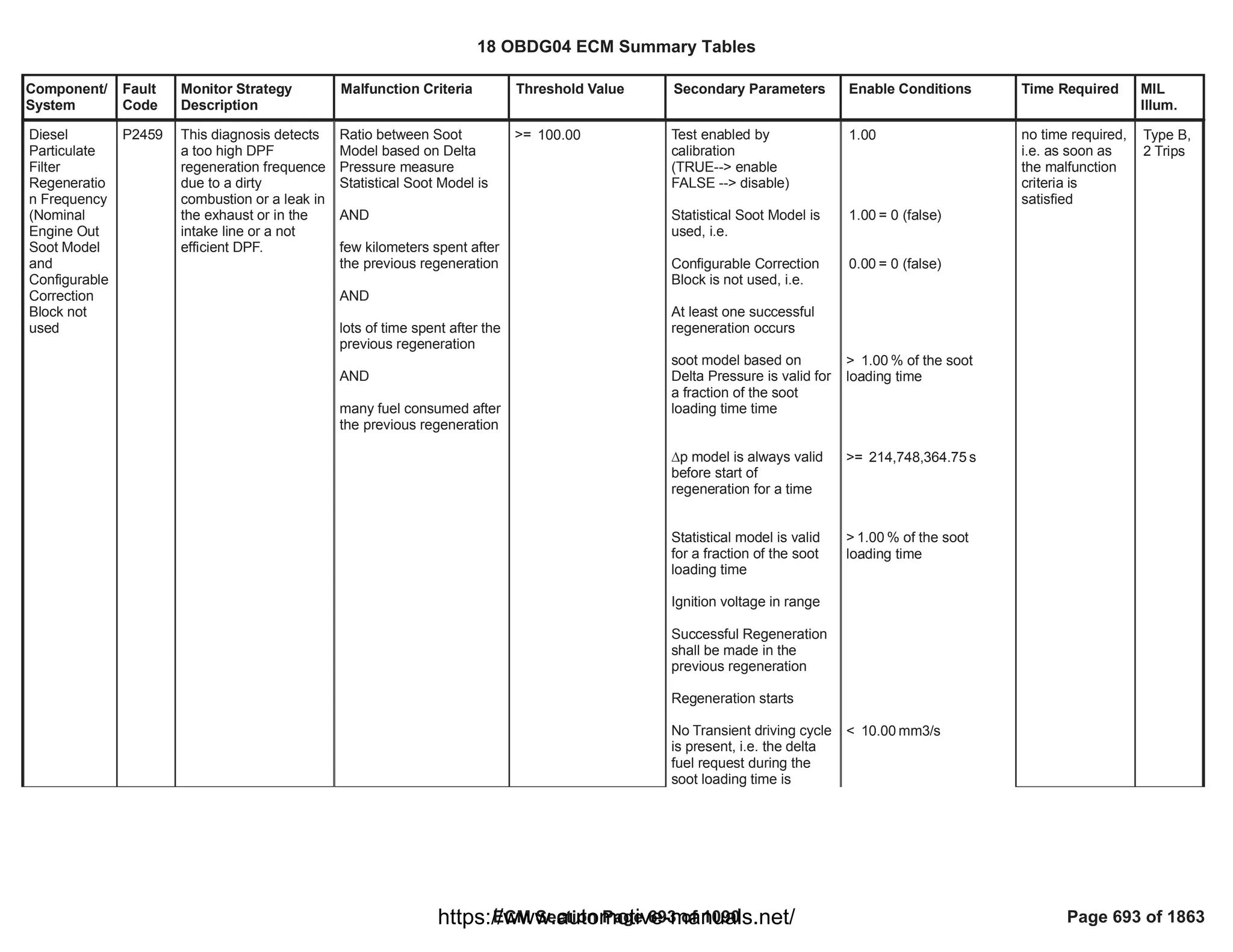
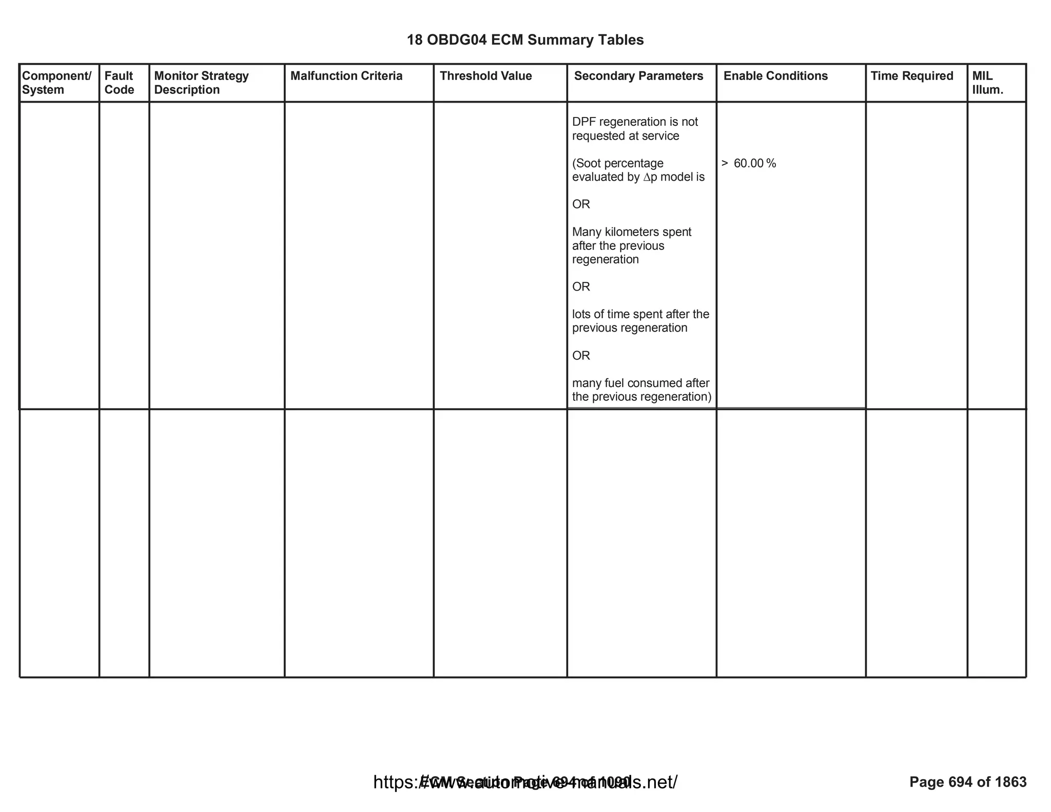
![Component/
System
Fault
Code
Monitor Strategy
Description
Malfunction Criteria Threshold Value Secondary Parameters Enable Conditions Time Required MIL
Illum.
Exhaust Gas
Recirculation
Cooler
Bypass
Valve
Control
Circuit (ECB
DC Motor)
P245A This monitor checks if
the HP EGR cooler
bypass valve
commands are in open
circuit
Load resistance higher
than a threshold (error
information provided by
HWIO)
> 200 [kOhm] Test enabled by
calibration
System out of the
cranking phase
PT relay supply voltage in
range
H-Bridge driver is OFF
Valve requested in a
position different from fully
closed (default position)
Diagnostic system
enabled (no clear code or
EOT in progress)
HWIO error status
different from
INDETERMINATE status
== 1.00
> [V]
11.00
65,535.00
fail counts out of
0.00
sample counts
Function task:
12.5 ms
Type B,
2 Trips
18 OBDG04 ECM Summary Tables
ECM Section Page 695 of 1090 Page 695 of 1863
https://www.automotive-manuals.net/](https://image.slidesharecdn.com/gmcenginefaultcodesdtc1-230327071418-56d3c5bb/75/18-OBDG04-ECM-Summary-Tables-695-2048.jpg)
![Component/
System
Fault
Code
Monitor Strategy
Description
Malfunction Criteria Threshold Value Secondary Parameters Enable Conditions Time Required MIL
Illum.
Exhaust Gas
Recirculation
Cooler
Bypass
Valve
Performance
(ECB DC
Motor)
P245B This monitor detects an
obstruction on the
actuator (obstruction
found during the HP
EGR Cooler Bypass
valve opening or
closing) checking the
setpoint position
against the position
measured by the HP
EGR Cooler Bypass
Position Sensor
|HP EGR Cooler Bypass
Position Tracking Error|
(setpoint position -
measured position) >
maximum threshold
> [%]
0.00 Test enabled by
calibration
Diagnostic system
enabled (no clear code or
EOT in progress)
System out of the
cranking phase
PT relay supply voltage in
range
HP EGR Cooler Bypass
position closed loop
control active (no faults
present on
HP EGR Cooler Bypass
position sensor, HP EGR
Cooler Bypass flap, HP
EGR Cooler Bypass
position control deviation)
HP EGR Cooler Bypass
position setpoint in steady
state conditions for
minimum time
Engine coolant
temperature higher or
equal to minimum
threshold
OR
Engine cooling system
== 1.00
> [V]
11.00
CEB_PstnSnsrFlt
==FALSE
==FALSE
CEB_ActrFlt
CEB_ObstructionTFTKO
==FALSE
< [%/s]
100.00
> [%/s]
-100.00
for >= [s]
0.00
>= [°C]
0.00
65,535.00
fail counts out of
0.00
sample counts
fail
65,535.00
counts to enable
the open circuit
check (P245A)
Function task:
6.25 ms
Type B,
2 Trips
18 OBDG04 ECM Summary Tables
ECM Section Page 696 of 1090 Page 696 of 1863
https://www.automotive-manuals.net/](https://image.slidesharecdn.com/gmcenginefaultcodesdtc1-230327071418-56d3c5bb/75/18-OBDG04-ECM-Summary-Tables-696-2048.jpg)
![Component/
System
Fault
Code
Monitor Strategy
Description
Malfunction Criteria Threshold Value Secondary Parameters Enable Conditions Time Required MIL
Illum.
target temperature
reached (thermostat
opening)
No faults present on
engine coolant
temperature sensor
Outside air temperature
higher or equal to
minimum threshold
No faults present on
outside air temperature
sensor
No mechanical stop soft
approach in progress
No anti-sticking procedure
in progress
ECT_Sensor_FA
==FALSE
>= [°C]
0.00
OAT_PtEstFiltFA
==FALSE
18 OBDG04 ECM Summary Tables
ECM Section Page 697 of 1090 Page 697 of 1863
https://www.automotive-manuals.net/](https://image.slidesharecdn.com/gmcenginefaultcodesdtc1-230327071418-56d3c5bb/75/18-OBDG04-ECM-Summary-Tables-697-2048.jpg)
![Component/
System
Fault
Code
Monitor Strategy
Description
Malfunction Criteria Threshold Value Secondary Parameters Enable Conditions Time Required MIL
Illum.
Exhaust Gas
Recirculation
Cooler
Bypass
Valve
Position
Sensor
Circuit Low
(analog
position
sensor)
P2494 This monitor checks if
the HP EGR cooler
bypass position analog
sensor is out of
electrical range low
analog position raw
voltage < low threshold
< [%5V]
0.00 Test enabled by
calibration
System out of the
cranking phase
PT relay supply voltage in
range
= 1.00
> [V]
11.00
255.00
fail counts out of
0.00
sample counts
Function task:
6.25 ms
Type B,
2 Trips
18 OBDG04 ECM Summary Tables
ECM Section Page 698 of 1090 Page 698 of 1863
https://www.automotive-manuals.net/](https://image.slidesharecdn.com/gmcenginefaultcodesdtc1-230327071418-56d3c5bb/75/18-OBDG04-ECM-Summary-Tables-698-2048.jpg)
![Component/
System
Fault
Code
Monitor Strategy
Description
Malfunction Criteria Threshold Value Secondary Parameters Enable Conditions Time Required MIL
Illum.
Exhaust Gas
Recirculation
Cooler
Bypass
Valve
Position
Sensor
Circuit High
(analog
position
sensor)
P2495 This monitor checks if
the HP EGR cooler
bypass position analog
sensor is out of
electrical range high
analog position raw
voltage > high threshold
> [%5V]
100.00 Test enabled by
calibration
System out of the
cranking phase
PT relay supply voltage in
range
= 1.00
> [V]
11.00
255.00
fail counts out of
0.00
sample counts
Function task:
6.25 ms
Type B,
2 Trips
18 OBDG04 ECM Summary Tables
ECM Section Page 699 of 1090 Page 699 of 1863
https://www.automotive-manuals.net/](https://image.slidesharecdn.com/gmcenginefaultcodesdtc1-230327071418-56d3c5bb/75/18-OBDG04-ECM-Summary-Tables-699-2048.jpg)
![Component/
System
Fault
Code
Monitor Strategy
Description
Malfunction Criteria Threshold Value Secondary Parameters Enable Conditions Time Required MIL
Illum.
Diesel
Particulate
Filter
Restriction -
Ash
Accumulatio
n
P24A4 This diagnostic detects
a clogged DPF that has
to be replaced
Soot model based on
Delta pressure measure
plus configurable
correction block (CCB)
Filtered flow resistance
( )
DPF_ResistFlowFltd
> 1,000.00 Test enabled by
calibration
(TRUE--> enable
FALSE --> disable)
No fault on DPF pressure
sensor (electrical,
rationality and offset)
No fault on upstream DPF
temperature sensor
(electrical and rationality)
No fault on air flow meter
No fault on atmospheric
pressure sensor
DPF status in soot loading
phase (no regeneration
ongoing)
Engine speed
No fault on exhaust mass
flow estimation
Exhaust gas volume flow
greater than a
calibrateable threshold for
more than a calibratable
time
Exhaust gas temperature
at DPF inlet is between
two thresholds for a
minimum calibrateable
1.00
EGP_DiffPresSnsrFlt
EGT_SnsrDPF_UpFlt
OR
MAF_MAF_SnsrFA
MAF_MAF_SnsrTFTKO
=
AmbPresDfltdStatus
CeAAPR_e_AmbPresNot
Dfltd
==
DPF_DPF_St
CeDPFR_e_SootLoading
> [rpm]
500.00
EXF_TotExhDPF_UpFA
> [l/s]
0.00
for > [s]
0.00
[DegC] <
0.00
Temperature < 1,000.00
[DegC]
failures
5.00
over 10.00
samples
function task:
100 ms
Type A,
1 Trips
18 OBDG04 ECM Summary Tables
ECM Section Page 700 of 1090 Page 700 of 1863
https://www.automotive-manuals.net/](https://image.slidesharecdn.com/gmcenginefaultcodesdtc1-230327071418-56d3c5bb/75/18-OBDG04-ECM-Summary-Tables-700-2048.jpg)
![Component/
System
Fault
Code
Monitor Strategy
Description
Malfunction Criteria Threshold Value Secondary Parameters Enable Conditions Time Required MIL
Illum.
time
Engine Coolant
Temperature
Ambient Temperature
Soot model based on
Delta Pressure plus
configurable correction
block (CCB) is valid for a
time
Soot model based on
Delta Pressure is always
valid for a time
Distance since last
completed regeneration
for > [s]
0.00
> [DegC]
0.00
> [DegC]
100.00
> = % of the soot
2.00
loading
>= s
1,000,000.00
> km
100,000.00
18 OBDG04 ECM Summary Tables
ECM Section Page 701 of 1090 Page 701 of 1863
https://www.automotive-manuals.net/](https://image.slidesharecdn.com/gmcenginefaultcodesdtc1-230327071418-56d3c5bb/75/18-OBDG04-ECM-Summary-Tables-701-2048.jpg)
![Component/
System
Fault
Code
Monitor Strategy
Description
Malfunction Criteria Threshold Value Secondary Parameters Enable Conditions Time Required MIL
Illum.
Exhaust Gas
Recirculation
Cooler
Bypass
Valve
Control
Stuck (ECB
DC Motor)
P24A5 This monitor detects
the HP EGR Cooler
Bypass mechanically
stuck in a certain
position different from
its defaulted position
(fully closed, cooling
mode) when the
actuator is no longer
driven (missing
dafaulted position)
Measured HP EGR
Cooler Bypass position >
maximum threshold (not
cooling position)
> [%]
0.00 P245B is already set
Waiting time after driver
shut off > minimum
threshold (needed for the
spring to drive the vanes
in their defaulted position)
Diagnostic system
enabled (no clear code or
EOT in progress)
HP EGR Cooler Bypass
position closed loop
control active (no faults
present on
HP EGR Cooler Bypass
position sensor, HP EGR
Cooler Bypass flap, HP
EGR Cooler Bypass
position control deviation)
> [s]
0.00
CEB_PstnSnsrFlt
==FALSE
==FALSE
CEB_ActrFlt
CEB_ObstructionTFTKO
==FALSE
No debounce is
present: DTC
sets as soon as
the error is
present
Function task:
6.25 ms
Type B,
2 Trips
18 OBDG04 ECM Summary Tables
ECM Section Page 702 of 1090 Page 702 of 1863
https://www.automotive-manuals.net/](https://image.slidesharecdn.com/gmcenginefaultcodesdtc1-230327071418-56d3c5bb/75/18-OBDG04-ECM-Summary-Tables-702-2048.jpg)
![Component/
System
Fault
Code
Monitor Strategy
Description
Malfunction Criteria Threshold Value Secondary Parameters Enable Conditions Time Required MIL
Illum.
Exhaust Gas
Recirculation
Cooler
Bypass
Valve
Position
Sensor
Exceeded
Learning
Limit (analog
position
sensor)
P24C4 This monitor checks if
the HP EGR cooler
bypass position analog
sensor has an offset
with respect to the
nominal position where
the valve does the
learning procedure
(cooling position and
bypass position)
analog position raw
voltage when the valve is
in cooling position <
low threshold
OR
analog position raw
voltage when the valve is
in cooling position >
high threshold
OR
analog position raw
voltage when the valve is
in bypass position <
low threshold
OR
analog position raw
voltage when the valve is
in bypass position >
high threshold
< [%5V]
0.00
OR
> [%5V]
0.00
OR
< [%5V]
0.00
OR
> [%5V]
0.00
Test enabled by
calibration
Learning procedure at key
off in fully closed and fully
open position has been
successfully completed:
- engine coolant in range;
- no faults present on
engine coolant
temperature.
No faults present on HP
EGR cooler bypass
position sensor, HP EGR
cooler bypass valve, HP
EGR cooler bypass
position deviation
End Of Trip event has
elapsed
= 1.00
>= [°C]
0.00
<= [°C]
0.00
==
ECT_Sensor_FA
FALSE
== FALSE
CEB_ActrFlt
==
CEB_PstnSnsrFlt
FALSE
CEB_ObstructionTFTKO
== FALSE
No debounce is
present: DTC
sets as soon as
the error is
present
Function task:
at key off
Type B,
2 Trips
18 OBDG04 ECM Summary Tables
ECM Section Page 703 of 1090 Page 703 of 1863
https://www.automotive-manuals.net/](https://image.slidesharecdn.com/gmcenginefaultcodesdtc1-230327071418-56d3c5bb/75/18-OBDG04-ECM-Summary-Tables-703-2048.jpg)
![Component/
System
Fault
Code
Monitor Strategy
Description
Malfunction Criteria Threshold Value Secondary Parameters Enable Conditions Time Required MIL
Illum.
Exhaust Gas
Recirculation
Cooler
Bypass
Valve Motor
Overtempera
ture (ECB
DC Motor)
P2AA5 This monitor checks if
the temperature of the
HP EGR cooler bypass
DC-Motor increases
too much (e.g. HP EGR
cooler bypass DC-
Motor internal faults,
etc).
H-Bridge driver
temperature higher than a
threshold
(error information
provided by HWIO)
> 170 [°C] Test enabled by
calibration
System out of the
cranking phase
PT relay supply voltage in
range
Diagnostic system
enabled (no clear code or
EOT in progress)
HWIO error status
different from
INDETERMINATE status
== 1.00
> [V]
11.00
65,535.00
fail counts out of
0.00
sample counts
Function task:
12.5 ms
Type B,
2 Trips
18 OBDG04 ECM Summary Tables
ECM Section Page 704 of 1090 Page 704 of 1863
https://www.automotive-manuals.net/](https://image.slidesharecdn.com/gmcenginefaultcodesdtc1-230327071418-56d3c5bb/75/18-OBDG04-ECM-Summary-Tables-704-2048.jpg)
![Component/
System
Fault
Code
Monitor Strategy
Description
Malfunction Criteria Threshold Value Secondary Parameters Enable Conditions Time Required MIL
Illum.
Turbocharge
r VGT A
Position
Exceeded
Learning
Limit (VGT
Vacuum)
P003A This monitor checks if
the VGT position
analog sensor has an
offset with respect to
the nominal positions
where the valve does
the learning procedure
(fully closed and/or fully
open)
analog position raw
voltage when the valve is
in fully closed position <
low threshold
OR
analog position raw
voltage when the valve is
in fully closed position >
high threshold
OR
analog position raw
voltage when the valve is
in wide open position <
low threshold
OR
analog position raw
voltage when the valve is
in wide open position >
high threshold
< [%5V]
75.40
OR
> [%5V]
85.40
OR
< [%5V]
15.00
OR
> [%5V]
33.70
Test enabled by
calibration
Key signal is off
Learning procedure at key
off in fully closed and/or
wide open positions have
been successfully
completed:
-engine coolant
temperature in range;
-ambient pressure in
range;
-battery voltage in range;
- engine idle speed in
range;
- no faults present on
coolant temperature
sensor.
No faults present on VGT
position sensor, VGT
valve, VGTposition
deviation.
Break pedal not pushed
End Of Trip event has
== 1.00
>= (°C)
60.00
<= (°C)
150.00
>= (Pa)
60.00
<= (Pa)
103.00
>= (V)
11.00
<= (V)
32.00
>= (rpm)
700.00
<= (rpm)
950.00
ECT_Sensor_FA
==FALSE
VGT_PstnSnsrFA
==FALSE
==FALSE
VGT_ActCktFA
VGT_PstnCntrlFA
==FALSE
No debounce is
present: DTC
sets as soon as
the error is
present
Function task:
at key off
Type A,
1 Trips
18 OBDG04 ECM Summary Tables
ECM Section Page 705 of 1090 Page 705 of 1863
https://www.automotive-manuals.net/](https://image.slidesharecdn.com/gmcenginefaultcodesdtc1-230327071418-56d3c5bb/75/18-OBDG04-ECM-Summary-Tables-705-2048.jpg)
![Component/
System
Fault
Code
Monitor Strategy
Description
Malfunction Criteria Threshold Value Secondary Parameters Enable Conditions Time Required MIL
Illum.
Turbocharge
r VGT A
Control
Circuit (VGT
Vacuum)
P0045 This monitor checks if
the vacuum VGT
command is in open
circuit
Load resistance higher
than a threshold (error
information provided by
HWIO)
> 200 [kOhm] Test enabled by
calibration
System out of the
cranking phase
Run Crank relay supply
voltage in range
Vanes are requested in a
position different from fully
open (defaulted position)
Shared High Side driver
driven closed
Diagnostic system
enabled (no clear code or
EOT in progress)
HWIO error status
different from
INDETERMINATE status
== 0.00
> [V]
11.00
24.00
fail counts out of
30.00
sample counts
Function task:
100 ms
Type A,
1 Trips
18 OBDG04 ECM Summary Tables
ECM Section Page 707 of 1090 Page 707 of 1863
https://www.automotive-manuals.net/](https://image.slidesharecdn.com/gmcenginefaultcodesdtc1-230327071418-56d3c5bb/75/18-OBDG04-ECM-Summary-Tables-707-2048.jpg)
![Component/
System
Fault
Code
Monitor Strategy
Description
Malfunction Criteria Threshold Value Secondary Parameters Enable Conditions Time Required MIL
Illum.
Turbocharge
r VGT A
Performance
(VGT
Vacuum)
P0046 This monitor detects an
obstruction on the
actuator (obstruction
found during the vanes
opening or closing)
checking the setpoint
position against the
position measured by
the VGT Position
Sensor
|VGT Position Tracking
Error| (setpoint position -
measured position) >
maximum threshold
> [%]
15.00 Test enabled by
calibration
Diagnostic system
enabled (no clear code or
EOT in progress)
System out of the
cranking phase
Run Crank relay supply
voltage in range
VGT position closed loop
control active (no faults
present on
VGT position sensor, VGT
vanes, VGT position
control deviation)
VGT position setpoint in
steady state conditions for
minimum time
Engine coolant
temperature higher or
equal to minimum
threshold
OR
Engine cooling system
target temperature
reached (thermostat
opening)
== 1.00
> [V]
11.00
VGT_PstnSnsrFA
==FALSE
==FALSE
VGT_ActCktFA
VGT_PstnCntrlFA
==FALSE
> [%/s]
-30.00
< [%/s]
30.00
for >= [s]
1.00
>= [°C]
60.00
640.00
fail counts out of
800.00
sample counts
Function task:
6.25 ms
Type A,
1 Trips
18 OBDG04 ECM Summary Tables
ECM Section Page 708 of 1090 Page 708 of 1863
https://www.automotive-manuals.net/](https://image.slidesharecdn.com/gmcenginefaultcodesdtc1-230327071418-56d3c5bb/75/18-OBDG04-ECM-Summary-Tables-708-2048.jpg)
![Component/
System
Fault
Code
Monitor Strategy
Description
Malfunction Criteria Threshold Value Secondary Parameters Enable Conditions Time Required MIL
Illum.
No faults present on
engine coolant
temperature sensor
Outside air temperature
higher or equal to
minimum threshold
No faults present on
outside air temperature
sensor
No mechanical stop soft
approach in progress
No anti-sticking procedure
in progress
ECT_Sensor_FA
==FALSE
>= [°C]
-7.00
OAT_PtEstFiltFA
==FALSE
18 OBDG04 ECM Summary Tables
ECM Section Page 709 of 1090 Page 709 of 1863
https://www.automotive-manuals.net/](https://image.slidesharecdn.com/gmcenginefaultcodesdtc1-230327071418-56d3c5bb/75/18-OBDG04-ECM-Summary-Tables-709-2048.jpg)
![Component/
System
Fault
Code
Monitor Strategy
Description
Malfunction Criteria Threshold Value Secondary Parameters Enable Conditions Time Required MIL
Illum.
Turbocharge
r VGT A
Control
Circuit Low
(VGT
Vacuum)
P0047 This monitor checks if
the vacuum VGT
command is shorted to
ground
Resistance to ground
lower than a threshold
(error information
provided by HWIO)
< 0.5 [Ohm] Test enabled by
calibration
System out of the
cranking phase
Run Crank relay supply
voltage in range
Vanes are requested in a
position different from fully
open (defaulted position)
Shared High Side driver
driven closed
Diagnostic system
enabled (no clear code or
EOT in progress)
HWIO error status
different from
INDETERMINATE status
== 0.00
> [V]
11.00
24.00
fail counts out of
30.00
sample counts
Function task:
100 ms
Type A,
1 Trips
18 OBDG04 ECM Summary Tables
ECM Section Page 710 of 1090 Page 710 of 1863
https://www.automotive-manuals.net/](https://image.slidesharecdn.com/gmcenginefaultcodesdtc1-230327071418-56d3c5bb/75/18-OBDG04-ECM-Summary-Tables-710-2048.jpg)
![Component/
System
Fault
Code
Monitor Strategy
Description
Malfunction Criteria Threshold Value Secondary Parameters Enable Conditions Time Required MIL
Illum.
Turbocharge
r VGT A
Control
Circuit High
(VGT
Vacuum)
P0048 This monitor checks if
the vacuum VGT
command is shorted to
power supply
Resistance to supply
lower than a threshold
(error information
provided by HWIO)
< 0.5 [Ohm] Test enabled by
calibration
System out of the
cranking phase
Run Crank relay supply
voltage in range
Vanes are requested in a
position different from fully
closed
Shared High Side driver
driven closed
Diagnostic system
enabled (no clear code or
EOT in progress)
HWIO error status
different from
INDETERMINATE status
== 0.00
> [V]
11.00
24.00
fail counts out of
30.00
sample counts
Function task:
100 ms
Type A,
1 Trips
18 OBDG04 ECM Summary Tables
ECM Section Page 711 of 1090 Page 711 of 1863
https://www.automotive-manuals.net/](https://image.slidesharecdn.com/gmcenginefaultcodesdtc1-230327071418-56d3c5bb/75/18-OBDG04-ECM-Summary-Tables-711-2048.jpg)
![Component/
System
Fault
Code
Monitor Strategy
Description
Malfunction Criteria Threshold Value Secondary Parameters Enable Conditions Time Required MIL
Illum.
Diesel Intake
Air Flow
Control
Circuit
P02E0 This monitor checks if
the Throttle commands
are in open circuit
Load resistance higher
than a threshold (error
information provided by
HWIO)
> 200 [kOhm] Test enabled by
calibration
System out of the
cranking phase
PT relay supply voltage in
range
H-Bridge driver is OFF
Valve requested in a
position different from
wide open (default
position)
Diagnostic system
enabled (no clear code or
EOT in progress)
HWIO error status
different from
INDETERMINATE status
== 1.00
> [V]
11.00
96.00
fail counts out of
120.00
sample counts
Function task:
12.5 ms
Type B,
2 Trips
18 OBDG04 ECM Summary Tables
ECM Section Page 712 of 1090 Page 712 of 1863
https://www.automotive-manuals.net/](https://image.slidesharecdn.com/gmcenginefaultcodesdtc1-230327071418-56d3c5bb/75/18-OBDG04-ECM-Summary-Tables-712-2048.jpg)
![Component/
System
Fault
Code
Monitor Strategy
Description
Malfunction Criteria Threshold Value Secondary Parameters Enable Conditions Time Required MIL
Illum.
Diesel Intake
Air Flow
Performance
P02E1 This monitor detects an
obstruction on the
actuator (obstruction
found during the
Throttle valve opening
or closing) checking the
setpoint position
against the position
measured by the
Throttle Position
Sensor
|Throttle Position Tracking
Error| (setpoint position -
measured position) >
maximum threshold
> [%]
10.00 Test enabled by
calibration
Diagnostic system
enabled (no clear code or
EOT in progress)
System out of the
cranking phase
PT relay supply voltage in
range
Engine coolant
temperature higher or
equal to minimum
threshold
OR
Engine cooling system
target temperature
reached (thermostat
opening)
No faults present on
engine coolant
temperature sensor
Outside air temperature
higher or equal to
minimum threshold
No faults present on
outside air temperature
sensor
== 1.00
> [V]
11.00
>= [°C]
60.00
ECT_Sensor_FA
==FALSE
>= [°C]
-7.00
OAT_PtEstFiltFA
==FALSE
152.00
fail counts out of
190.00
sample counts
fail counts
76.00
to enable the
open circuit
check (P02E0)
Function task:
6.25 ms
Type B,
2 Trips
18 OBDG04 ECM Summary Tables
ECM Section Page 713 of 1090 Page 713 of 1863
https://www.automotive-manuals.net/](https://image.slidesharecdn.com/gmcenginefaultcodesdtc1-230327071418-56d3c5bb/75/18-OBDG04-ECM-Summary-Tables-713-2048.jpg)
![Component/
System
Fault
Code
Monitor Strategy
Description
Malfunction Criteria Threshold Value Secondary Parameters Enable Conditions Time Required MIL
Illum.
Throttle position setpoint
in steady state conditions
for minimum time
Throttle position closed
loop control active
No mechanical stop soft
approach in progress
No anti-sticking procedure
in progress
No faults present on
Throttle position sensor,
Throttle valve, Throttle
position control deviation
> [%/s]
-10.00
< [%/s]
10.00
for >= [s]
1.00
==
TPS_PstnShtOffReq
FALSE
18 OBDG04 ECM Summary Tables
ECM Section Page 714 of 1090 Page 714 of 1863
https://www.automotive-manuals.net/](https://image.slidesharecdn.com/gmcenginefaultcodesdtc1-230327071418-56d3c5bb/75/18-OBDG04-ECM-Summary-Tables-714-2048.jpg)
![Component/
System
Fault
Code
Monitor Strategy
Description
Malfunction Criteria Threshold Value Secondary Parameters Enable Conditions Time Required MIL
Illum.
Diesel Intake
Air Flow
Stuck
Closed
P02E5 This monitor detects
the Throttle valve
mechanically stuck in a
certain position
different from its
defaulted position (fully
open) when the
actuator is no longer
driven (missing
dafaulted position)
Measured Throttle
position < minimum
threshold
< [%]
90.00 P02E1 is already set
Waiting time after driver
shut off > minimum
threshold (needed for the
spring to drive the valve in
its defaulted position)
Diagnostic system
enabled (no clear code or
EOT in progress)
No faults present on
Throttle position sensor,
Throttle valve, Throttle
position control deviation
> [s]
2.00
==
TPS_PstnShtOffReq
FALSE
No debounce is
present: DTC
sets as soon as
the error is
present
Function task:
6.25 ms
Type A,
1 Trips
18 OBDG04 ECM Summary Tables
ECM Section Page 715 of 1090 Page 715 of 1863
https://www.automotive-manuals.net/](https://image.slidesharecdn.com/gmcenginefaultcodesdtc1-230327071418-56d3c5bb/75/18-OBDG04-ECM-Summary-Tables-715-2048.jpg)
![Component/
System
Fault
Code
Monitor Strategy
Description
Malfunction Criteria Threshold Value Secondary Parameters Enable Conditions Time Required MIL
Illum.
Diesel Intake
Air Flow
Position
Sensor
Circuit Low
(SENT
position
sensor)
P02E8 This monitor checks if
the Throttle SENT
position sensor is out of
electrical range low
SENT position raw
voltage < low threshold
< [%5V]
5.00 Test enabled by
calibration
System out of the
cranking phase
PT relay supply voltage in
range
No faults present on
Throttle SENT out of
range and SENT
performance
== 1.00
> [V]
11.00
==
TPS_SENT_OOR_Flt
FALSE
==
TPS_SENT_PerfFlt
FALSE
192.00
fail counts out of
240.00
sample counts
Function task:
6.25 ms
Type B,
2 Trips
18 OBDG04 ECM Summary Tables
ECM Section Page 716 of 1090 Page 716 of 1863
https://www.automotive-manuals.net/](https://image.slidesharecdn.com/gmcenginefaultcodesdtc1-230327071418-56d3c5bb/75/18-OBDG04-ECM-Summary-Tables-716-2048.jpg)
![Component/
System
Fault
Code
Monitor Strategy
Description
Malfunction Criteria Threshold Value Secondary Parameters Enable Conditions Time Required MIL
Illum.
Diesel Intake
Air Flow
Position
Sensor
Circuit High
(SENT
position
sensor)
P02E9 This monitor checks if
the Throttle SENT
position sensor is out of
electrical range low
SENT position raw
voltage > high threshold
> [%5V]
95.00 Test enabled by
calibration
System out of the
cranking phase
PT relay supply voltage in
range
No faults present on
Throttle SENT out of
range and SENT
performance
== 1.00
> [V]
11.00
==
TPS_SENT_OOR_Flt
FALSE
==
TPS_SENT_PerfFlt
FALSE
192.00
fail counts out of
240.00
sample counts
Function task:
6.25 ms
Type B,
2 Trips
18 OBDG04 ECM Summary Tables
ECM Section Page 717 of 1090 Page 717 of 1863
https://www.automotive-manuals.net/](https://image.slidesharecdn.com/gmcenginefaultcodesdtc1-230327071418-56d3c5bb/75/18-OBDG04-ECM-Summary-Tables-717-2048.jpg)
![Component/
System
Fault
Code
Monitor Strategy
Description
Malfunction Criteria Threshold Value Secondary Parameters Enable Conditions Time Required MIL
Illum.
Diesel Intake
Air Flow
Current
Range/
Performance
P02EB This monitor checks if
an excessive current
flows through the
Throttle DC-Motor (e.g.
shunt circuit between
load, Throttle DC-Motor
internal faults, etc).
Current flowing through
the H-Bridge higher than
a threshold
(error information
provided by HWIO)
> 5.5 [A] Test enabled by
calibration
System out of the
cranking phase
PT relay supply voltage in
range
No faults present on
Throttle DC Motor current
range/performance
H-Bridge driver is ON
Diagnostic system
enabled (no clear code or
EOT in progress)
HWIO error status
different from
INDETERMINATE status
== 1.00
> [V]
11.00
TPS_MtrCurrLimTFTKO
== FALSE
96.00
fail counts out of
120.00
sample counts
Function task:
12.5 ms
Type B,
2 Trips
18 OBDG04 ECM Summary Tables
ECM Section Page 718 of 1090 Page 718 of 1863
https://www.automotive-manuals.net/](https://image.slidesharecdn.com/gmcenginefaultcodesdtc1-230327071418-56d3c5bb/75/18-OBDG04-ECM-Summary-Tables-718-2048.jpg)


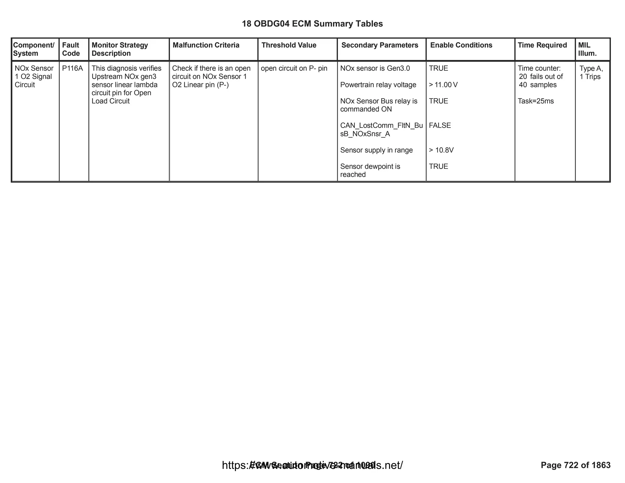


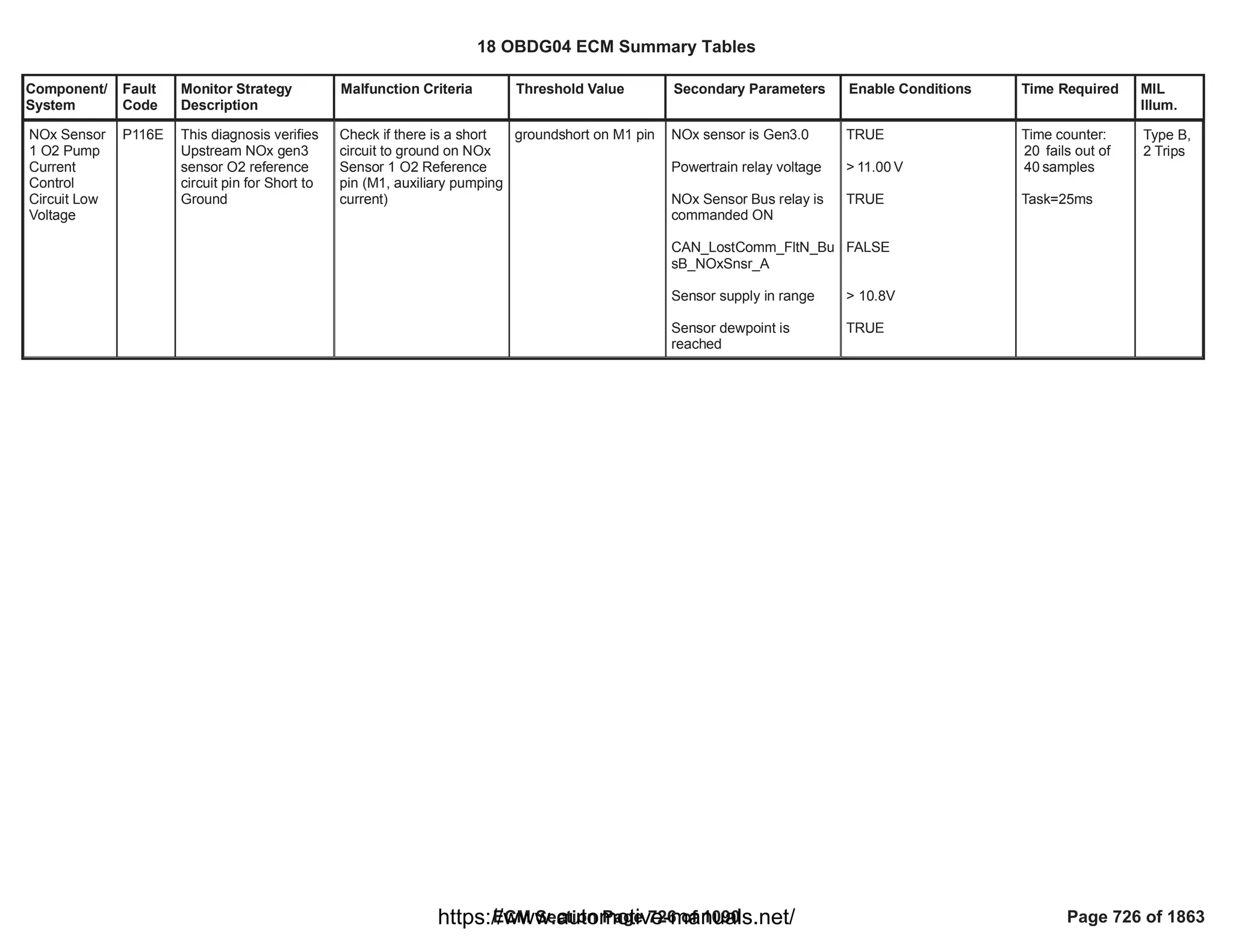

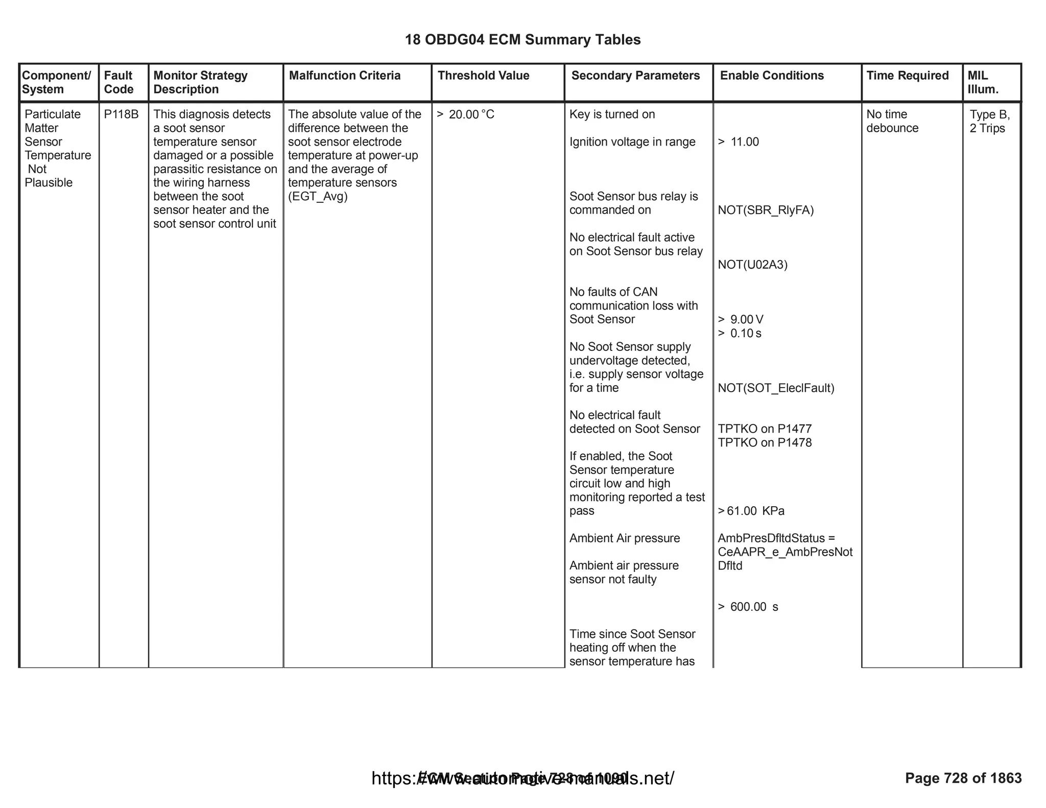
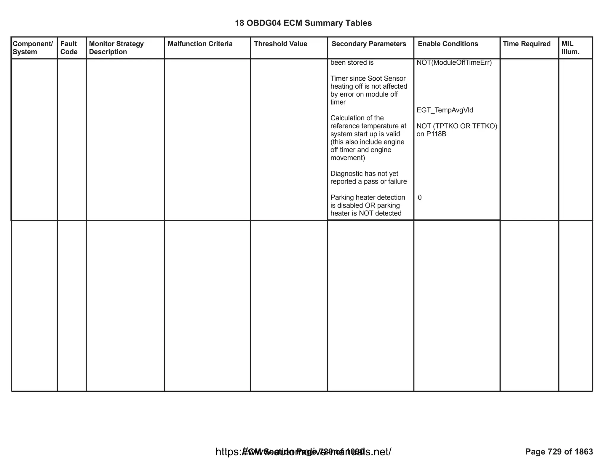


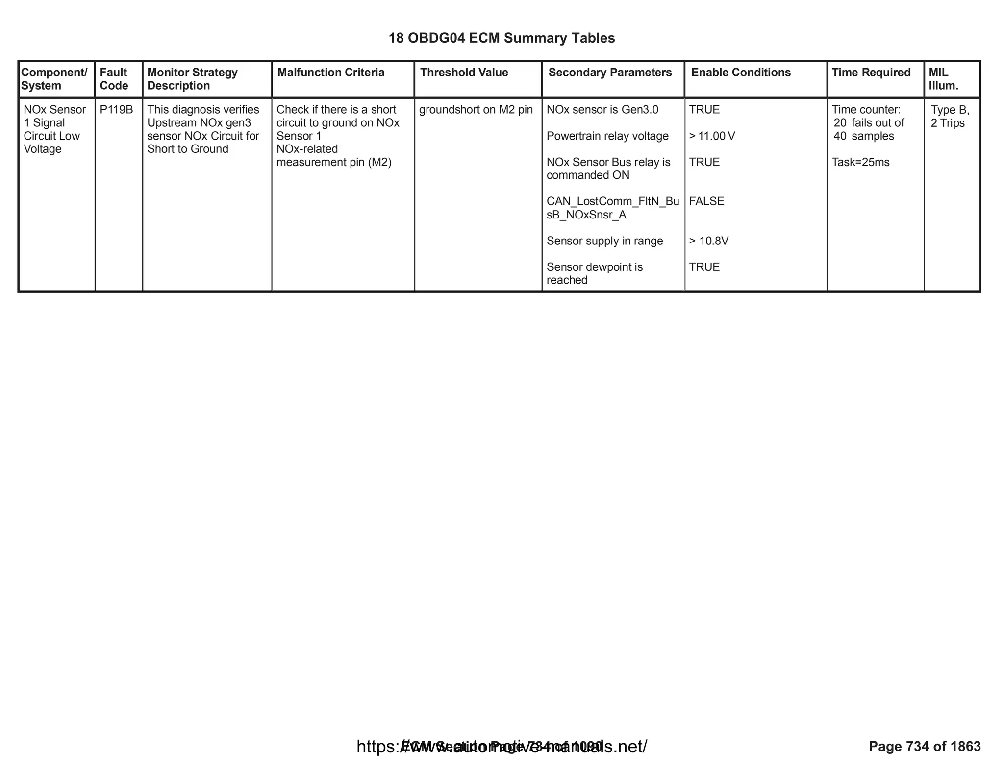

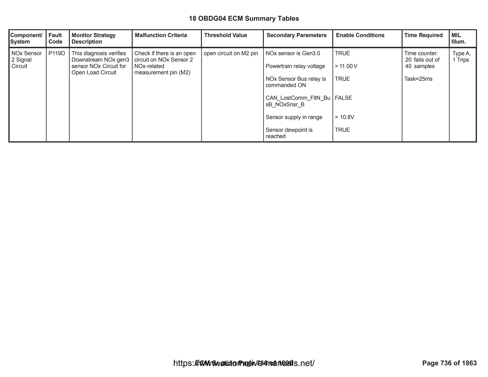


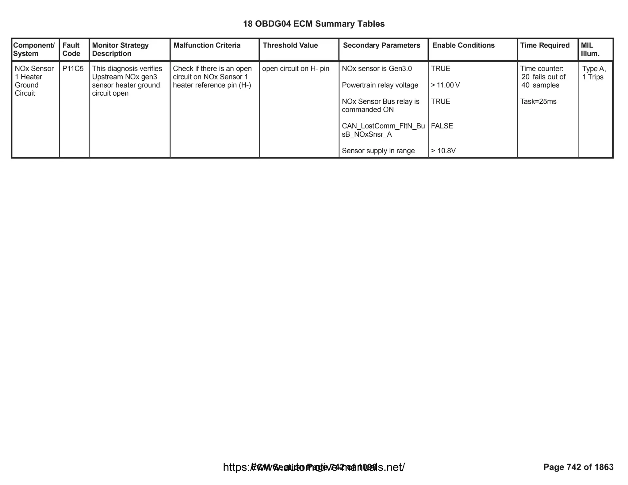


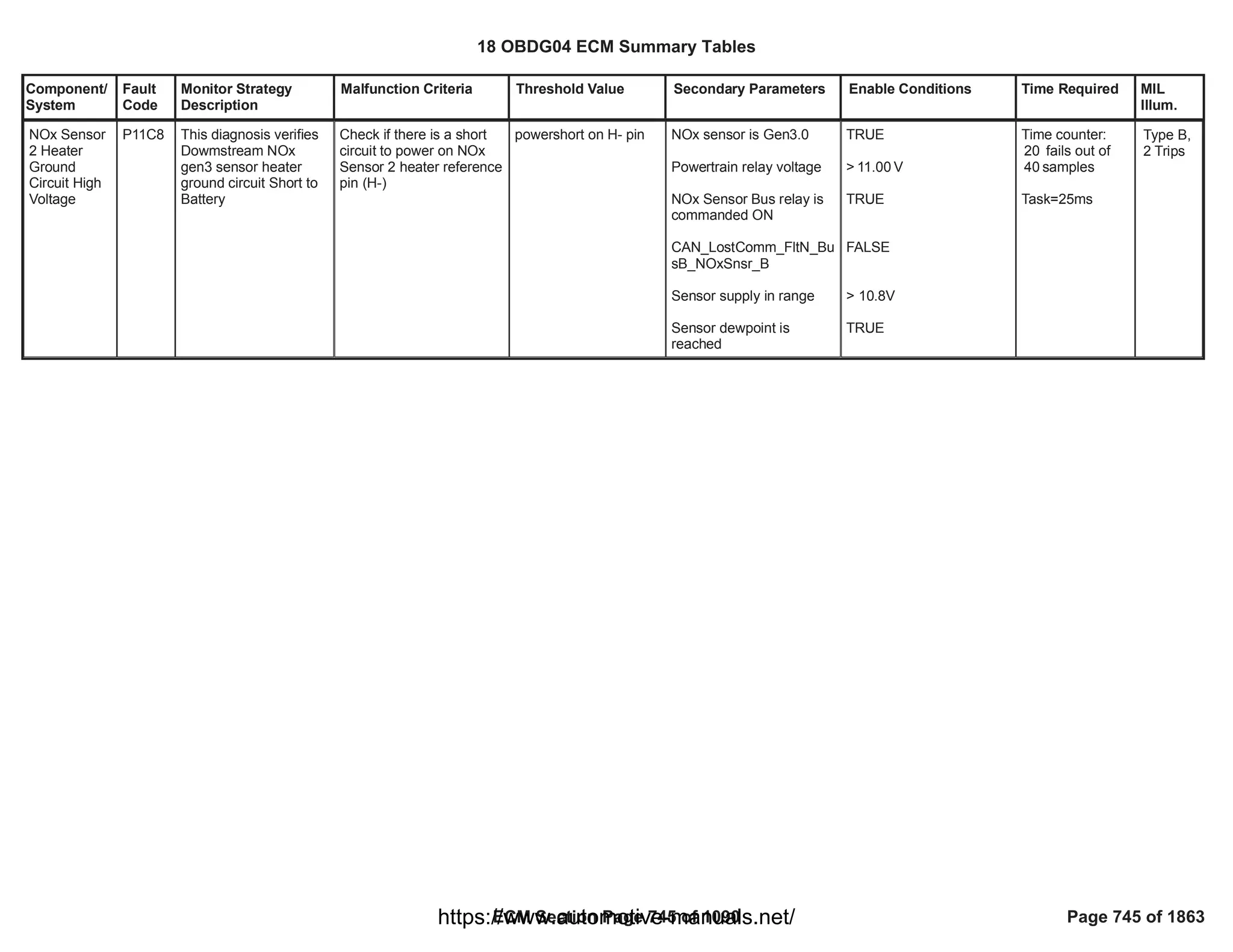
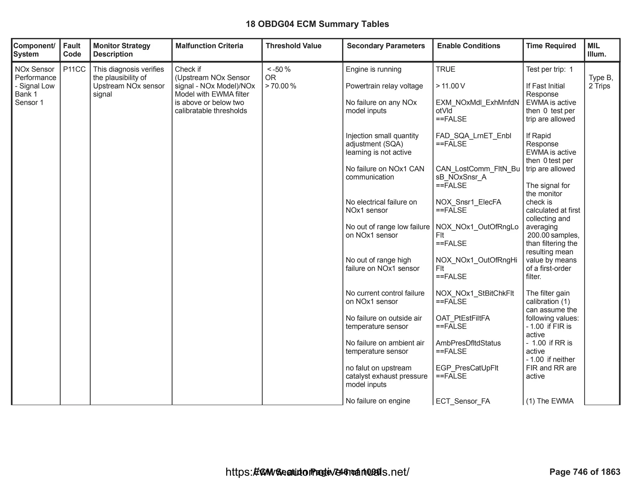
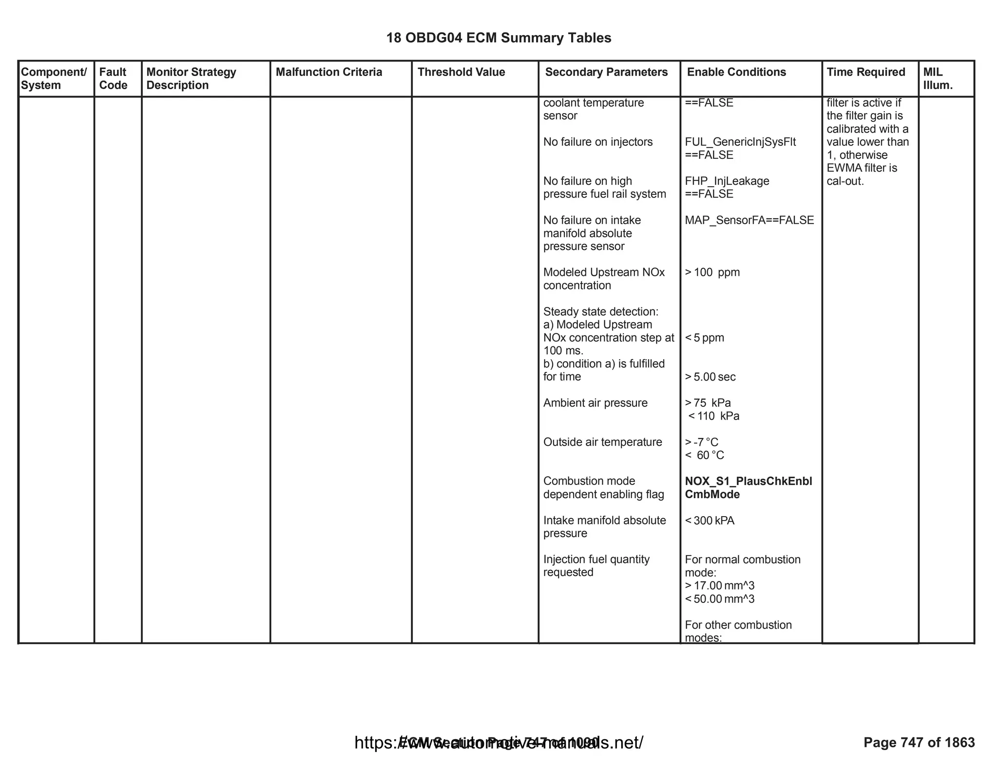
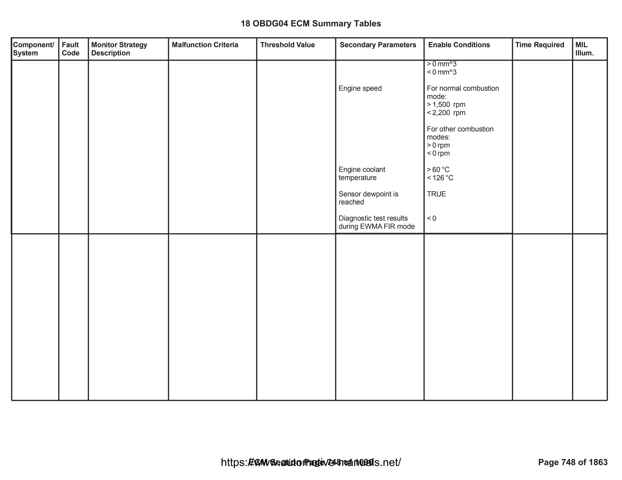


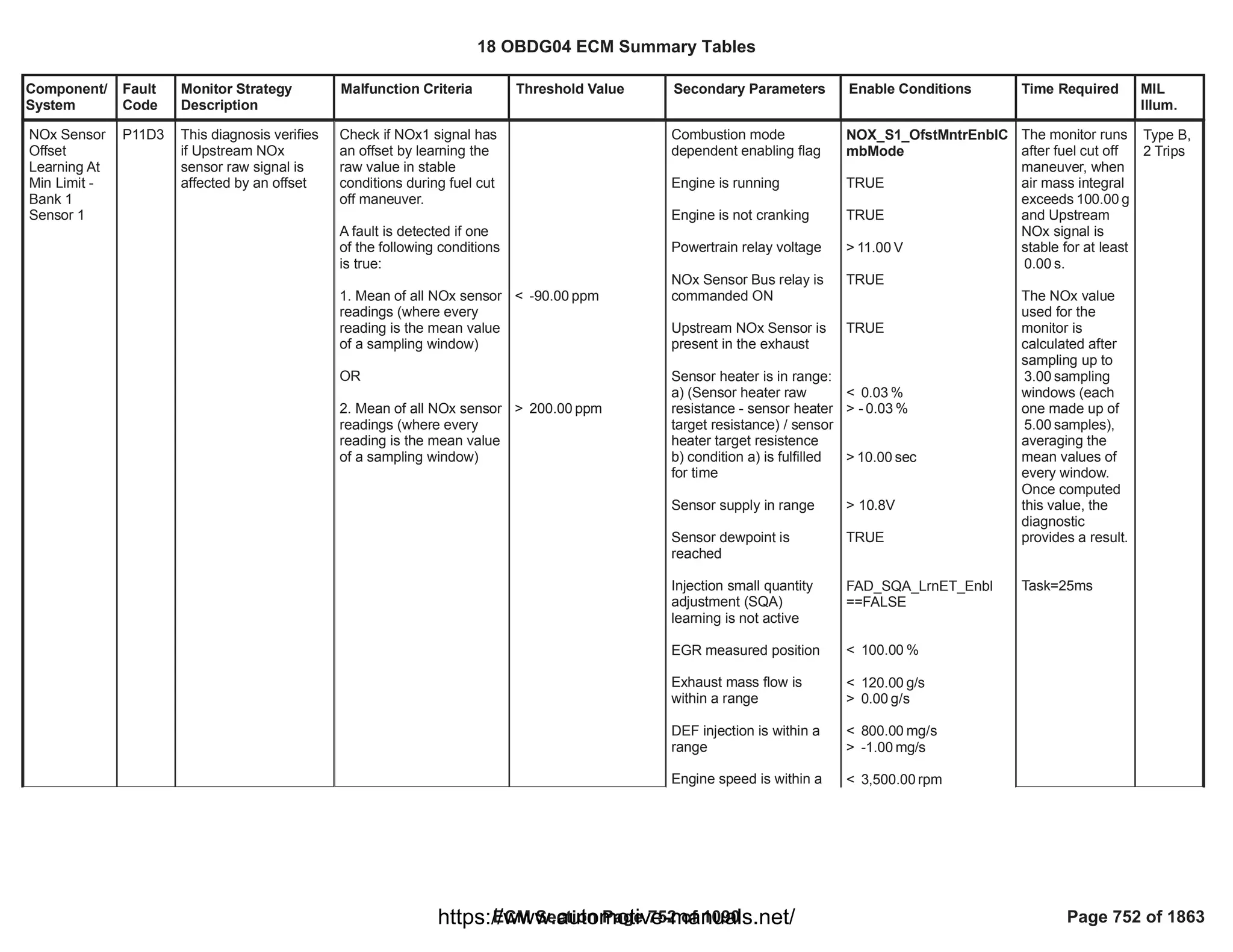
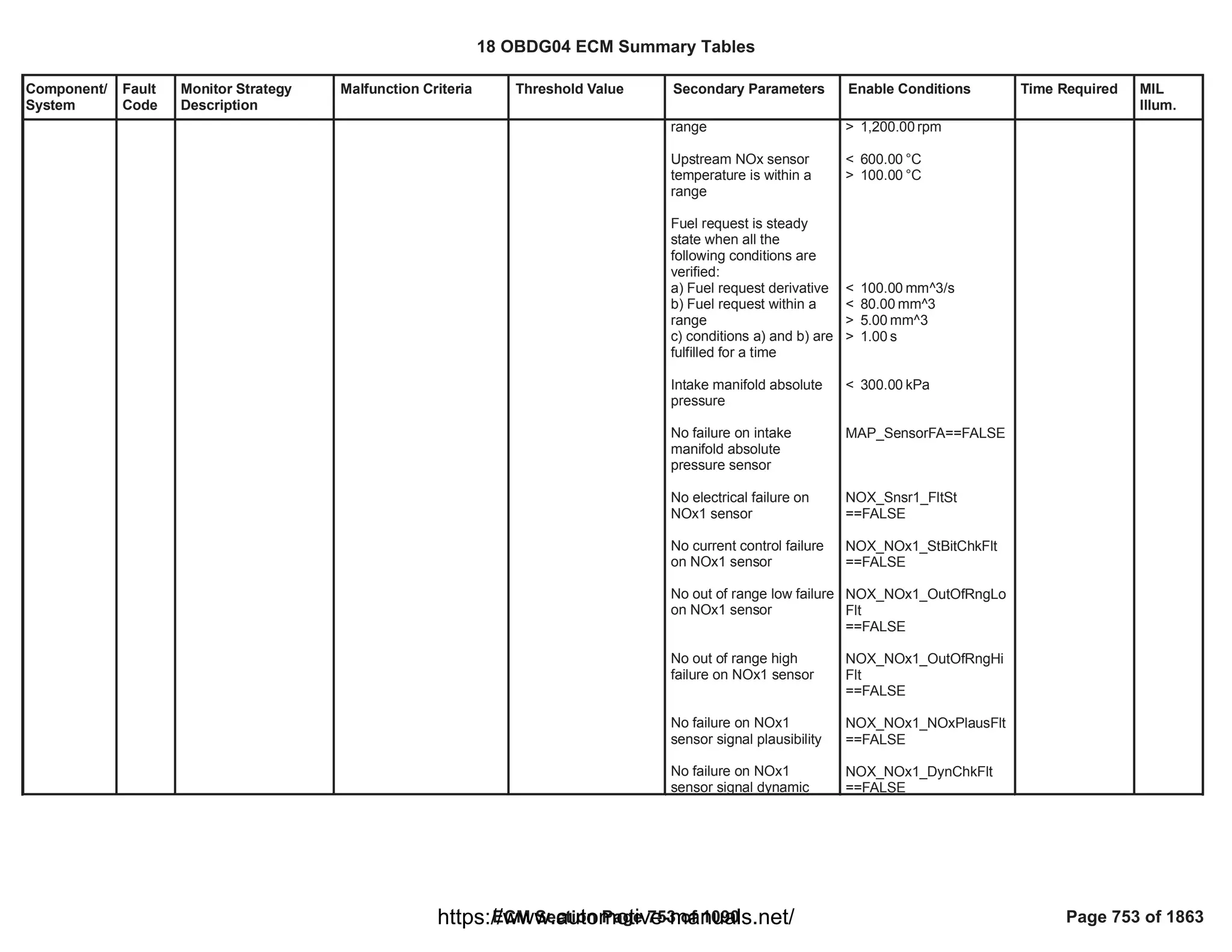
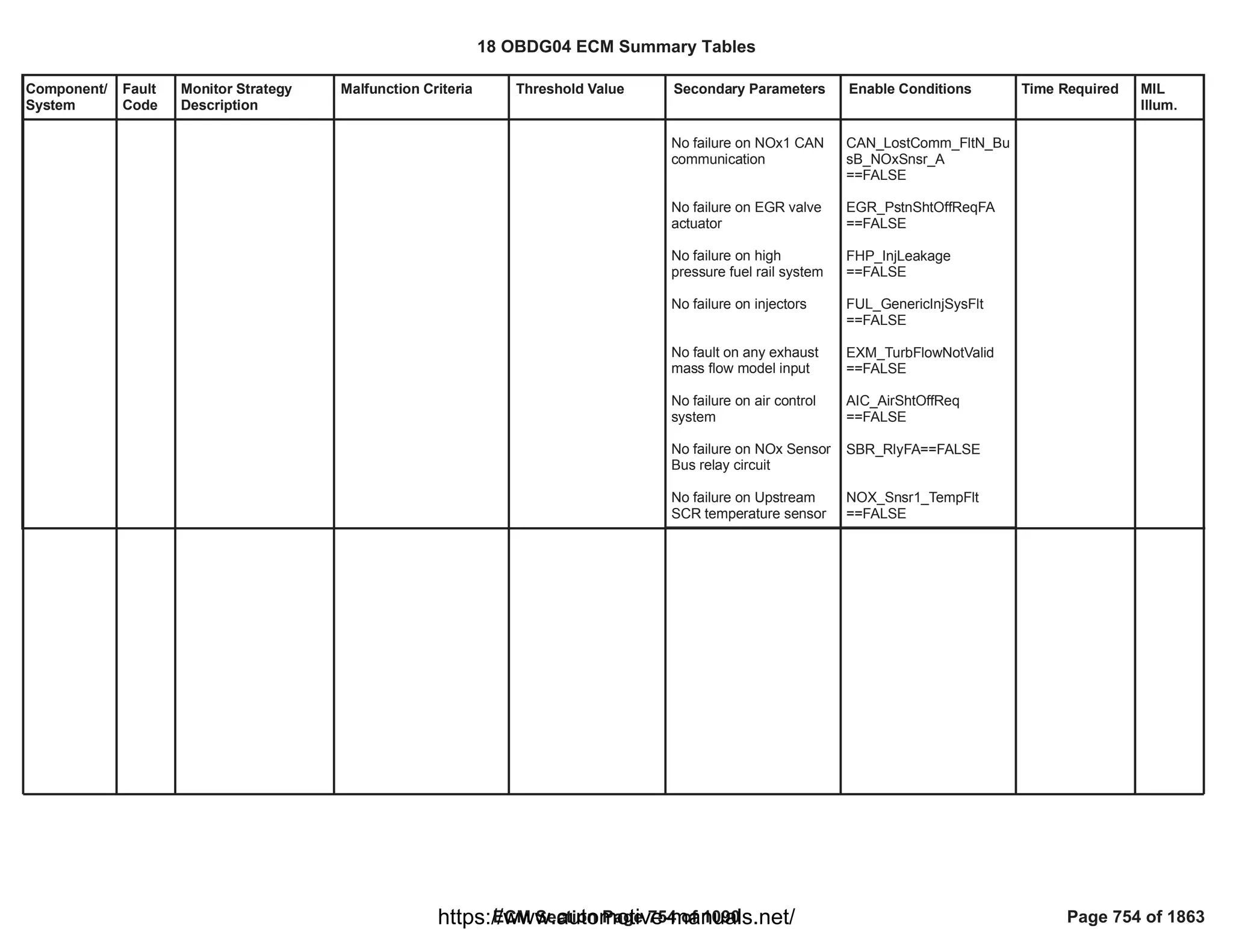

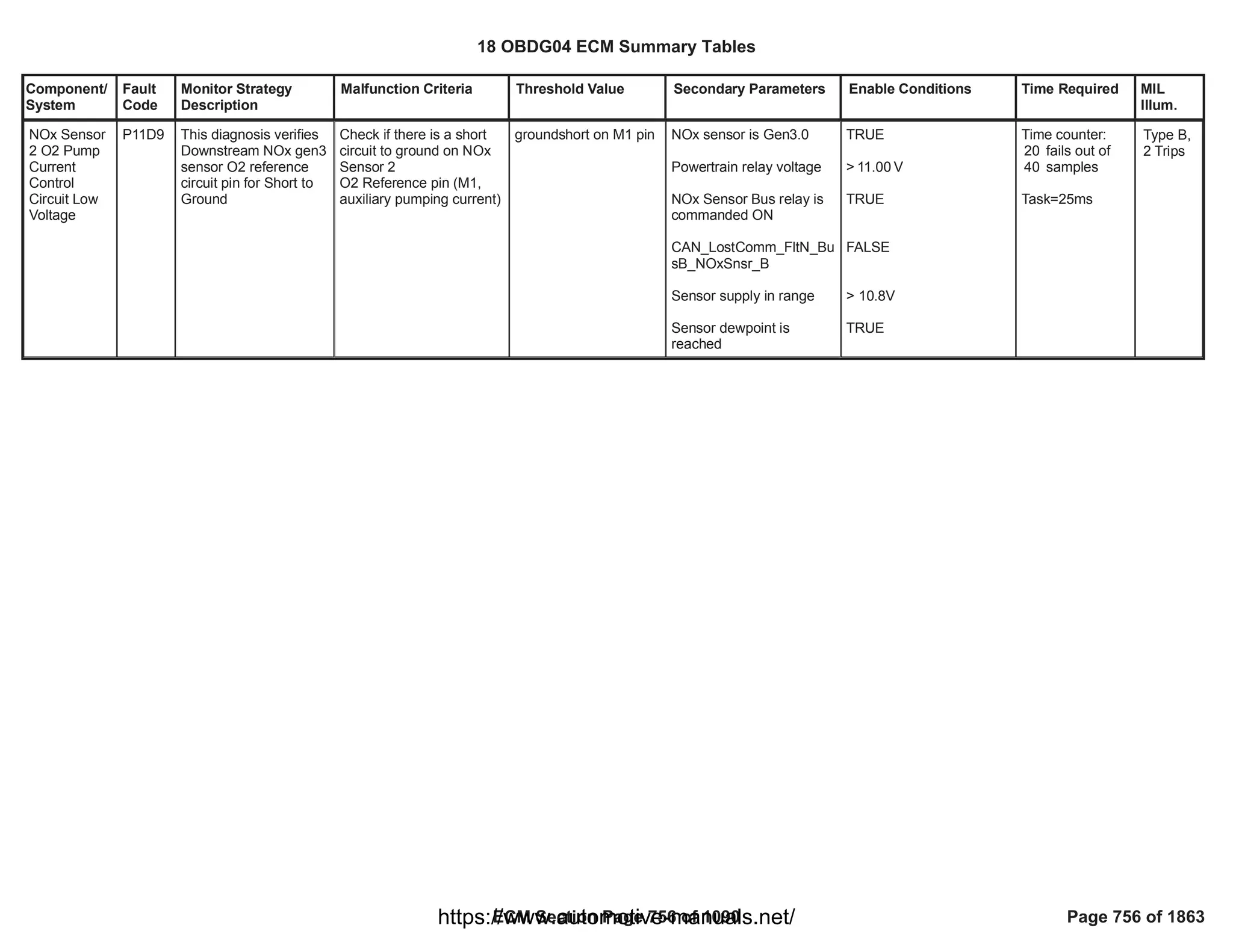

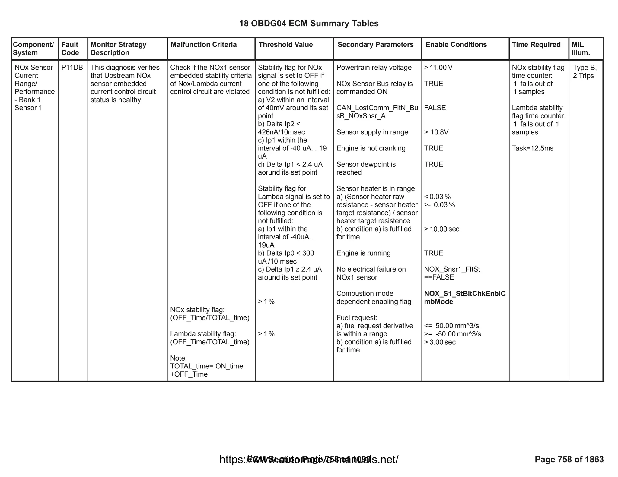
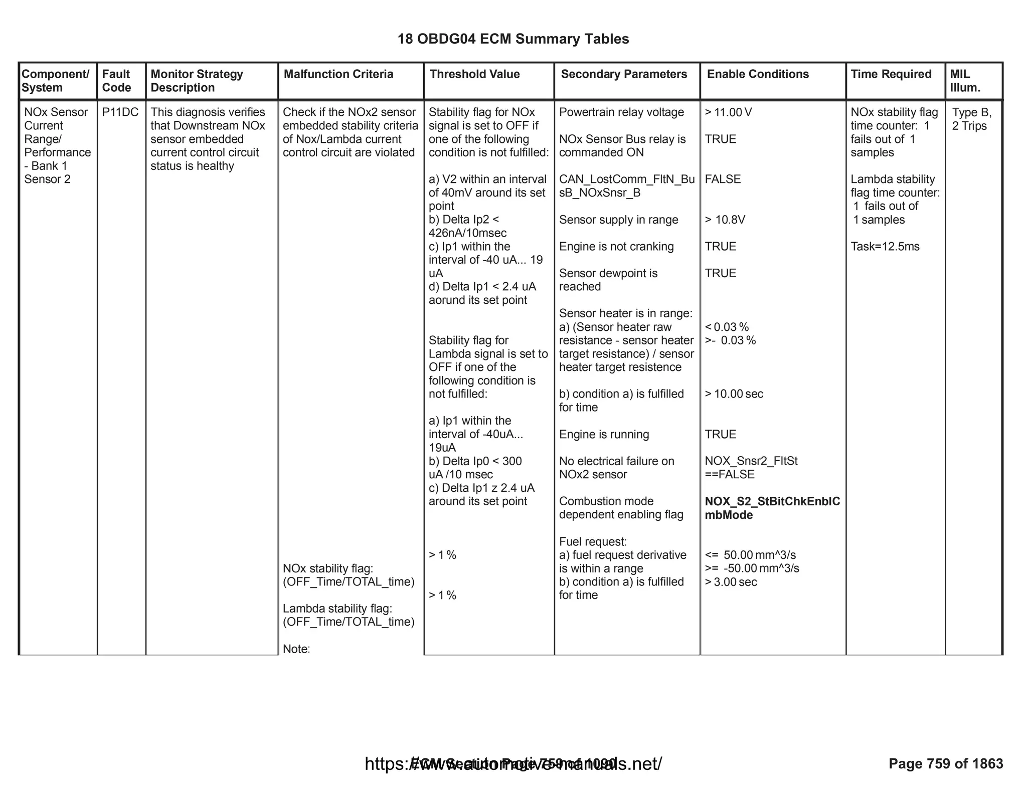


![Component/
System
Fault
Code
Monitor Strategy
Description
Malfunction Criteria Threshold Value Secondary Parameters Enable Conditions Time Required MIL
Illum.
Diesel Intake
Air Flow
Supply
Circuit
P122B This monitor checks if
the Throttle DC-Motor
is correctly supplied
System voltage supply
lower than a threshold
(error information
provided by HWIO)
< 6 [V] Test enabled by
calibration
System out of the
cranking phase
PT relay supply voltage in
range
Diagnostic system
enabled (no clear code or
EOT in progress)
HWIO error status
different from
INDETERMINATE status
== 1.00
> [V]
11.00
96.00
fail counts out of
120.00
sample counts
Function task:
12.5 ms
Type B,
2 Trips
18 OBDG04 ECM Summary Tables
ECM Section Page 764 of 1090 Page 764 of 1863
https://www.automotive-manuals.net/](https://image.slidesharecdn.com/gmcenginefaultcodesdtc1-230327071418-56d3c5bb/75/18-OBDG04-ECM-Summary-Tables-764-2048.jpg)
![Component/
System
Fault
Code
Monitor Strategy
Description
Malfunction Criteria Threshold Value Secondary Parameters Enable Conditions Time Required MIL
Illum.
Diesel Intake
Air Flow
Control
Circuit
Shorted
P122C This monitor checks if
the Throttle commands
are shorted one other
Current flowing through
the H-Bridge switches
higher than a threshold
(error information
provided by HWIO)
> 9 [A] Test enabled by
calibration
System out of the
cranking phase
PT relay supply voltage in
range
H-Bridge driver is ON
Diagnostic system
enabled (no clear code or
EOT in progress)
HWIO error status
different from
INDETERMINATE status
== 1.00
> [V]
11.00
96.00
fail counts out of
120.00
sample counts
Function task:
12.5 ms
Type B,
2 Trips
18 OBDG04 ECM Summary Tables
ECM Section Page 765 of 1090 Page 765 of 1863
https://www.automotive-manuals.net/](https://image.slidesharecdn.com/gmcenginefaultcodesdtc1-230327071418-56d3c5bb/75/18-OBDG04-ECM-Summary-Tables-765-2048.jpg)
![Component/
System
Fault
Code
Monitor Strategy
Description
Malfunction Criteria Threshold Value Secondary Parameters Enable Conditions Time Required MIL
Illum.
Diesel Intake
Air Flow
Position
Sensor
Exceeded
Learning
Limit (SENT
position
sensor)
P122D This monitor checks if
the Throttle position
SENT sensor has an
offset with respect to
the nominal position
where the valve does
the learning procedure
(fully closed)
SENT position raw
voltage when the valve is
in fully closed position <
low threshold
OR
SENT position raw
voltage when the valve is
in fully closed position >
high threshold
< [%5V]
85.80
OR
> [%5V]
93.80
Test enabled by
calibration
Key signal is off
Learning procedure
enabled:
- no faults present on
engine coolant
temperature sensor;
- the engine coolant
tempearture is in range.
Position control in closed
loop: battery voltage
above a threshold.
No faults present on
Throttle position sensor,
Throttle valve, Throttle
position deviation
End Of Trip event has
elapsed
== 1.00
==
ECT_Sensor_FA
FALSE
>= [°C]
60.00
<= [°C]
150.00
> [V]
5.00
==
TPS_PstnShtOffReq
FALSE
1.00
fail counts out of
1.00
sample counts
Function task:
at key off
Type B,
2 Trips
18 OBDG04 ECM Summary Tables
ECM Section Page 766 of 1090 Page 766 of 1863
https://www.automotive-manuals.net/](https://image.slidesharecdn.com/gmcenginefaultcodesdtc1-230327071418-56d3c5bb/75/18-OBDG04-ECM-Summary-Tables-766-2048.jpg)
![Component/
System
Fault
Code
Monitor Strategy
Description
Malfunction Criteria Threshold Value Secondary Parameters Enable Conditions Time Required MIL
Illum.
Diesel Intake
Air Flow
Motor
Overtempera
ture
P1425 This monitor checks if
the temperature of the
Throttle DC-Motor
increases too much
(e.g. Throttle DC-Motor
internal faults, etc).
H-Bridge driver
temperature higher than a
threshold
(error information
provided by HWIO)
> 170 [°C] Test enabled by
calibration
System out of the
cranking phase
PT relay supply voltage in
range
Diagnostic system
enabled (no clear code or
EOT in progress)
HWIO error status
different from
INDETERMINATE status
== 1.00
> [V]
11.00
96.00
fail counts out of
120.00
sample counts
Function task:
12.5 ms
Type B,
2 Trips
18 OBDG04 ECM Summary Tables
ECM Section Page 767 of 1090 Page 767 of 1863
https://www.automotive-manuals.net/](https://image.slidesharecdn.com/gmcenginefaultcodesdtc1-230327071418-56d3c5bb/75/18-OBDG04-ECM-Summary-Tables-767-2048.jpg)
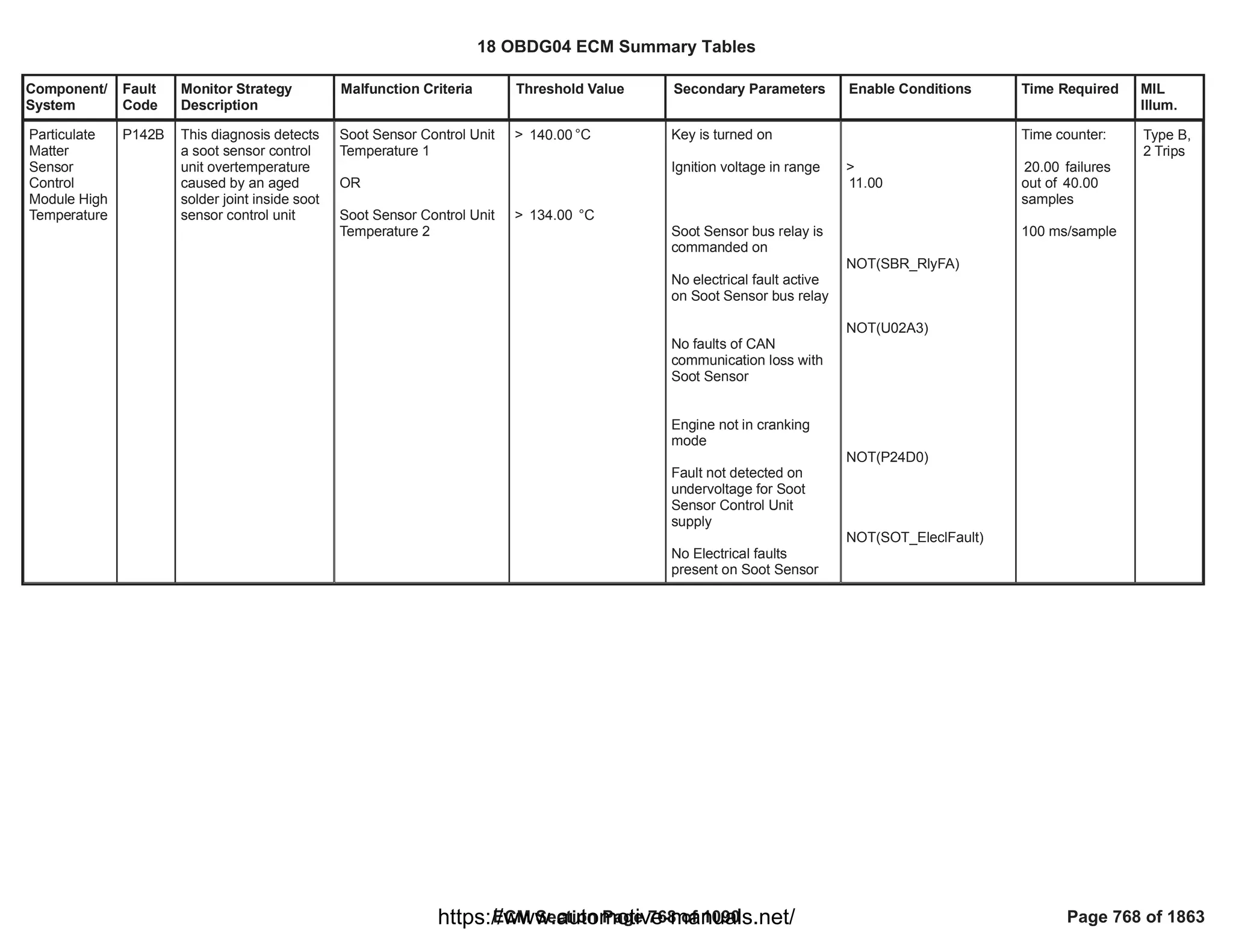
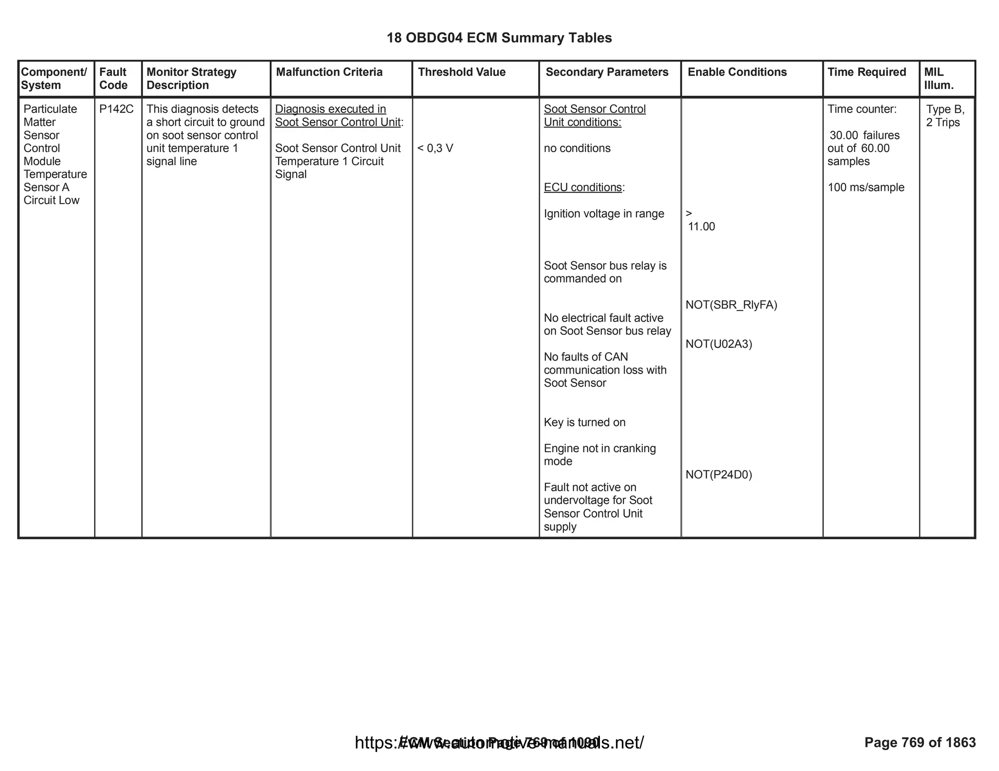


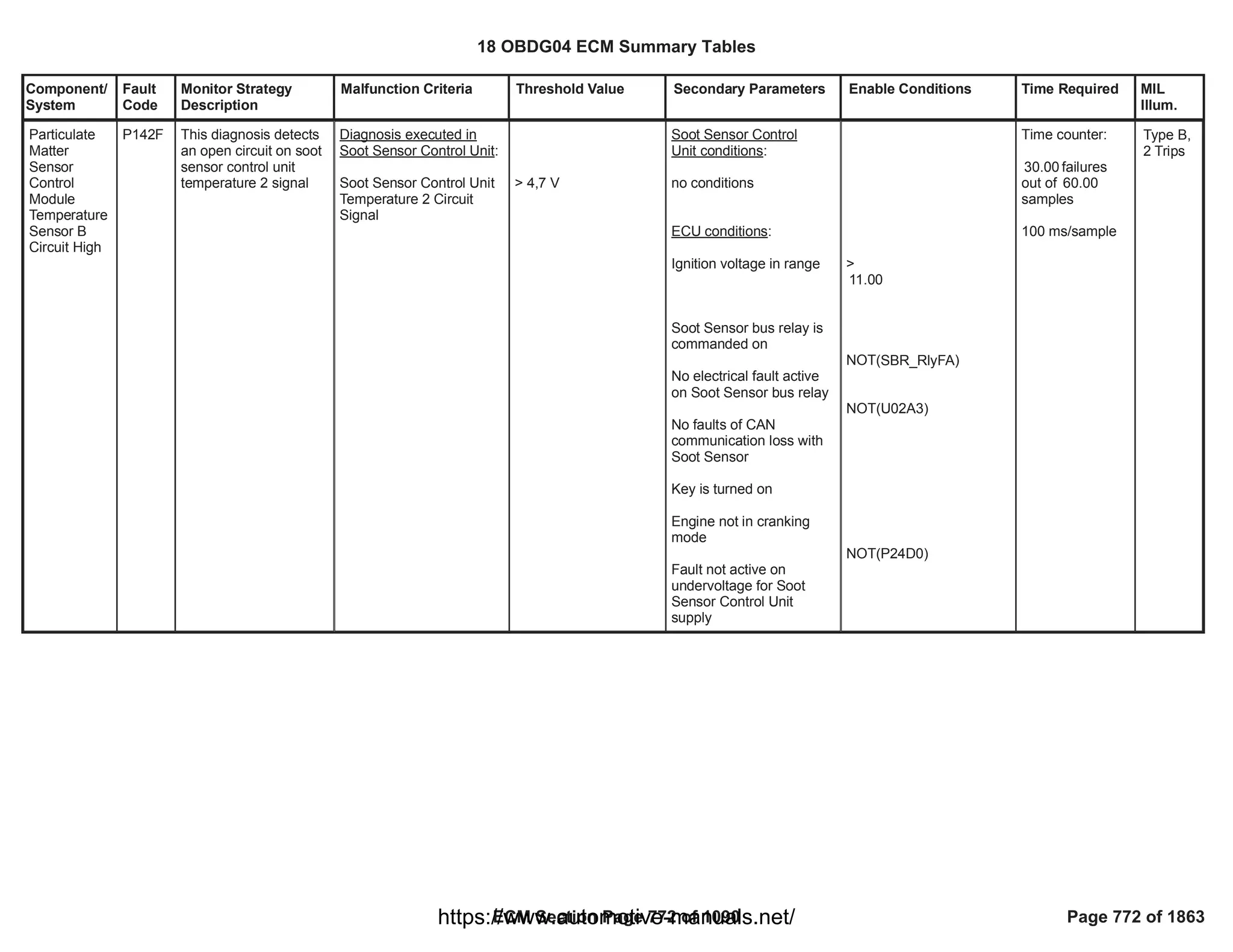
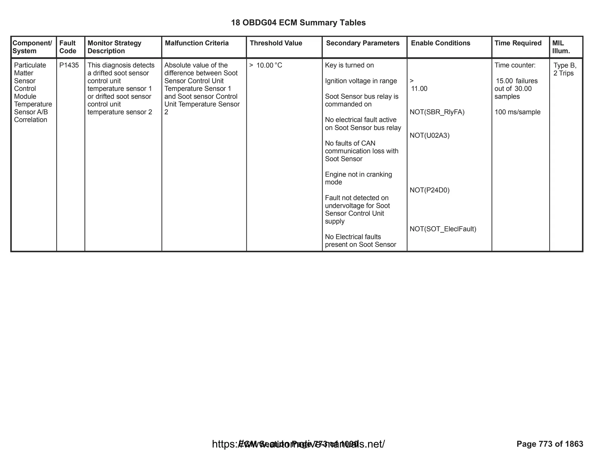
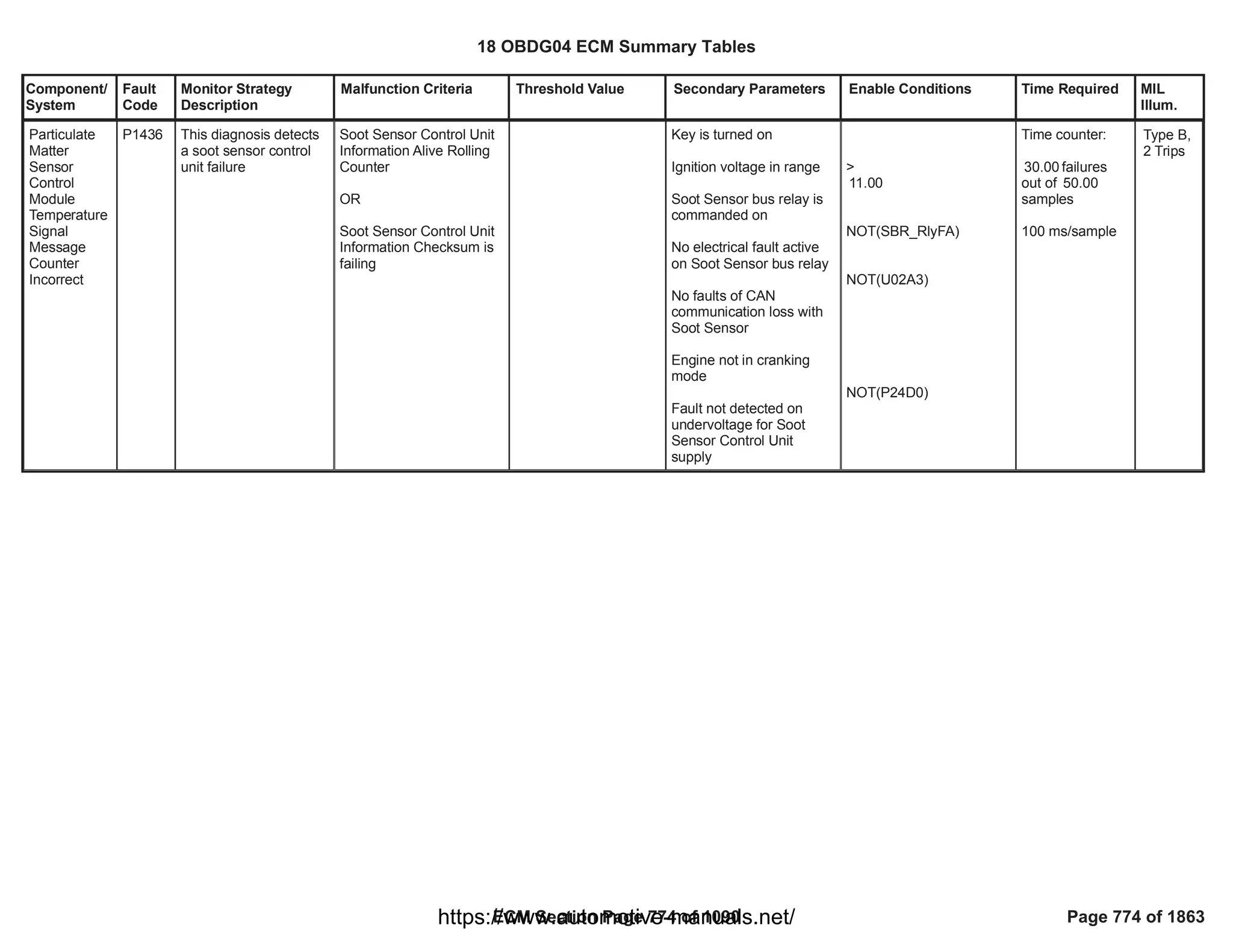
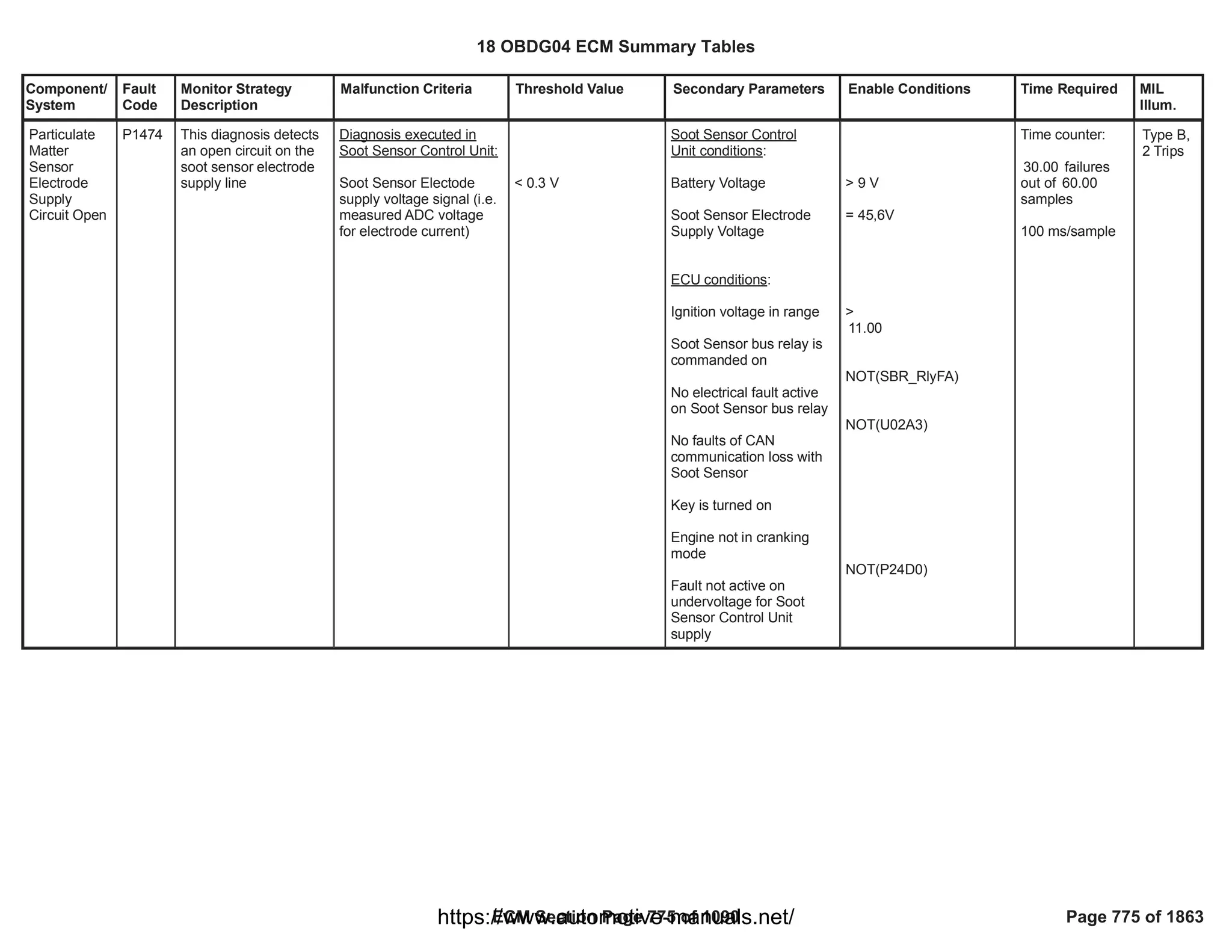
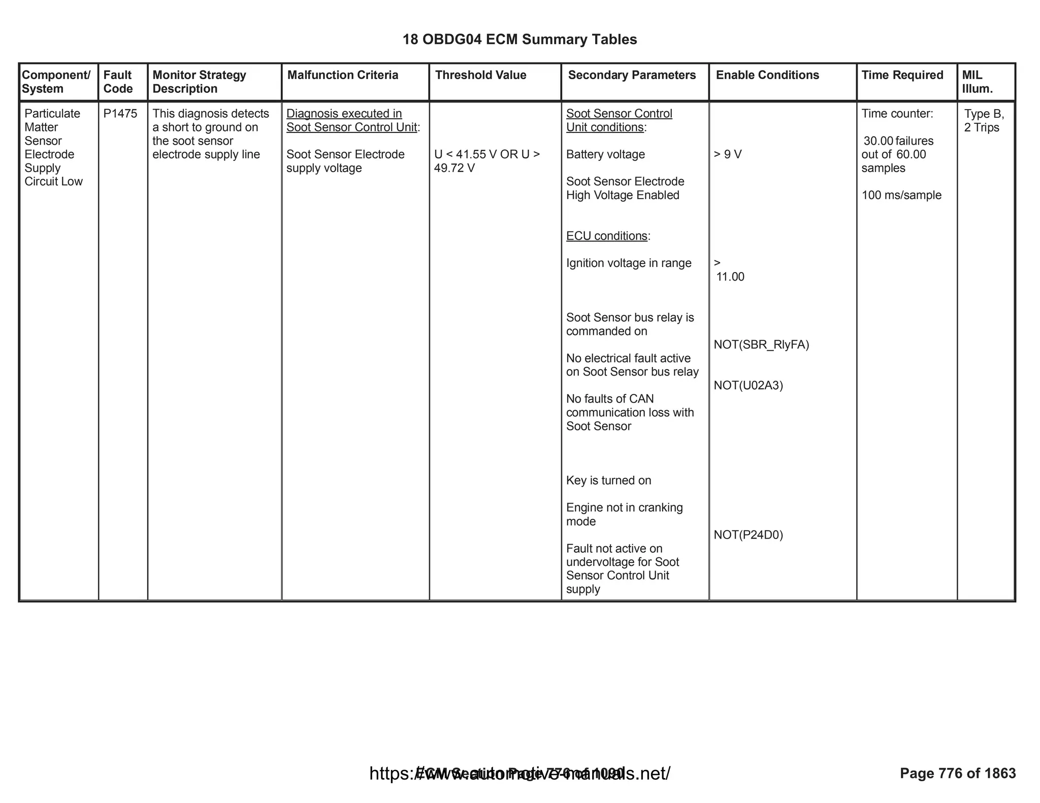
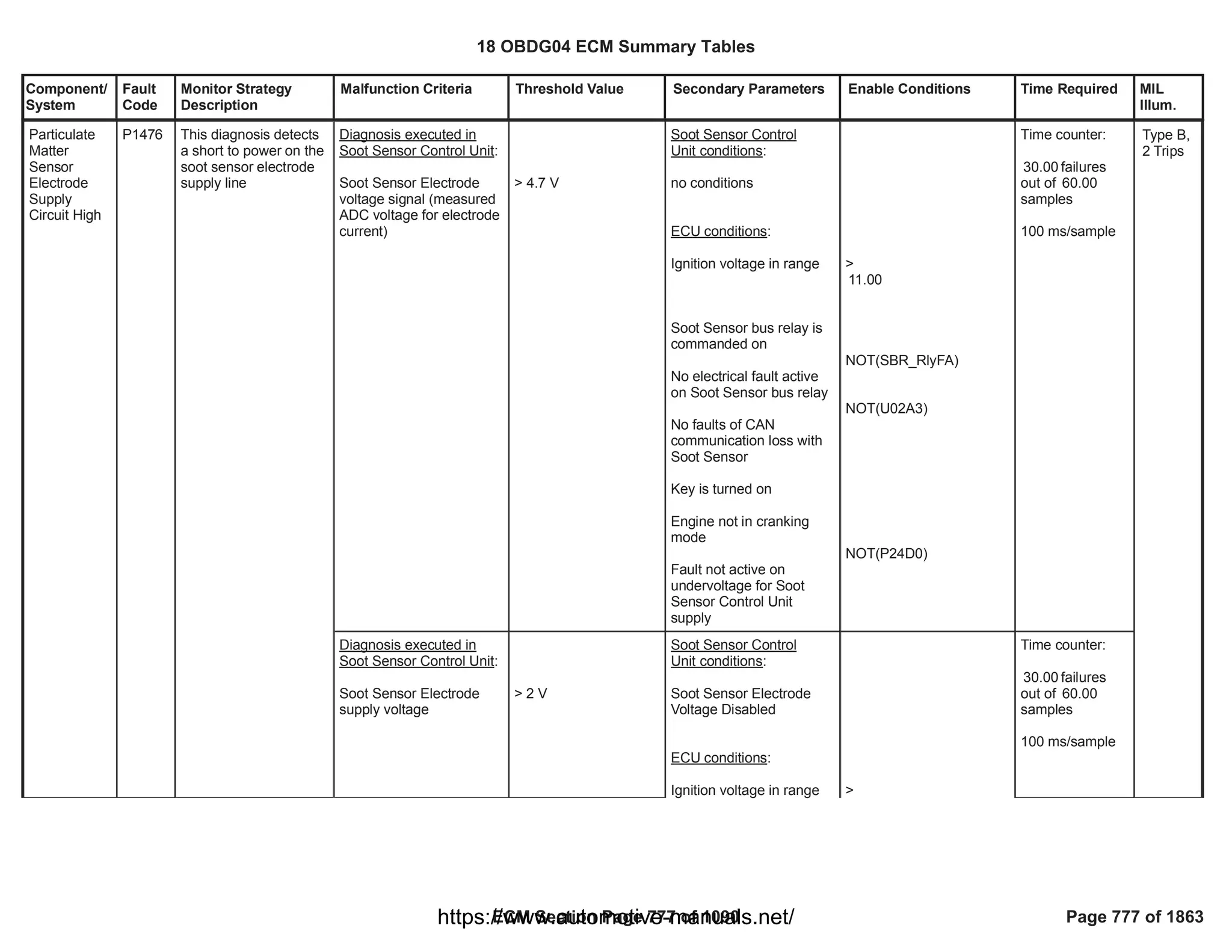
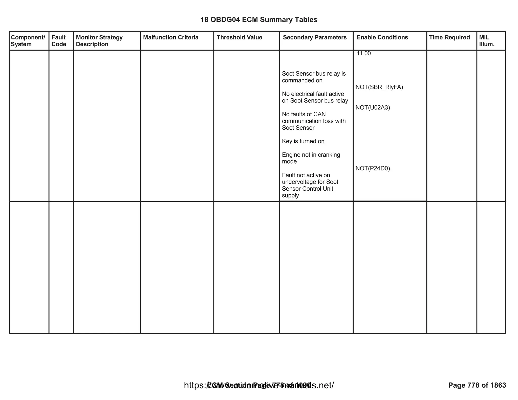


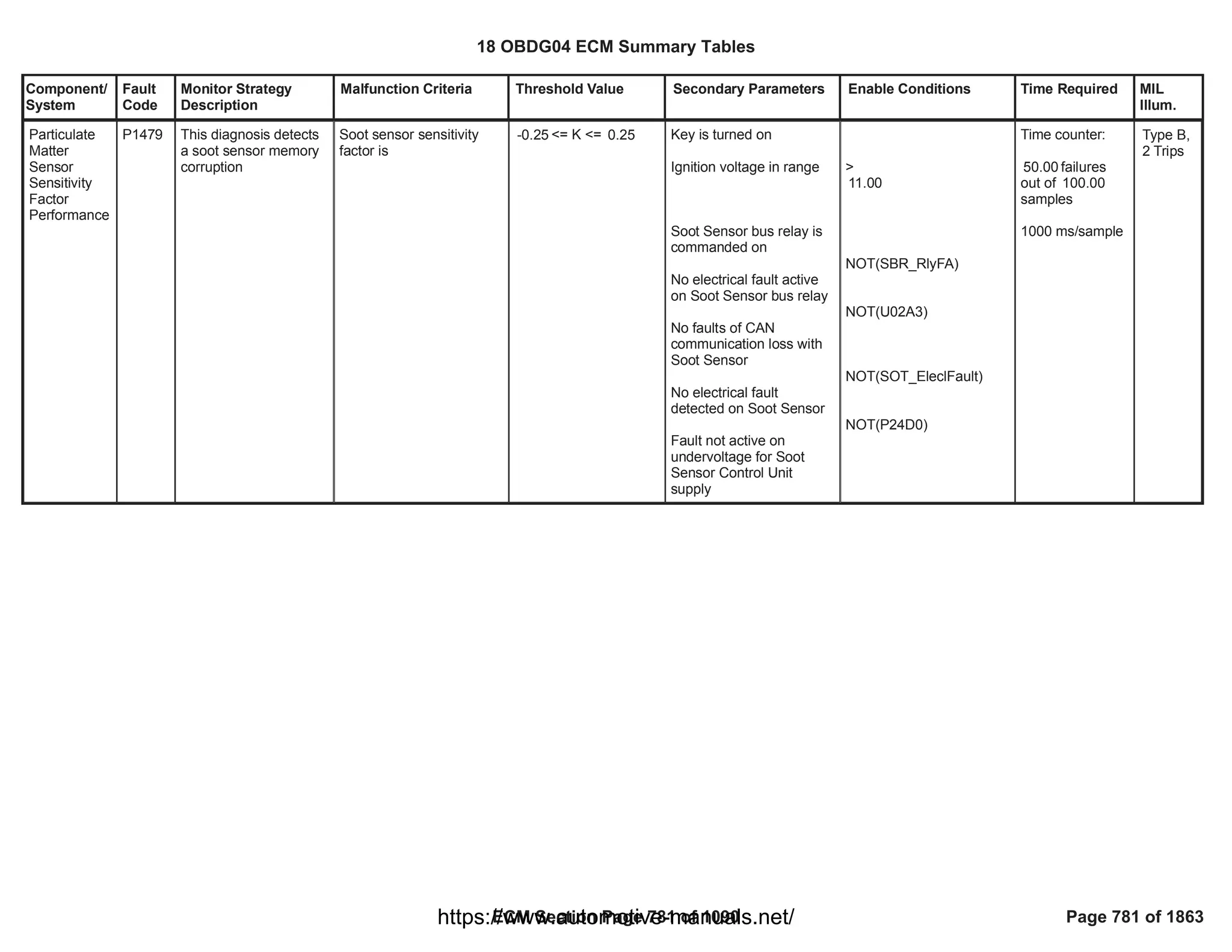
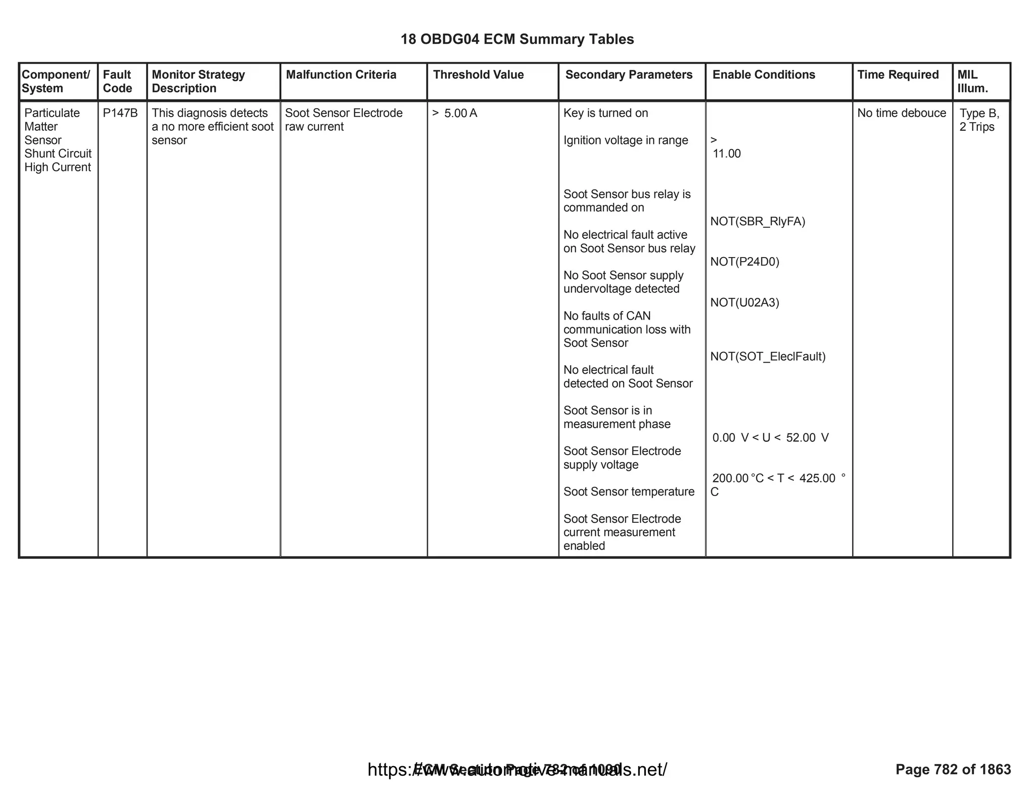
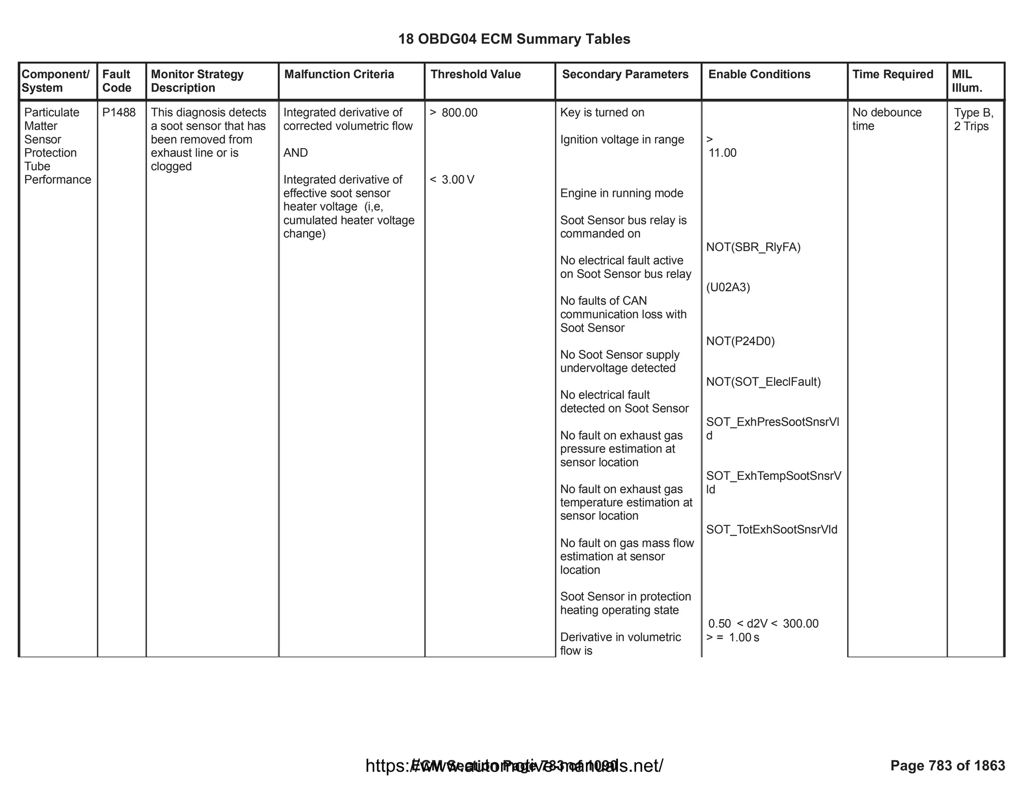
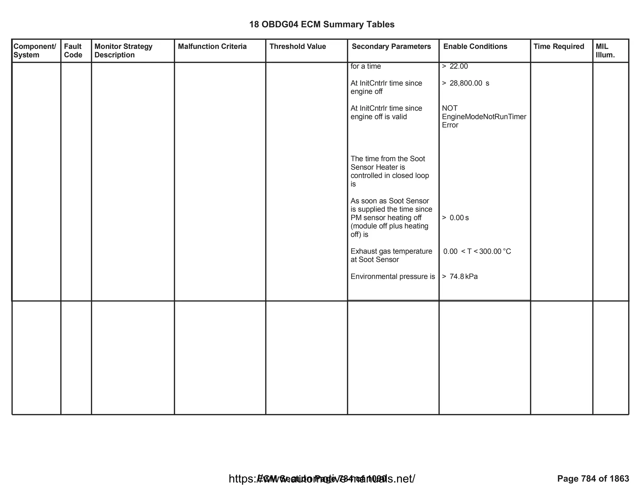
![Component/
System
Fault
Code
Monitor Strategy
Description
Malfunction Criteria Threshold Value Secondary Parameters Enable Conditions Time Required MIL
Illum.
Sensor/
Switch
Communicati
on Circuit A
Low (SENT
position
sensor)
P16A0 This monitor checks if
the Throttle SENT
position sensor
protocol is out of range
low
HWIO counter of valid
Throttle SENT position
indications no longer
updated > threshold (age
error = TRUE)
AND
HWIO Throttle SENT
position protocol status
> [ms]
6.25
AND
== STEADY LOW
Test enabled by
calibration
System out of the
cranking phase
PT relay supply voltage in
range
== 1.00
> [V]
11.00
192.00
fail counts out of
240.00
sample counts
Function task:
6.25 ms
Type B,
2 Trips
18 OBDG04 ECM Summary Tables
ECM Section Page 785 of 1090 Page 785 of 1863
https://www.automotive-manuals.net/](https://image.slidesharecdn.com/gmcenginefaultcodesdtc1-230327071418-56d3c5bb/75/18-OBDG04-ECM-Summary-Tables-785-2048.jpg)
![Component/
System
Fault
Code
Monitor Strategy
Description
Malfunction Criteria Threshold Value Secondary Parameters Enable Conditions Time Required MIL
Illum.
Sensor/
Switch
Communicati
on Circuit A
High (SENT
position
sensor)
P16A1 This monitor checks if
the Throttle SENT
position sensor
protocol is out of range
high
HWIO time counter since
last valid Throttle SENT
position was transmitted >
threshold (age error =
TRUE)
AND
HWIO Throttle SENT
position protocol status
> [ms]
6.25
AND
== STEADY HIGH
Test enabled by
calibration
System out of the
cranking phase
PT relay supply voltage in
range
== 1.00
> [V]
11.00
192.00
fail counts out of
240.00
sample counts
Function task:
6.25 ms
Type B,
2 Trips
18 OBDG04 ECM Summary Tables
ECM Section Page 786 of 1090 Page 786 of 1863
https://www.automotive-manuals.net/](https://image.slidesharecdn.com/gmcenginefaultcodesdtc1-230327071418-56d3c5bb/75/18-OBDG04-ECM-Summary-Tables-786-2048.jpg)
![Component/
System
Fault
Code
Monitor Strategy
Description
Malfunction Criteria Threshold Value Secondary Parameters Enable Conditions Time Required MIL
Illum.
Sensor/
Switch
Communicati
on Circuit A
Performance
(SENT
position
sensor)
P16A2 This monitor checks if
the Throttle SENT
position sensor
protocol has
performance problems
HWIO message fault on
Throttle SENT position ==
TRUE
OR
(
number of Throttle SENT
position counters has
been updated
AND
HWIO time counter since
last valid Throttle SENT
position was transmitted >
threshold (age error =
TRUE)
)
message error ==
TRUE
OR
(
-------------
AND
> [ms]
6.25
)
Test enabled by
calibration
System out of the
cranking phase
PT relay supply voltage in
range
No faults present on
Throttle SENT out of
range
== 1.00
> [V]
11.00
==
TPS_SENT_OOR_Flt
FALSE
192.00
fail counts out of
240.00
sample counts
Function task:
6.25 ms
Type B,
2 Trips
18 OBDG04 ECM Summary Tables
ECM Section Page 787 of 1090 Page 787 of 1863
https://www.automotive-manuals.net/](https://image.slidesharecdn.com/gmcenginefaultcodesdtc1-230327071418-56d3c5bb/75/18-OBDG04-ECM-Summary-Tables-787-2048.jpg)
![Component/
System
Fault
Code
Monitor Strategy
Description
Malfunction Criteria Threshold Value Secondary Parameters Enable Conditions Time Required MIL
Illum.
Intake
Manifold
Runner
Control
Stuck
Closed
(Swirl with
Position
Feedback)
P2006 This monitor checks if
the Swirl actuator got
stuck in closed position
position after P20F8 has
set > threshold
> [%]
100.00 Test enabled by
calibration
System out of the
cranking phase
PT relay supply voltage in
range
Engine coolant
temperature >= threshold
Time elapsed since the
smart actuator switched
on greater than a
threshold
No faults present on
engine coolant
temperature sensor
Outside air temperature
>= threshold
No faults present on
outside air temperature
sensor
Absolute value of position
setpoint is in steady state
conditions for a certain
time
== 1.00
> [V]
11.00
>= [°C]
60.00
>= [s]
5.00
ECT_Sensor_FA
==FALSE
>= [°C]
-7.00
OAT_PtEstFiltFA
==FALSE
< [%/s] for [s]
50.00 0.50
SWC_DrvrCktFA
No debounce is
present: DTC
sets as soon as
the error is
present
Function task:
25 ms
Type A,
1 Trips
18 OBDG04 ECM Summary Tables
ECM Section Page 788 of 1090 Page 788 of 1863
https://www.automotive-manuals.net/](https://image.slidesharecdn.com/gmcenginefaultcodesdtc1-230327071418-56d3c5bb/75/18-OBDG04-ECM-Summary-Tables-788-2048.jpg)
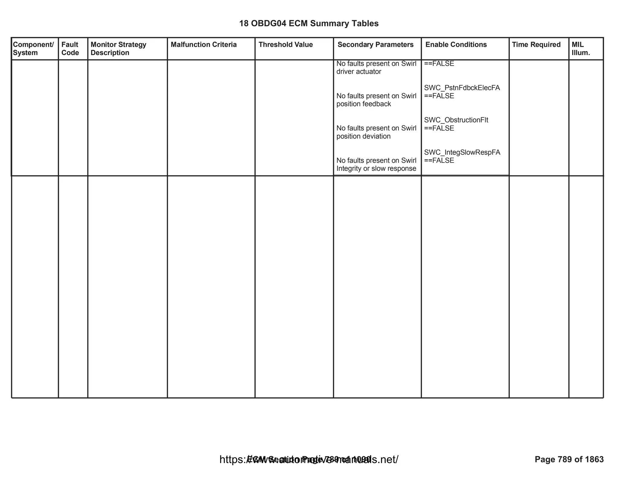
![Component/
System
Fault
Code
Monitor Strategy
Description
Malfunction Criteria Threshold Value Secondary Parameters Enable Conditions Time Required MIL
Illum.
Intake
Manifold
Runner
Control
Control
Circuit (Swirl
with Position
Feedback)
P2008 This monitor checks if
the Swirl command is
in open circuit
Load resistance higher
than a threshold (error
information provided by
HWIO)
> 200 [kOhm] Test enabled by
calibration
System out of the
cranking phase
PT relay supply voltage in
range
== 1.00
> [V]
11.00
12.00
fail counts out of
15.00
sample counts
Function task:
100 ms
Type B,
2 Trips
18 OBDG04 ECM Summary Tables
ECM Section Page 790 of 1090 Page 790 of 1863
https://www.automotive-manuals.net/](https://image.slidesharecdn.com/gmcenginefaultcodesdtc1-230327071418-56d3c5bb/75/18-OBDG04-ECM-Summary-Tables-790-2048.jpg)
![Component/
System
Fault
Code
Monitor Strategy
Description
Malfunction Criteria Threshold Value Secondary Parameters Enable Conditions Time Required MIL
Illum.
Intake
Manifold
Runner
Control
Control
Circuit Low
Voltage
(Swirl with
Position
Feedback)
P2009 This monitor checks if
the Swirl command is
shorted to ground
Resistance to ground
lower than a threshold
(error information
provided by HWIO)
< 0.5 [Ohm] Test enabled by
calibration
System out of the
cranking phase
PT relay supply voltage in
range
== 1.00
> [V]
11.00
12.00
fail counts out of
15.00
sample counts
Function task:
100ms
Type B,
2 Trips
18 OBDG04 ECM Summary Tables
ECM Section Page 791 of 1090 Page 791 of 1863
https://www.automotive-manuals.net/](https://image.slidesharecdn.com/gmcenginefaultcodesdtc1-230327071418-56d3c5bb/75/18-OBDG04-ECM-Summary-Tables-791-2048.jpg)
![Component/
System
Fault
Code
Monitor Strategy
Description
Malfunction Criteria Threshold Value Secondary Parameters Enable Conditions Time Required MIL
Illum.
raw position when the
flaps are in fully closed
position <
low threshold
OR
raw position when the
flaps are in fully closed
position >
high threshold
OR
raw position when the
flaps are in fully open
position <
low threshold
OR
raw position when the
flaps are in fully open
position >
highthreshold
< [%]
81.00
OR
> [%]
92.00
OR
< [%5V]
25.00
OR
> [%5V]
40.00
Test enabled by
calibration
System out of the
cranking phase
PT relay supply voltage in
range
Engine coolant
temperature greater than
threshold
No faults present on
engine coolant
temperature sensor
No faults present on Swirl
driver actuator
No faults present on Swirl
position feedback
End Of Trip event has
elapsed
== 1.00
> [V]
11.00
>= [°C]
60.00
ECT_Sensor_FA
==FALSE
SWC_DrvrCktFA
==FALSE
SWC_PstnFdbckElecFA
==FALSE
No debounce is
present: DTC
sets as soon as
the error is
present
Function task:
at key off
Intake
Manifold
Runner
Performance
(Swirl with
Position
Feedback)
P200A This monitor checks if
the Swirl mechanical
stop learnings are
inside the plausible
range and if the valve
is not excessively slow
Type B,
2 Trips
18 OBDG04 ECM Summary Tables
ECM Section Page 792 of 1090 Page 792 of 1863
https://www.automotive-manuals.net/](https://image.slidesharecdn.com/gmcenginefaultcodesdtc1-230327071418-56d3c5bb/75/18-OBDG04-ECM-Summary-Tables-792-2048.jpg)
![Component/
System
Fault
Code
Monitor Strategy
Description
Malfunction Criteria Threshold Value Secondary Parameters Enable Conditions Time Required MIL
Illum.
response time in closing
direction > high threshold
OR
response time in opening
direction > high threshold
OR
total time needed to
complete either closing or
opening phase of the slow
response test >= high
threshold
> [s]
5.00
OR
> [s]
5.00
OR
>= [s]
10.00
Test enabled by
calibration
System out of the
cranking phase
PT relay supply voltage in
range
Engine coolant
temperature greater than
threshold
Time elapsed since the
smart actuator switched
on greater than a
threshold
No faults present on
engine coolant
temperature sensor
No faults present on Swirl
driver actuator
No faults present on Swirl
position feedback
End Of Trip event has
elapsed
== 1.00
> [V]
11.00
>= [°C]
60.00
>= [s]
5.00
ECT_Sensor_FA
==FALSE
SWC_DrvrCktFA
==FALSE
SWC_PstnFdbckElecFA
==FALSE
No debounce is
present: DTC
sets as soon as
the error is
present
Function task:
at key off
18 OBDG04 ECM Summary Tables
ECM Section Page 793 of 1090 Page 793 of 1863
https://www.automotive-manuals.net/](https://image.slidesharecdn.com/gmcenginefaultcodesdtc1-230327071418-56d3c5bb/75/18-OBDG04-ECM-Summary-Tables-793-2048.jpg)
![Component/
System
Fault
Code
Monitor Strategy
Description
Malfunction Criteria Threshold Value Secondary Parameters Enable Conditions Time Required MIL
Illum.
Intake
Manifold
Runner
Control
Circuit High
Voltage
(Swirl with
Position
Feedback)
P2010 This monitor checks if
the Swirl command
isshorted to power
supply
Resistance to supply
lower than a threshold
(error information
provided by HWIO)
< 0.5 [Ohm] Test enabled by
calibration
System out of the
cranking phase
PT relay supply voltage in
range
== 1.00
> [V]
11.00
12.00
fail counts out of
15.00
sample counts
Function task:
100ms
Type B,
2 Trips
18 OBDG04 ECM Summary Tables
ECM Section Page 794 of 1090 Page 794 of 1863
https://www.automotive-manuals.net/](https://image.slidesharecdn.com/gmcenginefaultcodesdtc1-230327071418-56d3c5bb/75/18-OBDG04-ECM-Summary-Tables-794-2048.jpg)
![Component/
System
Fault
Code
Monitor Strategy
Description
Malfunction Criteria Threshold Value Secondary Parameters Enable Conditions Time Required MIL
Illum.
Intake
Manifold
Runner
Position
Sensor
Range/
Performance
(Swirl with
Position
Feedback)
P2015 This monitor checks if
the Swirl position
feedback has a
frequency too high or
too low
(
Swirl position pulse period
< low threshold
OR
Swirl position pulse period
> high threshold
)
AND
Swirl duty cycle
AND
Swirl duty cycle
< [ms]
0.00
> [ms]
64.00
!= 0%
!= 100%
Test enabled by
calibration
System out of the
cranking phase
Time elapsed since the
smart actuator switched
on greater than a
threshold
PT relay supply voltage in
range
== 1.00
>= [s]
5.00
> [V]
11.00
52.00
fail counts out of
62.00
sample counts
Function task:
25 ms
Type B,
2 Trips
18 OBDG04 ECM Summary Tables
ECM Section Page 795 of 1090 Page 795 of 1863
https://www.automotive-manuals.net/](https://image.slidesharecdn.com/gmcenginefaultcodesdtc1-230327071418-56d3c5bb/75/18-OBDG04-ECM-Summary-Tables-795-2048.jpg)
![Component/
System
Fault
Code
Monitor Strategy
Description
Malfunction Criteria Threshold Value Secondary Parameters Enable Conditions Time Required MIL
Illum.
Intake
Manifold
Runner
Position
Sensor
Circuit Low
(Swirl with
Position
Feedback)
P2016 This monitor checks if
the Swirl position
feedback is out of
electrical range low
Swirl position pulse period
== maximum constant
pulse period
AND
Swirl duty cycle
== [ms]
30.00
== 0%
Test enabled by
calibration
System out of the
cranking phase
Time elapsed since the
smart actuator switched
on greater than a
threshold
PT relay supply voltage in
range
== 1.00
>= [s]
5.00
> [V]
11.00
50.00
fail counts out of
62.00
sample counts
Function task:
25 ms
Type B,
2 Trips
18 OBDG04 ECM Summary Tables
ECM Section Page 796 of 1090 Page 796 of 1863
https://www.automotive-manuals.net/](https://image.slidesharecdn.com/gmcenginefaultcodesdtc1-230327071418-56d3c5bb/75/18-OBDG04-ECM-Summary-Tables-796-2048.jpg)
![Component/
System
Fault
Code
Monitor Strategy
Description
Malfunction Criteria Threshold Value Secondary Parameters Enable Conditions Time Required MIL
Illum.
Intake
Manifold
Runner
Position
Sensor
Circuit High
(Swirl with
Position
Feedback)
P2017 This monitor checks if
the Swirl position
feedback is out of
electrical range high
Swirl position pulse period
== maximum constant
pulse period
AND
Swirl duty cycle
== [ms]
30.00
== 100%
Test enabled by
calibration
System out of the
cranking phase
Time elapsed since the
smart actuator switched
on greater than a
threshold
PT relay supply voltage in
range
== 1.00
>= [s]
5.00
> [V]
11.00
50.00
fail counts out of
62.00
sample counts
Function task:
25 ms
Type B,
2 Trips
18 OBDG04 ECM Summary Tables
ECM Section Page 797 of 1090 Page 797 of 1863
https://www.automotive-manuals.net/](https://image.slidesharecdn.com/gmcenginefaultcodesdtc1-230327071418-56d3c5bb/75/18-OBDG04-ECM-Summary-Tables-797-2048.jpg)
![Component/
System
Fault
Code
Monitor Strategy
Description
Malfunction Criteria Threshold Value Secondary Parameters Enable Conditions Time Required MIL
Illum.
Intake
Manifold
Runner
Control
Circuit
Performance
(Swirl with
Position
Feedback)
P20F8 This monitor checks if
the Swirl flaps got
mechanically stuck in
any positions
Absolute value of position
tracking error (setpoint
position - measured
position) >
positive threshold
> [%]
10.00 Test enabled by
calibration
System out of the
cranking phase
PT relay supply voltage in
range
Engine coolant
temperature >= threshold
Time elapsed since the
smart actuator switched
on greater than a
threshold
No faults present on
engine coolant
temperature sensor
Outside airtemperature >=
threshold
No faults present on
outside airtemperature
sensor
Absolute value of position
setpoint is in steady state
conditions for a certain
time
No faults present on Swirl
== 1.00
> [V]
11.00
>= [°C]
60.00
>= [s]
5.00
ECT_Sensor_FA
==FALSE
>= [°C]
-7.00
OAT_PtEstFiltFA
==FALSE
< [%/s] for [s]
50.00 0.50
SWC_DrvrCktFA
==FALSE
80.00
fail counts out of
100.00
sample counts
Function task:
25 ms
Type B,
2 Trips
18 OBDG04 ECM Summary Tables
ECM Section Page 798 of 1090 Page 798 of 1863
https://www.automotive-manuals.net/](https://image.slidesharecdn.com/gmcenginefaultcodesdtc1-230327071418-56d3c5bb/75/18-OBDG04-ECM-Summary-Tables-798-2048.jpg)
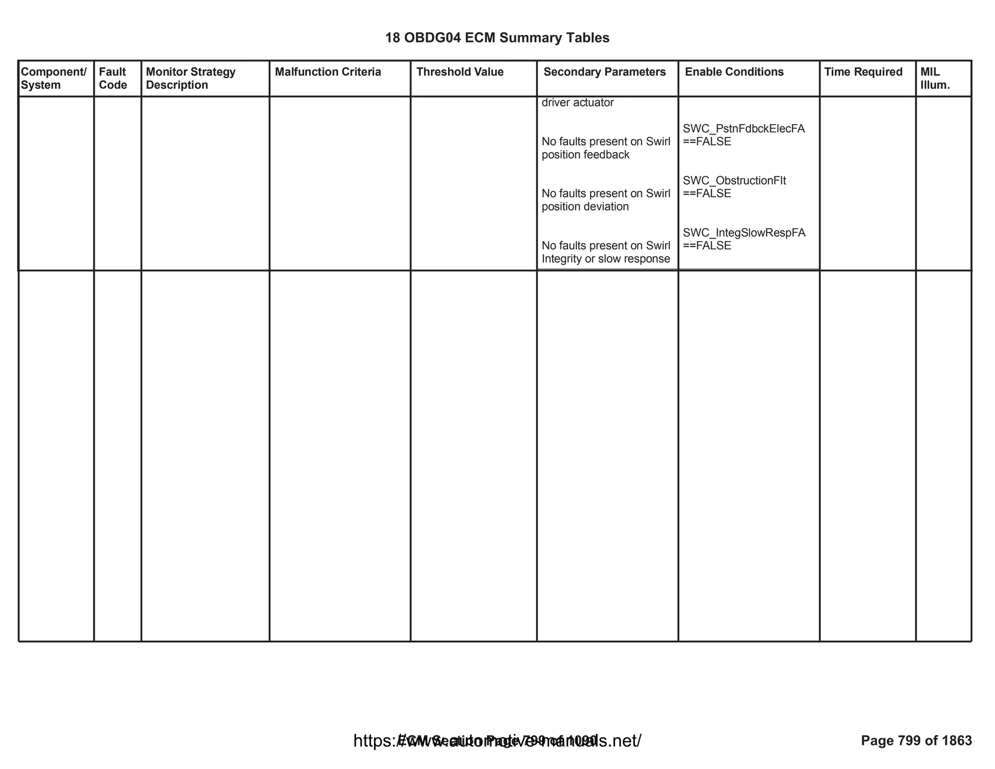
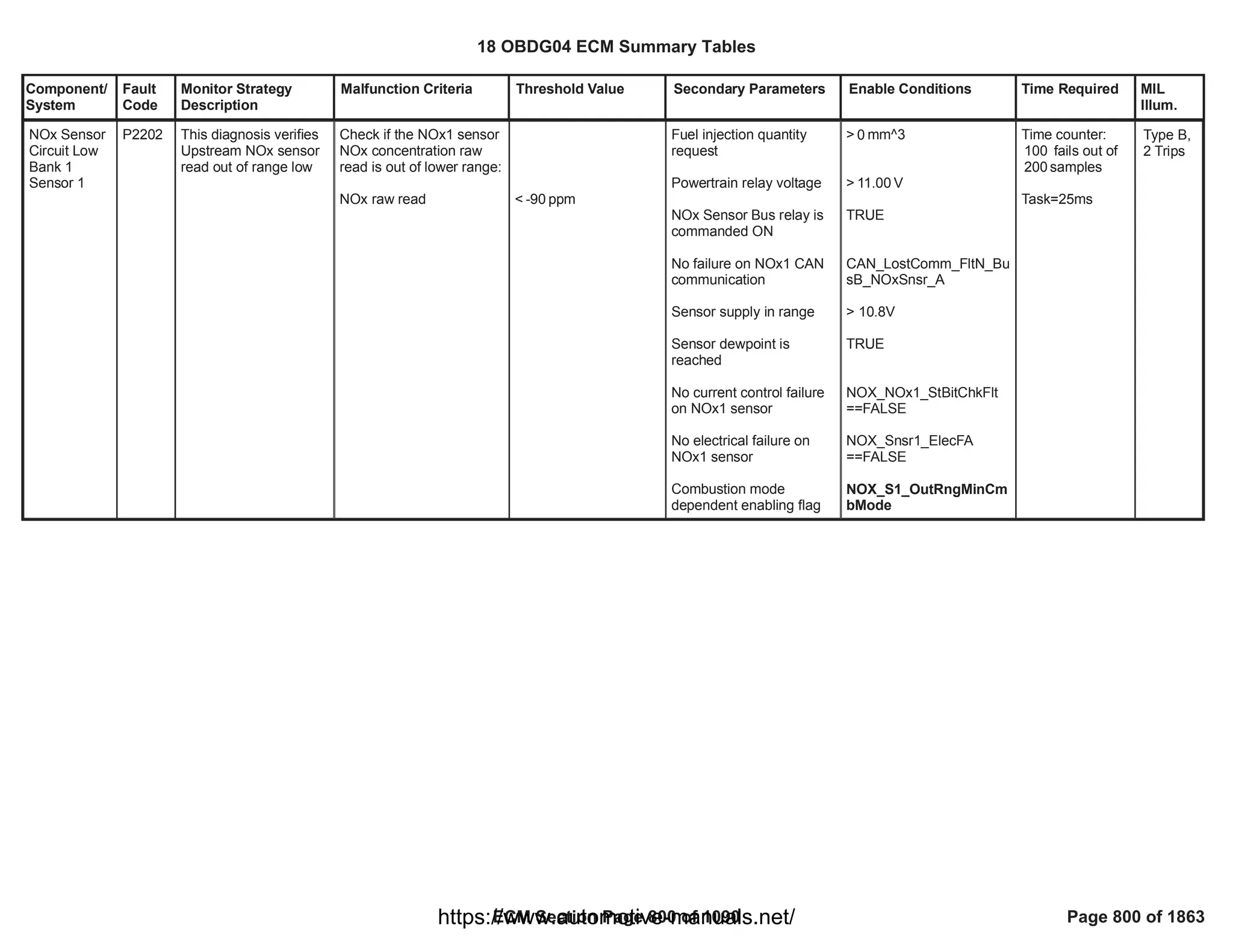
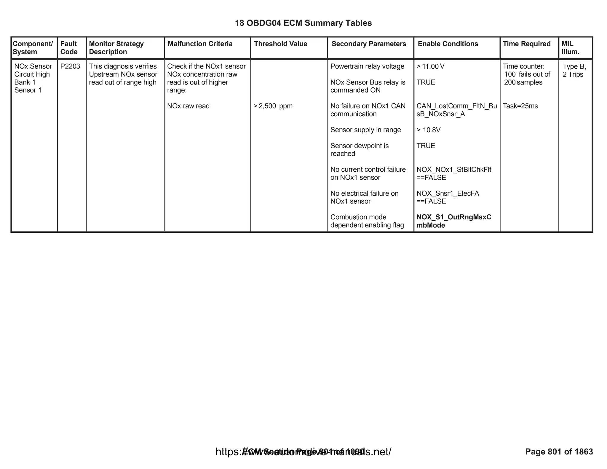


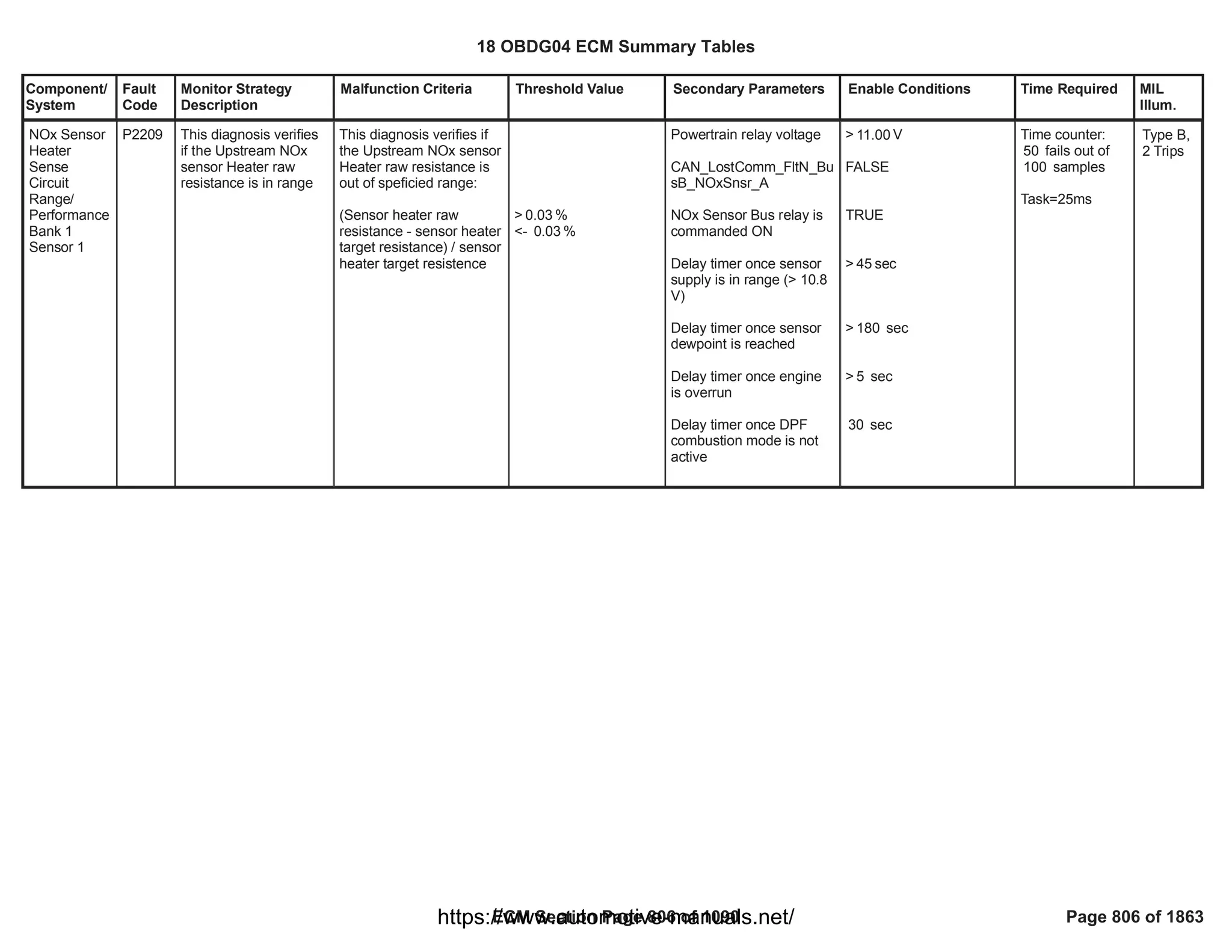
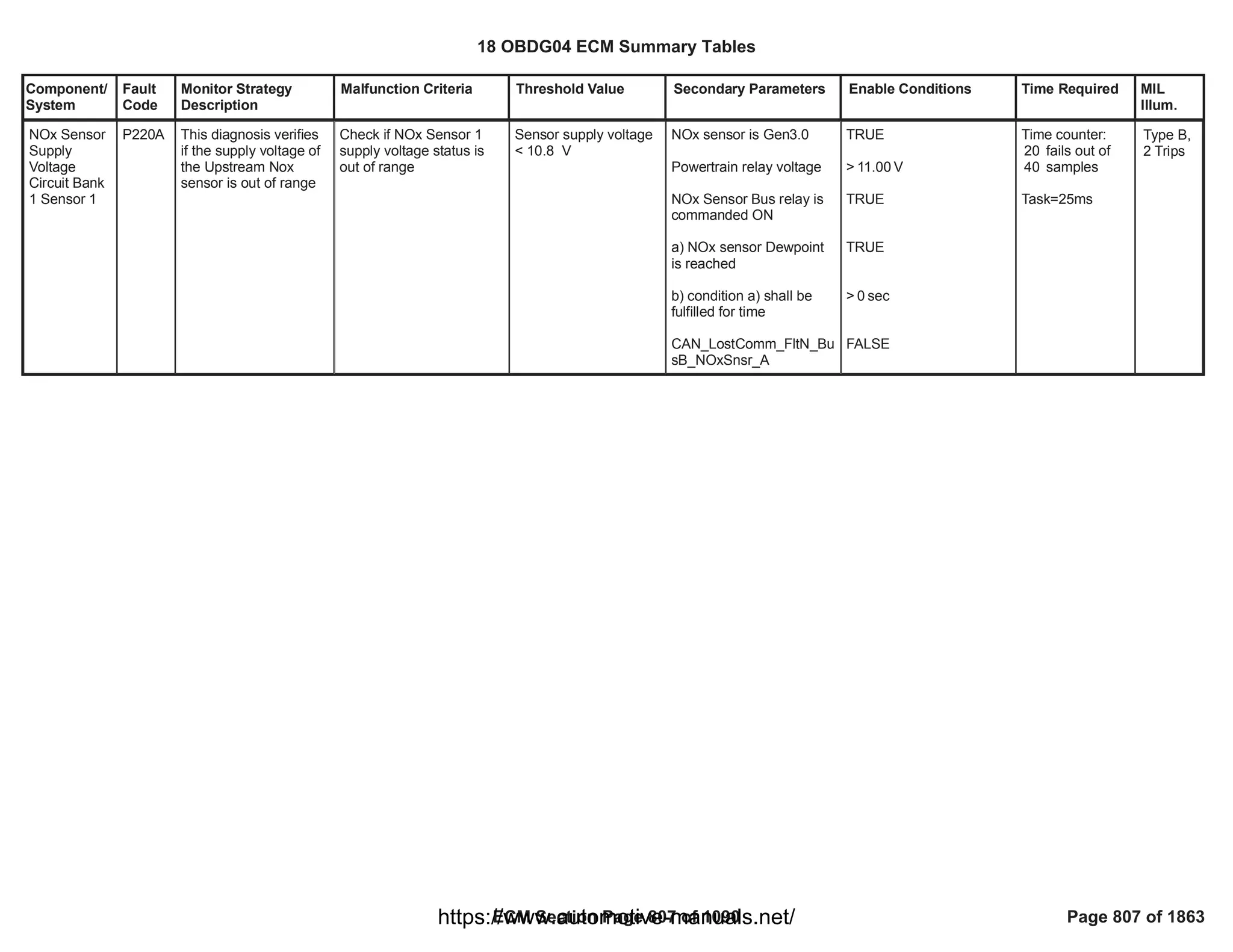
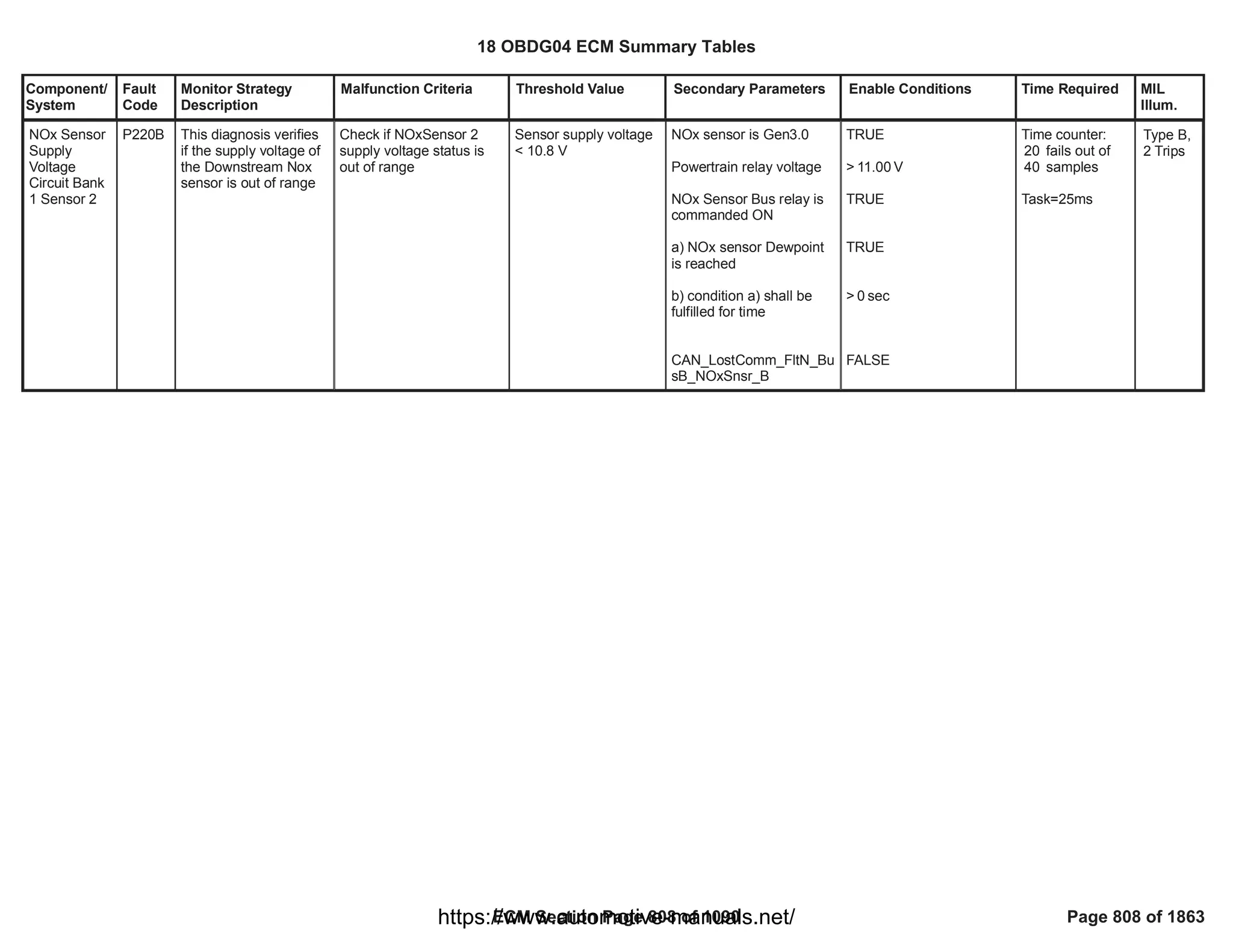
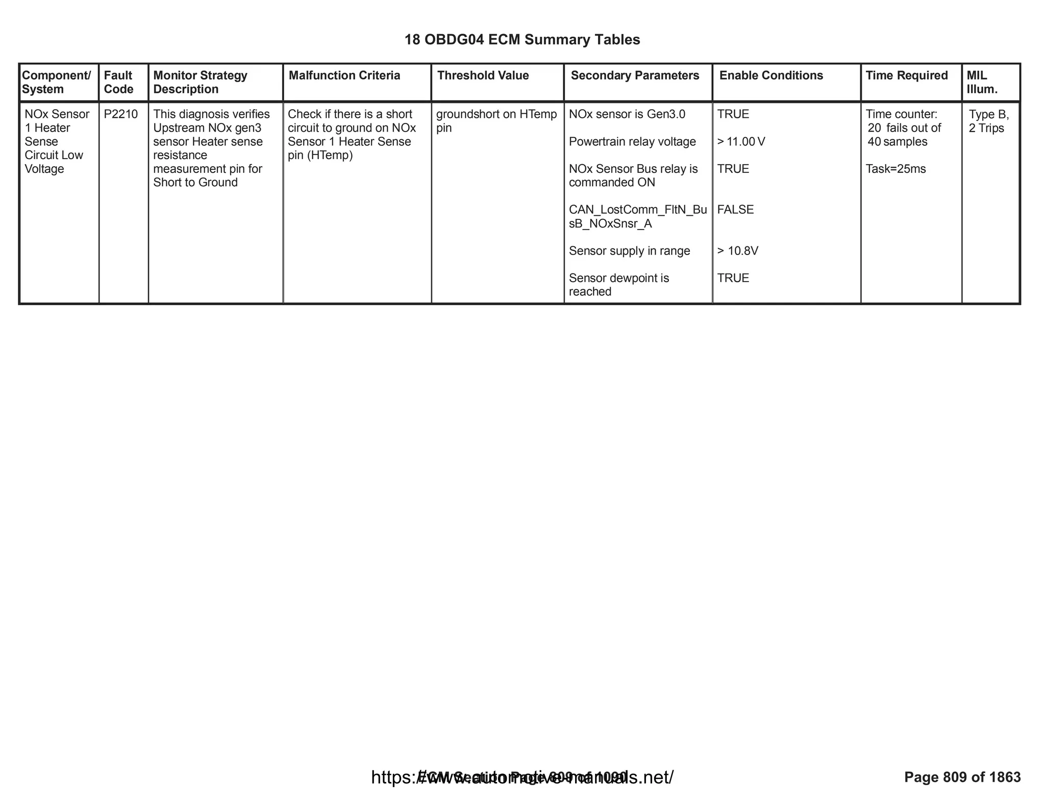
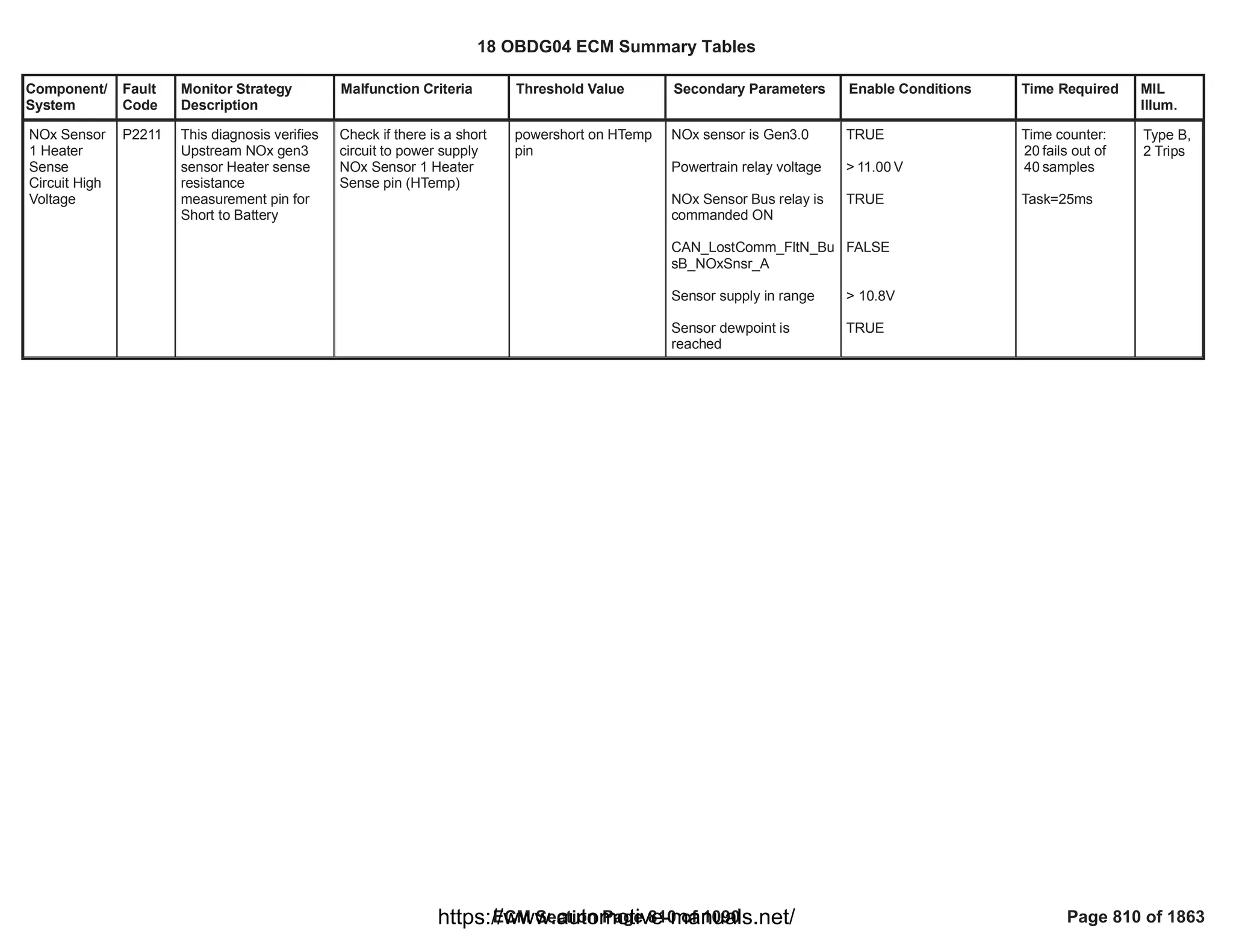
![Component/
System
Fault
Code
Monitor Strategy
Description
Malfunction Criteria Threshold Value Secondary Parameters Enable Conditions Time Required MIL
Illum.
O2 Sensor
Out of
Range
During
Deceleration
Bank 1
Sensor 1
P2297 This DTC aims to
detect a drift of
measured O2 value (A)
from an estimated
concentration (B) when
the latter can be
considered stable
during fuel cut-off
condition.
EWMA filtered error (A -
B) in overrun
condition is out of
plausible range
> [%]
4.00
< [%]
-6.00
Engine running
System voltage in range
Sensor is fully operative
No SQA learning is active
Enabled in combustion
mode
No Exhaust Brake active
i.e. intake manifold
pressure
No pending or confirmed
DTCs
> [V]
11.00
OXY_NOx1_O2_RawNot
Rlb
== FALSE
FAD_SQA_LrnET_Enbl
== FALSE
refer to supporting table
(
KaOXYD_b_NOx1OvrnC
hkCmbModeEnbl
)
< [kPa]
300.00
NOX_Snsr1_NotVld
NOX_Snsr1_PresFlt
OXY_O2_NOx1PlausMdl
Flt
OXY_NOx1SignRngChkFl
t
FHP_InjLeakageFA
EGR_PstnShtOffReqFA
(MAF_MAF_SnsrFA
AND
)
MAF_MAF_SnsrTFTKO
(MAP_SensorFA
AND
Once per trip
Note: if EWMA
Fast Initial
Response is
active OR
EWMA Rapid
Response is
active than
multiple tests per
trip are allowed.
Type B,
2 Trips
18 OBDG04 ECM Summary Tables
ECM Section Page 811 of 1090 Page 811 of 1863
https://www.automotive-manuals.net/](https://image.slidesharecdn.com/gmcenginefaultcodesdtc1-230327071418-56d3c5bb/75/18-OBDG04-ECM-Summary-Tables-811-2048.jpg)
![Component/
System
Fault
Code
Monitor Strategy
Description
Malfunction Criteria Threshold Value Secondary Parameters Enable Conditions Time Required MIL
Illum.
Stable fuel cut-off
condition has been
reached i.e. following
conditions are met for a
calibrateable time:
a. Engine speed in
operating range
b. EGR position
c. No fuel injected
d. Air mass per cylinder in
operating range
Estimated O2
concentration stable i.e.
difference between initial
and actual value
Air mass flown since fuel
cut-off condition
)
MAP_SensorTFTKO
> [s]
2.00
> [rpm]
1,100
< [rpm]
3,000
< [%]
60.00
> [mg]
75.00
< [mg]
1,500.00
< [%]
0.50
> [g]
20.00
18 OBDG04 ECM Summary Tables
ECM Section Page 812 of 1090 Page 812 of 1863
https://www.automotive-manuals.net/](https://image.slidesharecdn.com/gmcenginefaultcodesdtc1-230327071418-56d3c5bb/75/18-OBDG04-ECM-Summary-Tables-812-2048.jpg)
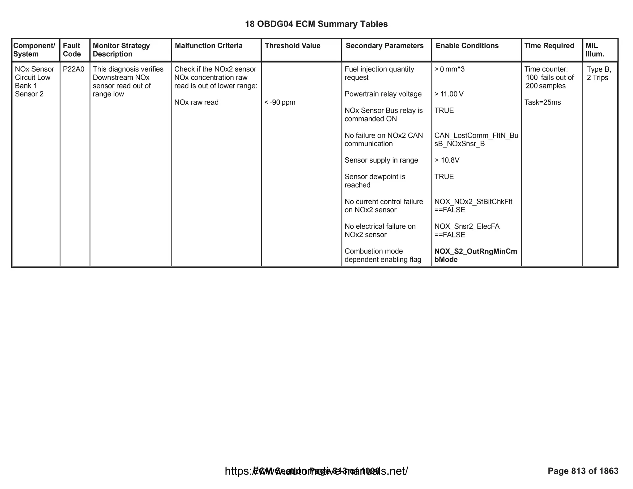
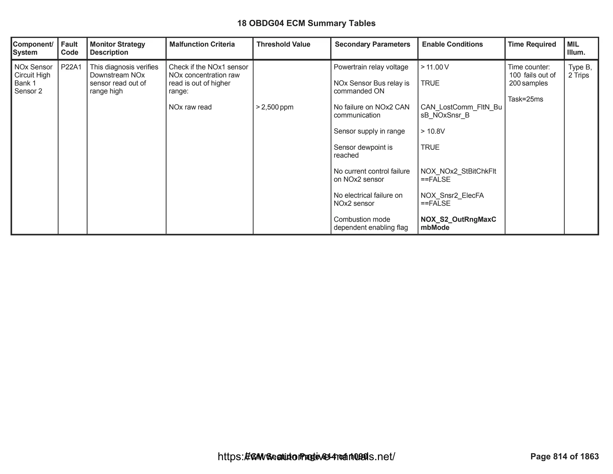
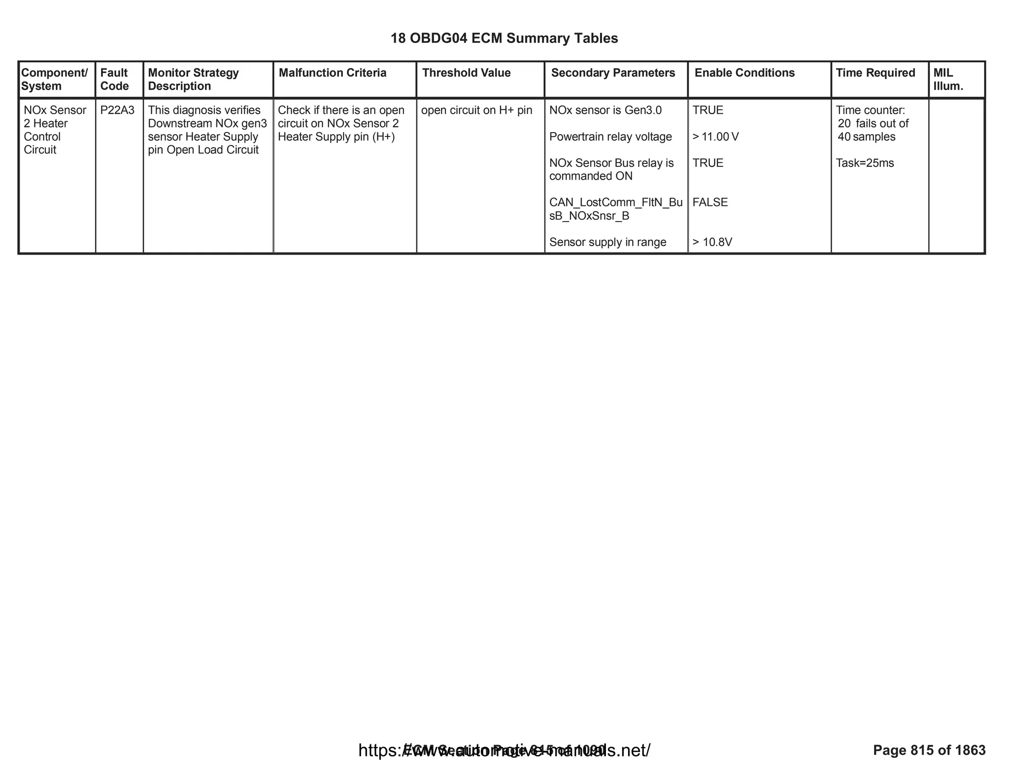


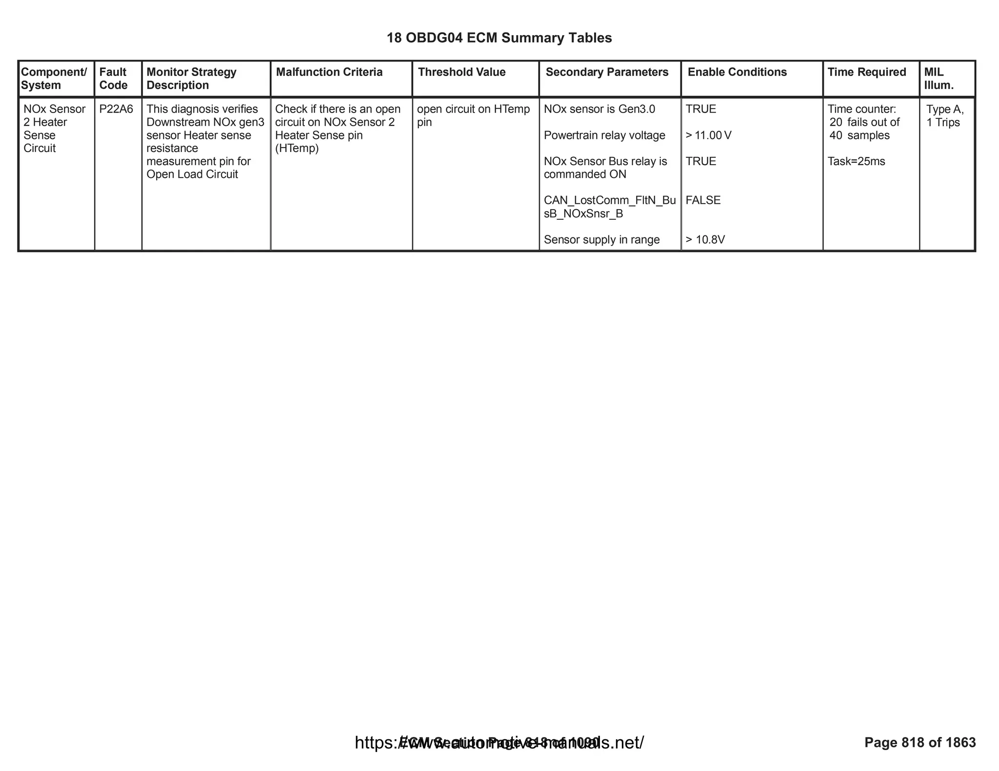
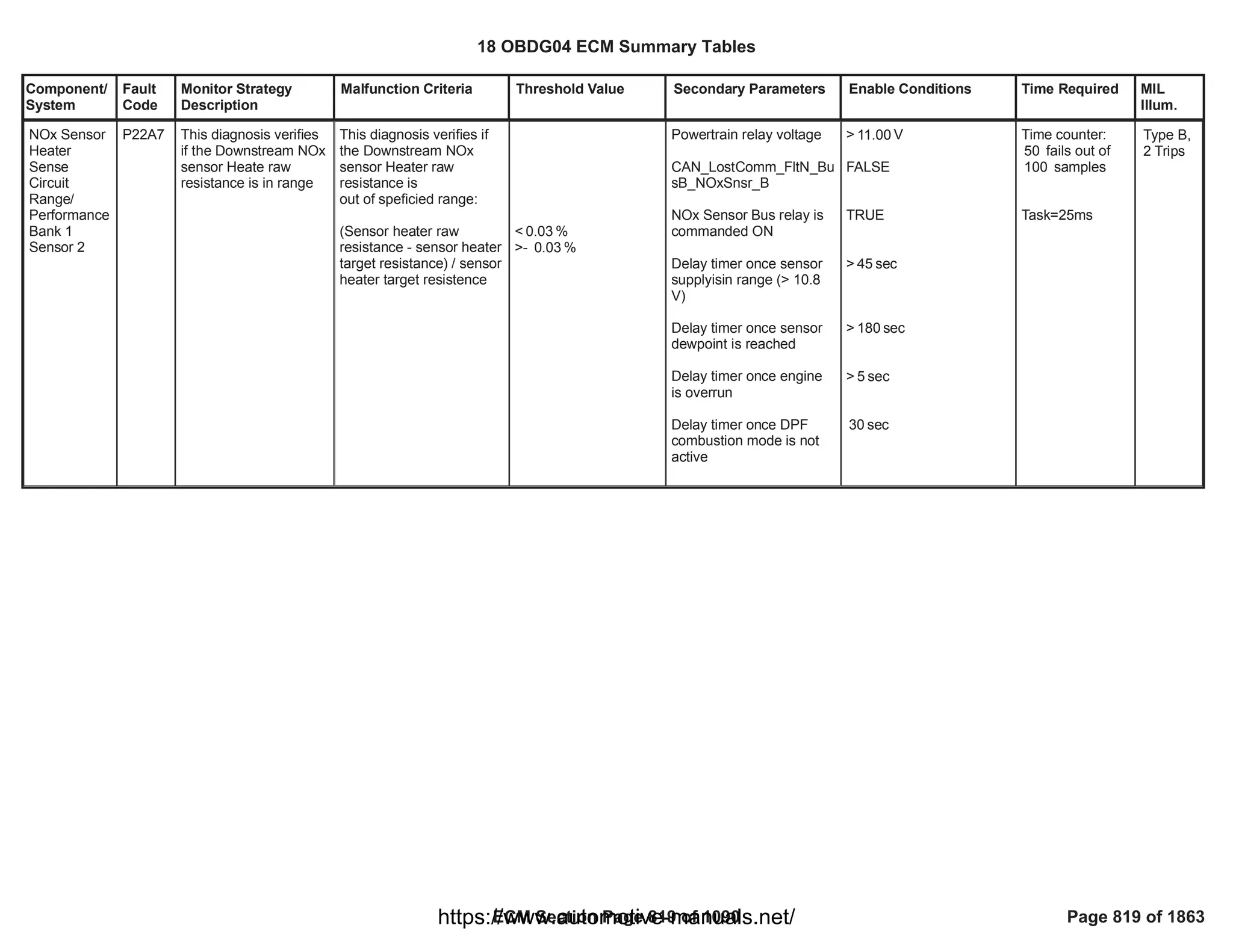
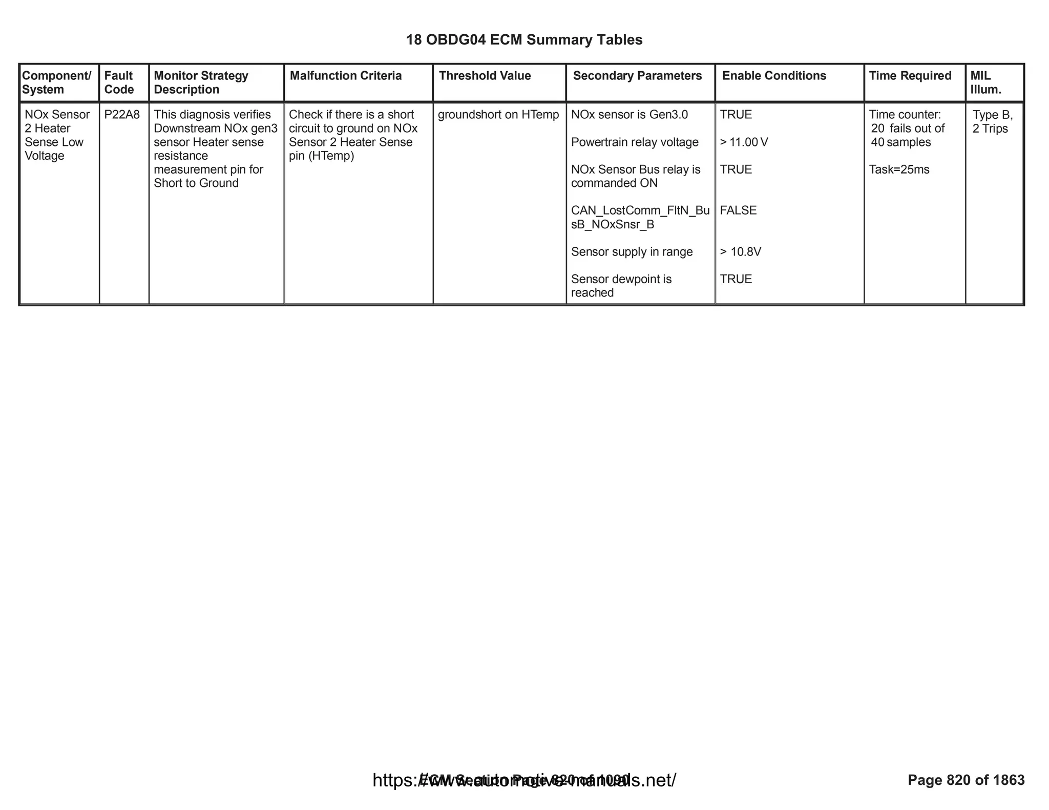
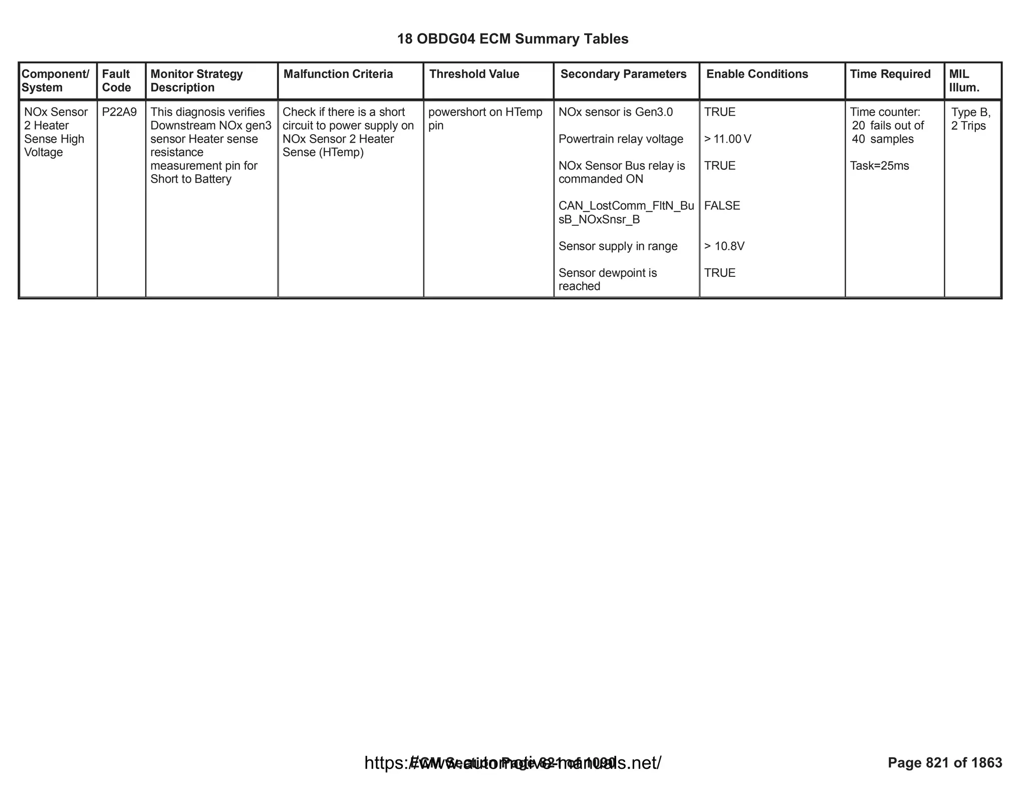
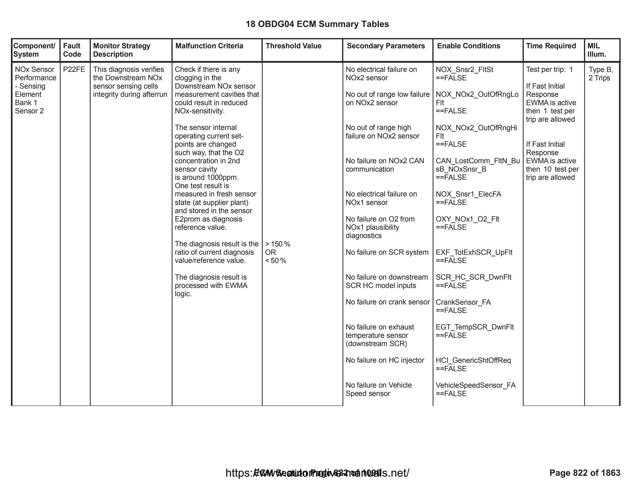
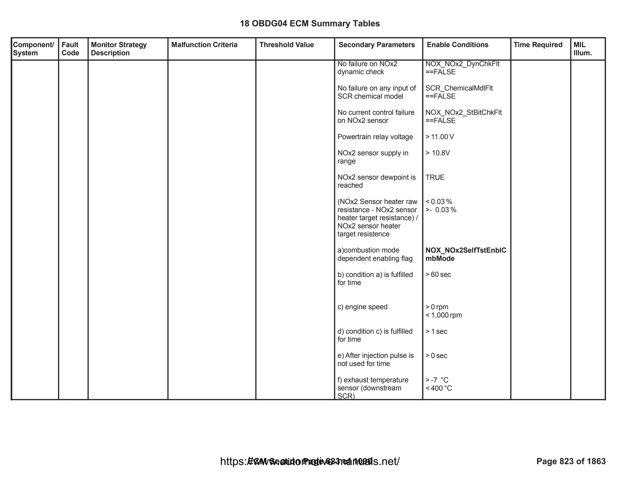
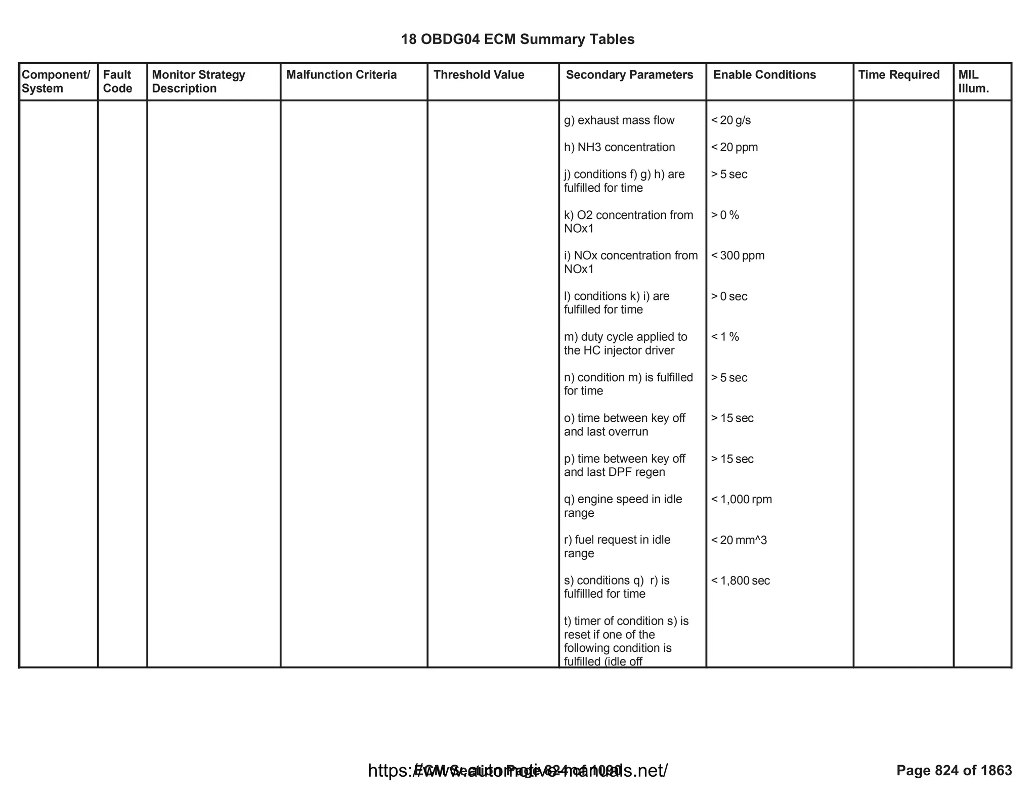
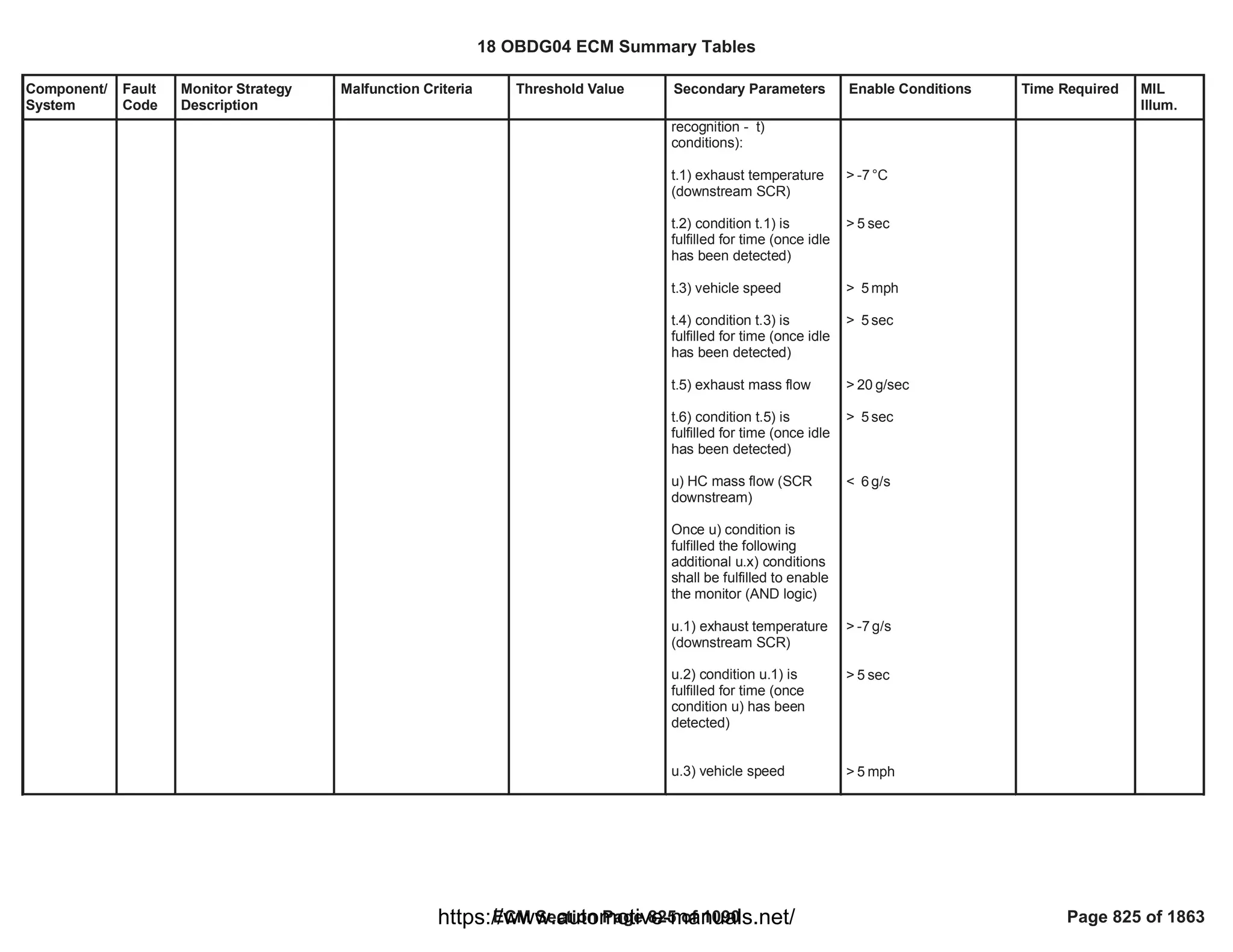
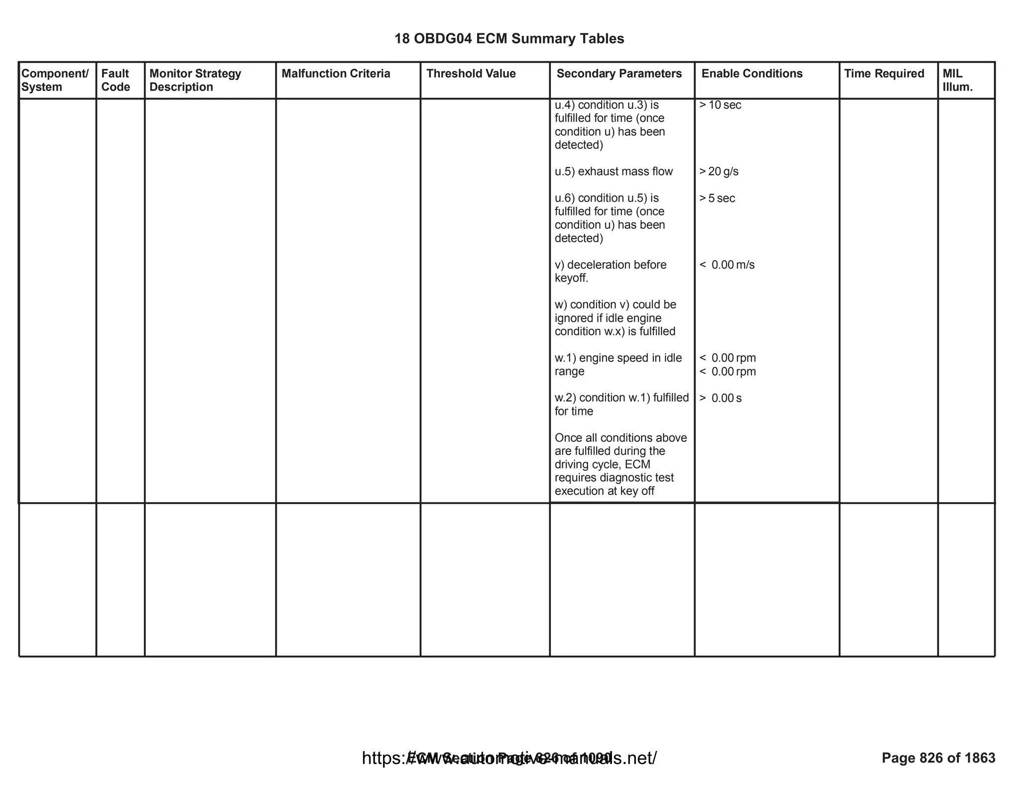
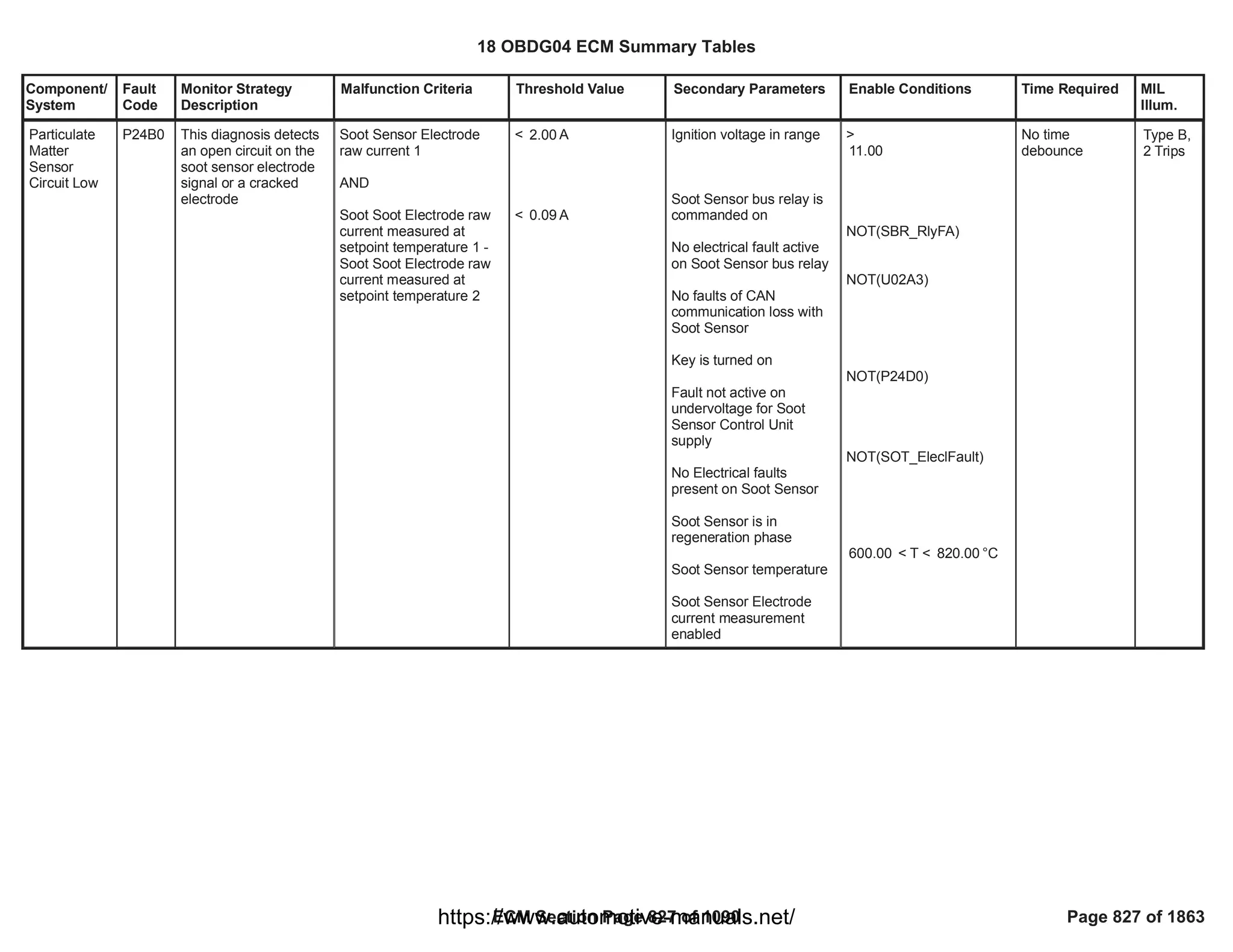
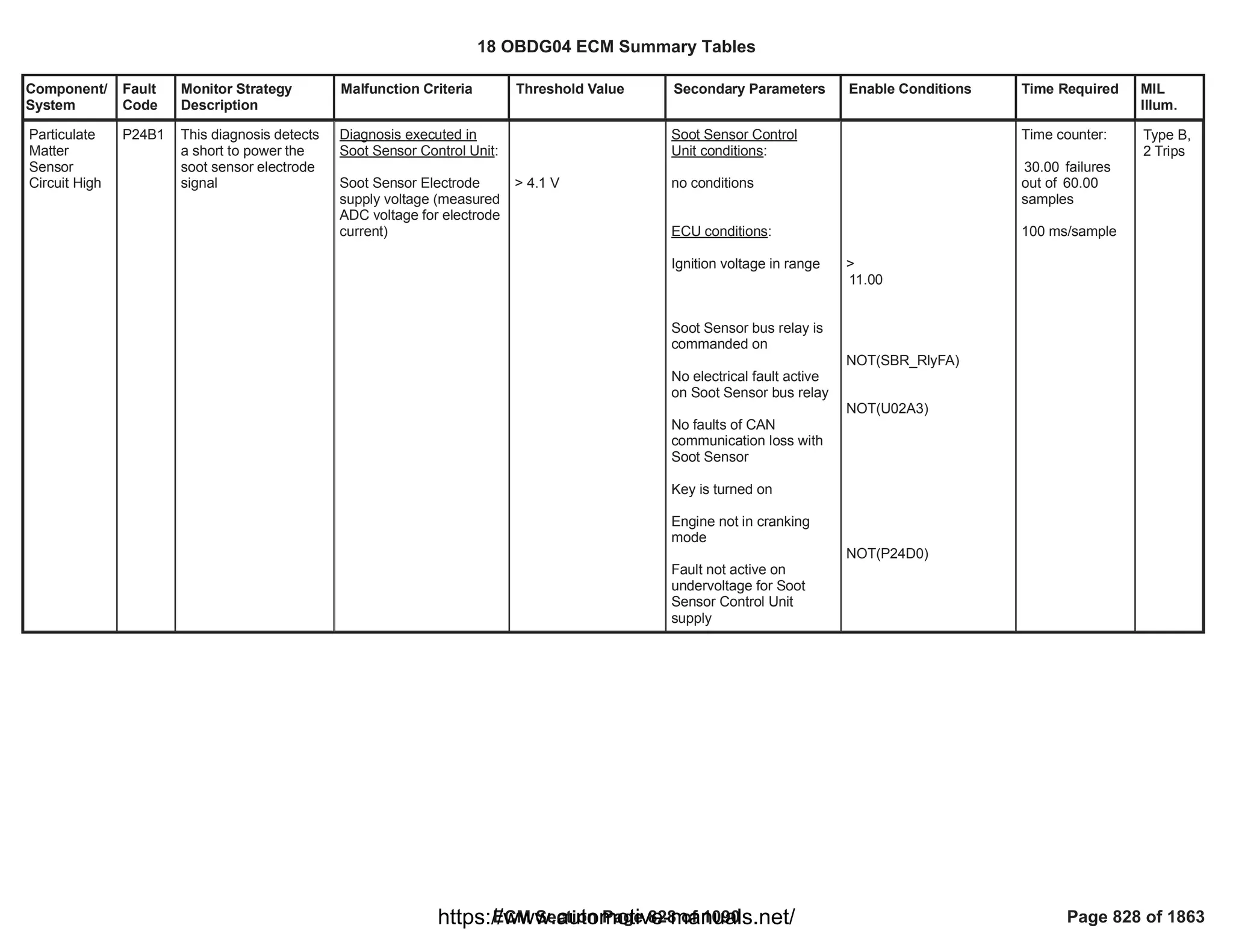
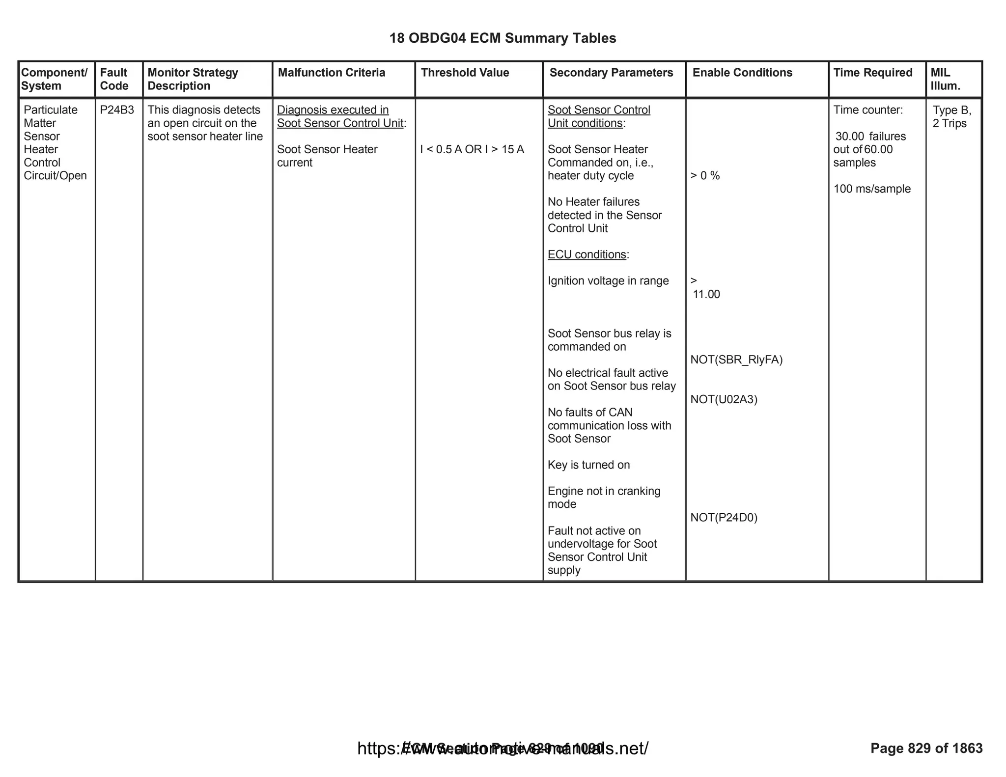
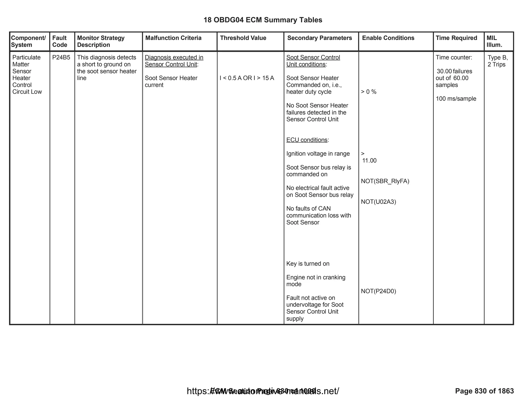
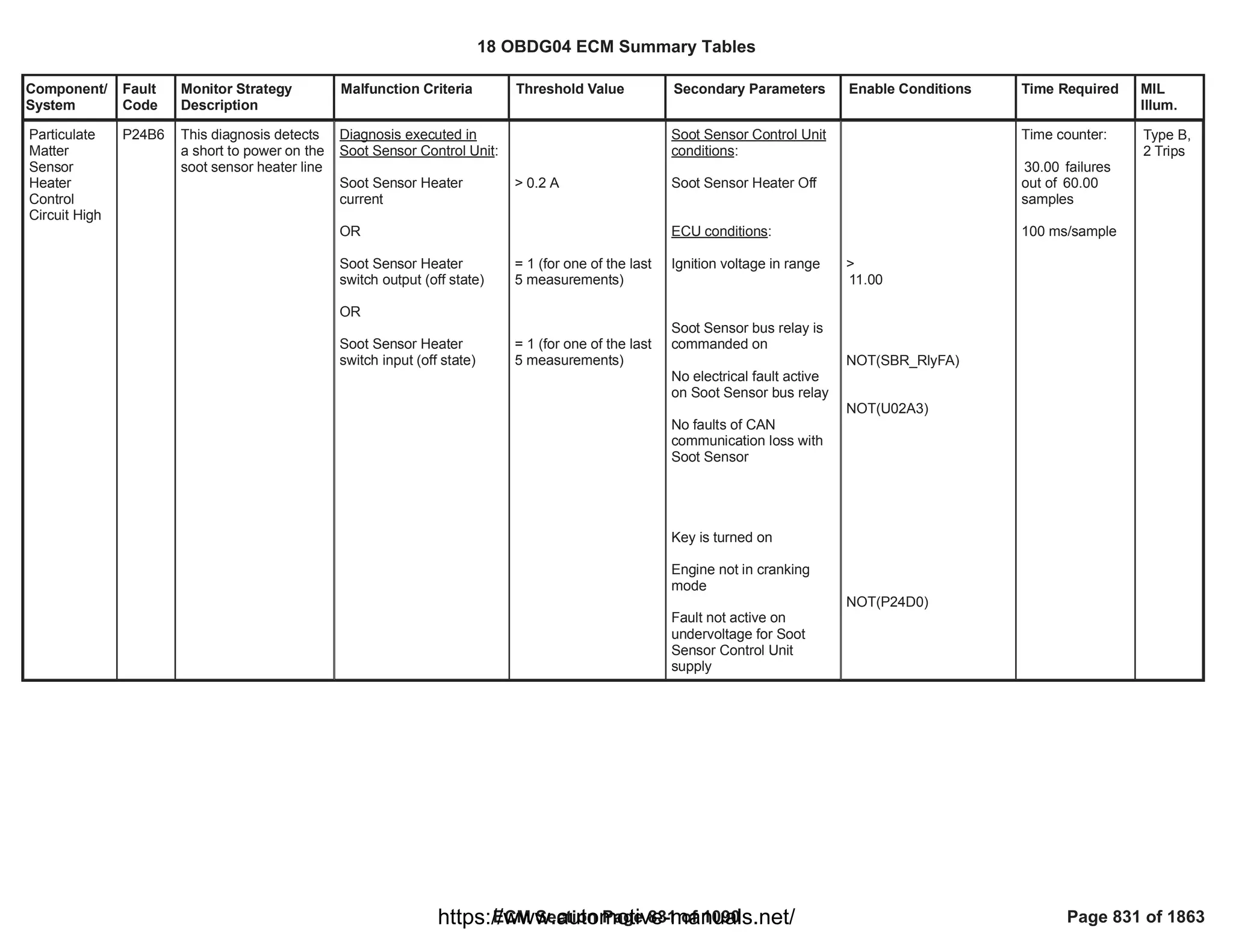
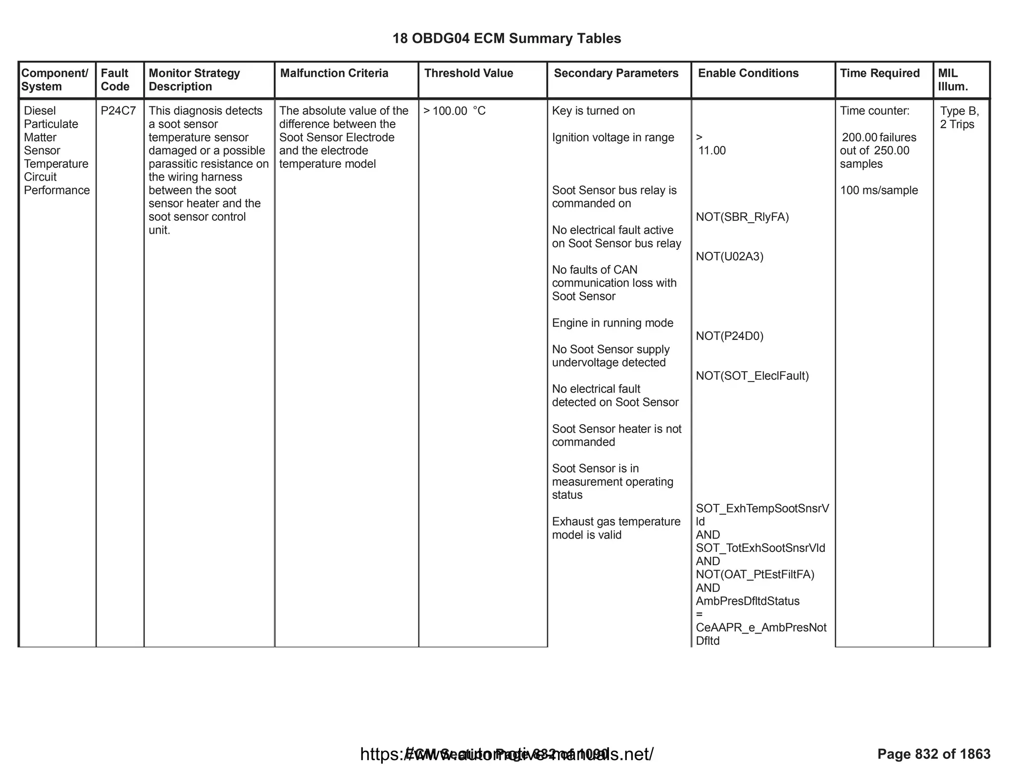
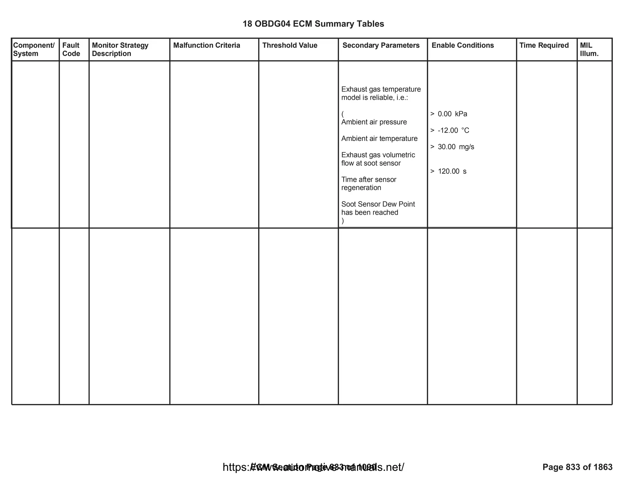
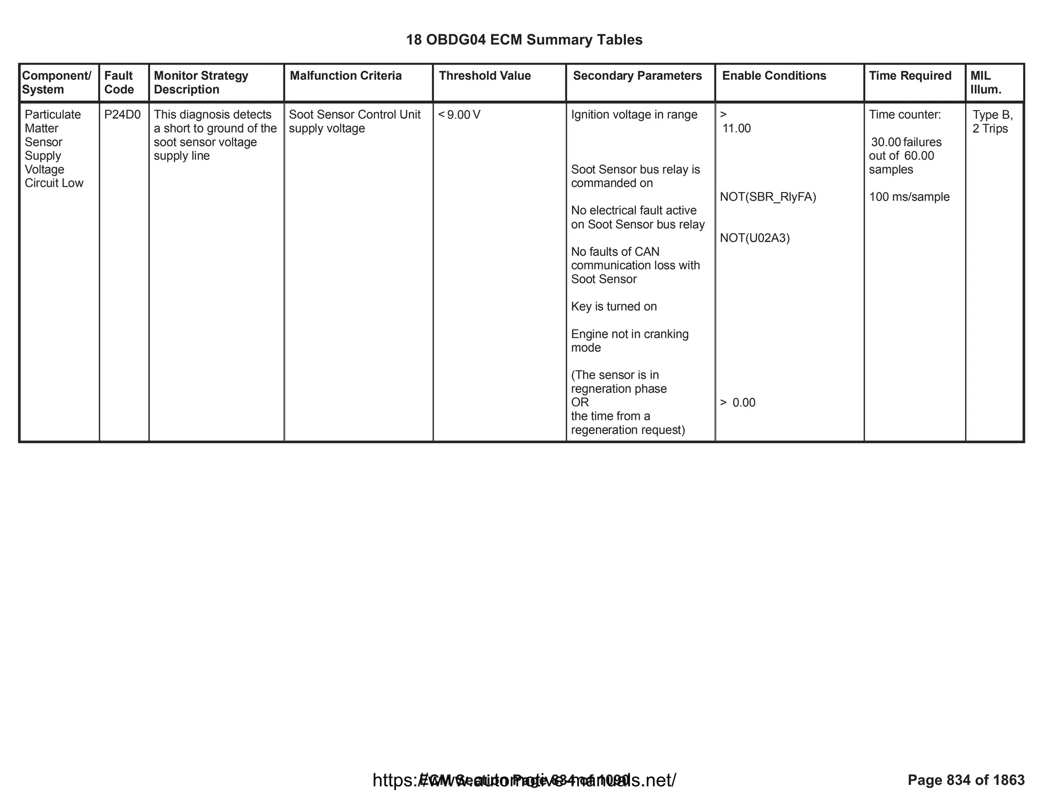
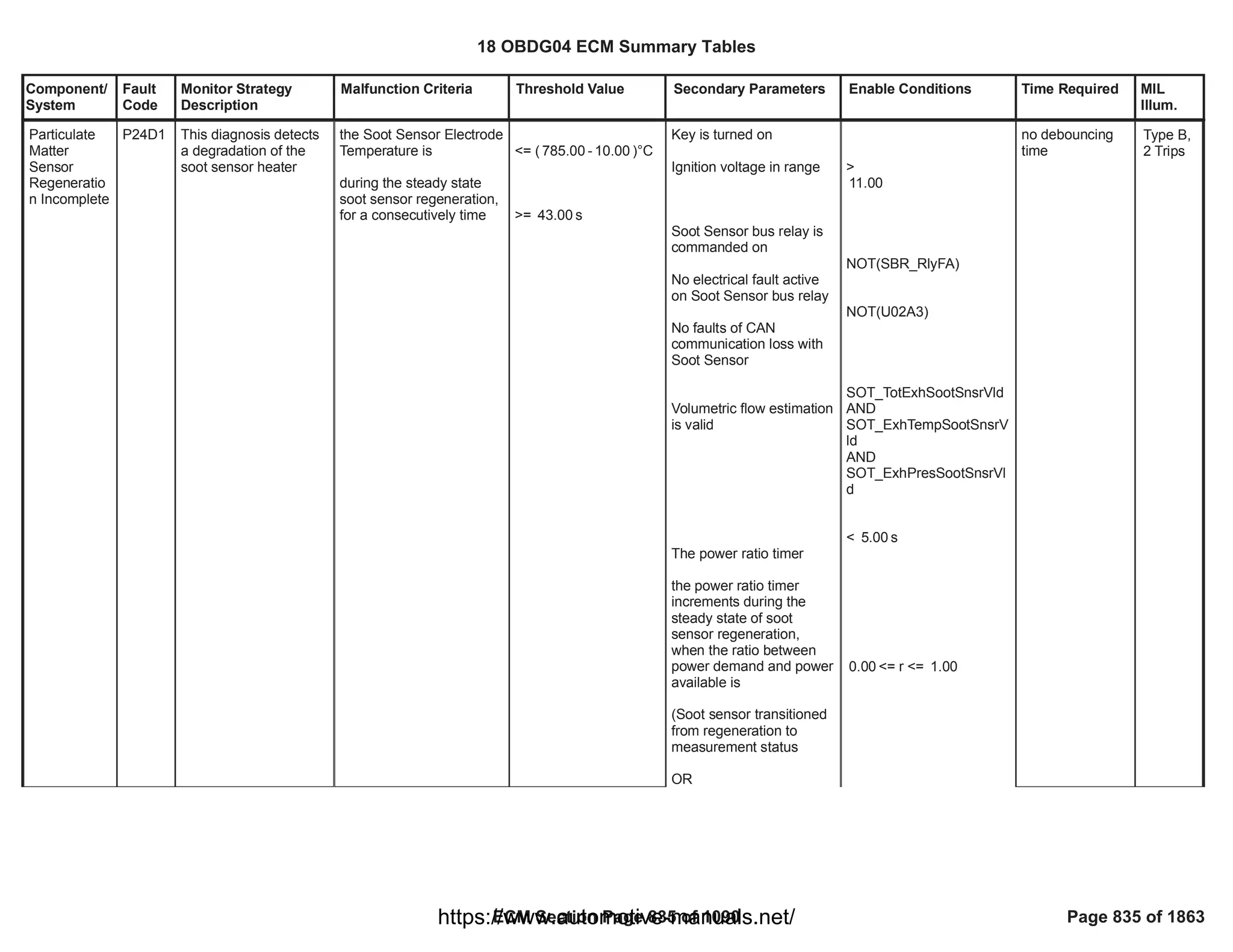
![Component/
System
Fault
Code
Monitor Strategy
Description
Malfunction Criteria Threshold Value Secondary Parameters Enable Conditions Time Required MIL
Illum.
Turbocharge
r VGT A
Position
Sensor
Circuit Low
(analog
position
sensor)
P2564 This monitor checks if
the VGT analog
position sensor is out of
electrical range low
analog position raw
voltage < low threshold
< [%]
5.00 Test enabled by
calibration
System out of the
cranking phase
Run Crank relay supply
voltage in range
Run crank active
== 1.00
> [V]
11.00
200.00
fail counts out of
250.00
sample counts
Function task:
6.25 ms
Type A,
1 Trips
18 OBDG04 ECM Summary Tables
ECM Section Page 837 of 1090 Page 837 of 1863
https://www.automotive-manuals.net/](https://image.slidesharecdn.com/gmcenginefaultcodesdtc1-230327071418-56d3c5bb/75/18-OBDG04-ECM-Summary-Tables-837-2048.jpg)
![Component/
System
Fault
Code
Monitor Strategy
Description
Malfunction Criteria Threshold Value Secondary Parameters Enable Conditions Time Required MIL
Illum.
Turbocharge
r VGT A
Position
Sensor
Circuit High
(analog
position
sensor)
P2565 This monitor checks if
the VGT analog
position sensor is out of
electrical range high
analog position raw
voltage > high threshold
> [%]
95.00 Test enabled by
calibration
System out of the
cranking phase
Run Crank relay supply
voltage in range
Run crank active
== 1.00
> [V]
11.00
200.00
fail counts out of
250.00
sample counts
Function task:
6.25 ms
Type A,
1 Trips
18 OBDG04 ECM Summary Tables
ECM Section Page 838 of 1090 Page 838 of 1863
https://www.automotive-manuals.net/](https://image.slidesharecdn.com/gmcenginefaultcodesdtc1-230327071418-56d3c5bb/75/18-OBDG04-ECM-Summary-Tables-838-2048.jpg)
![Component/
System
Fault
Code
Monitor Strategy
Description
Malfunction Criteria Threshold Value Secondary Parameters Enable Conditions Time Required MIL
Illum.
Turbocharge
r VGT A
Stuck
Closed (VGT
Vacuum)
P2599 This monitor detects
the VGT vanes
mechanically stuck in a
certain position
different from their
defaulted position (fully
open) when the
actuator is no longer
driven (missing
defaulted position)
Measured VGT position >
maximum threshold
> [%]
15.00 P0046 is already set
Waiting time after driver
shut off > minimum
threshold (needed for the
spring to drive the valve in
its defaulted position)
Diagnostic system
enabled (no clear code or
EOT in progress)
VGT position closed loop
control active (no faults
present on
VGT position sensor, VGT
vanes, VGT position
control deviation)
> [s]
4.00
VGT_PstnSnsrFA
==FALSE
==FALSE
VGT_ActCktFA
VGT_PstnCntrlFA
==FALSE
No debounce is
present: DTC
sets as soon as
the error is
present
Function task:
6.25 ms
Type A,
1 Trips
18 OBDG04 ECM Summary Tables
ECM Section Page 839 of 1090 Page 839 of 1863
https://www.automotive-manuals.net/](https://image.slidesharecdn.com/gmcenginefaultcodesdtc1-230327071418-56d3c5bb/75/18-OBDG04-ECM-Summary-Tables-839-2048.jpg)
![Component/
System
Fault
Code
Monitor Strategy
Description
Malfunction Criteria Threshold Value Secondary Parameters Enable Conditions Time Required MIL
Illum.
O2 Sensor
Pumping
Current Trim
Circuit Low
Bank 1
Sensor 1
P2627 This DTC detects if O2
signal is lower than
physical minimum
value or a Trim
Resistance pin open
load.
O2 signal lower than a
minimum value < [%]
-8.00
Engine running
System voltage in range
Sensor is fully operative
Enabled in combustion
mode
No pending or confirmed
DTC
> [V]
11.00
OXY_NOx1_O2_RawNot
Rlb
== FALSE
refer to supporting table
(
KaOXYD_b_NOx1SigRn
gEnblCmbMode
)
NOX_Snsr1_NotVld
Time counter:
failures out
200
of samples.
255
Time task 25[ms]
Type B,
2 Trips
18 OBDG04 ECM Summary Tables
ECM Section Page 840 of 1090 Page 840 of 1863
https://www.automotive-manuals.net/](https://image.slidesharecdn.com/gmcenginefaultcodesdtc1-230327071418-56d3c5bb/75/18-OBDG04-ECM-Summary-Tables-840-2048.jpg)
![Component/
System
Fault
Code
Monitor Strategy
Description
Malfunction Criteria Threshold Value Secondary Parameters Enable Conditions Time Required MIL
Illum.
O2 Sensor
Pumping
Current Trim
Circuit High
Bank 1
Sensor 1
P2628 This DTC detects if O2
signal is higher than
physical maximum
value or a Trim
Resistance pin open
load.
O2 signal higher than a
maximum value > [%]
27.00
Engine running
System voltage in range
Sensor is fully operative
Exhaust gas pressure
No Exhaust Brake active
i.e. intake manifold
pressure
No pending or confirmed
DTCs
> [V]
11.00
OXY_NOx1_O2_RawNot
Rlb
== FALSE
< [kPa]
300.00
< [kPa]
1,000.00
NOX_Snsr1_NotVld
NOX_Snsr1_PresFlt
(MAP_SensorFA
AND
)
MAP_SensorTFTKO
Time counter:
failures out
200
of samples.
255
Time task 25[ms]
Type B,
2 Trips
18 OBDG04 ECM Summary Tables
ECM Section Page 841 of 1090 Page 841 of 1863
https://www.automotive-manuals.net/](https://image.slidesharecdn.com/gmcenginefaultcodesdtc1-230327071418-56d3c5bb/75/18-OBDG04-ECM-Summary-Tables-841-2048.jpg)
![Component/
System
Fault
Code
Monitor Strategy
Description
Malfunction Criteria Threshold Value Secondary Parameters Enable Conditions Time Required MIL
Illum.
O2S Circuit
Range/
Performance
Bank 1
Sensor 1
P2A00 This DTC aims to
detect a drift of
measured O2 value (A)
from an estimated
concentration (B) when
the latter can be
considered stable
during full load
condition.
EWMA filtered error (A -
B) in full load condition is
out of plausible range
> [%]
6.00
< [%]
-6.00
Engine running
System voltage in range
Sensor is fully operative
Enabled in combustion
mode
(No After injection release
AND
Boolean Flag used to
enable After injection
status is TRUE)
No pending or confirmed
DTCs
Stable fuel cut-off
condition has been
reached i.e. following
> [V]
11.00
OXY_NOx1_O2_RawNot
Rlb
== FALSE
refer to supporting table
(
KaOXYD_b_NOx1LoadC
hkCmbModeEnbl
)
[boolean]
1
NOX_Snsr1_NotVld
NOX_Snsr1_PresFlt
OXY_NOx1SignRngChkFl
t
OXY_O2_NOx1PlausMdl
Flt
FHP_InjLeakageFA
(MAF_MAF_SnsrFA
AND
)
MAF_MAF_SnsrTFTKO
EGR_VlvTotFlowNotValid
Once per trip
Note: if EWMA
Fast Initial
Response is
active OR
EWMA Rapid
Response is
active than
multiple tests per
trip are allowed.
Type B,
2 Trips
18 OBDG04 ECM Summary Tables
ECM Section Page 842 of 1090 Page 842 of 1863
https://www.automotive-manuals.net/](https://image.slidesharecdn.com/gmcenginefaultcodesdtc1-230327071418-56d3c5bb/75/18-OBDG04-ECM-Summary-Tables-842-2048.jpg)
![Component/
System
Fault
Code
Monitor Strategy
Description
Malfunction Criteria Threshold Value Secondary Parameters Enable Conditions Time Required MIL
Illum.
conditions are met for a
calibrateable time:
a. Engine speed in
operating range
b. EGR mass flow
c. Injected fuel quantity in
operating range
d. Air mass per cylinder in
operating range
Estimated O2
concentration stable i.e.
difference between initial
and actual value
Air mass flown since fuel
cut-off condition
> [s]
2.00
> [rpm]
1,100
< [rpm]
3,000
< [mg]
1,000.00
> [mm^3]
30.00
< [mm^3]
80.00
> [mg]
500.00
< [mg]
1,500.00
< [%]
3.00
> [g]
20.00
18 OBDG04 ECM Summary Tables
ECM Section Page 843 of 1090 Page 843 of 1863
https://www.automotive-manuals.net/](https://image.slidesharecdn.com/gmcenginefaultcodesdtc1-230327071418-56d3c5bb/75/18-OBDG04-ECM-Summary-Tables-843-2048.jpg)
![Component/
System
Fault
Code
Monitor Strategy
Description
Malfunction Criteria Threshold Value Secondary Parameters Enable Conditions Time Required MIL
Illum.
O2 Sensor
Slow
Response -
Rich to Lean
Bank 1
Sensor 1
P014C This DTC checks if
oxygen value dynamic
is slower compared to
a functioning sensor.
Test is performed in
transitions from high
load to overrun.
Once generic enabling
conditions are met,
diagnosis waits for
engine operating point
stability (in terms of
engine speed and fuel
injected). When a
stable operating point
is reached for a
calibrated time and an
overrun condition is
detected, the delta
between the actual O2
value (a) and the one in
fresh air (b = 20.95 %)
is calculated.
Then two thresholds
are calculated as
percentage of the initial
delta:
O2_Thrsh1 = a + (b - a)
* 0.10
O2_Thrsh2 = a + (b - a)
* 0.40
Two timers are
incremented to
evaluate sensor
dynamic while O2
moves from O2 initial
value (a) to O2_Thrsh2
One of the following
conditions shall be true:
EWMA filtered O2 raising
time from O2 initial value
(a) to O2_Thrsh2
EWMA filtered O2 raising
time from O2_Thrsh1
value to O2_Thrsh2
> [s]
1.10
> [s]
0.80
Global Enabling
Condition
Engine running
System voltage in range
Sensor is fully operative
(No SQA learning is active
AND
Boolean Flag used to
enable SQA learning
active status is TRUE)
No Exhaust Brake active
i.e. intake manifold
pressure
Enabled in combustion
mode
No pending or confirmed
DTCs
> [V]
11.00
OXY_O2_NOx1_SDC_Crt
dNotRlb
== FALSE
FAD_SQA_LrnET_Enbl
== FALSE
[boolean]
1
< [kPa]
299.00
refer to supporting table
(
KaOXYD_b_NOx1_IncrD
ynChkCmbEnbl
)
NOX_Snsr1_NotVld
NOX_Snsr1_PresFlt
OXY_NOx1SignRngMinFl
t
OXY_NOx1SignRngMaxF
lt
OXY_NOx1ChkOvrrnFlt
OXY_NOx1ChkLoadFlt
FHP_InjLeakageFA
Once per trip
Note: if EWMA
Fast Initial
Response is
active OR
EWMA Rapid
Response is
active than
multiple tests per
trip are allowed.
Type B,
2 Trips
18 OBDG04 ECM Summary Tables
ECM Section Page 844 of 1090 Page 844 of 1863
https://www.automotive-manuals.net/](https://image.slidesharecdn.com/gmcenginefaultcodesdtc1-230327071418-56d3c5bb/75/18-OBDG04-ECM-Summary-Tables-844-2048.jpg)
![Component/
System
Fault
Code
Monitor Strategy
Description
Malfunction Criteria Threshold Value Secondary Parameters Enable Conditions Time Required MIL
Illum.
and from O2_Thrsh1 to
O2_Thrsh2. EWMA is
applied on both timers.
Additional enabling
conditions for
transitioning state
machine from stable
operation state to wait
overrun state:
Operating point reached
and stable
i.e. following conditions
are met for a time
a. Engine speed in
operating range
b. Injected fuel quantity in
operating range
c. Fuel variation
Additional enabling
conditions for
transitioning state
machine from wait
overrun state to timer
evaluation state:
Injected fuel quantity goes
to
in a time
Additional enabling
conditions when in
(MAF_MAF_SnsrFA
AND
)
MAF_MAF_SnsrTFTKO
EGR_PstnShtOffReqFA
(MAP_SensorFA
AND
)
MAP_SensorTFTKO
> [s]
3.00
> [rpm]
1,500
< [rpm]
3,000
> [mm^3]
15
< [mm^3]
70
< [mm^3]
2.00
= 0 [mm^3]
< [s]
2.50
18 OBDG04 ECM Summary Tables
ECM Section Page 845 of 1090 Page 845 of 1863
https://www.automotive-manuals.net/](https://image.slidesharecdn.com/gmcenginefaultcodesdtc1-230327071418-56d3c5bb/75/18-OBDG04-ECM-Summary-Tables-845-2048.jpg)
![Component/
System
Fault
Code
Monitor Strategy
Description
Malfunction Criteria Threshold Value Secondary Parameters Enable Conditions Time Required MIL
Illum.
timer evaluation state:
EGR position < [%]
100
18 OBDG04 ECM Summary Tables
ECM Section Page 846 of 1090 Page 846 of 1863
https://www.automotive-manuals.net/](https://image.slidesharecdn.com/gmcenginefaultcodesdtc1-230327071418-56d3c5bb/75/18-OBDG04-ECM-Summary-Tables-846-2048.jpg)
![Component/
System
Fault
Code
Monitor Strategy
Description
Malfunction Criteria Threshold Value Secondary Parameters Enable Conditions Time Required MIL
Illum.
O2 Sensor
Slow
Response -
Lean to Rich
Bank 1
Sensor 1
P014D This DTC checks if
oxygen value dynamic
is slower compared to
a functioning sensor.
Test is performed in
transitions from overrun
to high load.
Once generic enabling
conditions are met,
diagnosis waits for an
overrun stable
condition. After that a
fuel increase is
detected within a
calibrated time.
Different timers are
updated:
- Timer_1 is
incremented when
O2Model < [%]
19.00
AND O2 > [%]
19.00
- Timer_2 is
incremented when
O2Model < [%]
19.00
AND O2 < [%]
19.00
- Timer_3 is
incremented when
O2Model < [%]
19.00
AND O2Model > 15.00
[%]
- Timer_4 is
incremented when
O2Model < [%]
19.00
AND O2Model > 12.00
[%]
- Timer_5 is
incremented when
O2Model < [%]
19.00
O2Model is based on
One of the following
conditions shall be true:
EWMA filtered Timer_1
EWMA filtered
Timer_error
> [s]
0.92
> [-]
2.00
Global Enabling
Condition
Engine running
System voltage in range
Sensor is fully operative
No SQA learning is active
AND
Boolean Flag used to
enable SQA learning
check is TRUE
Enabled in combustion
mode
No pending or confirmed
DTCs
> [V]
11.00
OXY_O2_NOx1_SDC_Crt
dNotRlb
== FALSE
FAD_SQA_LrnET_Enbl
== FALSE
[boolean]
1
refer to supporting table
(
KaOXYD_b_NOx1_Decr
DynChkCmbEnbl
)
NOX_Snsr1_NotVld
OXY_NOx1SignRngMinFl
t
OXY_NOx1SignRngMaxF
lt
OXY_NOx1ChkOvrrnFlt
OXY_NOx1ChkLoadFlt
FHP_InjLeakageFA
(MAF_MAF_SnsrFA
AND
)
MAF_MAF_SnsrTFTKO
EGR_PstnShtOffReqFA
Once per trip
Note: if EWMA
Fast Initial
Response is
active OR
EWMA Rapid
Response is
active than
multiple tests per
trip are allowed.
Type A,
1 Trips
18 OBDG04 ECM Summary Tables
ECM Section Page 847 of 1090 Page 847 of 1863
https://www.automotive-manuals.net/](https://image.slidesharecdn.com/gmcenginefaultcodesdtc1-230327071418-56d3c5bb/75/18-OBDG04-ECM-Summary-Tables-847-2048.jpg)
![Component/
System
Fault
Code
Monitor Strategy
Description
Malfunction Criteria Threshold Value Secondary Parameters Enable Conditions Time Required MIL
Illum.
injected fuel quantity
and air mass.
Test ends when one of
the following condition
is verified:
- O2 < [%]
15.00
- Timer_5 > [s]
10.00
- Timer_4 > [s]
0.79
After test end, all the
following condition shall
be verified to evaluate
test validity:
- Timer_4 < [s]
0.79
- O2Model < [%]
12.00
- Timer_3 < [s]
0.16
If test is valid:
Timer_error = (Timer_2
- Timer_3) / Timer_3 is
calculated and EWMA
is applied on Timer_1
and on Time_error.
Additional enabling
conditions for
transitioning state
machine from stable
operation state to wait
fuel injection state:
Operating point reached
and stable
i.e. following conditions
are met for a time
a. Engine speed in
operating range
b. Injected fuel quantity
Additional enabling
conditions for
transitioning state
machine from wait fuel
injection state to timer
evaluation state:
Injected fuel quantity
Additional enabling
conditions when in
timer evaluation state:
Injected fuel quantity
within a time
OXY_O2_NOx1PlausMdl
Flt
> [s]
1.00
> [rpm]
1,250
< [rpm]
3,000
< [mm^3]
1
> [mm^3]
1
> [mm^3]
20
< [s]
1.00
18 OBDG04 ECM Summary Tables
ECM Section Page 848 of 1090 Page 848 of 1863
https://www.automotive-manuals.net/](https://image.slidesharecdn.com/gmcenginefaultcodesdtc1-230327071418-56d3c5bb/75/18-OBDG04-ECM-Summary-Tables-848-2048.jpg)
![Component/
System
Fault
Code
Monitor Strategy
Description
Malfunction Criteria Threshold Value Secondary Parameters Enable Conditions Time Required MIL
Illum.
Turbocharge
r VGT A
Stuck Open
(Single and
Two stage
VGT DC
Motor)
P2598 This monitor checks if
the VGT vanes got
mechanically stuck in a
position more open
than what is required
by the control
position tracking error
(setpoint position -
measured position) >
positive threshold
>
P2598: Positive
Position Tracking
Error Threshold
[%]
Test enabled by
calibration
System out of the
cranking phase
PT relay supply voltage in
range
Position control in closed
loop (no faults present on
VGT position sensor, VGT
vanes, position deviation)
Position setpoint is in
steady state conditions
Engine speed > threshold
Engine coolant
temperature > threshold
Intake manifold
temperature > threshold
All previous conditions
must be verified for a
minimum calibratable time
== 1.00
> [V]
11.00
==
VGT_PstnSnsrFA
FALSE
VGT_ActCktFA
== FALSE
VGT_PstnCntrlFA
== FALSE
< [%/s]
40.00
> [%/s]
-40.00
> [rpm]
1,500.00
> [°C]
-7.00
> [°C]
-7.00
> [s]
0.50
640.00
fail counts out of
800.00
sample counts
Function task:
6.25 ms
Type A,
1 Trips
18 OBDG04 ECM Summary Tables
ECM Section Page 849 of 1090 Page 849 of 1863
https://www.automotive-manuals.net/](https://image.slidesharecdn.com/gmcenginefaultcodesdtc1-230327071418-56d3c5bb/75/18-OBDG04-ECM-Summary-Tables-849-2048.jpg)
![Component/
System
Fault
Code
Monitor Strategy
Description
Malfunction Criteria Threshold Value Secondary Parameters Enable Conditions Time Required MIL
Illum.
Turbocharge
r VGT A
Position
Exceeded
Learning
Limit (VGT
Smart)
P003A This monitor checks if
the VGT smart travel
(from fully closed to
fully open position)
measured at key off
during the learning
procedure is plausibile
physical travel measured
at key off <
low threshold
OR
physical travel measured
at key off >
high threshold
< [counts]
0.00
OR
> [counts]
0.00
Test enabled by
calibration
Key signal is off
Learning procedure at key
off has been successfully
completed:
- ambient temperature
greater than a threshold;
- engine coolant
temperature in range;
- battery voltage in range;
-learning time needed
smaller than a time out
threshold;
- no faults present on
coolant temperature
sensor;
- no faults present on
ambient temperature
sensor.
End Of Trip event has
elapsed
No fault validated on
smart VGT rolling
counters
== 1.00
>= (°C)
100.00
<= (°C)
0.00
>= (°C)
100.00
<= (V)
0.00
>= (V)
20.00
<= (s)
0.00
ECT_Sensor_FA
==FALSE
OAT_PtEstFiltFA
==FALSE
CFM_VGT_CommFA
==FALSE
No debounce is
present: DTC
sets as soon as
the error is
present
Function task:
at key off
Type A,
1 Trips
18 OBDG04 ECM Summary Tables
ECM Section Page 850 of 1090 Page 850 of 1863
https://www.automotive-manuals.net/](https://image.slidesharecdn.com/gmcenginefaultcodesdtc1-230327071418-56d3c5bb/75/18-OBDG04-ECM-Summary-Tables-850-2048.jpg)
![Component/
System
Fault
Code
Monitor Strategy
Description
Malfunction Criteria Threshold Value Secondary Parameters Enable Conditions Time Required MIL
Illum.
Turbocharge
r VGT A
Performance
(VGT Smart)
P0046 This monitor detects an
obstruction on the
actuator (obstruction
found during the vanes
opening or closing)
checking the setpoint
position against the
position measured by
the VGT Position
Sensor
|VGT Position Tracking
Error| (setpoint position -
measured position) >
maximum threshold
> [%]
0.00 Test enabled by
calibration
Diagnostic system
enabled (no clear code or
EOT in progress)
System out of the
cranking phase
PT relay supply voltage in
range
VGT position closed loop
control active (no faults
present on
VGT position sensor, VGT
vanes, VGT position
control deviation)
VGT position setpoint in
steady state conditions for
minimum time
Engine coolant
temperature higher or
equal to minimum
threshold
OR
Engine cooling system
target temperature
reached (thermostat
== 1.00
> [V]
11.00
VGT_PstnSnsrOfstFA
==FALSE
VGT_SmartActrFA
==FALSE
CFM_VGT_CommFA
==FALSE
< [%/s]
0.00
> [%/s]
100.00
for [s]
0.00
>= [°C]
120.00
0.00
fail count out of
0.00
sample counts
Function task:
25 ms
Type A,
1 Trips
18 OBDG04 ECM Summary Tables
ECM Section Page 851 of 1090 Page 851 of 1863
https://www.automotive-manuals.net/](https://image.slidesharecdn.com/gmcenginefaultcodesdtc1-230327071418-56d3c5bb/75/18-OBDG04-ECM-Summary-Tables-851-2048.jpg)
![Component/
System
Fault
Code
Monitor Strategy
Description
Malfunction Criteria Threshold Value Secondary Parameters Enable Conditions Time Required MIL
Illum.
opening)
No faults present on
engine coolant
temperature sensor
Outside air temperature
higher or equal to
minimum threshold
No faults present on
outside air temperature
sensor
No mechanical stop soft
approach in progress
No anti-sticking procedure
in progress
ECT_Sensor_FA
==FALSE
>= [°C]
120.00
OAT_PtEstFiltFA
==FALSE
18 OBDG04 ECM Summary Tables
ECM Section Page 852 of 1090 Page 852 of 1863
https://www.automotive-manuals.net/](https://image.slidesharecdn.com/gmcenginefaultcodesdtc1-230327071418-56d3c5bb/75/18-OBDG04-ECM-Summary-Tables-852-2048.jpg)
![Component/
System
Fault
Code
Monitor Strategy
Description
Malfunction Criteria Threshold Value Secondary Parameters Enable Conditions Time Required MIL
Illum.
Turbocharge
r VGT A
Module
Performance
(VGT Smart)
P00AF This monitor checks if
the smart VGT has an
internal fault
Smart actuator internal
fault: Pattern Error,
Overcurrent Error,
Checksum Error (error
information provided by
the actuator)
Test enabled by
calibration
System out of the
cranking phase
PT relay supply voltage in
range
No fault validated on
smart VGT rolling
counters
Diagnostic system
enabled (no clear code or
EOT in progress)
HWIO error status
different from
INDETERMINATE status
== 1.00
> [V]
11.00
CFM_VGT_CommFA
==FALSE
255.00
fail counts out of
0.00
sample counts
Function task:
500 ms
Type A,
1 Trips
18 OBDG04 ECM Summary Tables
ECM Section Page 853 of 1090 Page 853 of 1863
https://www.automotive-manuals.net/](https://image.slidesharecdn.com/gmcenginefaultcodesdtc1-230327071418-56d3c5bb/75/18-OBDG04-ECM-Summary-Tables-853-2048.jpg)
![Component/
System
Fault
Code
Monitor Strategy
Description
Malfunction Criteria Threshold Value Secondary Parameters Enable Conditions Time Required MIL
Illum.
O2S Slow
Response
Rich to Lean
Bank 1
Sensor 2
P013A This DTC checks if
oxygen value dynamic
is slower compared to
a functioning sensor.
Test is performed in
transitions from high
load to overrun.
Once generic enabling
conditions are met,
diagnosis waits for
engine operating point
stability (in terms of
engine speed and fuel
injected). When a
stable operating point
is reached for a
calibrated time and an
overrun condition is
detected, the delta
between the actual O2
value (a) and the one in
fresh air (b = 20.95 %)
is calculated.
Then two thresholds
are calculated as
percentage of the initial
delta:
O2_Thrsh1 = a + (b - a)
* 0.00
O2_Thrsh2 = a + (b - a)
* 0.00
Two timers are
incremented to
evaluate sensor
dynamic while O2
moves from O2 initial
value (a) to O2_Thrsh2
One of the following
conditions shall be true:
EWMA filtered O2 raising
time from O2 initial value
(a) to O2_Thrsh2
EWMA filtered O2 raising
time from O2_Thrsh1
value to O2_Thrsh2
> [s]
0.00
> [s]
0.00
Global Enabling
Condition
Engine running
System voltage in range
Sensor is fully operative
(No SQA learning is active
AND
Boolean Flag used to
enable SQA learning
active status is TRUE)
No Exhaust Brake active
i.e. intake manifold
pressure
Enabled in combustion
mode
No pending or confirmed
DTCs
> [V]
11.00
OXY_O2_NOx2_SDC_Crt
dNotRlb
== FALSE
FAD_SQA_LrnET_Enbl
== FALSE
[boolean]
0
< [kPa]
0.00
refer to supporting table
(
KaOXYD_b_NOx2_IncrD
ynChkCmbEnbl
)
NOX_Snsr2_NotVld
NOX_Snsr2_PresFlt
OXY_NOx2SignRngChkFl
t
OXY_NOx2ChkFlt
FHP_InjLeakageFA
(MAF_MAF_SnsrFA
AND
)
MAF_MAF_SnsrTFTKO
EWMA filtering:
multiple tests per
trip are allowed.
Type B,
2 Trips
18 OBDG04 ECM Summary Tables
ECM Section Page 854 of 1090 Page 854 of 1863
https://www.automotive-manuals.net/](https://image.slidesharecdn.com/gmcenginefaultcodesdtc1-230327071418-56d3c5bb/75/18-OBDG04-ECM-Summary-Tables-854-2048.jpg)
![Component/
System
Fault
Code
Monitor Strategy
Description
Malfunction Criteria Threshold Value Secondary Parameters Enable Conditions Time Required MIL
Illum.
and from O2_Thrsh1 to
O2_Thrsh2. EWMA is
applied on both timers.
Additional enabling
conditions for
transitioning state
machine from stable
operation state to wait
overrun state:
Operating point reached
and stable
i.e. following conditions
are met for a time
a. Engine speed in
operating range
b. Injected fuel quantity in
operating range
c. Fuel variation
Additional enabling
conditions for
transitioning state
machine from wait
overrun state to timer
evaluation state:
Injected fuel quantity goes
to
in a time
Additional enabling
conditions when in
timer evaluation state:
EGR position
EGR_PstnShtOffReqFA
(MAP_SensorFA
AND
)
MAP_SensorTFTKO
> [s]
0.00
> [rpm]
0
< [rpm]
0
> [mm^3]
0
< [mm^3]
0
< [mm^3]
0.00
= 0 [mm^3]
< [s]
0.00
< [%]
0
18 OBDG04 ECM Summary Tables
ECM Section Page 855 of 1090 Page 855 of 1863
https://www.automotive-manuals.net/](https://image.slidesharecdn.com/gmcenginefaultcodesdtc1-230327071418-56d3c5bb/75/18-OBDG04-ECM-Summary-Tables-855-2048.jpg)
![Component/
System
Fault
Code
Monitor Strategy
Description
Malfunction Criteria Threshold Value Secondary Parameters Enable Conditions Time Required MIL
Illum.
O2S Slow
Response
Lean to Rich
Bank 1
Sensor 2
P013B This DTC checks if
oxygen value dynamic
is slower compared to
a functioning sensor.
Test is performed in
transitions from overrun
to high load.
Once generic enabling
conditions are met,
diagnosis waits for an
overrun stable
condition. After that a
fuel increase is
detected within a
calibrated time.
Different timers are
updated:
- Timer_1 is
incremented when
O2Model < [%]
0.00
AND O2 > [%]
0.00
- Timer_2 is
incremented when
O2Model < [%]
0.00
AND O2 < [%]
0.00
- Timer_3 is
incremented when
O2Model < [%]
0.00
AND O2Model > 0.00
[%]
- Timer_4 is
incremented when
O2Model < [%]
0.00
AND O2Model > 0.00
[%]
- Timer_5 is
incremented when
O2Model < [%]
0.00
O2Model is based on
One of the following
conditions shall be true:
EWMA filtered Timer_1
EWMA filtered
Timer_error
> [s]
0.00
> [-]
0.00
Global Enabling
Condition
Engine running
System voltage in range
Sensor is fully operative
No SQA learning is active
AND
Boolean Flag used to
enable SQA learning
check is TRUE
Enabled in combustion
mode
No pending or confirmed
DTCs
Sensor 1 is fully operative
> [V]
11.00
OXY_O2_NOx2_SDC_Crt
dNotRlb
== FALSE
FAD_SQA_LrnET_Enbl
== FALSE
[boolean]
0
refer to supporting table
(
KaOXYD_b_NOx2_Decr
DynChkCmbEnbl
)
NOX_Snsr2_NotVld
OXY_NOx2SignRngChkFl
t
OXY_NOx2ChkFlt
FHP_InjLeakageFA
(MAF_MAF_SnsrFA
AND
)
MAF_MAF_SnsrTFTKO
EGR_PstnShtOffReqFA
OXY_NOx1_O2_Flt
OXY_O2_NOx1_SDC_Crt
dNotRlb
EWMA filtering:
multiple tests per
trip are allowed.
Type B,
2 Trips
18 OBDG04 ECM Summary Tables
ECM Section Page 856 of 1090 Page 856 of 1863
https://www.automotive-manuals.net/](https://image.slidesharecdn.com/gmcenginefaultcodesdtc1-230327071418-56d3c5bb/75/18-OBDG04-ECM-Summary-Tables-856-2048.jpg)
![Component/
System
Fault
Code
Monitor Strategy
Description
Malfunction Criteria Threshold Value Secondary Parameters Enable Conditions Time Required MIL
Illum.
Bank 1 Sensor 1 O2
measurement.
Test ends when one of
the following condition
is verified:
- O2 < [%]
0.00
- Timer_5 > [s]
0.00
- Timer_4 > [s]
0.00
After test end, all the
following condition shall
be verified to evaluate
test validity:
- Timer_4 < [s]
0.00
- O2Model < [%]
0.00
- Timer_3 < [s]
0.00
If test is valid:
Timer_error = (Timer_2
- Timer_3) / Timer_3 is
calculated and EWMA
is applied on Timer_1
and on Time_error.
Additional enabling
conditions for
transitioning state
machine from stable
operation state to wait
fuel injection state:
Operating point reached
and stable
i.e. following conditions
are met for a time
a. Engine speed in
operating range
b. Injected fuel quantity
Additional enabling
conditions for
transitioning state
machine from wait fuel
injection state to timer
evaluation state:
Injected fuel quantity
Additional enabling
conditions when in
timer evaluation state:
Injected fuel quantity
within a time
> [s]
0.00
> [rpm]
0
< [rpm]
0
< [mm^3]
0
> [mm^3]
0
> [mm^3]
0
< [s]
0.00
18 OBDG04 ECM Summary Tables
ECM Section Page 857 of 1090 Page 857 of 1863
https://www.automotive-manuals.net/](https://image.slidesharecdn.com/gmcenginefaultcodesdtc1-230327071418-56d3c5bb/75/18-OBDG04-ECM-Summary-Tables-857-2048.jpg)
![Component/
System
Fault
Code
Monitor Strategy
Description
Malfunction Criteria Threshold Value Secondary Parameters Enable Conditions Time Required MIL
Illum.
Turbocharge
r VGT A
Initial
Position
Exceeded
Learning
Limit (VGT
Smart)
P100B This monitor checks if
the VGT smart travel
(from fully closed to
fully open position)
measured at End Of
Line during the learning
procedure is plausibile
physical travel measured
at End Of Line <
low threshold
OR
physical travel measured
at End Of Line >
high threshold
< [counts]
0.00
OR
> [counts]
0.00
Test enabled by
calibration
End Of Line
Learning procedure at key
off has been successfully
completed
End Of Trip event has
elapsed
No fault validated on
smart VGT rolling
counters
== 1.00
CFM_VGT_CommFA
==FALSE
No debounce is
present: DTC
sets as soon as
the error is
present
Function task:
at key off
Type A,
1 Trips
18 OBDG04 ECM Summary Tables
ECM Section Page 858 of 1090 Page 858 of 1863
https://www.automotive-manuals.net/](https://image.slidesharecdn.com/gmcenginefaultcodesdtc1-230327071418-56d3c5bb/75/18-OBDG04-ECM-Summary-Tables-858-2048.jpg)
![Component/
System
Fault
Code
Monitor Strategy
Description
Malfunction Criteria Threshold Value Secondary Parameters Enable Conditions Time Required MIL
Illum.
O2 Sensor
Performance
During
Deceleration
Fuel Cut Off
Bank 1
Sensor 2
P11B3 This DTC aims to
detect a drift of Sensor
2 O2 measured value
(A) from Sensor 1 O2
measured value (B)
when the latter can be
considered stable
during overrun
condition.
EWMA filtered error (A -
B) in overrun
condition is out of
plausible range
> [%]
0.00
< [%]
0.00
Engine running
System voltage in range
Sensor is fully operative
Sensor 1 is fully operative
No pending or confirmed
DTCs
DTC P2297 is running
Air mass flown since
P2297
> [V]
11.00
OXY_O2_NOx2_PresCm
pNotRlb
==FALSE
OXY_O2_NOx1_PresCm
pNotRlb
== FALSE
NOX_Snsr2_NotVld
(MAF_SensorFA
AND
)
MAF_SensorTFTKO
OXY_NOx1_O2_Flt
OXY_NOx2SignRngChkFl
t
NOX_Snsr2_PresFlt
(see P2297 Fault code)
> [g]
0.00
EWMA filtering:
multiple tests per
trip are allowed.
Type B,
2 Trips
18 OBDG04 ECM Summary Tables
ECM Section Page 859 of 1090 Page 859 of 1863
https://www.automotive-manuals.net/](https://image.slidesharecdn.com/gmcenginefaultcodesdtc1-230327071418-56d3c5bb/75/18-OBDG04-ECM-Summary-Tables-859-2048.jpg)

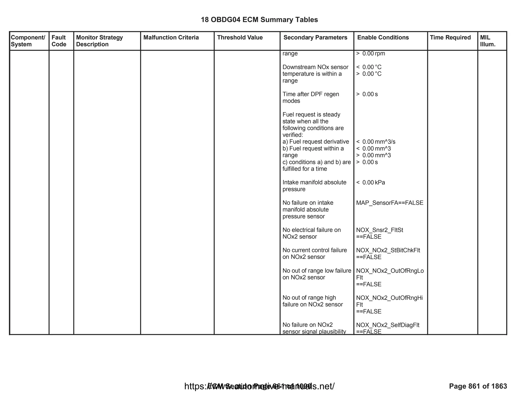
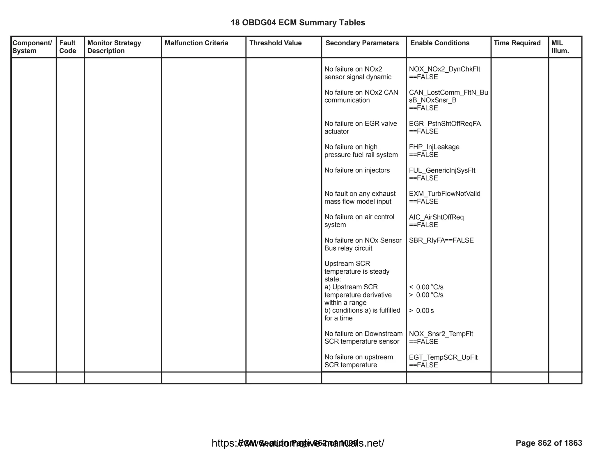
![Component/
System
Fault
Code
Monitor Strategy
Description
Malfunction Criteria Threshold Value Secondary Parameters Enable Conditions Time Required MIL
Illum.
O2 Sensor
Pumping
Current Trim
Circuit Low
Bank 1
Sensor 2
P22B6 This DTC detects if O2
signal is lower than
physical minimum
value.
O2 signal lower than a
minimum value < [%]
0.00
Engine running
System voltage in range
Sensor is fully operative
Enabled in combustion
mode
No pending or confirmed
DTC
> [V]
11.00
OXY_NOx2_O2_RawNot
Rlb
== FALSE
refer to supporting table
(
KaOXYD_b_NOx2SigRn
gEnblCmbMode
)
NOX_Snsr2_NotVld
Time counter: 0
failures out of 0
samples.
Time task 25[ms]
Type B,
2 Trips
18 OBDG04 ECM Summary Tables
ECM Section Page 863 of 1090 Page 863 of 1863
https://www.automotive-manuals.net/](https://image.slidesharecdn.com/gmcenginefaultcodesdtc1-230327071418-56d3c5bb/75/18-OBDG04-ECM-Summary-Tables-863-2048.jpg)
![Component/
System
Fault
Code
Monitor Strategy
Description
Malfunction Criteria Threshold Value Secondary Parameters Enable Conditions Time Required MIL
Illum.
O2 Sensor
Pumping
Current Trim
Circuit High
Bank 1
Sensor 2
P22B7 This DTC detects if O2
signal is higher than
physical maximum
value.
O2 signal higher than a
maximum value > [%]
0.00
Engine running
System voltage in range
Sensor is fully operative
Exhaust gas pressure
No Exhaust Brake active
i.e. intake manifold
pressure
No pending or confirmed
DTCs
> [V]
11.00
OXY_NOx2_O2_RawNot
Rlb
== FALSE
< [kPa]
0.00
< [kPa]
0.00
NOX_Snsr2_NotVld
NOX_Snsr2_PresFlt
(MAP_SensorFA
AND
)
MAP_SensorTFTKO
Time counter: 0
failures out of 0
samples.
Time task 25[ms]
Type B,
2 Trips
18 OBDG04 ECM Summary Tables
ECM Section Page 864 of 1090 Page 864 of 1863
https://www.automotive-manuals.net/](https://image.slidesharecdn.com/gmcenginefaultcodesdtc1-230327071418-56d3c5bb/75/18-OBDG04-ECM-Summary-Tables-864-2048.jpg)
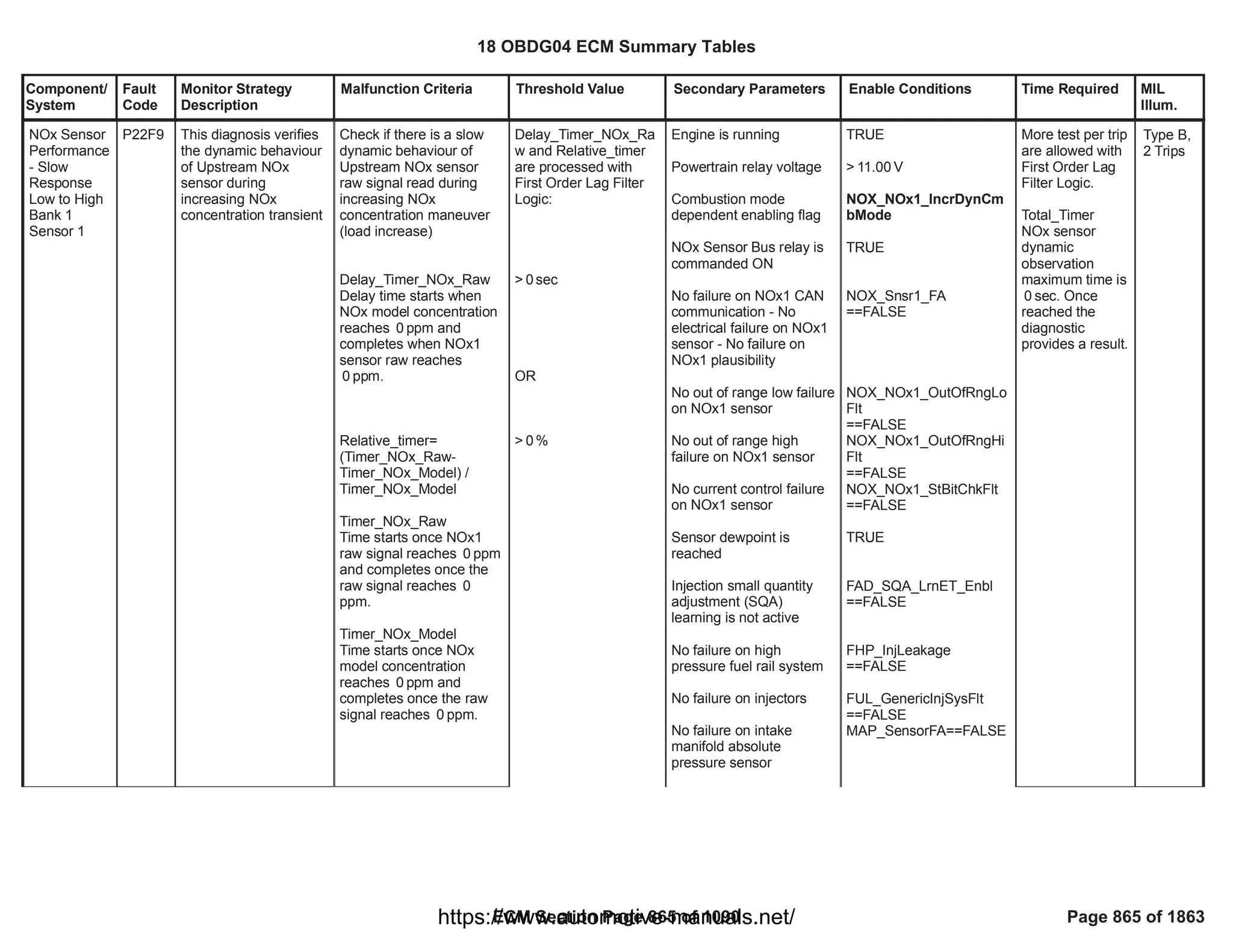
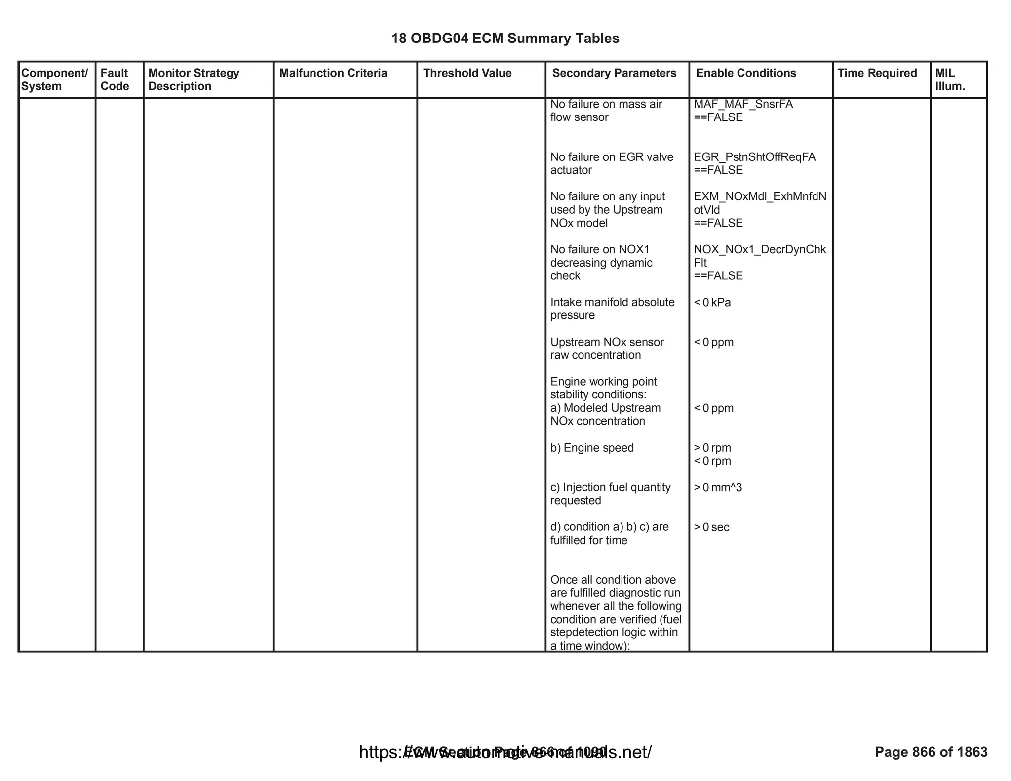

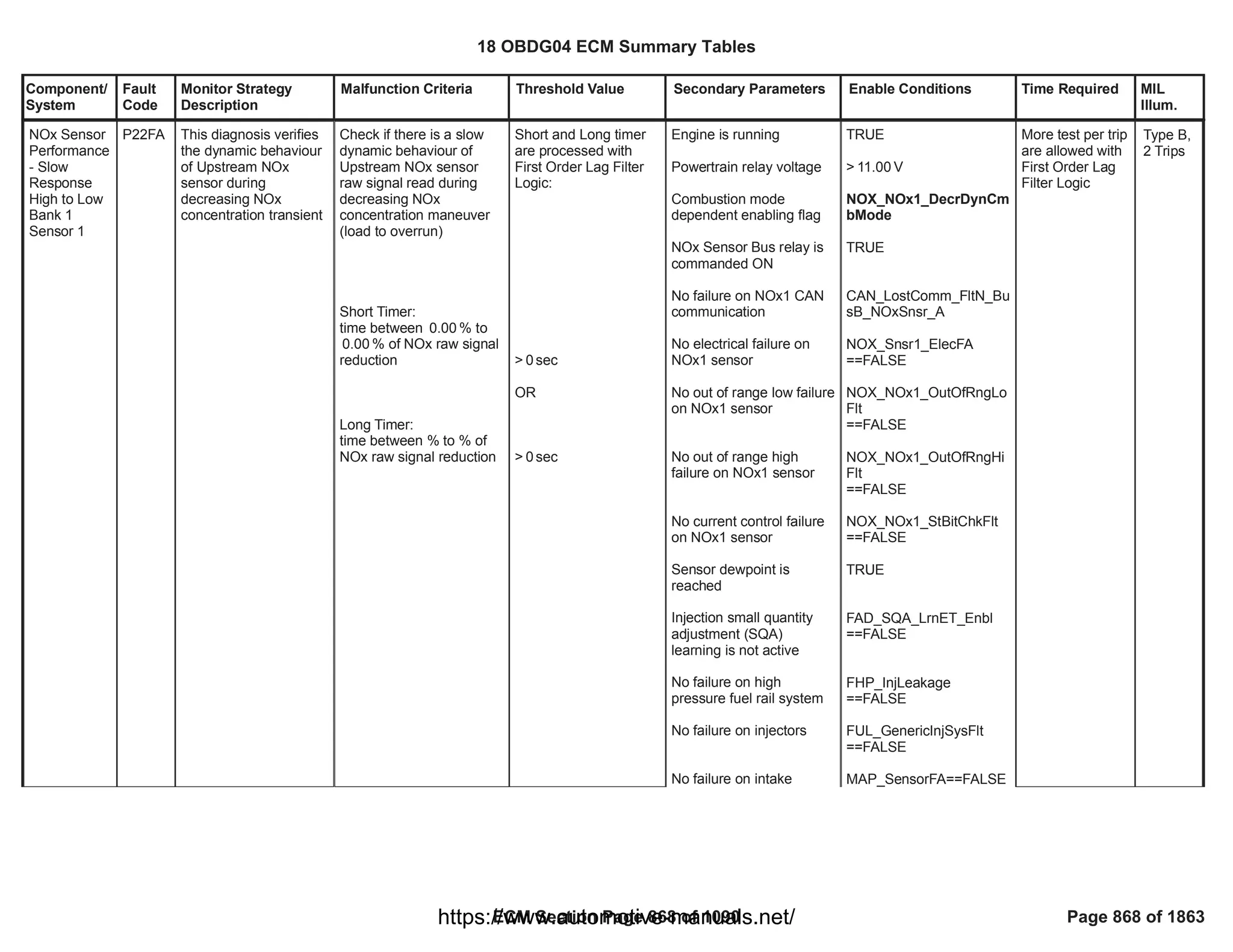
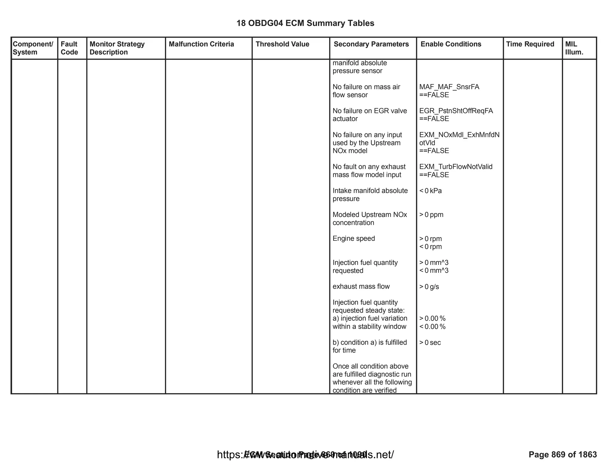
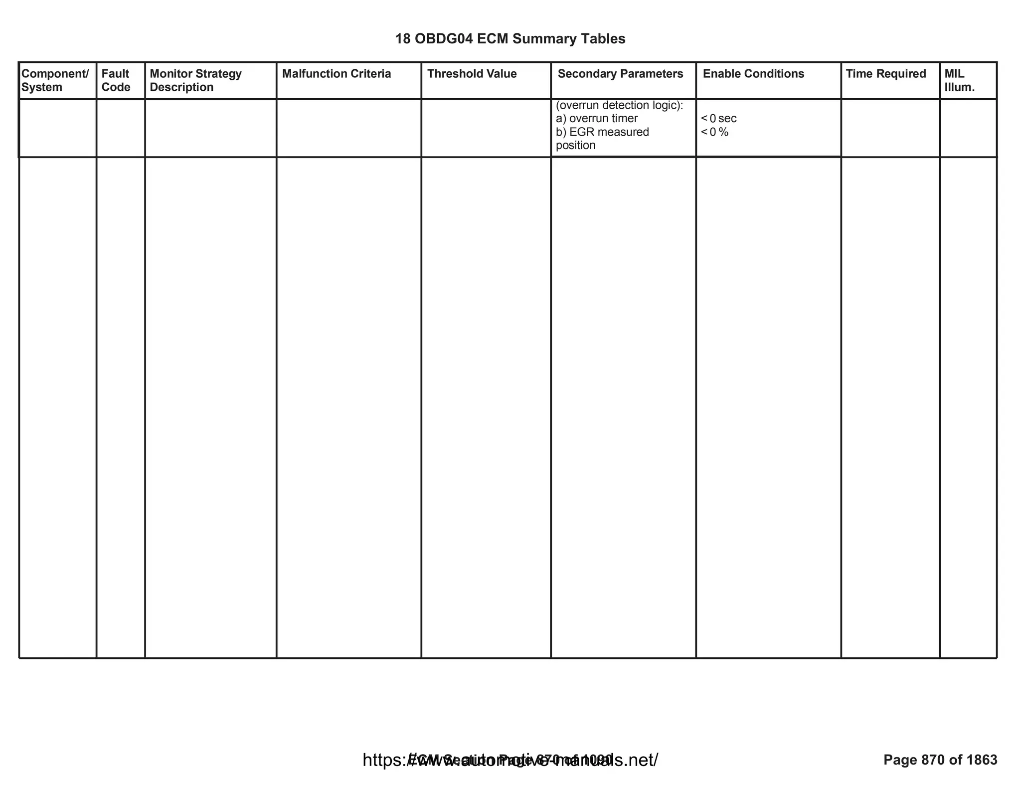
![Component/
System
Fault
Code
Monitor Strategy
Description
Malfunction Criteria Threshold Value Secondary Parameters Enable Conditions Time Required MIL
Illum.
Turbocharge
r VGT A
Stuck
Closed (VGT
Smart)
P2599 This monitor detects
the VGT vanes
mechanically stuck in a
certain position
different from their
defaulted position (fully
open) when the
actuator is no longer
driven (missing
defaulted position)
Measured VGT position >
maximum threshold
> [%]
5.00 P0046 is already set
Waiting time after driver
shut off > minimum
threshold (needed for the
spring to drive the valve in
its defaulted position)
Diagnostic system
enabled (no clear code or
EOT in progress)
VGT position closed loop
control active (no faults
present on
VGT position sensor, VGT
vanes, VGT position
control deviation)
> [s]
0.00
VGT_PstnSnsrOfstFA
==FALSE
VGT_SmartActrFA
==FALSE
==
CFM_VGT_CommFA
FALSE
No debounce is
present: DTC
sets as soon as
the error is
present
Function task:
25 ms
Type A,
1 Trips
18 OBDG04 ECM Summary Tables
ECM Section Page 871 of 1090 Page 871 of 1863
https://www.automotive-manuals.net/](https://image.slidesharecdn.com/gmcenginefaultcodesdtc1-230327071418-56d3c5bb/75/18-OBDG04-ECM-Summary-Tables-871-2048.jpg)
![Component/
System
Fault
Code
Monitor Strategy
Description
Malfunction Criteria Threshold Value Secondary Parameters Enable Conditions Time Required MIL
Illum.
O2S Circuit
Range/
Performance
Bank 1
Sensor 2
P2A01 This DTC aims to
detect a drift of Sensor
2 O2 measured value
(A) from Sensor 1 O2
measured value (B)
when the latter can be
considered stable
during full load
condition.
EWMA filtered error (A -
B) in full load condition is
out of plausible range
> [%]
0.00
< [%]
0.00
Engine running
System voltage in range
Sensor is fully operative
Sensor 1 is fully operative
No pending or confirmed
DTCs
DTC P2A00 is running
Air mass flown since
P2A00 is enabled
> [V]
11.00
OXY_O2_NOx2_PresCm
pNotRlb
== FALSE
OXY_O2_NOx1_PresCm
pNotRlb
== FALSE
NOX_Snsr2_NotVld
NOX_Snsr2_PresFlt
OXY_NOx2SignRngChkFl
t
OXY_NOx1_O2_Flt
(MAF_SensorFA
AND
)
MAF_SensorTFTKO
(see P2A00 Fault code)
> [g]
0.00
EWMA filtering:
multiple tests per
trip are allowed.
Type B,
2 Trips
18 OBDG04 ECM Summary Tables
ECM Section Page 872 of 1090 Page 872 of 1863
https://www.automotive-manuals.net/](https://image.slidesharecdn.com/gmcenginefaultcodesdtc1-230327071418-56d3c5bb/75/18-OBDG04-ECM-Summary-Tables-872-2048.jpg)
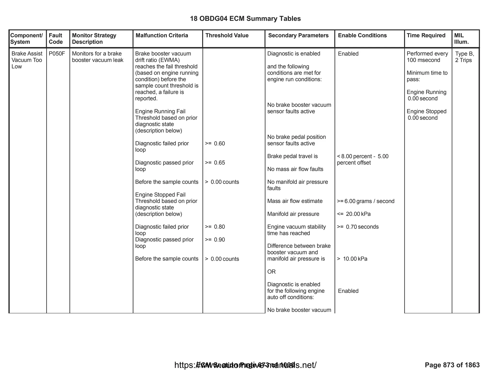
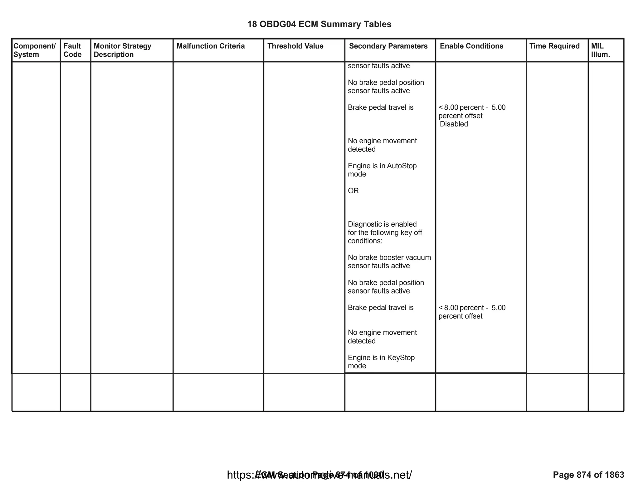
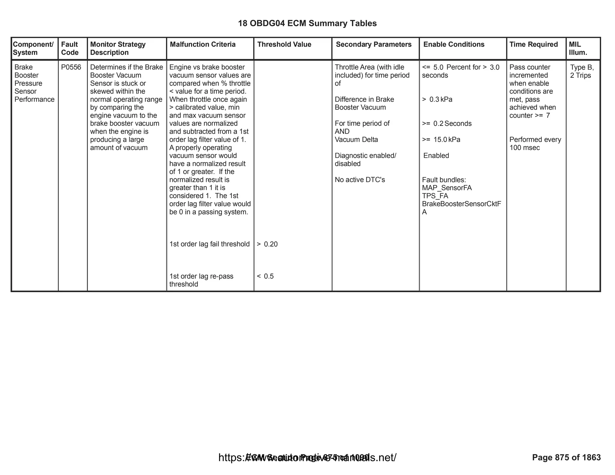

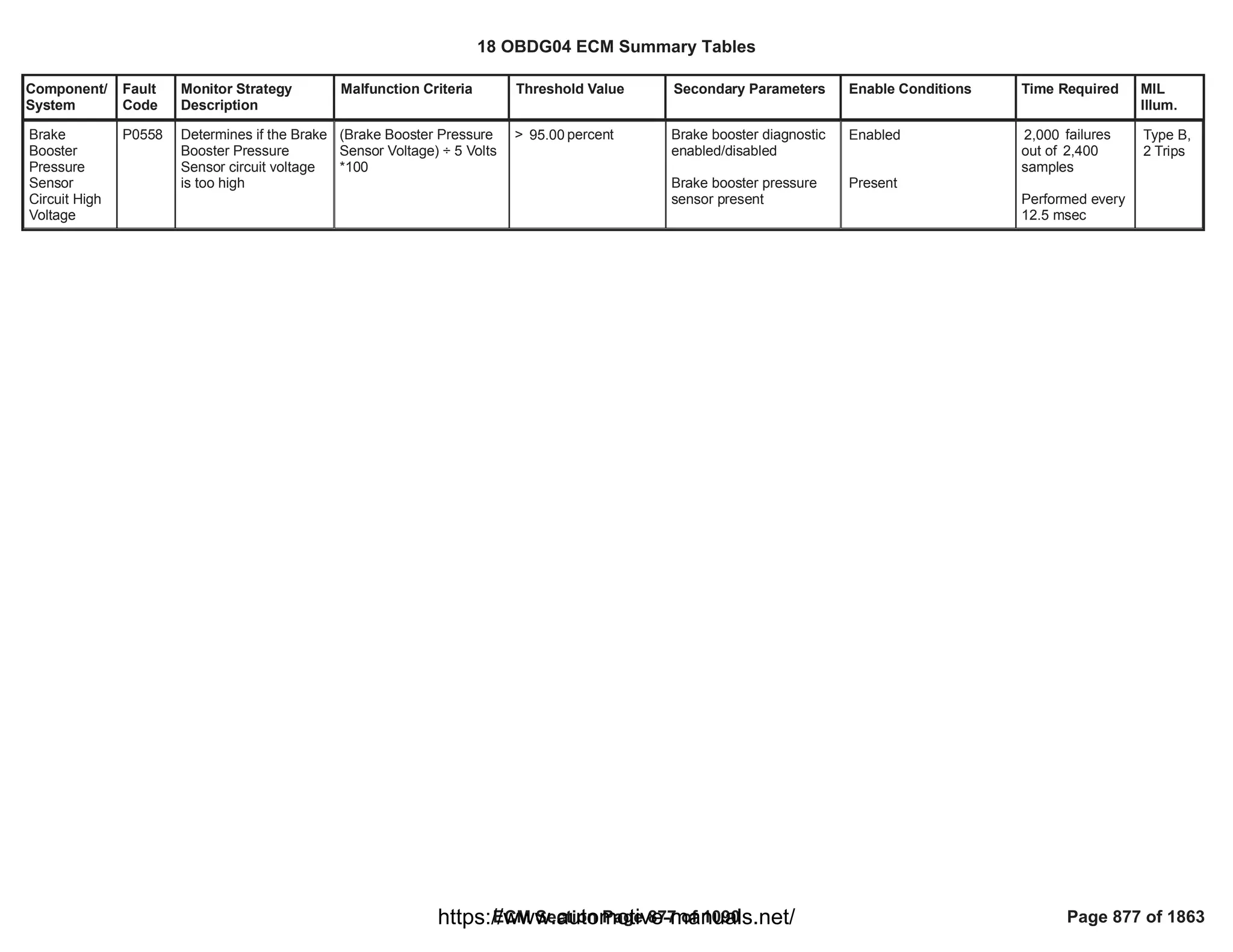

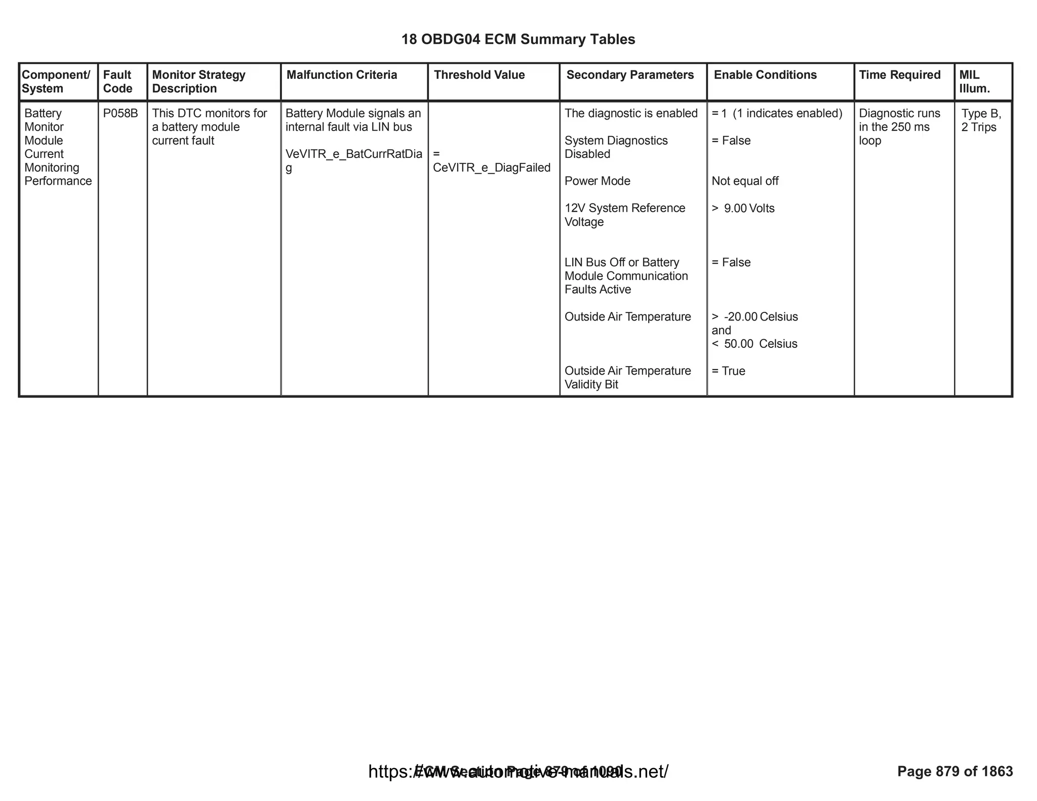
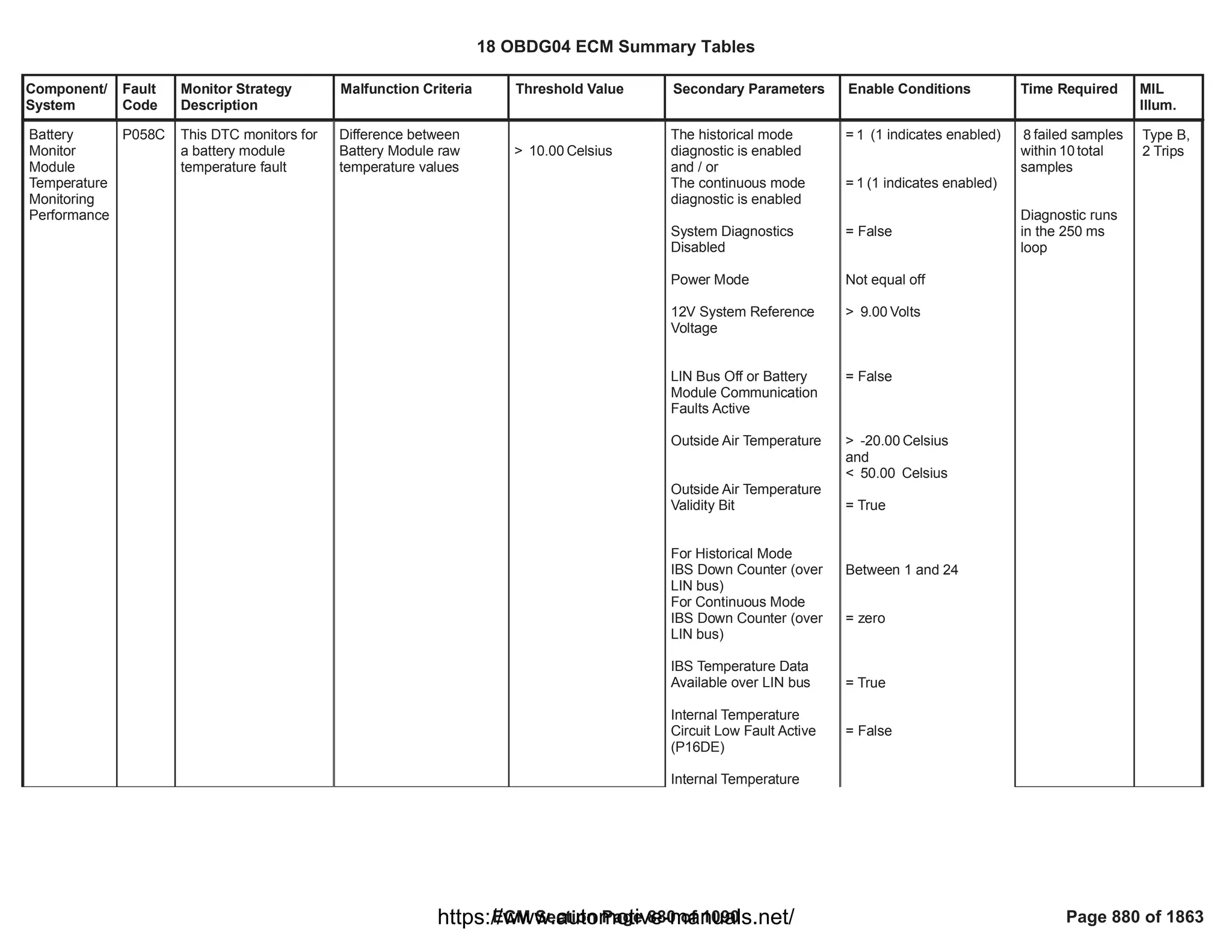
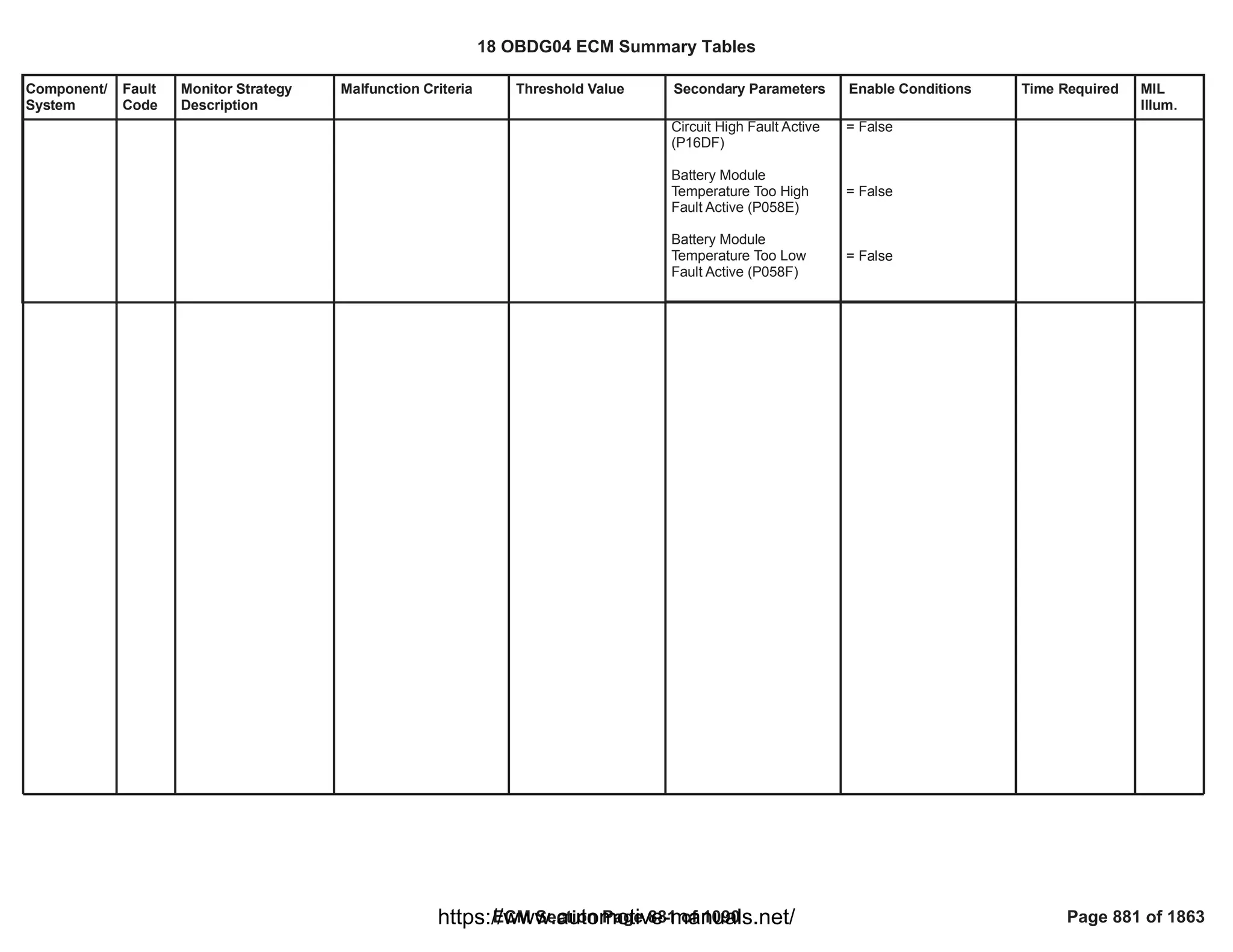
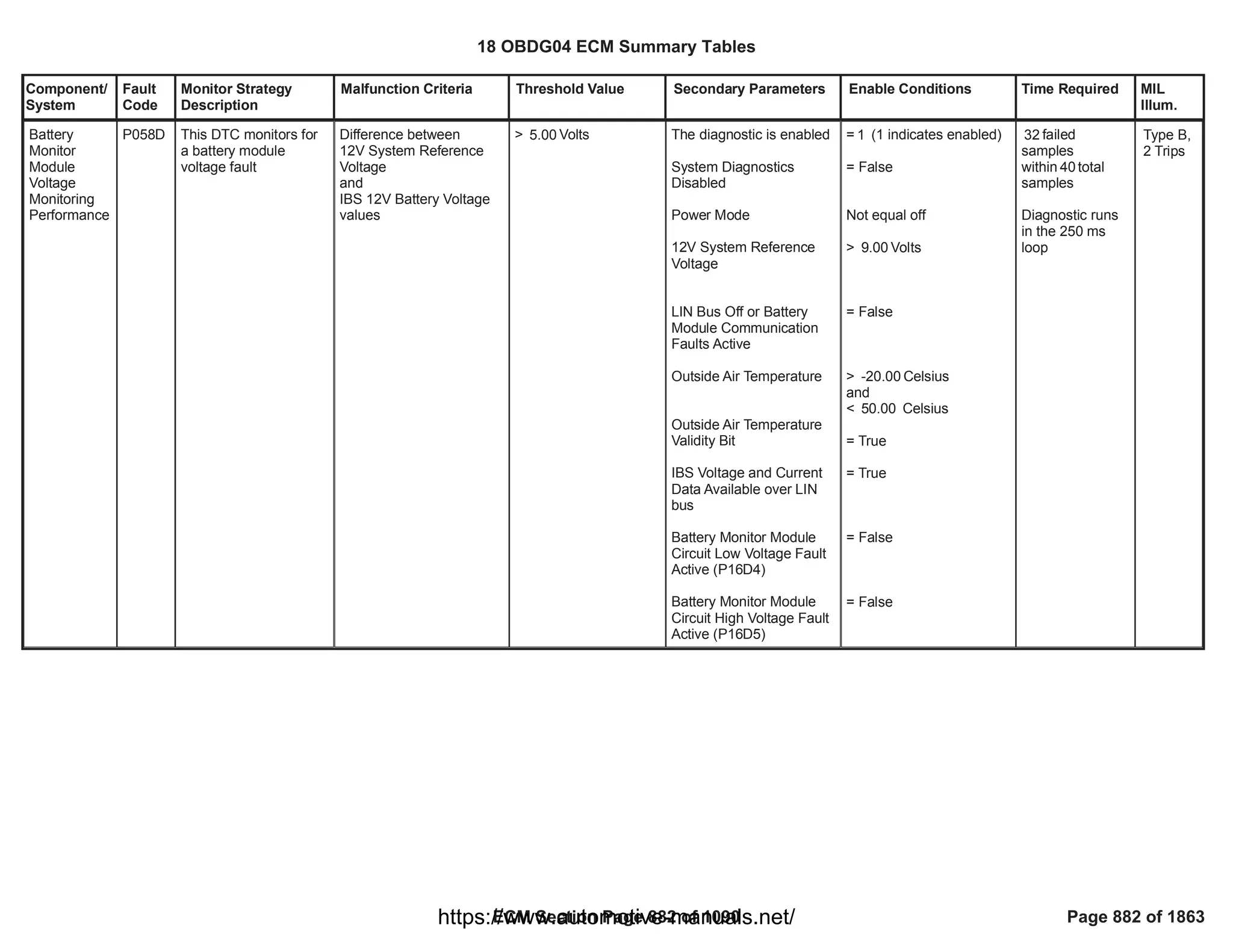
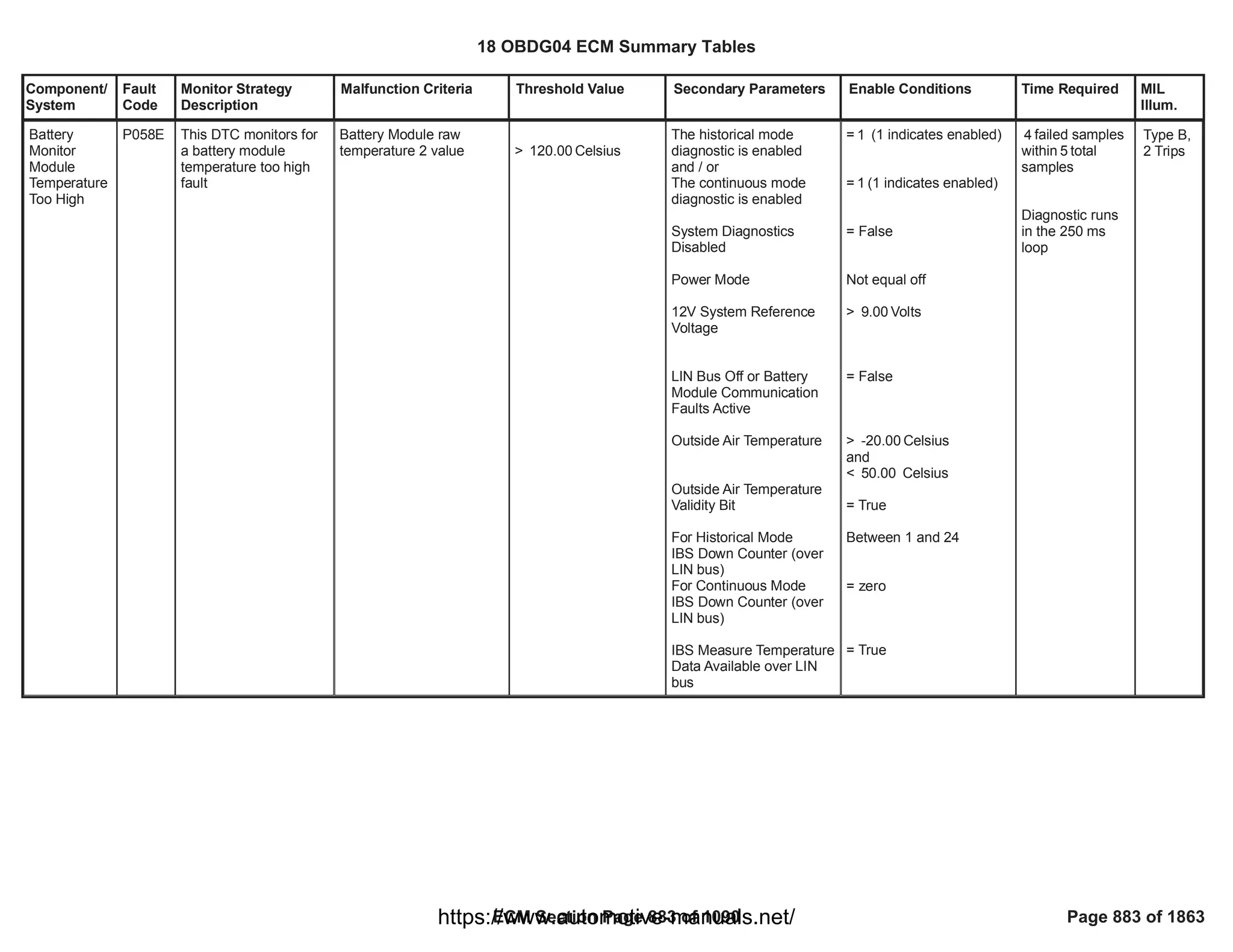


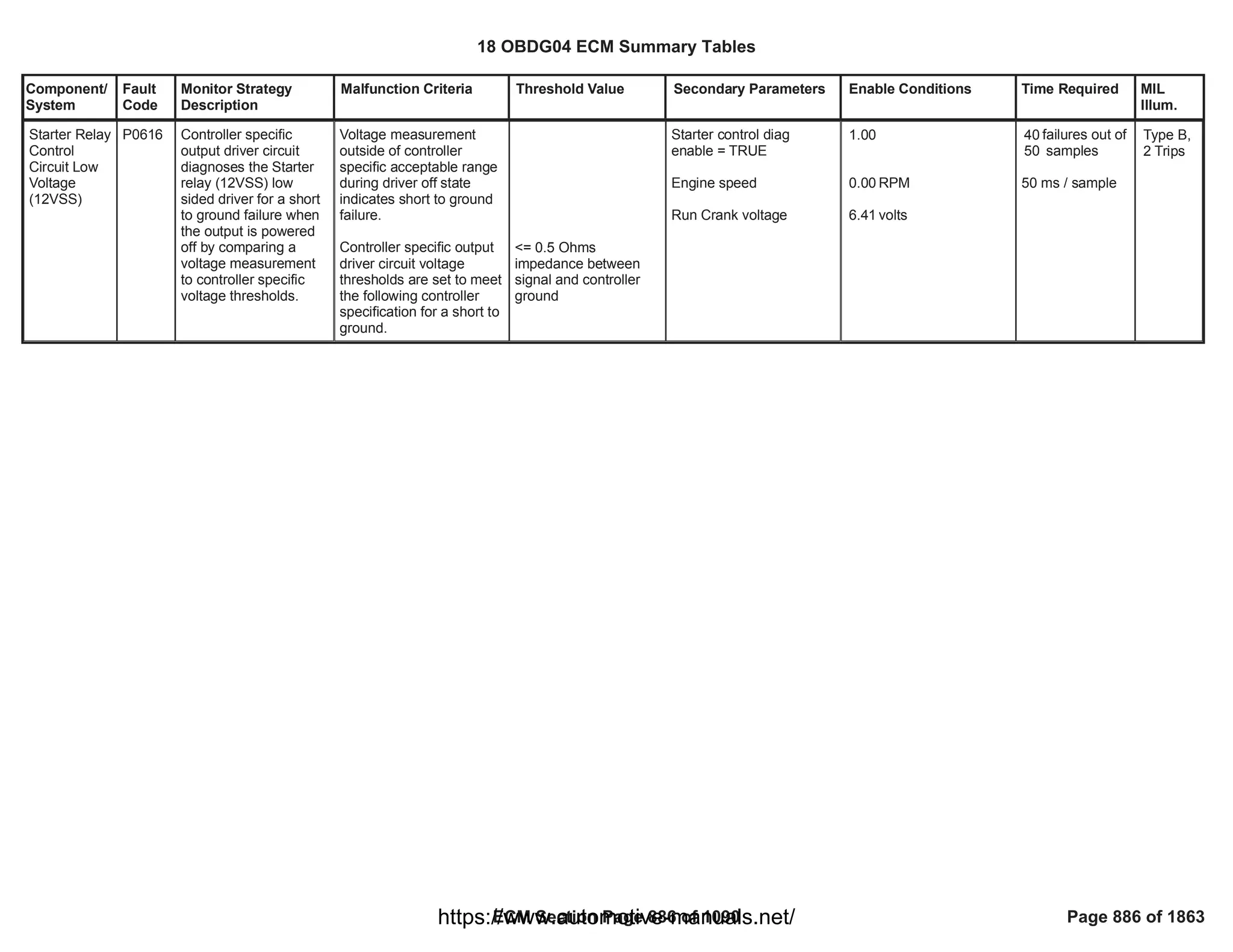
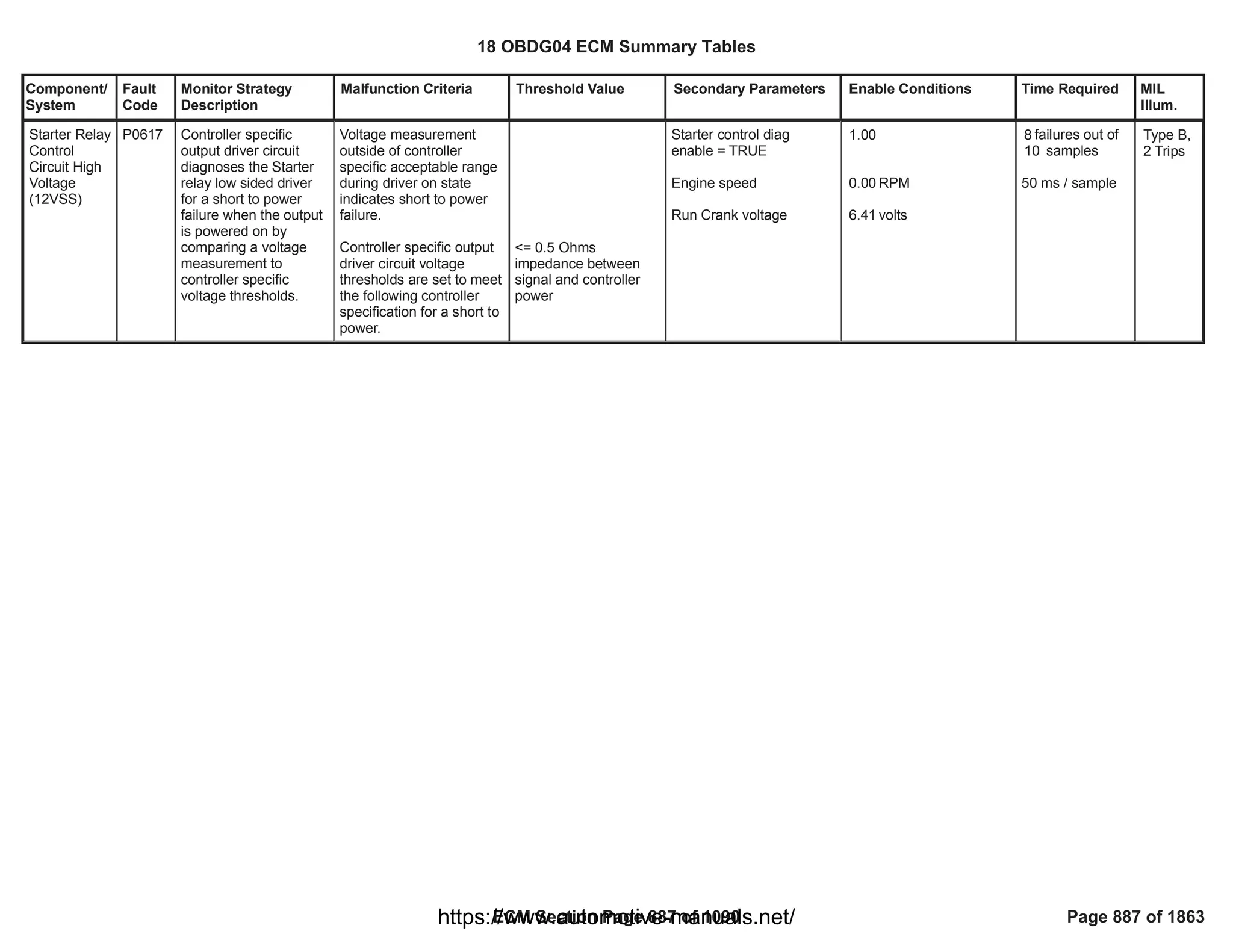
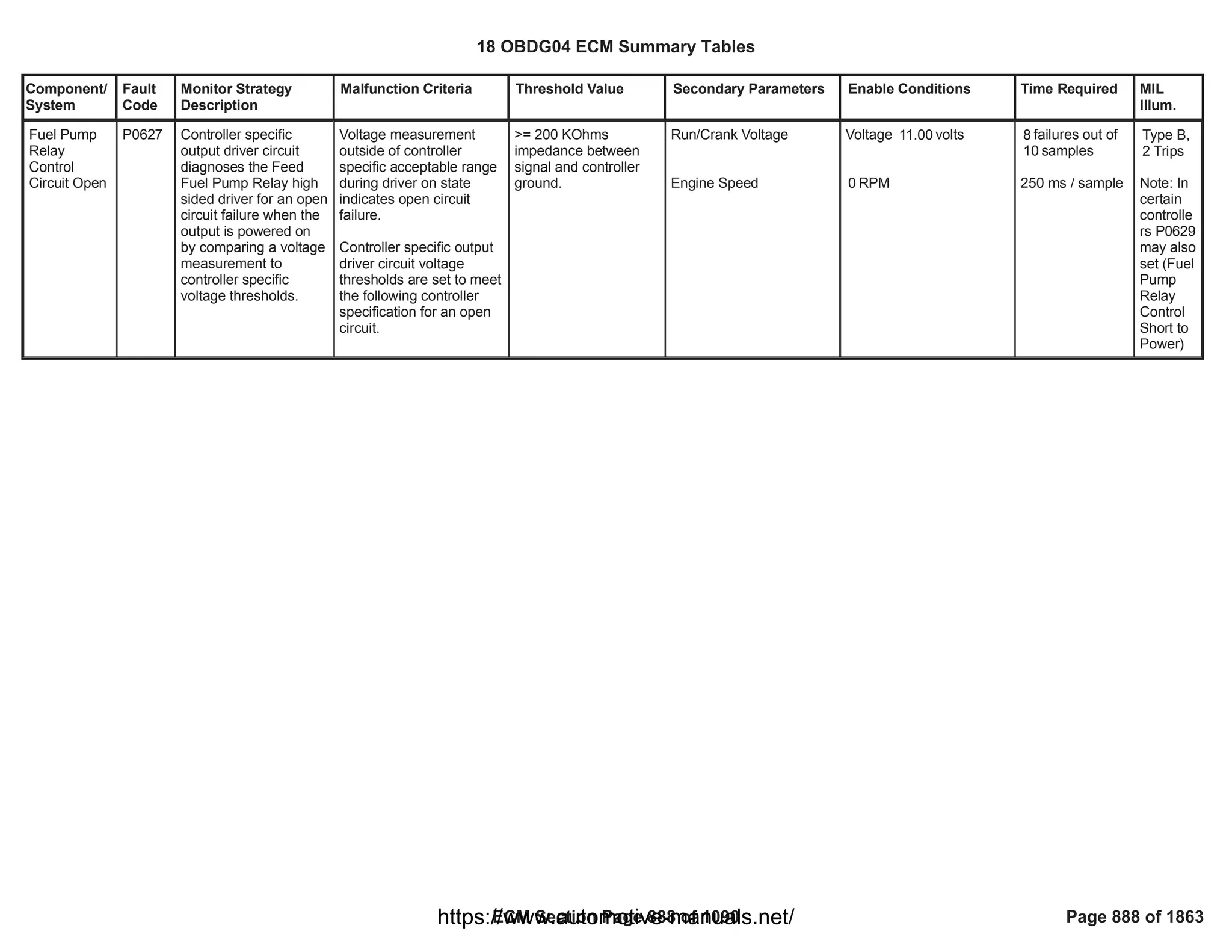
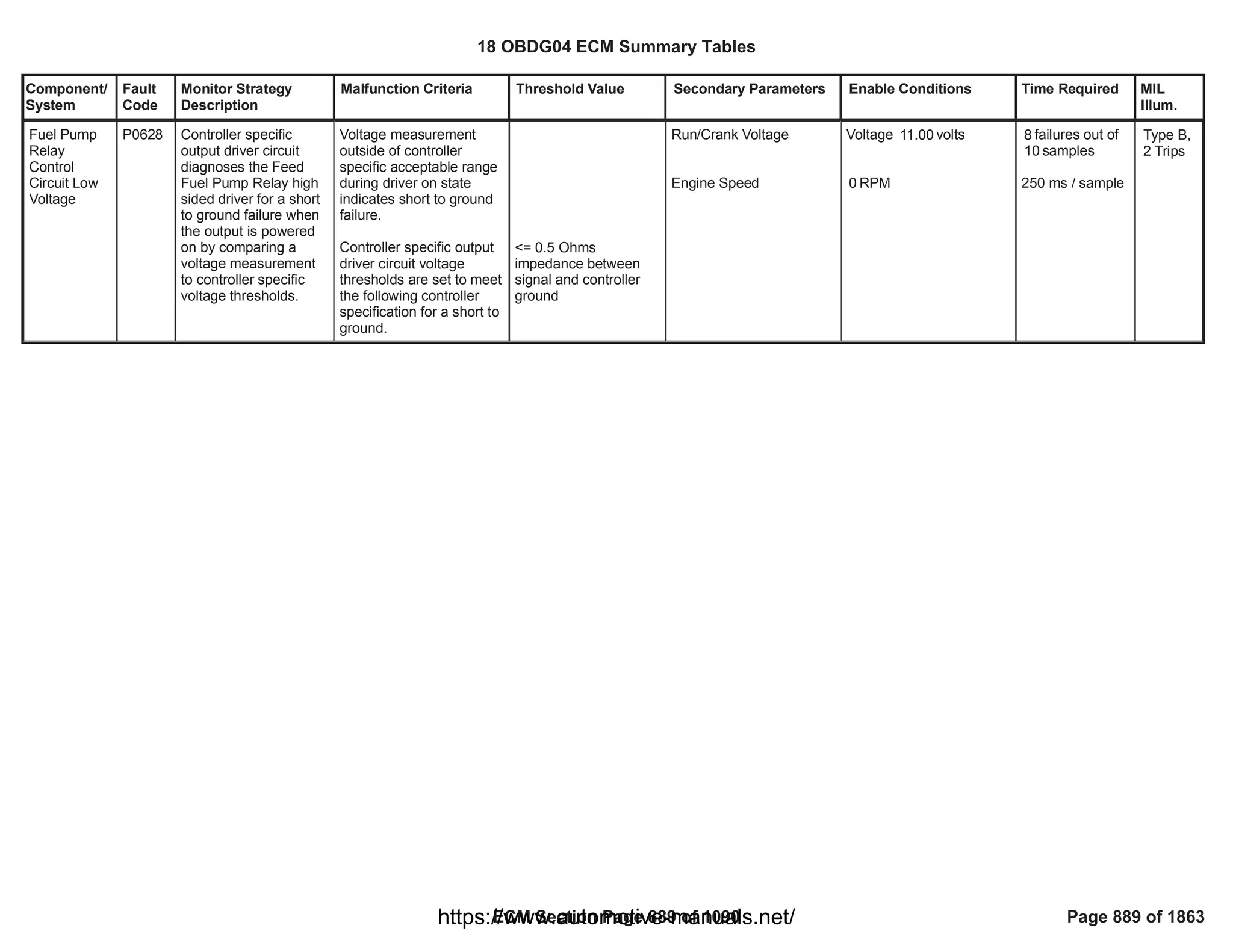
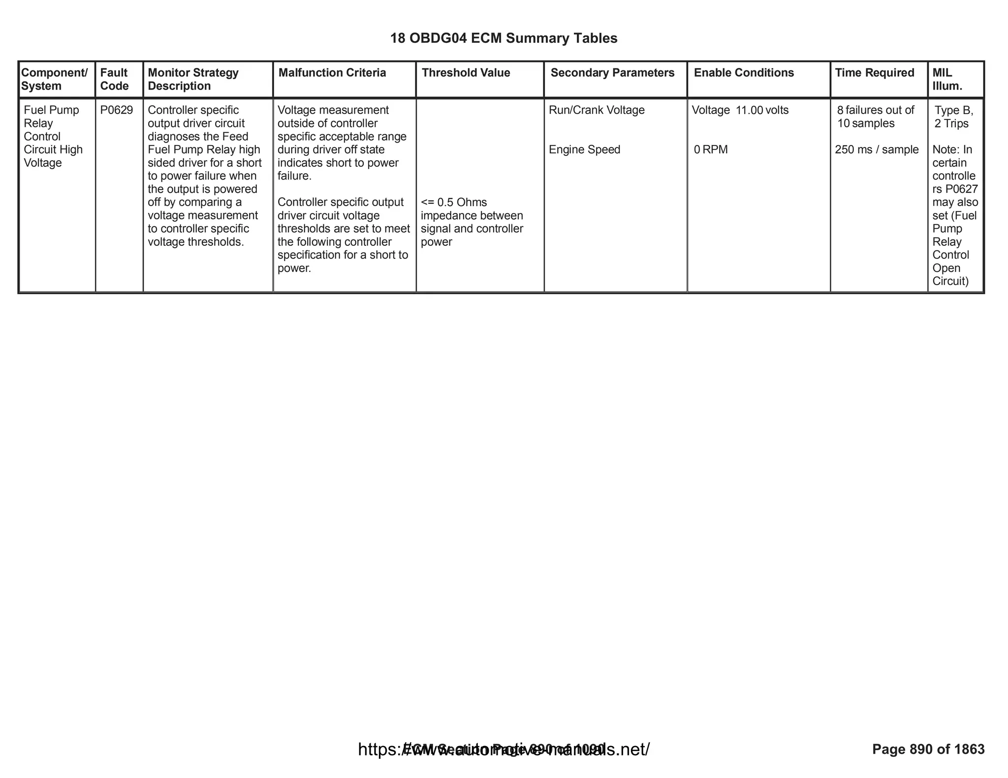
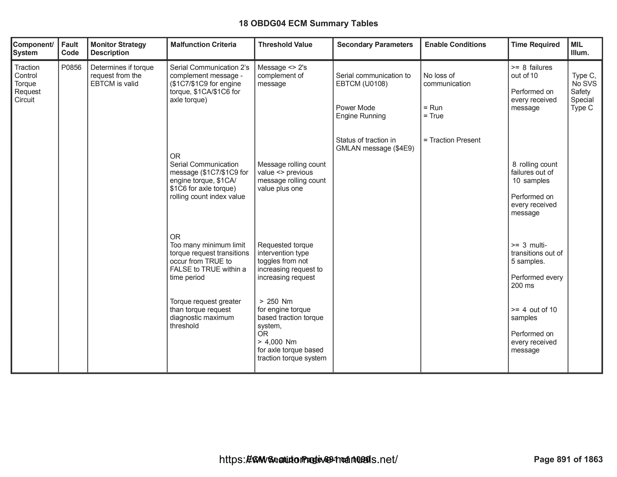

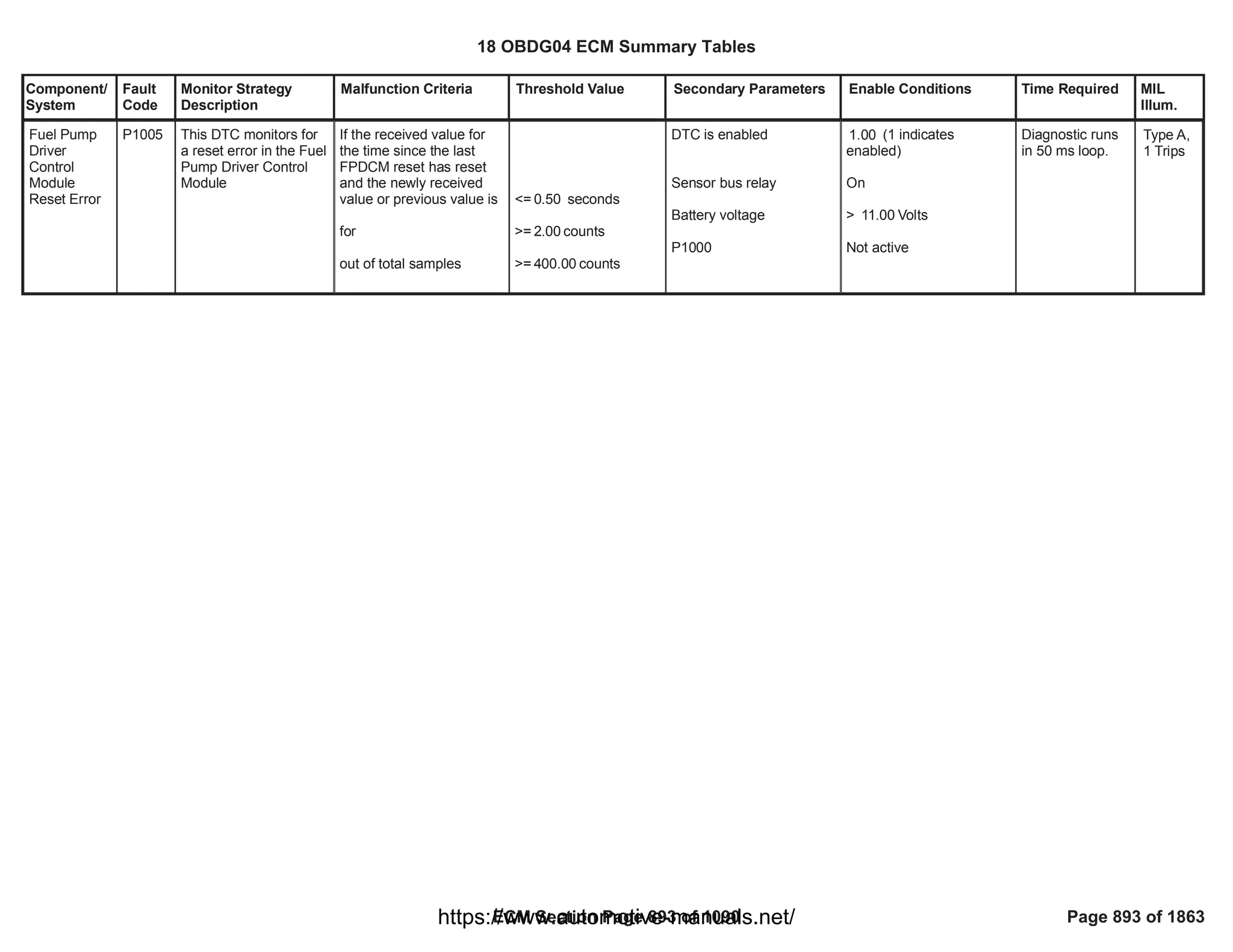
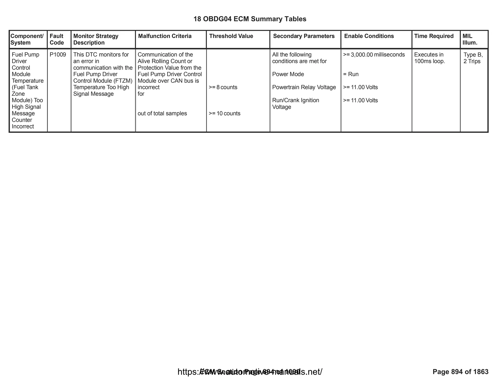


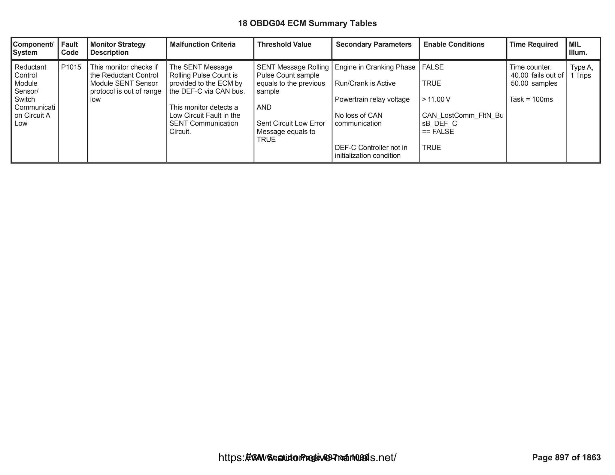
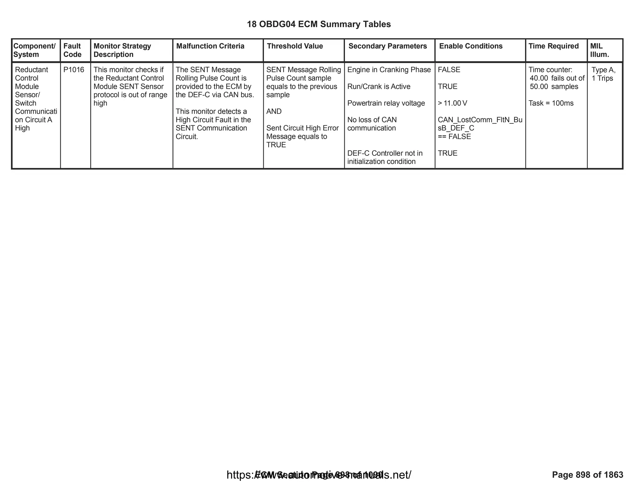
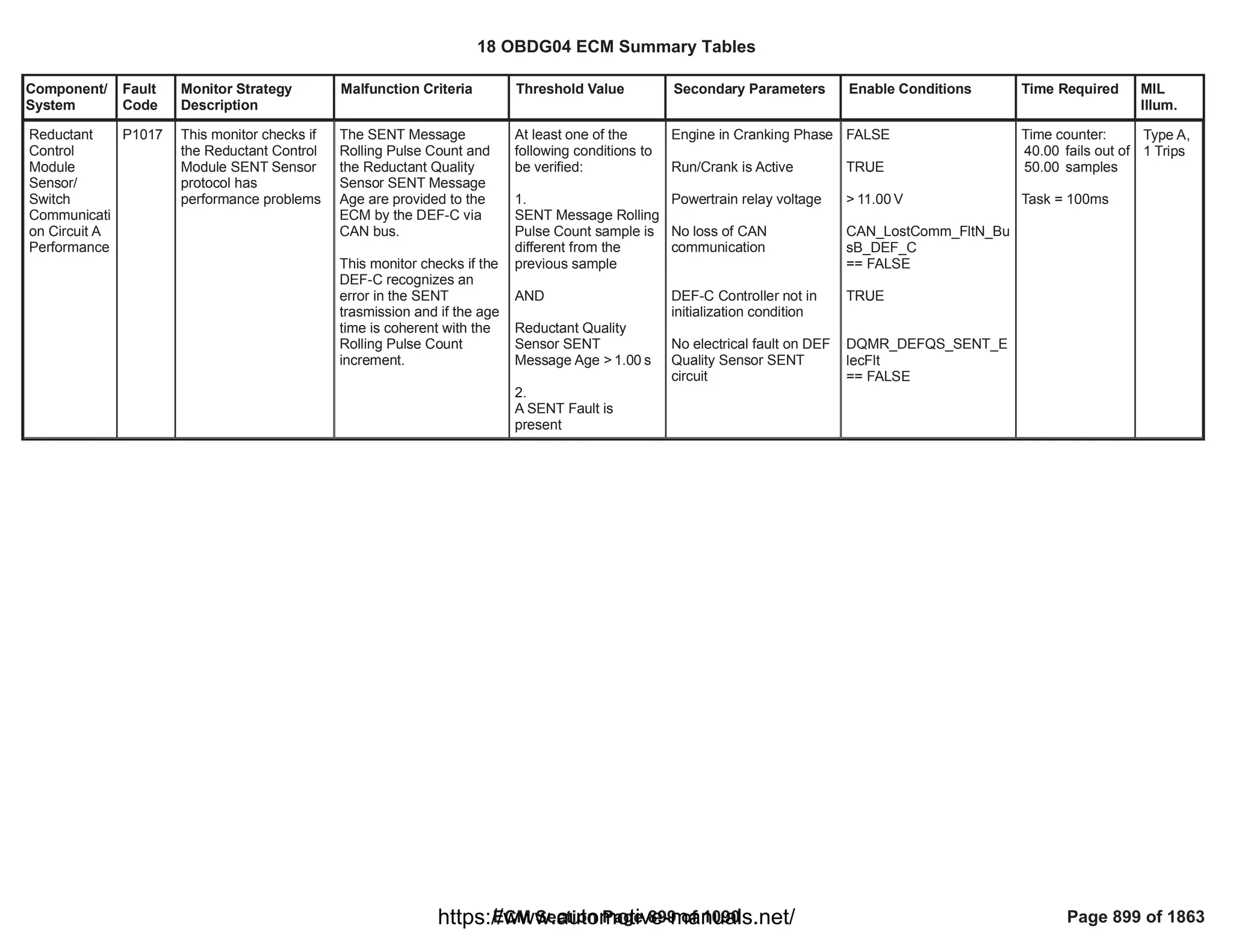
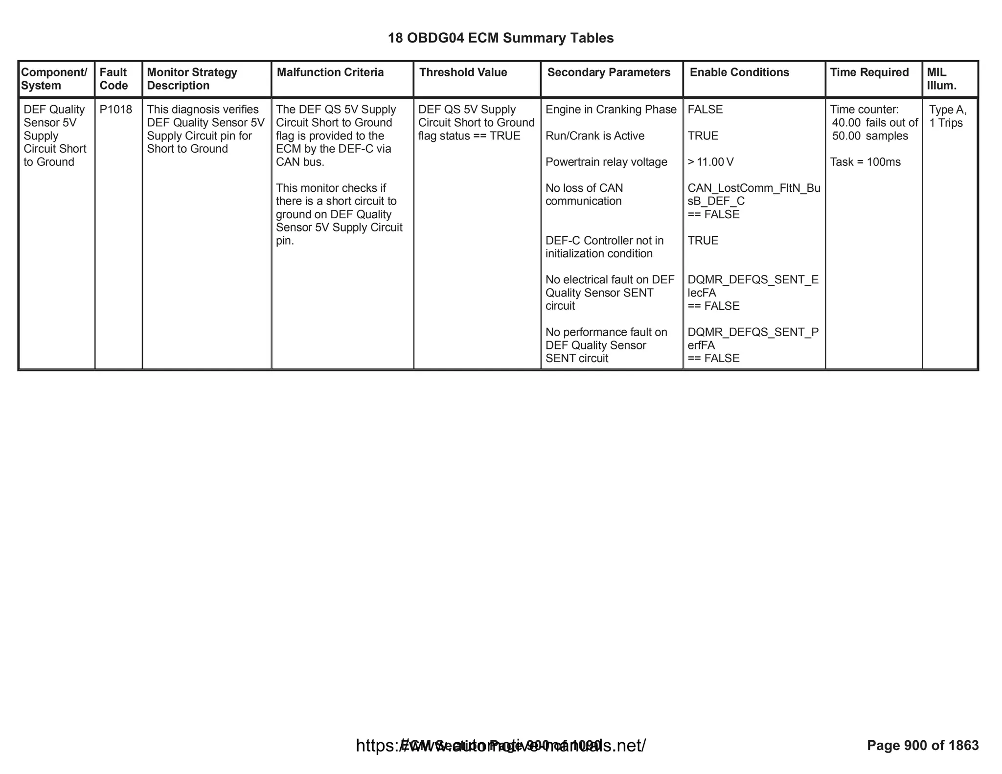

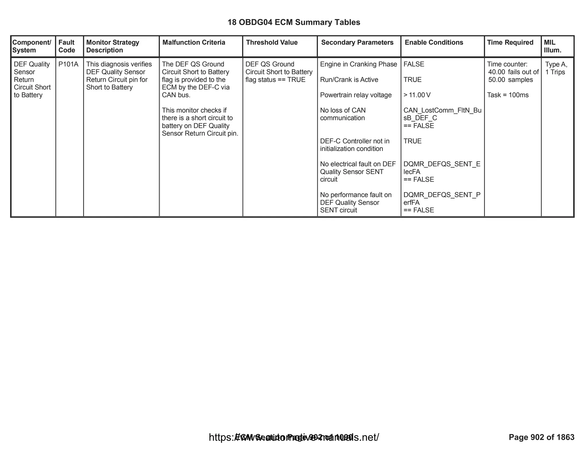
![Component/
System
Fault
Code
Monitor Strategy
Description
Malfunction Criteria Threshold Value Secondary Parameters Enable Conditions Time Required MIL
Illum.
Reductant
Pump Driver
High
Temperature
P103F This diagnosis verifies
that the Motor Mosfet
Driver Temperature is
too High
Motor Mosfet Driver
Temperature too High
Error status == FAULT
VeSCRR_e_PmpDrvrH
iTemp == FAULT
Test enabled by
calibration
Key on (OR engine
running)
Engine is not cranking
Battery voltage
No loss of CAN
communication
Motor Mosfet Driver
Temperature too High
Error status provided by
DEF control module
different from
INDETERMINATE
[Boolean]
1.00
> [V]
11.00
U010E, Lost
Communication With
Reductant Control Module
40.00
failures
out of
50.00
samples
Time basis =
100ms/sample
Type A,
1 Trips
18 OBDG04 ECM Summary Tables
ECM Section Page 903 of 1090 Page 903 of 1863
https://www.automotive-manuals.net/](https://image.slidesharecdn.com/gmcenginefaultcodesdtc1-230327071418-56d3c5bb/75/18-OBDG04-ECM-Summary-Tables-903-2048.jpg)
![Component/
System
Fault
Code
Monitor Strategy
Description
Malfunction Criteria Threshold Value Secondary Parameters Enable Conditions Time Required MIL
Illum.
Reductant
Pump A
Control
Circuit
Shorted
P1040 This diagnosis verifies
that the DEF pump
phases are shorted
Motor Pump Phases
Shorted Error status
provided by DEF control
module == FAULT
VeSCRR_e_PmpMtrS
horted==FAULT
Test enabled by
calibration
Key on (OR engine
running)
Engine is not cranking
Battery voltage
No loss of CAN
comunication
Motor Pump Phases
Shorted Error status
provided by DEF control
module different from
indeterminate
1.00
> [V]
11.00
U010E, Lost
Communication With
Reductant Control Module
(SCR)
20.00
failures
out of
samples
25.00
Time basis =
100ms/sample
Type A,
1 Trips
18 OBDG04 ECM Summary Tables
ECM Section Page 904 of 1090 Page 904 of 1863
https://www.automotive-manuals.net/](https://image.slidesharecdn.com/gmcenginefaultcodesdtc1-230327071418-56d3c5bb/75/18-OBDG04-ECM-Summary-Tables-904-2048.jpg)
![Component/
System
Fault
Code
Monitor Strategy
Description
Malfunction Criteria Threshold Value Secondary Parameters Enable Conditions Time Required MIL
Illum.
Reductant
Injection
Valve Supply
Voltage
Circuit Low
Bank 1 Unit
1
P1048 This diagnosis verifies
if a DEF dosing valve
high side short to
ground occurred
HWIO interface
DEFMV_ENABLE_GROU
ND_SHORT = Fault
VeHWIO_e_DEFMV_E
nbl_Gsht ==
CeSCRR_e_Fault
Test enabled by
calibration
Key on (OR engine
running)
Engine is not cranking
Battery voltage
HWIO interface
DEFMV_ENABLE_GROU
ND_SHORT different from
INDETERMINATE
1.00
> [V]
11.00
30.00
failures
out of
60.00
samples
Time basis =
100ms/sample
Type A,
1 Trips
18 OBDG04 ECM Summary Tables
ECM Section Page 905 of 1090 Page 905 of 1863
https://www.automotive-manuals.net/](https://image.slidesharecdn.com/gmcenginefaultcodesdtc1-230327071418-56d3c5bb/75/18-OBDG04-ECM-Summary-Tables-905-2048.jpg)
![Component/
System
Fault
Code
Monitor Strategy
Description
Malfunction Criteria Threshold Value Secondary Parameters Enable Conditions Time Required MIL
Illum.
Reductant
Injection
Valve Supply
Voltage
Circuit High
Bank 1 Unit
1
P1049 This diagnosis verifies
if a DEF dosing valve
high side short to
power occurred
HWIO interface
DEFMV_ENABLE_POWE
R_SHORT = Fault
VeHWIO_e_DEFMV_E
nbl_Psht ==
CeSCRR_e_Fault
Test enabled by
calibration
Key on (OR engine
running)
Engine is not cranking
Battery voltage
HWIO interface
DEFMV_ENABLE_POWE
R_SHORT different from
INDETERMINATE
1.00
> [V]
11.00
30.00
failures out of
60.00
samples
Time basis =
100ms/sample
Type A,
1 Trips
18 OBDG04 ECM Summary Tables
ECM Section Page 906 of 1090 Page 906 of 1863
https://www.automotive-manuals.net/](https://image.slidesharecdn.com/gmcenginefaultcodesdtc1-230327071418-56d3c5bb/75/18-OBDG04-ECM-Summary-Tables-906-2048.jpg)
![Component/
System
Fault
Code
Monitor Strategy
Description
Malfunction Criteria Threshold Value Secondary Parameters Enable Conditions Time Required MIL
Illum.
Reductant
Level
Sensor-
Invalid
Range
P1050 This diagnosis verifies
that the DEF level
sensor raw signal is not
within plausible range
DEF level sensor raw
value is not within
calibrated range (for
discrete level sensor,
each discrete level has its
plausible range)
Supply voltage
parcentage is outside of
the following ranges:
( ; ) [%]
2.00 5.50
( ; ) [%]
17.30 22.00
( ; ) [%]
32.90 38.80
( ; ) [%]
63.10 69.40
Test enabled by
calibration
Key on (OR engine
running)
Engine is not cranking
Battery voltage
No loss of CAN
communication
No electrical faults on
DEF level sensor
Discrete Level sensor
used
1.00
> [V]
11.00
U010E, Lost
Communication With
Reductant Control Module
(SCR)
SCR_DEFLS_ElecFltSt
== FALSE
CeSCRI_e_DEF_LvlSnsr
Discrete ==
CeSCRI_e_DEF_LvlSnsr
Discrete
40.00
failures out of
50.00
samples
Time basis =
100ms/sample
Type B,
2 Trips
18 OBDG04 ECM Summary Tables
ECM Section Page 907 of 1090 Page 907 of 1863
https://www.automotive-manuals.net/](https://image.slidesharecdn.com/gmcenginefaultcodesdtc1-230327071418-56d3c5bb/75/18-OBDG04-ECM-Summary-Tables-907-2048.jpg)
![Component/
System
Fault
Code
Monitor Strategy
Description
Malfunction Criteria Threshold Value Secondary Parameters Enable Conditions Time Required MIL
Illum.
Reductant
Heater 1
Driver Over
Temperature
Fault
P1051 This diagnosis verifies
if the driver of the DEF
tank heater is affected
by overtemperature
Tank Heater driver over
temperature flag reports a
fail
VeSCRR_e_HeatA_Ov
erTemp ==
CeSCRR_e_fault
Test enabled by
calibration
Temperature used by the
heating strategy to switch
on the heaters
Battery voltage
Key on (OR engine
running)
Engine is not cranking
No loss of CAN
communication
DEF Temperature sensor
not in fault
Tank Heater driver over
temperature flag different
from INDETERMINATE
1.00
< [°C]
60.00
> [V]
11.00
U010E, Lost
Communication With
Reductant Control Module
(SCR)
(GetCANR_b_LostComm
_FltN= FALSE)
SCR_DEFTS_FA
== FALSE
8.00
failures out of
10.00
samples
Time basis =
500ms/sample
Type A,
1 Trips
18 OBDG04 ECM Summary Tables
ECM Section Page 908 of 1090 Page 908 of 1863
https://www.automotive-manuals.net/](https://image.slidesharecdn.com/gmcenginefaultcodesdtc1-230327071418-56d3c5bb/75/18-OBDG04-ECM-Summary-Tables-908-2048.jpg)
![Component/
System
Fault
Code
Monitor Strategy
Description
Malfunction Criteria Threshold Value Secondary Parameters Enable Conditions Time Required MIL
Illum.
Reductant
Heater 2
Driver Over
Temperature
Fault
P1052 This diagnosis verifies
if the driver of the DEF
dosing line heater is
affected by
overtemperature
Line Heater driver over
temperature flag reports a
fail
VeSCRR_e_HeatB_Ov
erTemp ==
CeSCRR_e_fault
Test enabled by
calibration
Temperature used by the
heating strategy to switch
on the heaters
Battery voltage
Key on (OR engine
running)
Engine is not cranking
No loss of CAN
communication
Line Heater driver over
temperature flag different
from INDETERMINATE
== TRUE
1.00
< 60.00
> [V]
11.00
U010E, Lost
Communication With
Reductant Control Module
(SCR)
8.00
failures out of
10.00
samples
Time basis =
500ms/sample
Type A,
1 Trips
18 OBDG04 ECM Summary Tables
ECM Section Page 909 of 1090 Page 909 of 1863
https://www.automotive-manuals.net/](https://image.slidesharecdn.com/gmcenginefaultcodesdtc1-230327071418-56d3c5bb/75/18-OBDG04-ECM-Summary-Tables-909-2048.jpg)
![Component/
System
Fault
Code
Monitor Strategy
Description
Malfunction Criteria Threshold Value Secondary Parameters Enable Conditions Time Required MIL
Illum.
Reductant
Pump A
Speed Low
P105A This diagnosis verifies
that the DEF pump
rotor is stalled
DEF pump commanded to
move forward or reverse
AND
DEF Pump Motor speed
within calibrated range
VeSCRR_n_PmpMtrS
pd > -650.00
AND
VeSCRR_n_PmpMtrS
pd < 650.00
Test enabled by
calibration
Engine is not cranking
Battery voltage
Key on (OR engine
running)
PWM_pump_command
not in fault
DEF motor pump not in
fault
No loss of CAN
communication
Tank Defrost phase
completed
DEF pump commanded to
move forward or reverse
1.00
> [V]
11.00
SCR_DEF_PumpCmdFA
== FALSE
==
SCR_DEFPM_FA
FALSE
U010E, Lost
Communication With
Reductant Control Module
(SCR)
pct duty cycle inside:
( ; ) [%]
39.00 81.00
or
( ; )[%]
11.00 31.00
160.00
failures out of
200.00
samples
Time basis =
25ms
Type A,
1 Trips
18 OBDG04 ECM Summary Tables
ECM Section Page 910 of 1090 Page 910 of 1863
https://www.automotive-manuals.net/](https://image.slidesharecdn.com/gmcenginefaultcodesdtc1-230327071418-56d3c5bb/75/18-OBDG04-ECM-Summary-Tables-910-2048.jpg)
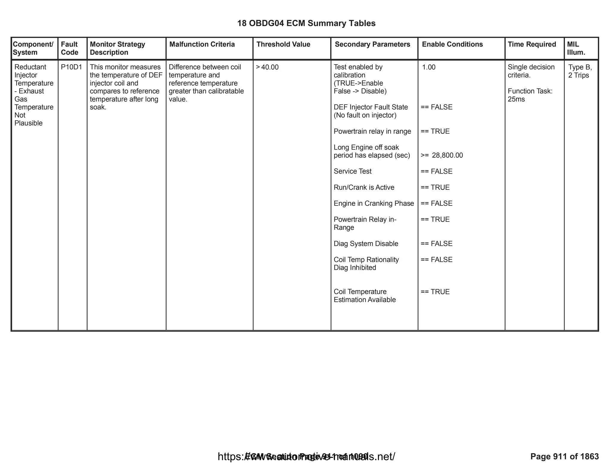

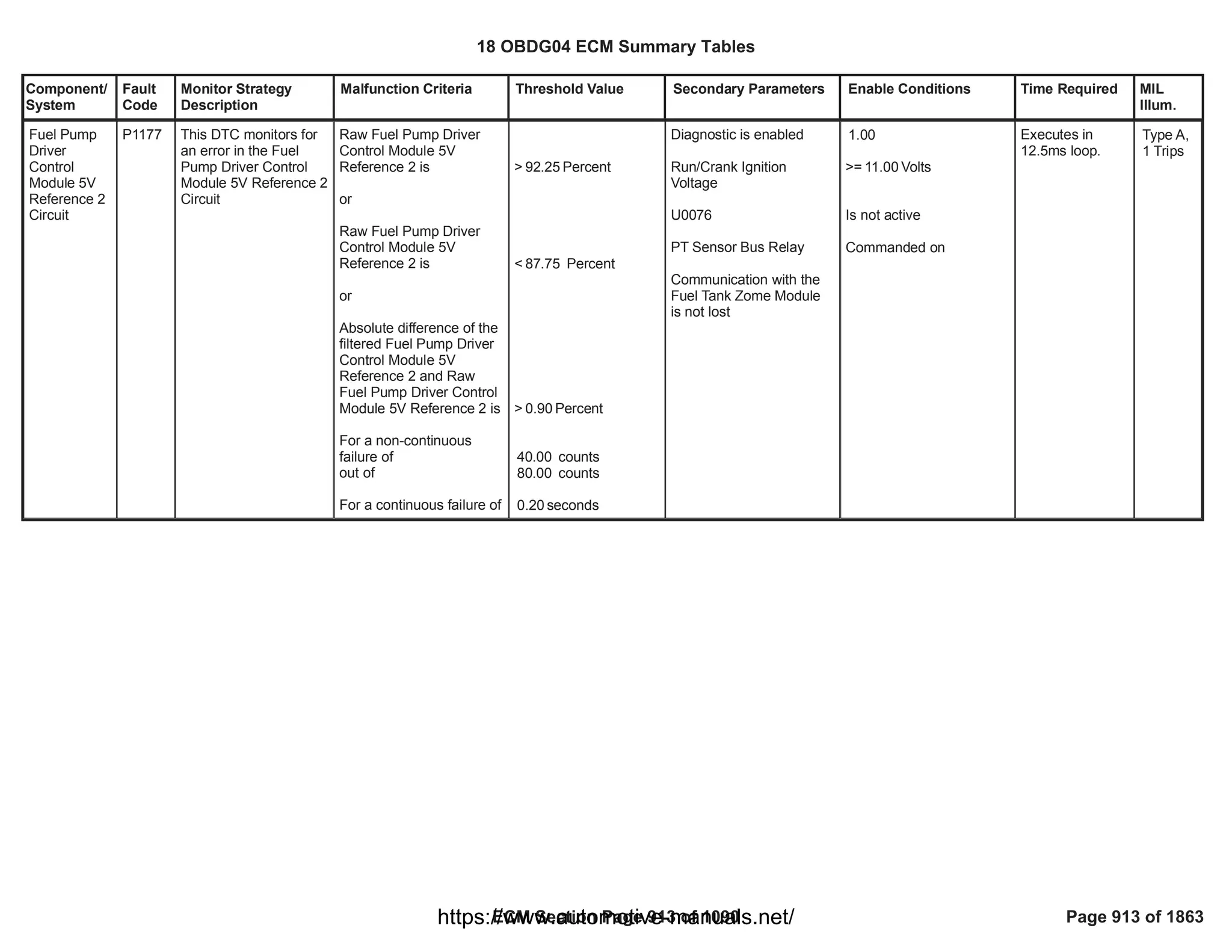
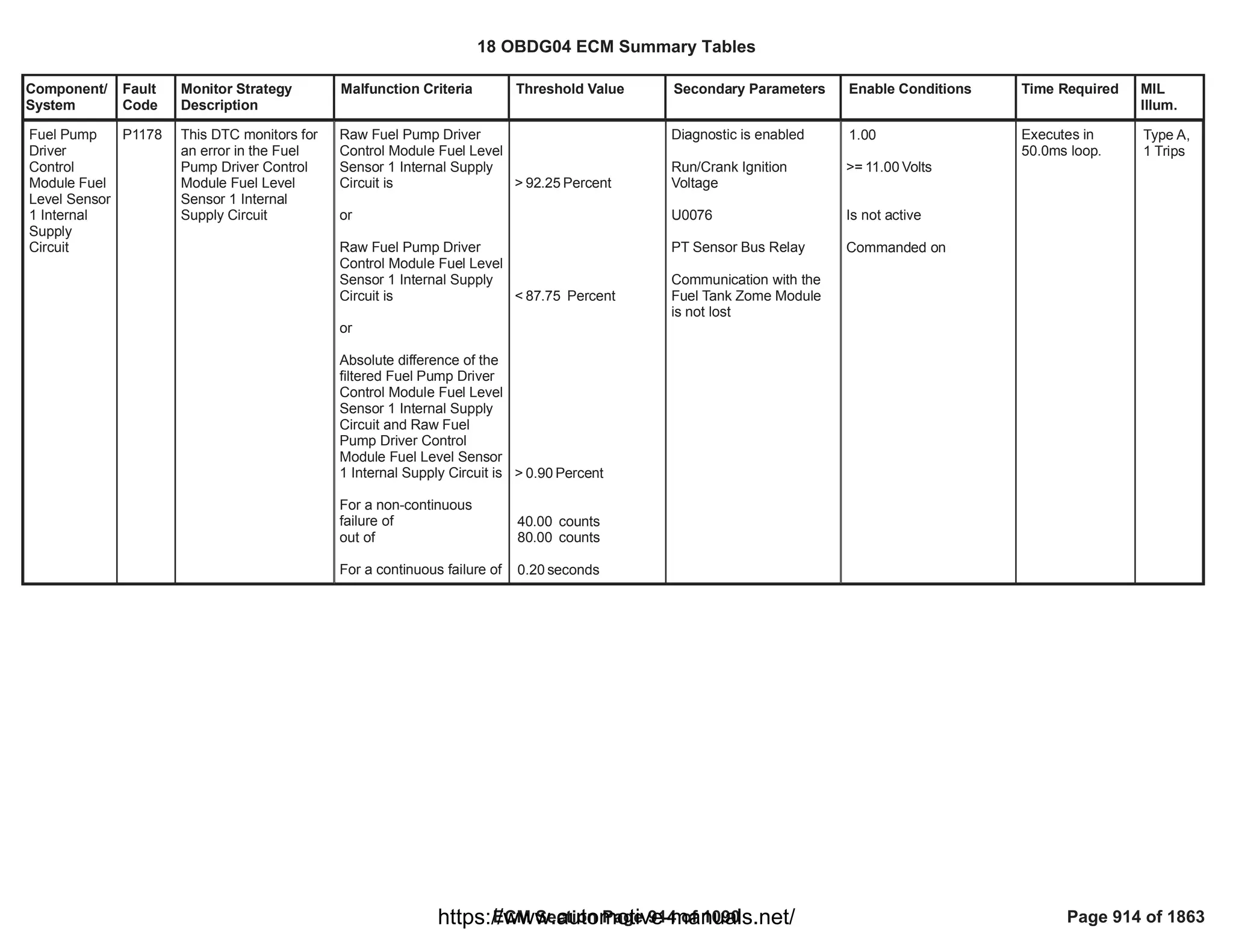

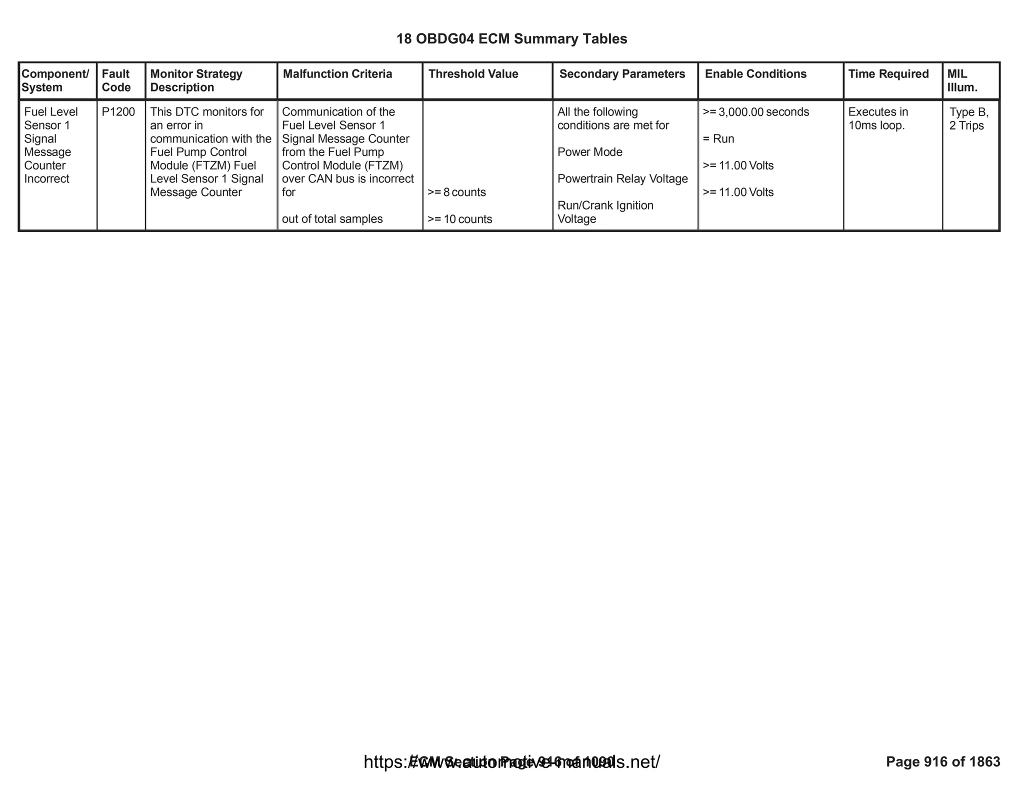
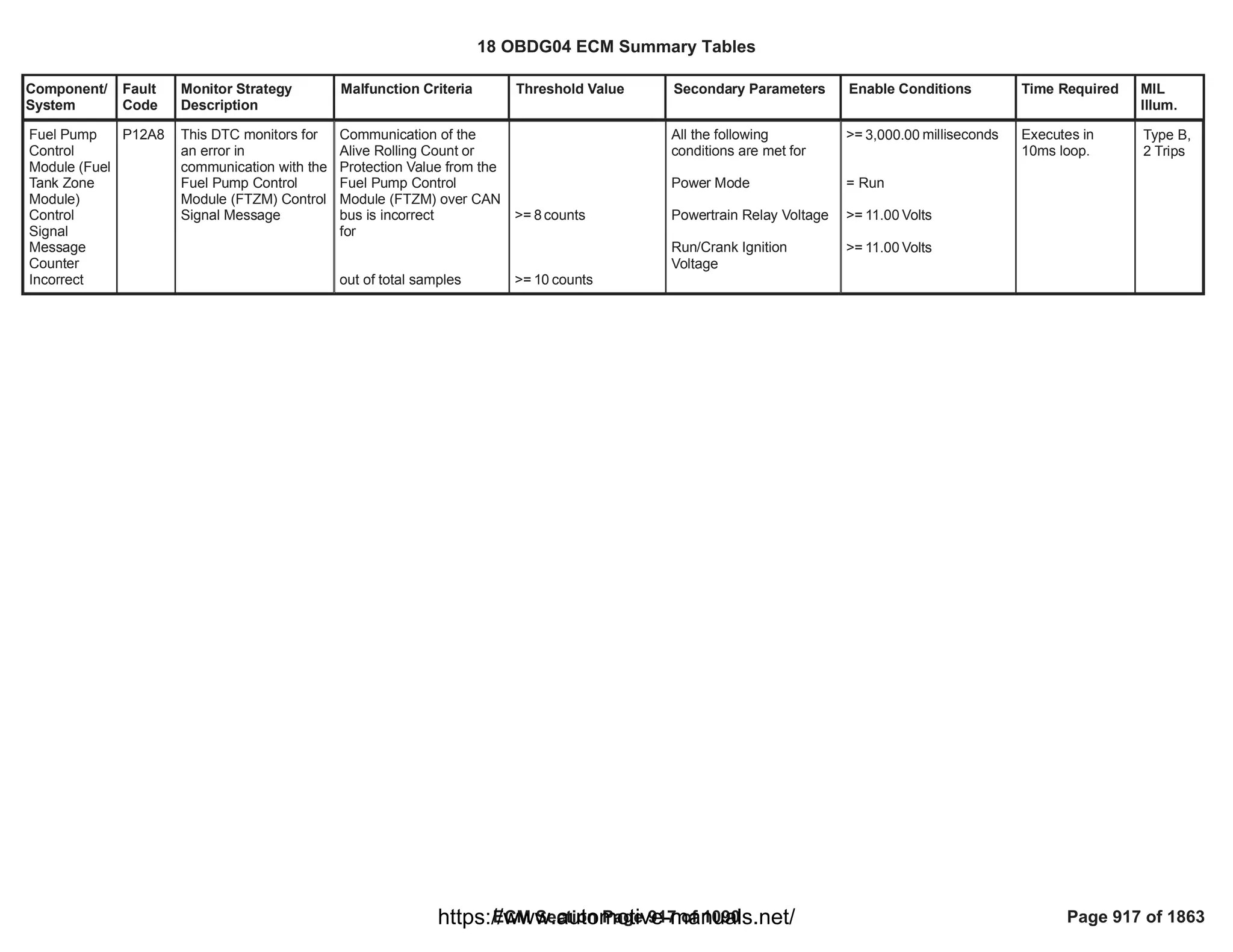
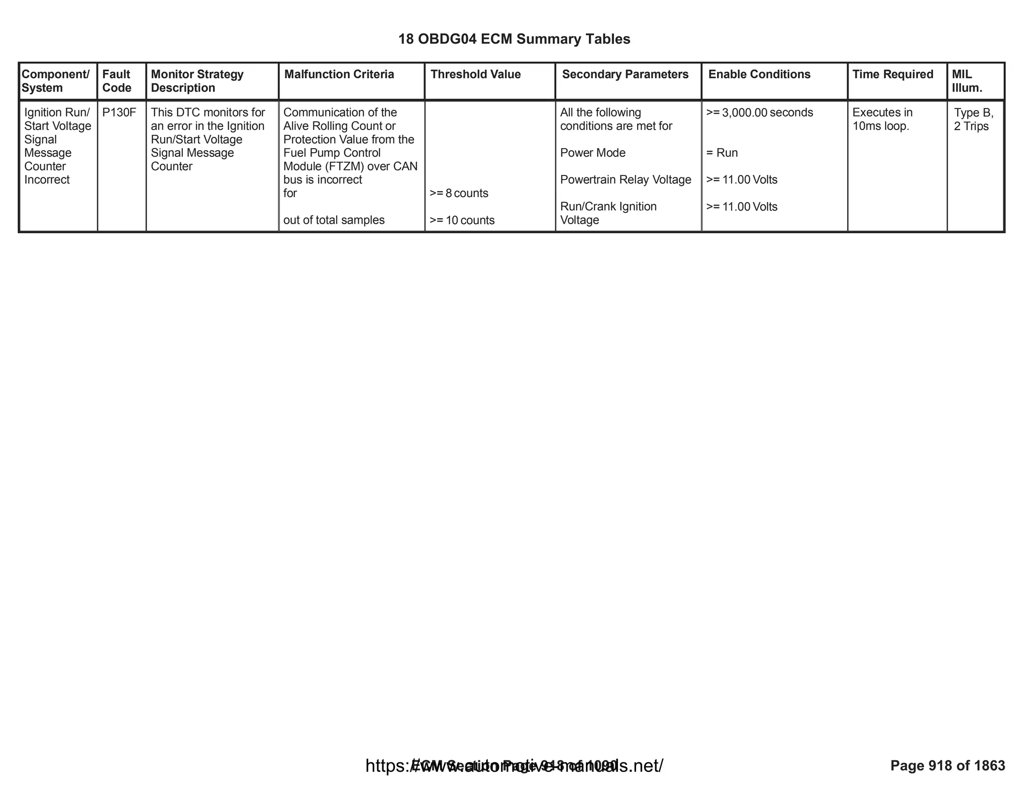

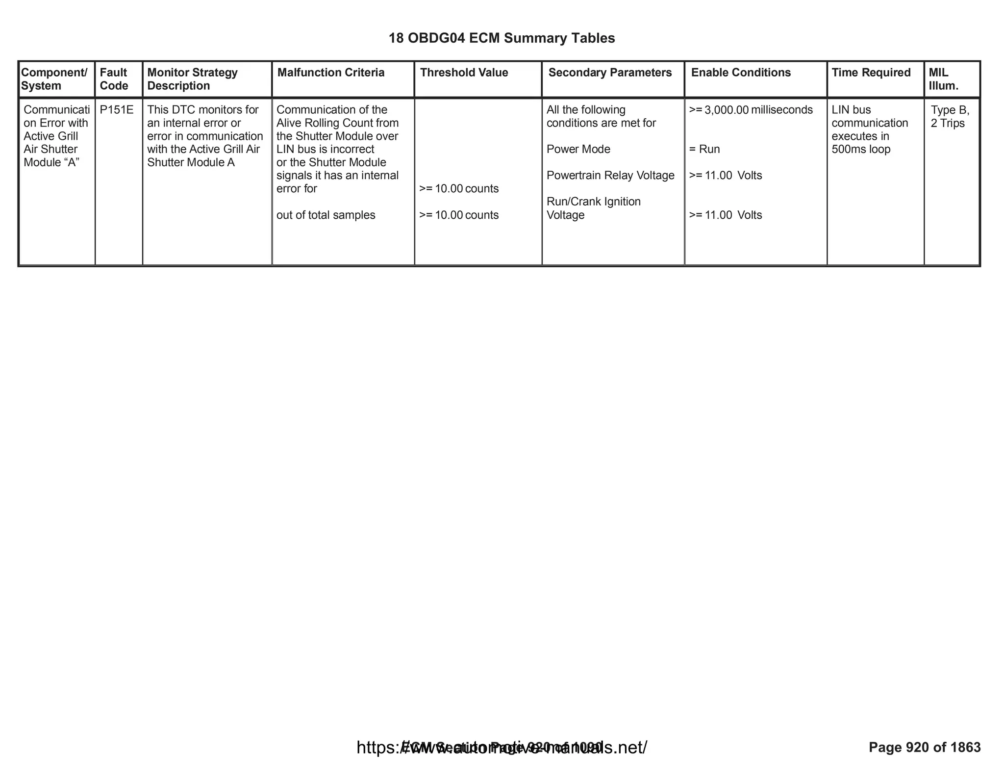


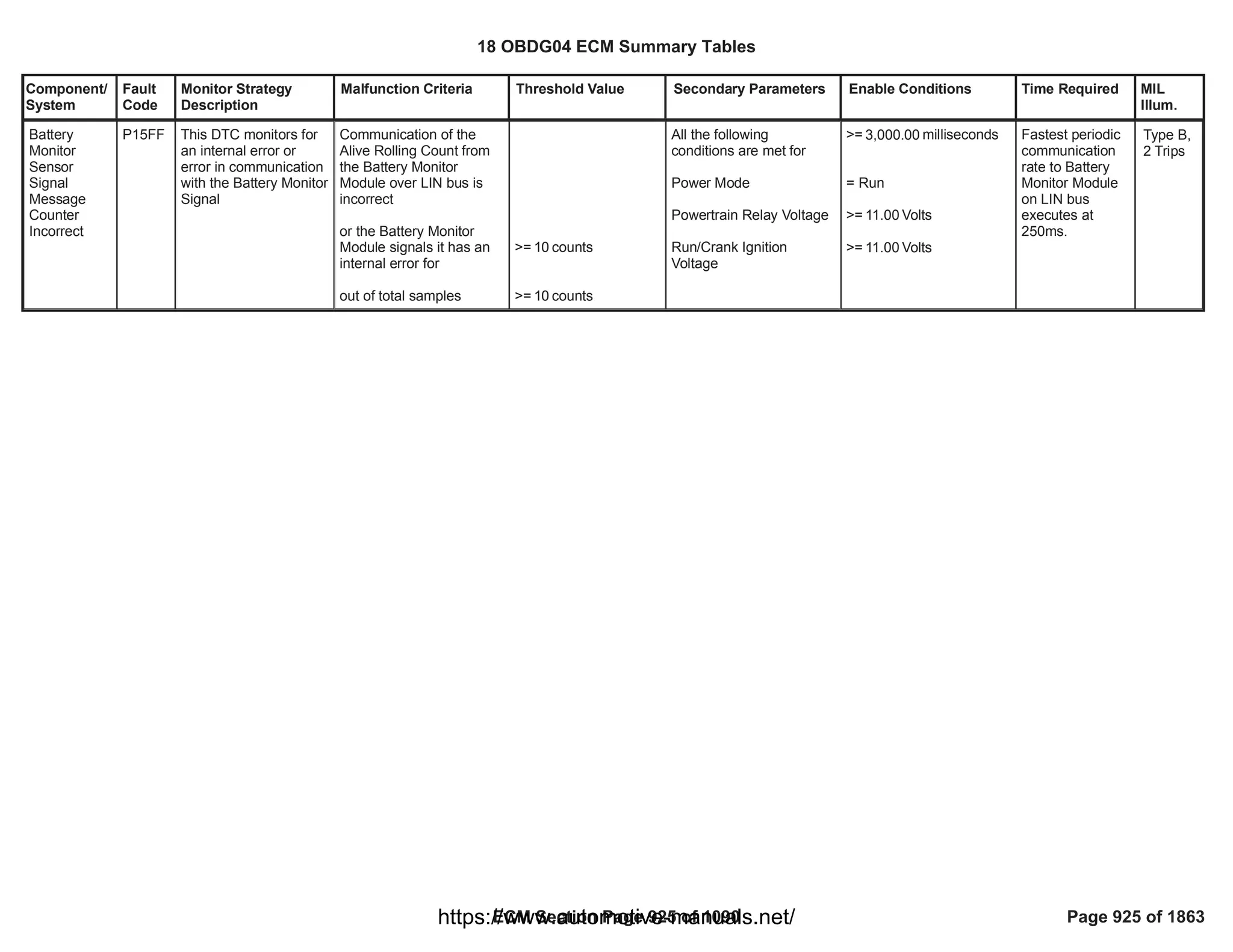


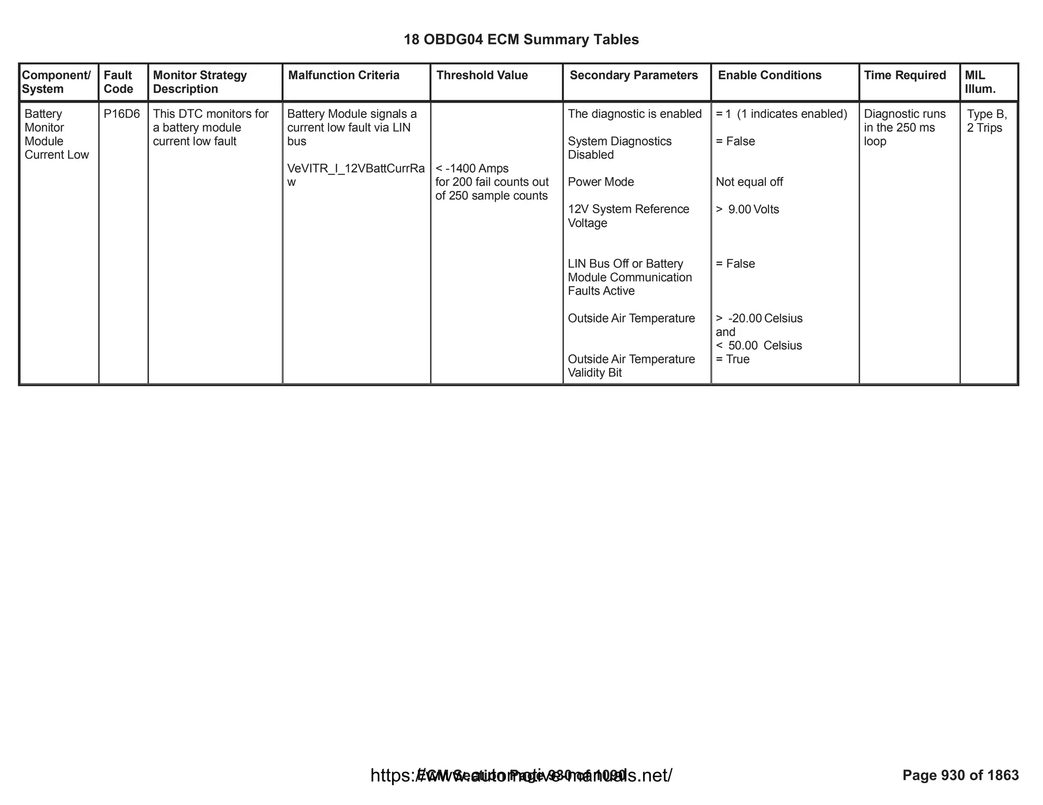
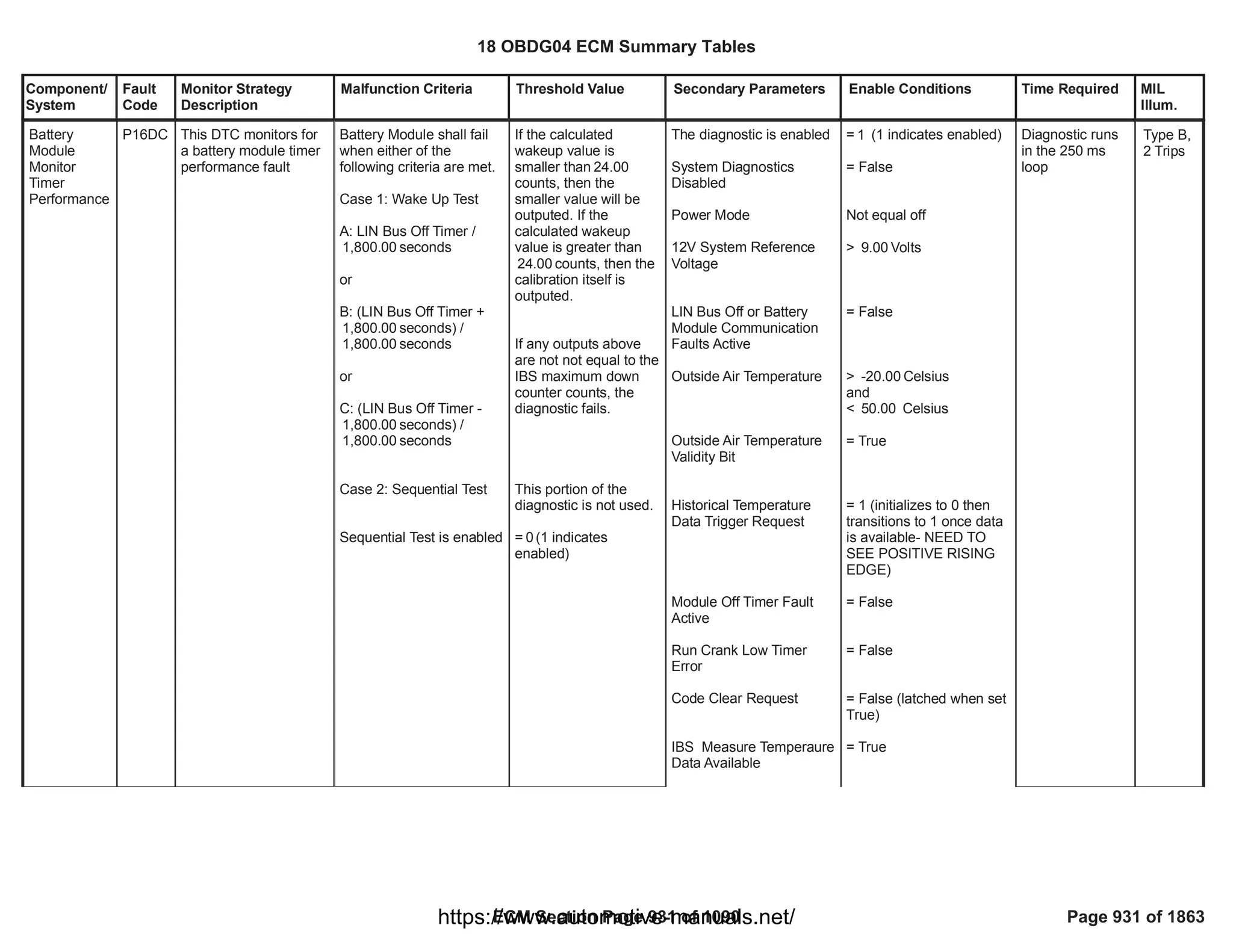
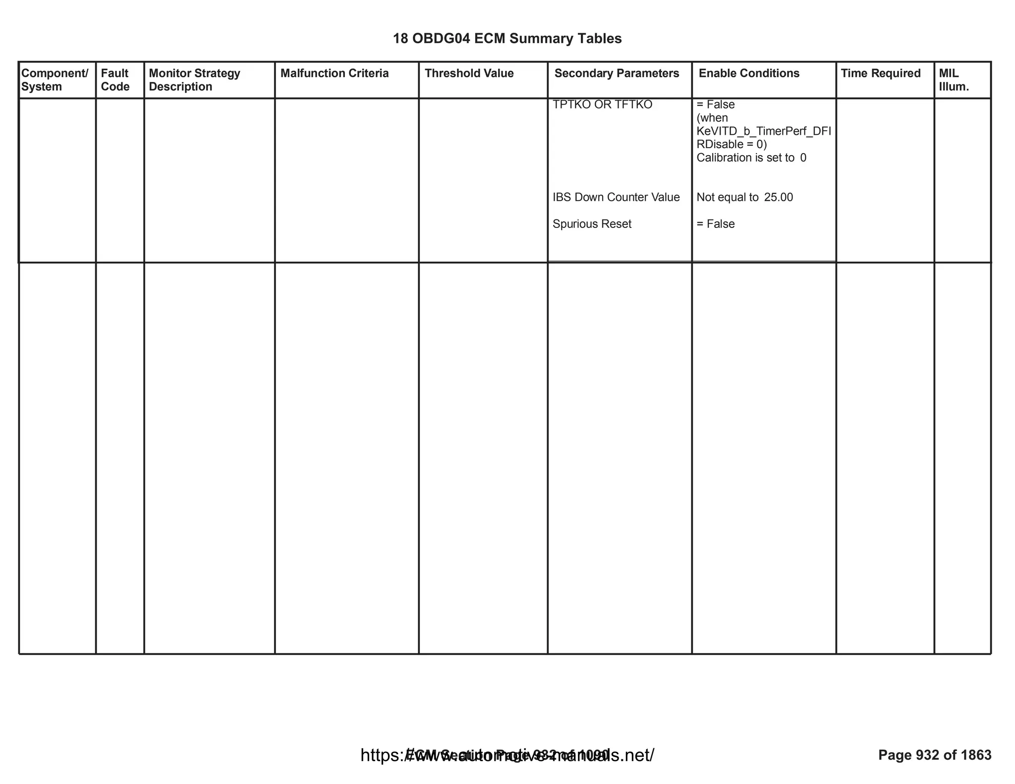


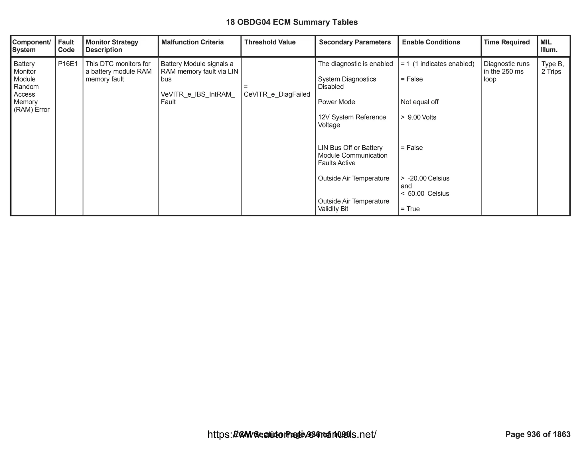
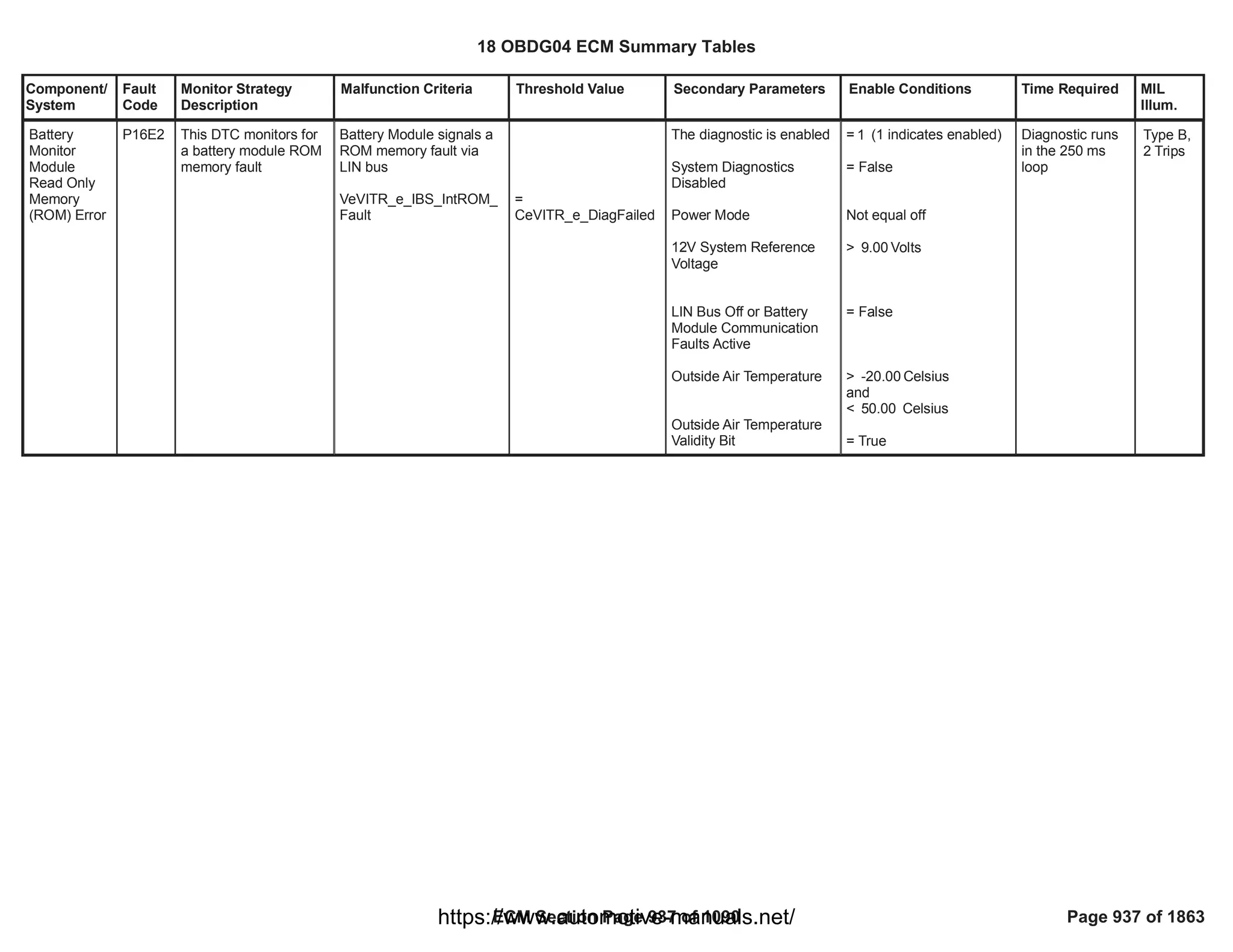
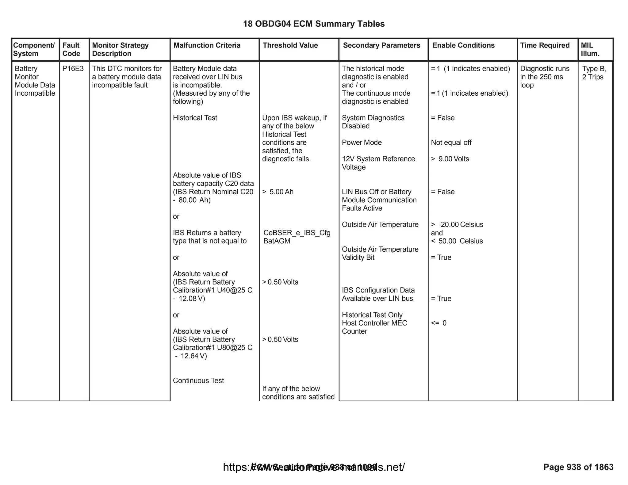
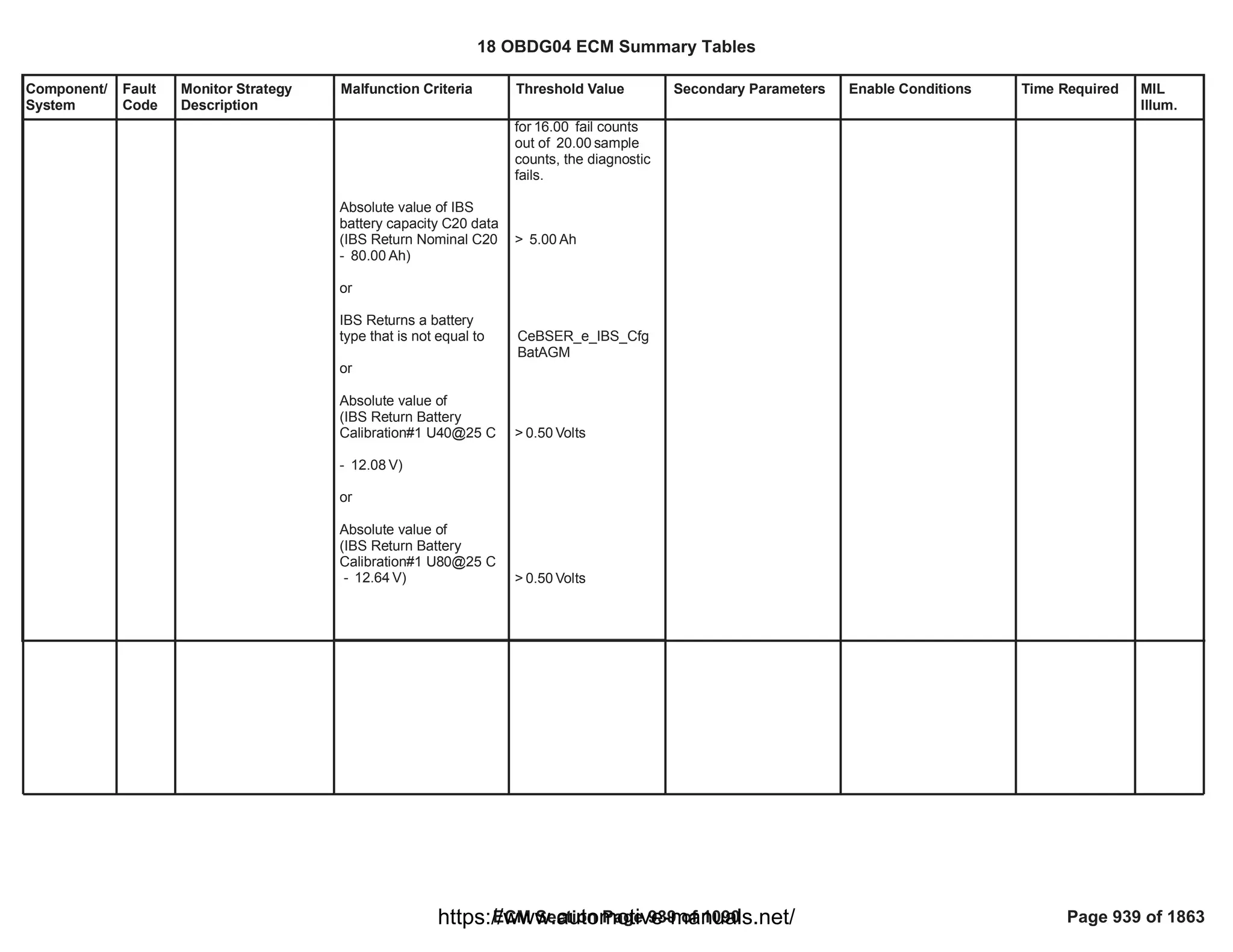
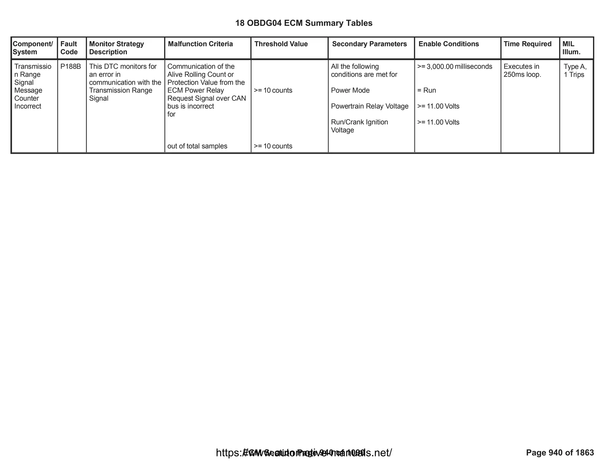
![Component/
System
Fault
Code
Monitor Strategy
Description
Malfunction Criteria Threshold Value Secondary Parameters Enable Conditions Time Required MIL
Illum.
Reductant
Level Sensor
Circuit Low
Voltage
P203C This diagnosis verifies
if an short to ground or
open circuit occurred in
the DEF level sensor
DEF level sensor raw
signal is below a
calibrated threshold
< 2.00 Test enabled by
calibration
Key on (OR engine
running)
Engine is not cranking
Battery voltage
No loss of CAN
comunication
== TRUE
1.00
> [V]
11.00
U010E, Lost
Communication With
Reductant Control Module
(SCR)
40.00
failures out of
50.00
samples
Time basis =
100ms
Type A,
1 Trips
18 OBDG04 ECM Summary Tables
ECM Section Page 941 of 1090 Page 941 of 1863
https://www.automotive-manuals.net/](https://image.slidesharecdn.com/gmcenginefaultcodesdtc1-230327071418-56d3c5bb/75/18-OBDG04-ECM-Summary-Tables-941-2048.jpg)
![Component/
System
Fault
Code
Monitor Strategy
Description
Malfunction Criteria Threshold Value Secondary Parameters Enable Conditions Time Required MIL
Illum.
Reductant
Level Sensor
Circuit High
Voltage
P203D This diagnosis verifies
that the short to battery
occurred in the DEF
level sensor
DEF level sensor raw
signal is above a
calibrated threshold
> 95.00 Test enabled by
calibration
Key on (OR engine
running)
Engine is not cranking
Battery voltage
No loss of CAN
comunication
== TRUE
1.00
> [V]
11.00
U010E, Lost
Communication With
Reductant Control Module
(SCR)
40.00
failures out of
50.00
samples
Time basis =
100ms
Type B,
2 Trips
18 OBDG04 ECM Summary Tables
ECM Section Page 942 of 1090 Page 942 of 1863
https://www.automotive-manuals.net/](https://image.slidesharecdn.com/gmcenginefaultcodesdtc1-230327071418-56d3c5bb/75/18-OBDG04-ECM-Summary-Tables-942-2048.jpg)
![Component/
System
Fault
Code
Monitor Strategy
Description
Malfunction Criteria Threshold Value Secondary Parameters Enable Conditions Time Required MIL
Illum.
Reductant
Injector
Circuit /
Open Bank 1
Unit 1
P2047 This diagnosis verifies
if a DEF dosing valve
open circuit occurred
HWIO interface
DEFMV_OPEN = Fault
VeHWIO_e_DEFMV_
Open ==
CeSCRR_e_Fault
Test enabled by
calibration
Key on (OR engine
running)
Engine is not cranking
Battery voltage
HWIO interface
DEFMV_OPEN different
from INDETERMINATE
1.00
> [V]
11.00
30.00
failures out of
60.00
samples
Time basis =
100ms
Type A,
1 Trips
18 OBDG04 ECM Summary Tables
ECM Section Page 943 of 1090 Page 943 of 1863
https://www.automotive-manuals.net/](https://image.slidesharecdn.com/gmcenginefaultcodesdtc1-230327071418-56d3c5bb/75/18-OBDG04-ECM-Summary-Tables-943-2048.jpg)
![Component/
System
Fault
Code
Monitor Strategy
Description
Malfunction Criteria Threshold Value Secondary Parameters Enable Conditions Time Required MIL
Illum.
Reductant
Injector
Circuit Low
Bank 1 Unit
1
P2048 This diagnosis verifies
if a DEF dosing valve
low side short to
ground occurred
HWIO interface
DEFMV_GROUND_SHO
RT = Fault
VeHWIO_e_DEFMV_
Gsht ==
CeSCRR_e_Fault
Test enabled by
calibration
Key on (OR engine
running)
Engine is not cranking
Battery voltage
HWIO interface
DEFMV_GROUND_SHO
RT different from
INDETERMINATE
1.00
> [V]
11.00
30.00
failures out of
60.00
samples
Time basis =
100ms
Type A,
1 Trips
18 OBDG04 ECM Summary Tables
ECM Section Page 944 of 1090 Page 944 of 1863
https://www.automotive-manuals.net/](https://image.slidesharecdn.com/gmcenginefaultcodesdtc1-230327071418-56d3c5bb/75/18-OBDG04-ECM-Summary-Tables-944-2048.jpg)
![Component/
System
Fault
Code
Monitor Strategy
Description
Malfunction Criteria Threshold Value Secondary Parameters Enable Conditions Time Required MIL
Illum.
Reductant
Injector
Circuit High
Bank 1 Unit
1
P2049 This diagnosis verifies
if a DEF dosing valve
low side short to
battery occurred
HWIO interface
DEFMV_POWER_SHOR
T = Fault
VeHWIO_e_DEFMV_P
sht ==
CeSCRR_e_Fault
Test enabled by
calibration
Key on (OR engine
running)
Engine is not cranking
Battery voltage
HWIO interface
DEFMV_ENABLE_POWE
R_SHORT different from
INDETERMINATE
1.00
> [V]
11.00
30.00
failures out of
60.00
samples
Time basis =
100ms
Type A,
1 Trips
18 OBDG04 ECM Summary Tables
ECM Section Page 945 of 1090 Page 945 of 1863
https://www.automotive-manuals.net/](https://image.slidesharecdn.com/gmcenginefaultcodesdtc1-230327071418-56d3c5bb/75/18-OBDG04-ECM-Summary-Tables-945-2048.jpg)
![Component/
System
Fault
Code
Monitor Strategy
Description
Malfunction Criteria Threshold Value Secondary Parameters Enable Conditions Time Required MIL
Illum.
Reductant
Pressure
Sensor
Performance
P204B This diagnosis verifies
if the DEF tank
Pressure sensor is
affected by rationality
fault (offset)
At the end of driving
cycle, with DEF line
empty and pressure
compensation phase
done, DEF pressure
sensor signal is not equal
(with tolerance) to the
ambient pressure
DEF Pressure signal
outside the range:
( ; ) [KPa]
7.50 18.50
Test enabled by
calibration
DEF dosing valve not in
fault
No electrical fault on
pressure sensor
SCR System Stand-By
recovery action not
activated
No DEF Pump Rotor Stall
fault
No DEF Pressure
Governor Deviation High
fault
DEF temperature sensor
higher than a calibrated
threshold
End of trip process
executed
SCR pressure
compensation performed
during afterrun
DEF metering valve
HWIO interface provides
INDETERMINATE OR
NO-FAULT during After-
Run state
1.00
==
SCR_DEFMV_FA
FALSE
==
SCR_DEFPS_FA
FALSE
==
SCR_DEFPM_FA
FALSE
SCR_PresGovDvtnHiFA
== FALSE
> -7.00
160.00
failures out of
200.00
samples
Time basis =
25ms
Type A,
1 Trips
18 OBDG04 ECM Summary Tables
ECM Section Page 946 of 1090 Page 946 of 1863
https://www.automotive-manuals.net/](https://image.slidesharecdn.com/gmcenginefaultcodesdtc1-230327071418-56d3c5bb/75/18-OBDG04-ECM-Summary-Tables-946-2048.jpg)
![Component/
System
Fault
Code
Monitor Strategy
Description
Malfunction Criteria Threshold Value Secondary Parameters Enable Conditions Time Required MIL
Illum.
Reductant
Pressure
Sensor
Circuit Low
Voltage
P204C This diagnosis verifies
that the DEF pressure
sensor is affected by
open circuit or short
circuit to ground
The DEF pressure sensor
raw signal is a voltage,
expressed as percentage
of the sensor’s supply
voltage.
DEF pressure sensor raw
signal is below a
calibrated threshold
< [%]
5.00
Test enabled by
calibration
Battery voltage > 11V
Key on
Engine is not cranking
== TRUE
1.00
> [V]
11.00
100.00
failures out of
125.00
samples
Time basis =
25ms
Type A,
1 Trips
18 OBDG04 ECM Summary Tables
ECM Section Page 948 of 1090 Page 948 of 1863
https://www.automotive-manuals.net/](https://image.slidesharecdn.com/gmcenginefaultcodesdtc1-230327071418-56d3c5bb/75/18-OBDG04-ECM-Summary-Tables-948-2048.jpg)
![Component/
System
Fault
Code
Monitor Strategy
Description
Malfunction Criteria Threshold Value Secondary Parameters Enable Conditions Time Required MIL
Illum.
Reductant
Pressure
Sensor
Circuit High
Voltage
P204D This diagnosis verifies
that the DEF pressure
sensor is affected by
short circuit to battery
The DEF pressure sensor
raw signal is a voltage,
expressed as percentage
of the sensor’s supply
voltage.
DEF pressure sensor raw
signal is above a
calibrated threshold
> [%]
98.00
Test enabled by
calibration
Battery voltage > 11V
Key on
Engine is not cranking
== TRUE
1.00
> [V]
11.00
100.00
failures out of
125.00
Time basis =
25ms
Type A,
1 Trips
18 OBDG04 ECM Summary Tables
ECM Section Page 949 of 1090 Page 949 of 1863
https://www.automotive-manuals.net/](https://image.slidesharecdn.com/gmcenginefaultcodesdtc1-230327071418-56d3c5bb/75/18-OBDG04-ECM-Summary-Tables-949-2048.jpg)
![Component/
System
Fault
Code
Monitor Strategy
Description
Malfunction Criteria Threshold Value Secondary Parameters Enable Conditions Time Required MIL
Illum.
Reductant
Tank
Temperature
Sensor
Performance
P205B This diagnosis verifies
that the DEF tank
temperature sensor is
affected by rationality
fault (gain or offset)
Difference between
temperature sensor signal
and system average
temperature (provided by
the Exhaust Gas
Temperature sensors) is
greater than a calibrated
threshold
> 35.00
Test enabled by
calibration
Battery voltage
Key on (OR engine
running)
No loss of CAN
comunication
Average exhaust gas
temperature available
or not available for a time
Engine speed = 0 rpm
No electrical fault on DEF
temperature sensor
Time elapsed since last
key off
Tank Refill is not detected
DEF temperature sensor
signal is not outside the
DEF freezing temperature
range (with tollerance).
Test not performed in this
driving cycle
No electrical malfunction
detected:
== TRUE
1.00
> [V]
11.00
U010E, Lost
Communication With
Reductant Control Module
(SCR)
< s
8
==
SCR_DEFTS_FA
FALSE
> 28,800.00
[( - ) ; (
-90.00 1.00 -90.00
+ )] [°C]
1.00
,
SCR_DEFTS_ElecHiErr
SCR_DEFTS_ElecLoErr
8.00
failures out of
10.00
samples
Time basis =
500ms
Type A,
1 Trips
18 OBDG04 ECM Summary Tables
ECM Section Page 950 of 1090 Page 950 of 1863
https://www.automotive-manuals.net/](https://image.slidesharecdn.com/gmcenginefaultcodesdtc1-230327071418-56d3c5bb/75/18-OBDG04-ECM-Summary-Tables-950-2048.jpg)
![Component/
System
Fault
Code
Monitor Strategy
Description
Malfunction Criteria Threshold Value Secondary Parameters Enable Conditions Time Required MIL
Illum.
Reductant
Tank
Temperature
Sensor
Circuit Low
Voltage
P205C This diagnosis verifies
that the DEF tank
temperature sensor is
affected by open circuit
or short circuit to
ground
The DEF tank
temperature sensor raw
output is a resistance
expressed in [ohm]
DEF temperature sensor
raw signal is below a
calibrated threshold
< [ohm]
200.00
Test enabled by
calibration
Battery voltage
Key on (OR engine
running)
Engine is not cranking
No loss of CAN
comunication
DEF Tank heater not in
fault
1.00
> [V]
11.00
U010E, Lost
Communication With
Reductant Control Module
(SCR)
==
SCR_DEFTH_FA
FALSE
8.00
failures out of
10.00
samples
Time basis =
500ms
Type A,
1 Trips
18 OBDG04 ECM Summary Tables
ECM Section Page 951 of 1090 Page 951 of 1863
https://www.automotive-manuals.net/](https://image.slidesharecdn.com/gmcenginefaultcodesdtc1-230327071418-56d3c5bb/75/18-OBDG04-ECM-Summary-Tables-951-2048.jpg)
![Component/
System
Fault
Code
Monitor Strategy
Description
Malfunction Criteria Threshold Value Secondary Parameters Enable Conditions Time Required MIL
Illum.
Reductant
Tank
Temperature
Sensor
Circuit High
Voltage
P205D This diagnosis verifies
that the DEF tank
temperature sensor is
affected by short circuit
to battery
The DEF tank
temperature sensor raw
output is a resistance
expressed in [ohm]
DEF temperature sensor
raw signal is above a
calibrated threshold
> 60,000.00 Test enabled by
calibration
Battery voltage
Key on (OR engine
running)
Engine is not cranking
No loss of CAN
comunication
DEF Tank heater not in
fault
Defrost phase is
completed
1.00
> [V]
11.00
U010E, Lost
Communication With
Reductant Control Module
(SCR)
==
SCR_DEFTH_FA
FALSE
8.00
failures out of
10.00
samples
Time basis =
500ms
Type A,
1 Trips
18 OBDG04 ECM Summary Tables
ECM Section Page 952 of 1090 Page 952 of 1863
https://www.automotive-manuals.net/](https://image.slidesharecdn.com/gmcenginefaultcodesdtc1-230327071418-56d3c5bb/75/18-OBDG04-ECM-Summary-Tables-952-2048.jpg)
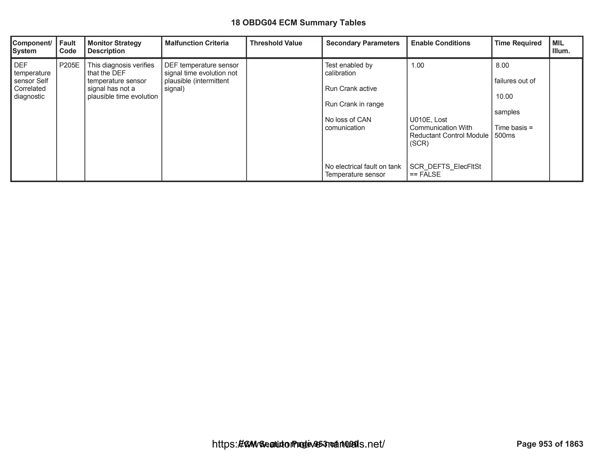
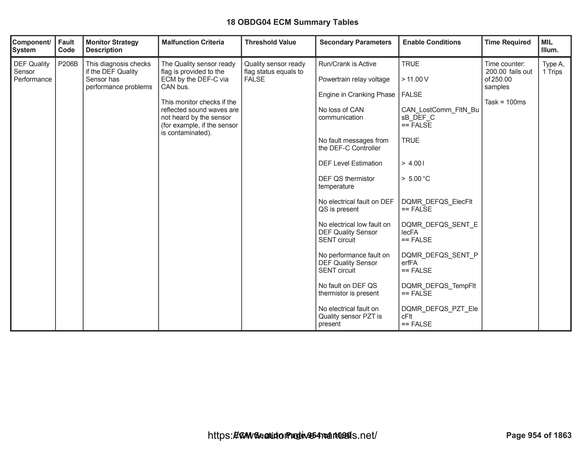
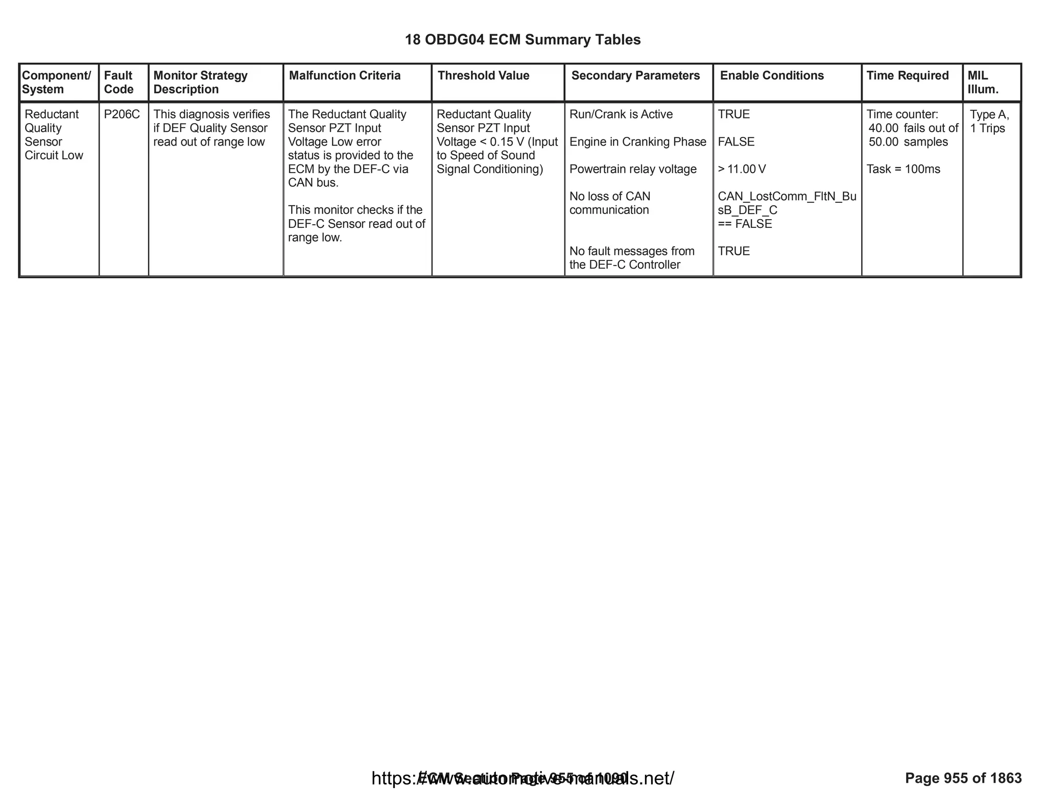
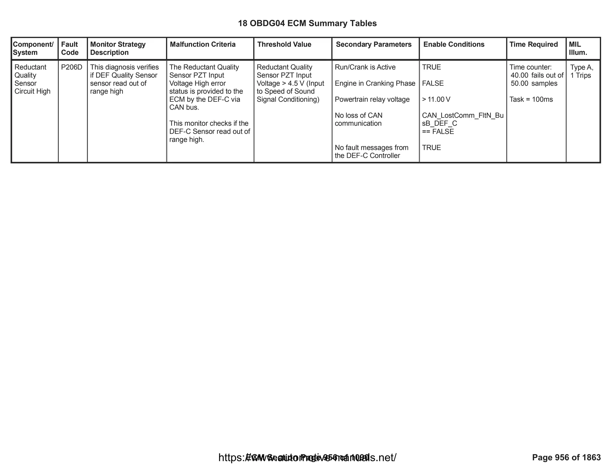
![Component/
System
Fault
Code
Monitor Strategy
Description
Malfunction Criteria Threshold Value Secondary Parameters Enable Conditions Time Required MIL
Illum.
Reductant
Pump
Control
Circuit
P208A This diagnosis verifies
that the DEF pump
phases are open
Motor Pump Phase Open
Error status provided by
DEF control module ==
FAULT
Test enabled by
calibration
Battery voltage
Key on (OR engine
running)
Engine is not cranking
No loss of CAN
comunication
Motor Pump Phase Open
Error status provided by
DEF control module
different from
indeterminate
1.00
> [V]
11.00
U010E, Lost
Communication With
Reductant Control Module
(SCR)
32.00
failures out of
40.00
samples
Time basis =
100ms
Type A,
1 Trips
18 OBDG04 ECM Summary Tables
ECM Section Page 957 of 1090 Page 957 of 1863
https://www.automotive-manuals.net/](https://image.slidesharecdn.com/gmcenginefaultcodesdtc1-230327071418-56d3c5bb/75/18-OBDG04-ECM-Summary-Tables-957-2048.jpg)
![Component/
System
Fault
Code
Monitor Strategy
Description
Malfunction Criteria Threshold Value Secondary Parameters Enable Conditions Time Required MIL
Illum.
Reductant
Pump
Control
Circuit Low
Voltage
P208C This diagnosis verifies
that the DEF pump
phases are shorted to
ground
Motor Pump Phase
Shorted To Ground Error
status provided by DEF
control module == FAULT
VeSCRR_e_PmpMtrS
hrtToGND==FAULT
Test enabled by
calibration
Battery voltage
Key on (OR engine
running)
Engine is not cranking
No loss of CAN
comunication
Motor Pump Phase
Shorted To Ground Error
status provided by DEF
control module different
from indeterminate
1.00
> [V]
11.00
(VeLVTR_b_PT_RelayInR
ange== TRUE)
VePMDR_b_RunCrankAc
tive==TRUE
VeEMDR_b_EngModeCra
nk == FALSE
U010E, Lost
Communication With
Reductant Control Module
(SCR)
(GetCANR_b_LostComm
_FltN= FALSE)
VeSCRR_e_PmpMtrShrtT
oGND != Indeterminate
20.00
failures out of
25.00
samples
Time basis =
100ms
Type A,
1 Trips
18 OBDG04 ECM Summary Tables
ECM Section Page 958 of 1090 Page 958 of 1863
https://www.automotive-manuals.net/](https://image.slidesharecdn.com/gmcenginefaultcodesdtc1-230327071418-56d3c5bb/75/18-OBDG04-ECM-Summary-Tables-958-2048.jpg)
![Component/
System
Fault
Code
Monitor Strategy
Description
Malfunction Criteria Threshold Value Secondary Parameters Enable Conditions Time Required MIL
Illum.
Reductant
Pump
Control
Circuit High
Voltage
P208D This diagnosis verifies
that the DEF pump
phases are shorted to
battery
Motor Pump Phase
Shorted To Battery Error
status provided by DEF
control module == FAULT
Test enabled by
calibration
Battery voltage
Key on (OR engine
running)
Engine is not cranking
No loss of CAN
comunication
Motor Pump Phase
Shorted To Battery Error
status provided by DEF
control module different
from indeterminate
1.00
> [V]
11.00
U010E, Lost
Communication With
Reductant Control Module
(SCR)
20.00
failures out of
25.00
samples
Time basis =
100ms
Type A,
1 Trips
18 OBDG04 ECM Summary Tables
ECM Section Page 959 of 1090 Page 959 of 1863
https://www.automotive-manuals.net/](https://image.slidesharecdn.com/gmcenginefaultcodesdtc1-230327071418-56d3c5bb/75/18-OBDG04-ECM-Summary-Tables-959-2048.jpg)
![Component/
System
Fault
Code
Monitor Strategy
Description
Malfunction Criteria Threshold Value Secondary Parameters Enable Conditions Time Required MIL
Illum.
Reductant
Heater 1
Control
Circuit
P20B9 This diagnosis verifies
if the DEF tank heater
is affected by open
circuit
Tank Heater Open circuit
status == FAULT
Test enabled by
calibration
Temperature used by the
heating strategy to switch
on the heaters < threshold
Battery voltage
Key on (OR engine
running)
Engine is not cranking
No loss of CAN
comunication
DEF Temperature sensor
not in fault
Open circuit status
provided by DEF control
module different from
indeterminate
1.00
< 60.00
> [V]
11.00
U010E, Lost
Communication With
Reductant Control Module
(SCR)
==
SCR_DEFTS_FA
FALSE
8.00
failures out ofon
10.00
samples
Time basis =
500ms
Type A,
1 Trips
18 OBDG04 ECM Summary Tables
ECM Section Page 960 of 1090 Page 960 of 1863
https://www.automotive-manuals.net/](https://image.slidesharecdn.com/gmcenginefaultcodesdtc1-230327071418-56d3c5bb/75/18-OBDG04-ECM-Summary-Tables-960-2048.jpg)
![Component/
System
Fault
Code
Monitor Strategy
Description
Malfunction Criteria Threshold Value Secondary Parameters Enable Conditions Time Required MIL
Illum.
DEF tank
heater
plausibility
check
P20BA This diagnosis verify
thet the DEF tank
heater resistance value
is not plausible
DEF tank heater
resistance not plausible
(too different from the
nominal one)
DEF tank heater
resistance outside the
range
( ; ) [ohm]
1.05 1.93
Test enabled by
calibration
Battery voltage
Key on (OR engine
running)
Engine is not cranking
No SCR Power Module
CAN loss of
communication
No electrical faults
affecting the tank heater
Heating strategy is
requesting the Heater to
be activated
Time passed since heater
activation > threshold
Tank heater supply under-
voltage fault not present
1.00
> [V]
11.00
U010E, Lost
Communication With
Reductant Control Module
(SCR)
SCR_DEFTH_ElecFltSt
== FALSE
> [s]
1.00
SCR_TankHeatSplyVoltF
A
== FALSE
10.00
failures out of
12.00
samples
Time basis =
500ms
18 OBDG04 ECM Summary Tables
ECM Section Page 961 of 1090 Page 961 of 1863
https://www.automotive-manuals.net/](https://image.slidesharecdn.com/gmcenginefaultcodesdtc1-230327071418-56d3c5bb/75/18-OBDG04-ECM-Summary-Tables-961-2048.jpg)
![Component/
System
Fault
Code
Monitor Strategy
Description
Malfunction Criteria Threshold Value Secondary Parameters Enable Conditions Time Required MIL
Illum.
Reductant
Heater 1
Control
Circuit Low
Voltage
P20BB This diagnosis verifies
if the DEF tank heater
is affected by short
circuit to ground
Tank Heater Short to
Ground Low Side / High
Side status == FAULT
Test enabled by
calibration
Temperature used by the
heating strategy to switch
on the heaters < threshold
Battery voltage
Key on (OR engine
running)
Engine is not cranking
No loss of CAN
comunication
DEF Temperature sensor
not in fault
Short to Ground Low
Side / High Side status
provided by DEF control
module different from
indeterminate
1.00
< 60.00
> [V]
11.00
U010E, Lost
Communication With
Reductant Control Module
(SCR)
==
SCR_DEFTS_FA
FALSE
8.00
failures out of
10.00
samples
Time basis =
500ms
Type A,
1 Trips
18 OBDG04 ECM Summary Tables
ECM Section Page 962 of 1090 Page 962 of 1863
https://www.automotive-manuals.net/](https://image.slidesharecdn.com/gmcenginefaultcodesdtc1-230327071418-56d3c5bb/75/18-OBDG04-ECM-Summary-Tables-962-2048.jpg)
![Component/
System
Fault
Code
Monitor Strategy
Description
Malfunction Criteria Threshold Value Secondary Parameters Enable Conditions Time Required MIL
Illum.
Reductant
Heater 1
Control
Circuit High
Voltage
P20BC This diagnosis verifies
if the DEF tank heater
is affected by short
circuit to battery
Tank Heater Short to
Battery Low Side / High
Side status == FAULT
Test enabled by
calibration
Temperature used by the
heating strategy to switch
on the heaters < threshold
Battery voltage
Key on (OR engine
running)
Engine is not cranking
No loss of CAN
comunication
DEF Temperature sensor
not in fault
Short to Battery Low
Side / High Side status
provided by DEF control
module different from
indeterminate
1.00
< 60.00
> [V]
11.00
U010E, Lost
Communication With
Reductant Control Module
(SCR)
==
SCR_DEFTS_FA
FALSE
8.00
failures out of
10.00
samples
Time basis =
500ms
Type A,
1 Trips
18 OBDG04 ECM Summary Tables
ECM Section Page 963 of 1090 Page 963 of 1863
https://www.automotive-manuals.net/](https://image.slidesharecdn.com/gmcenginefaultcodesdtc1-230327071418-56d3c5bb/75/18-OBDG04-ECM-Summary-Tables-963-2048.jpg)
![Component/
System
Fault
Code
Monitor Strategy
Description
Malfunction Criteria Threshold Value Secondary Parameters Enable Conditions Time Required MIL
Illum.
Reductant
Heater 2
Control
Circuit
P20BD This diagnosis verifies
if the DEF line heater is
affected by open circuit
Line Heater Open circuit
status == FAULT
Test enabled by
calibration
Temperature used by the
heating strategy to switch
on the heaters < threshold
Battery voltage
Key on (OR engine
running)
Engine is not cranking
No loss of CAN
comunication
Open circuit status
provided by DEF control
module different from
indeterminate
1.00
< 60.00
> [V]
11.00
U010E, Lost
Communication With
Reductant Control Module
(SCR)
8.00
failures out of
10.00
samples
Time basis =
500ms
Type A,
1 Trips
18 OBDG04 ECM Summary Tables
ECM Section Page 964 of 1090 Page 964 of 1863
https://www.automotive-manuals.net/](https://image.slidesharecdn.com/gmcenginefaultcodesdtc1-230327071418-56d3c5bb/75/18-OBDG04-ECM-Summary-Tables-964-2048.jpg)
![Component/
System
Fault
Code
Monitor Strategy
Description
Malfunction Criteria Threshold Value Secondary Parameters Enable Conditions Time Required MIL
Illum.
DEF line
heater
plausibility
check
P20BE This diagnosis verify
thet the DEF line
heater resistance value
is not plausible
DEF line heater
resistance value not
plausible (too different
from the nominal one)
(Heater supply voltage/
Heater Current) >
3.57
OR
(Heater supply voltage/
Heater Current) <
1.51
Test enabled by
calibration
Battery voltage
Key on (OR engine
running)
Engine is not cranking
No loss of CAN
comunication
No electrical faults
affecting the line heater
Heating strategy is
requesting the Heater to
be activated
Time since heater
activation > threshold
Line heater supply under-
voltage fault not present
1.00
> [V]
11.00
U010E, Lost
Communication With
Reductant Control Module
(SCR)
SCR_DEFLH_ElecFltSt
==FALSE
VeSCRR_b_HeatB_On
== TRUE
> 1.00
SCR_LineHeatSplyVoltFA
== FALSE
10.00
failures out of
12.00
samples
Time basis =
500ms
18 OBDG04 ECM Summary Tables
ECM Section Page 965 of 1090 Page 965 of 1863
https://www.automotive-manuals.net/](https://image.slidesharecdn.com/gmcenginefaultcodesdtc1-230327071418-56d3c5bb/75/18-OBDG04-ECM-Summary-Tables-965-2048.jpg)
![Component/
System
Fault
Code
Monitor Strategy
Description
Malfunction Criteria Threshold Value Secondary Parameters Enable Conditions Time Required MIL
Illum.
Reductant
Heater 2
Control
Circuit Low
Voltage
P20BF This diagnosis verifies
if the DEF line heater is
affected by short circuit
to ground
Line Heater Short to
Ground Low Side / High
Side status == FAULT
Test enabled by
calibration
Temperature used by the
heating strategy to switch
on the heaters < threshold
Battery voltage
Key on (OR engine
running)
Engine is not cranking
No loss of CAN
comunication
Short to Ground Low
Side / High Side status
provided by DEF control
module different from
indeterminate
1.00
< 60.00
> [V]
11.00
U010E, Lost
Communication With
Reductant Control Module
(SCR)
8.00
failures out of
10.00
samples
Time basis =
500ms
Type A,
1 Trips
18 OBDG04 ECM Summary Tables
ECM Section Page 966 of 1090 Page 966 of 1863
https://www.automotive-manuals.net/](https://image.slidesharecdn.com/gmcenginefaultcodesdtc1-230327071418-56d3c5bb/75/18-OBDG04-ECM-Summary-Tables-966-2048.jpg)
![Component/
System
Fault
Code
Monitor Strategy
Description
Malfunction Criteria Threshold Value Secondary Parameters Enable Conditions Time Required MIL
Illum.
Reductant
Heater 2
Control
Circuit High
Voltage
P20C0 This diagnosis verifies
if the DEF line heater is
affected by short circuit
to battery
Line Heater Short to
Battery Low Side / High
Side status == FAULT
Test enabled by
calibration
Temperature used by the
heating strategy to switch
on the heaters < threshold
Battery voltage
Key on (OR engine
running)
Engine is not cranking
No loss of CAN
comunication
Short to Battery Low
Side / High Side status
provided by DEF control
module different from
indeterminate
1.00
< 60.00
> [V]
11.00
U010E, Lost
Communication With
Reductant Control Module
(SCR)
8.00
failures out of
10.00
samples
Time basis =
500ms
Type A,
1 Trips
18 OBDG04 ECM Summary Tables
ECM Section Page 967 of 1090 Page 967 of 1863
https://www.automotive-manuals.net/](https://image.slidesharecdn.com/gmcenginefaultcodesdtc1-230327071418-56d3c5bb/75/18-OBDG04-ECM-Summary-Tables-967-2048.jpg)
![Component/
System
Fault
Code
Monitor Strategy
Description
Malfunction Criteria Threshold Value Secondary Parameters Enable Conditions Time Required MIL
Illum.
Reductant
Pressure Too
Low
P20E8 This diagnosis verifies
that the DEF pressure
is lower than the target
value set by the control
(Test 1)
Too attemps of pressure
build up
(Test 2)
DEF pressure setpoint -
DEF measured pressure
> calibrateable threshold
(Test 1)
> 2.00
(Test 2)
> 166.00
Test enabled by
calibration
Battery voltage
Key on (OR engine
running)
Defrost complete
Motor pump rotor stall
fault not present
No fault on DEF pressure
sensor
No fault on PWM
command
No electrical fault on DEF
pump
No electrical fault on DEF
dosing valve
Motor pump is no more
green (some build
pressure attempts already
performed since the
beginning of vehicle life).
Time elapsed from the
first build up attempt
1.00
> [V]
11.00
==
SCR_PmpRtrStlFA
FALSE
==
SCR_DEFPS_FA
FALSE
SCR_DEF_PumpCmdFA
== FALSE
==
SCR_DEFPM_FA
FALSE
==
SCR_DEFMV_FA
FALSE
> [s]
1,200.00
40.00
failures out of
50.00
samples
Time basis =
500ms
Type A,
1 Trips
18 OBDG04 ECM Summary Tables
ECM Section Page 968 of 1090 Page 968 of 1863
https://www.automotive-manuals.net/](https://image.slidesharecdn.com/gmcenginefaultcodesdtc1-230327071418-56d3c5bb/75/18-OBDG04-ECM-Summary-Tables-968-2048.jpg)
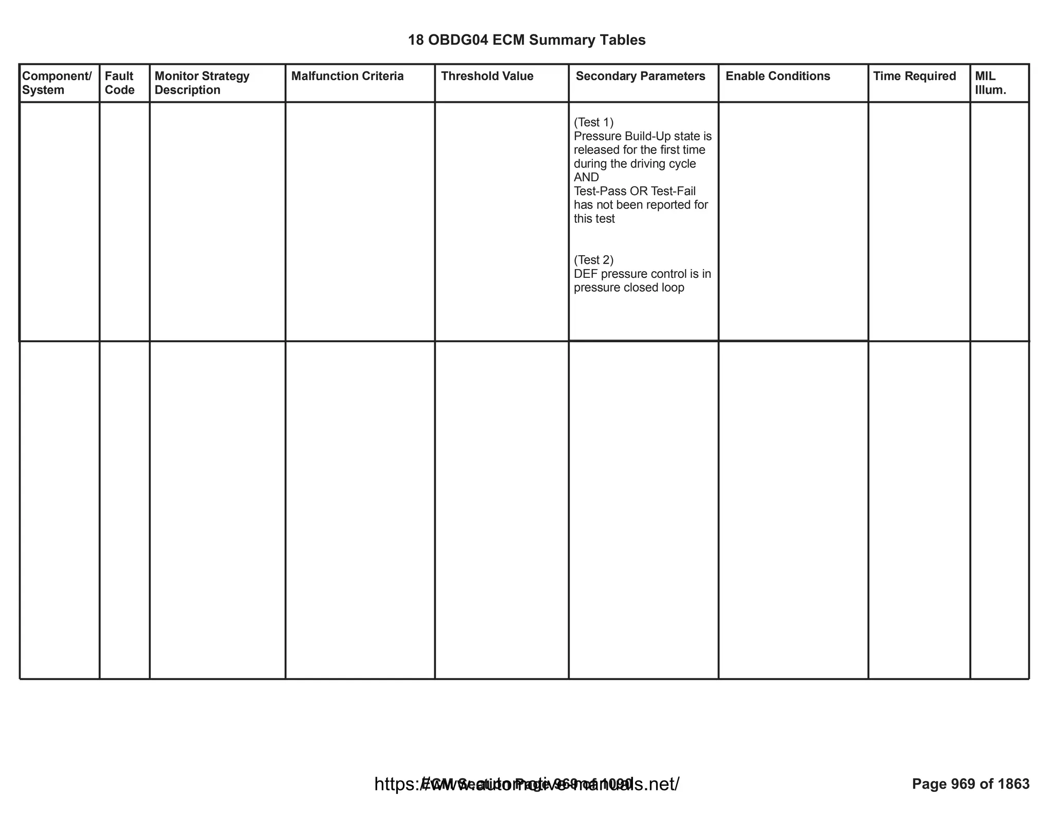
![Component/
System
Fault
Code
Monitor Strategy
Description
Malfunction Criteria Threshold Value Secondary Parameters Enable Conditions Time Required MIL
Illum.
Reductant
Pressure Too
High
P20E9 This diagnosis verifies
that the DEF pressure
in the dosing line is too
high
Difference between "DEF
line pressure" and "DEF
line pressure set point" >
Threshold
AND
Pump rotor speed <
Threshold
> 150.00
< 3,200.00
Test enabled by
calibration
Battery voltage
Battery voltage
Key on (OR engine
running)
DEF pressure sensor not
in fault
PWM_pump_command
not in fault
DEF pressure control
status equal to “Closed
loop control”
DEF motor pump not in
fault
Pump motor speed signal
valid on CAN
1.00
> [V]
11.00
==
SCR_DEFPS_FA
FALSE
SCR_DEF_PumpCmdFA
== FALSE
VeSCRC_e_SCR_PresSt
ate ==
CeSCRC_e_PresCntrlCL
C
SCR_DEFPM_FA
100.00
failures out of
125.00
samples
Time basis =
25ms
Type A,
1 Trips
18 OBDG04 ECM Summary Tables
ECM Section Page 970 of 1090 Page 970 of 1863
https://www.automotive-manuals.net/](https://image.slidesharecdn.com/gmcenginefaultcodesdtc1-230327071418-56d3c5bb/75/18-OBDG04-ECM-Summary-Tables-970-2048.jpg)
![Component/
System
Fault
Code
Monitor Strategy
Description
Malfunction Criteria Threshold Value Secondary Parameters Enable Conditions Time Required MIL
Illum.
SCR NOx
Catalyst
Efficiency
Below
Threshold
Bank 1
P20EE The diagnosis checks if
there is a malfunction
in the SCR NOx
conversion system
measuring its SCR
NOx conversion
efficiency.
SCR NOx conversion
efficiency is evaluated
by two NOx sensors
(upstream &
downstream SCR).
The monitoring is
executed by comparing
measured NOx
conversion efficiency
and expected NOx
conversion efficiency:
- Measured NOx
conversion efficiency is
calculated as
Ș_Eff_Msrd
= 1 - [ œ
NOx_Dwn_
Msrd / œ
NOx_Up_M
srd]
- Expected NOx
conversion efficiency is
evaluated as
Ș_Eff_R
ef = 1 - [ œ
NOx_Dwn_
Ref / œ
NOx_Up_M
srd]
- If EWMA feature is not
enabled ( == 0
1
[Boolean]), measured
SCR NOx conversion
efficiency (Ș_Eff_Msrd)
lower than expected one
Ș_Eff_Ref)
- If EWMA feature is
enabled ( == 1
1
[Boolean]), EWMA filtering
is applied to the difference
between measured SCR
NOx conversion efficiency
Ș_Eff_Msrd) and
expected one (Ș_Eff_Ref)
- If EWMA filter is not
enabled ( == 0
1
[Boolean]) -->
Ș_Eff_Ref
- If EWMA filter is
enabled ( == 1
1
[Boolean]) --> Fail
threshold is = 0,
Repass threshold is =
0
Test enabled by
calibration;
No active DTCs;
Debounce time elapsed
after SCR chemical model
is healed;
Debounce time elapsed
after exiting from
transient dosing forced by
remedial action
(conditions active only if
Market USA_CARB);
Diagnostic system not
disabled;
Test not yet executed on
current key cycle except
the case where EWMA
filtering is enabled and in
Rapid Response (RR) or
Fast Initial Response
(FIR) state;
Tests per trip up to
calibratable value when
EWMA filter is active and
in Fast Initial Response
(FIR) state;
CalOut = [Boolean];
1
NOX_Snsr1_NOx_Flt
NOX_NOx_SnsrSCR_Dw
nFlt
EGT_TempSCR_UpFlt
EGP_PresSCR_UpFlt
EXM_TurbFlowNotValid
SCR_RDP_Flt
SCR_TipStuckFltSt
;
SCR_ChemicalMdlFlt
Debounce = [sec];
300
Debounce = [sec];
300
NotDsbl = True [Boolean];
NotRun = True [Boolean];
FIR test trip < ;
2
One failure to set
the DTC.
Type A,
1 Trips
18 OBDG04 ECM Summary Tables
ECM Section Page 971 of 1090 Page 971 of 1863
https://www.automotive-manuals.net/](https://image.slidesharecdn.com/gmcenginefaultcodesdtc1-230327071418-56d3c5bb/75/18-OBDG04-ECM-Summary-Tables-971-2048.jpg)
![Component/
System
Fault
Code
Monitor Strategy
Description
Malfunction Criteria Threshold Value Secondary Parameters Enable Conditions Time Required MIL
Illum.
Total tests executed in
Fast Initial Response
(FIR) state up to
calibratable value when
EWMA filtering is active;
Tests per trip up to
calibratable value when
EWMA filter is active and
in Rapid Response (RR)
state;
Total tests executed in
Rapid Response (RR)
state up to calibratable
value when EWMA
filtering is active;
DEF system ready to
inject;
Urea inside the tank not
frozen;
Debounce time elapsed
after DEF defrost has
been completed;
Engine torque request
higher than calibration;
Rate of change of
estimated efficiency (from
SCR catalyst model) less
than or equal to a
calibratable value;
Debounce time elapsed
when estimated efficiency
stable condition becomes
FIR tot tests < ;
2
RR test trip < ;
6
RR tot tests < ;
6
DEF ready = True
[Boolean];
DEF tank status =
DEF_TankNotFrozen
[Enumerative];
Debounce = [sec];
300
Torque >= [Nm];
0
|Rate of change of
estimated efficiency| <= 1
[-]
Debounce = [sec];
0
18 OBDG04 ECM Summary Tables
ECM Section Page 972 of 1090 Page 972 of 1863
https://www.automotive-manuals.net/](https://image.slidesharecdn.com/gmcenginefaultcodesdtc1-230327071418-56d3c5bb/75/18-OBDG04-ECM-Summary-Tables-972-2048.jpg)
![Component/
System
Fault
Code
Monitor Strategy
Description
Malfunction Criteria Threshold Value Secondary Parameters Enable Conditions Time Required MIL
Illum.
true;
Upstream SCR NOx
sensor measurement
reliable;
Downstream SCR NOx
sensor measurement
reliable;
Slip detection reliable;
Number of DPF
regeneration events
successfully completed
after vehicle exits from
assembly plant (SCR
catalyst de-greened);
SCR service bay test not
active;
Debounce time elapsed
after exiting from SCR
service bay test;
Outside ambient
temperature higher than
calibration with hysteresis;
Ambient pressure higher
than calibration with
hysteresis;
Urea dosing activation by
SCR mean temperature
condition;
Debounce time elapsed
Reliable = True [Boolean];
Reliable = True [Boolean];
Slip reliable = True
[Boolean];
DPF Rgn Compt > [-];
0
Service Bay Test ==
ServNotRunning
[Enumerative];
Debounce = [sec];
300
OAT > [°C];
-7
[°C] < hysteresis range
-7
< [°C]
-7
Pressure > [kPa];
70
[°C] < hysteresis
70
range < [°C]
70
SCR mean temperature >
[°C];
170
[°C] < hysteresis
160
range < [°C]
170
Debounce = [sec];
180
18 OBDG04 ECM Summary Tables
ECM Section Page 973 of 1090 Page 973 of 1863
https://www.automotive-manuals.net/](https://image.slidesharecdn.com/gmcenginefaultcodesdtc1-230327071418-56d3c5bb/75/18-OBDG04-ECM-Summary-Tables-973-2048.jpg)
![Component/
System
Fault
Code
Monitor Strategy
Description
Malfunction Criteria Threshold Value Secondary Parameters Enable Conditions Time Required MIL
Illum.
after urea dosing
activation by SCR mean
temperature becomes
true;
Difference between SCR
upstream and SCR
downstream
temperatures:
- higher than first
calibration curve
(f[SCR mean
temperature])
AND
- lower than second
calibration curve
(f[SCR mean
temperature]);
Debounce time elapsed
when difference between
SCR upstream and SCR
downstream temperature
condition becomes in
range;
Exhaust mass flow and
SCR average temperature
within calibratable limits
defined by 2 size table (f
[exhaust mass flow, SCR
average temperature]),
enabled if table output is
greater than calibration;
Debounce time elapsed
when exhaust mass flow
and SCR average
temperature conditions
get within limits;
SCR mean temperature
SCR up/down diff
temperature >
[°C]
T_MinTempGrad
Temperature <
[°C];
T_MaxTempGrad
Debounce = [sec];
30
>
K_EffExhFlowCond 1
[-];
Debounce = [sec];
30
< Delta temperature <
-5
18 OBDG04 ECM Summary Tables
ECM Section Page 974 of 1090 Page 974 of 1863
https://www.automotive-manuals.net/](https://image.slidesharecdn.com/gmcenginefaultcodesdtc1-230327071418-56d3c5bb/75/18-OBDG04-ECM-Summary-Tables-974-2048.jpg)
![Component/
System
Fault
Code
Monitor Strategy
Description
Malfunction Criteria Threshold Value Secondary Parameters Enable Conditions Time Required MIL
Illum.
time derivative within
limits defined by
maximum and minimum
calibrations and debounce
time elapsed based on
following logic:
- while SCR mean
temperature time
derivative is outside the
limits, the system
continuously evaluates
the debounce time based
on calibration curve
(f[SCR mean temperature
time derivative]) and
records the maximum
value;
- instead when SCR mean
temperature time
derivative gets within the
limits, countdown starts
until debounce time has
been reached;
Upstream SCR NOx flow
measurement lower than
calibration and debounce
time elapsed based on
following logic:
- while SCR NOx flow
measurement higher than
calibration, the system
continuously evaluates
the NOx average flow;
- instead when SCR NOx
flow measurement gets
lower than calibration,
debounce time based
on calibration curve
(f[NOx average flow, time
spent with NOx flow
higher than calibration]) is
[°C/sec];
5
Debounce =
t_DerTempDsblTmr
[sec];
NOx up flow < [mg/s];
200
Debounce =
t_NOxFlowIncDsblTmr
[sec];
Max debounce = [sec];
5
18 OBDG04 ECM Summary Tables
ECM Section Page 975 of 1090 Page 975 of 1863
https://www.automotive-manuals.net/](https://image.slidesharecdn.com/gmcenginefaultcodesdtc1-230327071418-56d3c5bb/75/18-OBDG04-ECM-Summary-Tables-975-2048.jpg)
![Component/
System
Fault
Code
Monitor Strategy
Description
Malfunction Criteria Threshold Value Secondary Parameters Enable Conditions Time Required MIL
Illum.
evaluated and countdown
starts until debounce time
has been elapsed.
Limitation on the debouce
time is always applied;
Upstream SCR NOx flow
measurement higher than
calibration;
Upstream SCR NOx
sensor measurement
higher than calibration;
Upstream SCR NOx
sensor measurement
lower than calibration;
Downstream SCR NOx
sensor measurement
higher than calibration;
Upstream SCR absolute
NOx flow derivative lower
than calibration;
NO2/NO ratio:
- higher than first
calibratable value
AND
- lower than second
calibratable value;
Debounce time elapsed
when all NOx conditions
(except upstream SCR
NOx flow measurement
lower than calibration)
become true;
Slip conditions:
- debounce time elapsed
NOx up flow > [mg/s];
3
NOx up > [ppm];
100
NOx up < [ppm];
1,000
NOx dwn > [ppm];
-1
Delta NOx up flow < 35
[mg/sec^2];
NO2/NO > [-]
0
NO2/NO < [-];
1
Debounce = [sec];
0
Debounce = [sec]
30
18 OBDG04 ECM Summary Tables
ECM Section Page 976 of 1090 Page 976 of 1863
https://www.automotive-manuals.net/](https://image.slidesharecdn.com/gmcenginefaultcodesdtc1-230327071418-56d3c5bb/75/18-OBDG04-ECM-Summary-Tables-976-2048.jpg)
![Component/
System
Fault
Code
Monitor Strategy
Description
Malfunction Criteria Threshold Value Secondary Parameters Enable Conditions Time Required MIL
Illum.
when no slip is detected
any more,
OR
- when slip is active NOx
upstream flow
accumulated shall be
greater than a calibration
curve (f[SCR
temperature]);
DPF / DeHC combustion
modes not active;
Debounce time elapsed
after exiting from DPF /
DeHC combustion modes;
NH3 storage deviation
error:
- higher than first
calibration curve (f[SCR
average temperature])
AND
- lower than second
calibration curve (f[SCR
average temperature]);
NH3 storage:
- higher than first
calibration curve (f[SCR
average temperature])
AND
- lower than second
calibration curve (f[SCR
average temperature]);
œ NOx_Up >
m_SlipNOxIntglThrsh
[mg];
Cmb DPF_HiO2 |
DPF_LoO2 |
DPF_EngPrtct_HiO2 |
DPF_EngPrtct_LoO2 |
DPF_PN | DPF_RichIdle |
DeHC_Drive |
DeHC_Park
[Enumerative];
Debounce = [sec];
300
NH3 deviation >
m_NH3_StrgDevErrMinT
hrsh
[g]
NH3 deviation <
m_NH3_StrgDevErrMax
Thrsh
[g];
NH3 storage >
m_NH3_StrgMinThrsh
[g]
NH3 storage <
m_NH3_StrgMaxThrsh
[g];
18 OBDG04 ECM Summary Tables
ECM Section Page 977 of 1090 Page 977 of 1863
https://www.automotive-manuals.net/](https://image.slidesharecdn.com/gmcenginefaultcodesdtc1-230327071418-56d3c5bb/75/18-OBDG04-ECM-Summary-Tables-977-2048.jpg)
![Component/
System
Fault
Code
Monitor Strategy
Description
Malfunction Criteria Threshold Value Secondary Parameters Enable Conditions Time Required MIL
Illum.
Debounce time elapsed
when NH3 storage
deviation error or NH3
storage condition
becomes in range;
SCR dosing in NH3
storage control or in
intrusive NH3 storage
control;
Debounce time elapsed
when switching to NH3
storage control or
intrusive NH3 storage
control;
Diesel Exhaust Fluid
quality measurement
(concentration read by
DEF quality sensor)
higher than calibration
with hysteresis (condition
active only if DEF quality
sensor is available);
Debounce = [sec];
3
Dos = NH3_StrgCntrl |
Intrsv_NH3_StrgCntrl
[Enumerative];
Debounce = [sec];
0
DEF concentration > 27
[Pct];
[Pct] < hysteresis
23
range < [Pct]
27
DEFQS present=
1
[Boolean];
18 OBDG04 ECM Summary Tables
ECM Section Page 978 of 1090 Page 978 of 1863
https://www.automotive-manuals.net/](https://image.slidesharecdn.com/gmcenginefaultcodesdtc1-230327071418-56d3c5bb/75/18-OBDG04-ECM-Summary-Tables-978-2048.jpg)
![Component/
System
Fault
Code
Monitor Strategy
Description
Malfunction Criteria Threshold Value Secondary Parameters Enable Conditions Time Required MIL
Illum.
Reductant
Pump A
Current Too
High
P214E This diagnosis verifies
that the DEF pump
current flow is too high
Motor High Current Error
status provided by DEF
control module ==
FAULT
OR
Motor Current Limit Error
status provided by DEF
control module == FAULT
Test enabled by
calibration
Battery voltage
Key on (OR engine
running)
Engine is not cranking
No loss of CAN
comunication
Motor High Current Error
status provided by DEF
control module different
from indeterminate
1.00
> [V]
11.00
U010E, Lost
Communication With
Reductant Control Module
(SCR)
20.00
failures out of
25.00
samples
OR
20.00
failures out of
25.00
samples
Time basis =
100ms
Type A,
1 Trips
18 OBDG04 ECM Summary Tables
ECM Section Page 979 of 1090 Page 979 of 1863
https://www.automotive-manuals.net/](https://image.slidesharecdn.com/gmcenginefaultcodesdtc1-230327071418-56d3c5bb/75/18-OBDG04-ECM-Summary-Tables-979-2048.jpg)

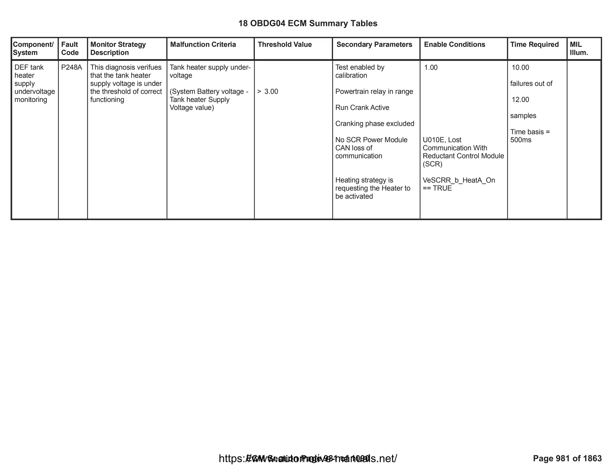

![Component/
System
Fault
Code
Monitor Strategy
Description
Malfunction Criteria Threshold Value Secondary Parameters Enable Conditions Time Required MIL
Illum.
Closed Loop
Reductant
Injection
Control At
Limit - Flow
Too Low
P249D This diagnosis checks
if the DEF injection
system has exceeded
the limit of correction
authority.
The monitoring is
executed by comparing
the long-term
adaptation factor
(LTAF) with a
calibratable threshold:
LTAF > OBD high
threshold.
The long-term
adaptation factor is
calculated based on
the information given
by the NH3 storage
correction strategy.
This factor represents
the measured deviation
of the complete SCR
system and shall be
used to compensate it
by making a correction
over the DEF injection
quantity.
Long-term adaptation
factor (LTAF) higher than
calibratable threshold
LTAF > 1.99 Test enabled by
calibration;
CalOut = [Boolean];
1 One failure to set
the DTC.
Type B,
2 Trips
18 OBDG04 ECM Summary Tables
ECM Section Page 983 of 1090 Page 983 of 1863
https://www.automotive-manuals.net/](https://image.slidesharecdn.com/gmcenginefaultcodesdtc1-230327071418-56d3c5bb/75/18-OBDG04-ECM-Summary-Tables-983-2048.jpg)
![Component/
System
Fault
Code
Monitor Strategy
Description
Malfunction Criteria Threshold Value Secondary Parameters Enable Conditions Time Required MIL
Illum.
Closed Loop
Reductant
Injection
Control At
Limit - Flow
Too High
P249E This diagnosis checks
if the DEF injection
system has exceeded
the limit of correction
authority.
The monitoring is
executed by comparing
the long-term
adaptation factor
(LTAF) with a
calibratable threshold:
LTAF < OBD low
threshold.
The long-term
adaptation factor is
calculated based on
the information given
by the NH3 storage
correction strategy.
This factor represents
the measured deviation
of the complete SCR
system and shall be
used to compensate it
by making a correction
over the DEF injection
quantity.
Long-term adaptation
factor (LTAF) lower than
calibratable threshold
LTAF < 0.41 Test enabled by
calibration;
CalOut = [Boolean];
1 One failure to set
the DTC.
Type B,
2 Trips
18 OBDG04 ECM Summary Tables
ECM Section Page 984 of 1090 Page 984 of 1863
https://www.automotive-manuals.net/](https://image.slidesharecdn.com/gmcenginefaultcodesdtc1-230327071418-56d3c5bb/75/18-OBDG04-ECM-Summary-Tables-984-2048.jpg)
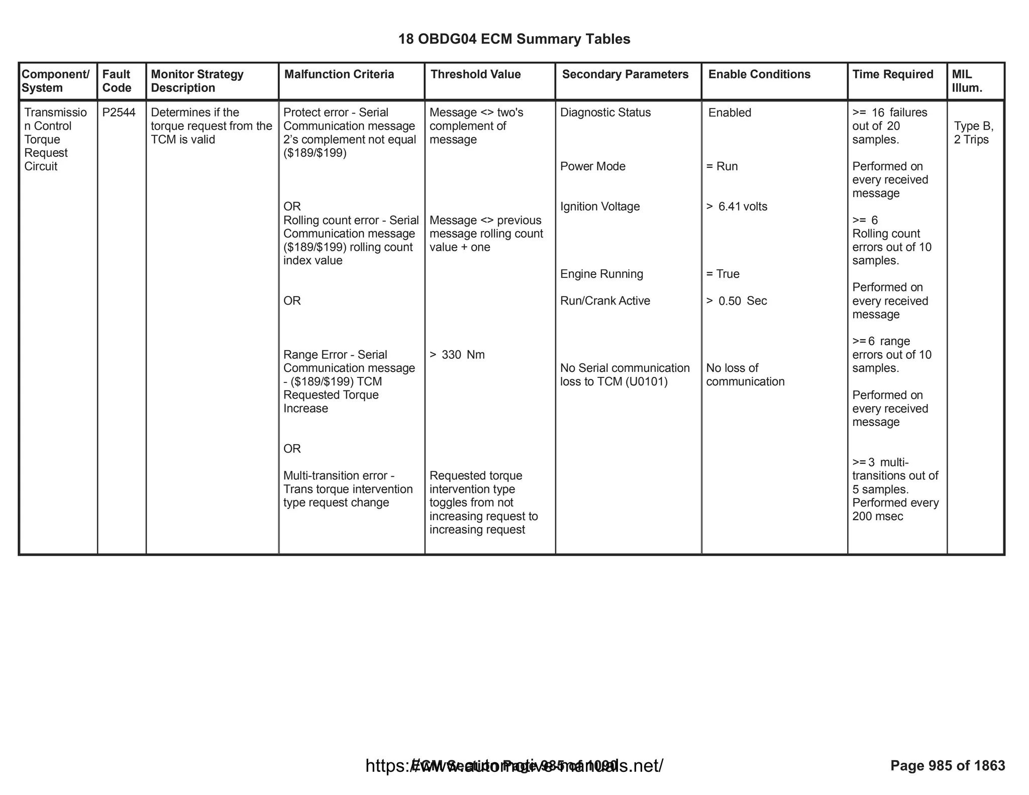
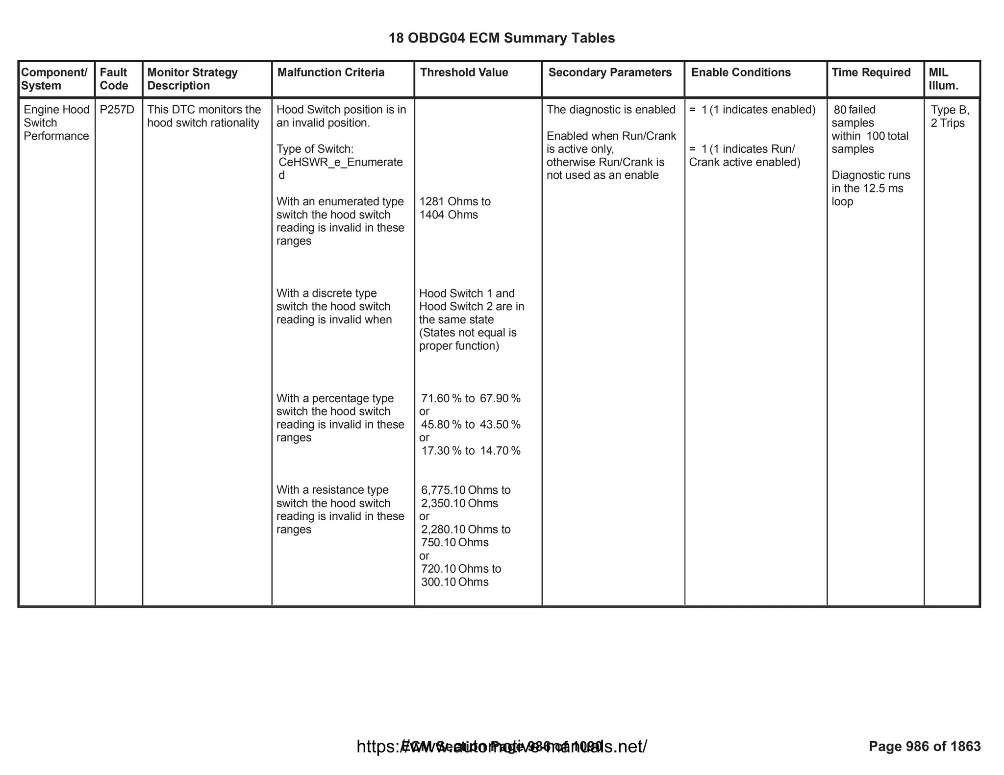

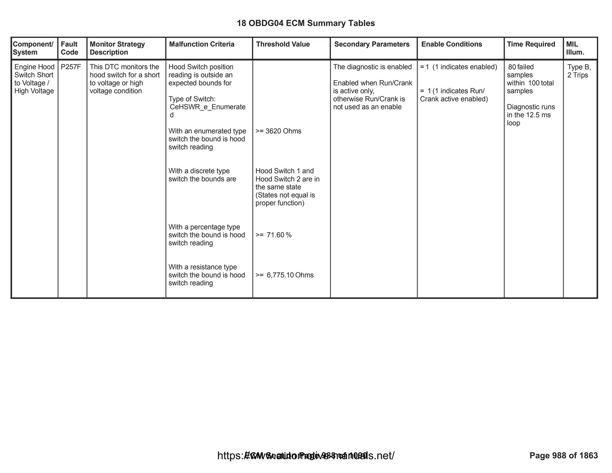
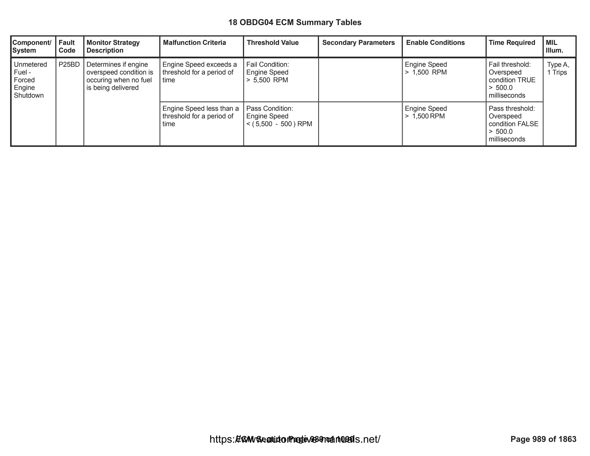

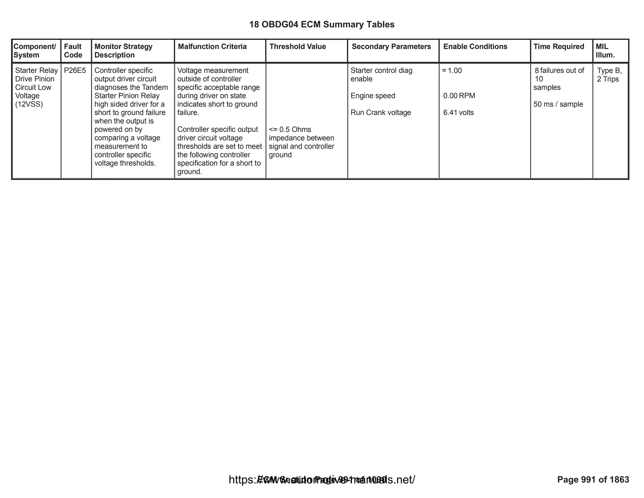
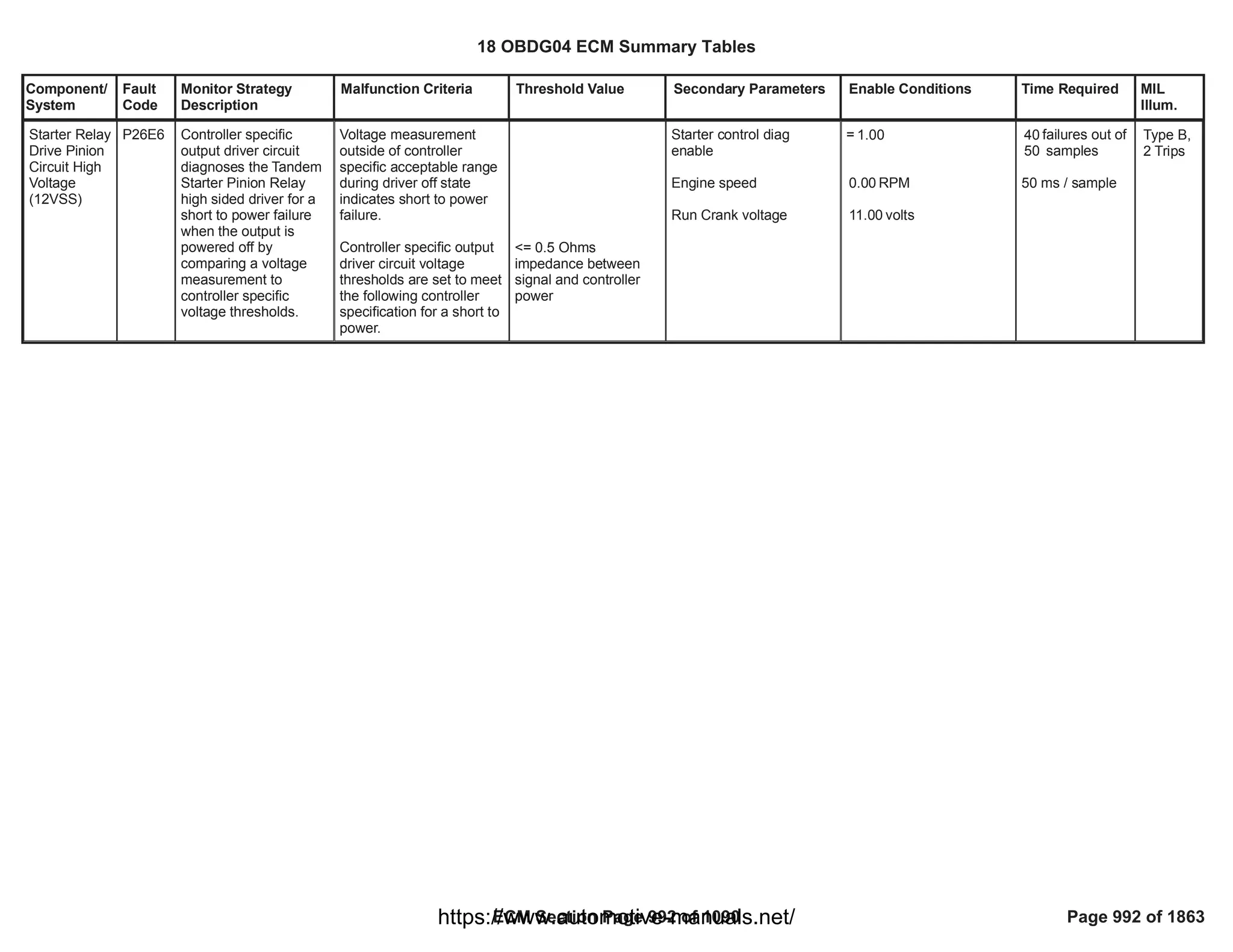
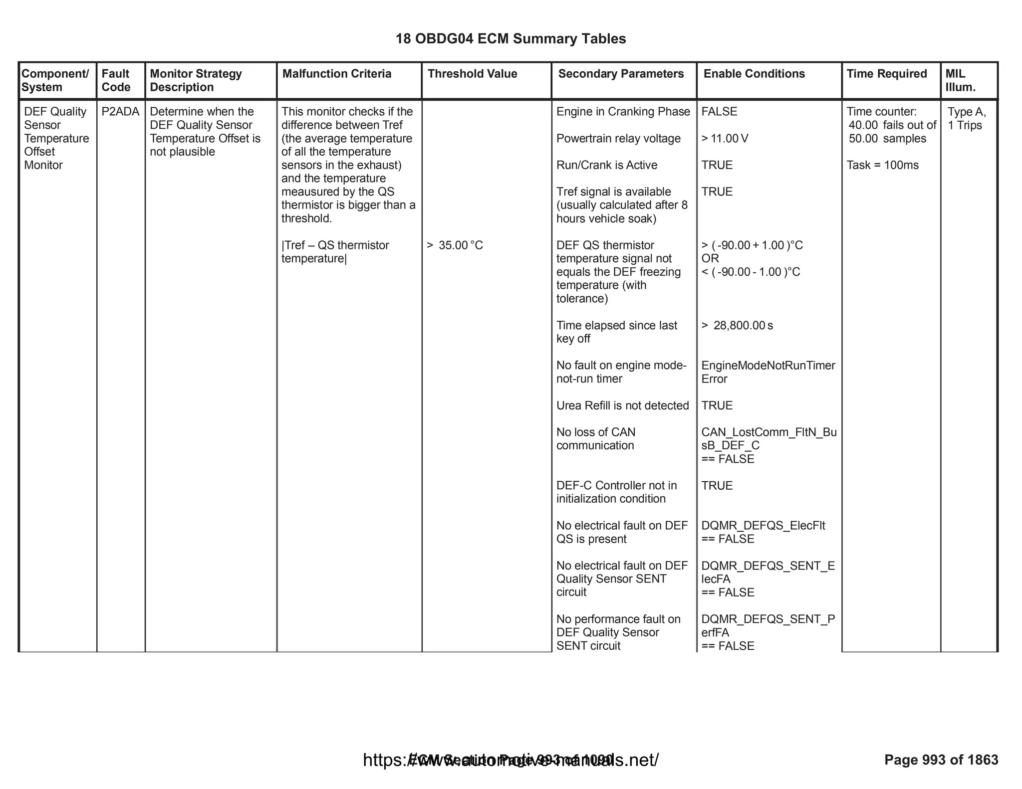
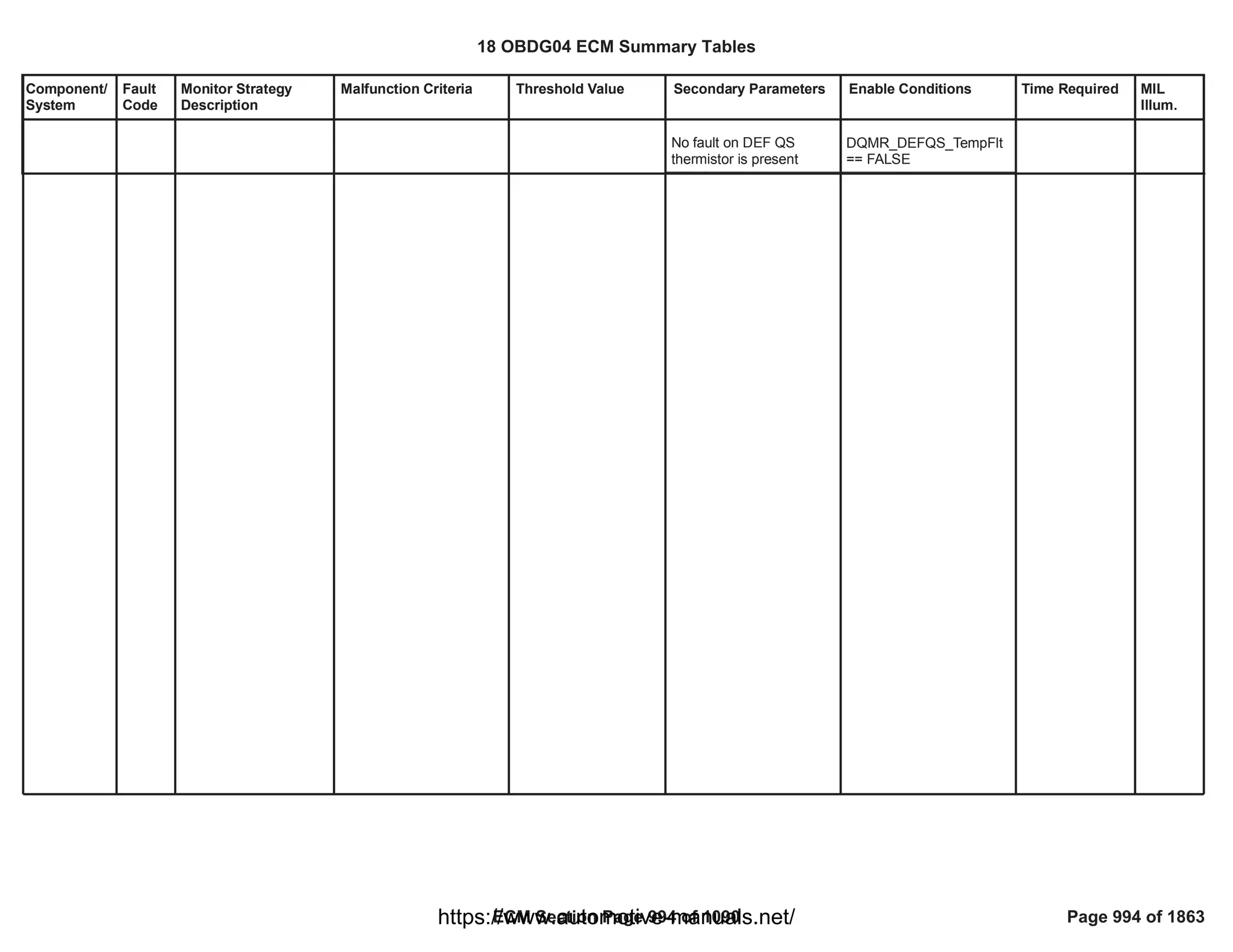
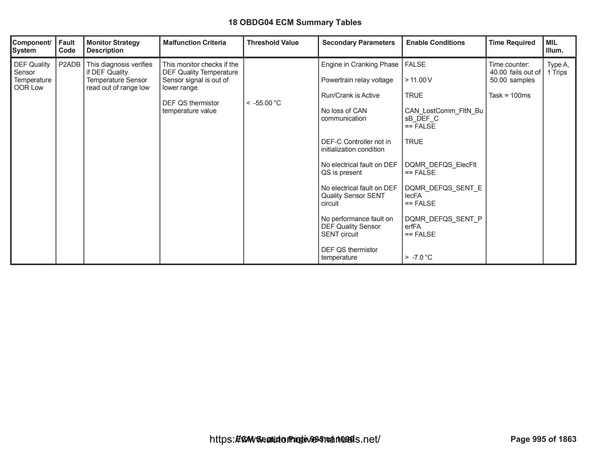

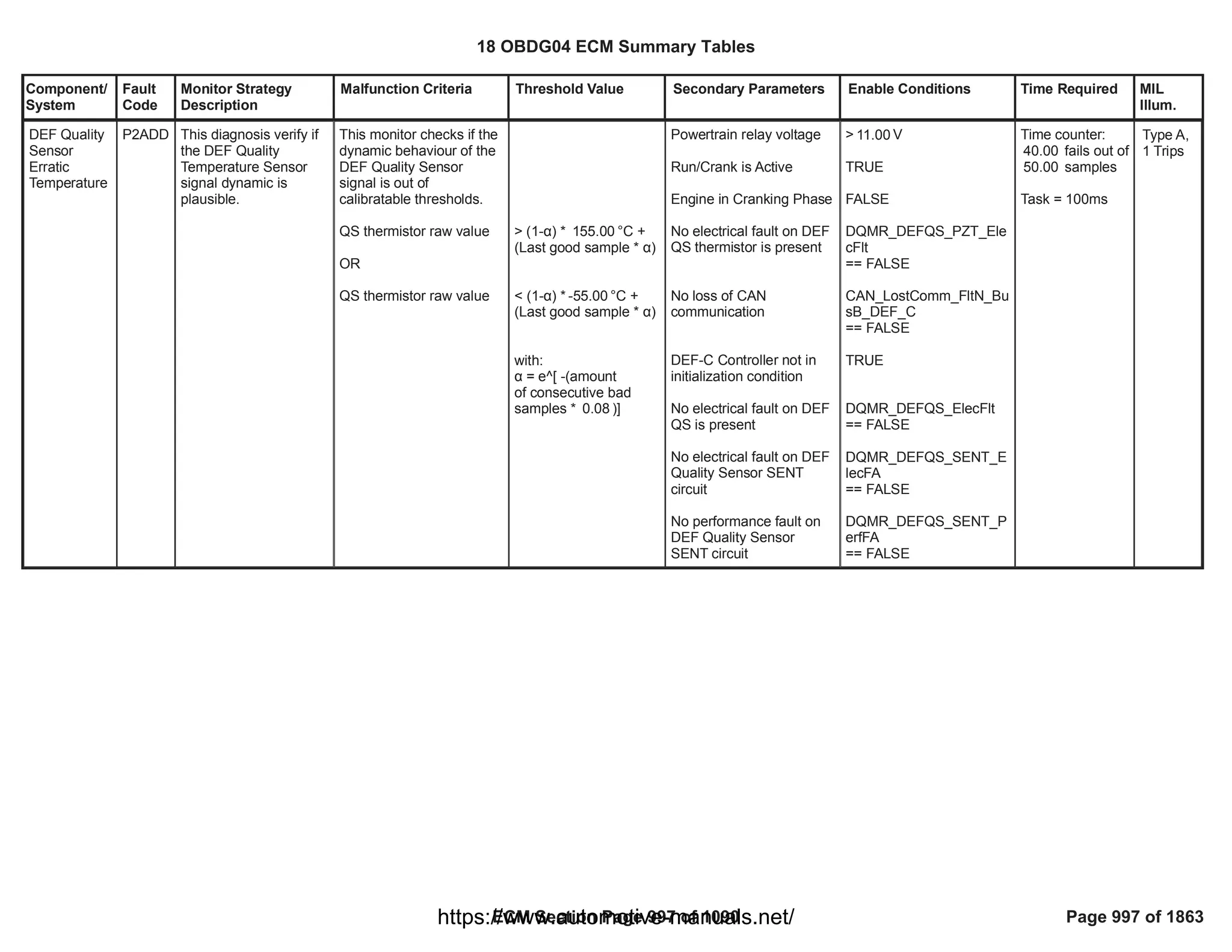
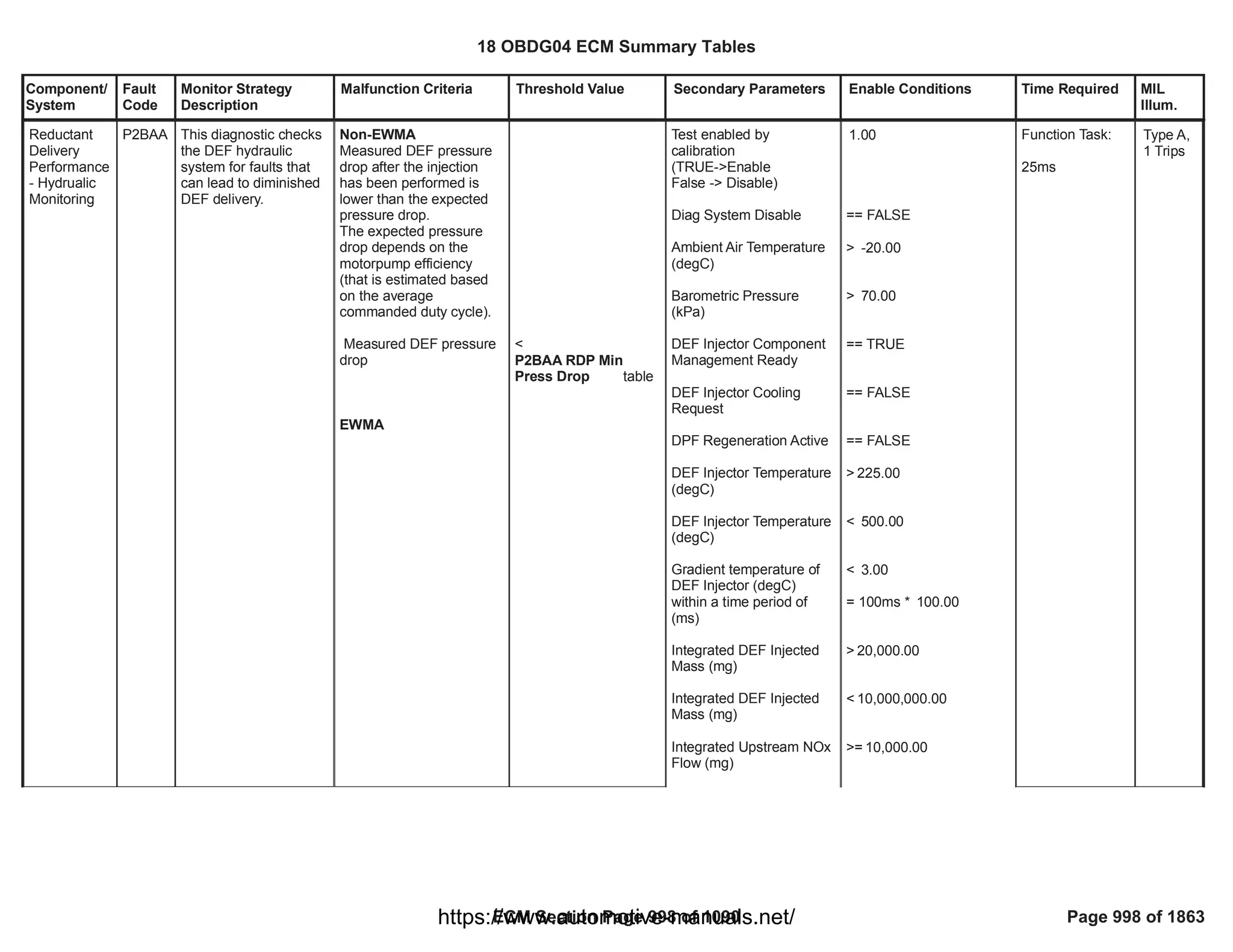
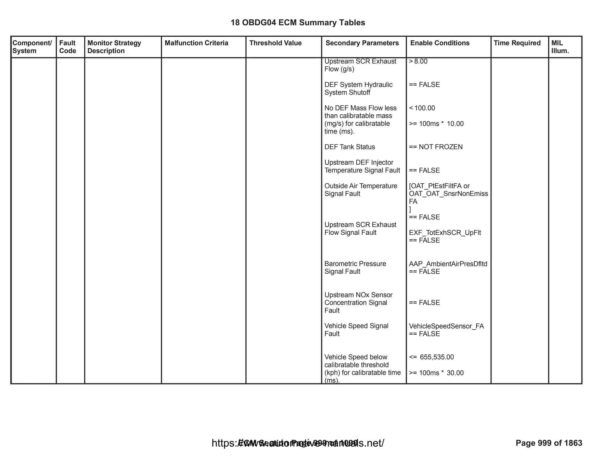
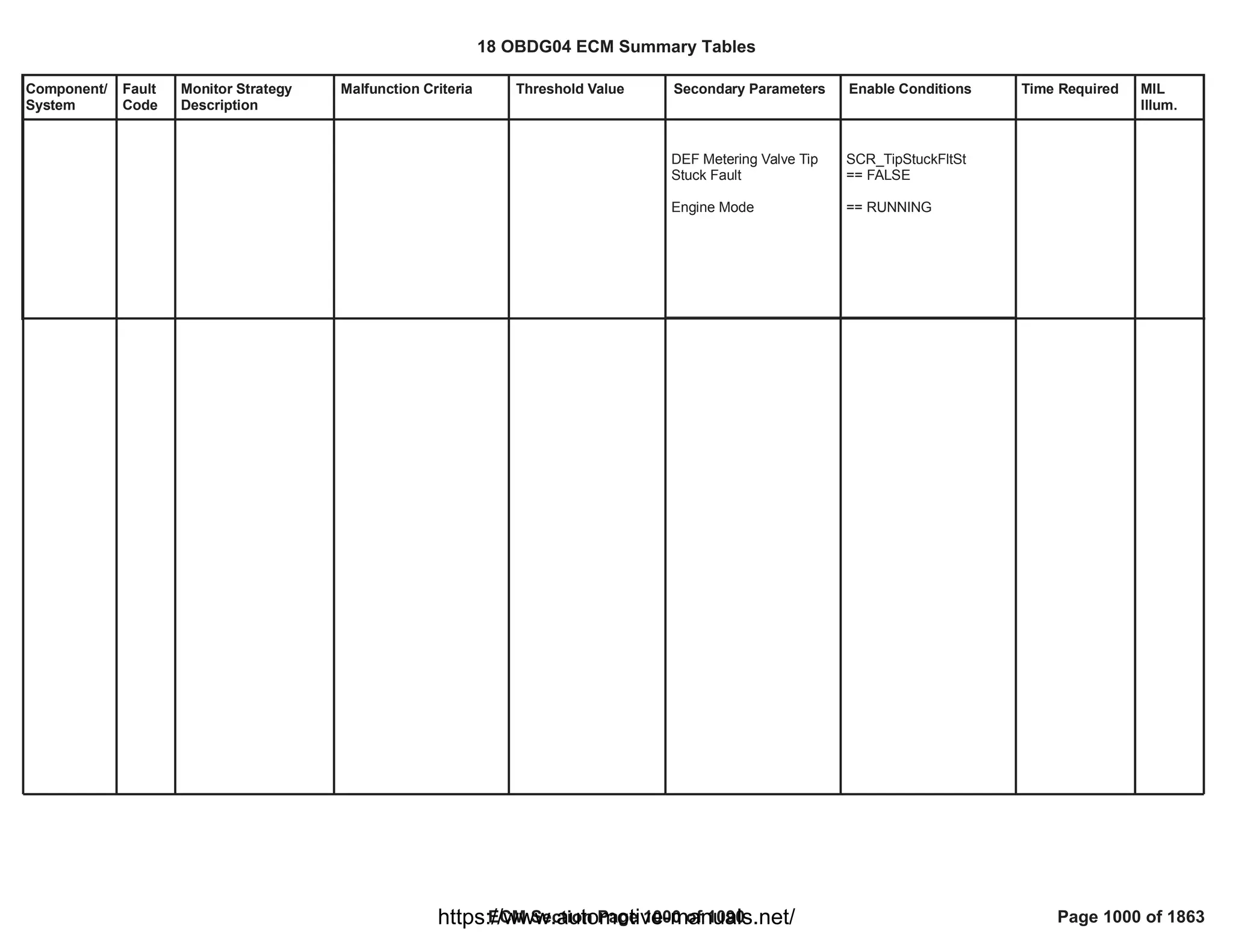

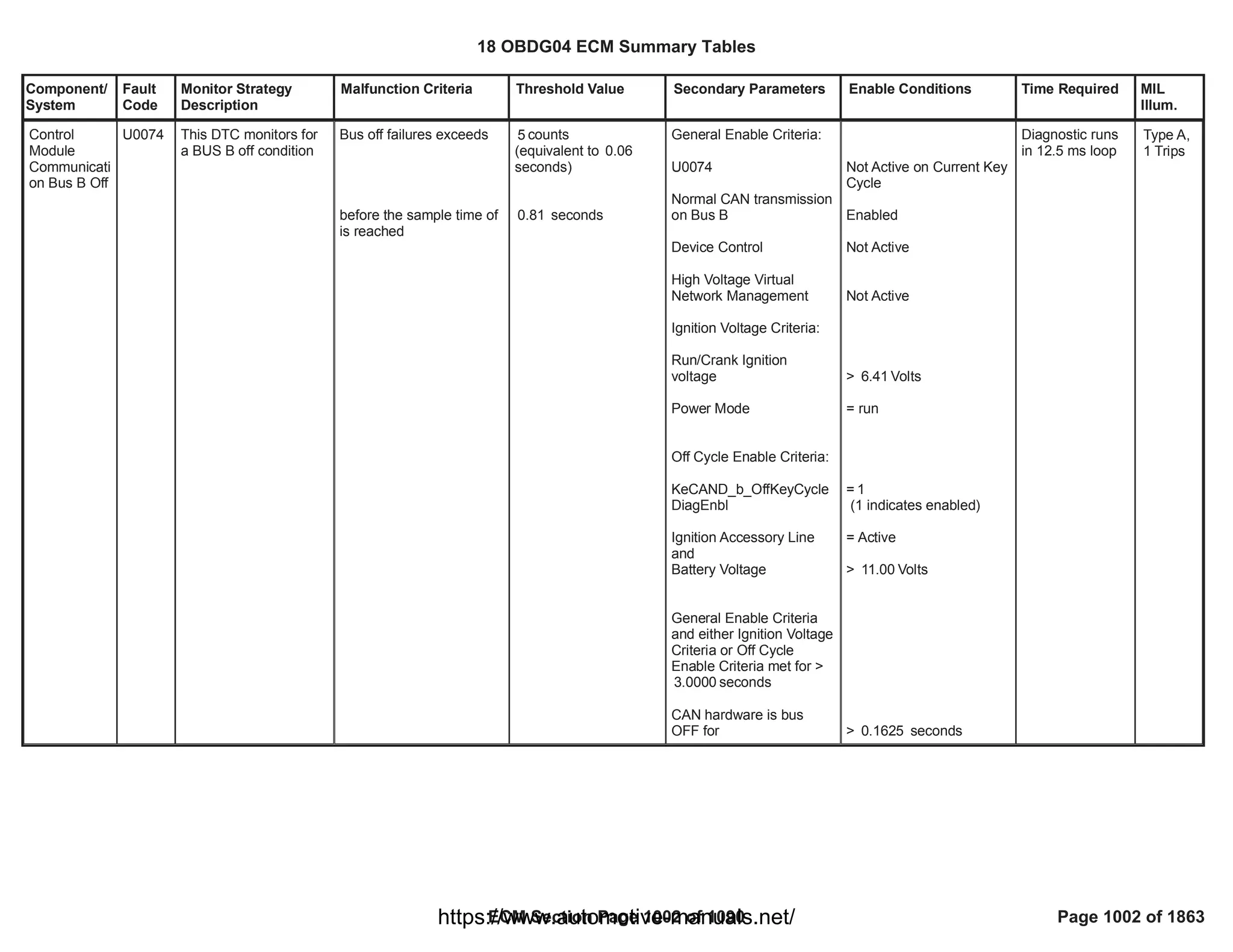
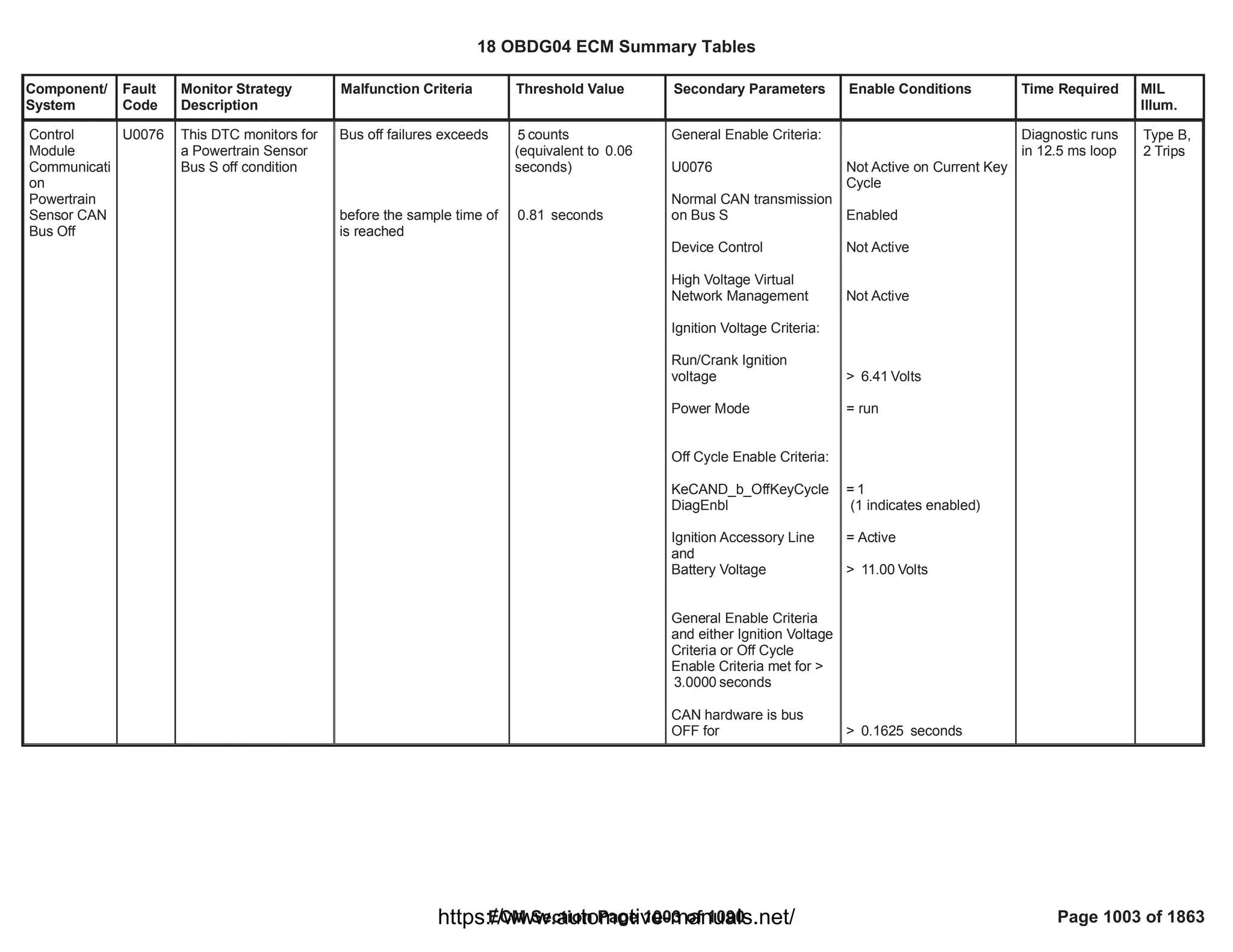
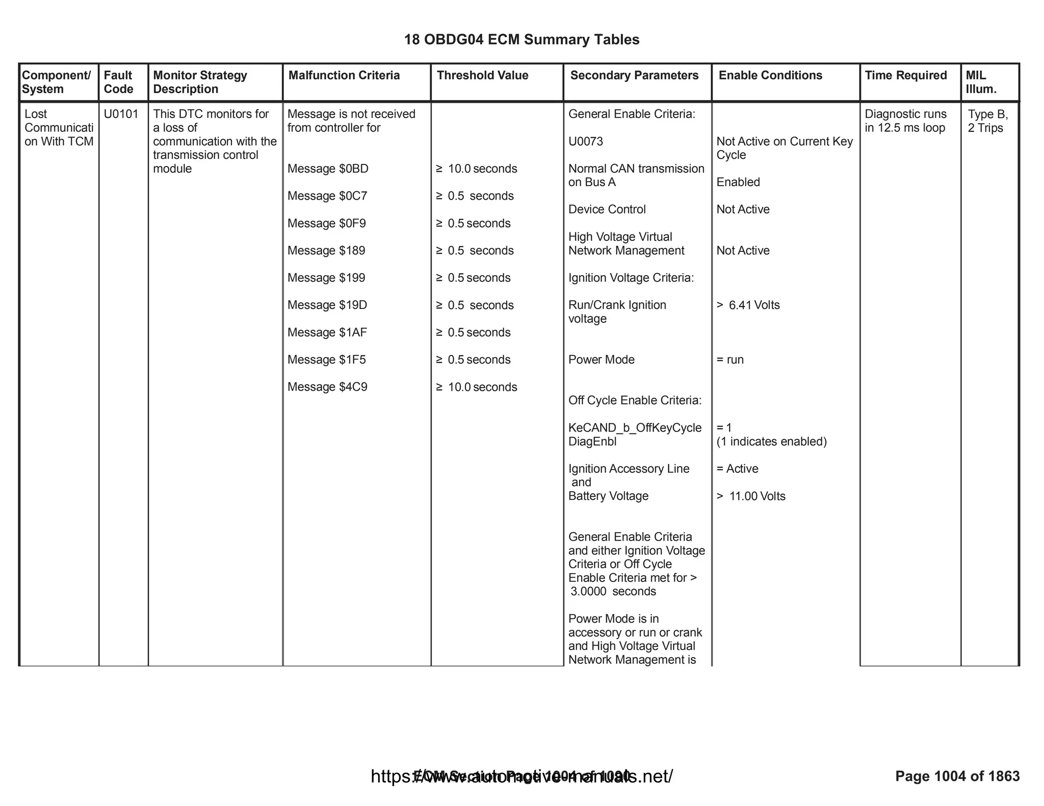
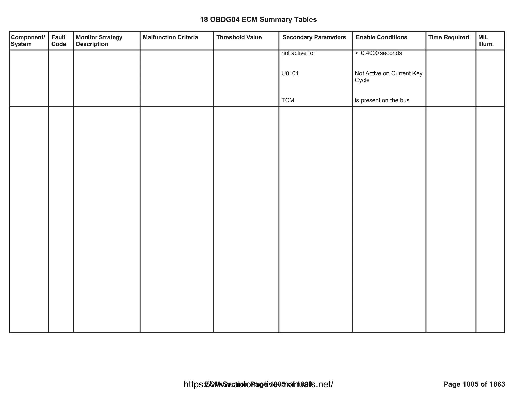
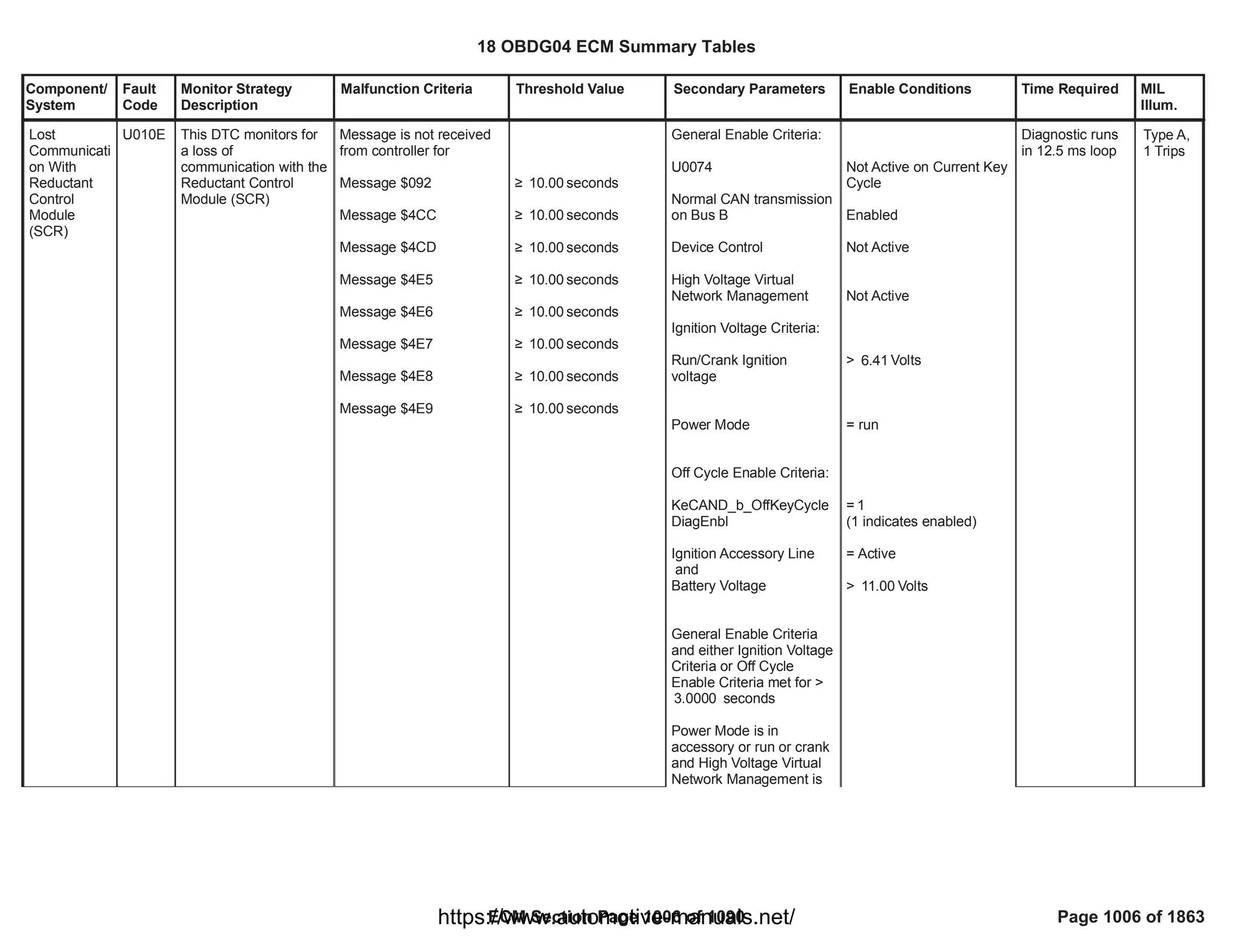
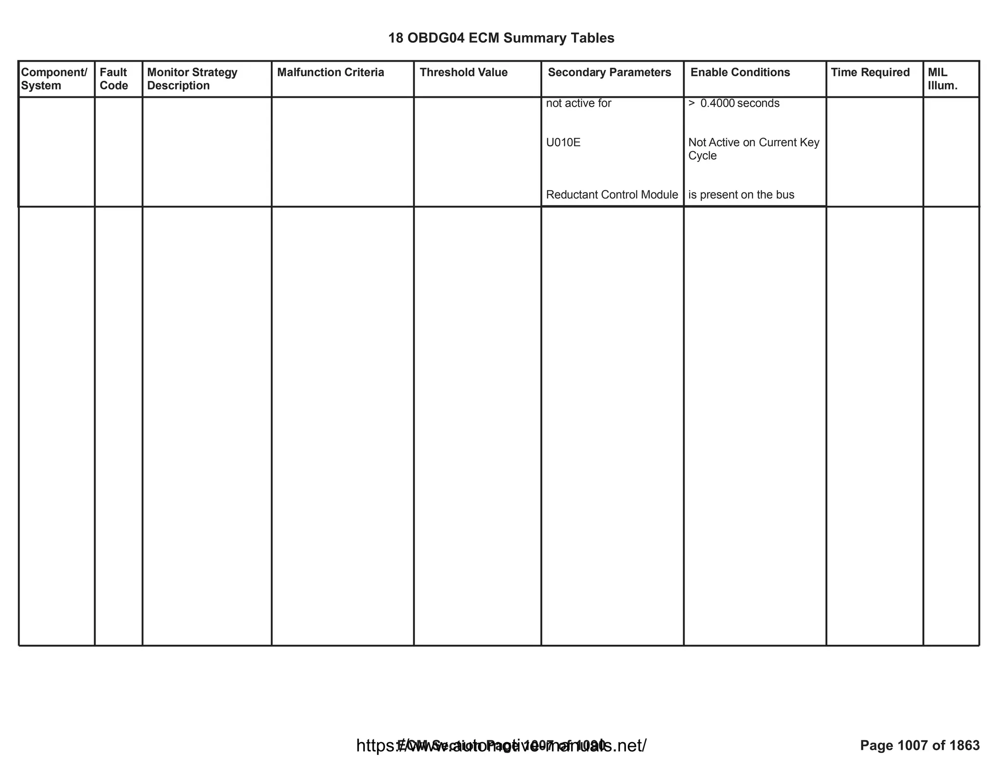
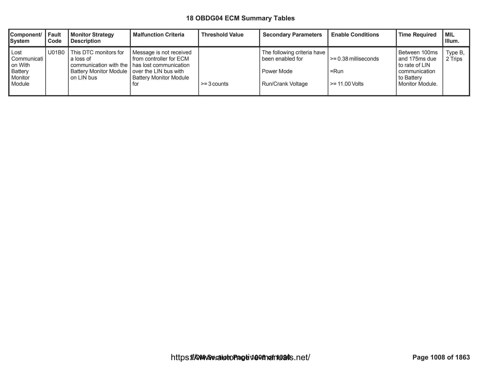
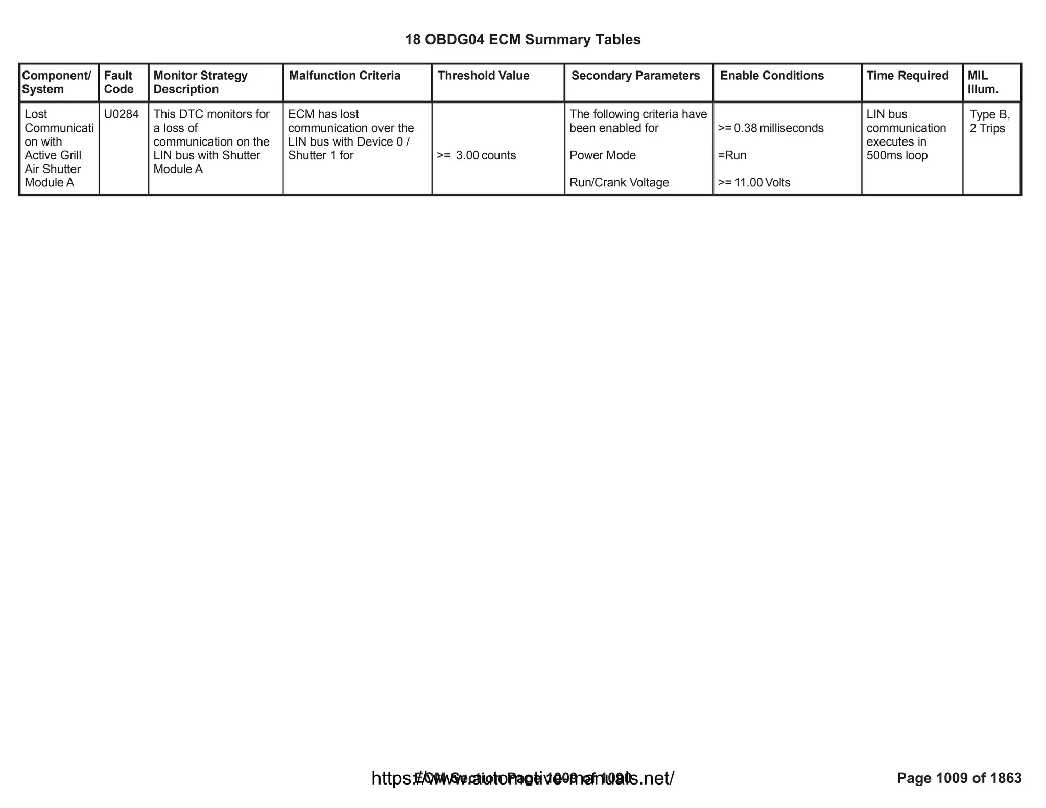
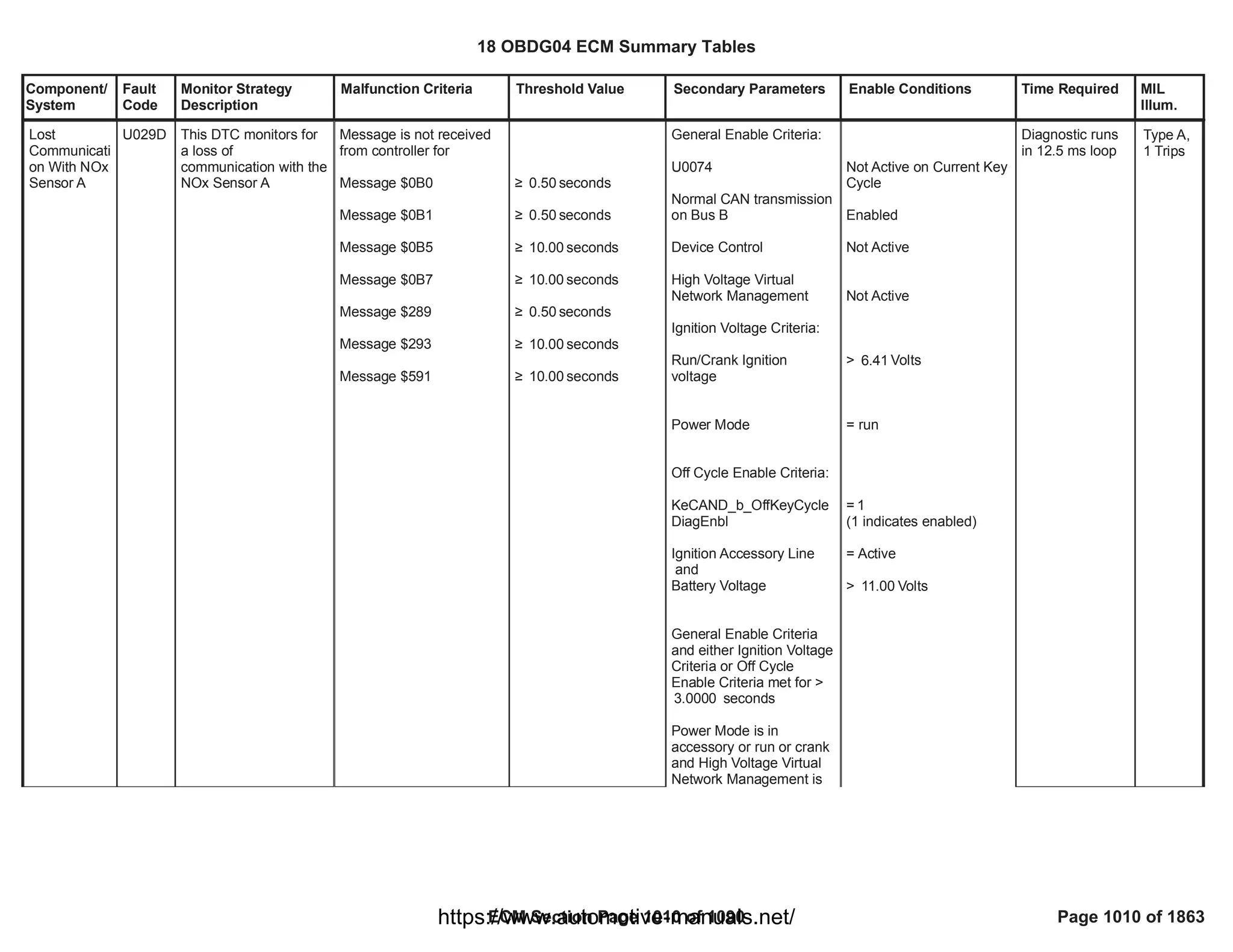
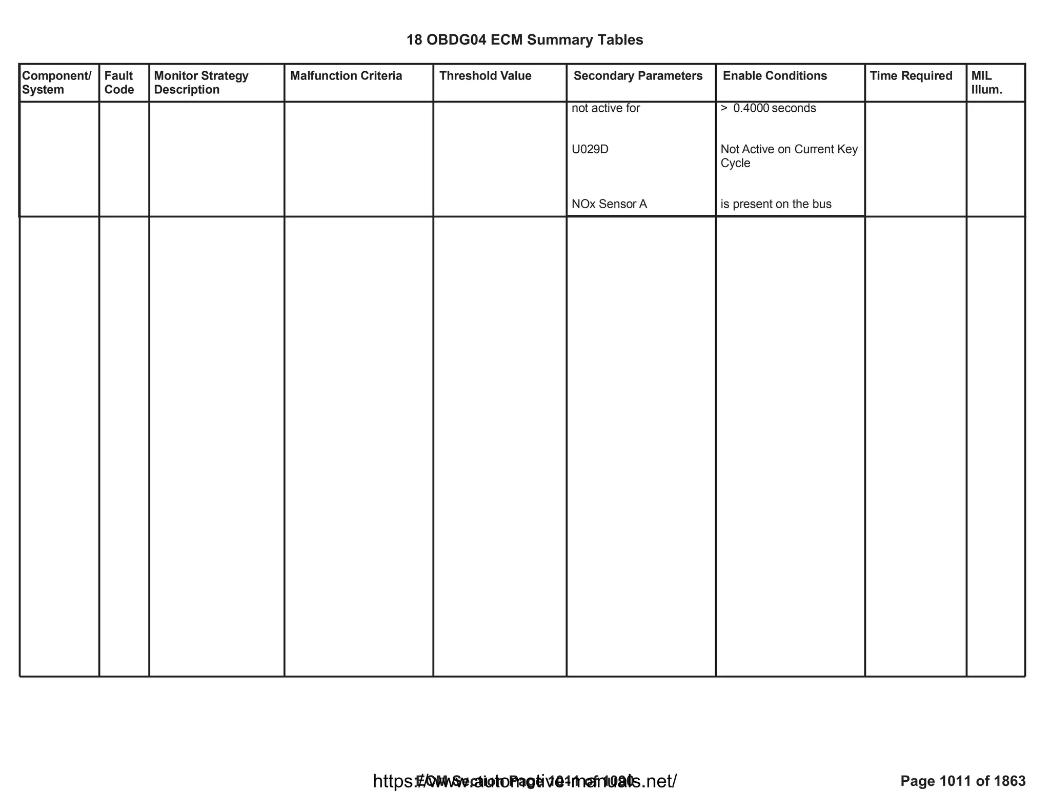
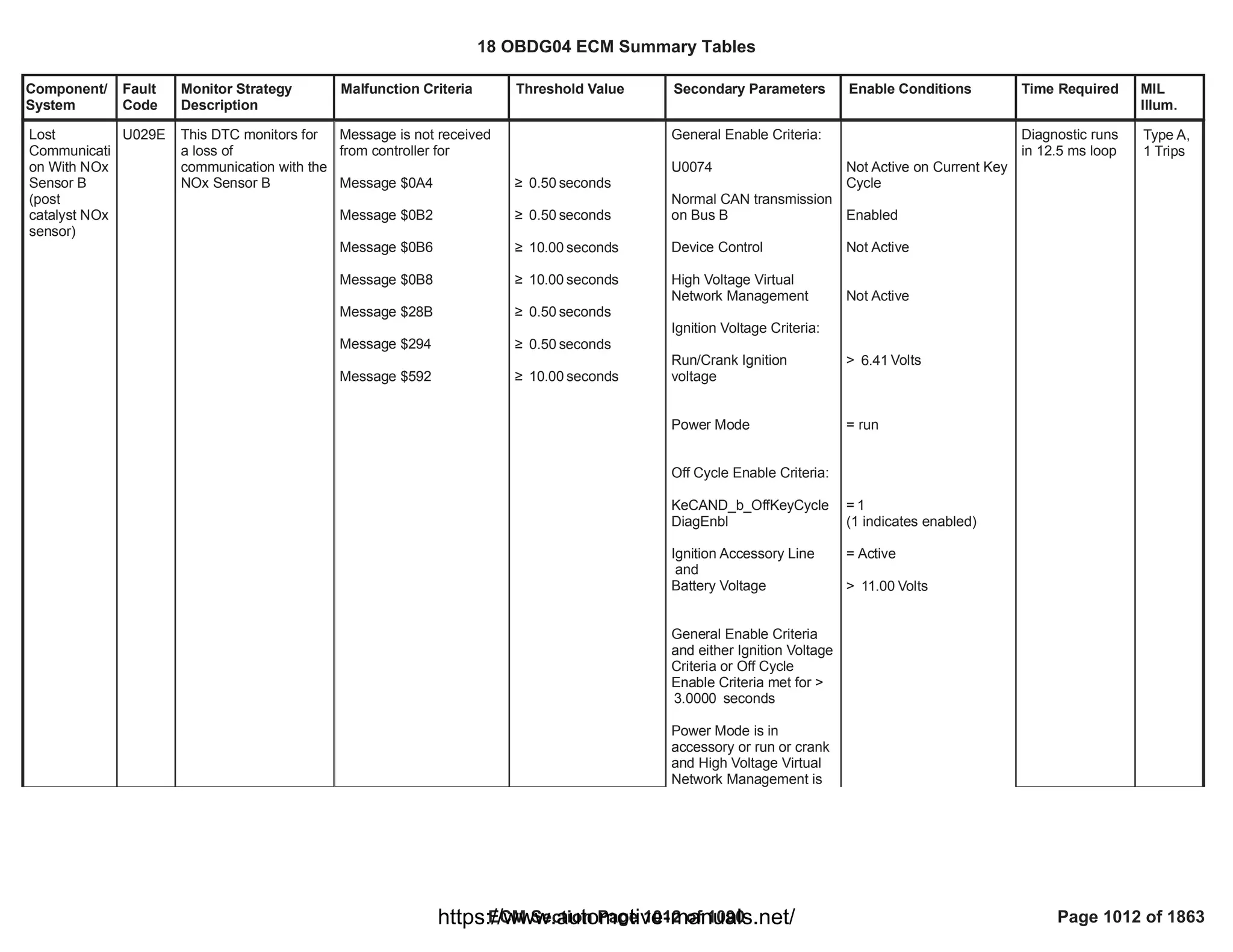
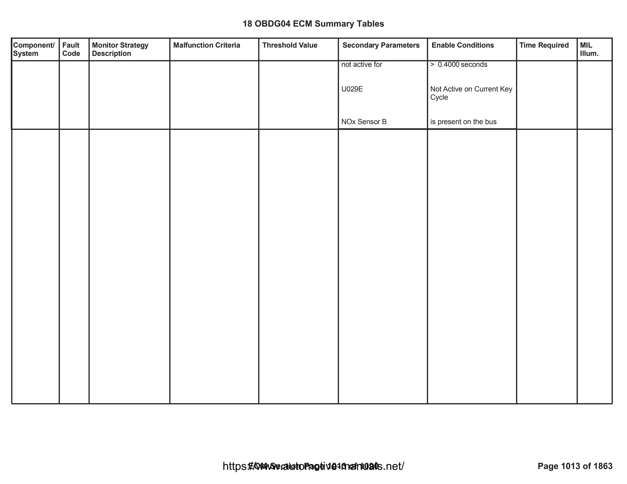
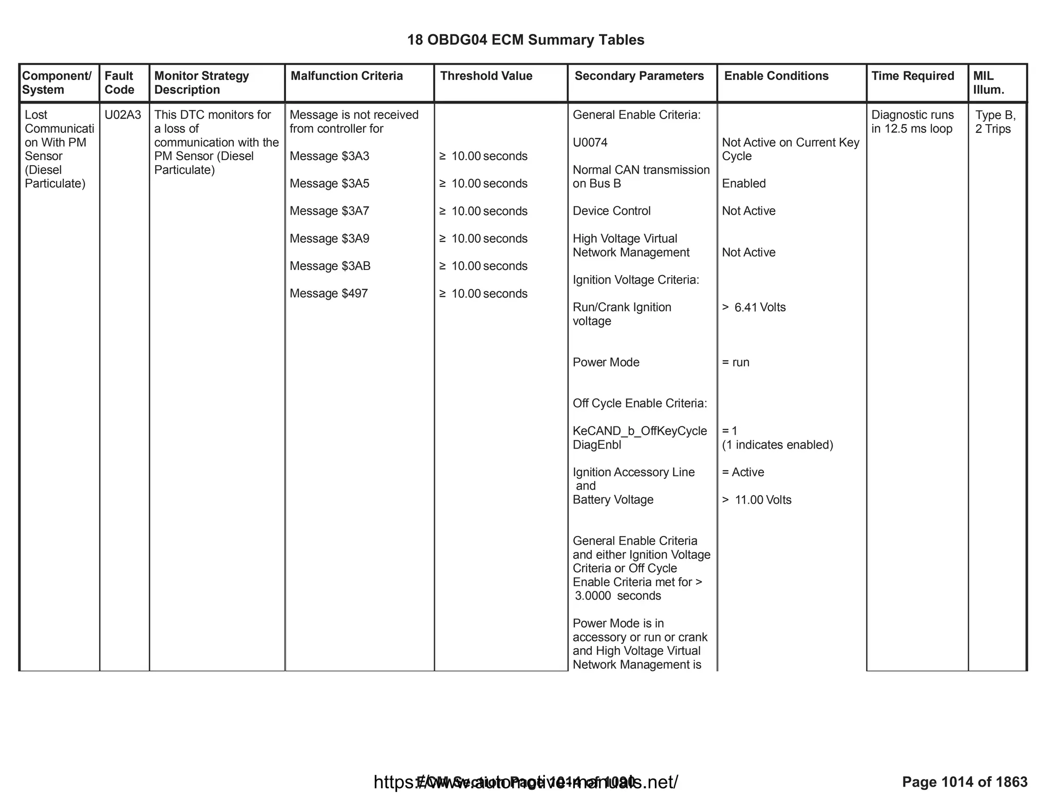
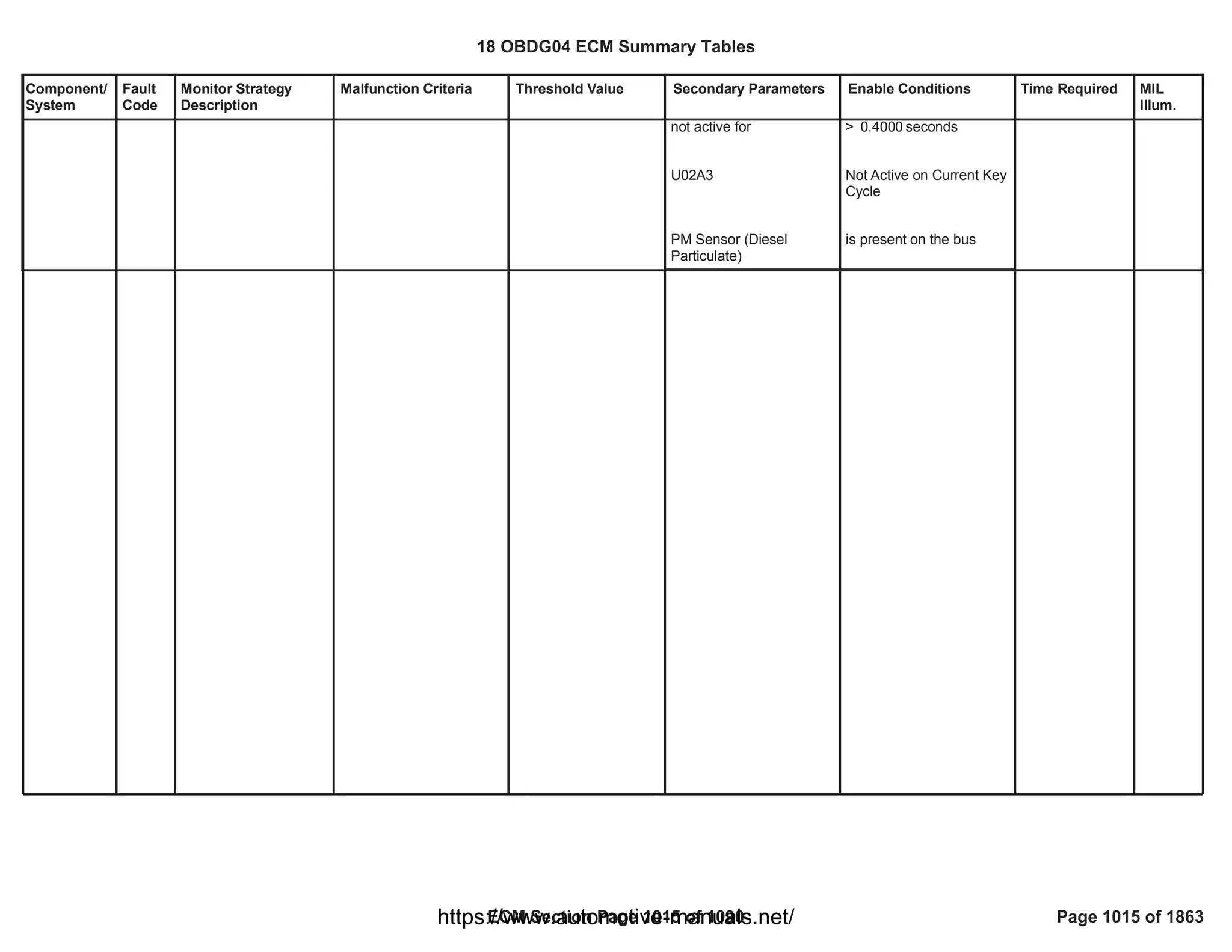
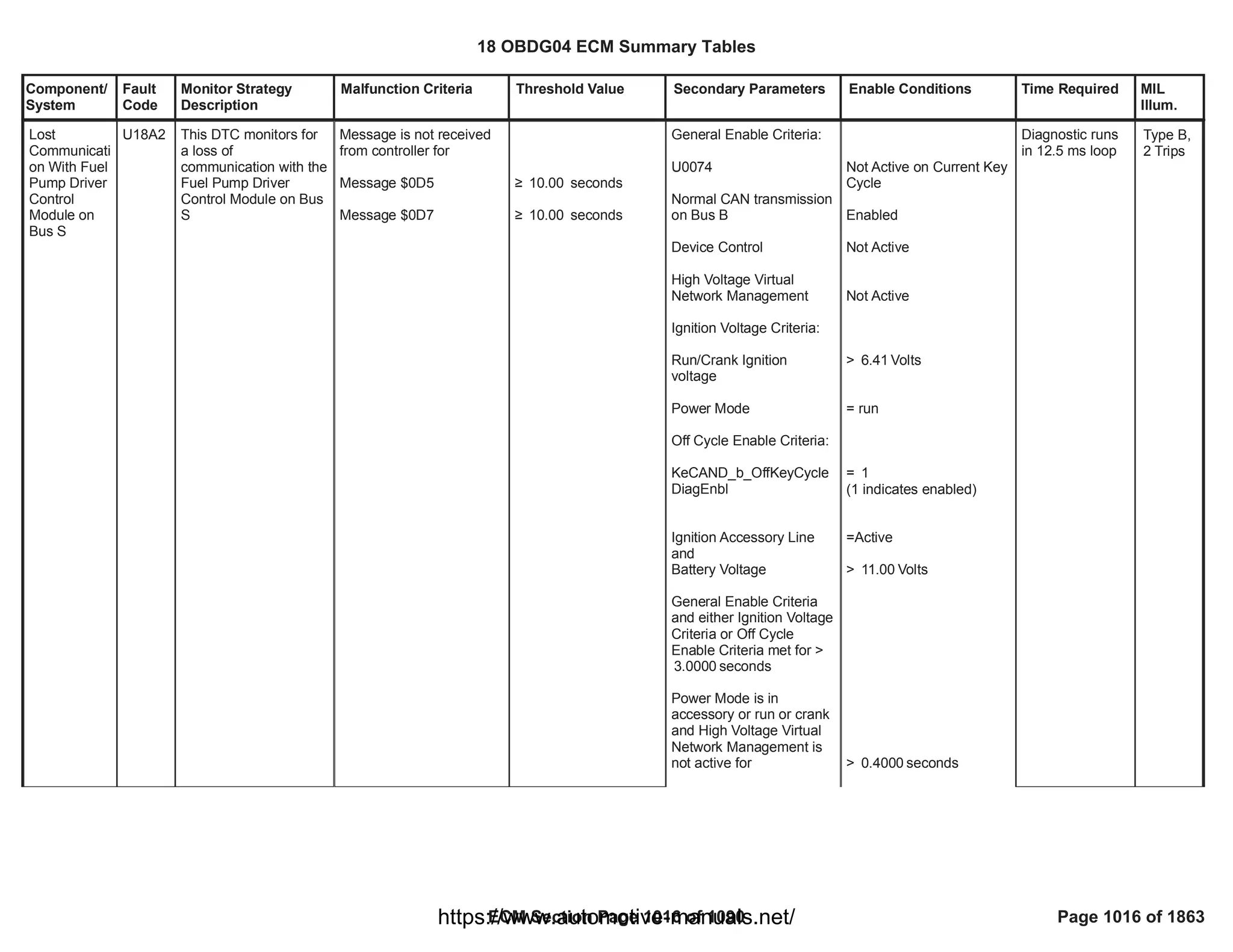

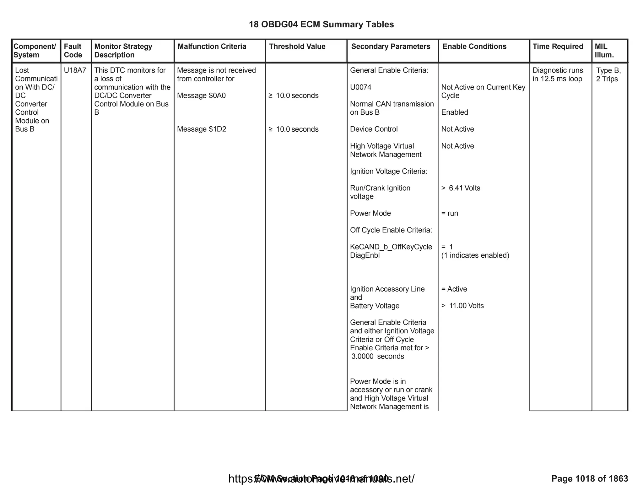
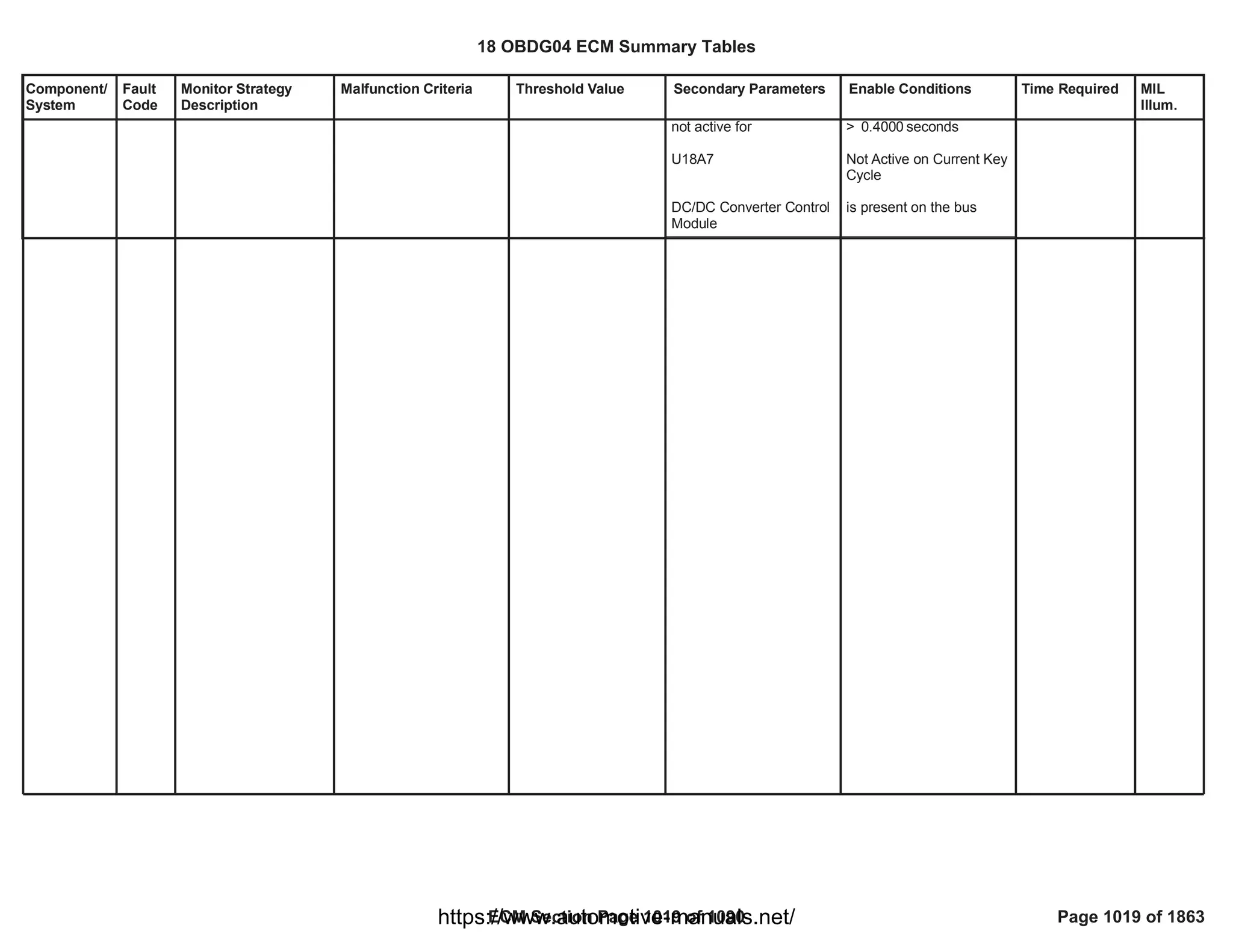
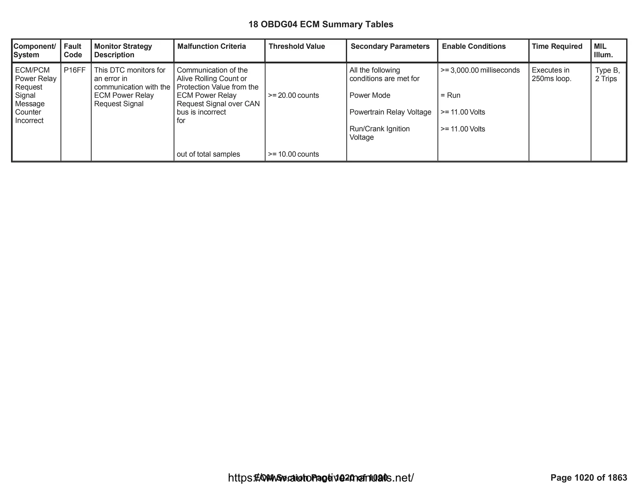
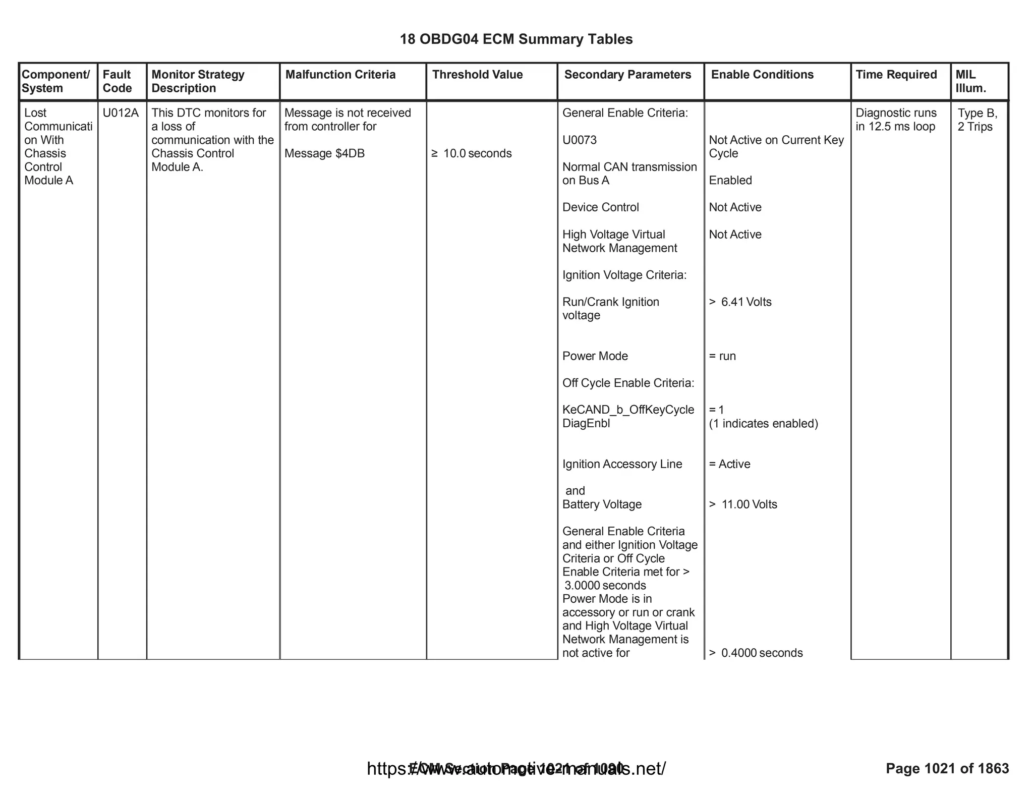
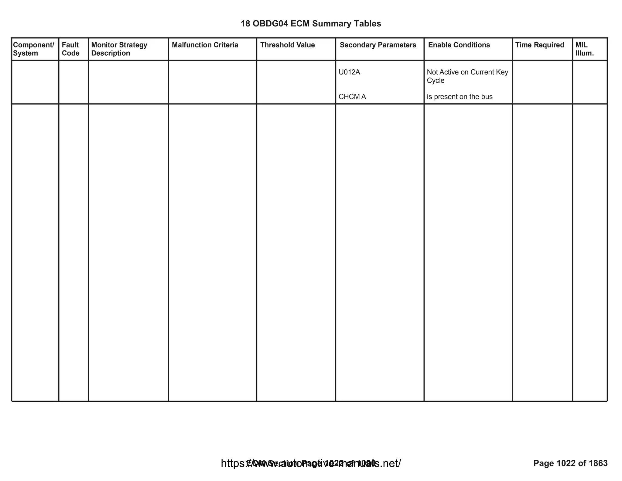
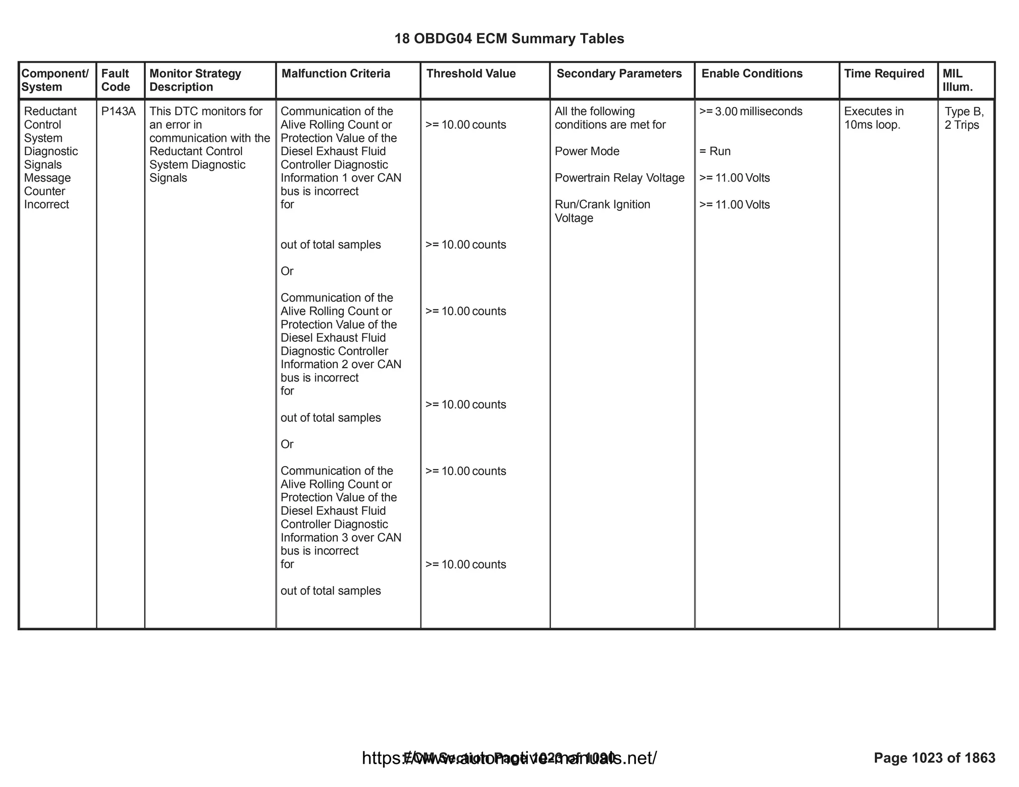
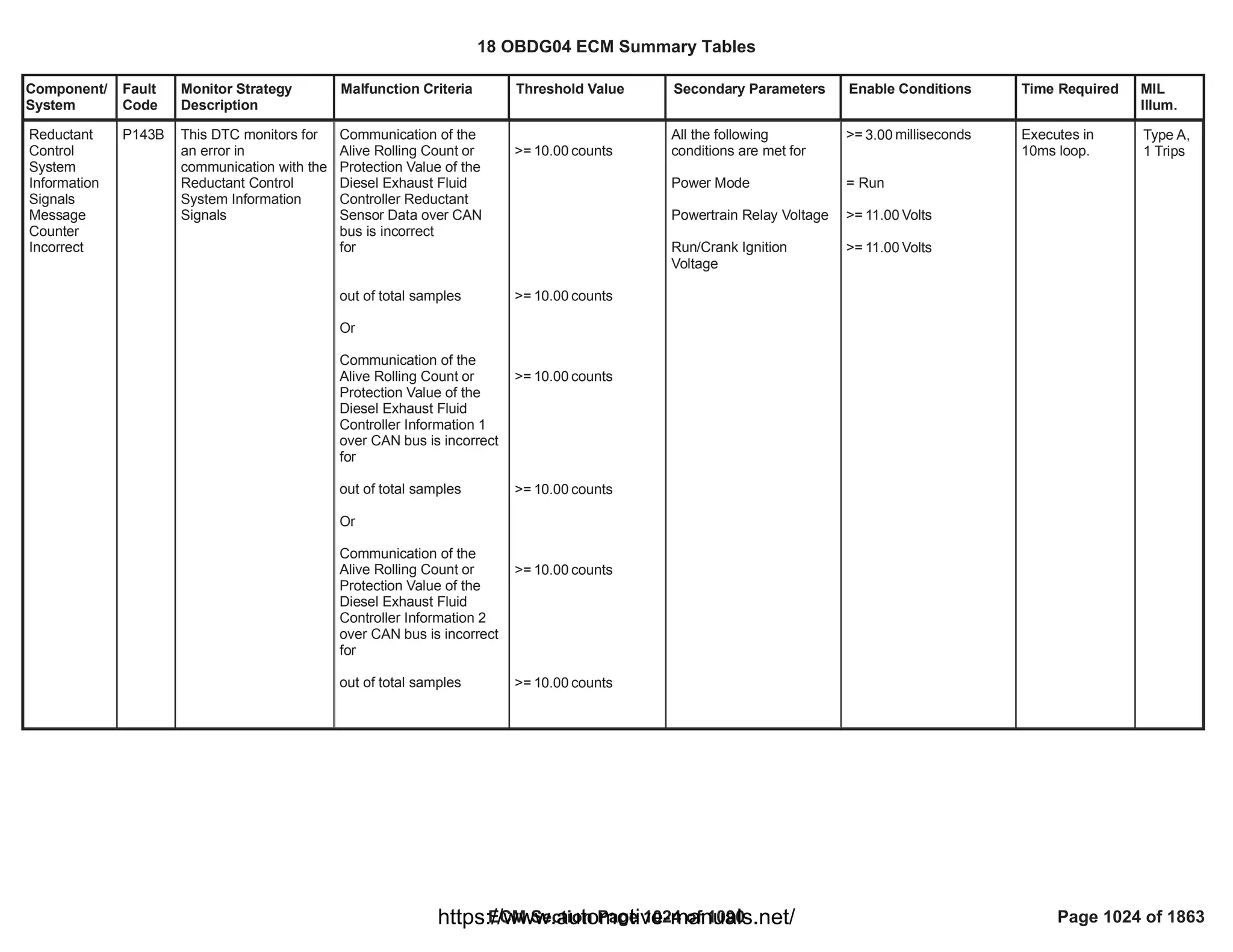
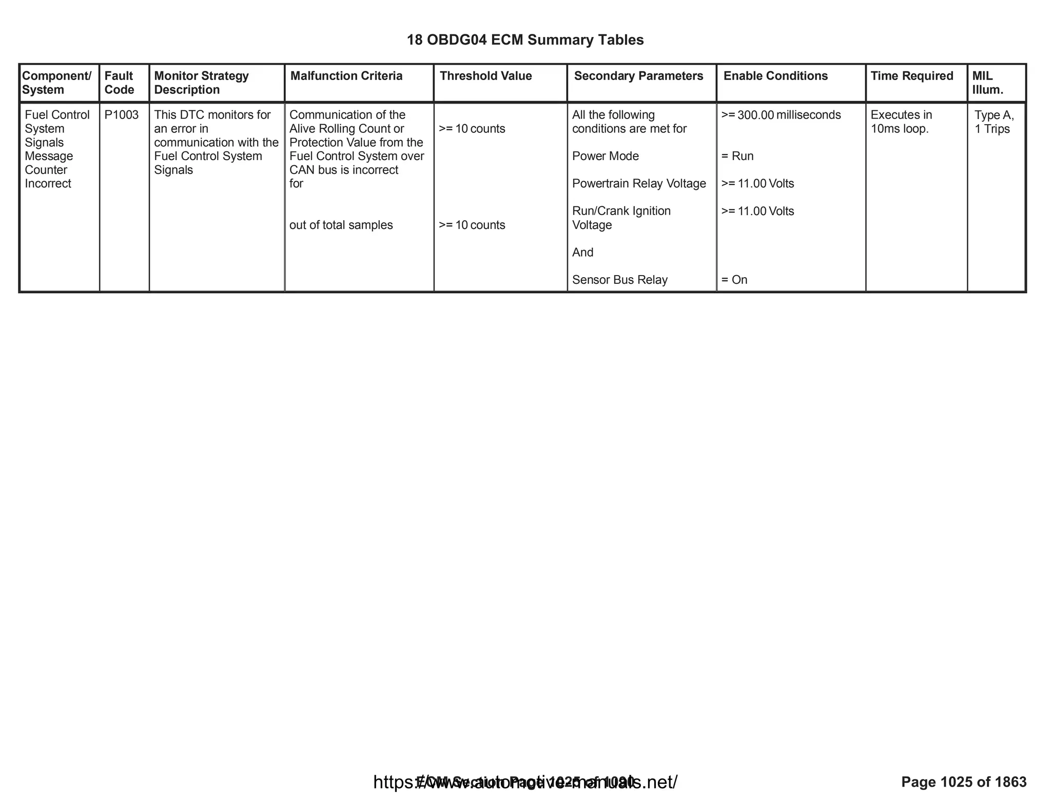
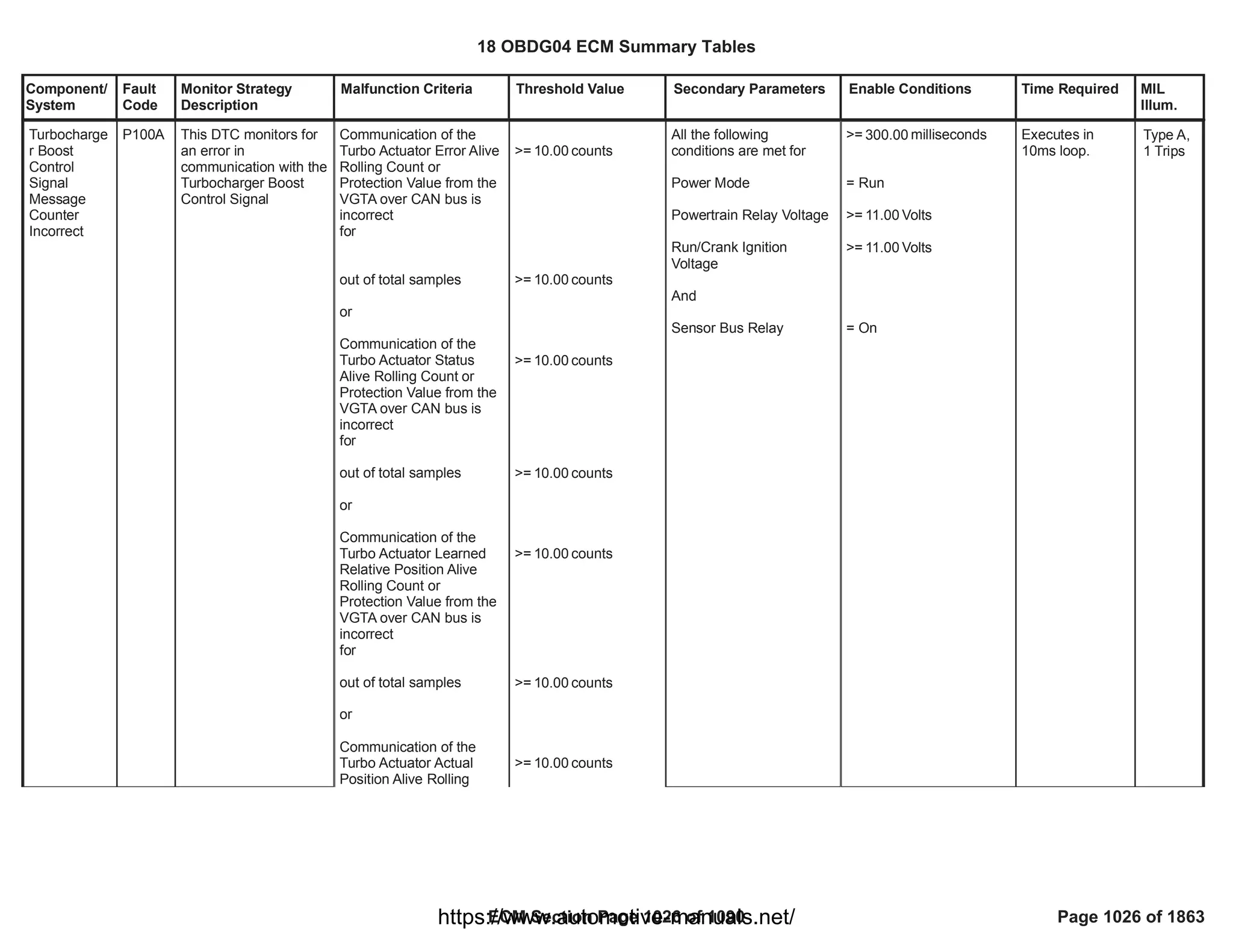
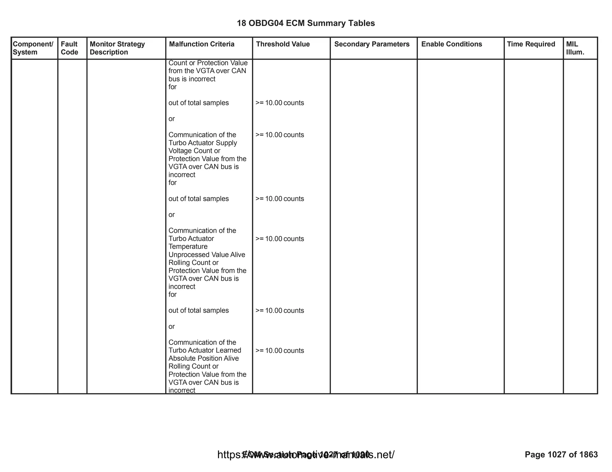
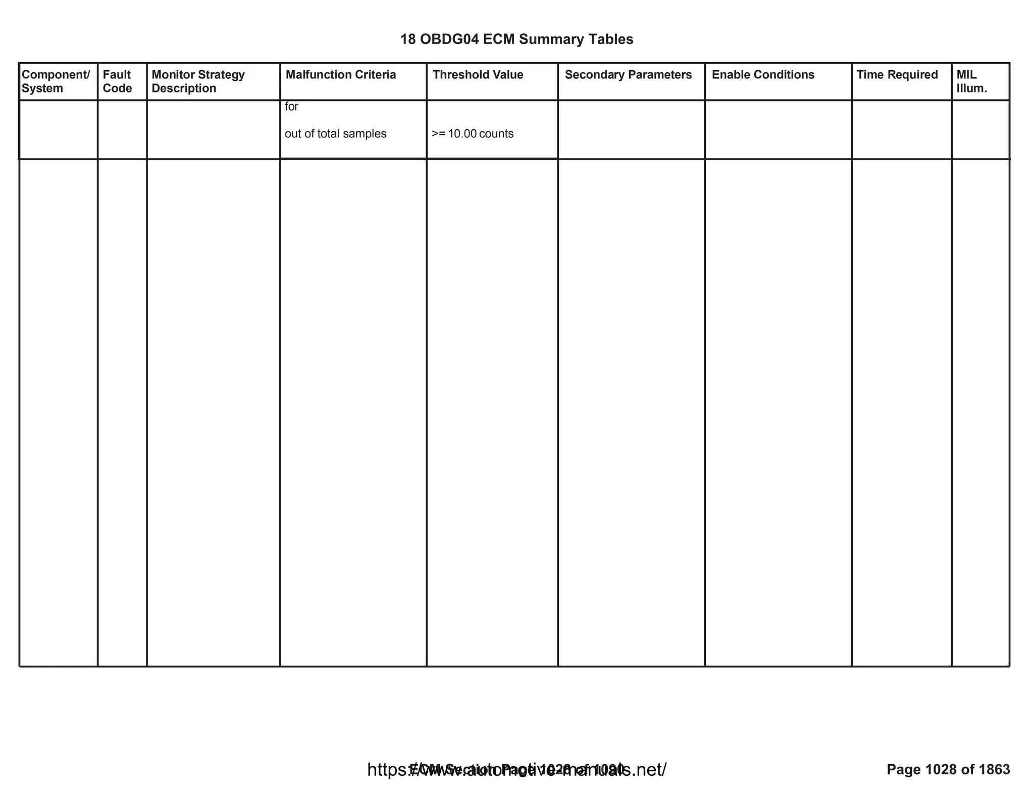
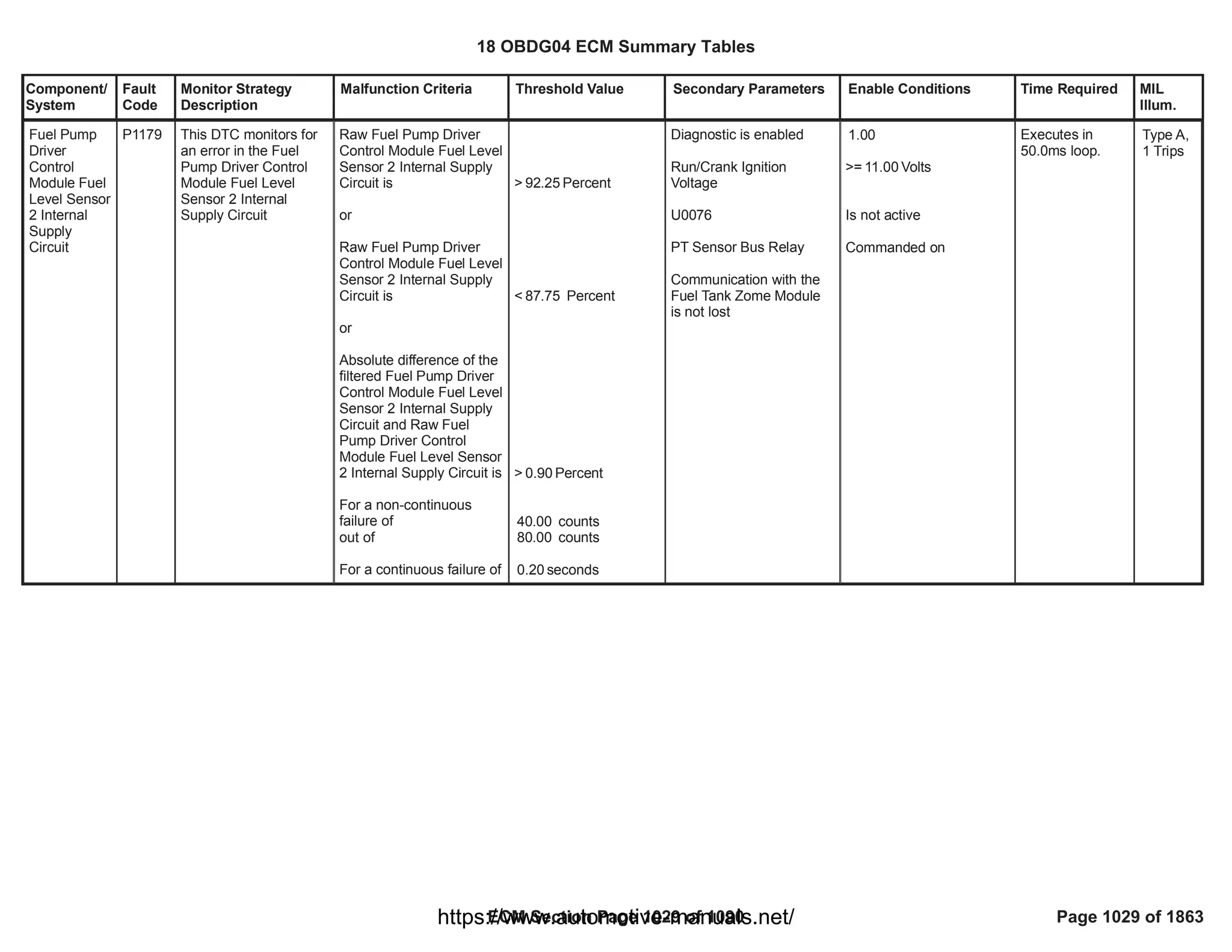
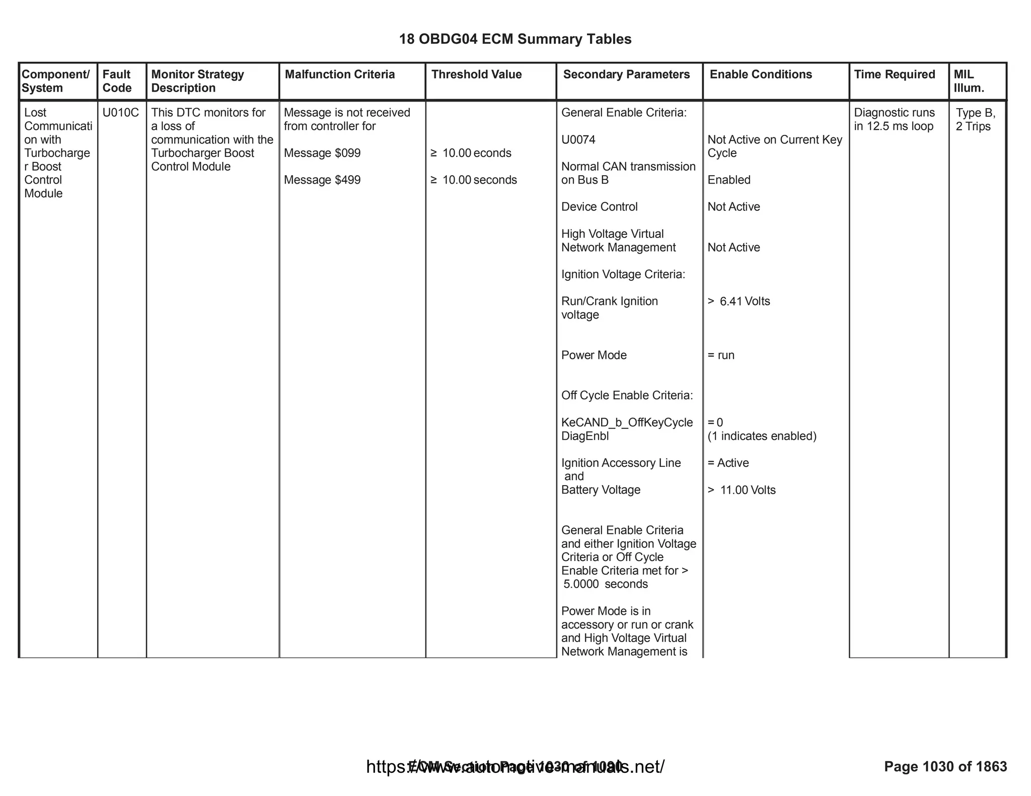
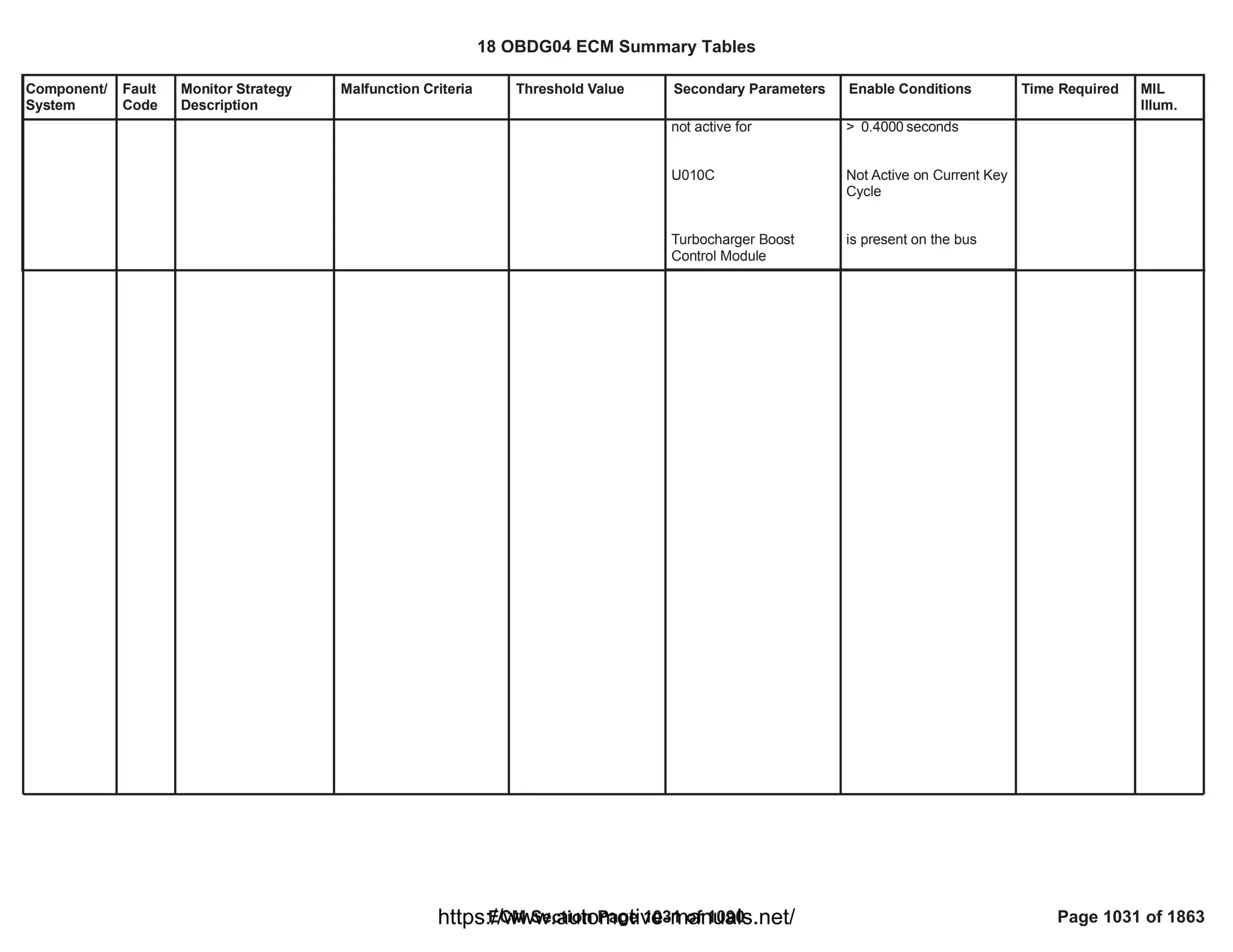
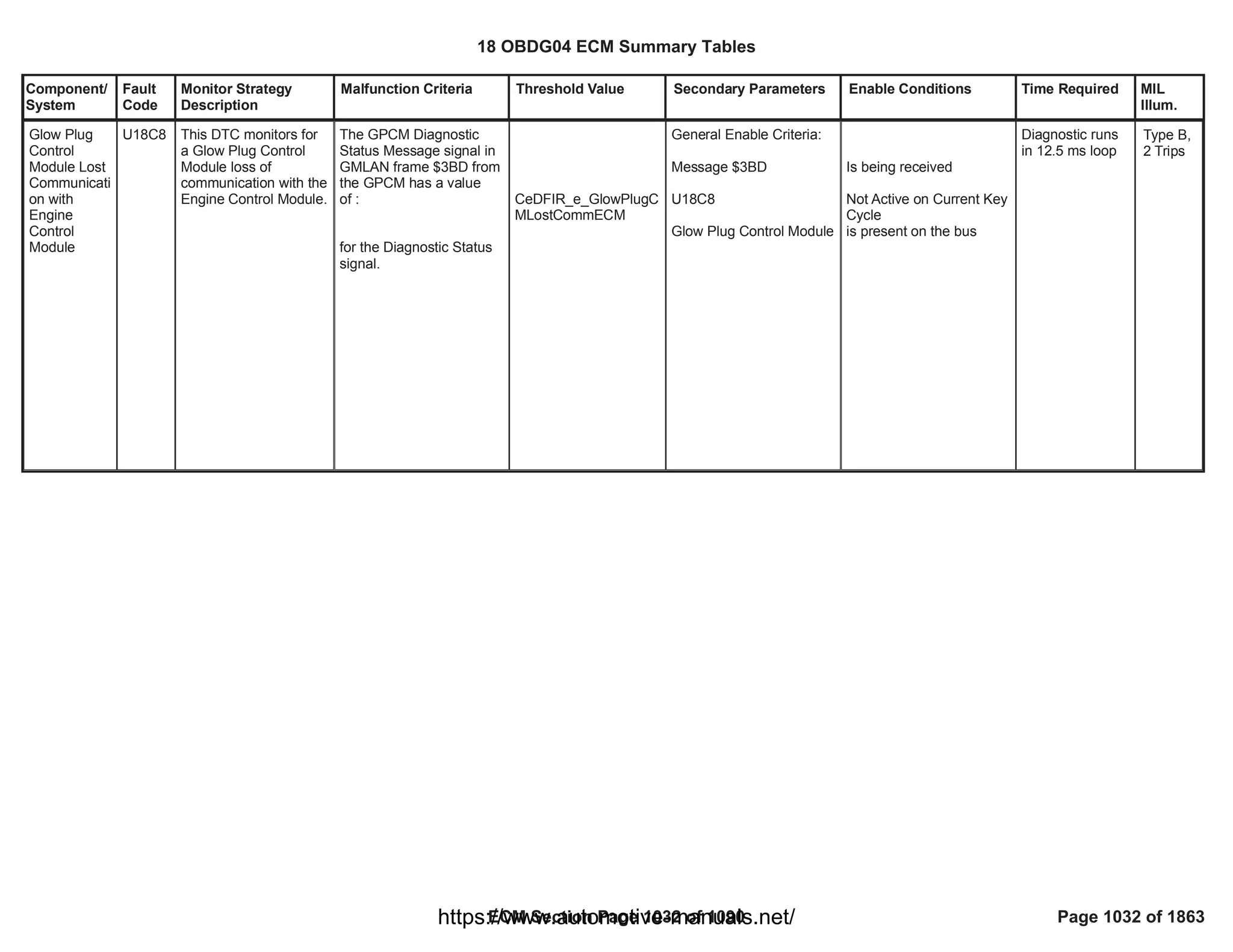
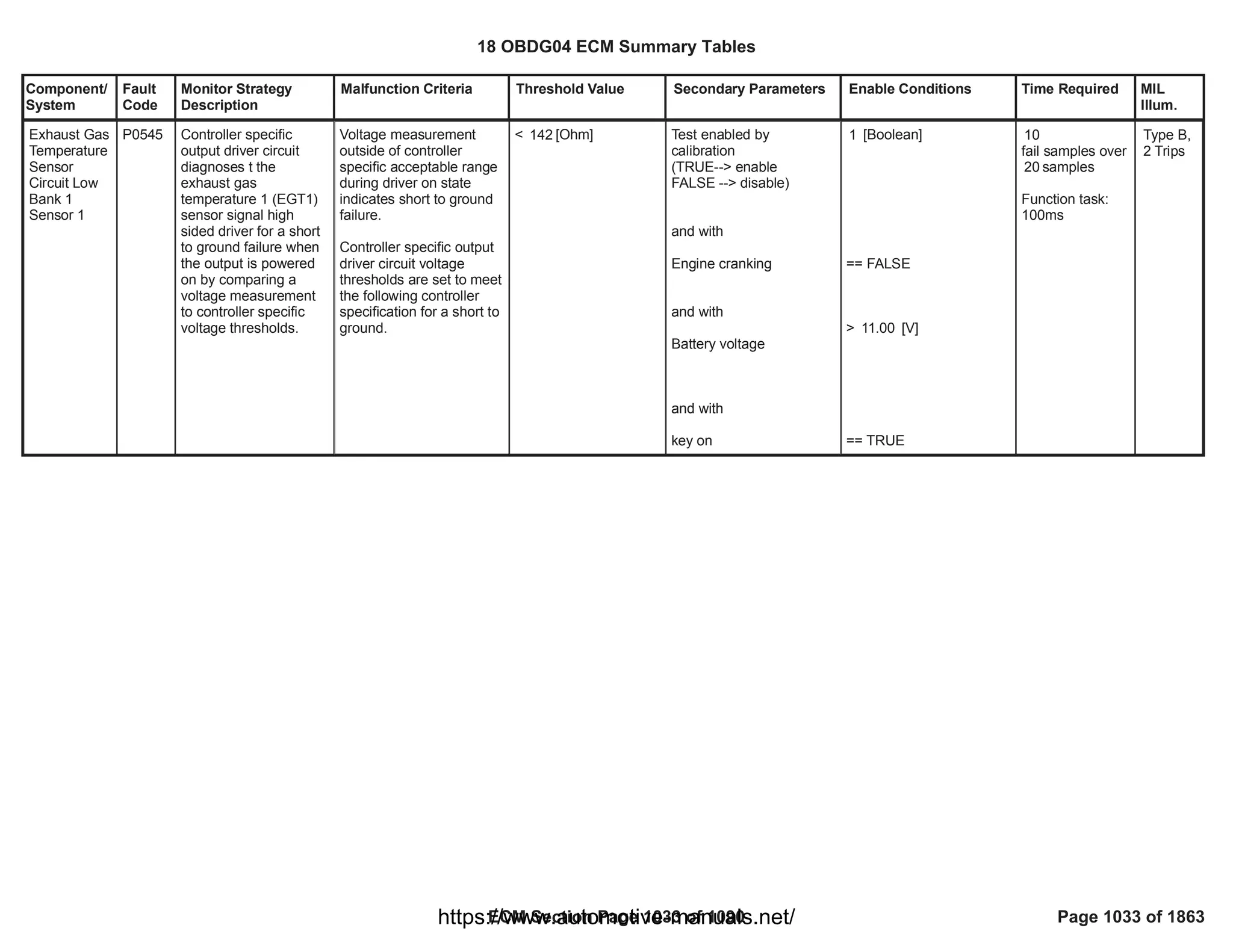
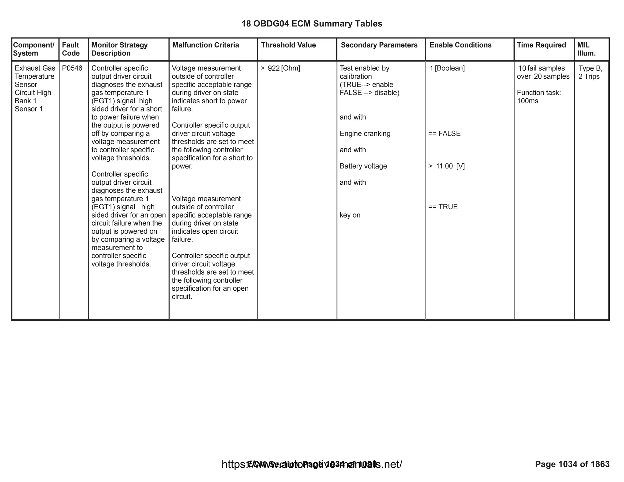
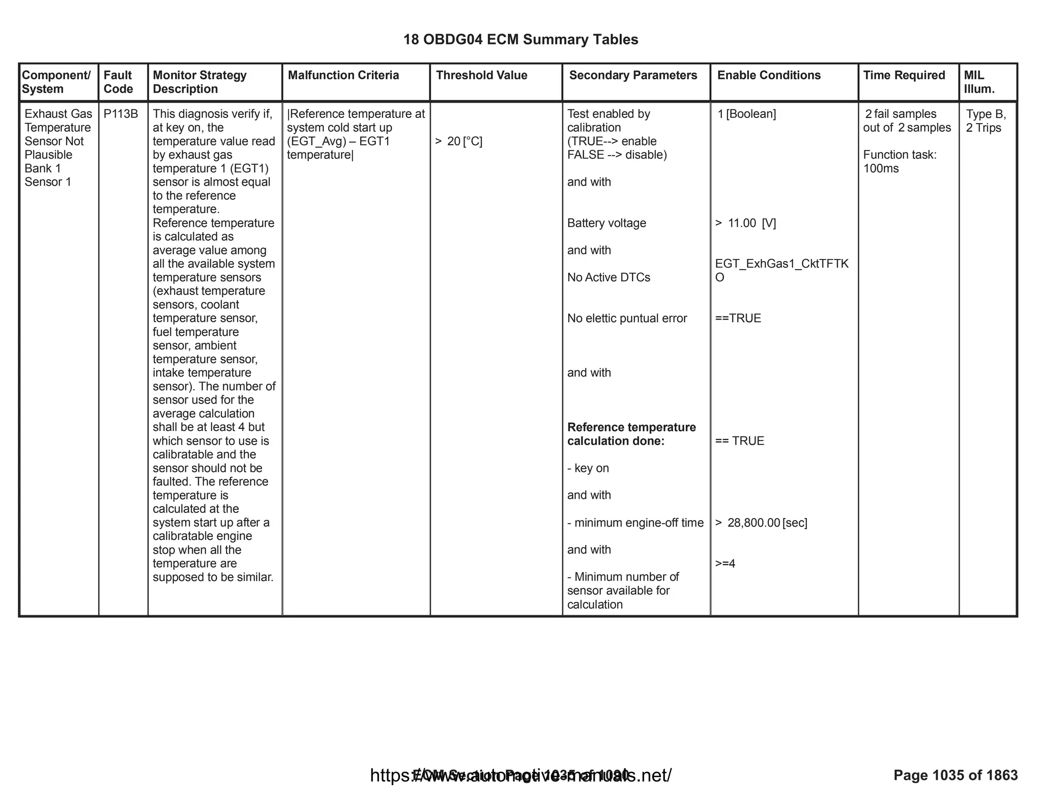
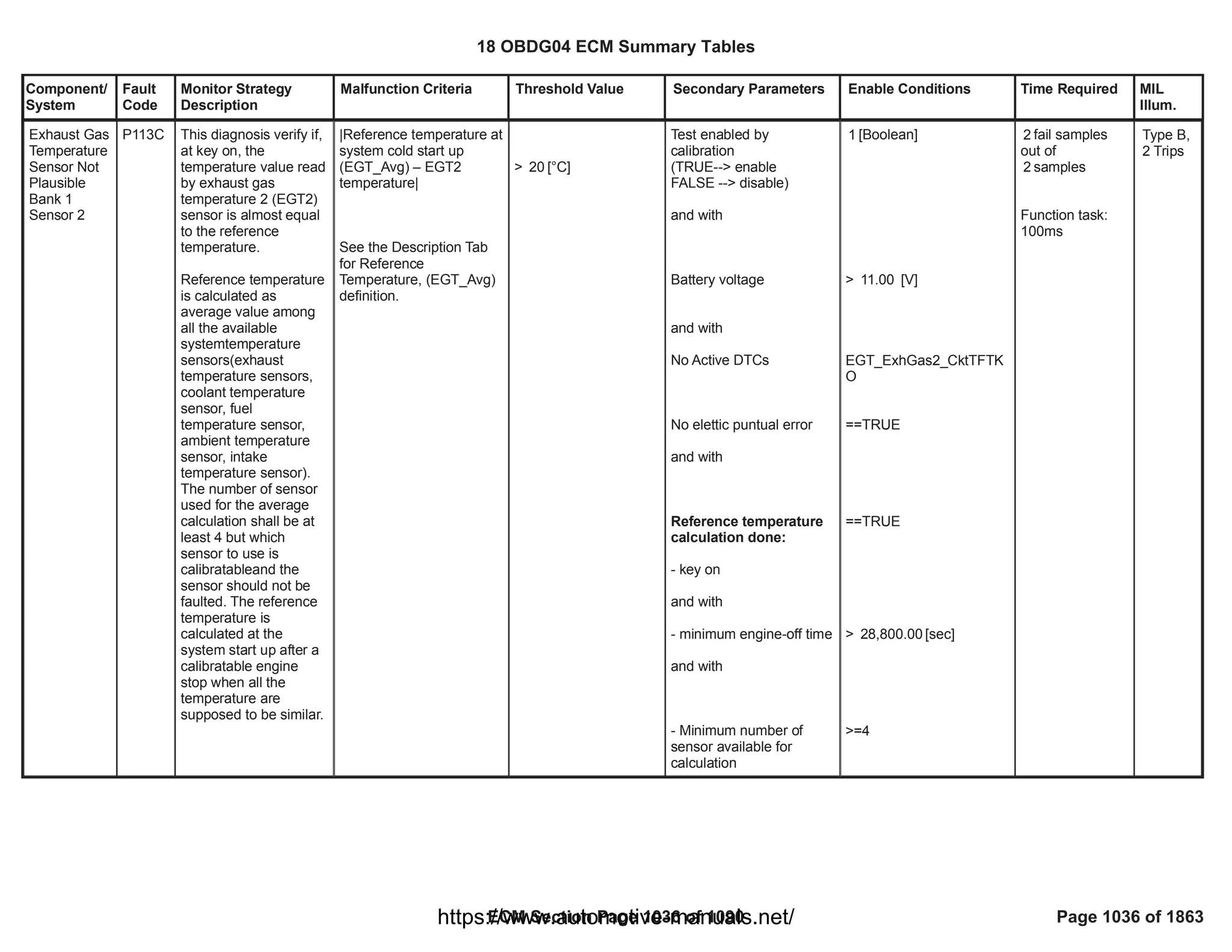
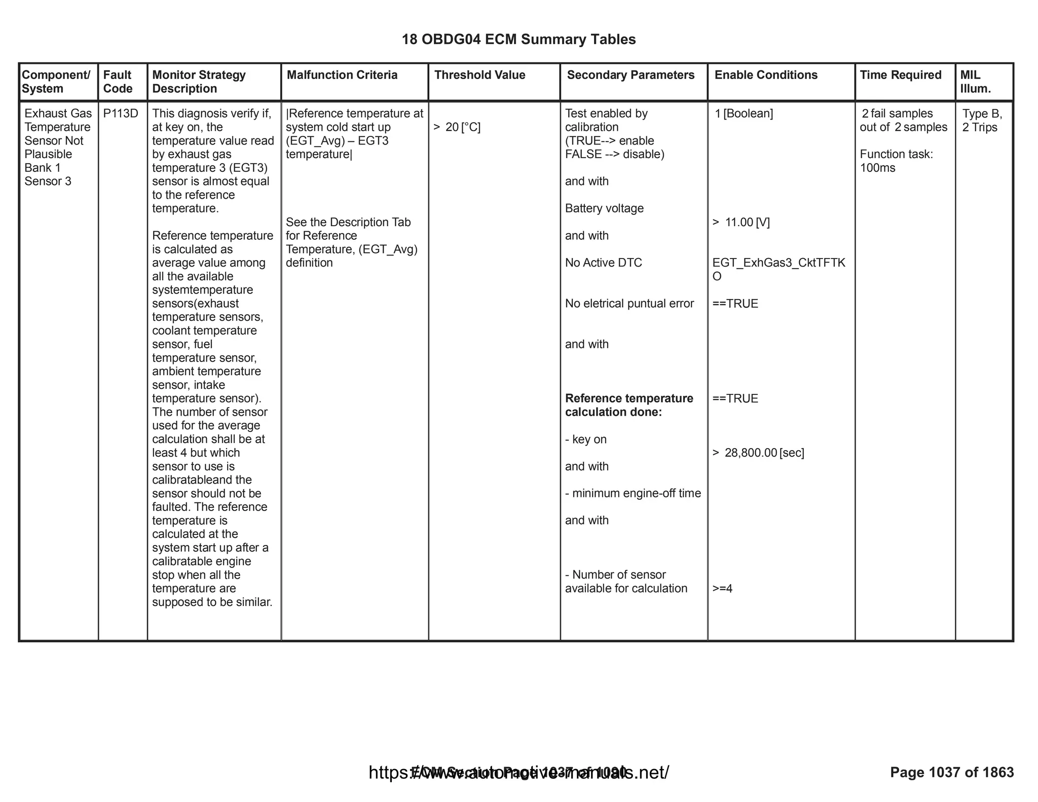
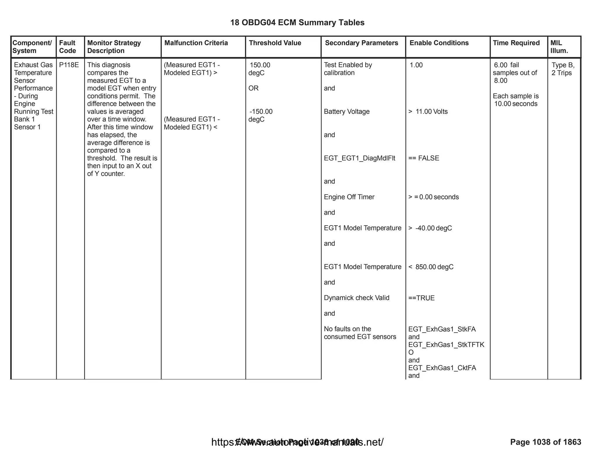
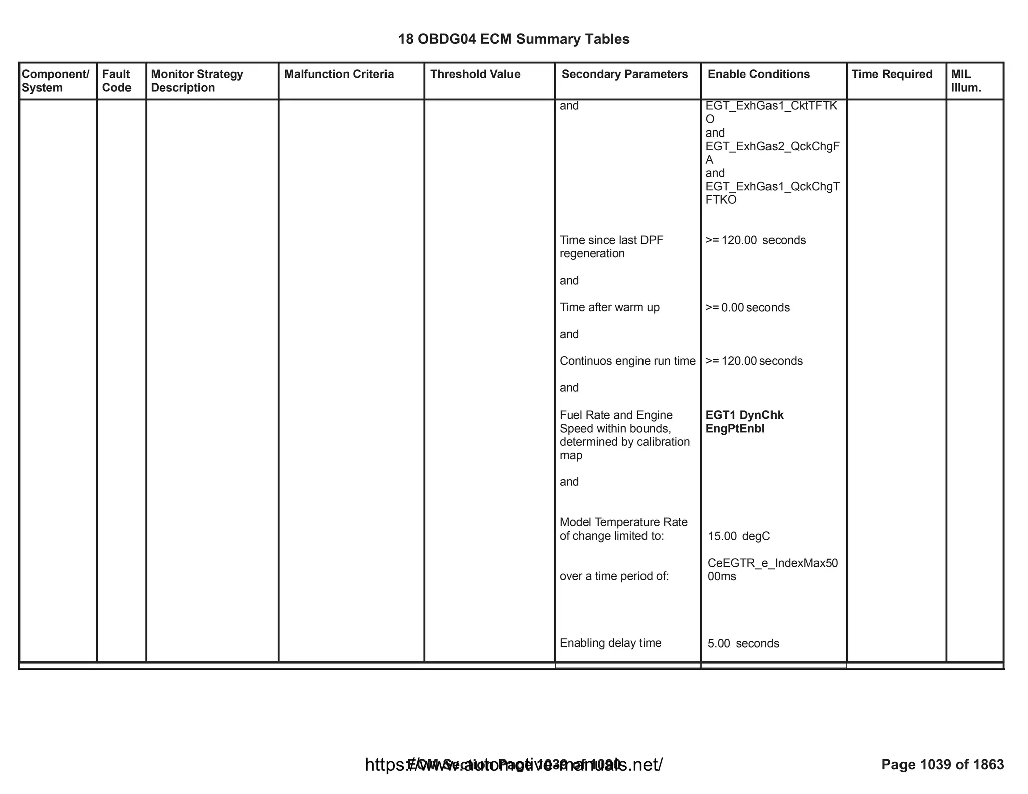
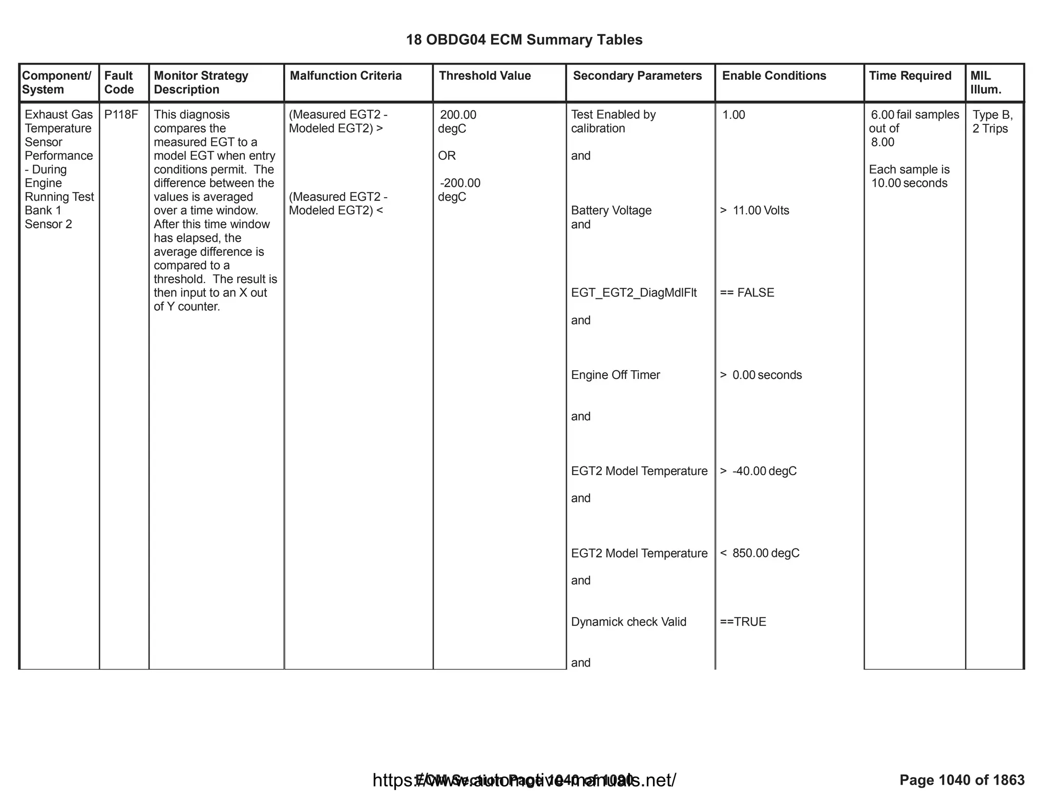
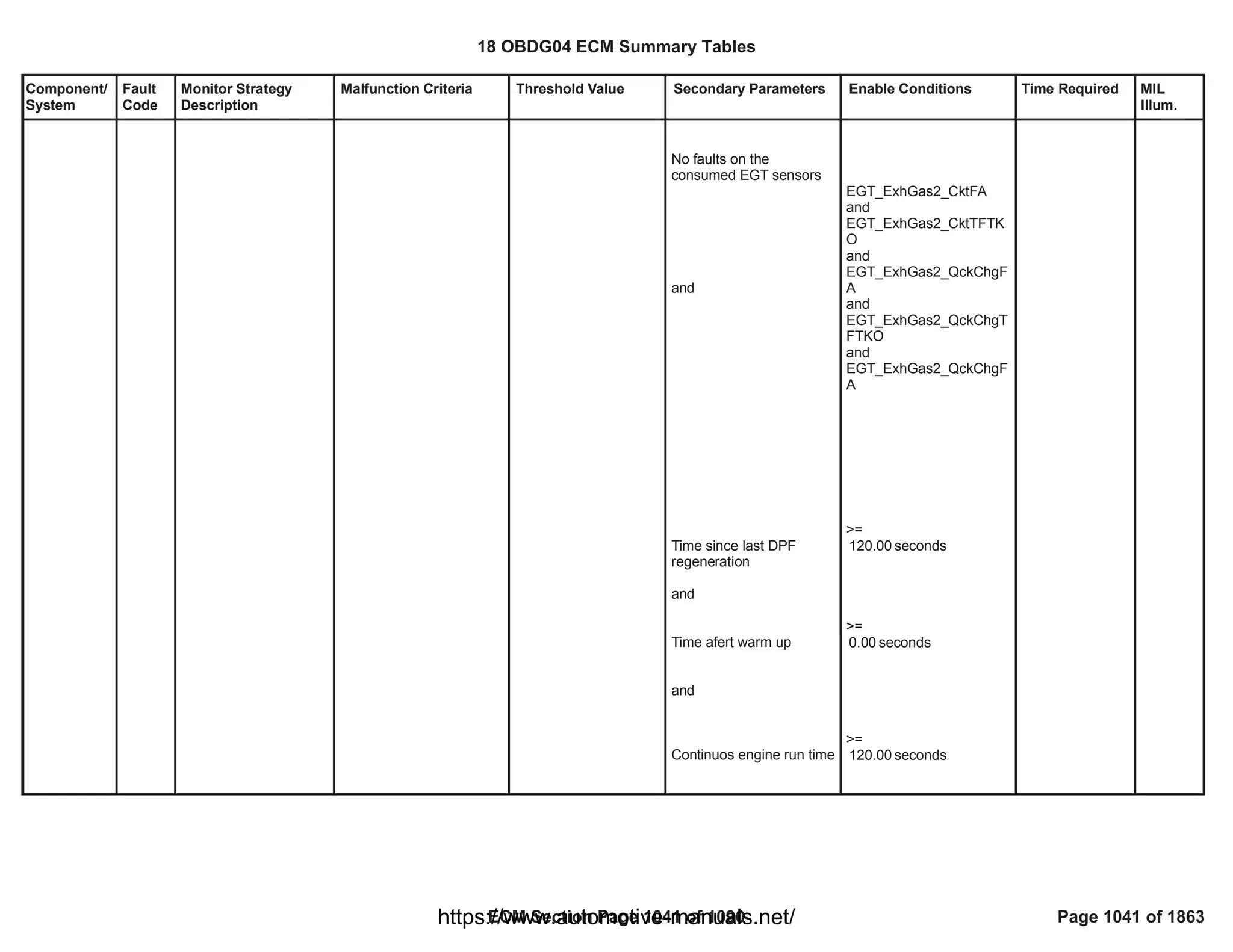
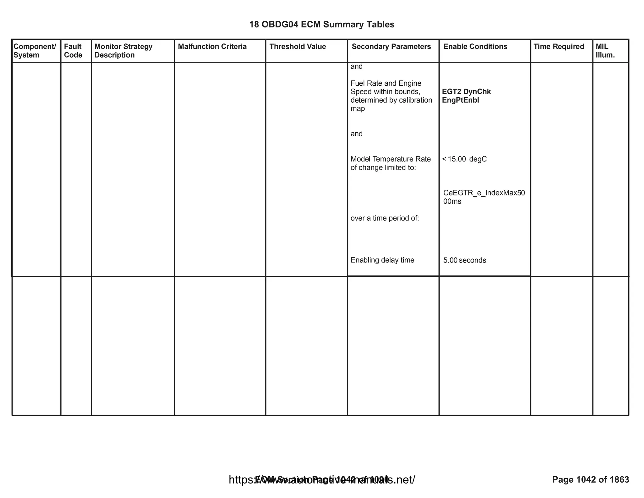
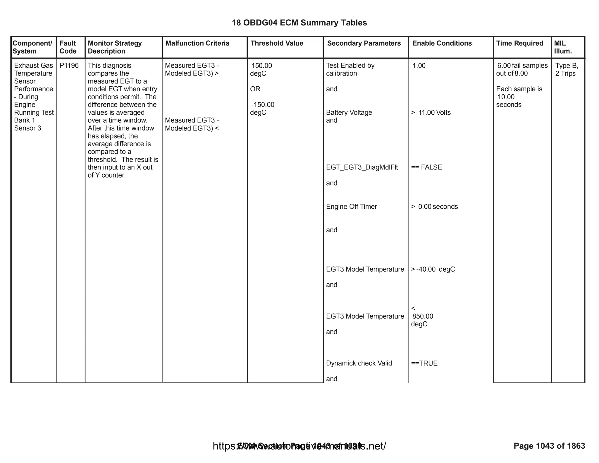
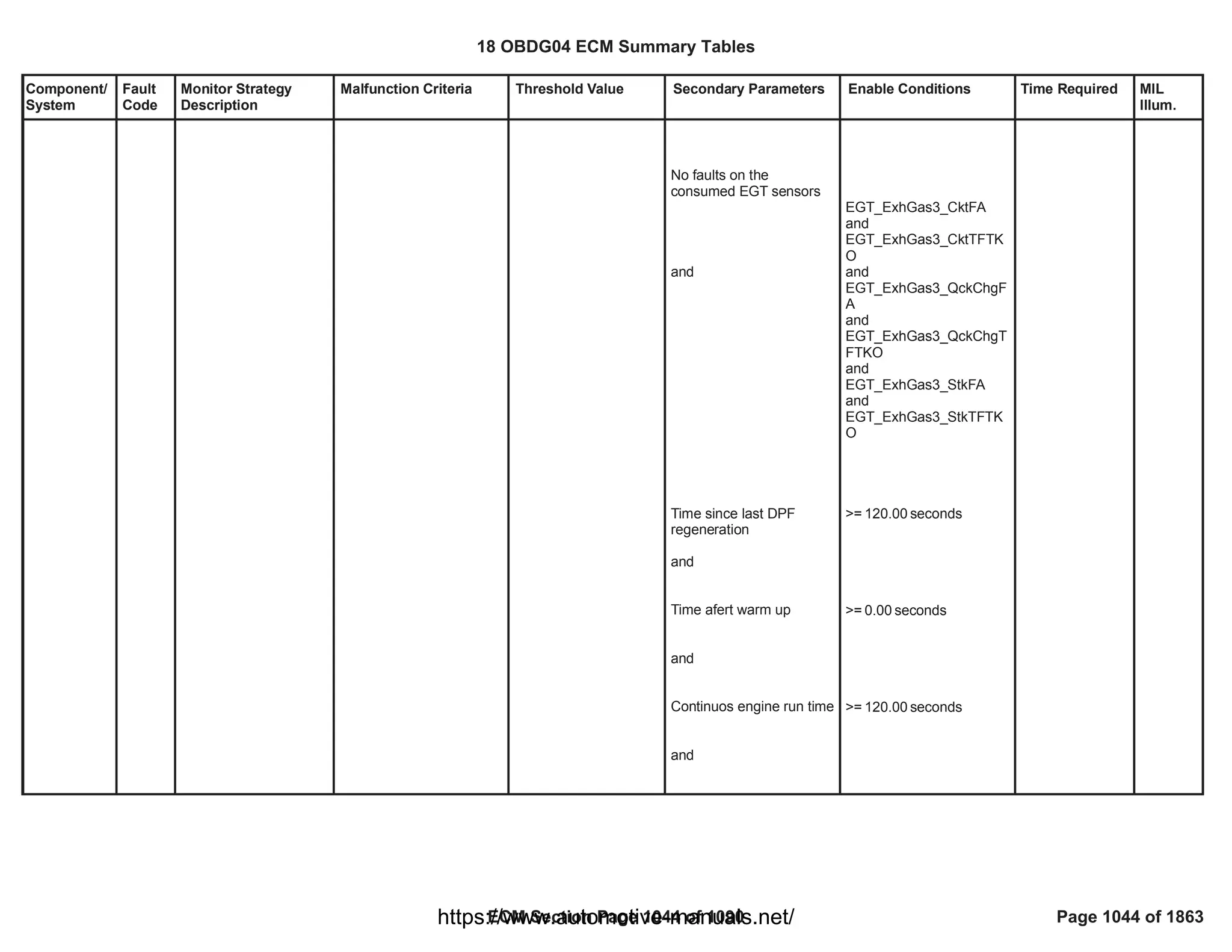
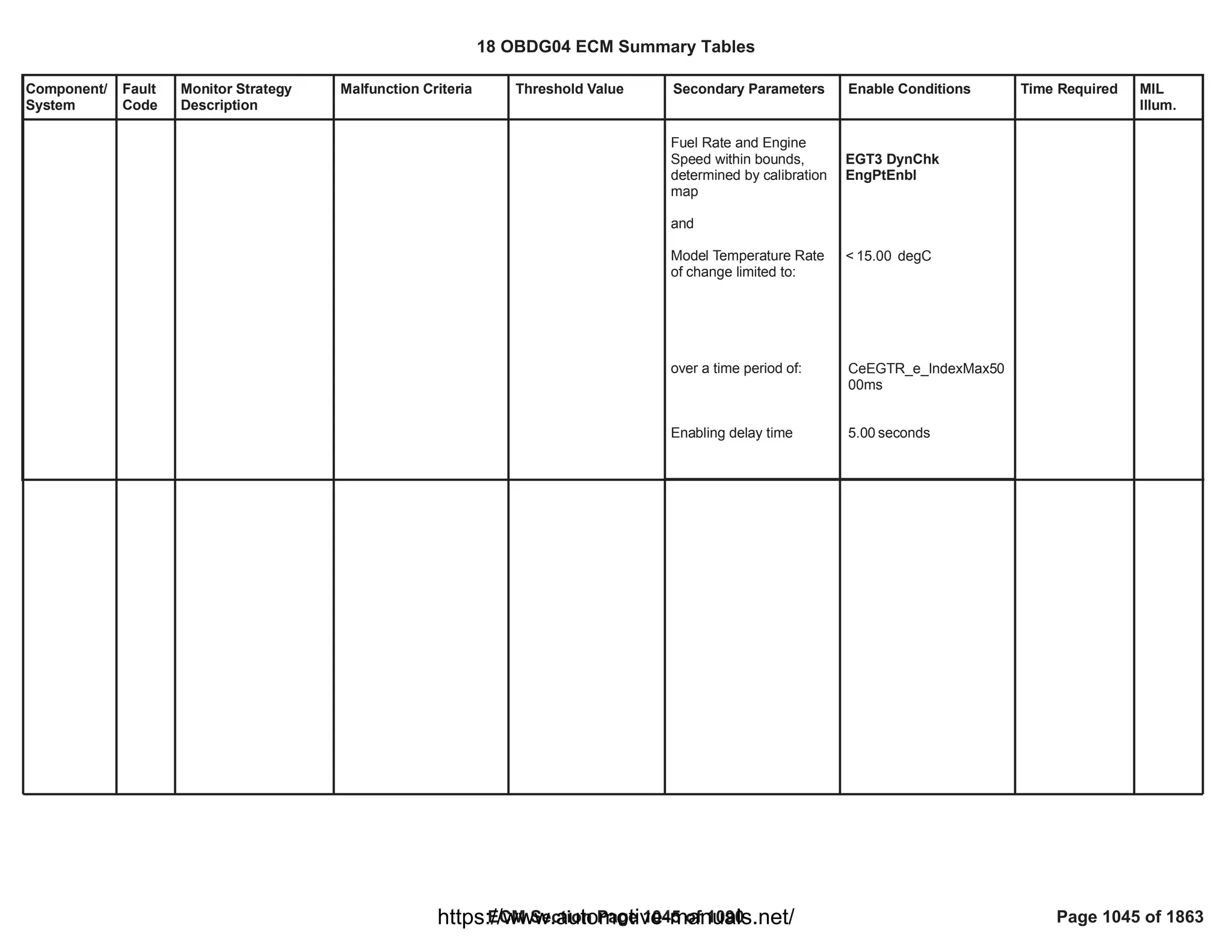
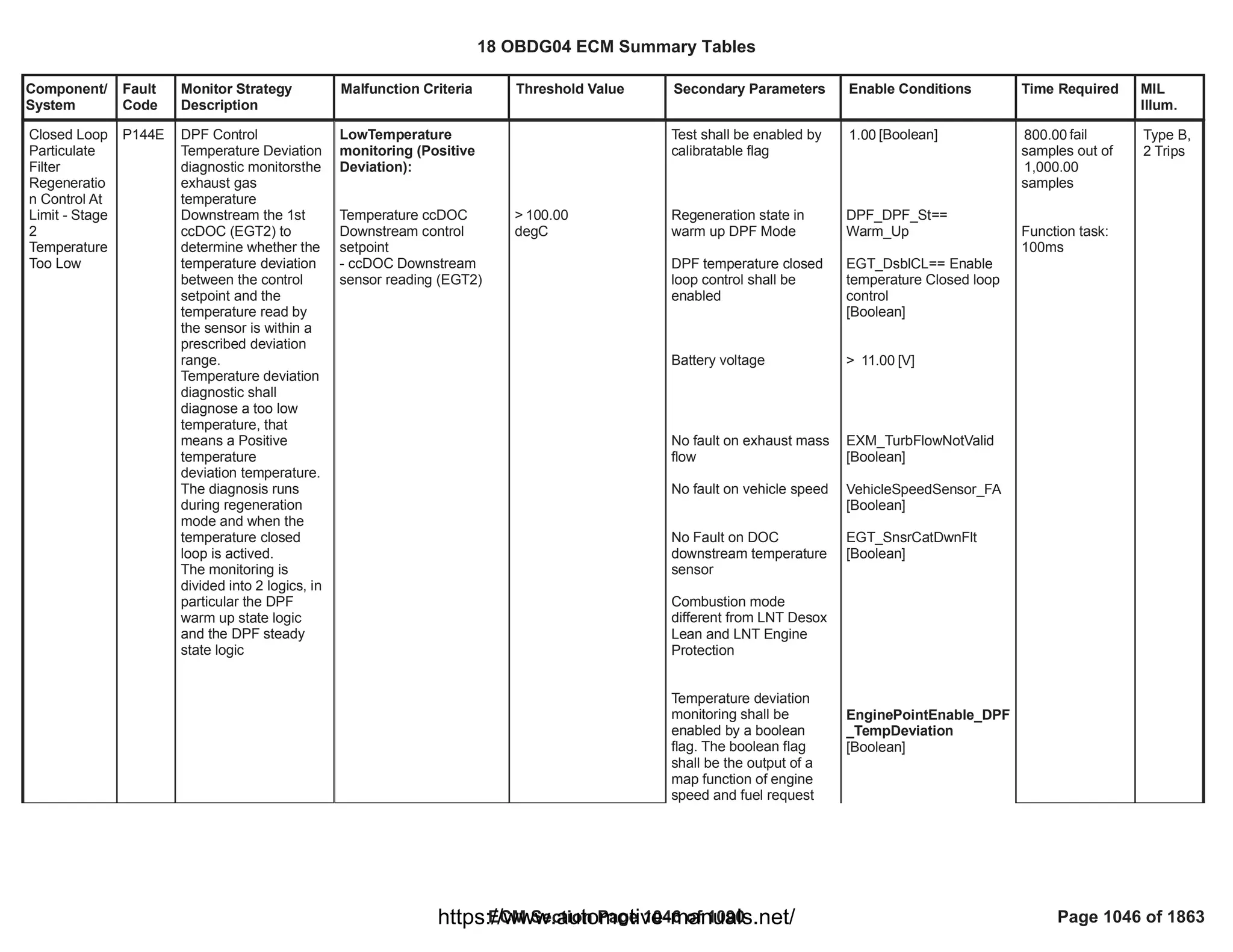
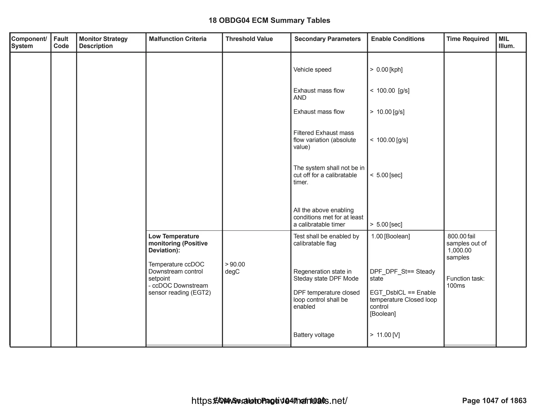
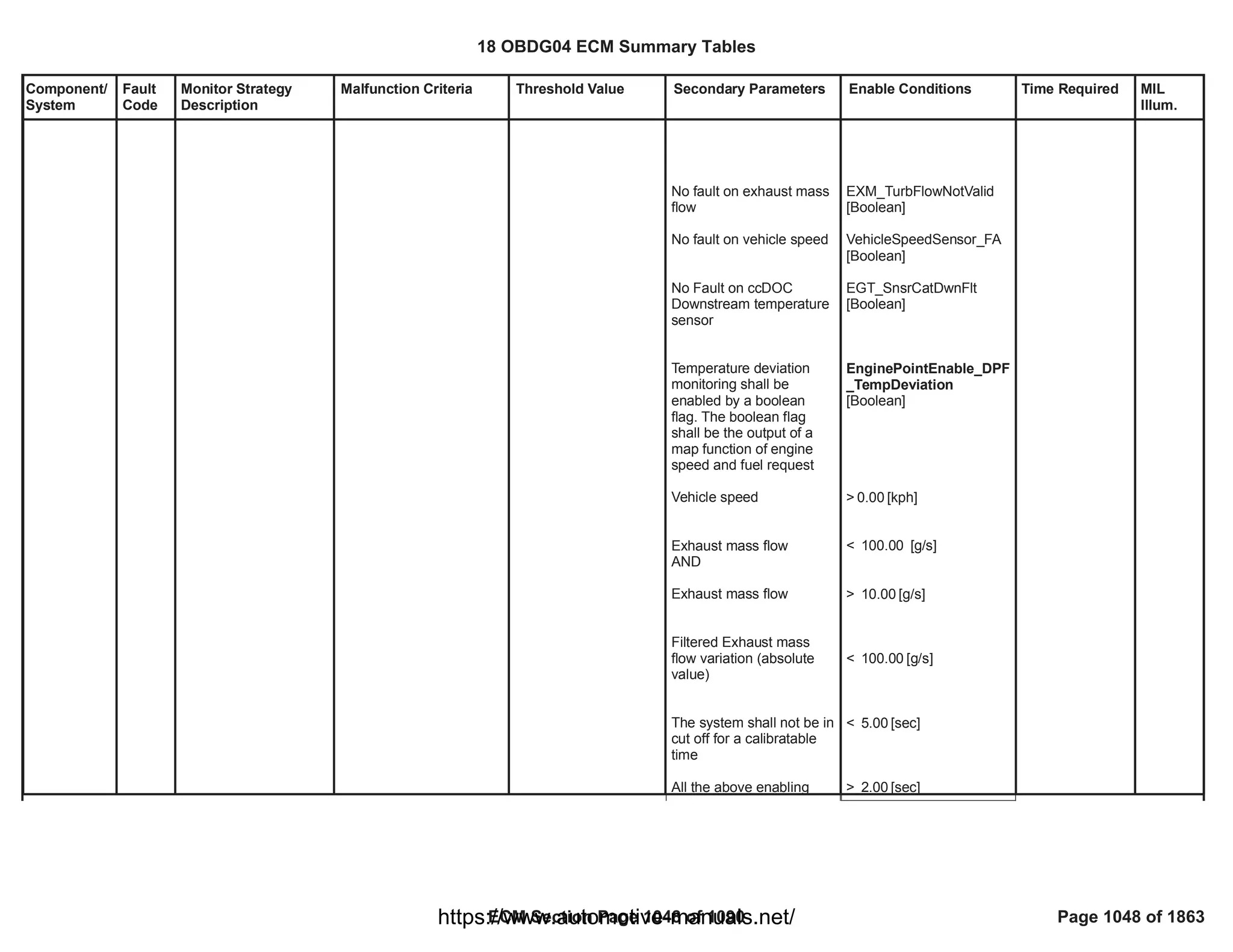

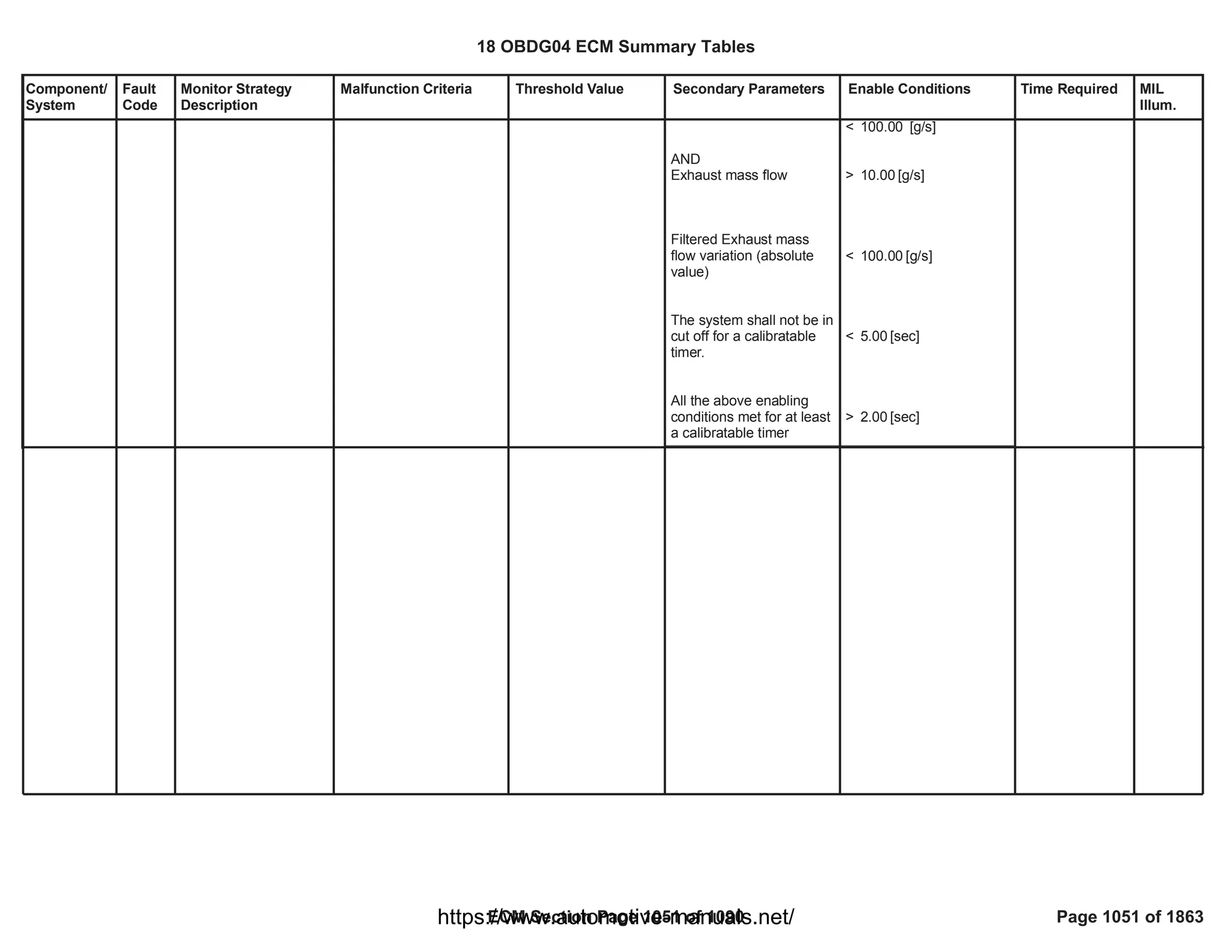
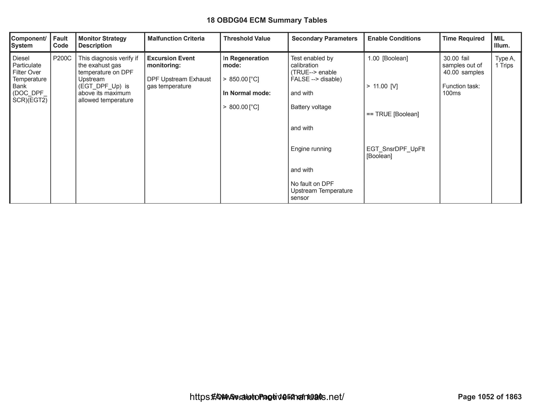
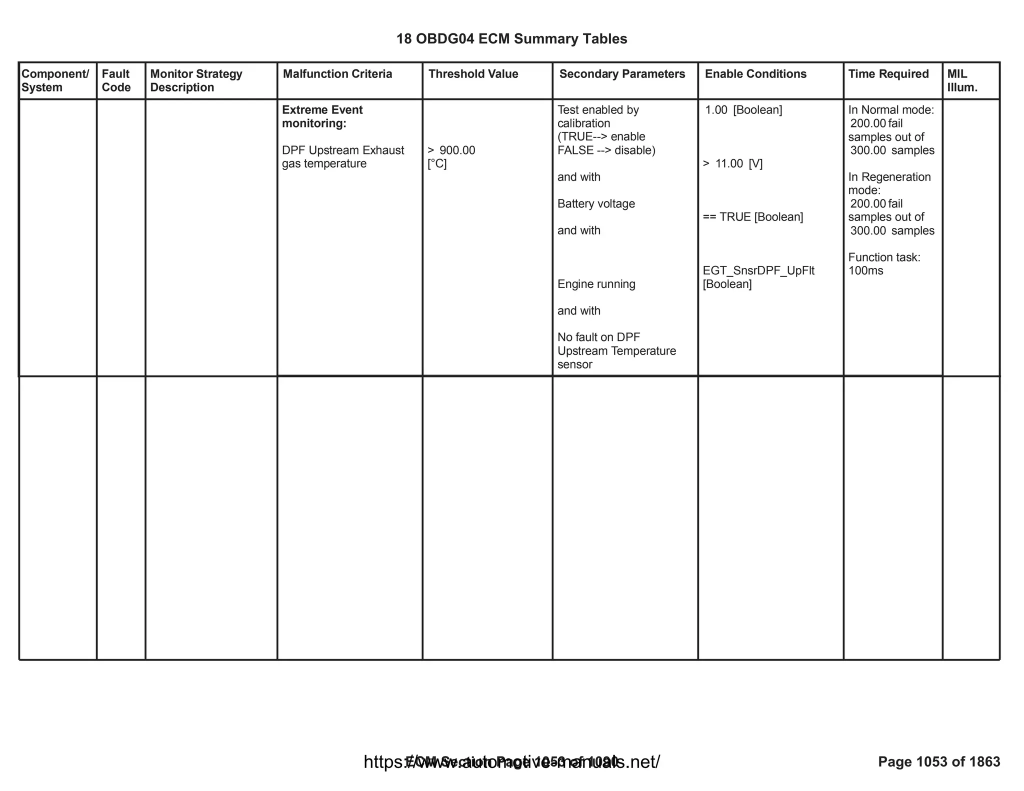
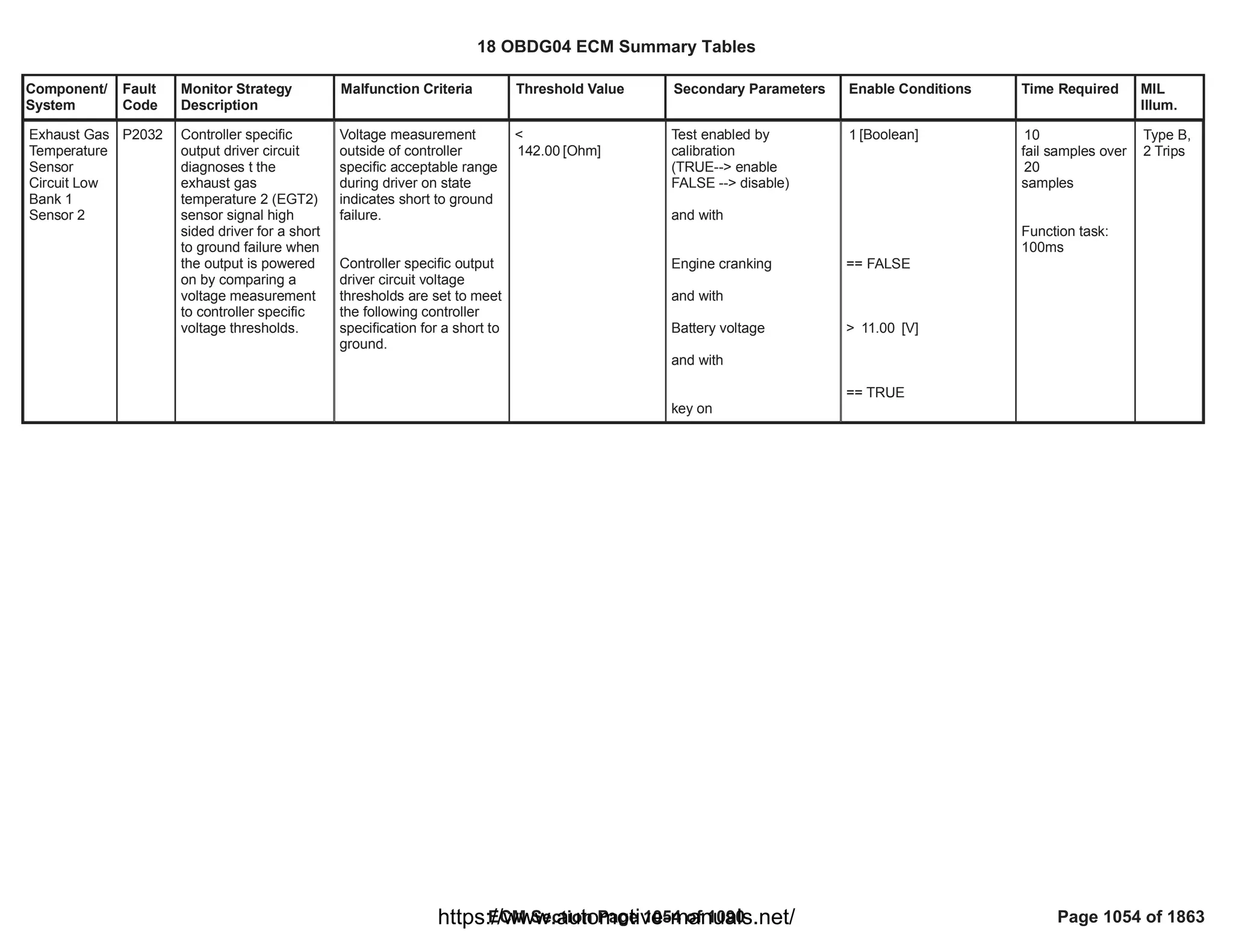
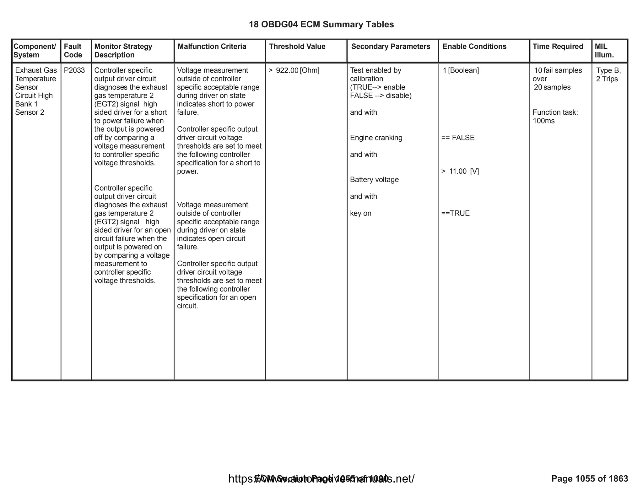
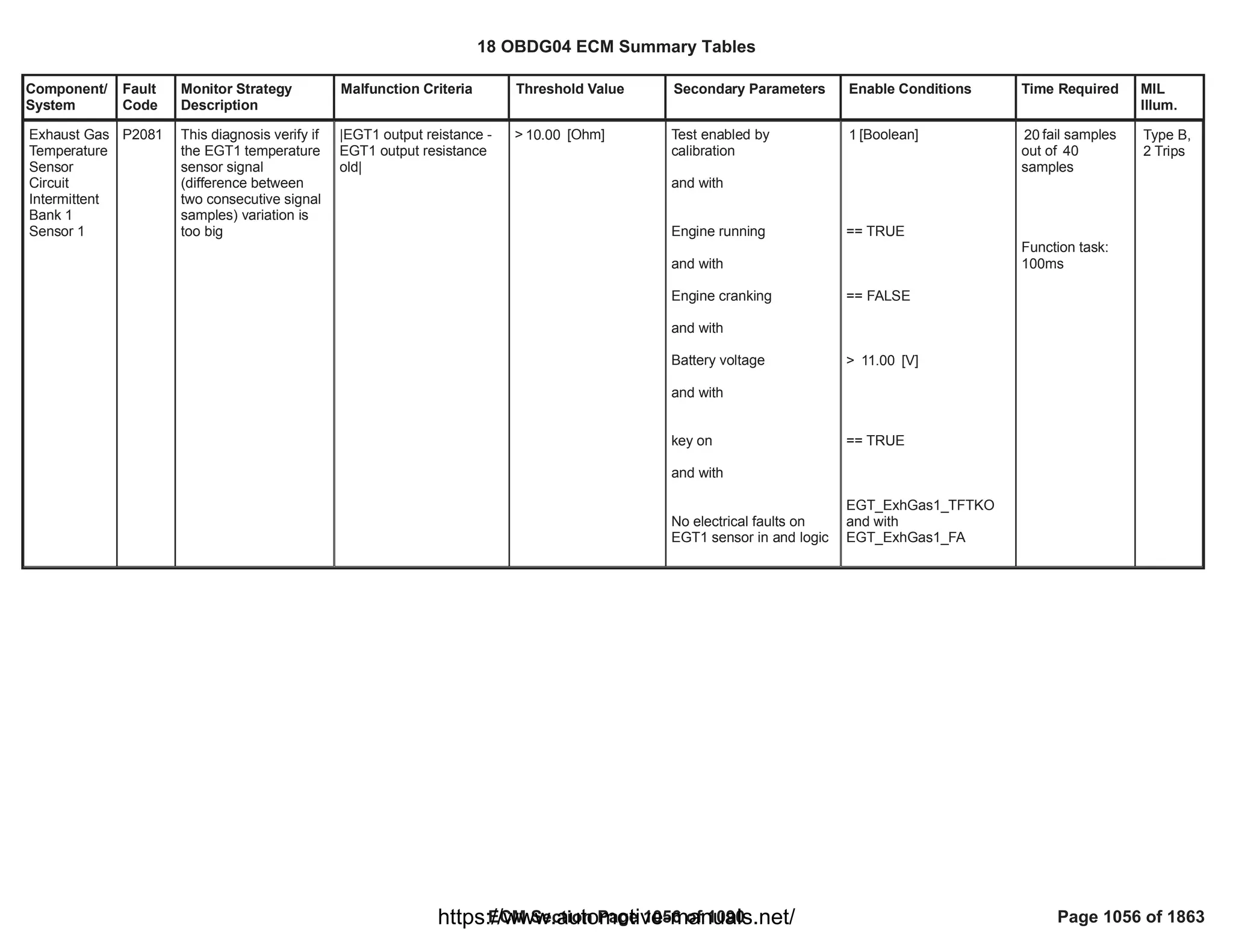
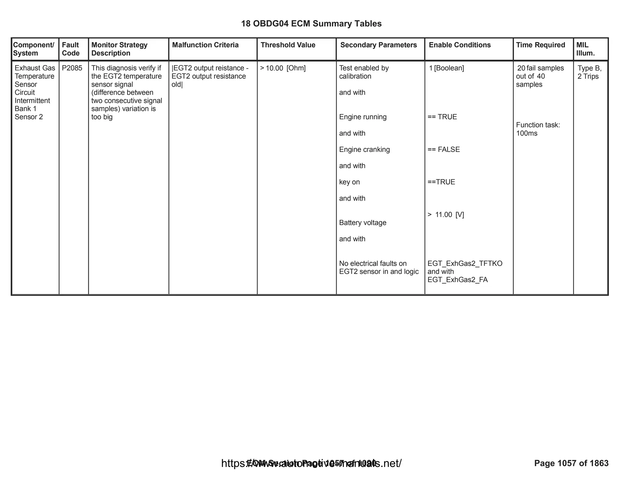
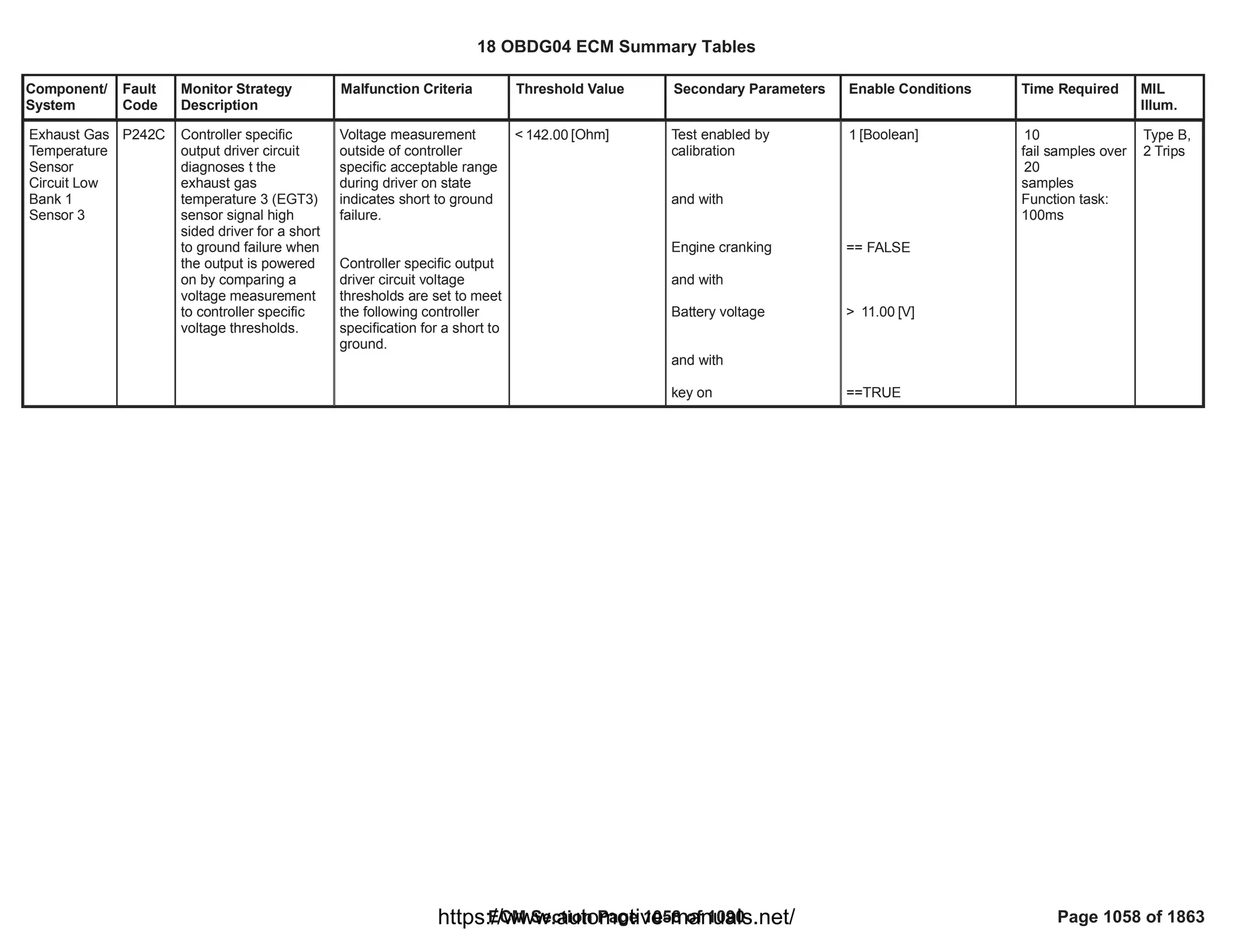
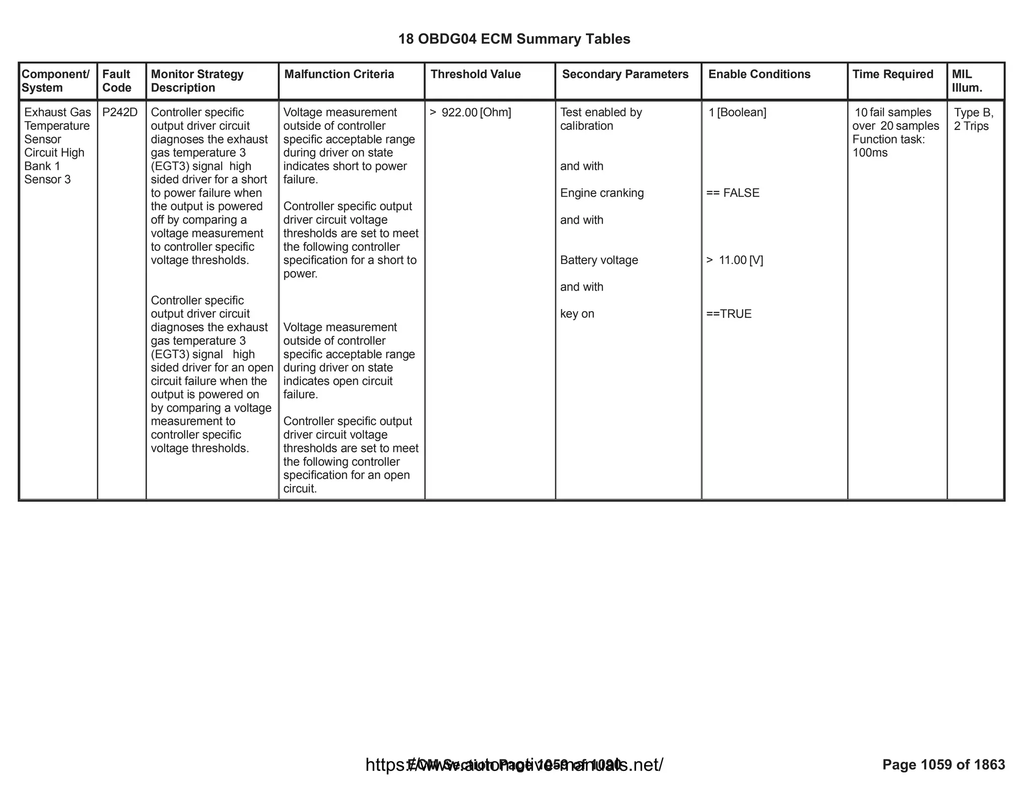
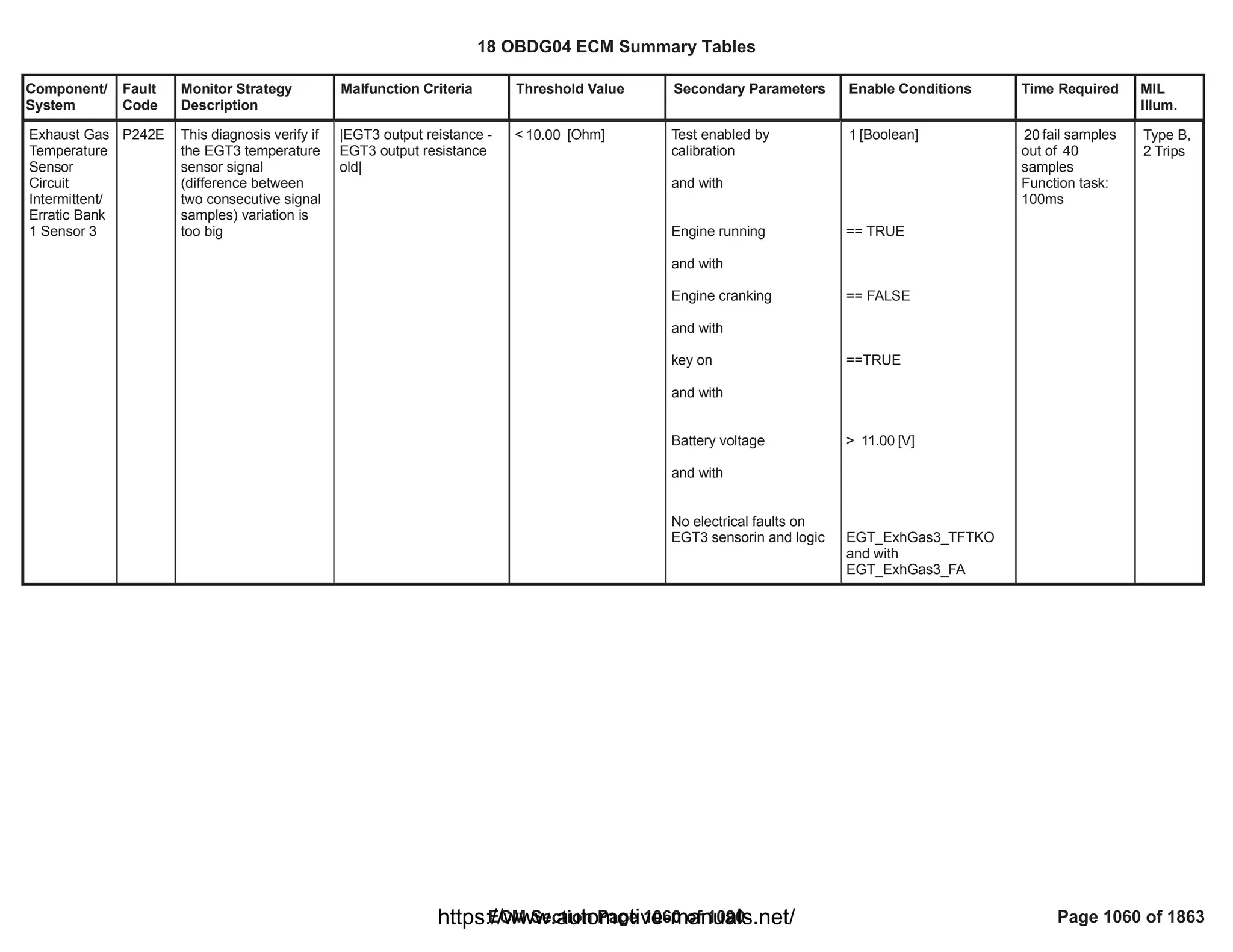
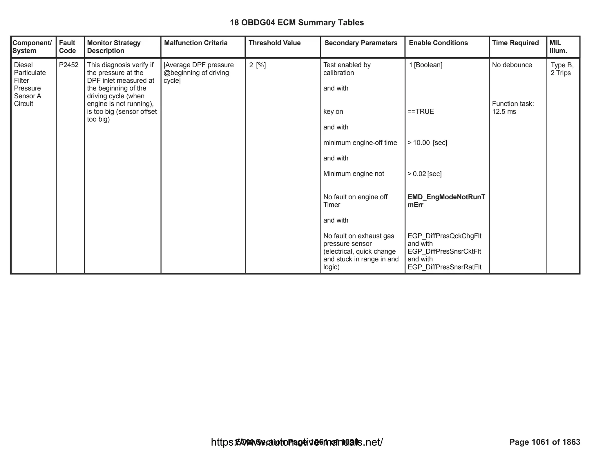
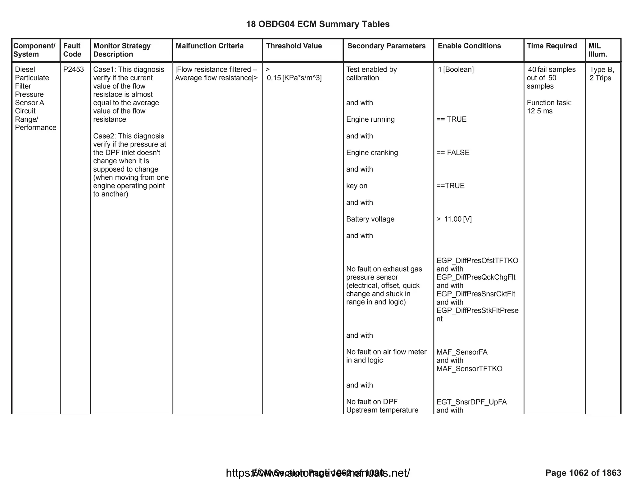
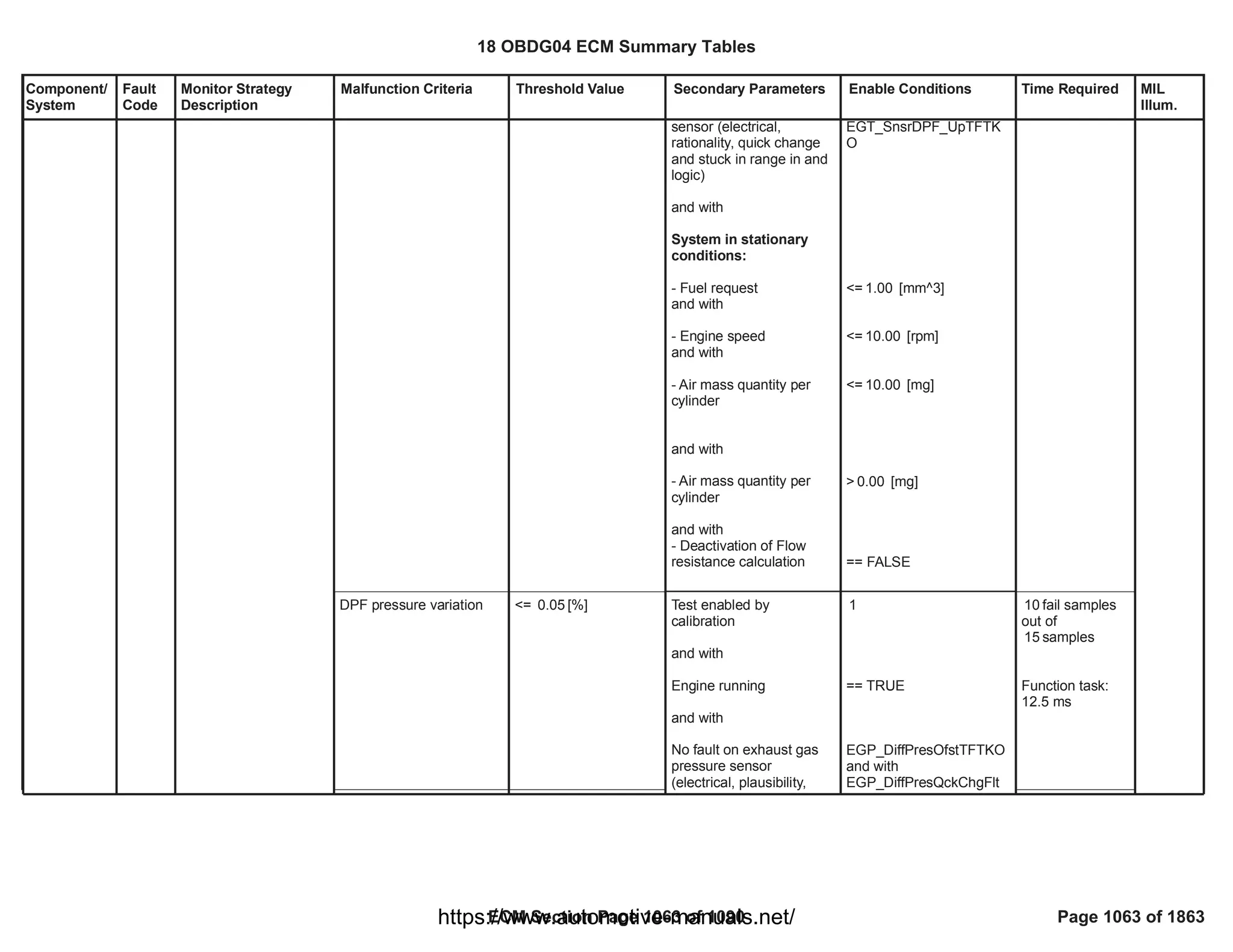
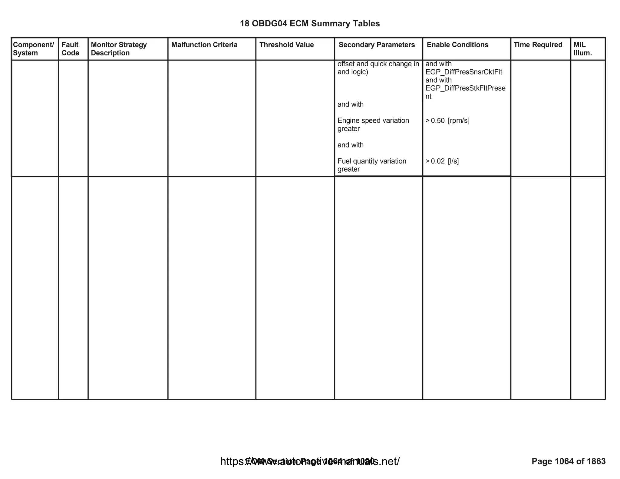
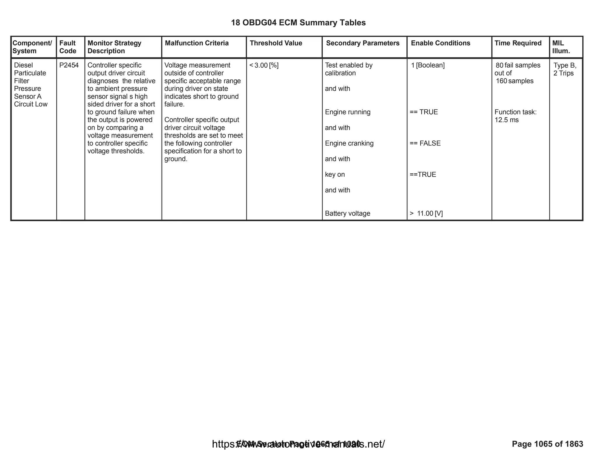
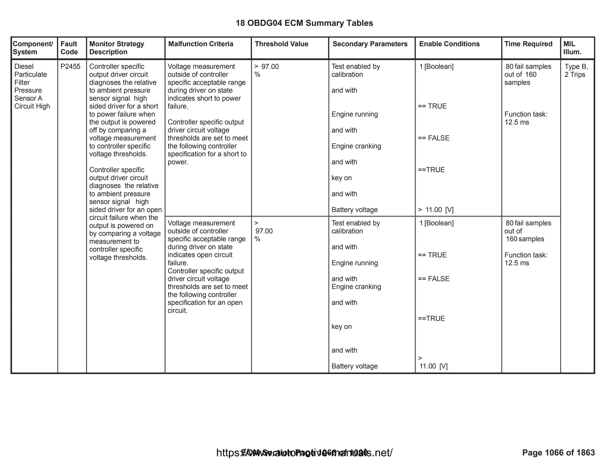
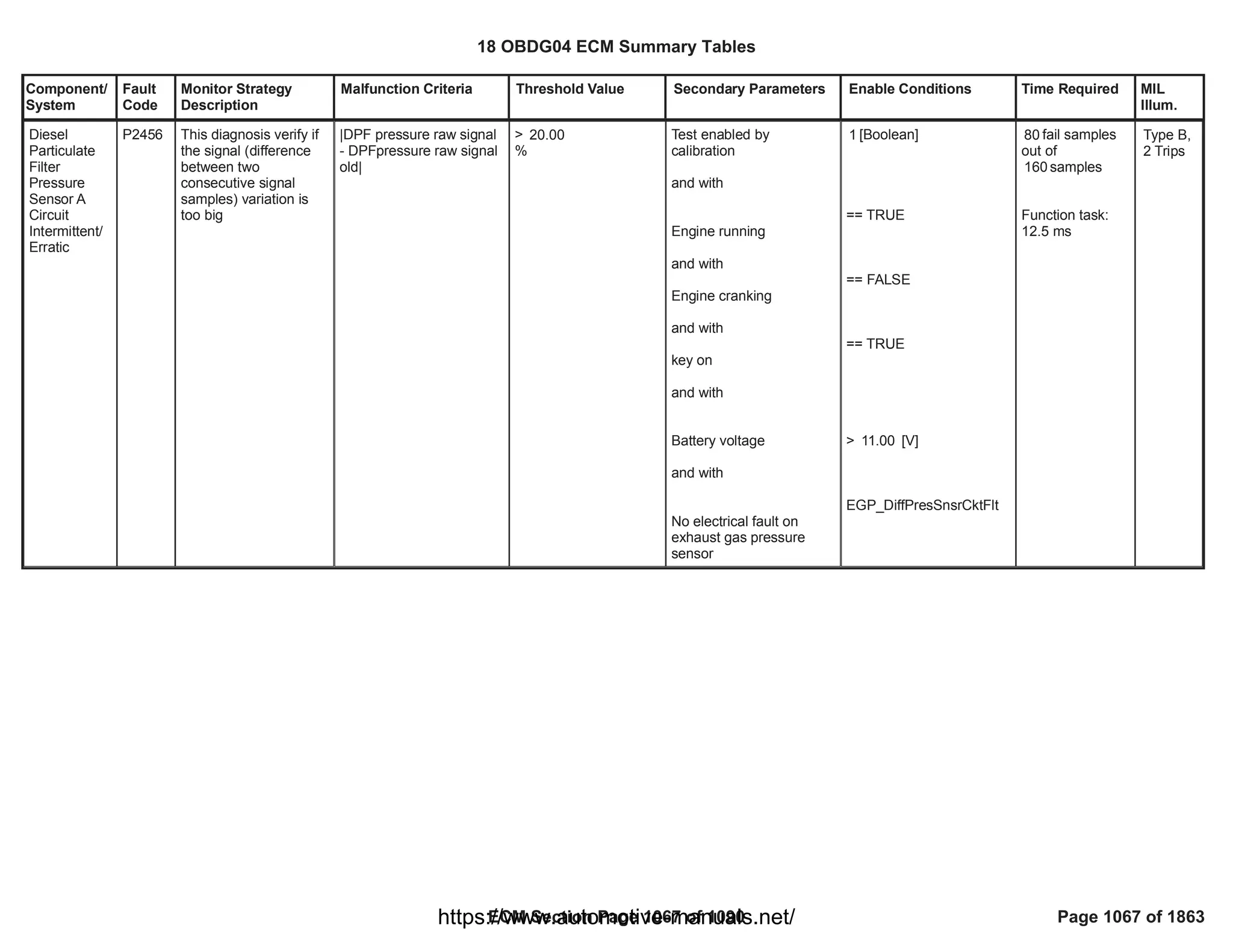
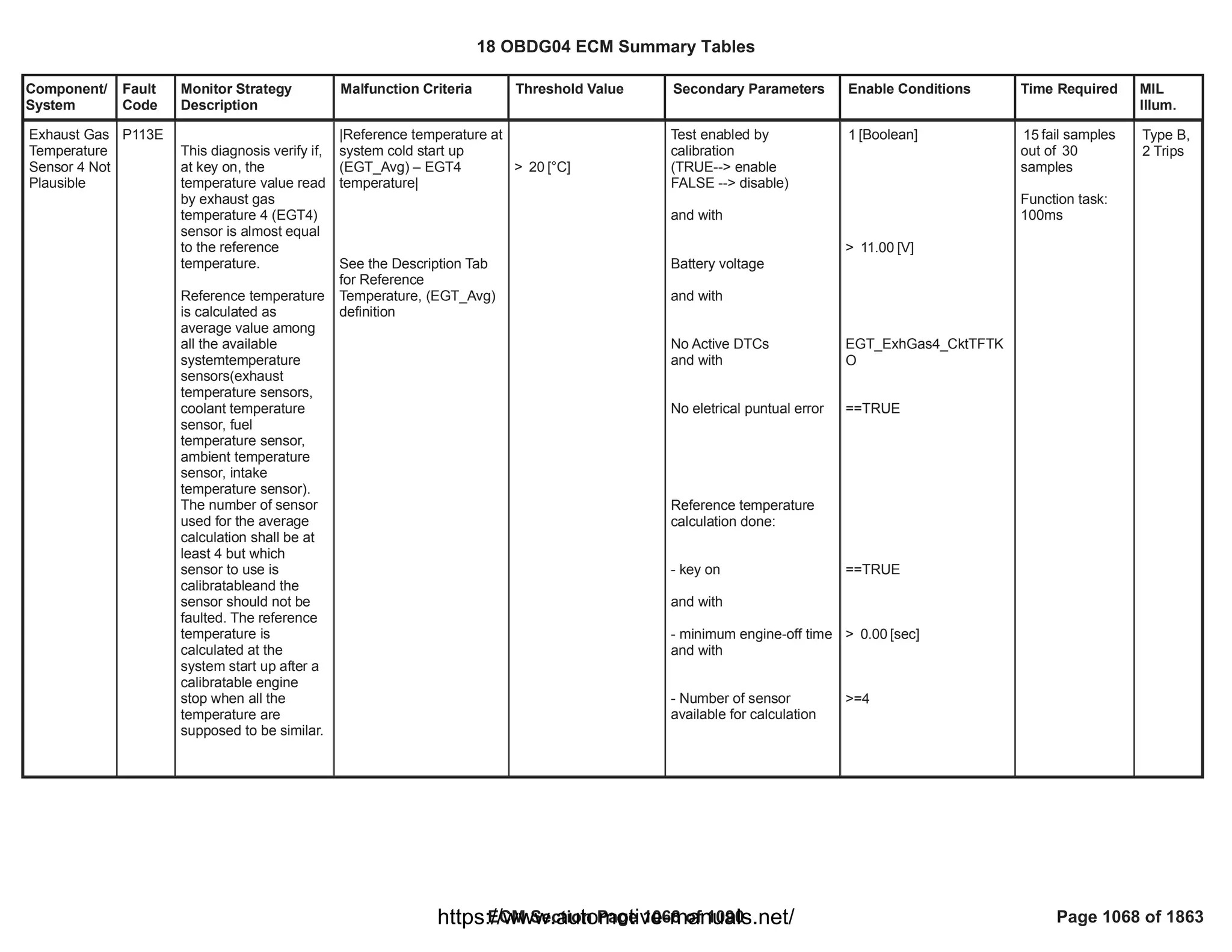
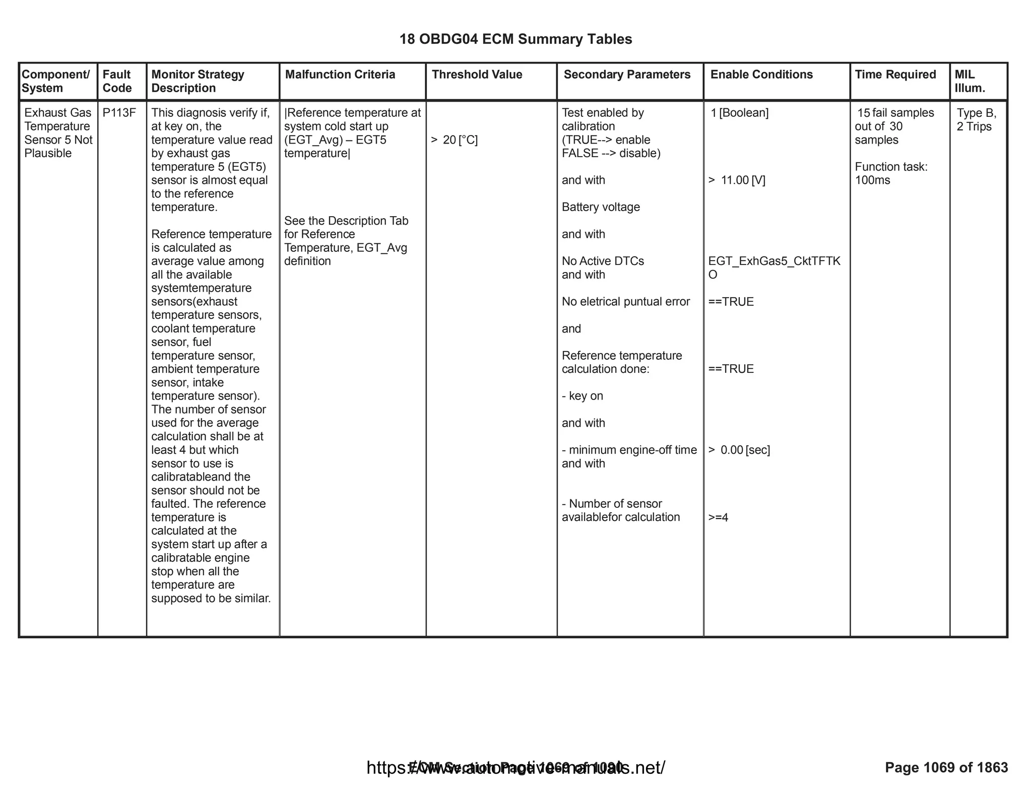

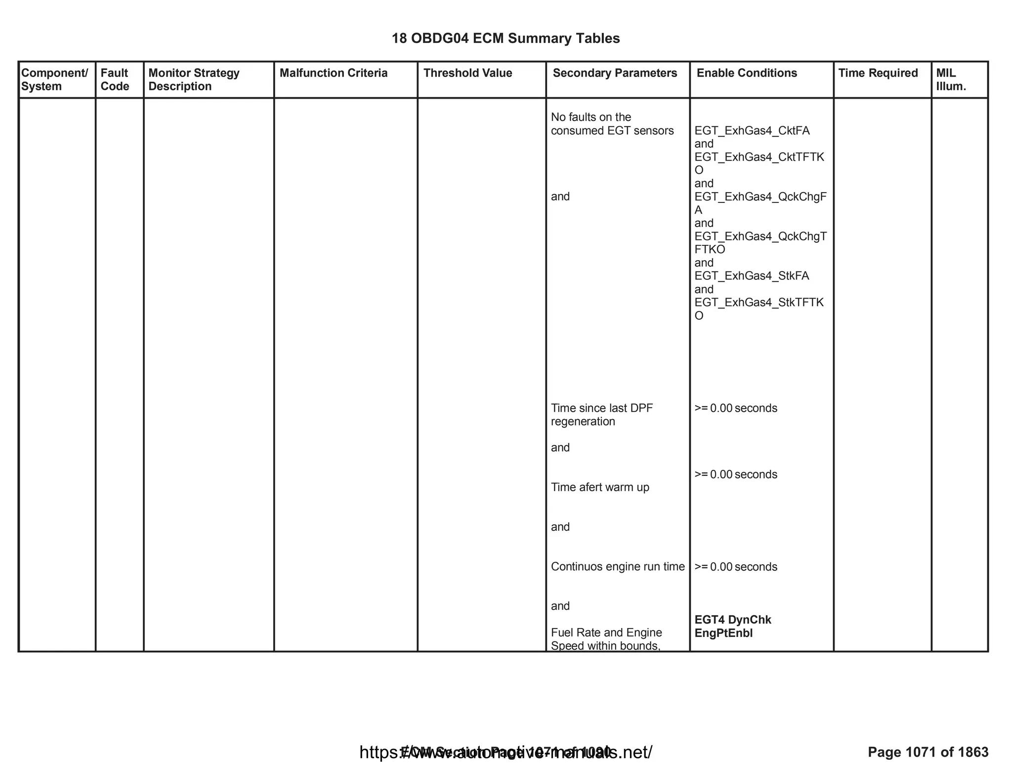
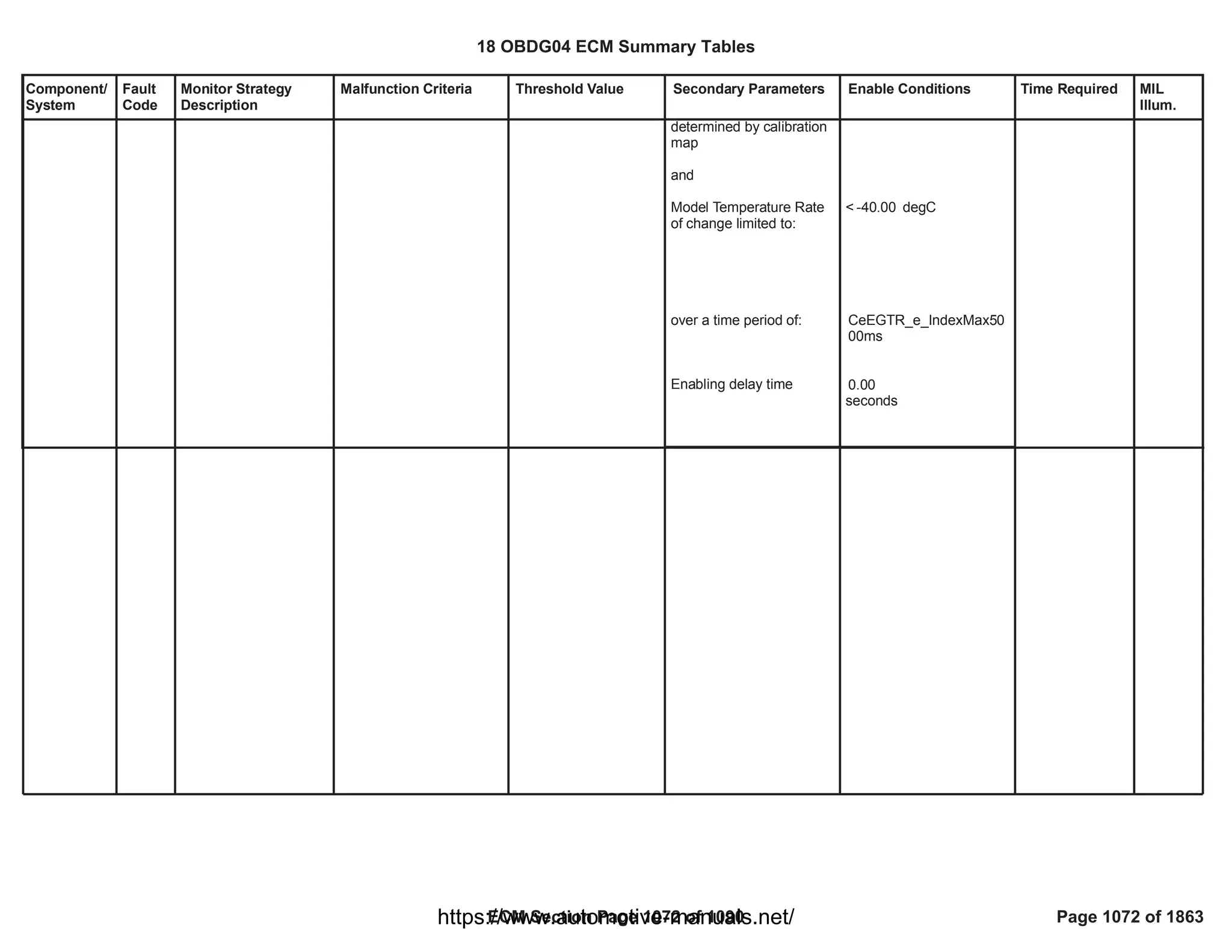
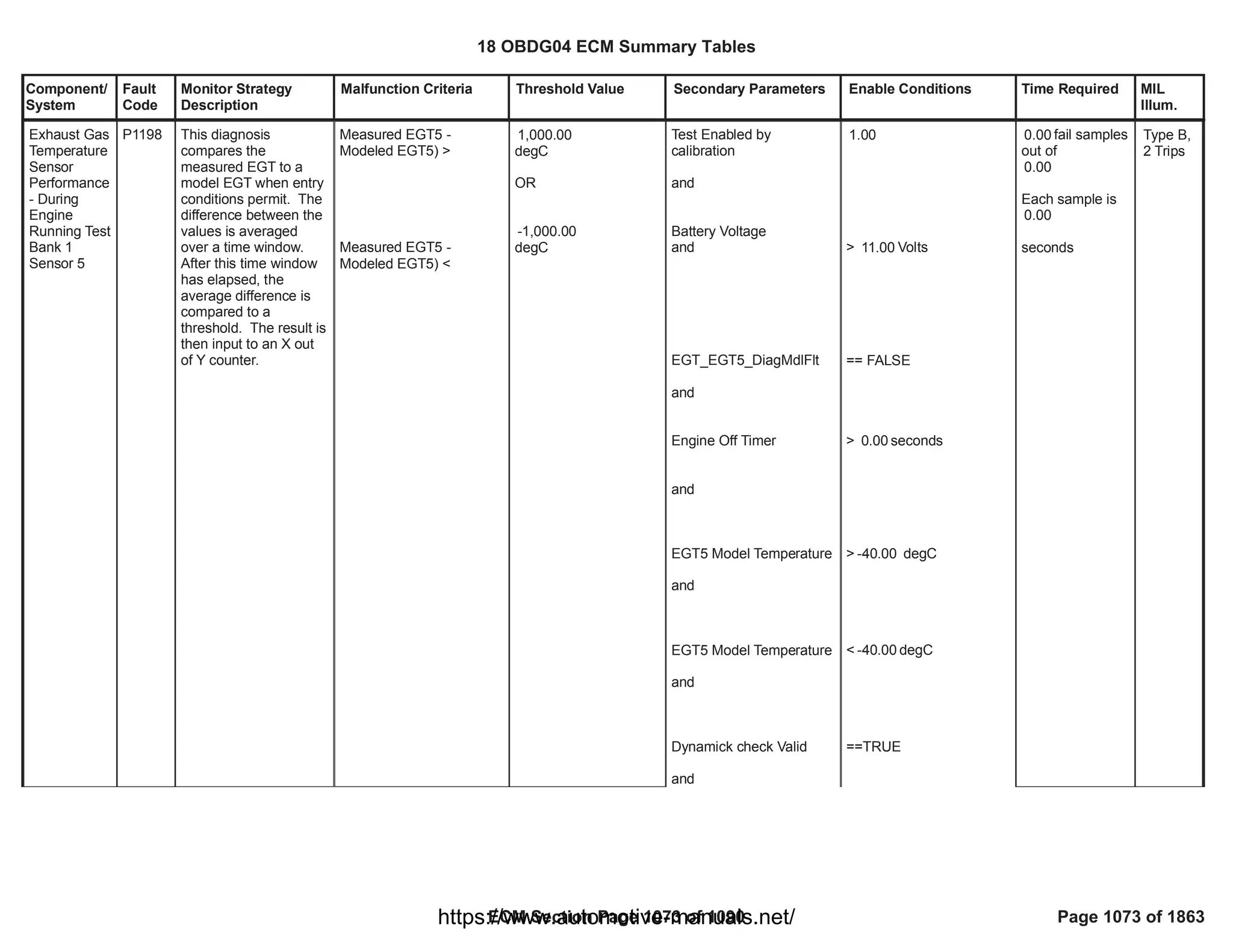
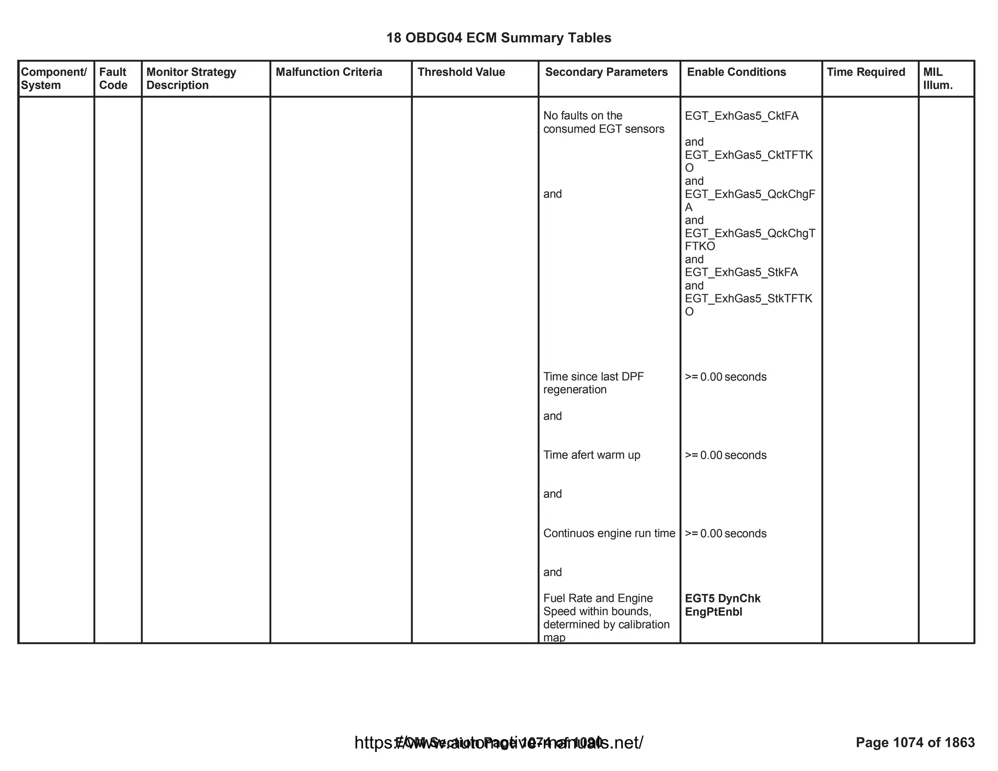
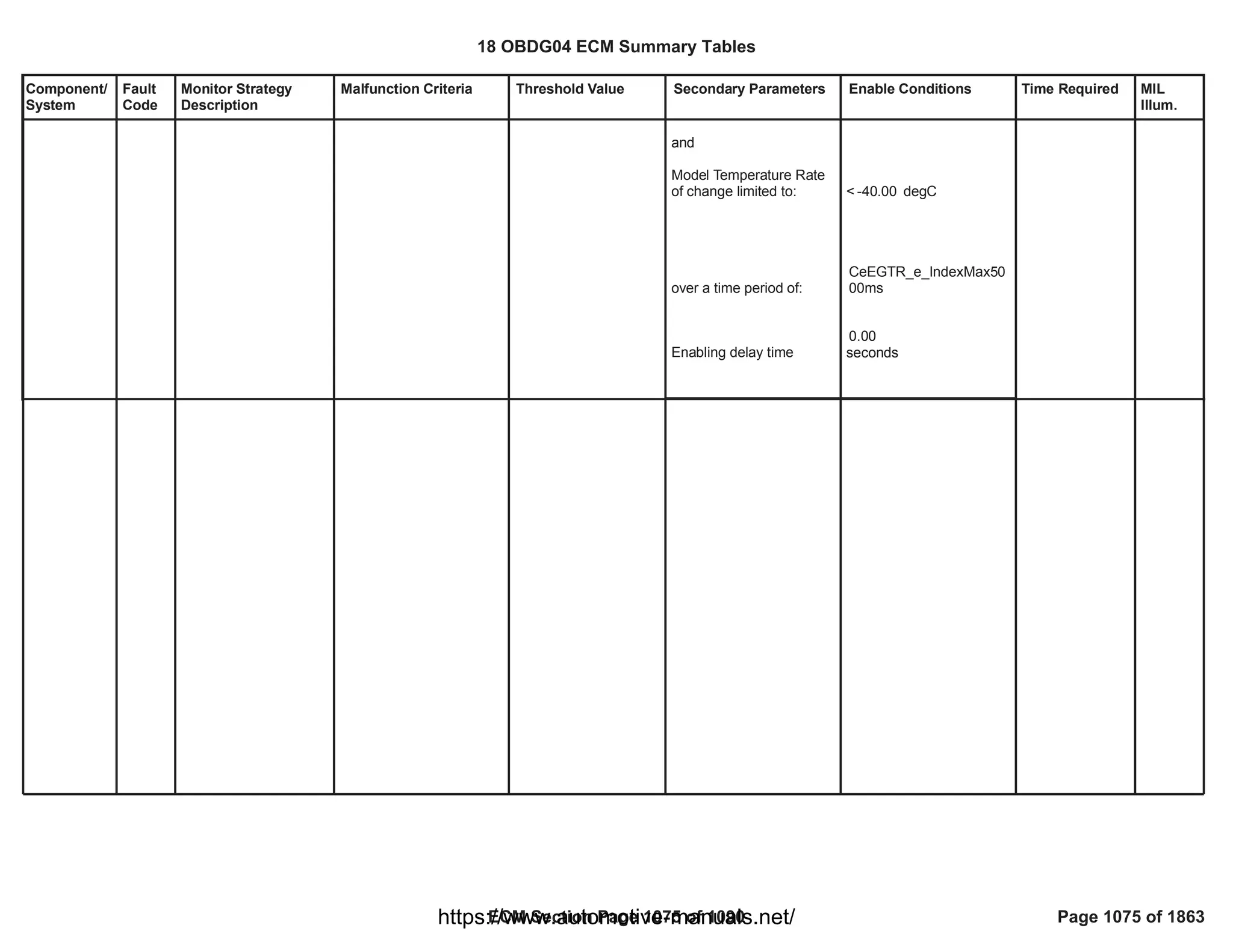

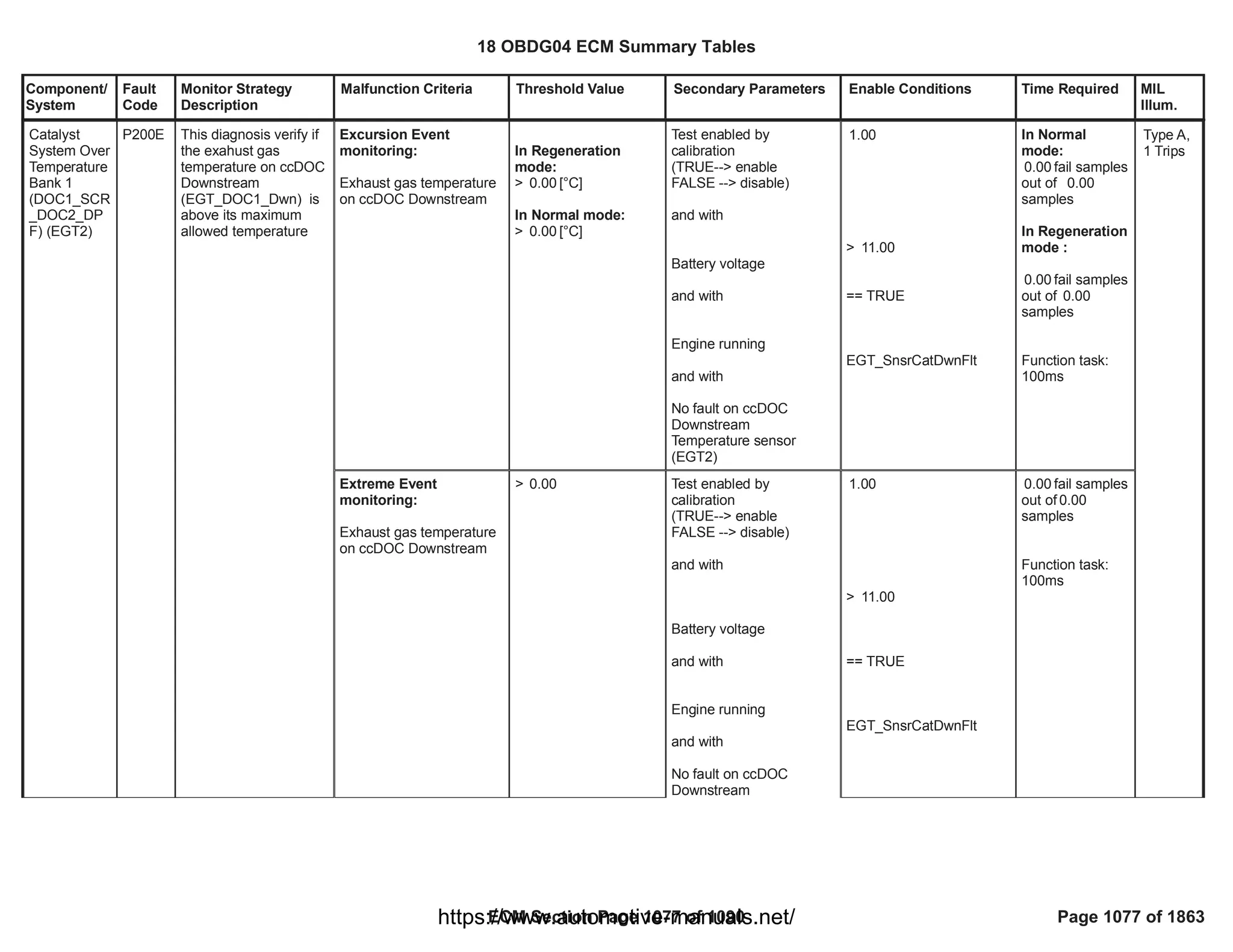
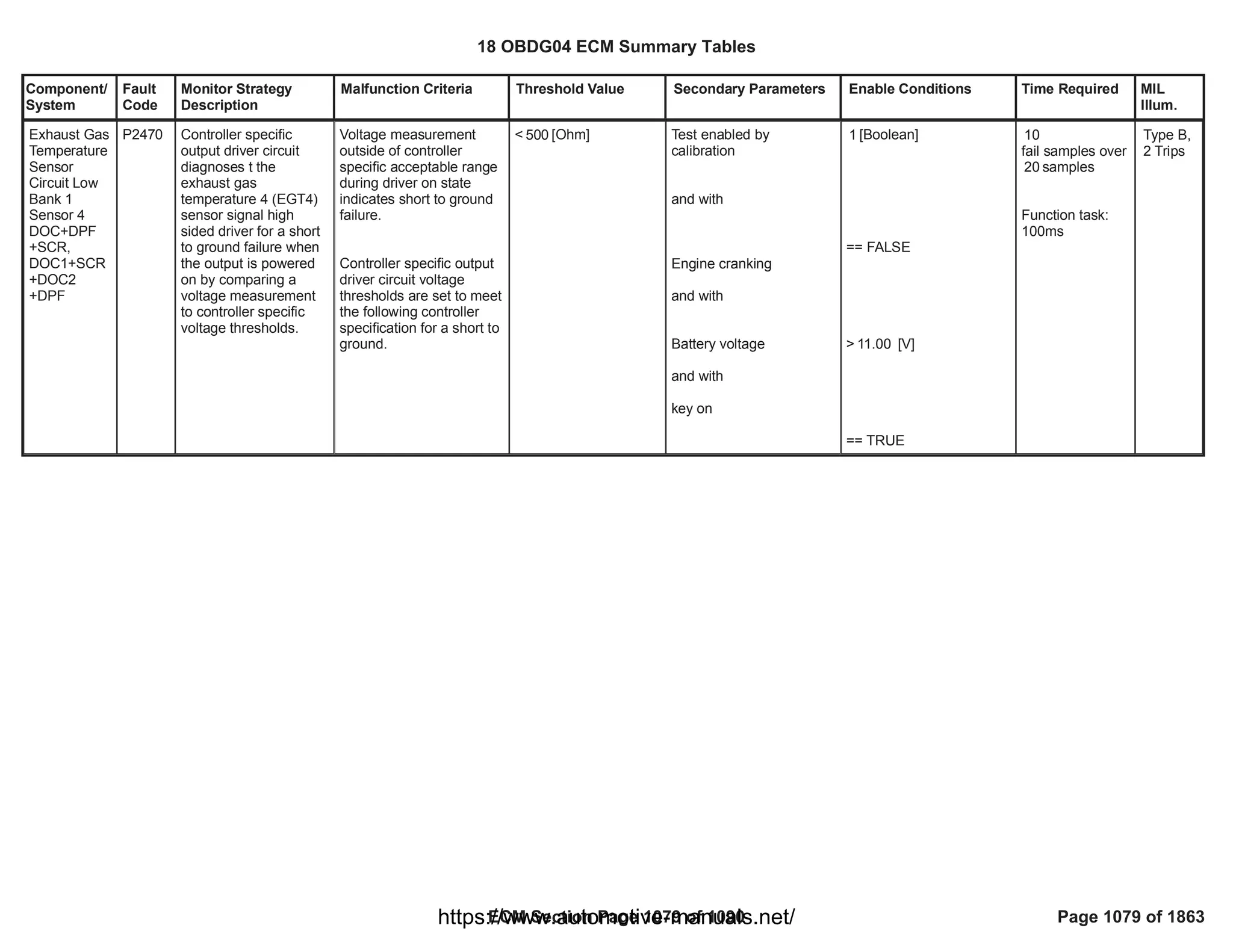
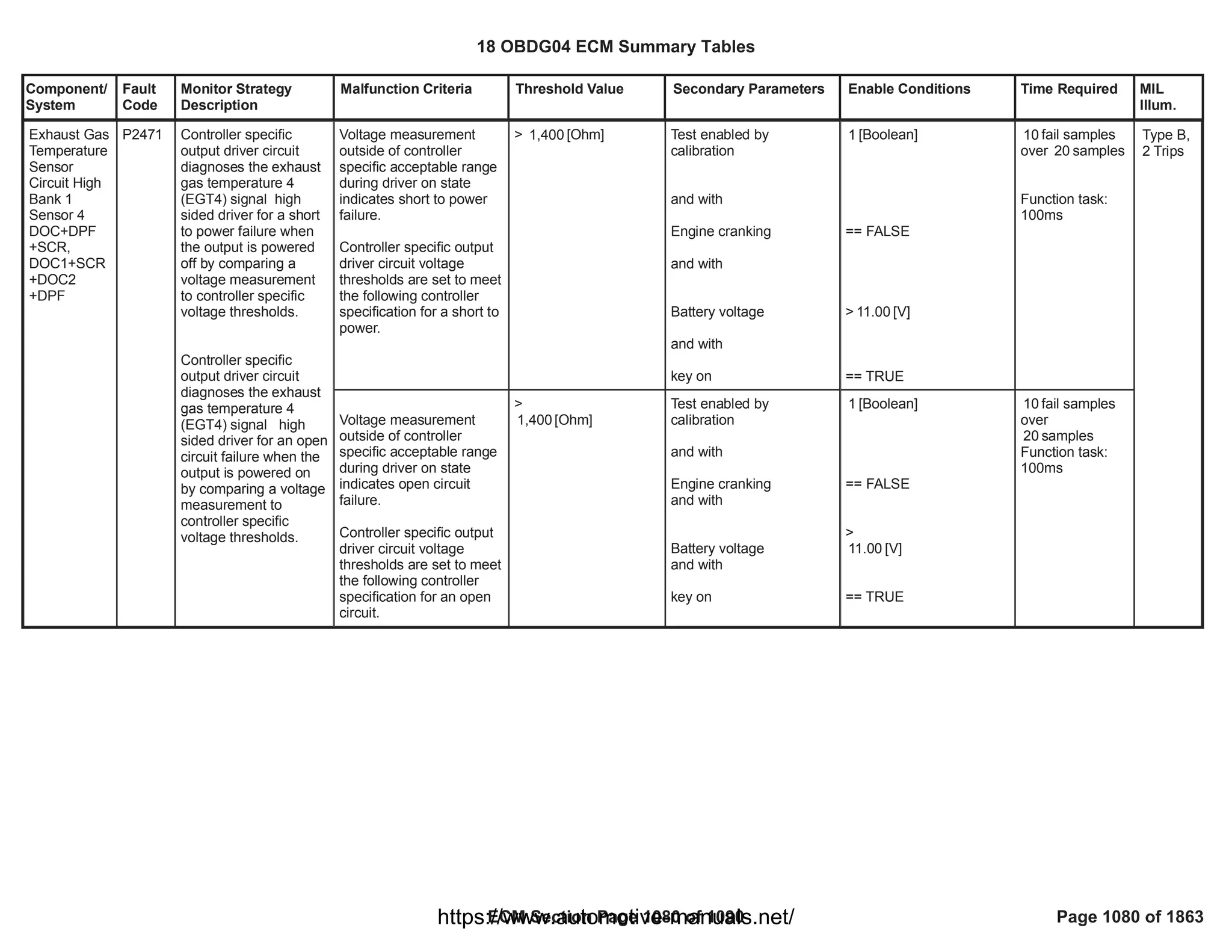
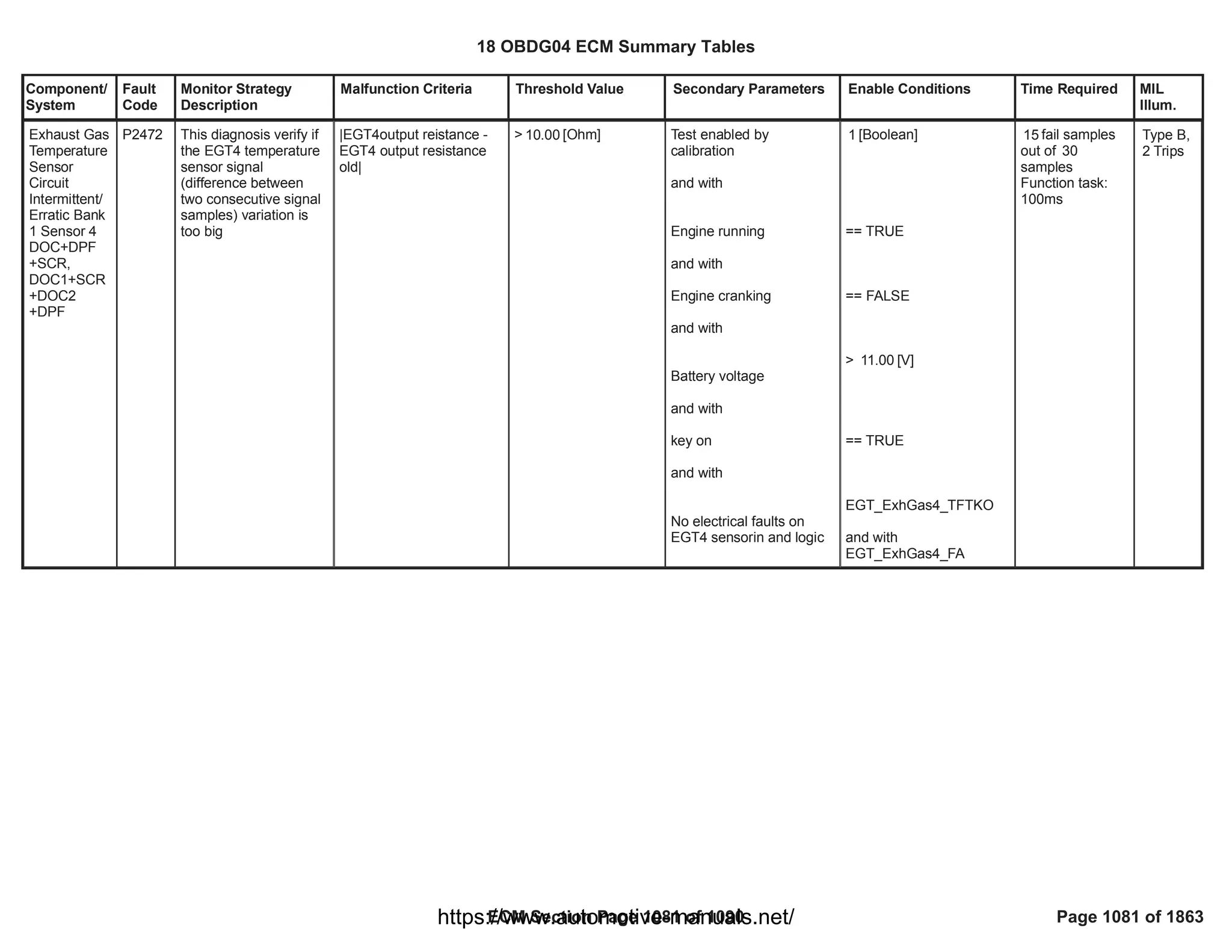
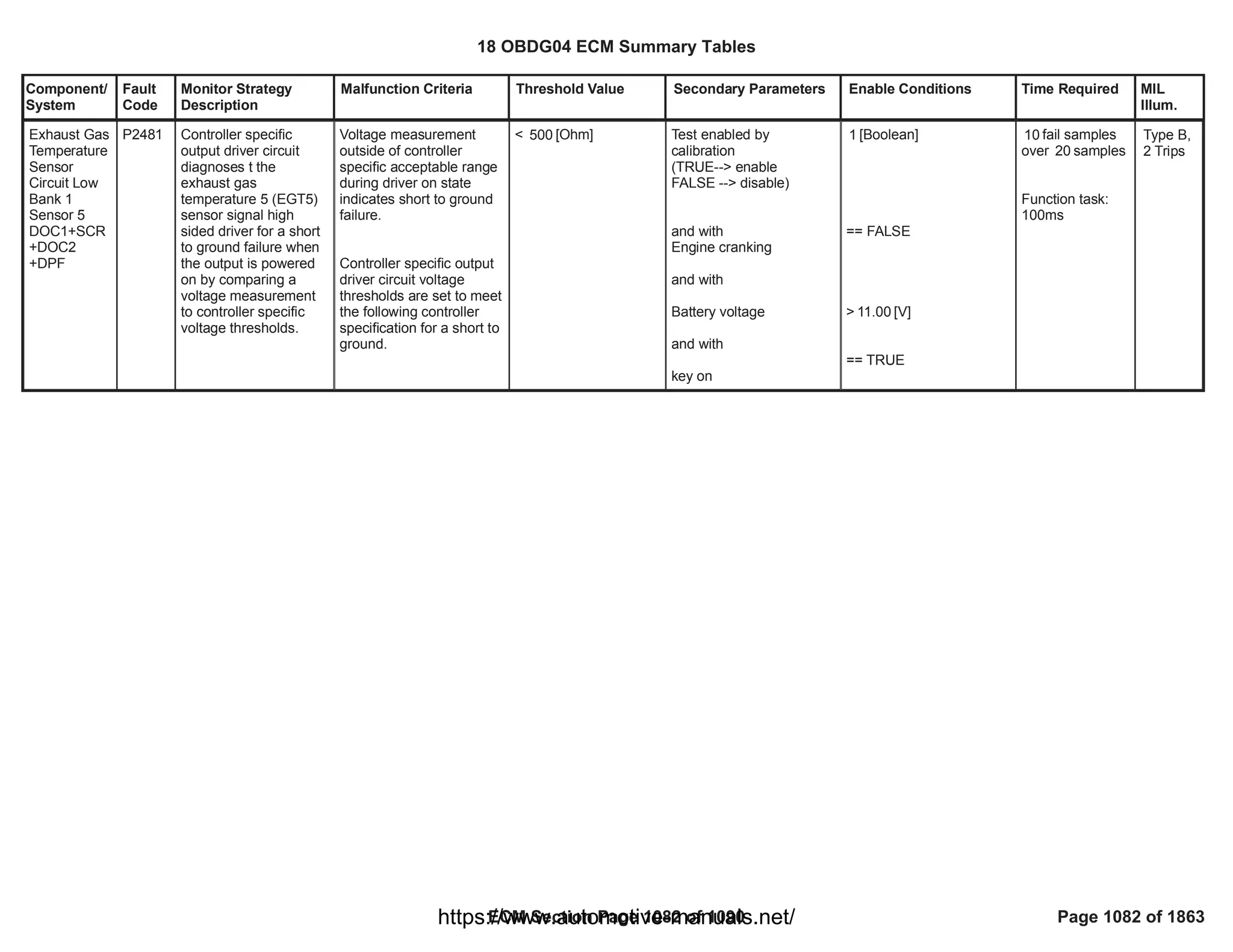
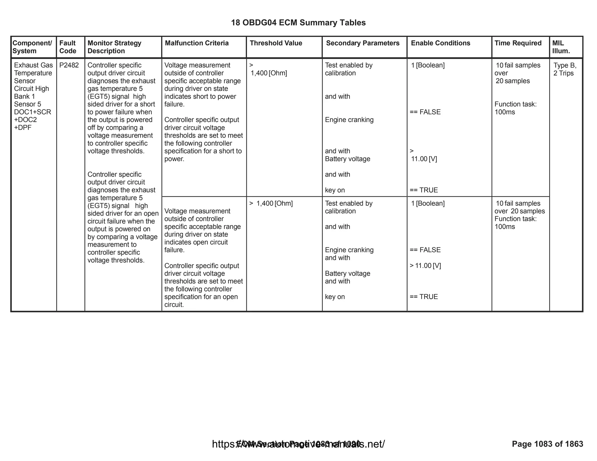
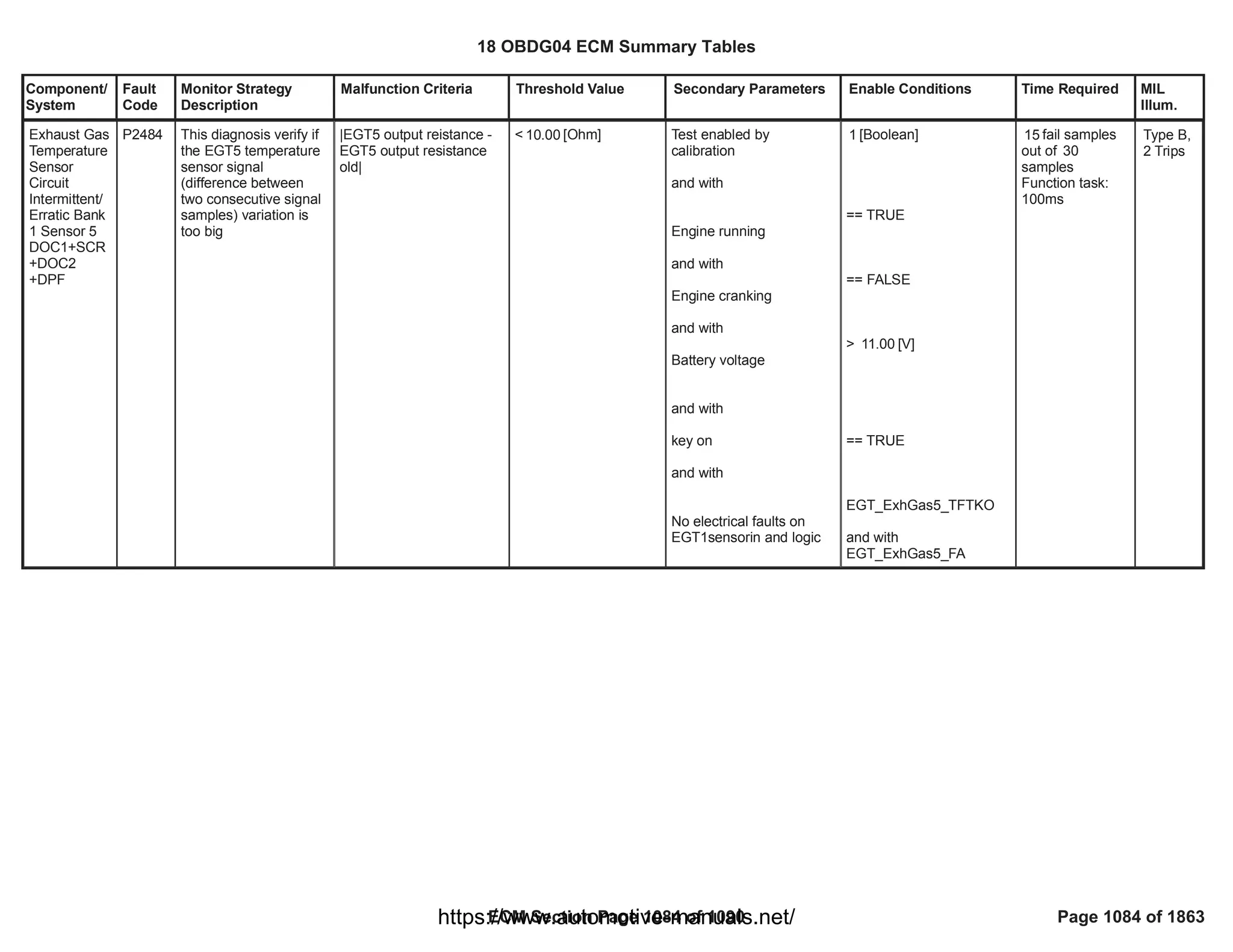
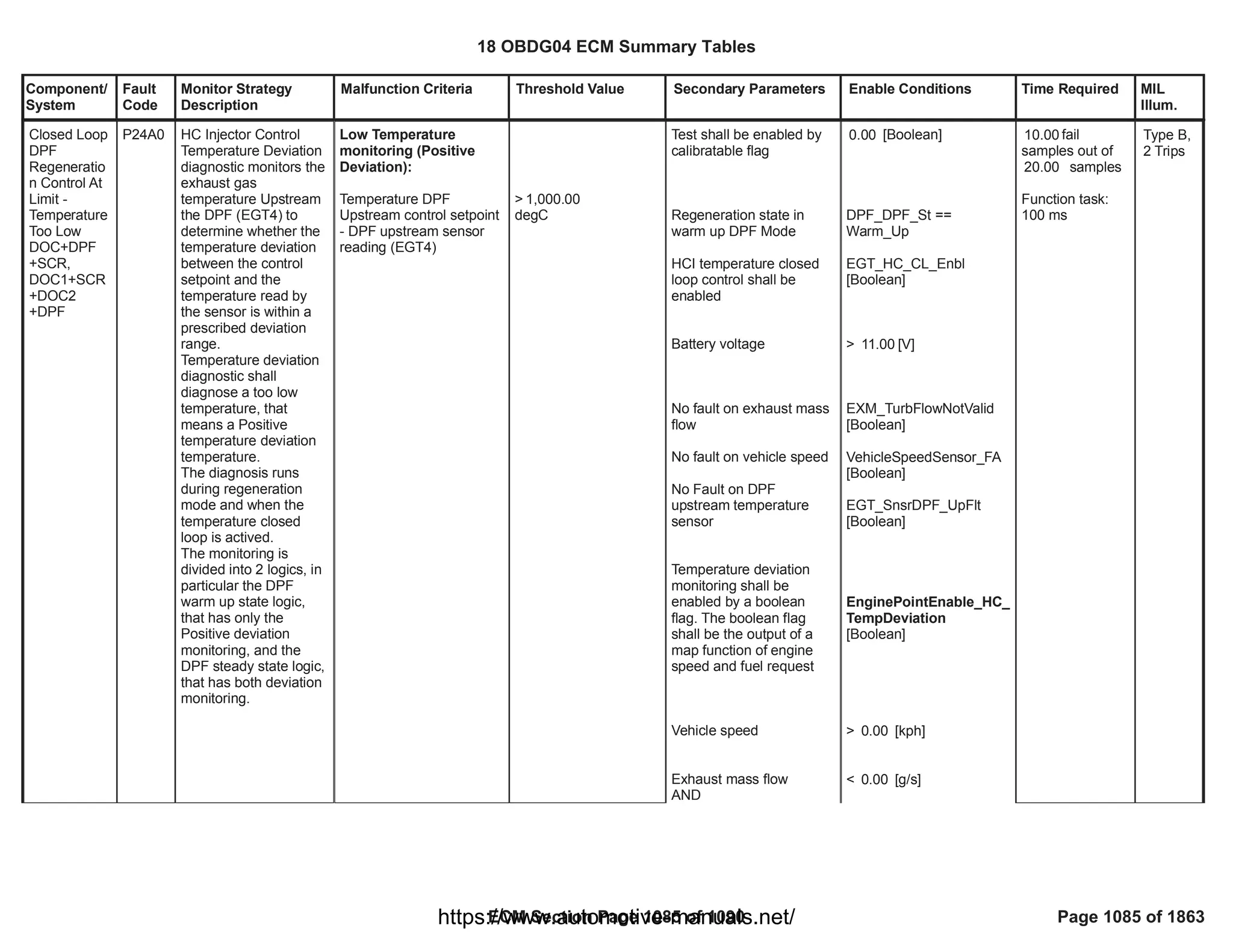
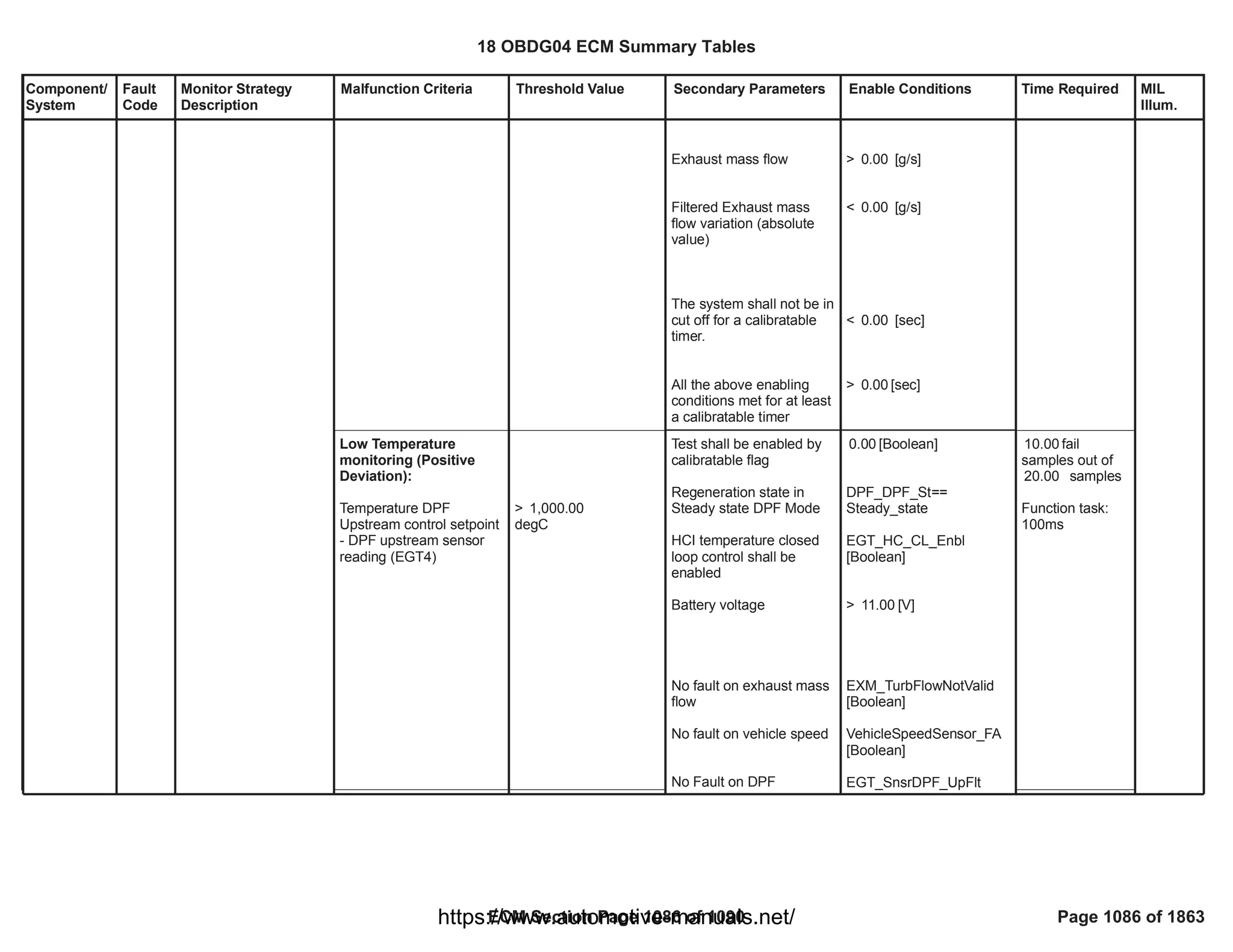
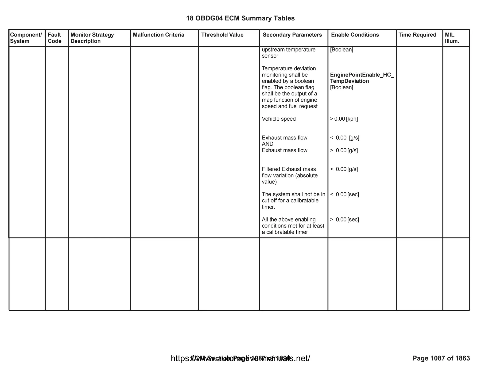
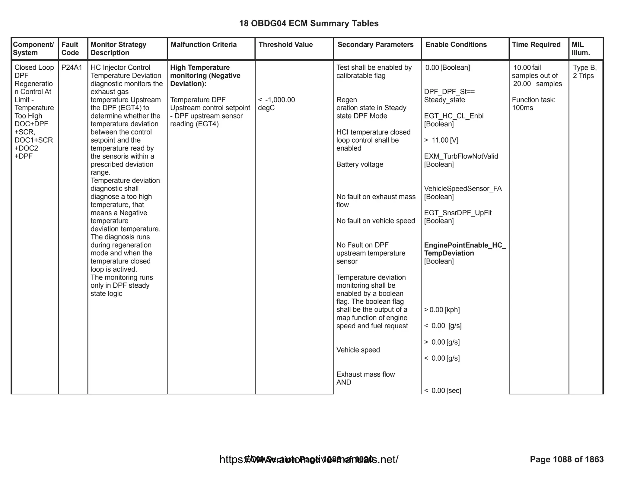
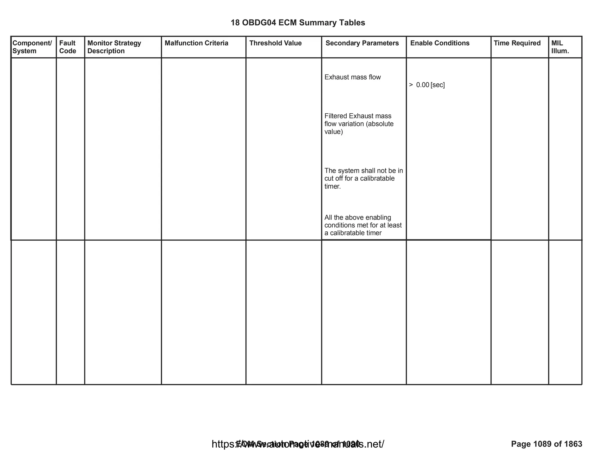
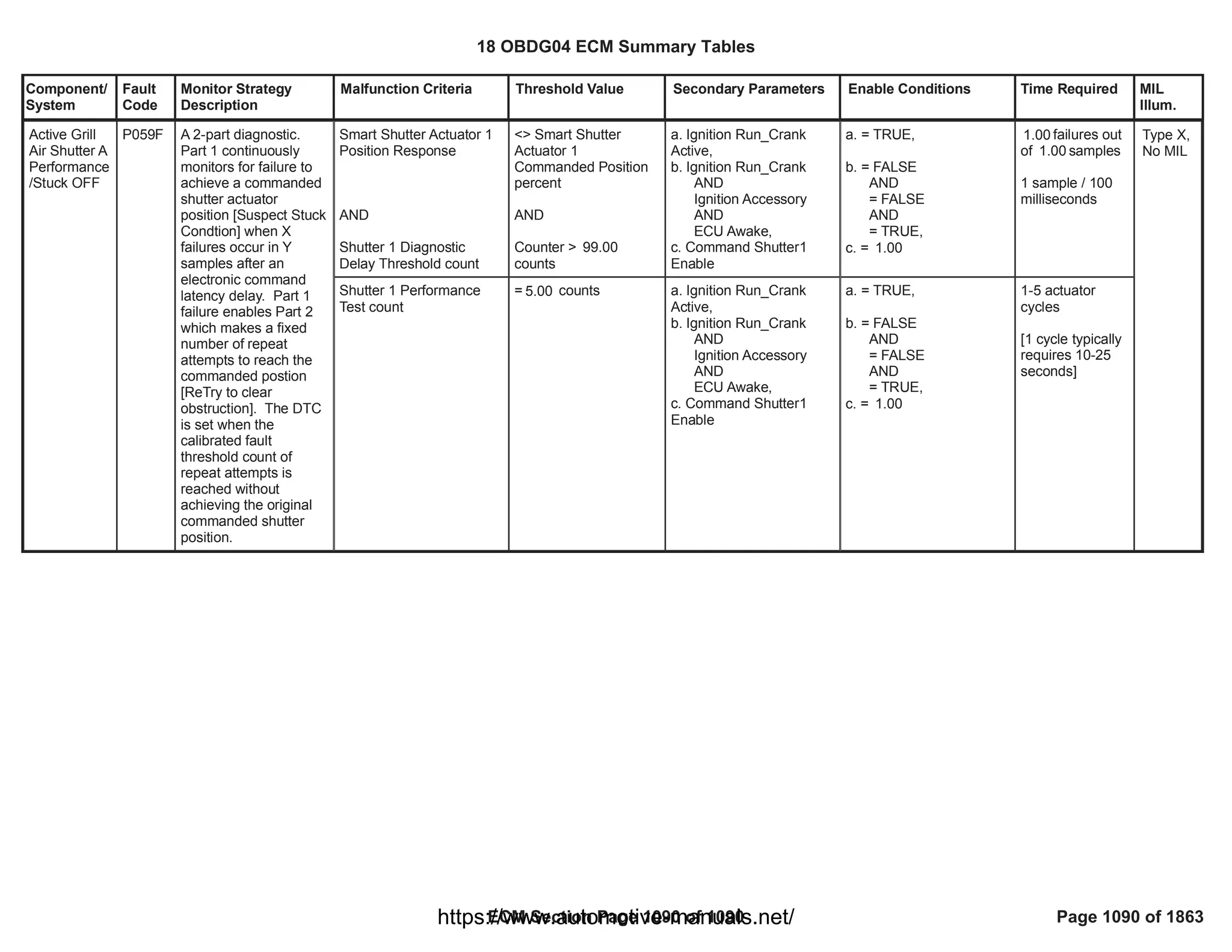
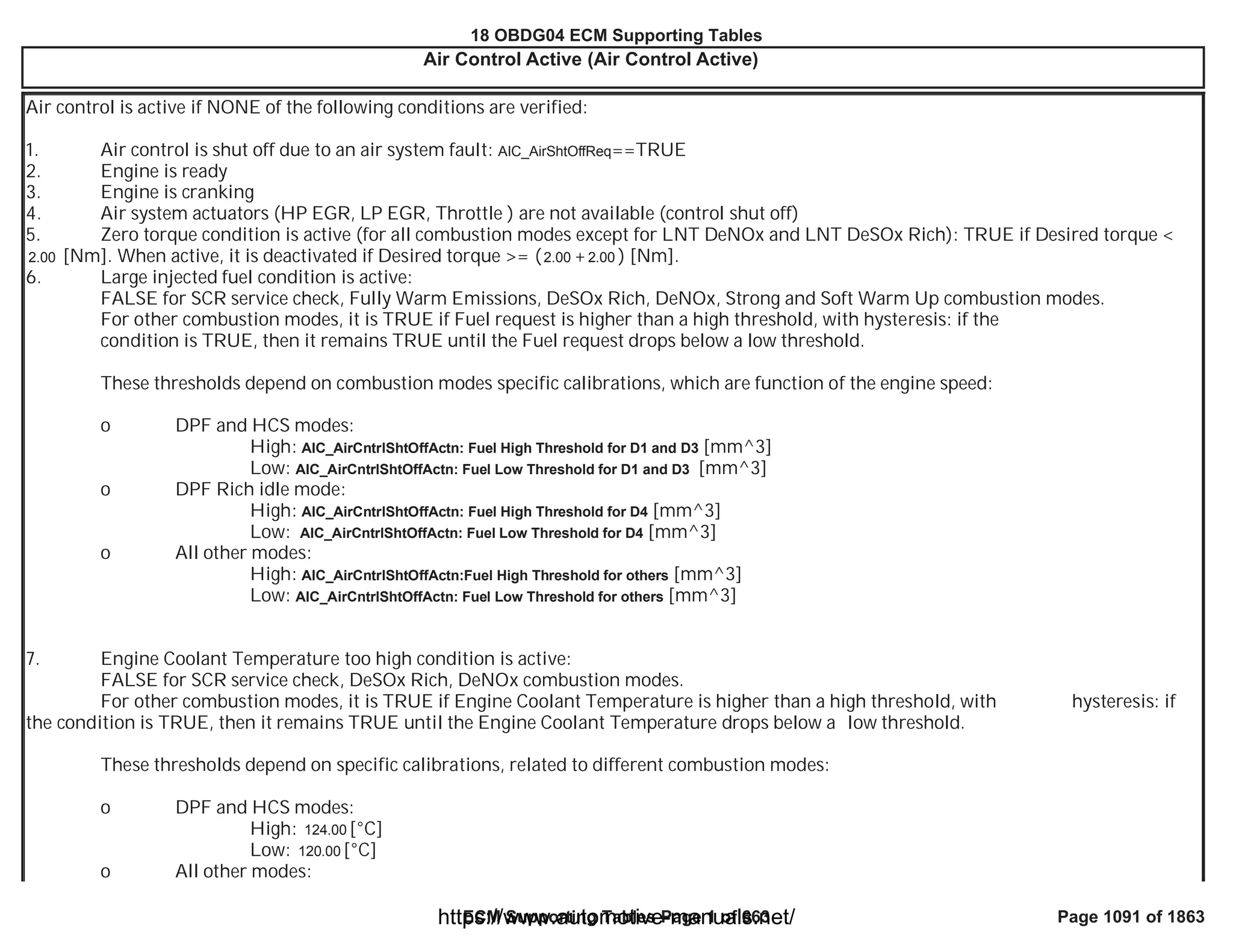
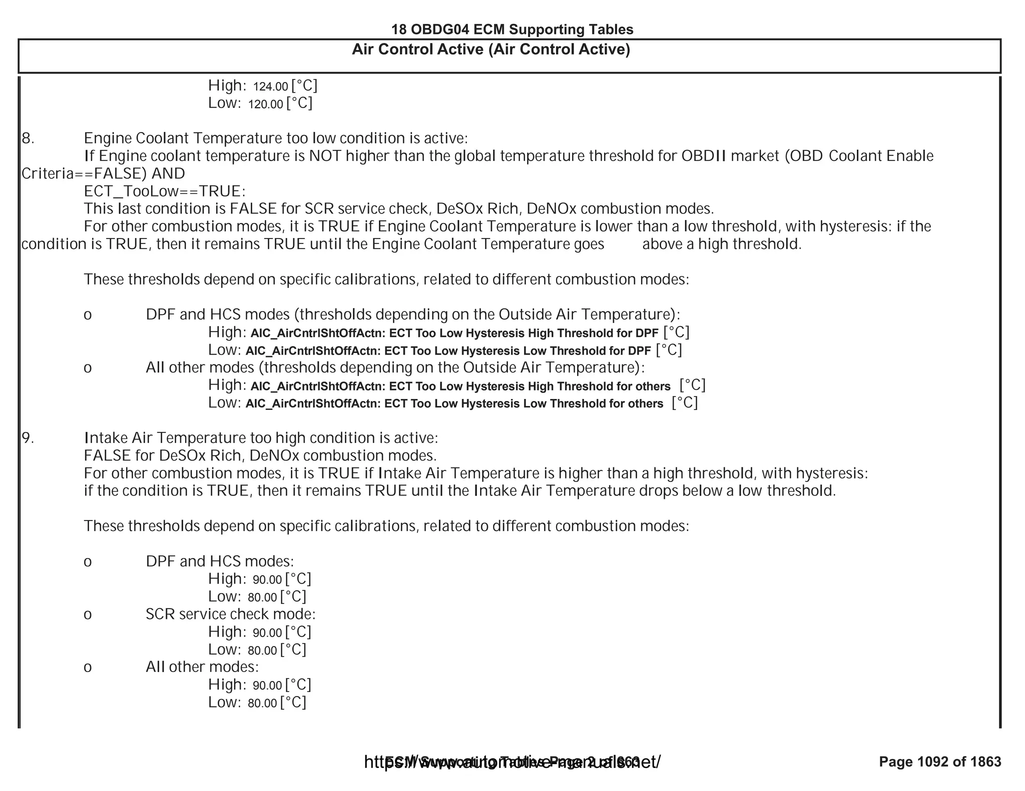
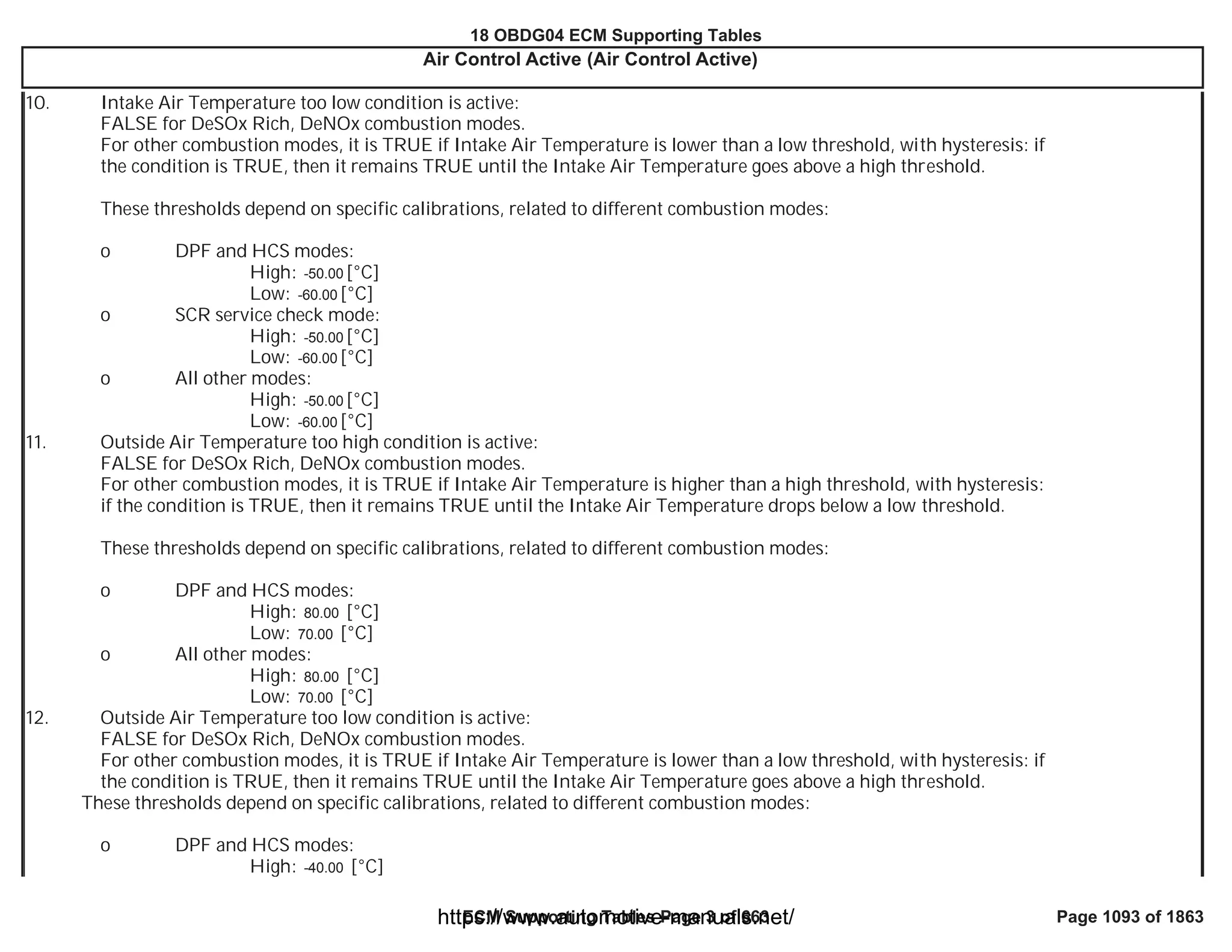
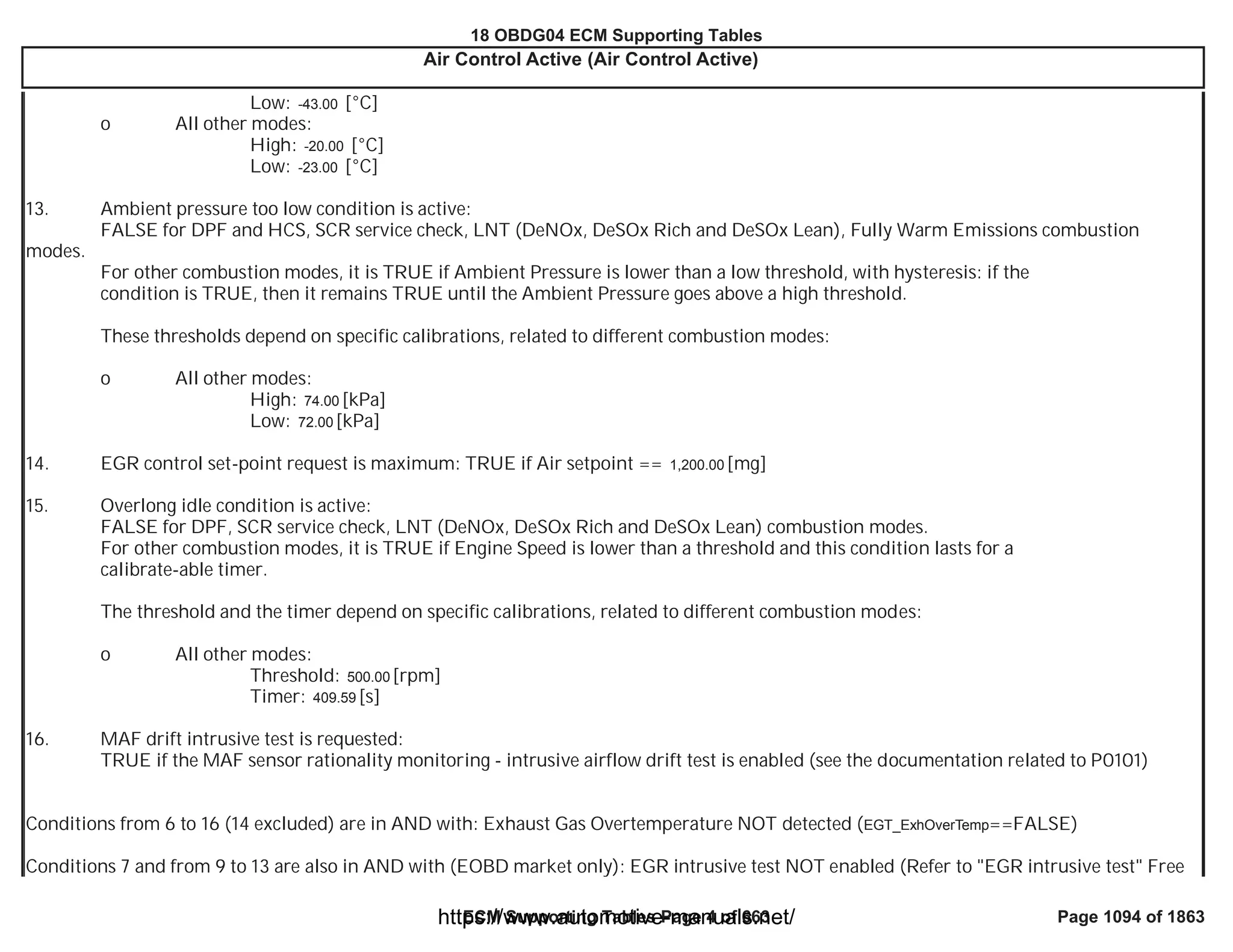
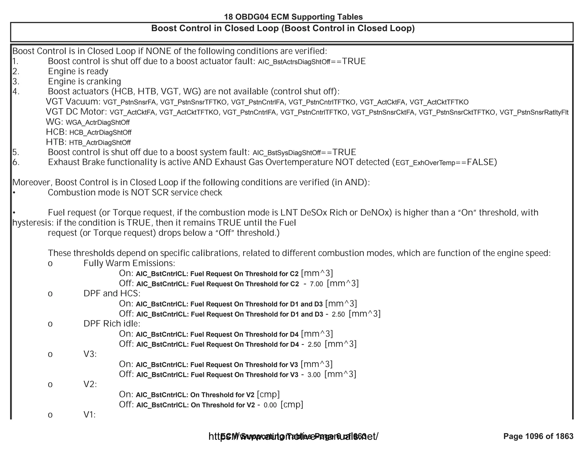

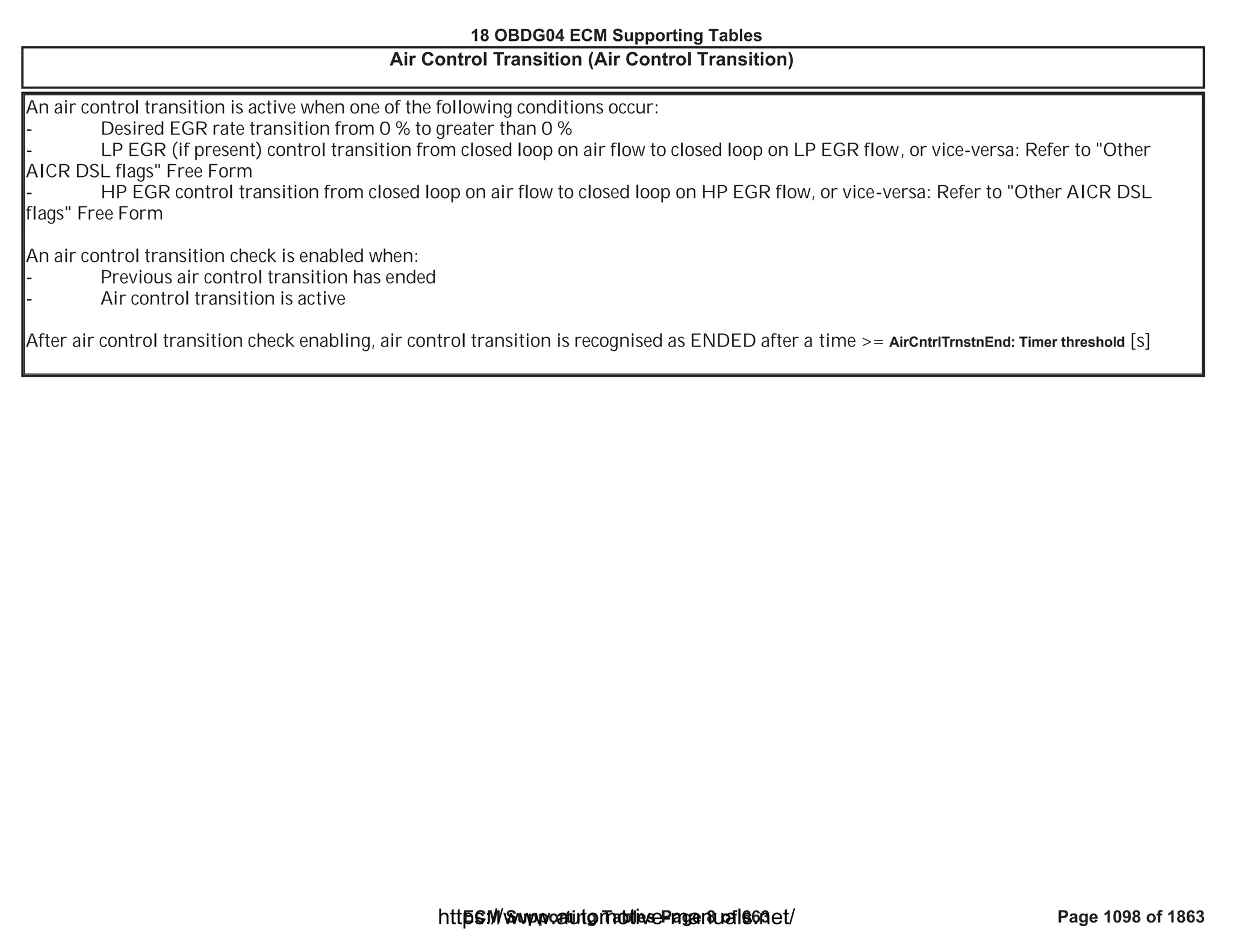
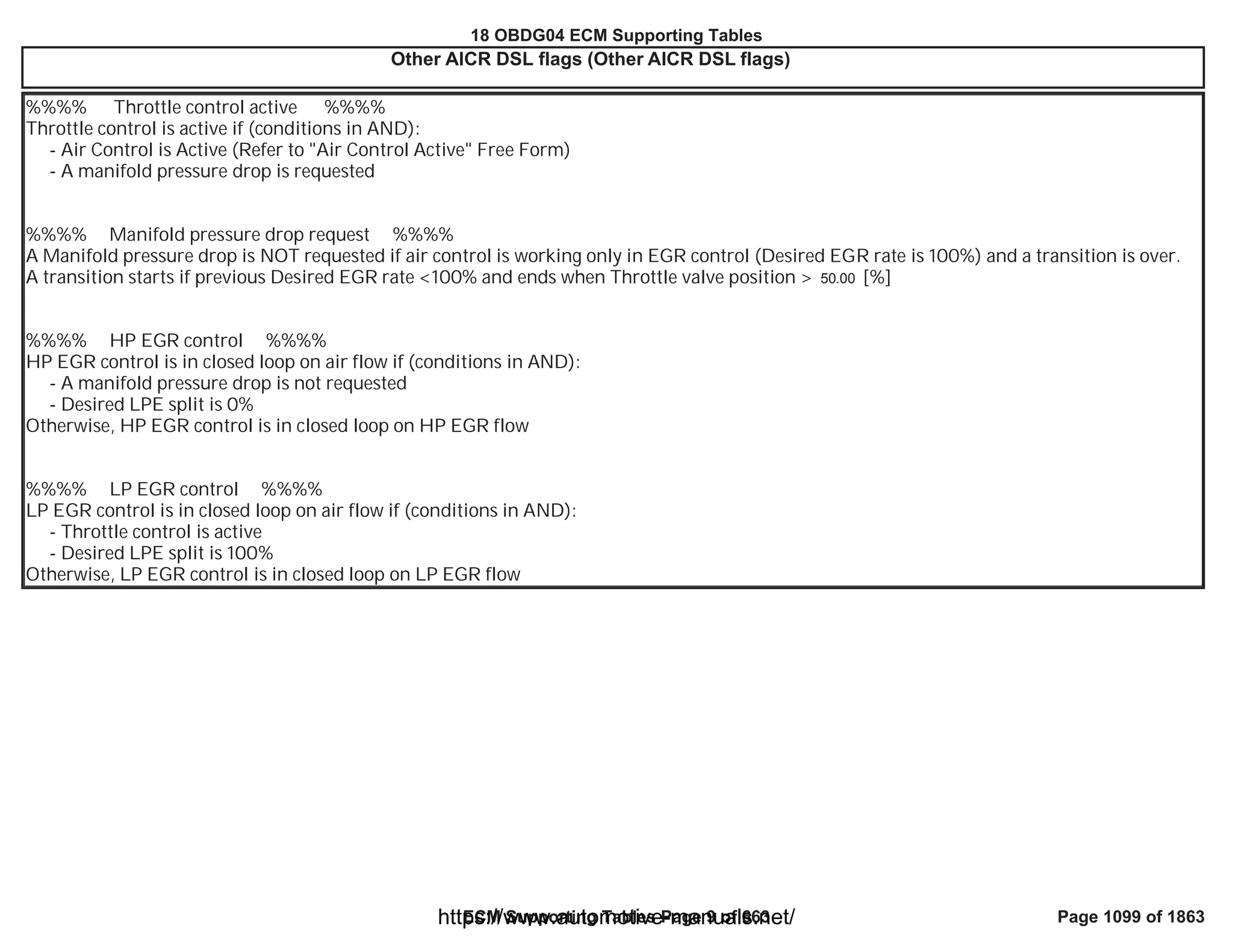
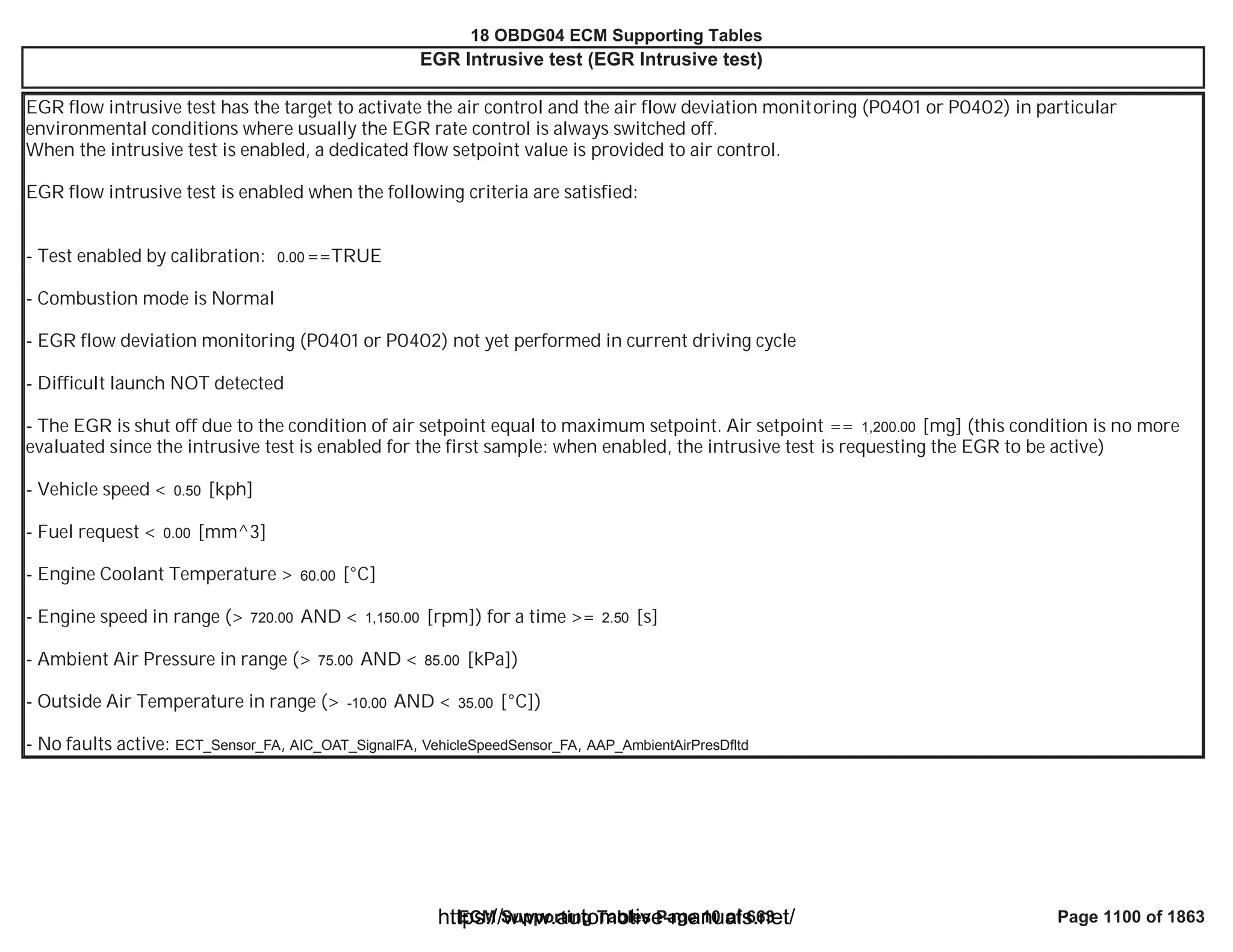
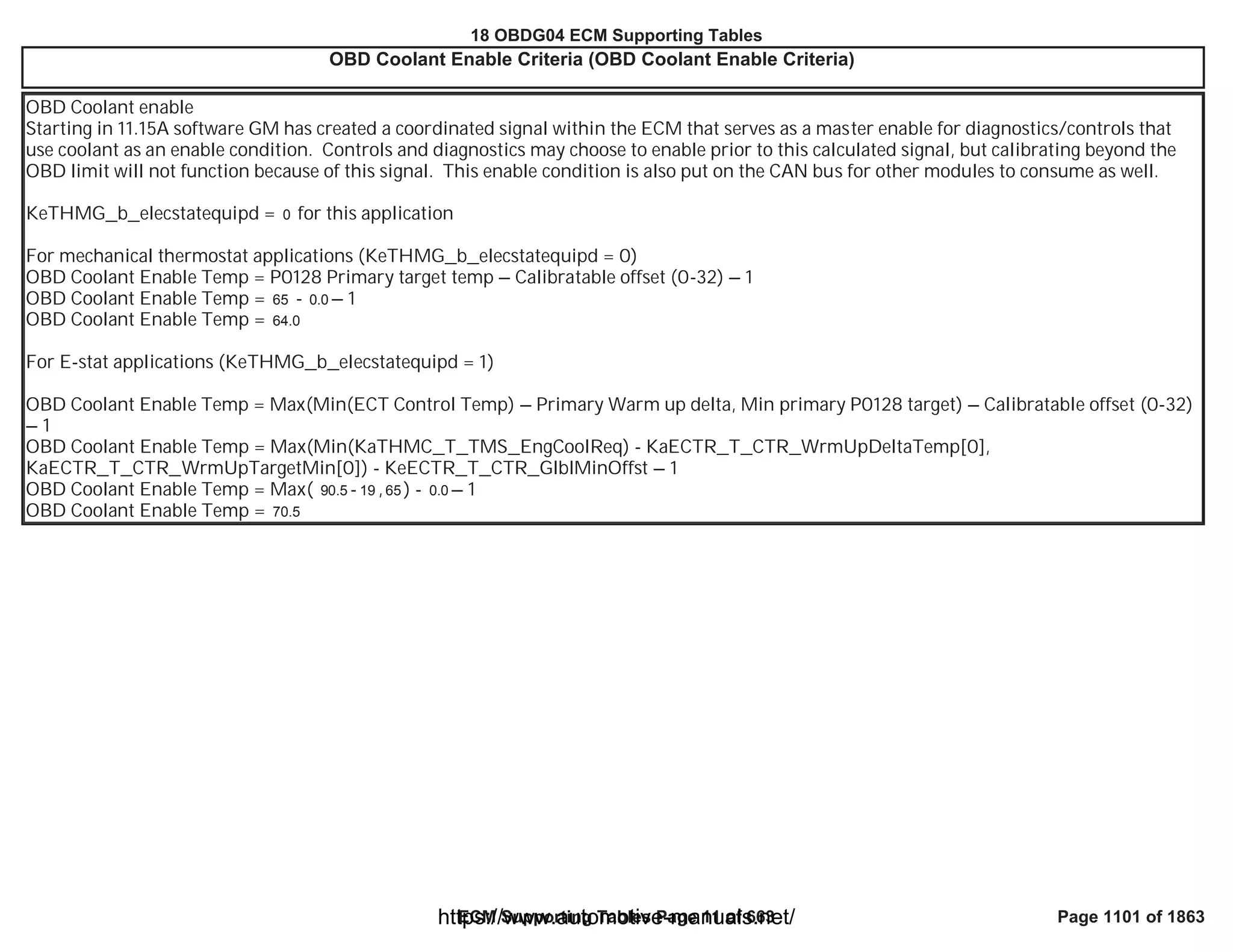
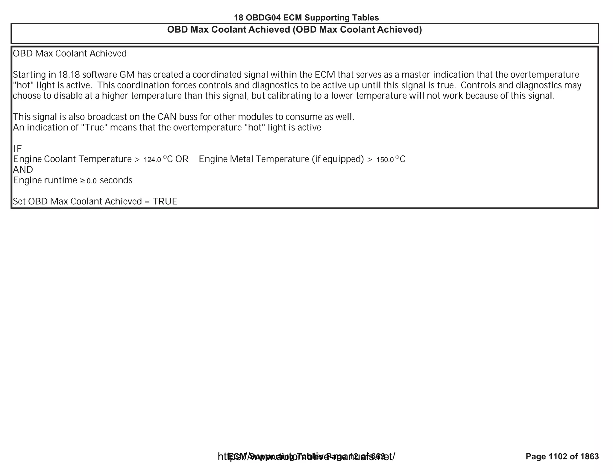
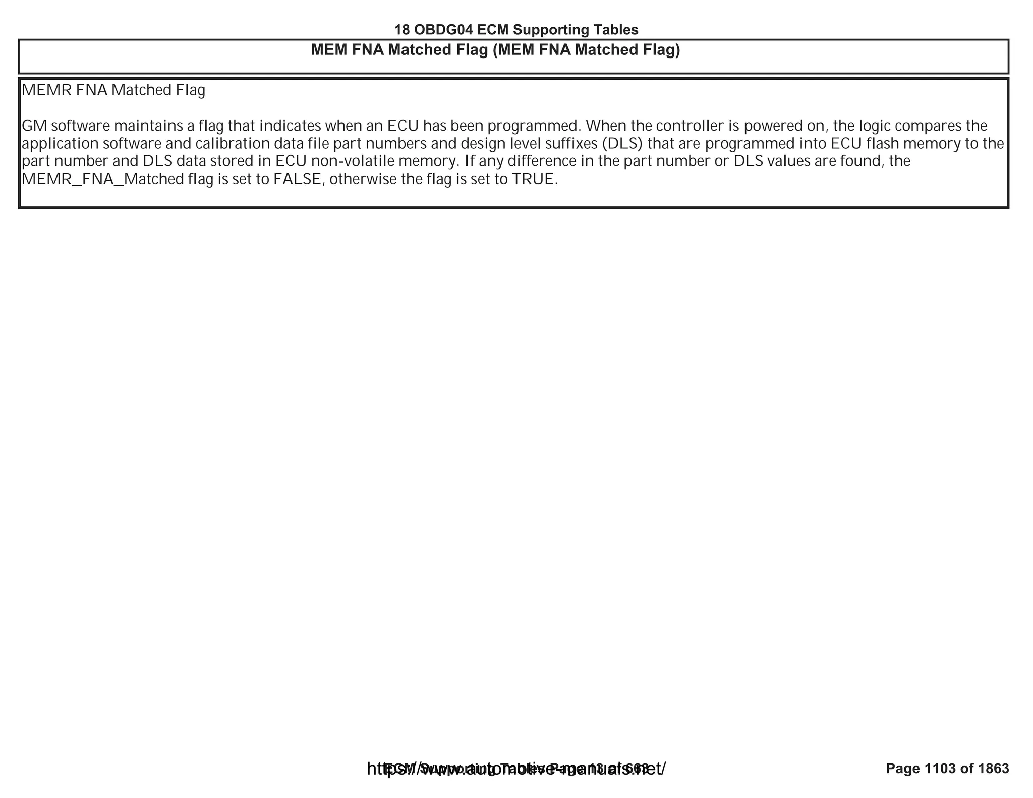
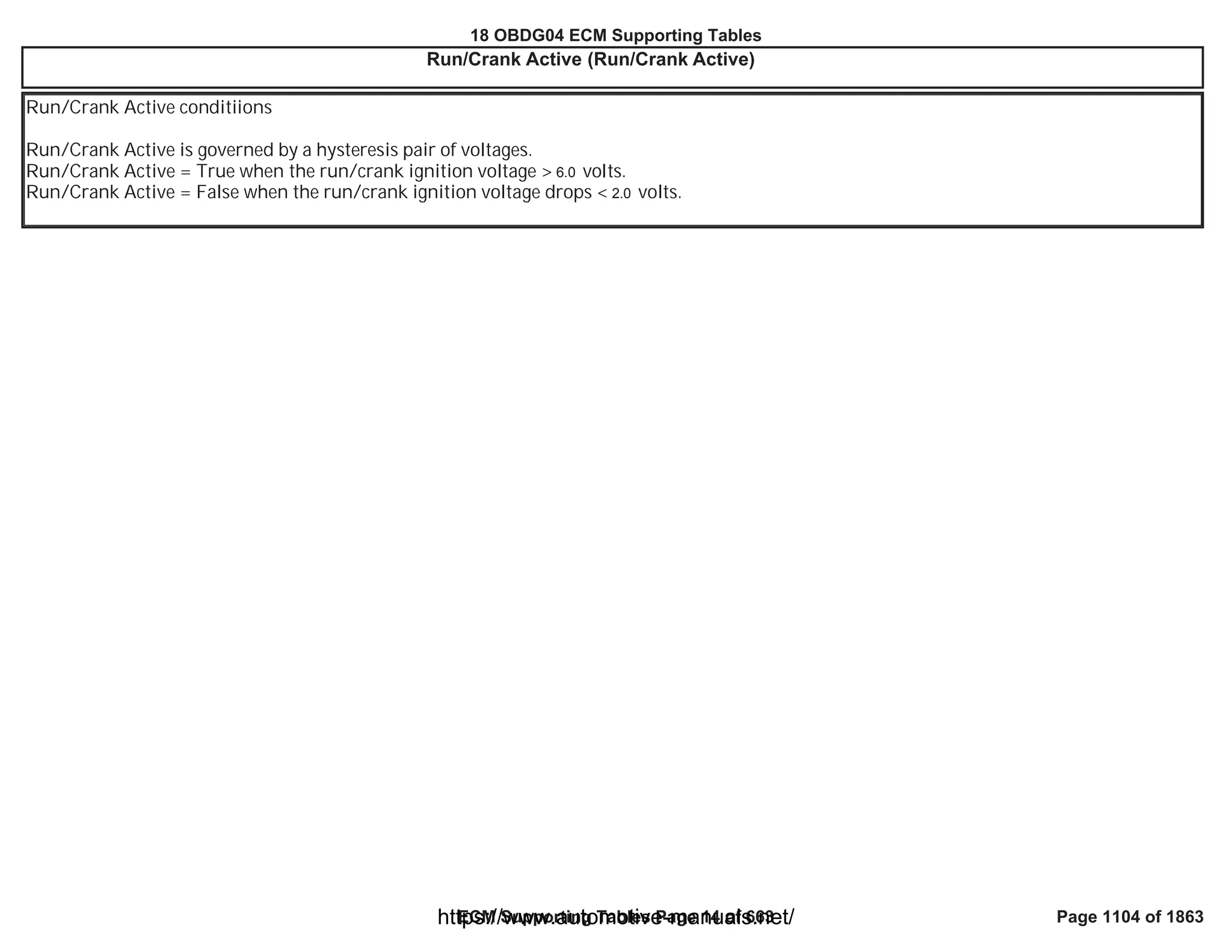
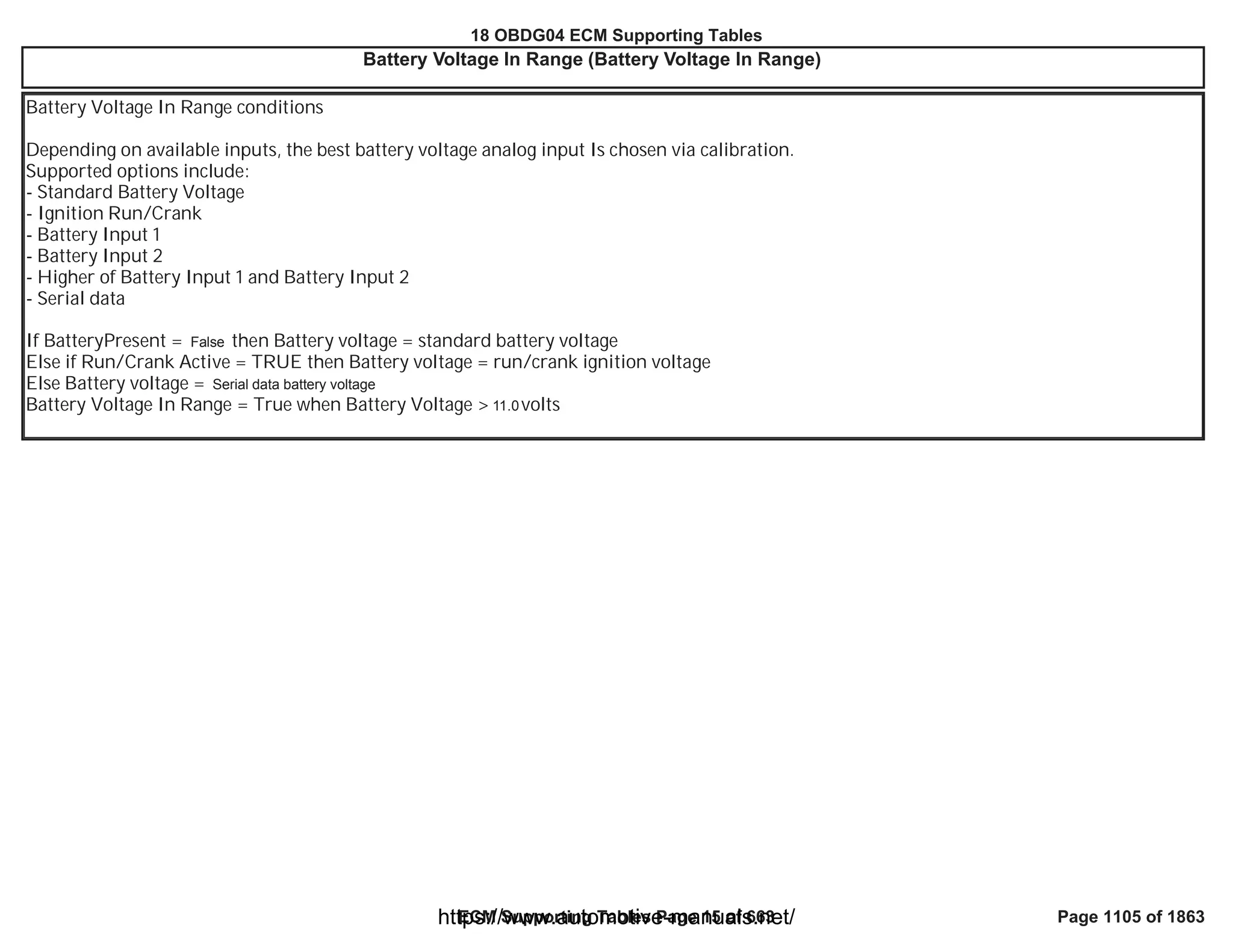
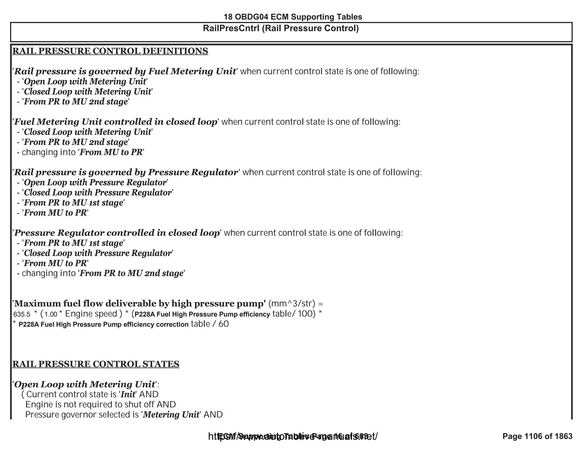
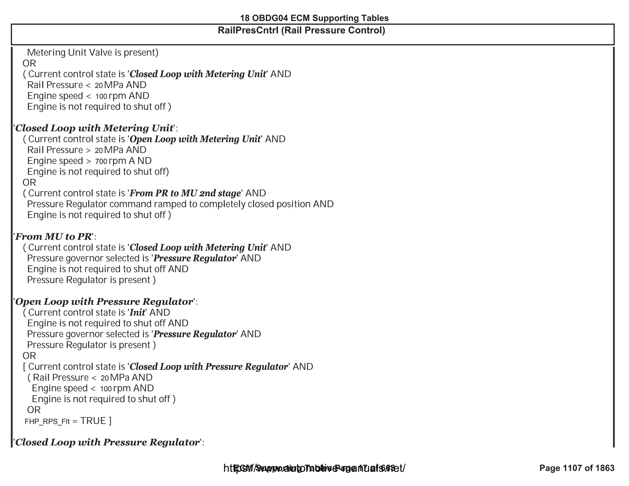
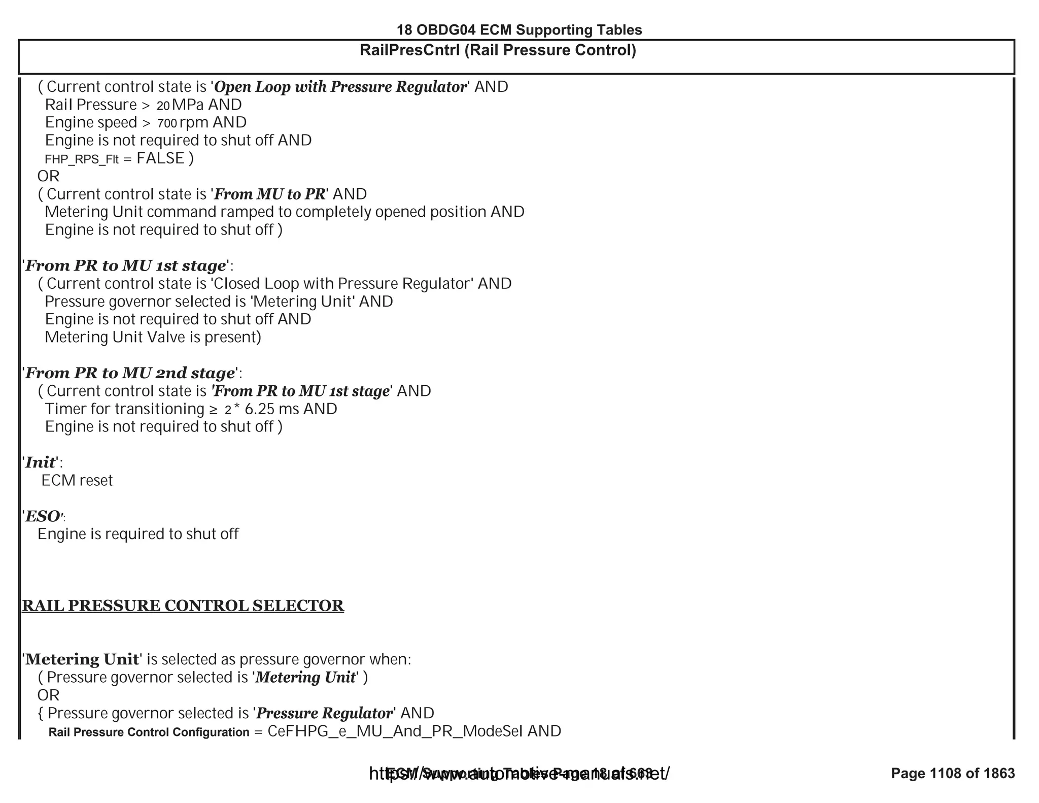
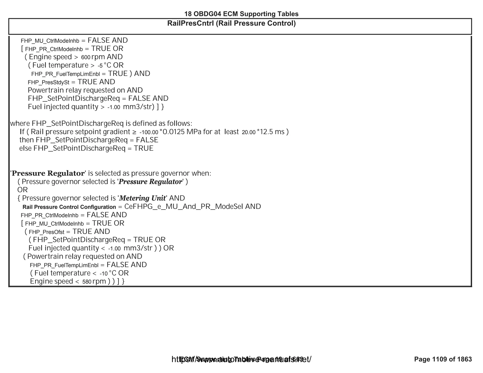
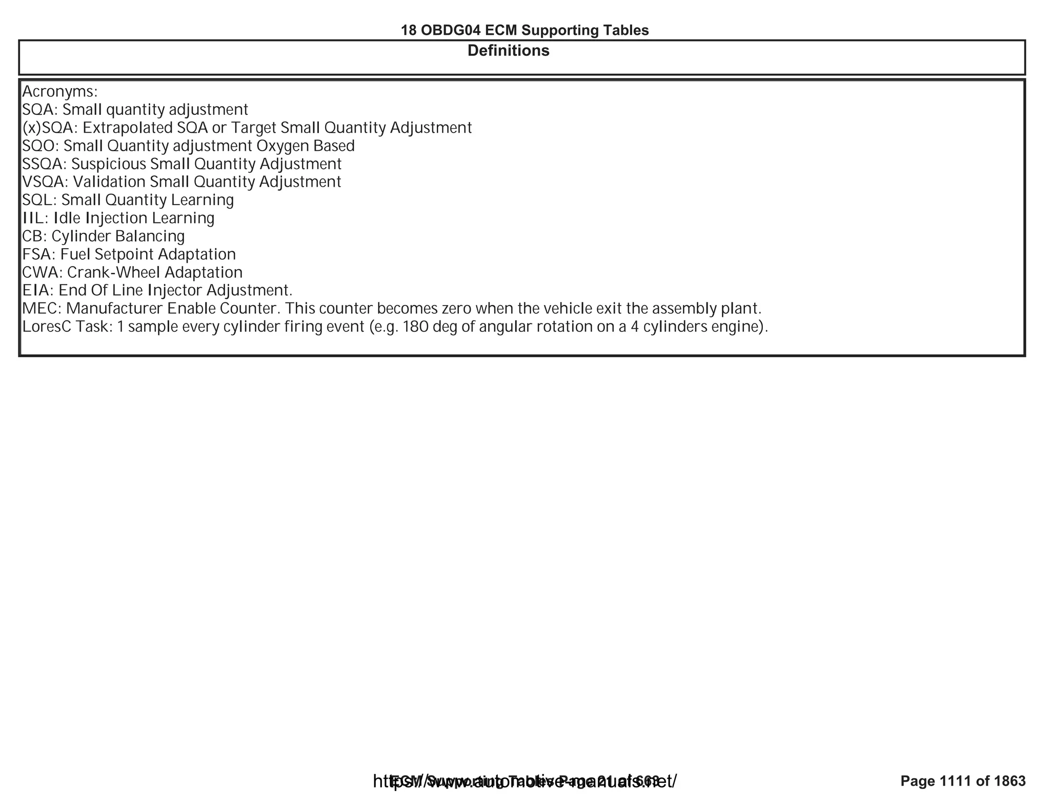
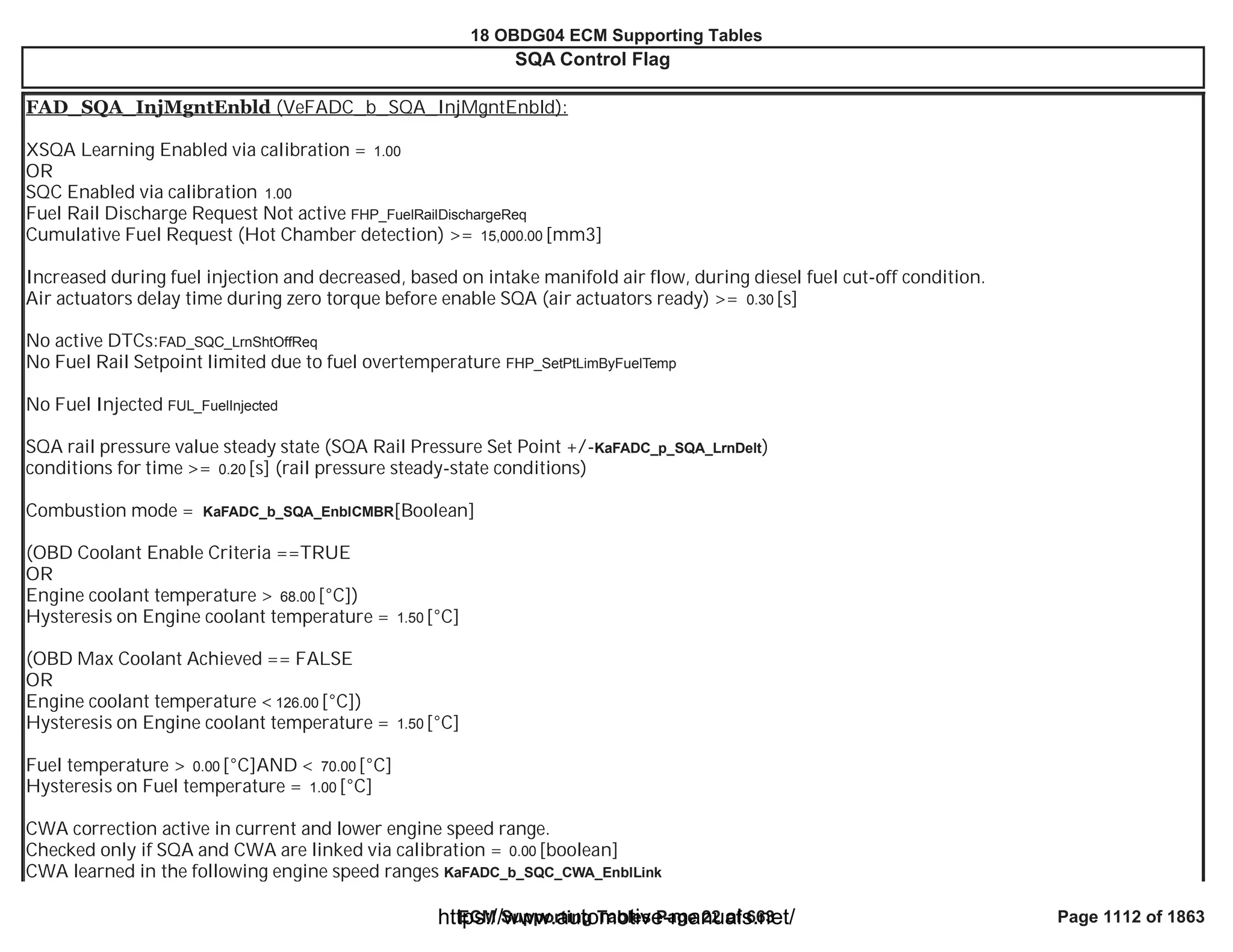
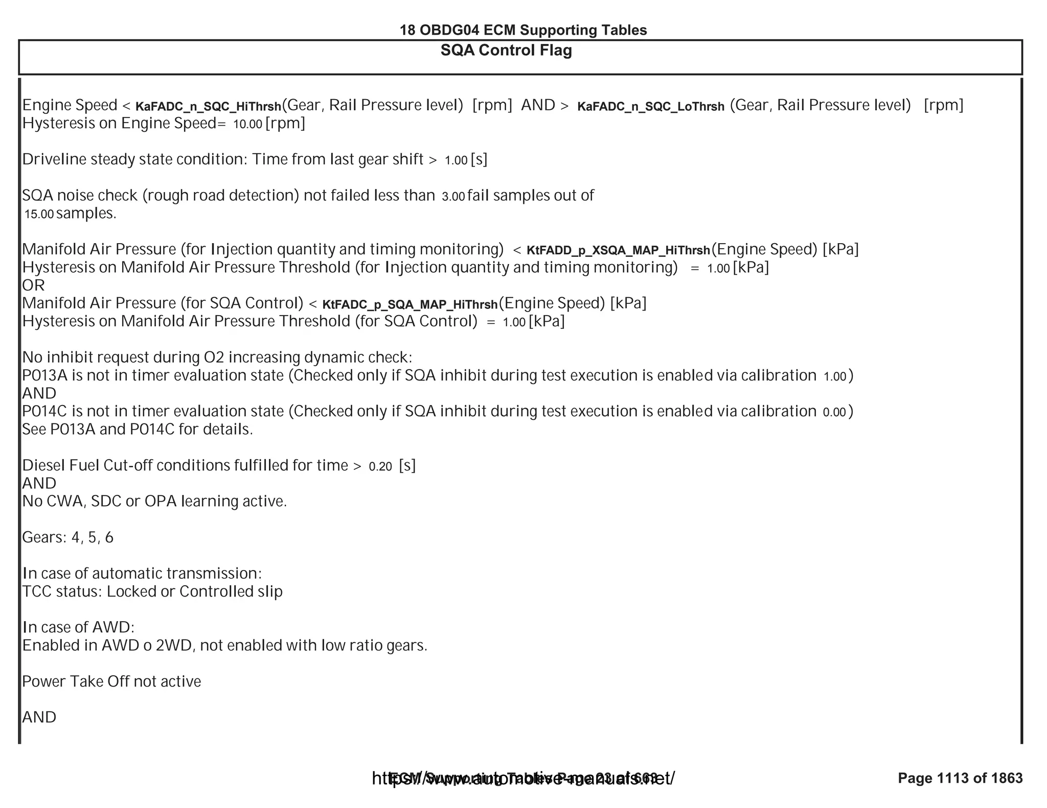
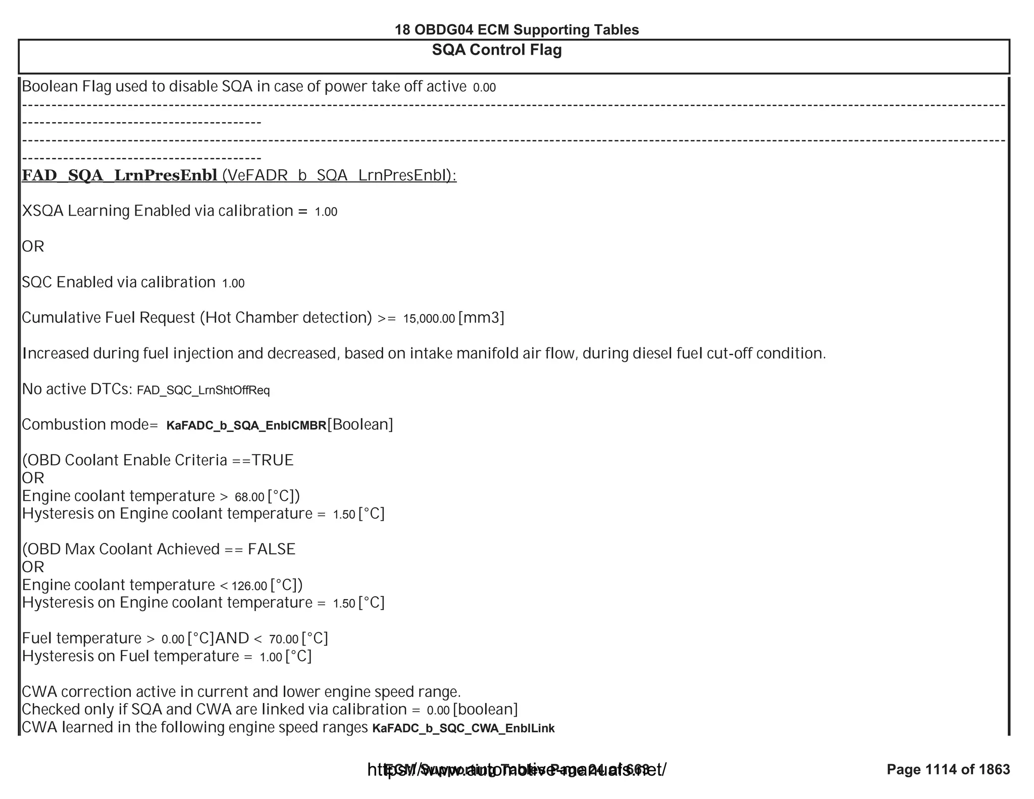
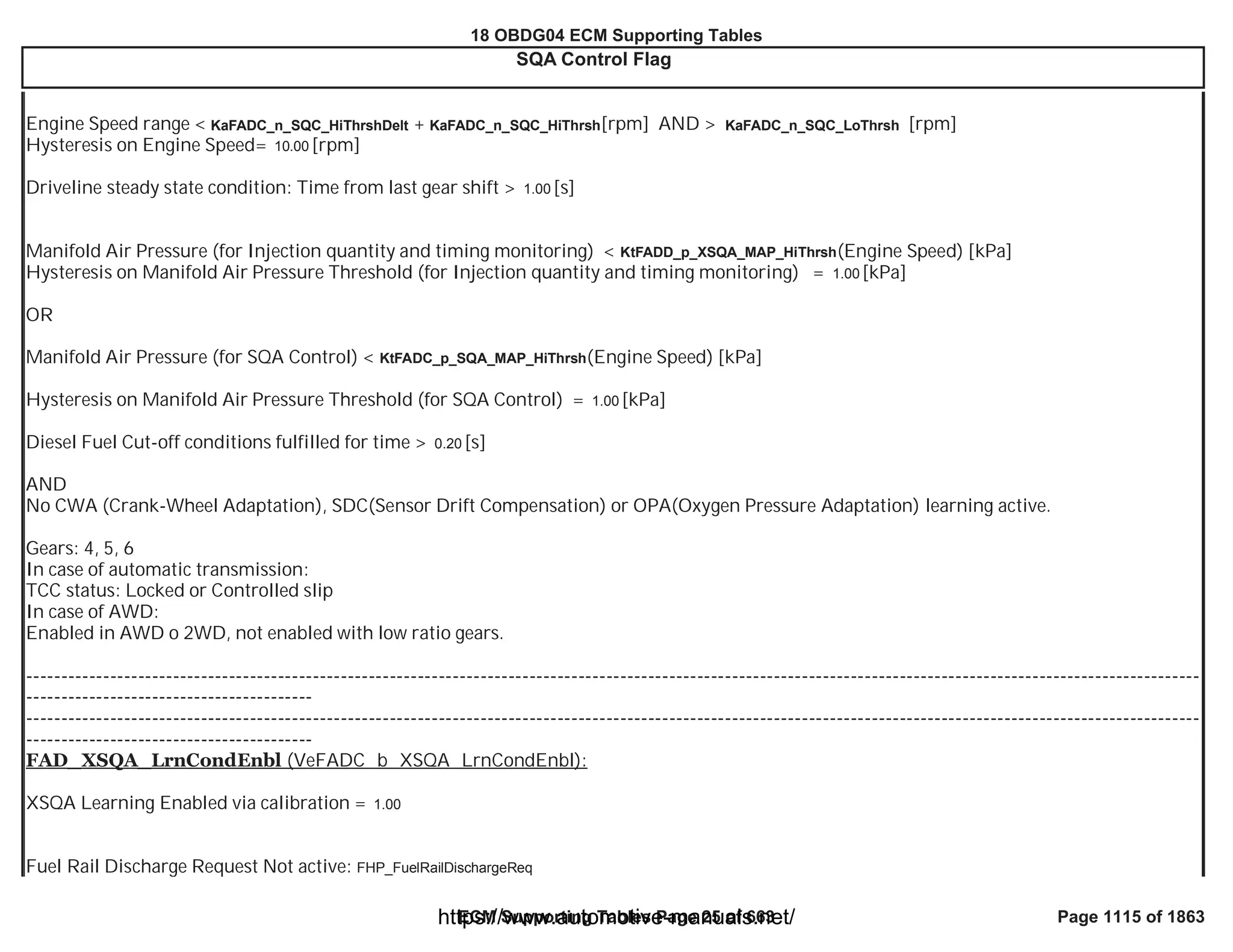
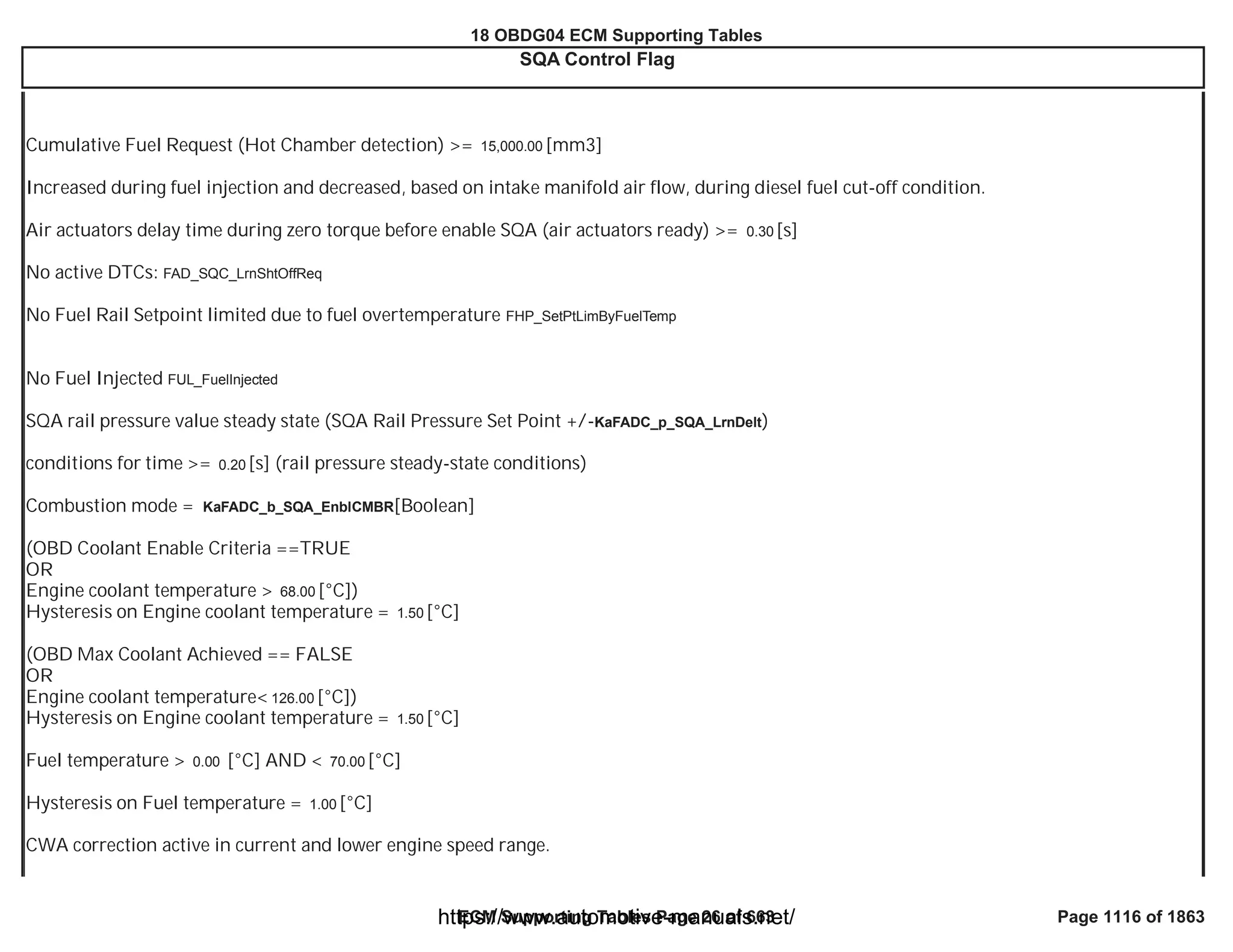
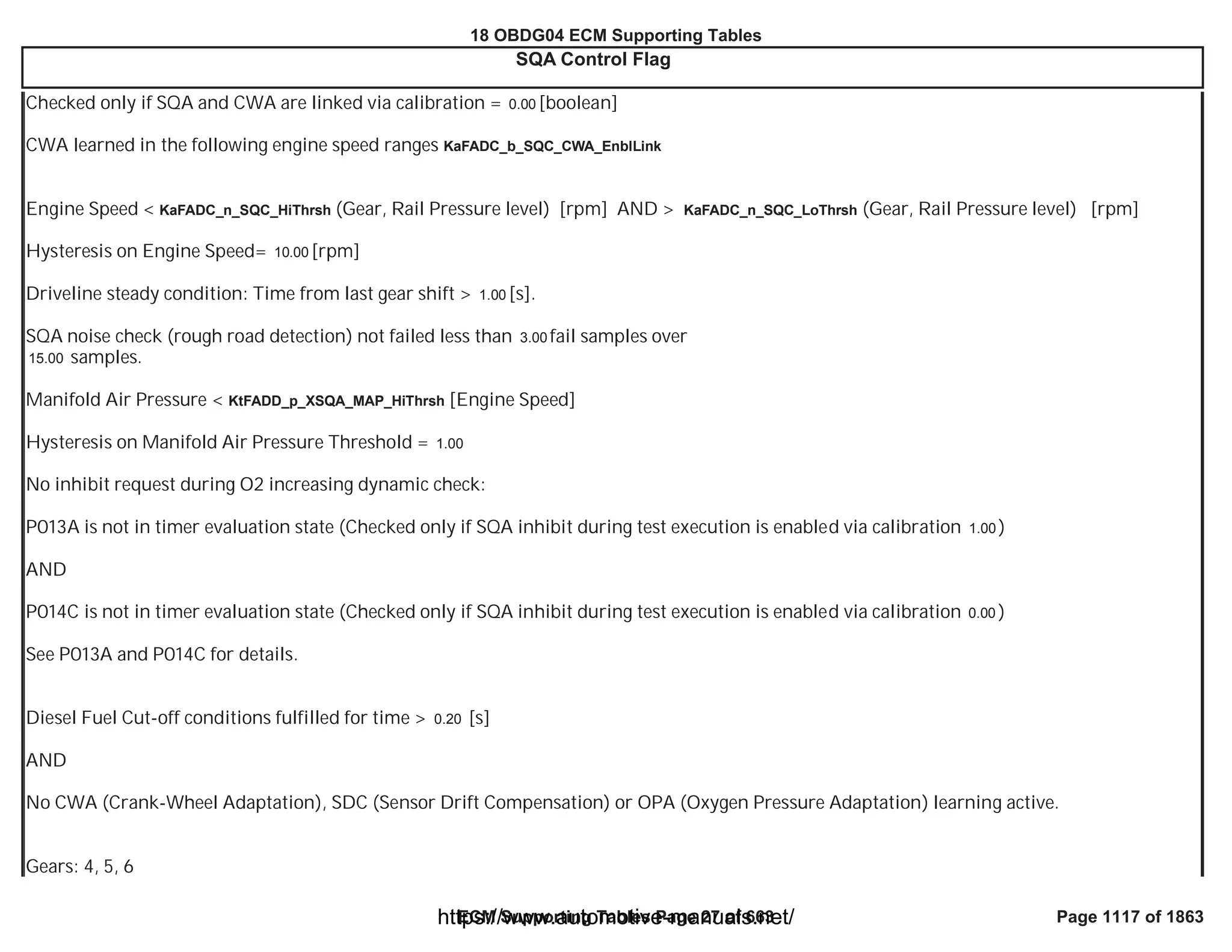
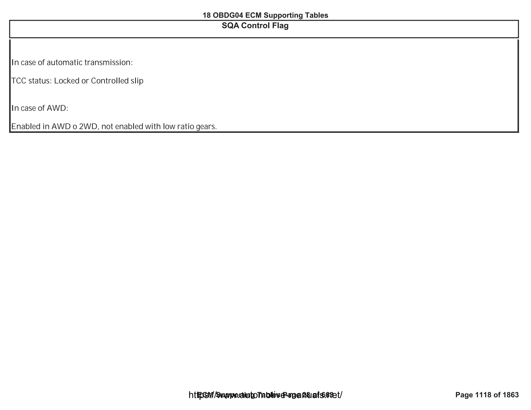
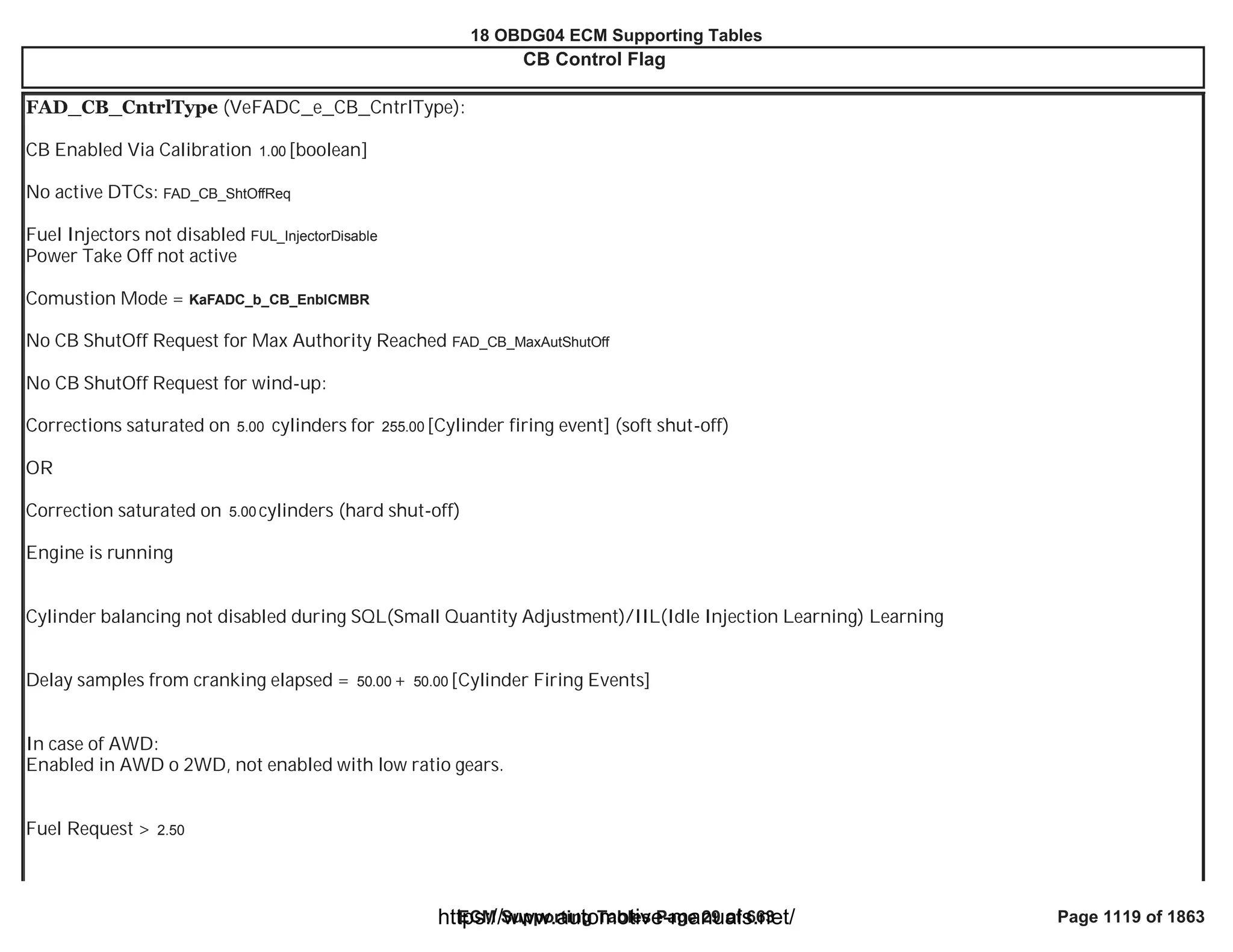
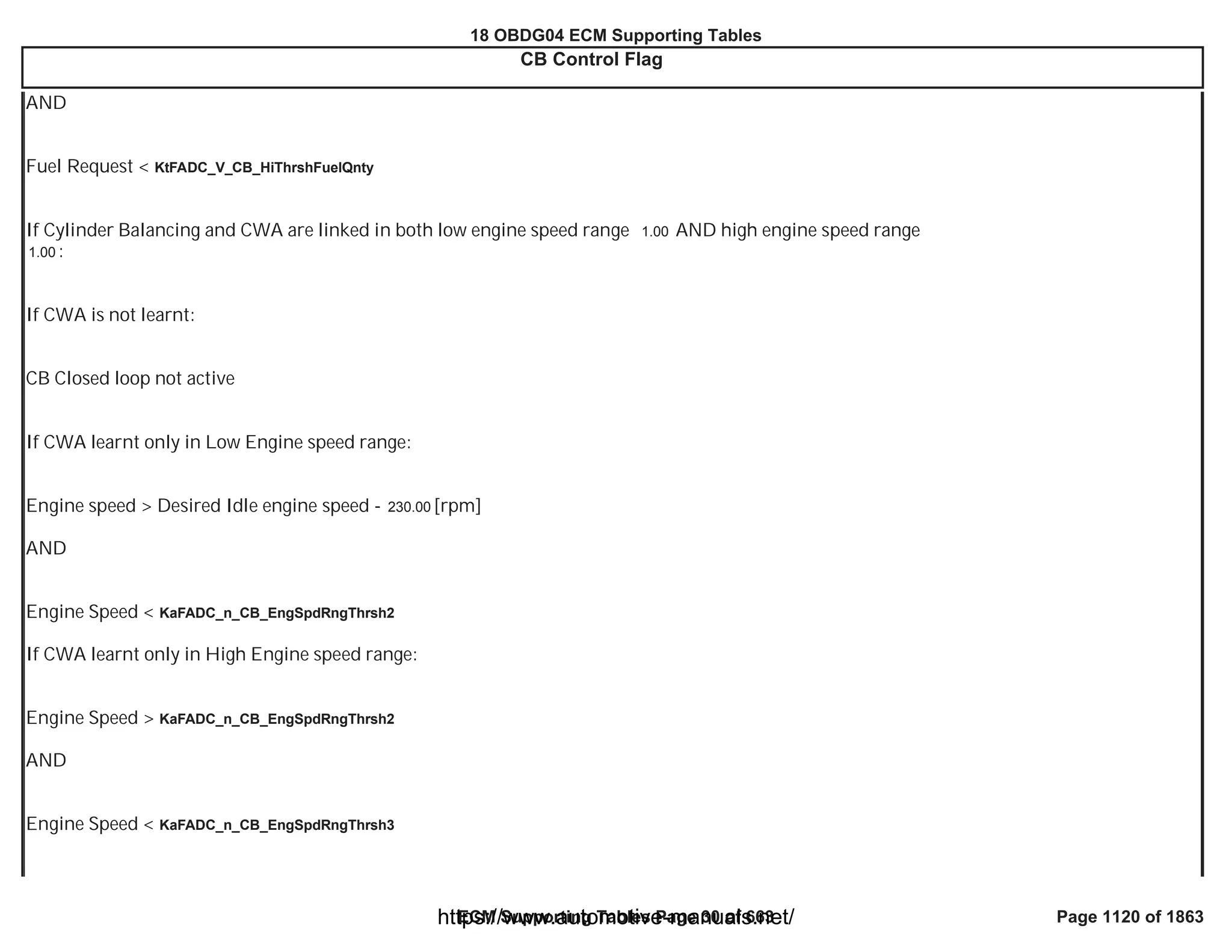
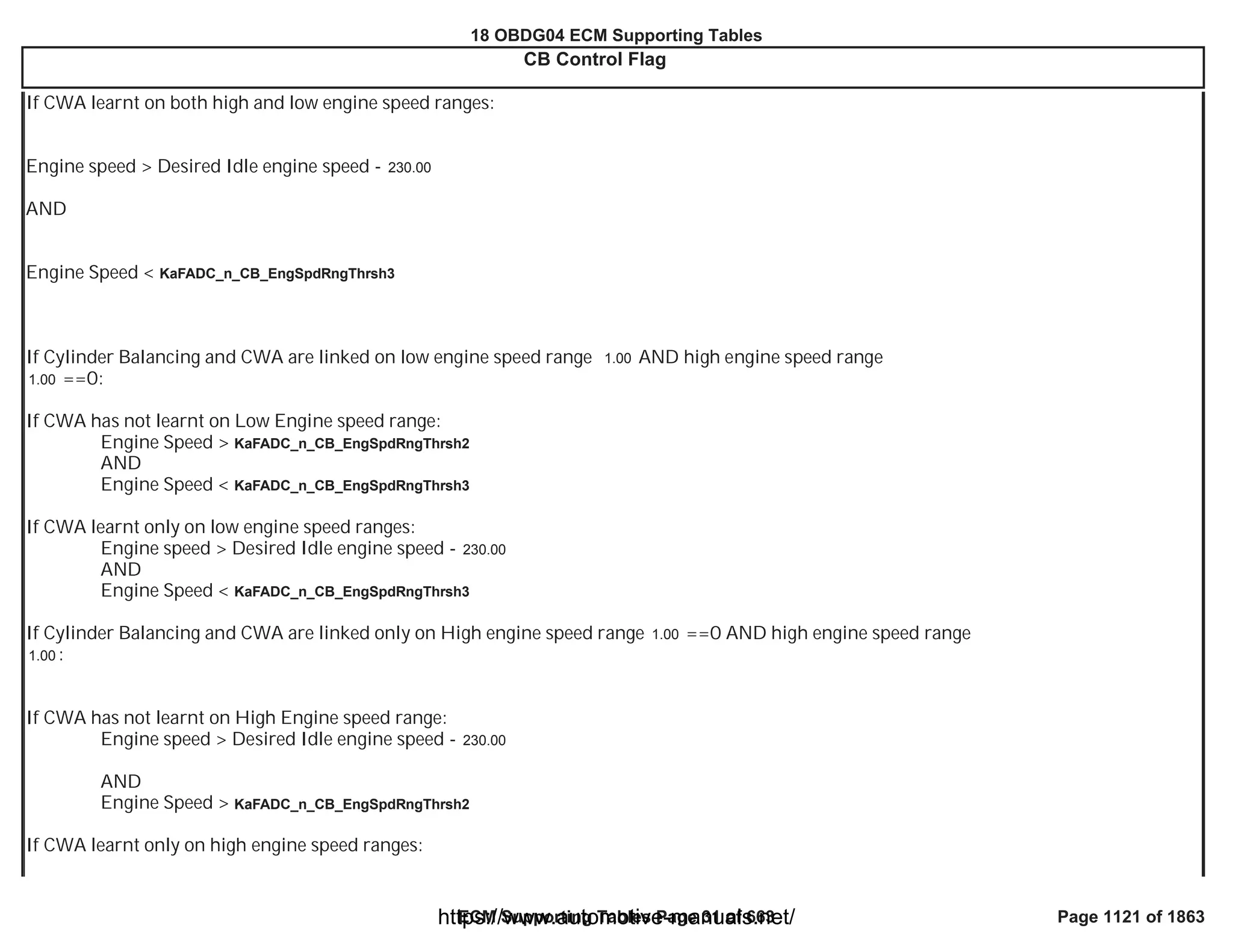
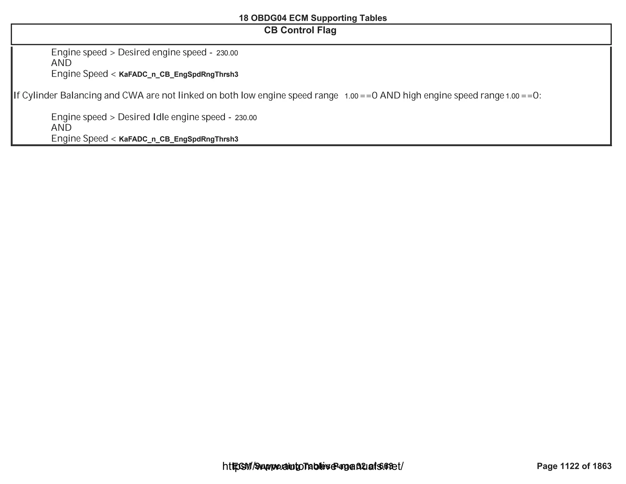
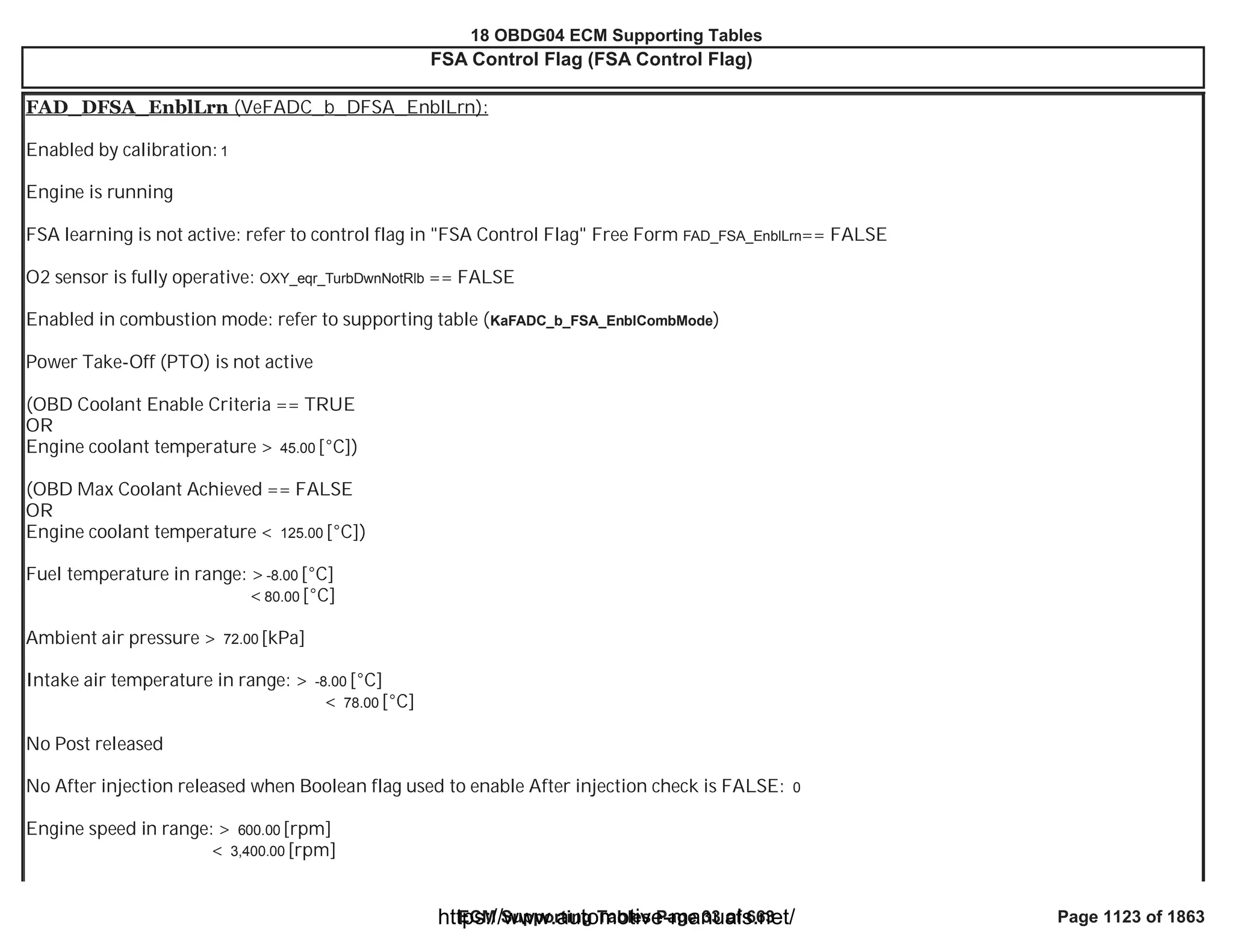
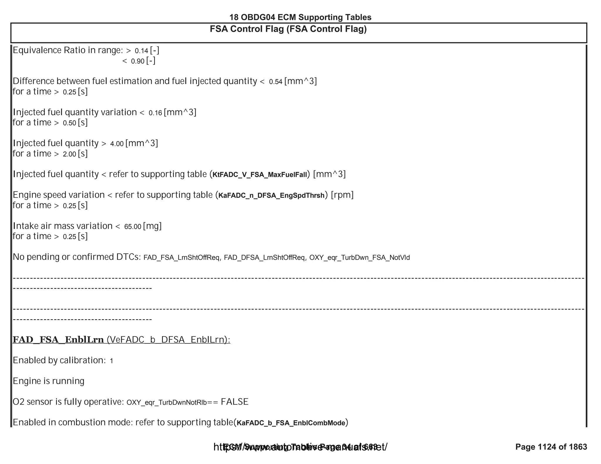
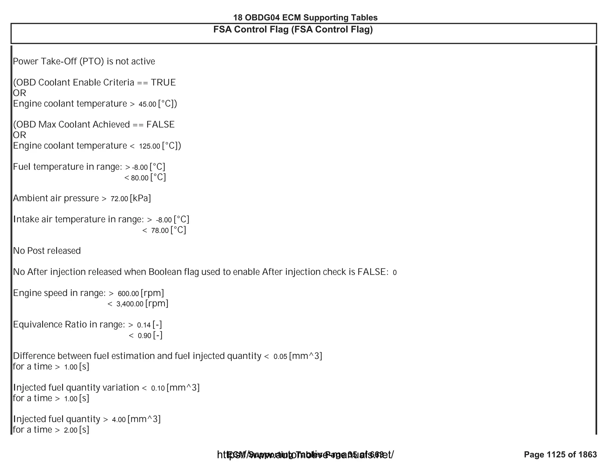
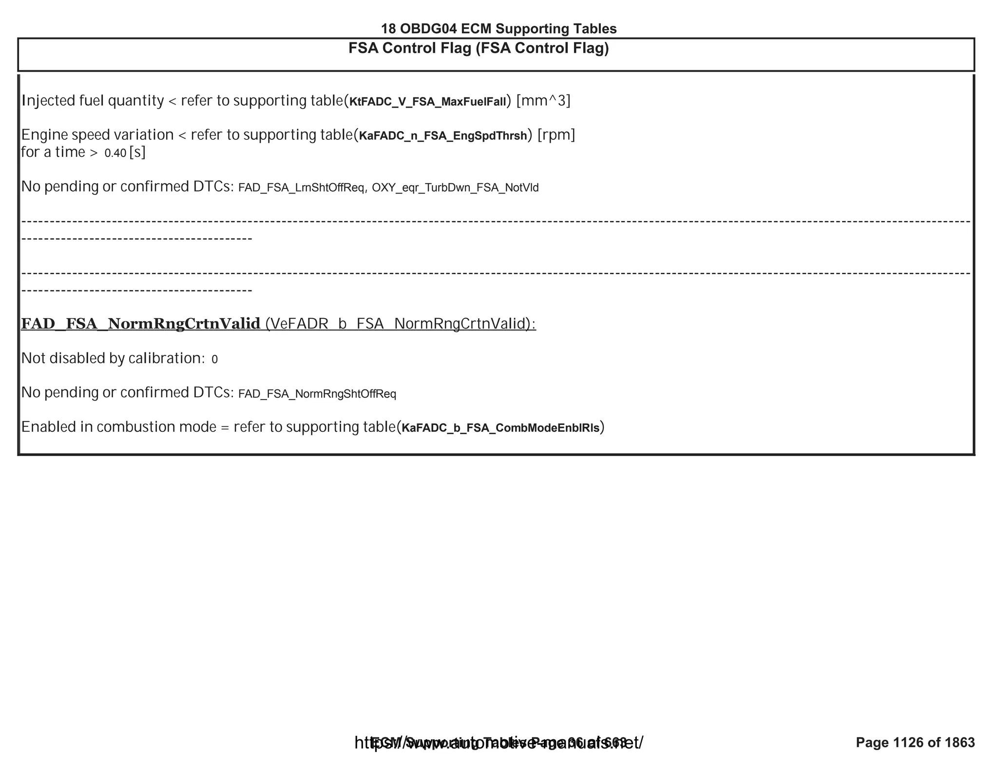
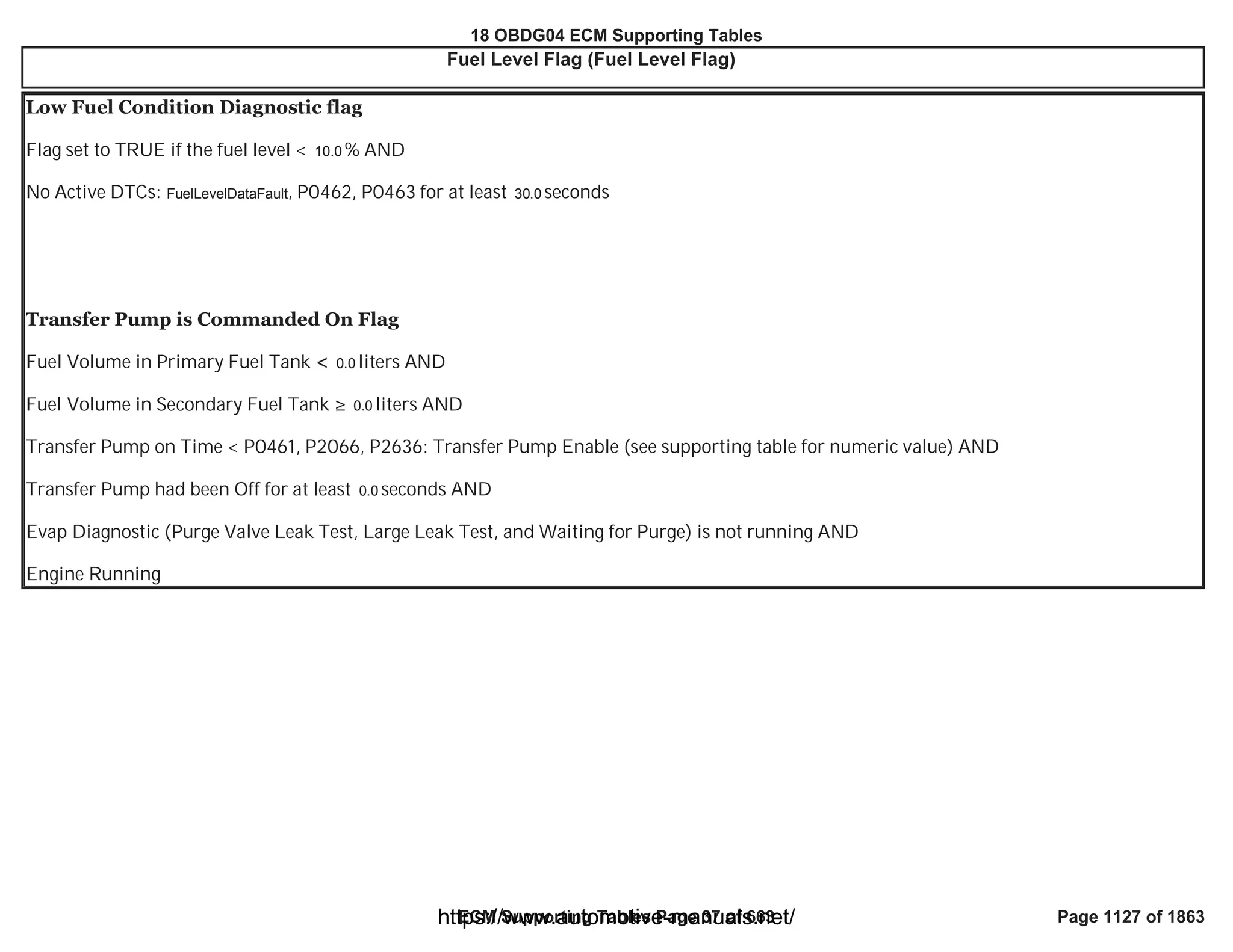
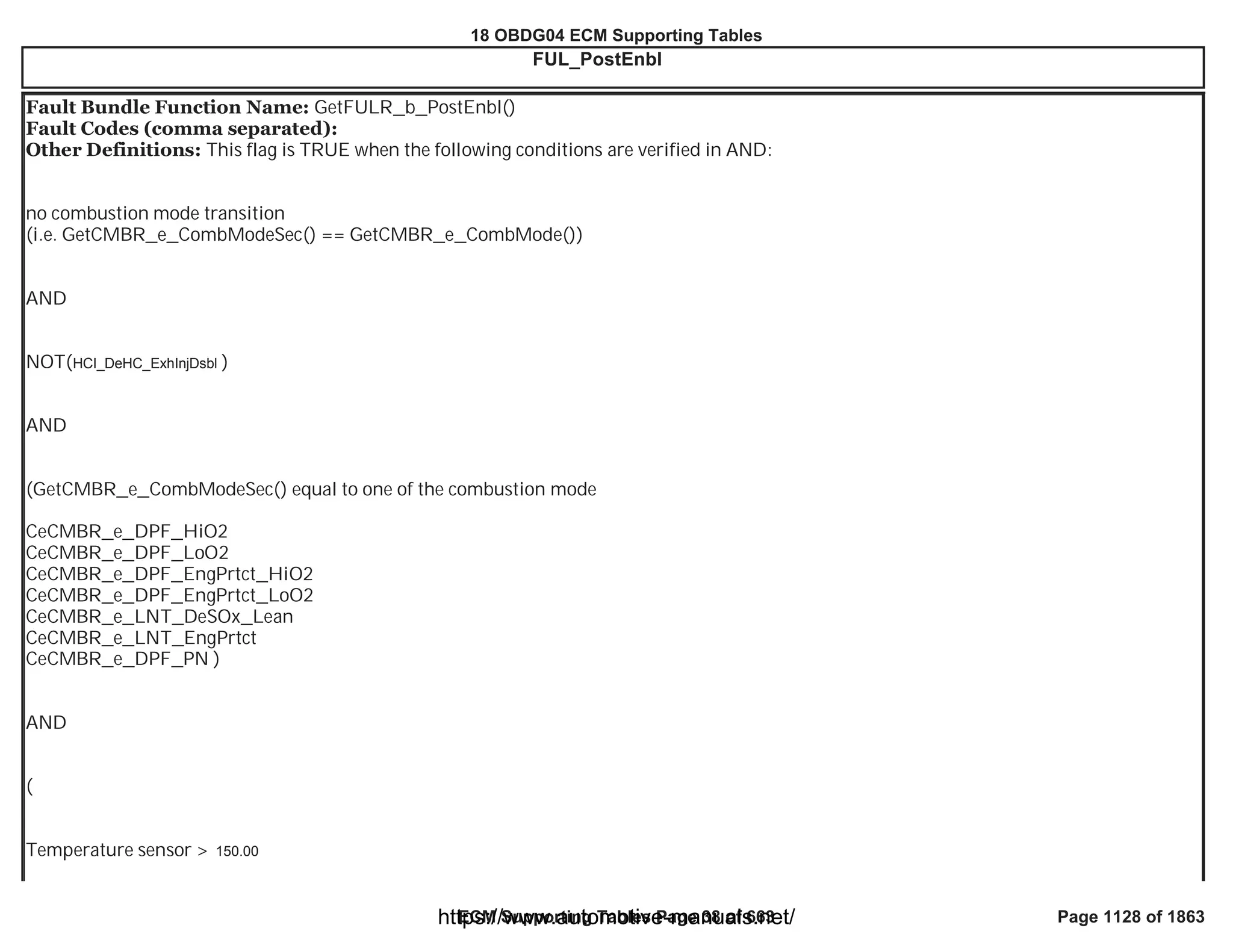
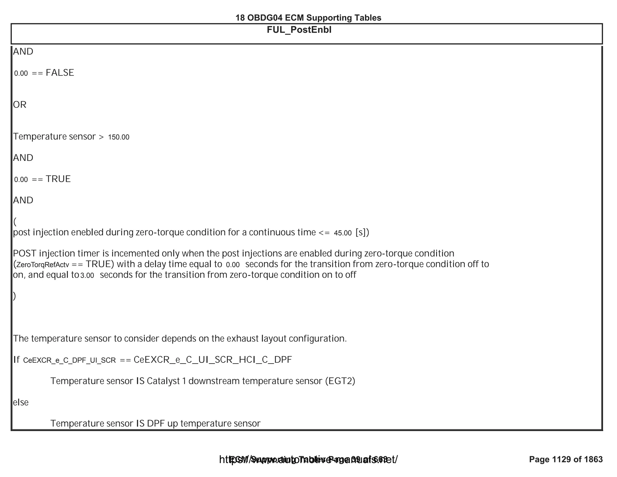

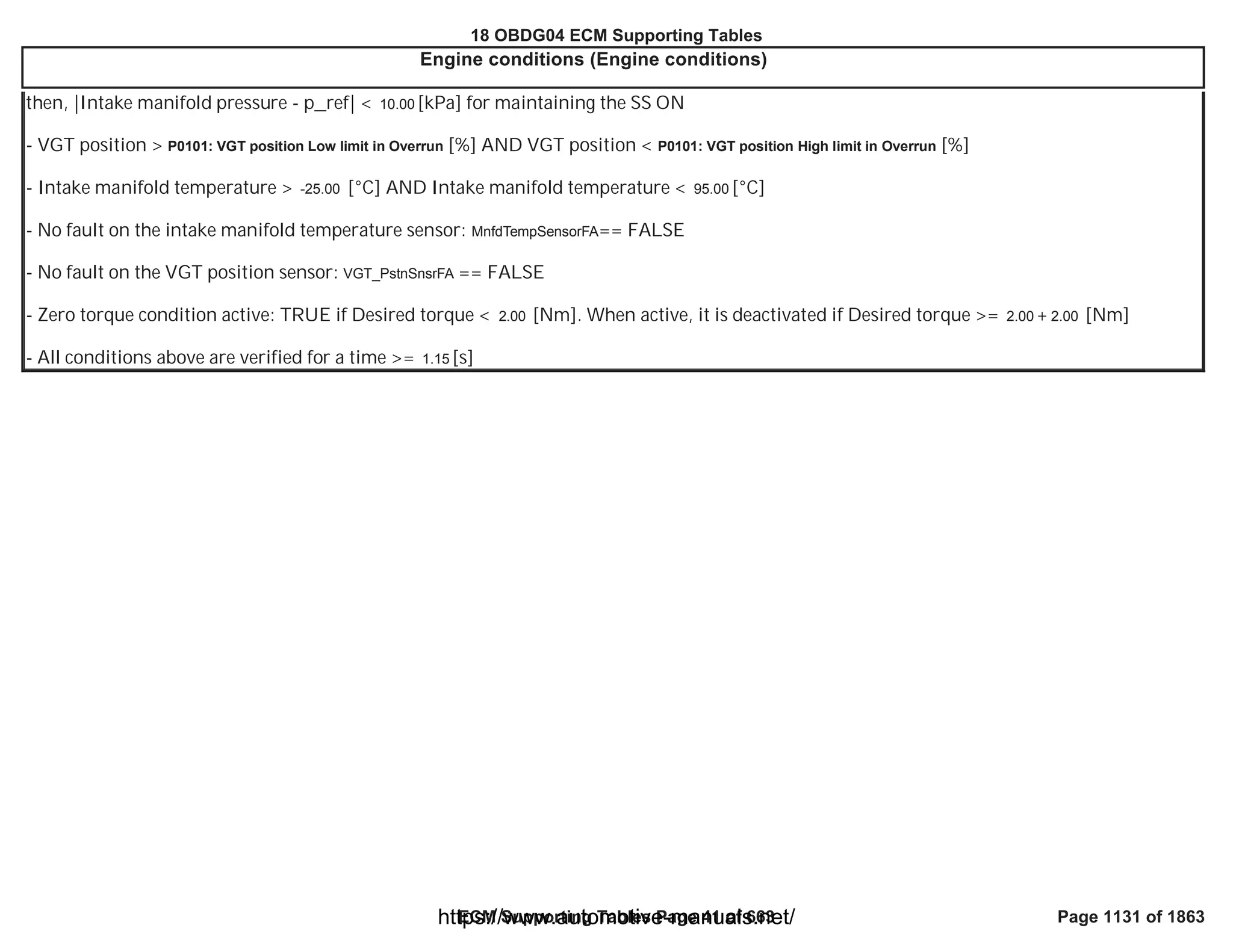
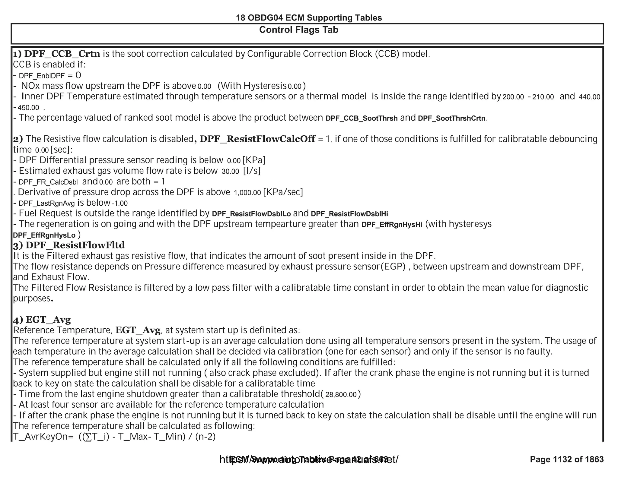
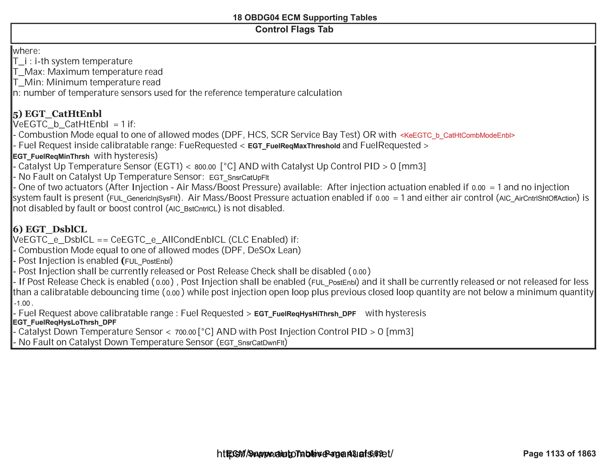


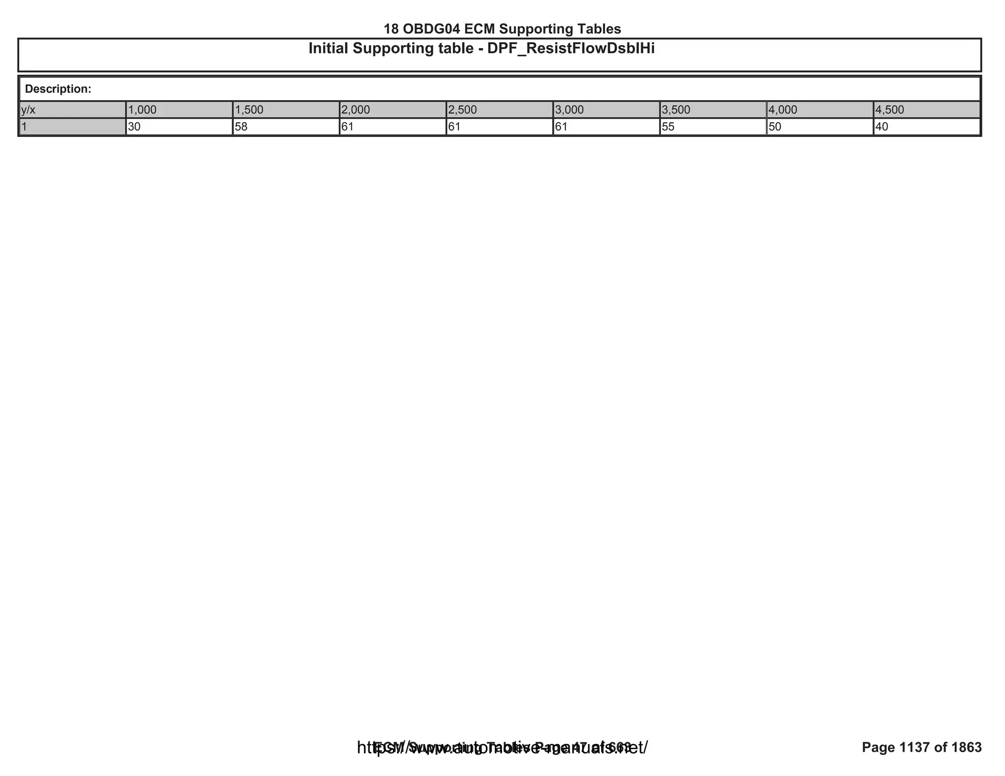
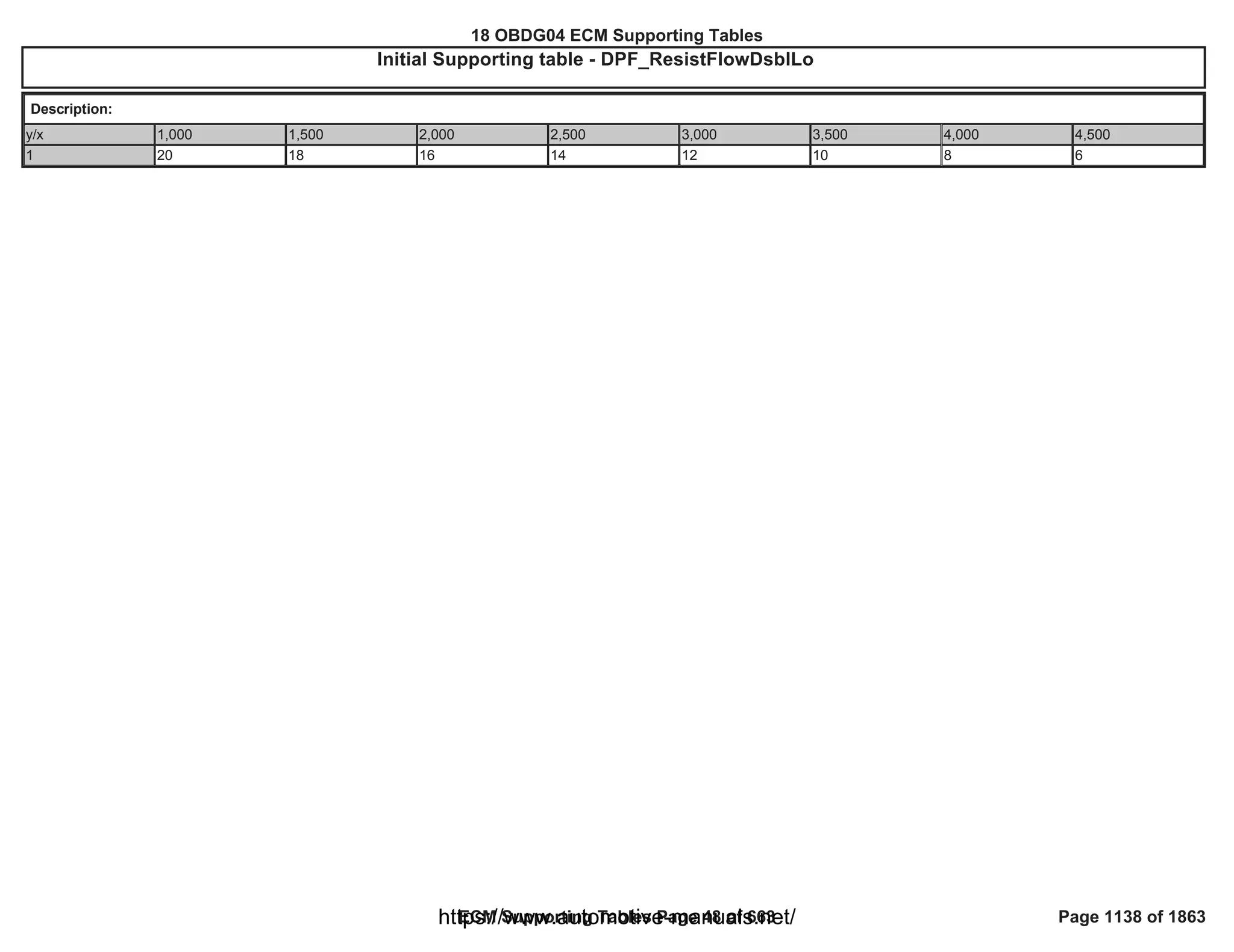


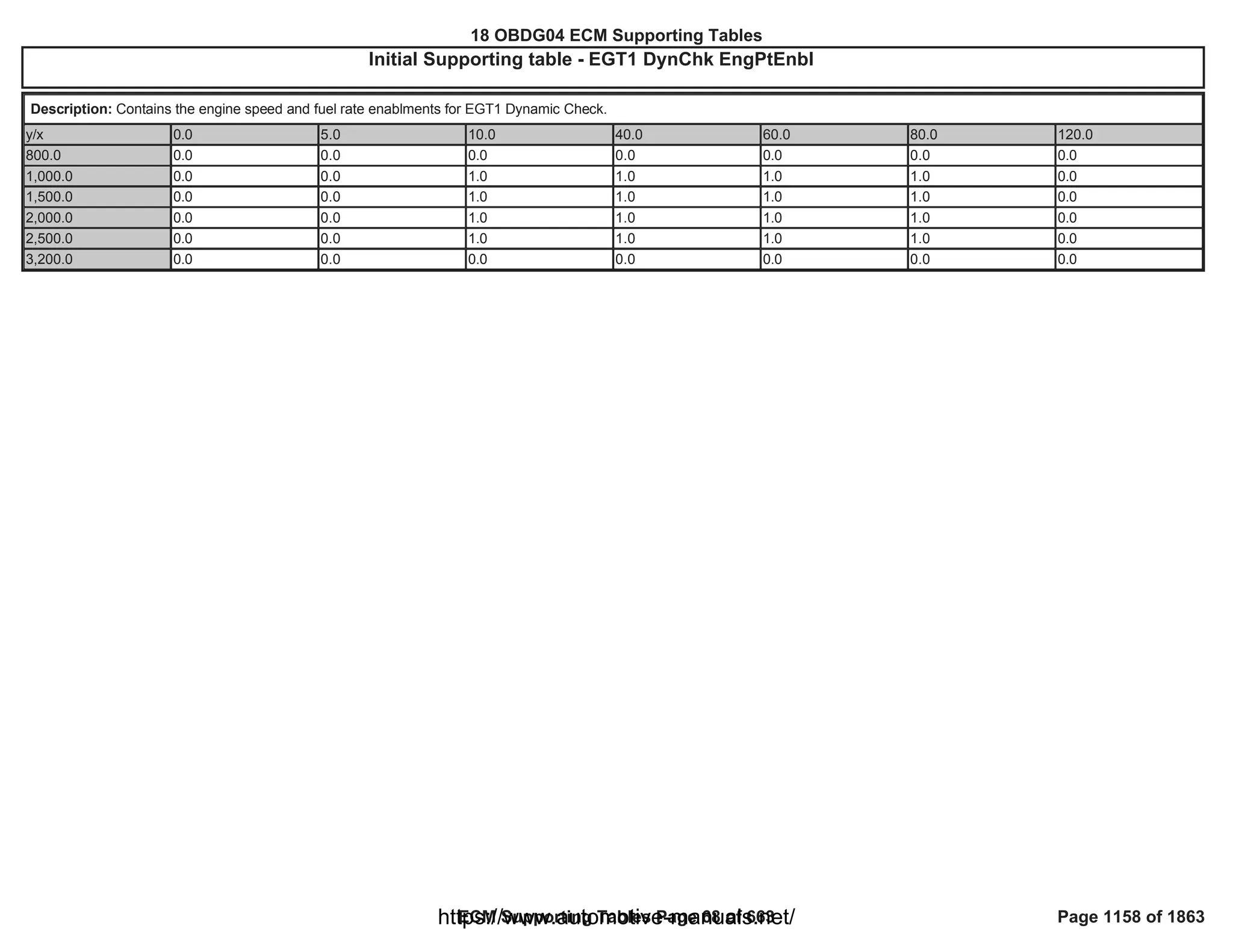


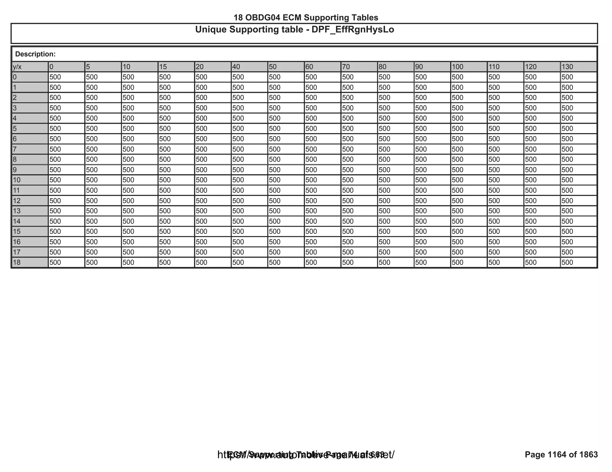


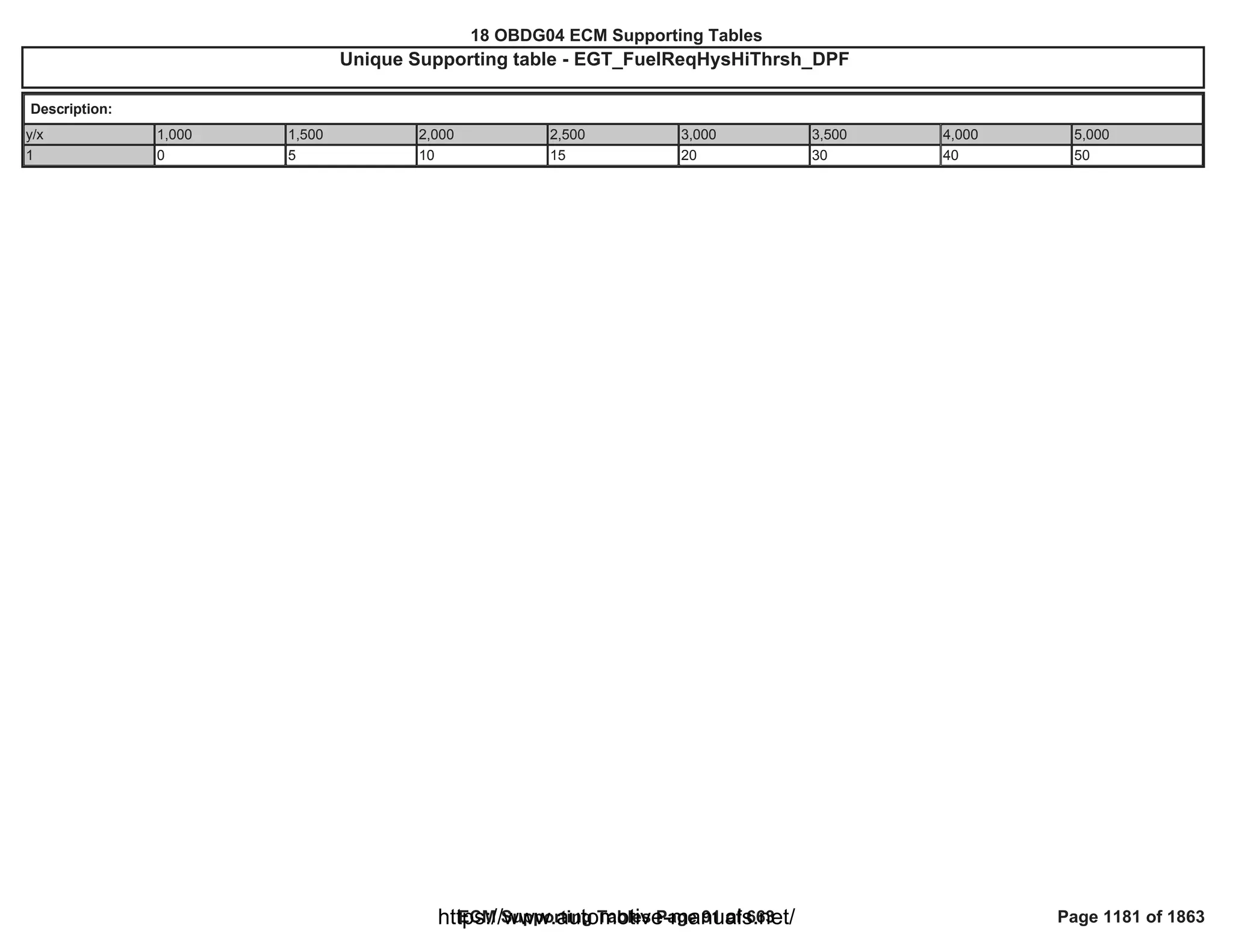


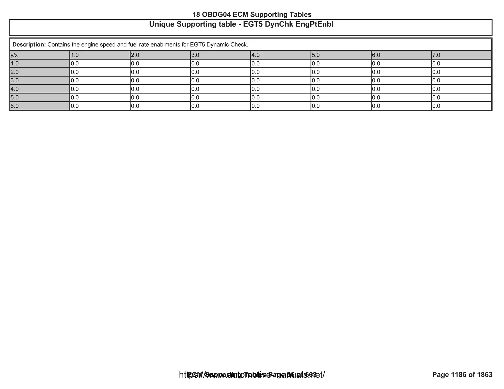

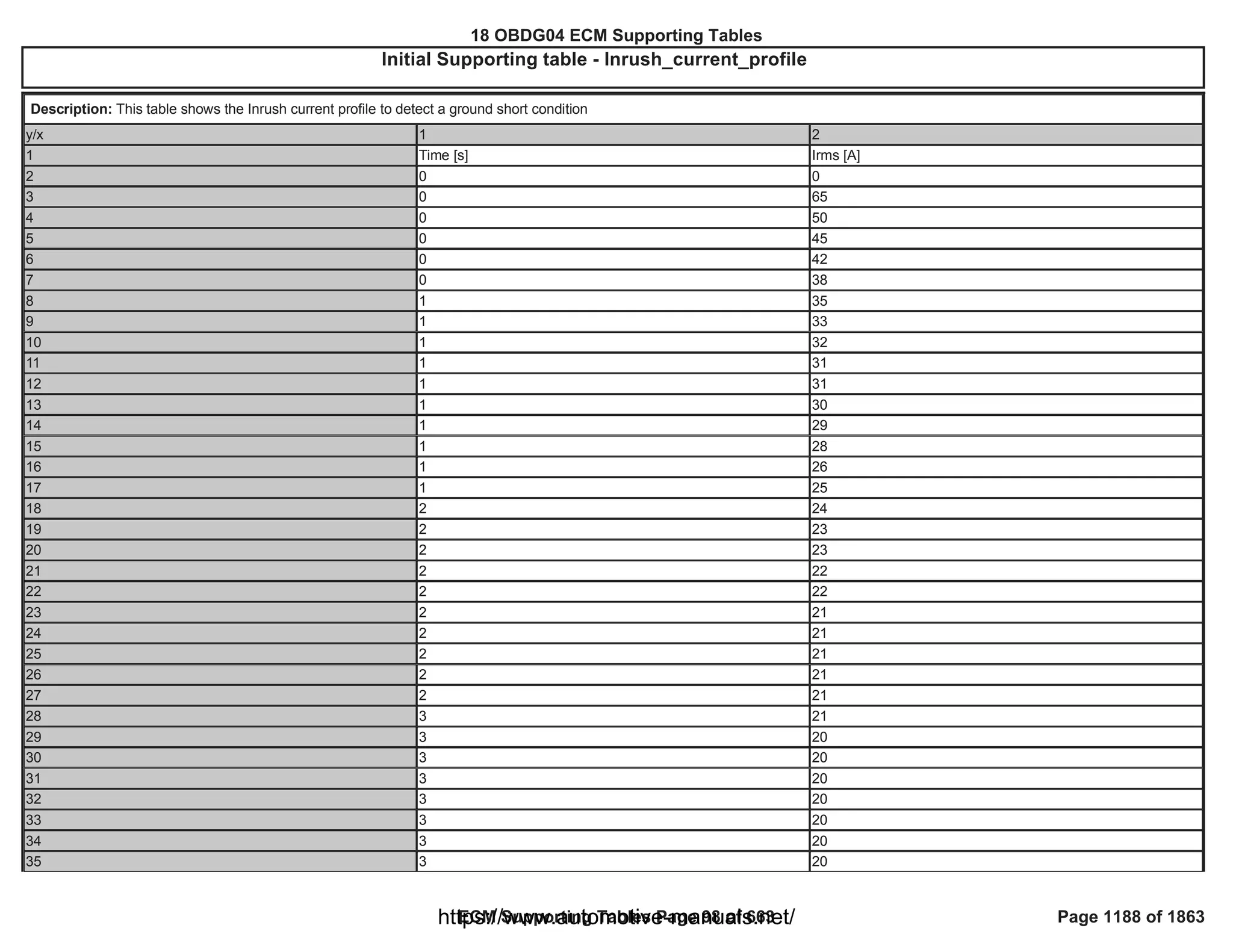
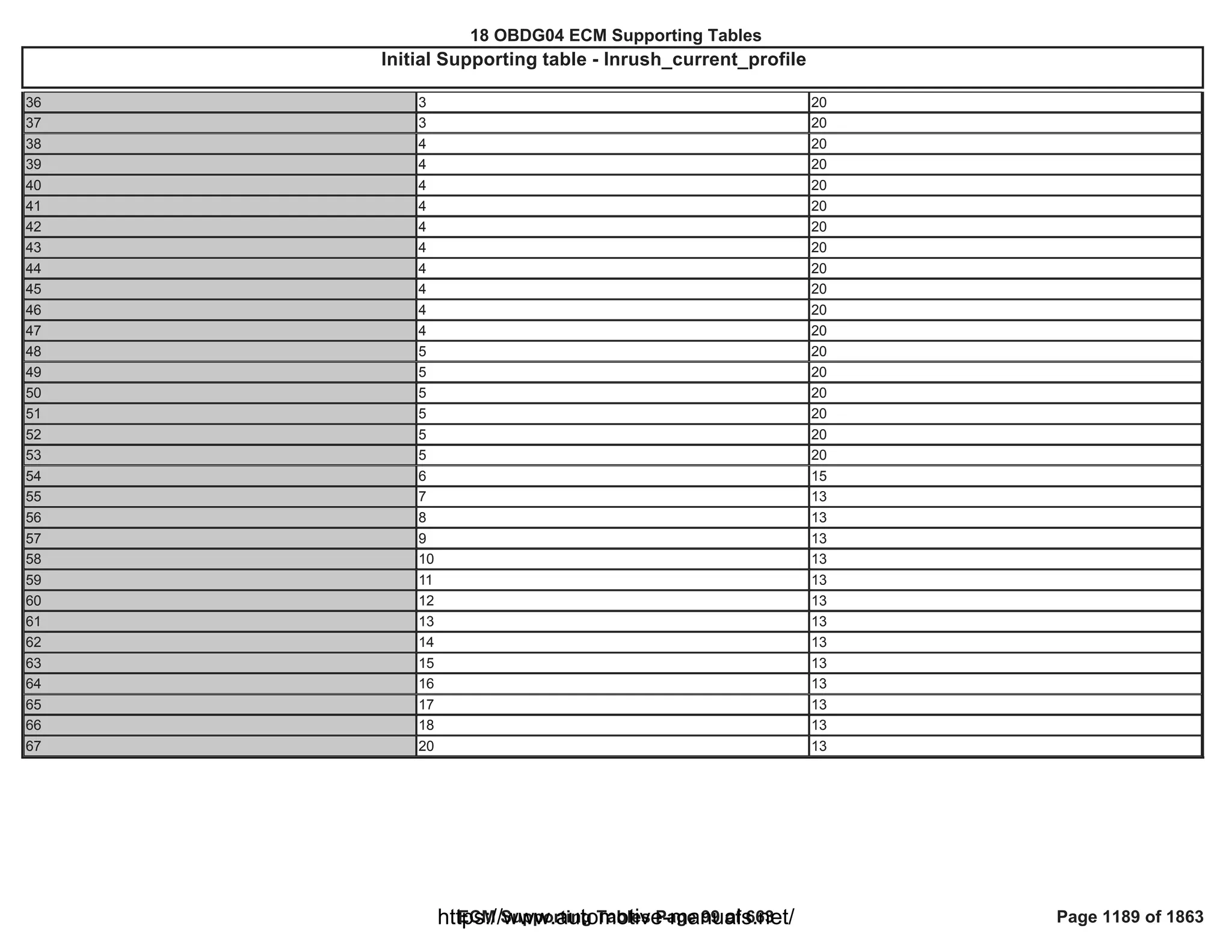


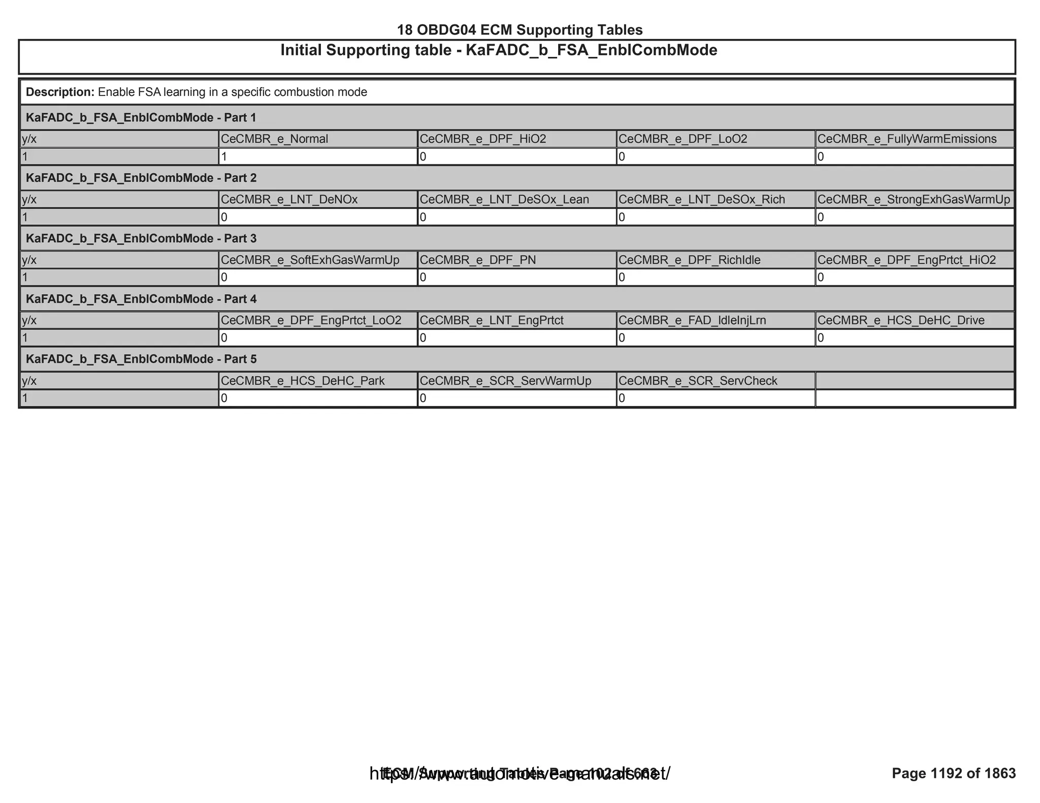


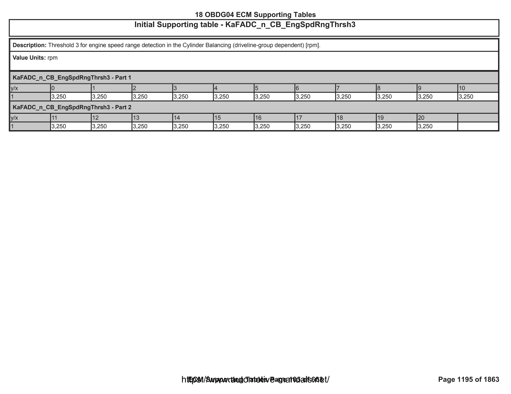
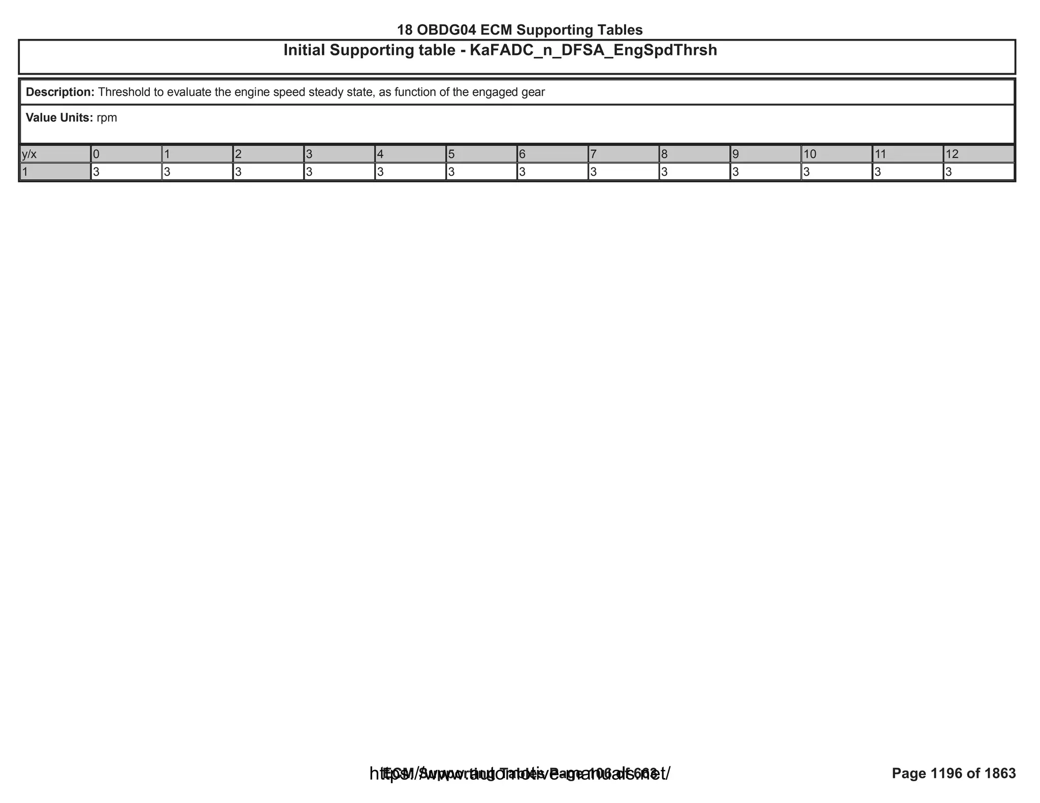


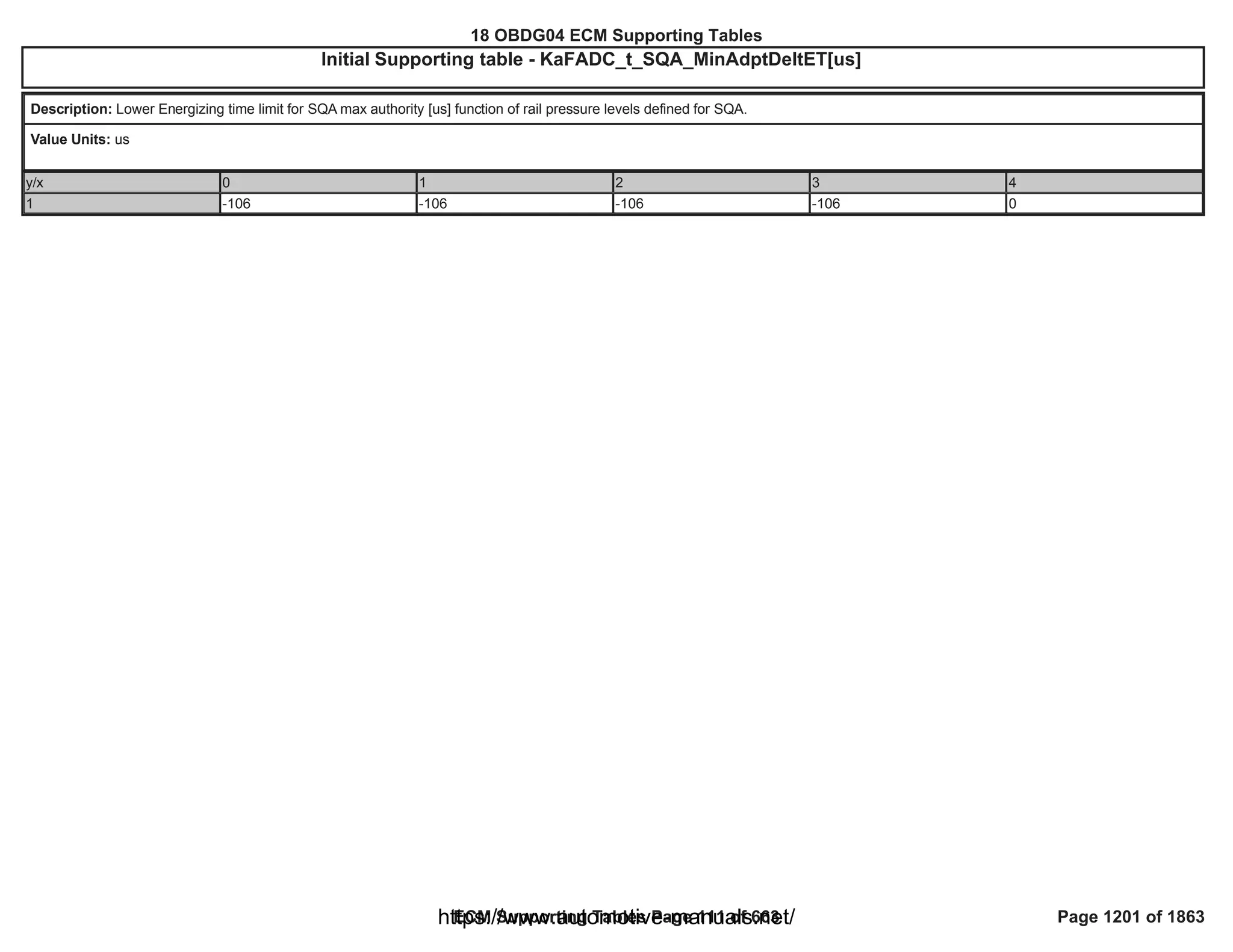


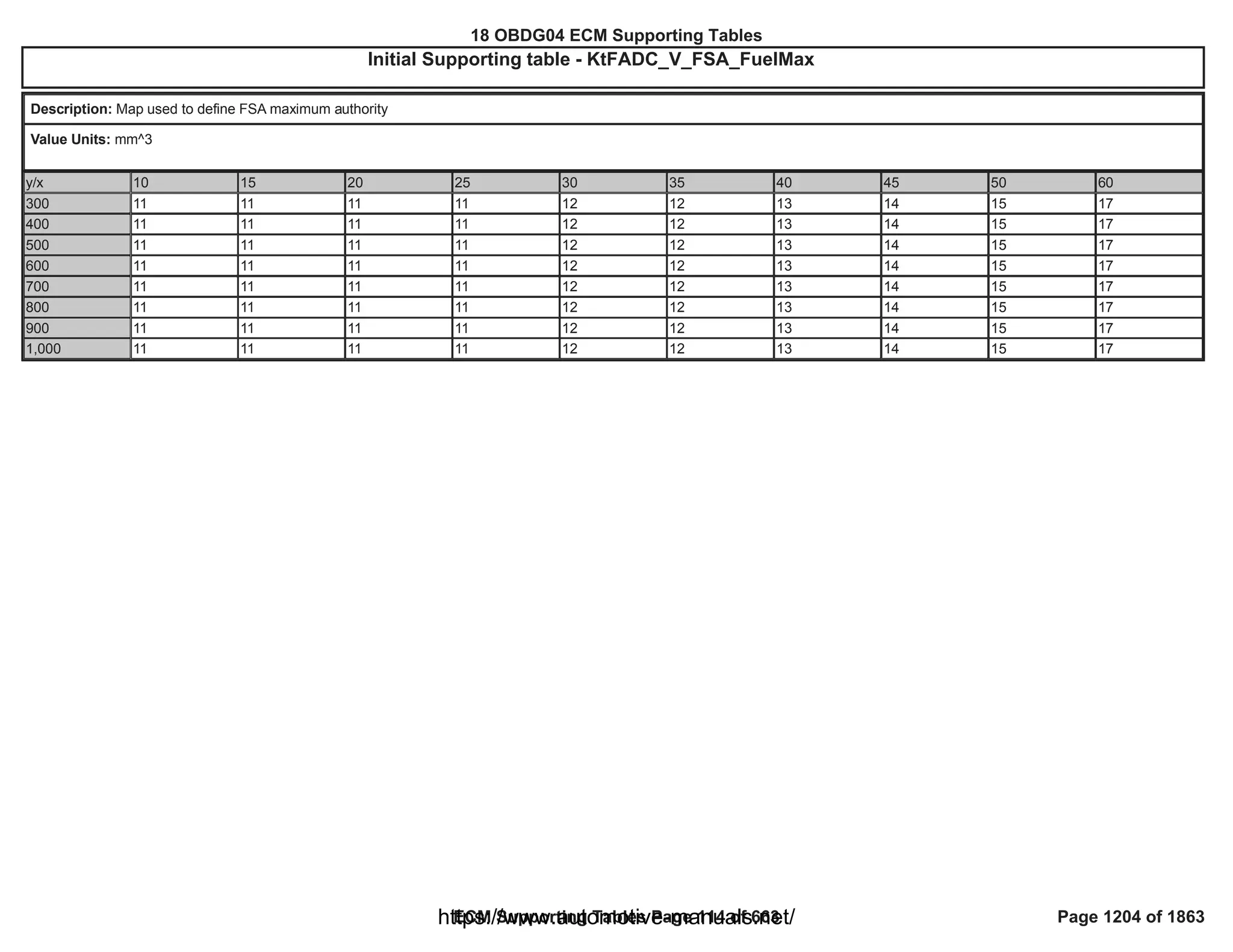


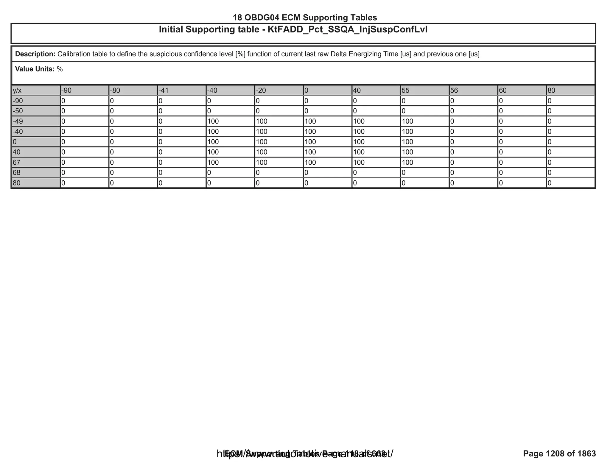
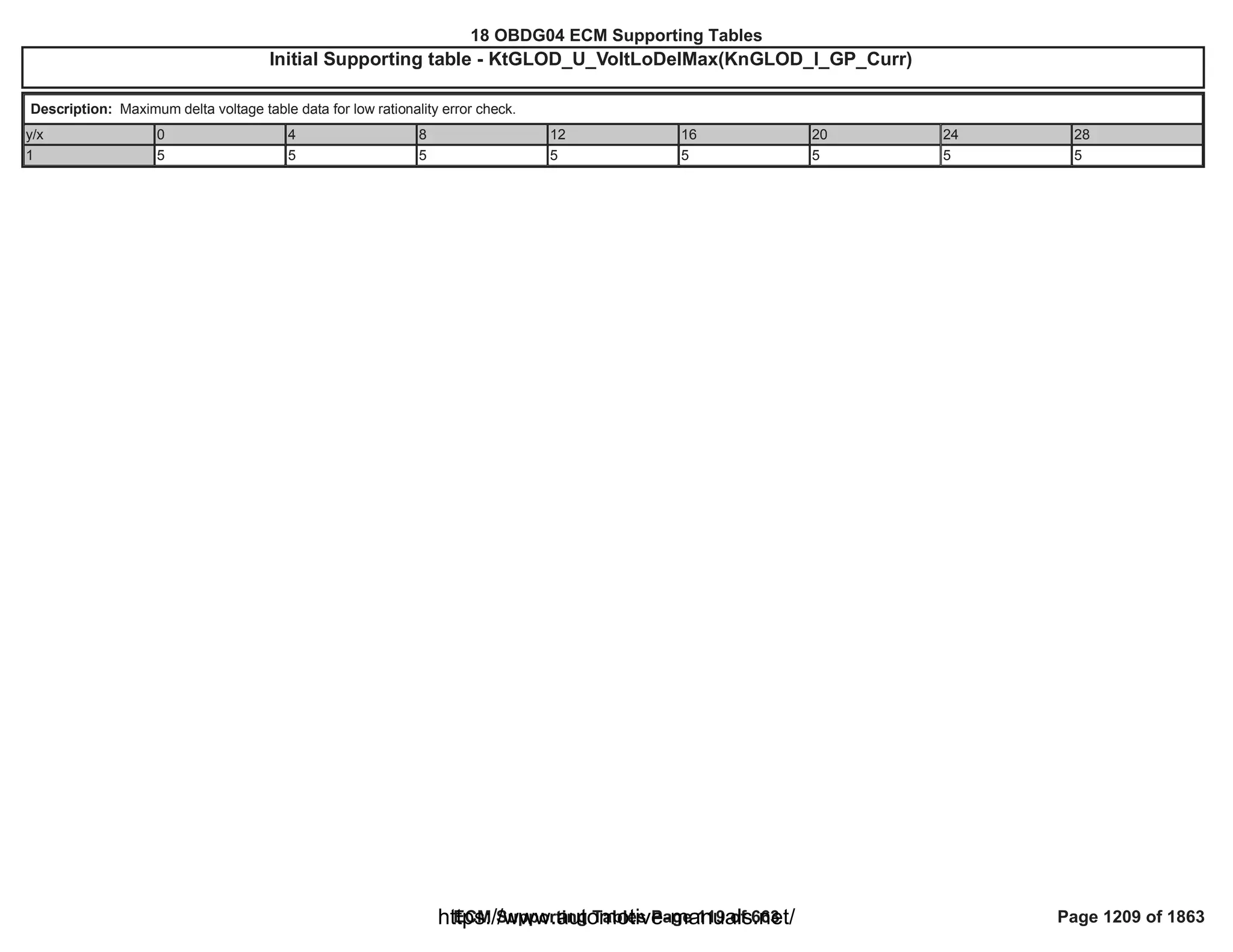
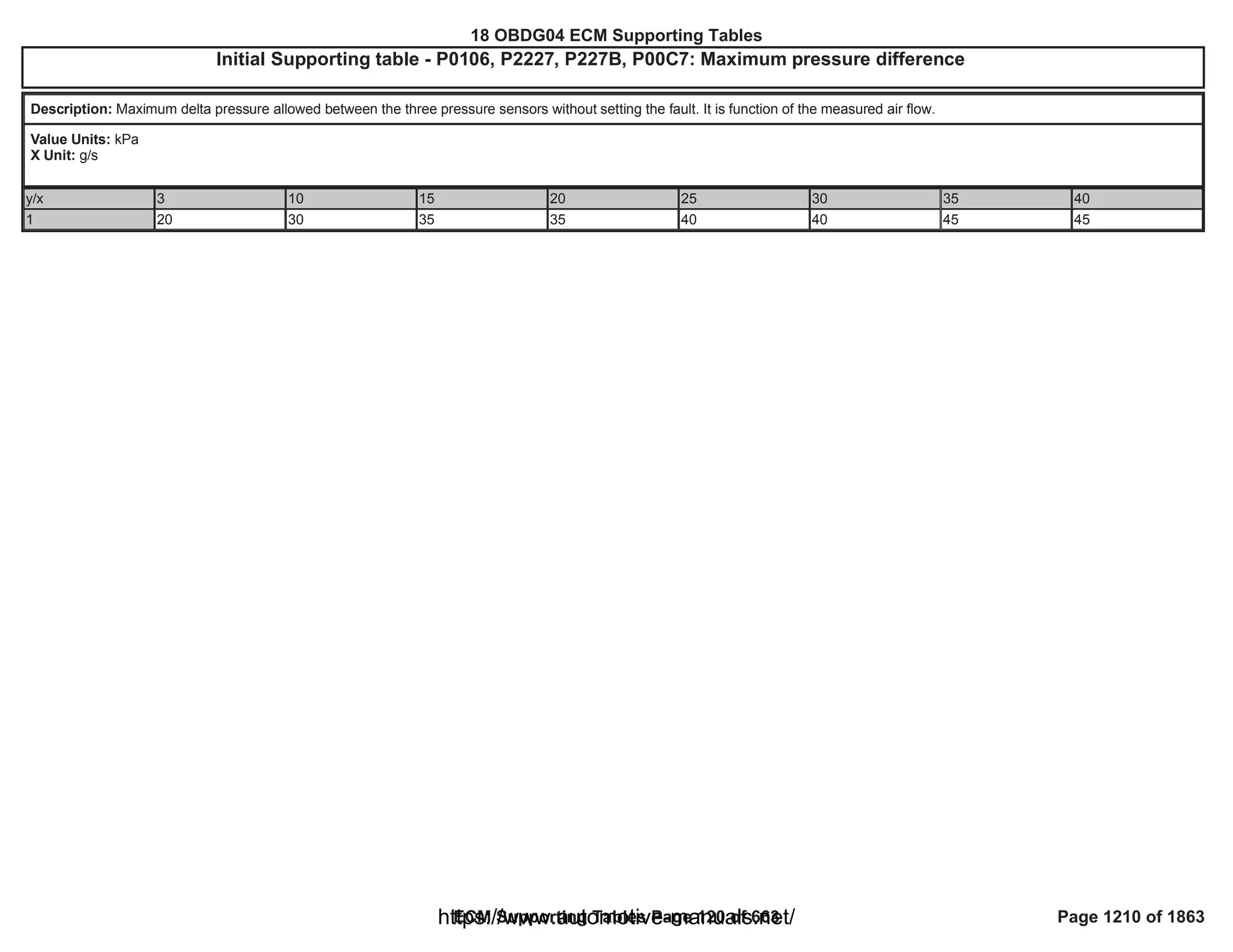
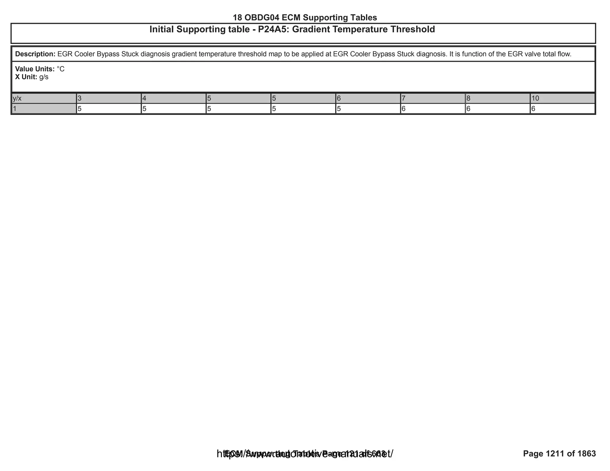


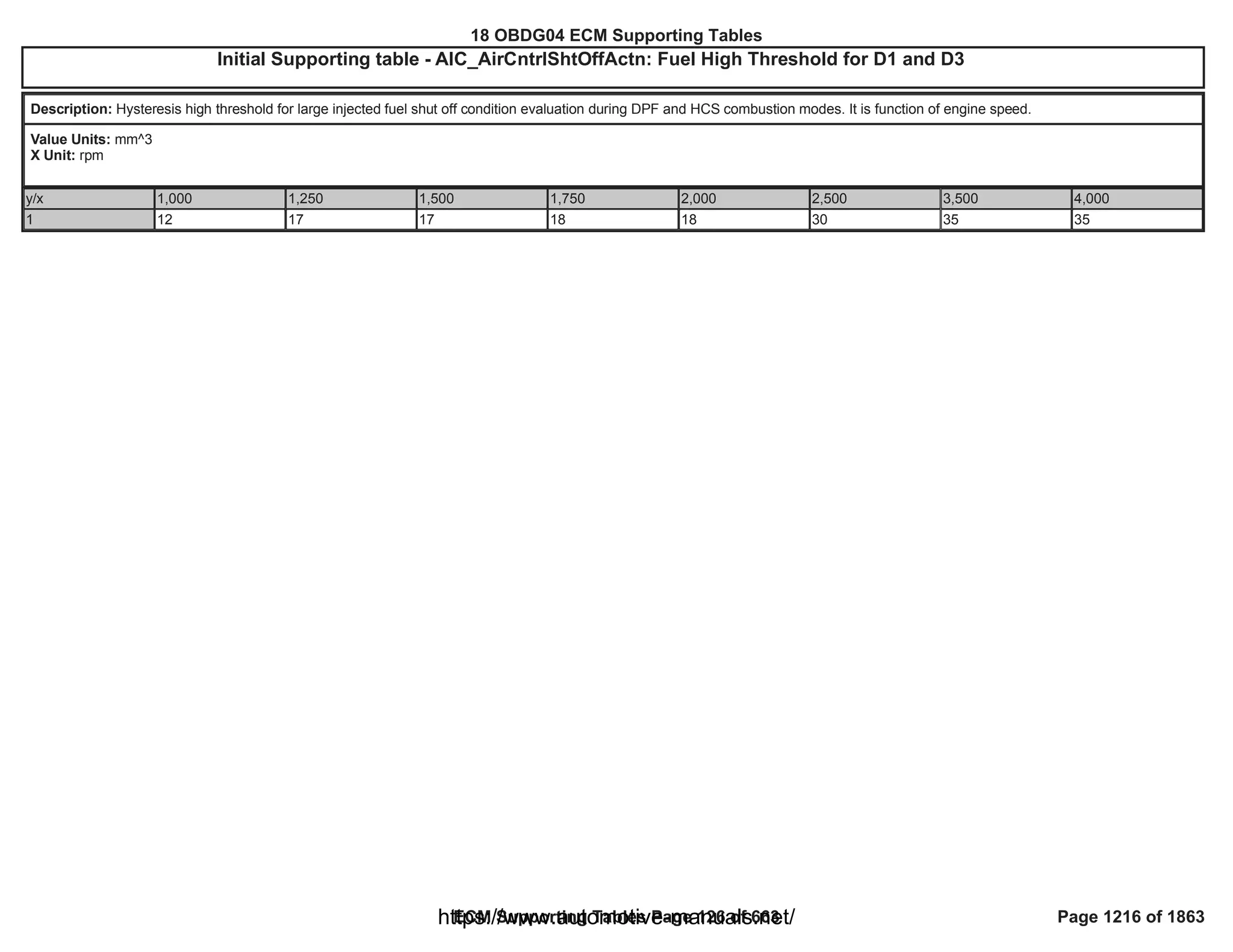


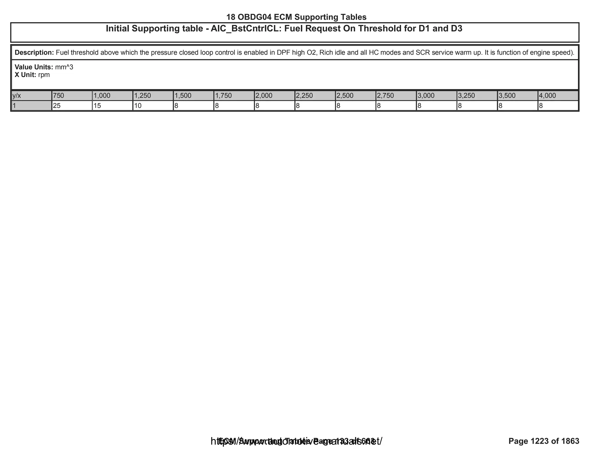
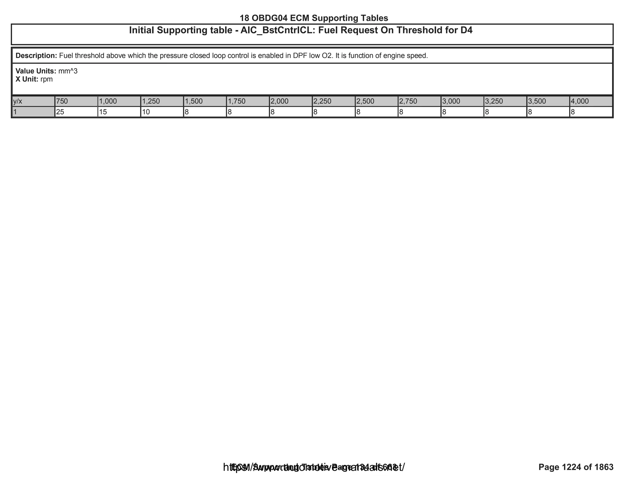


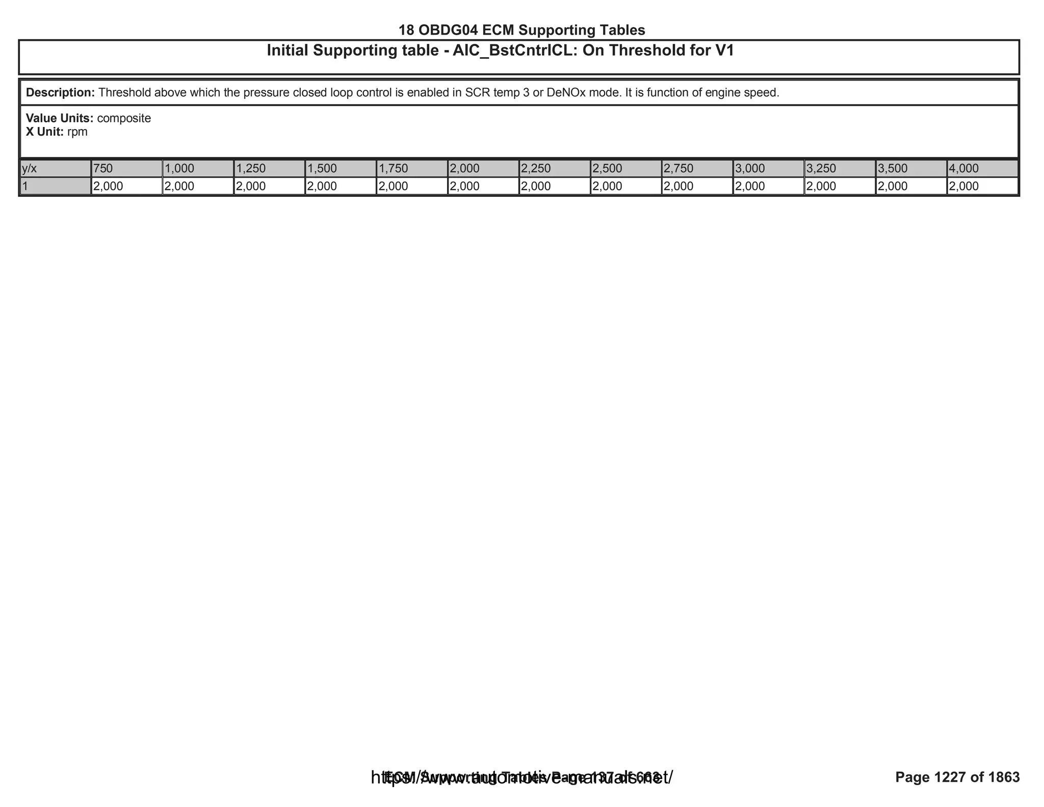


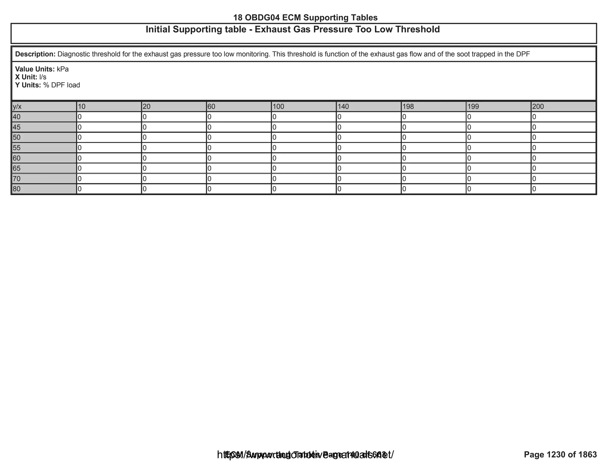
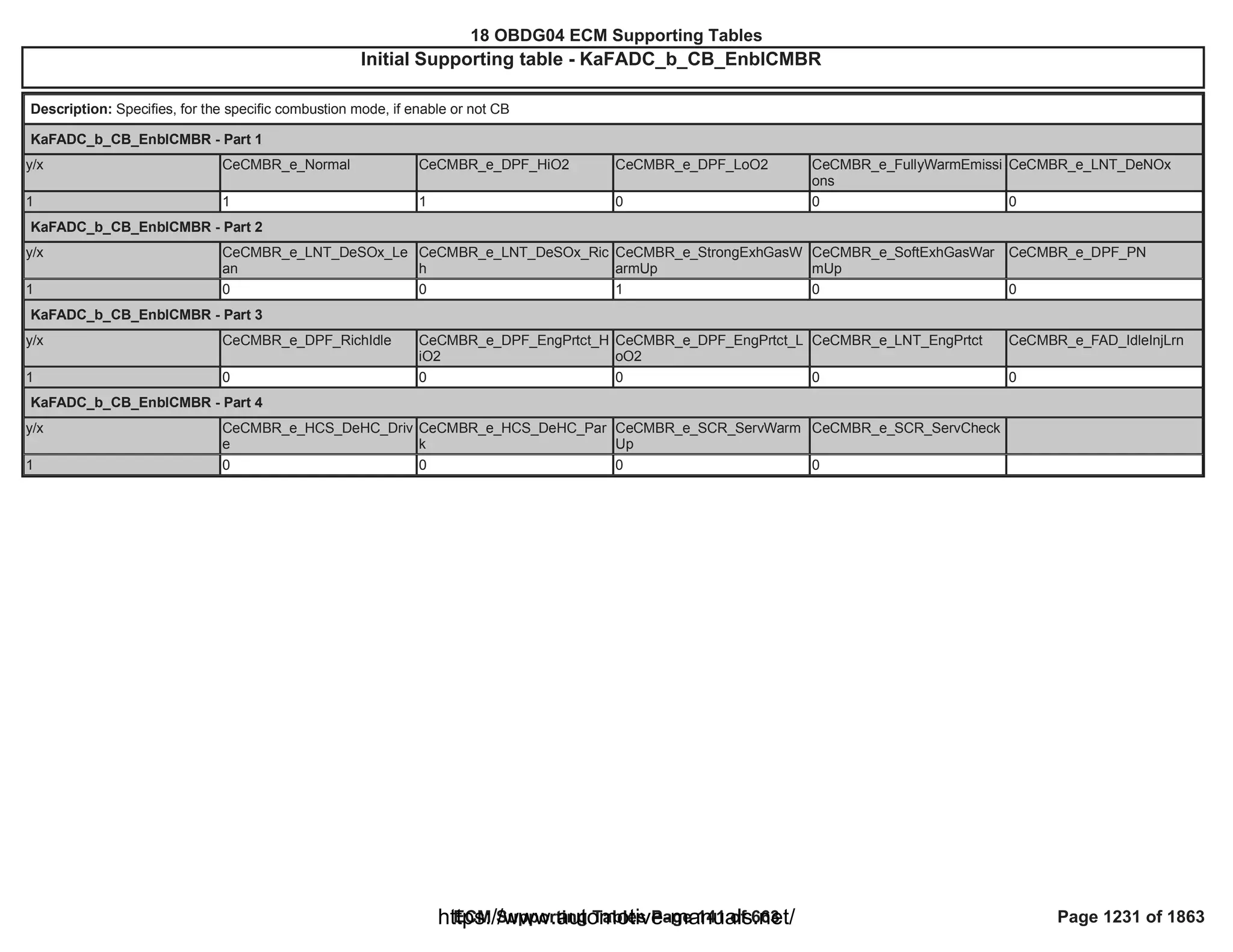


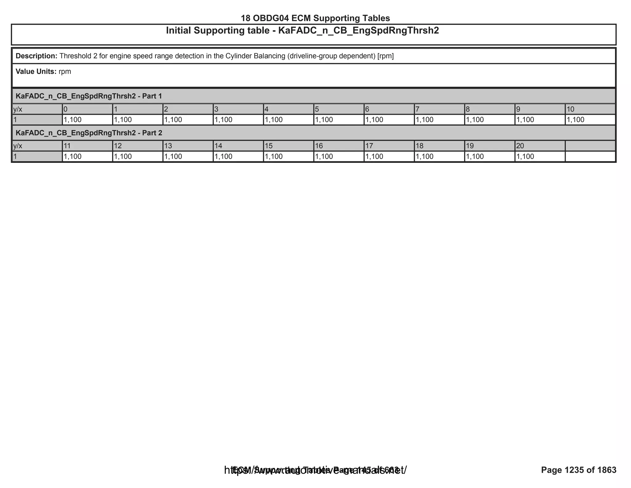


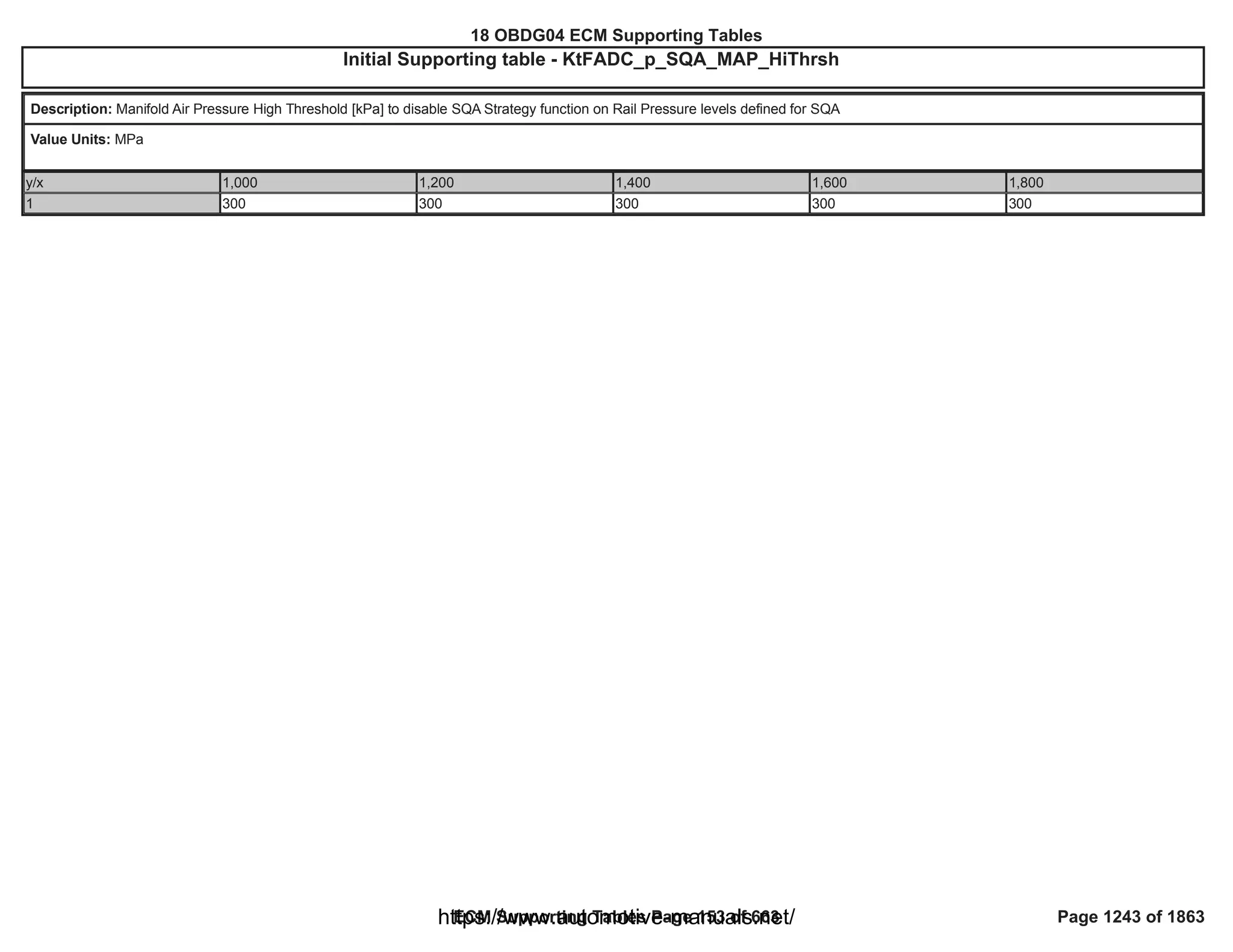


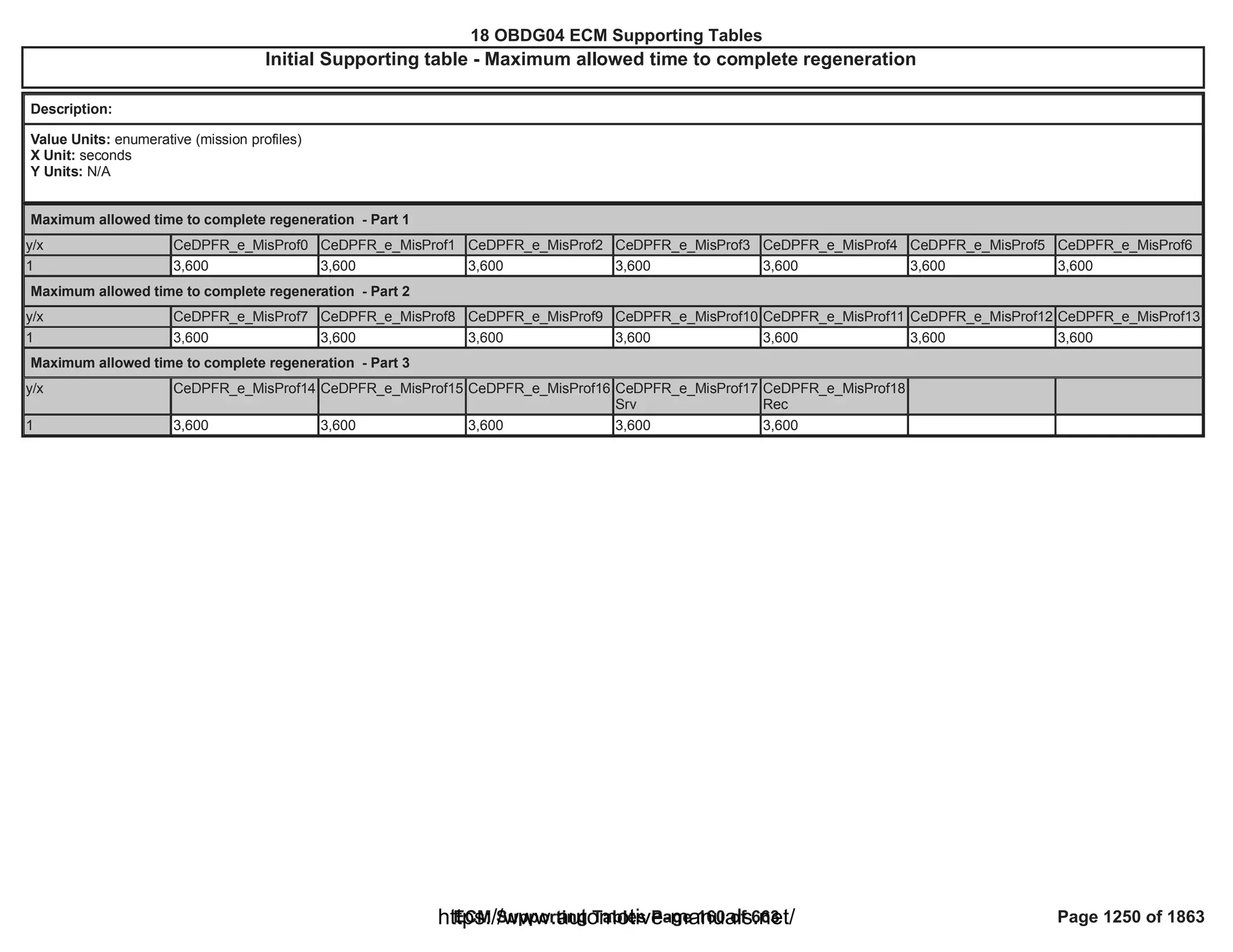
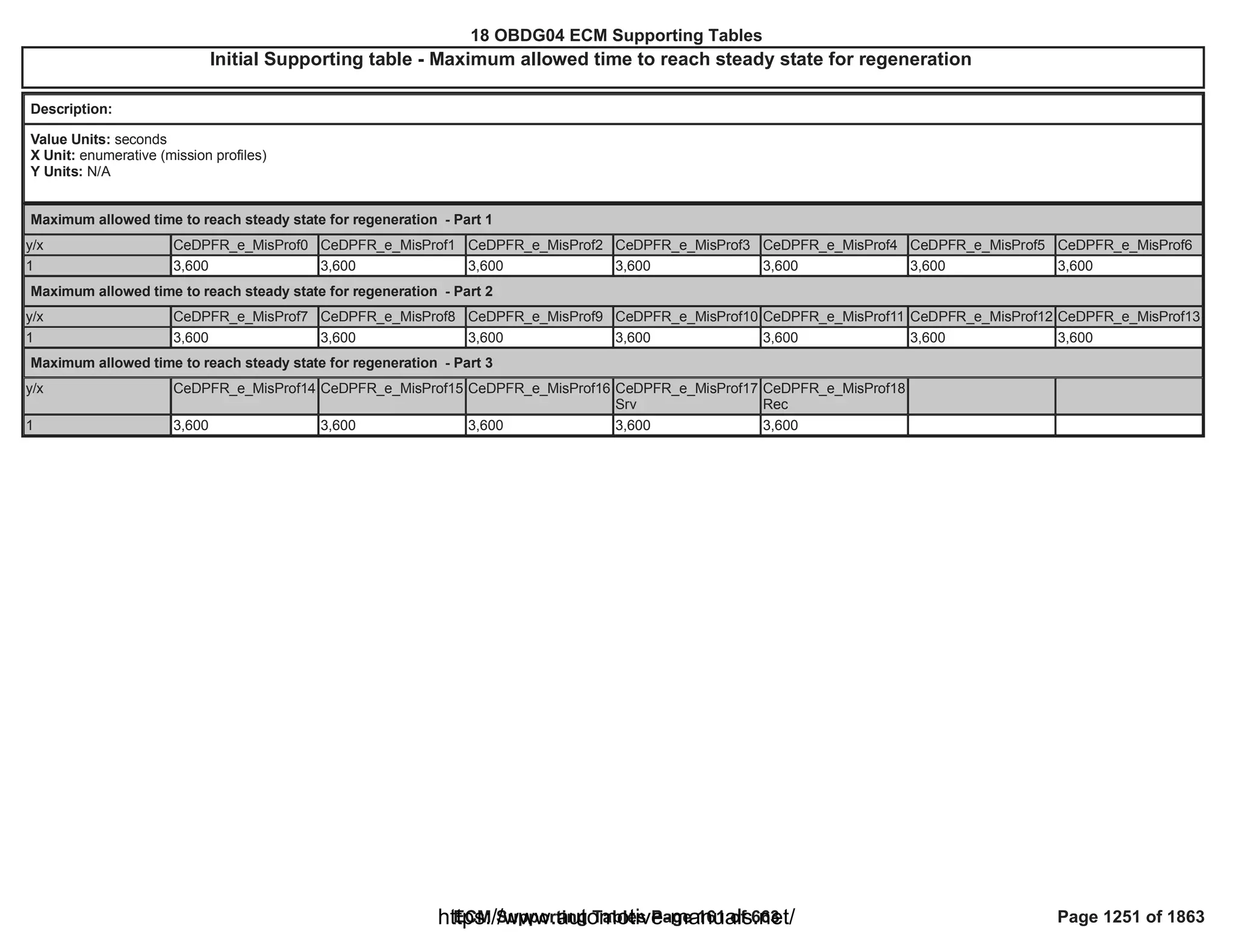
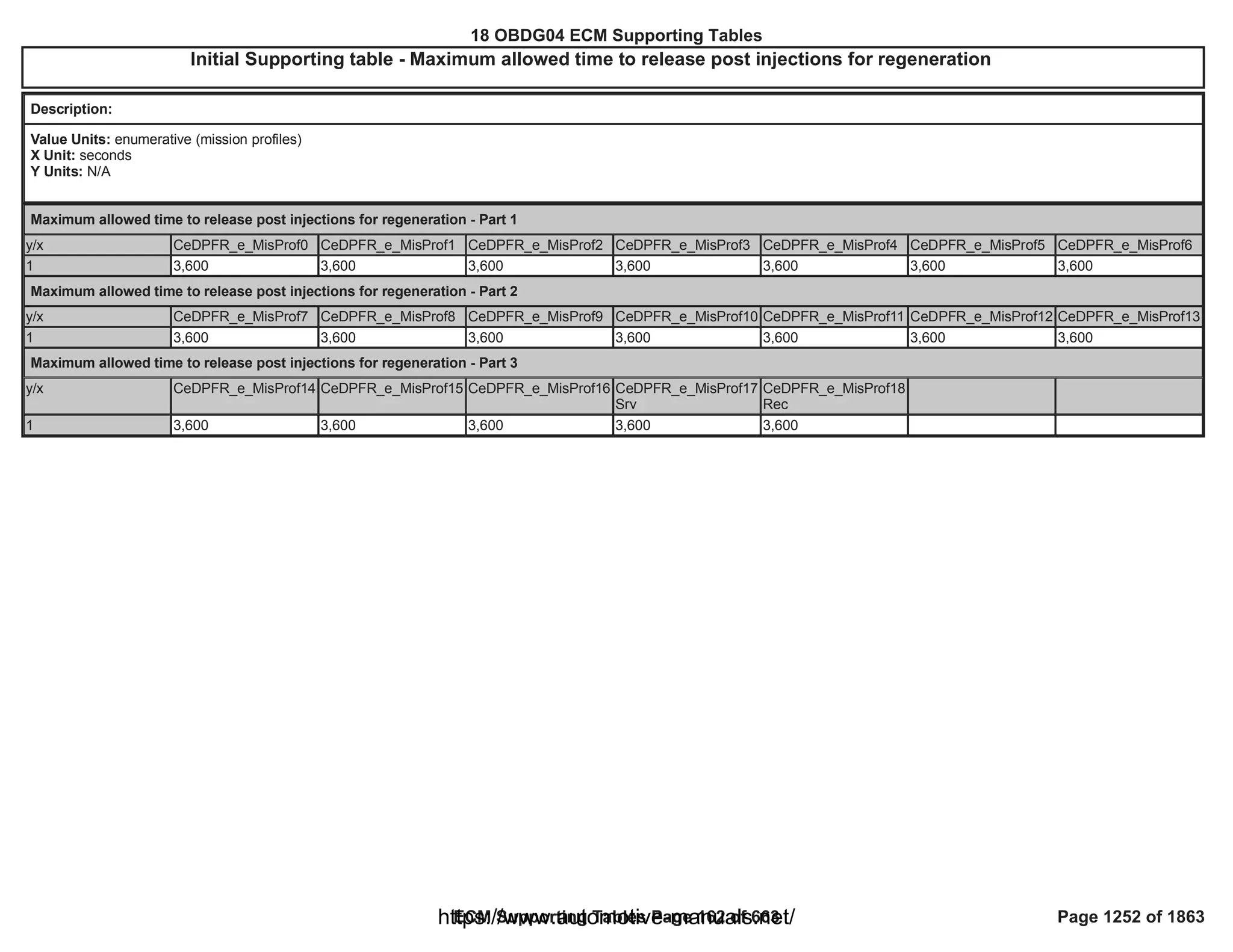
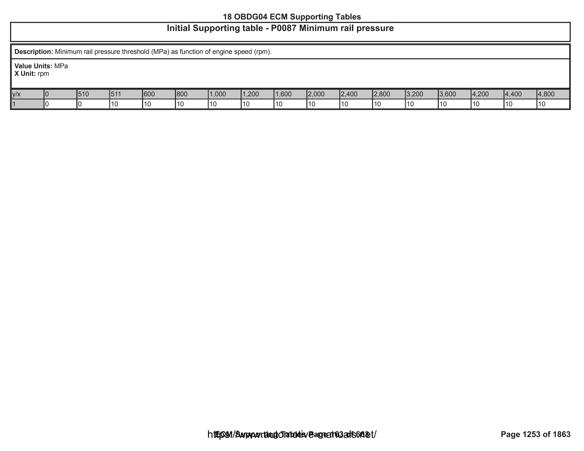
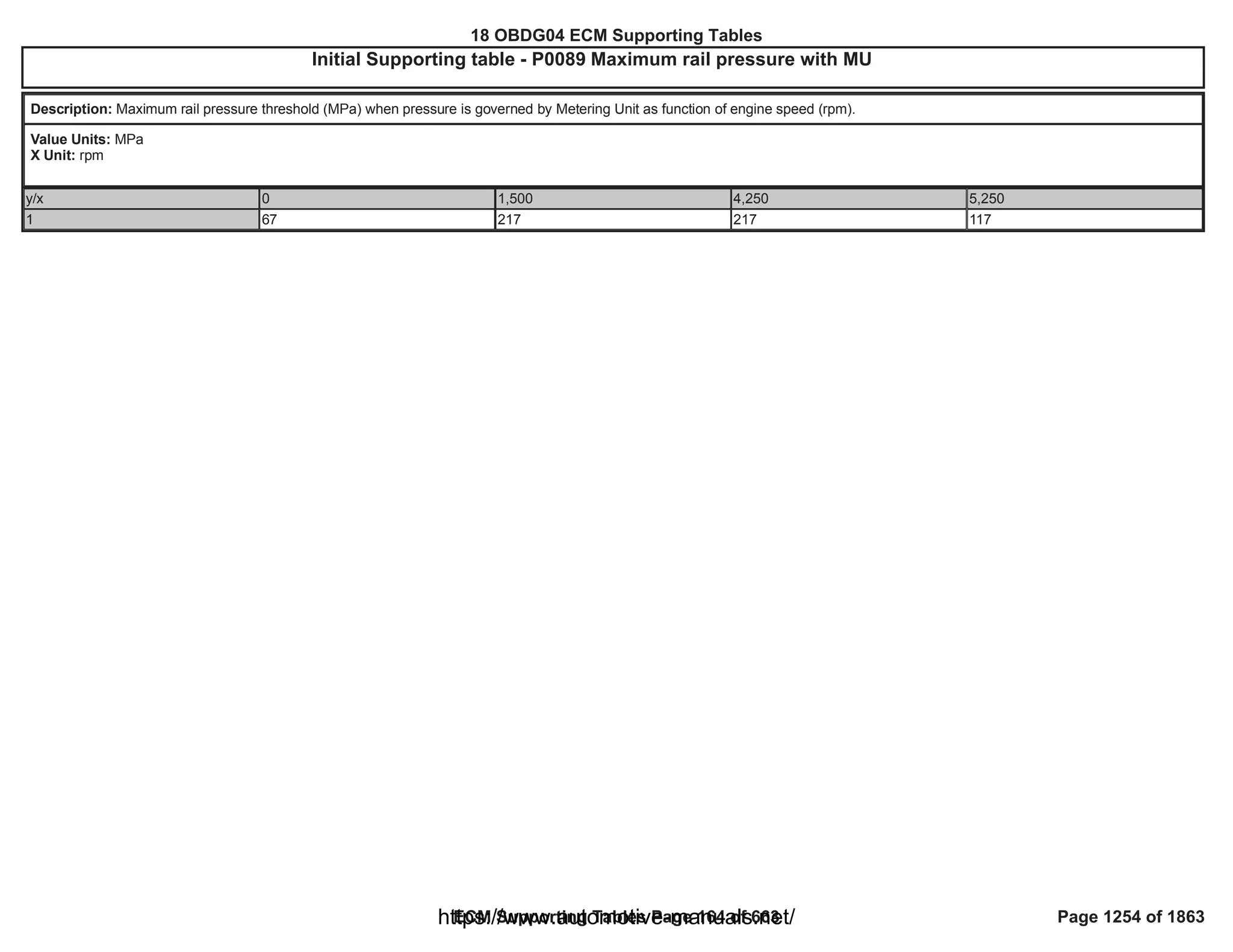

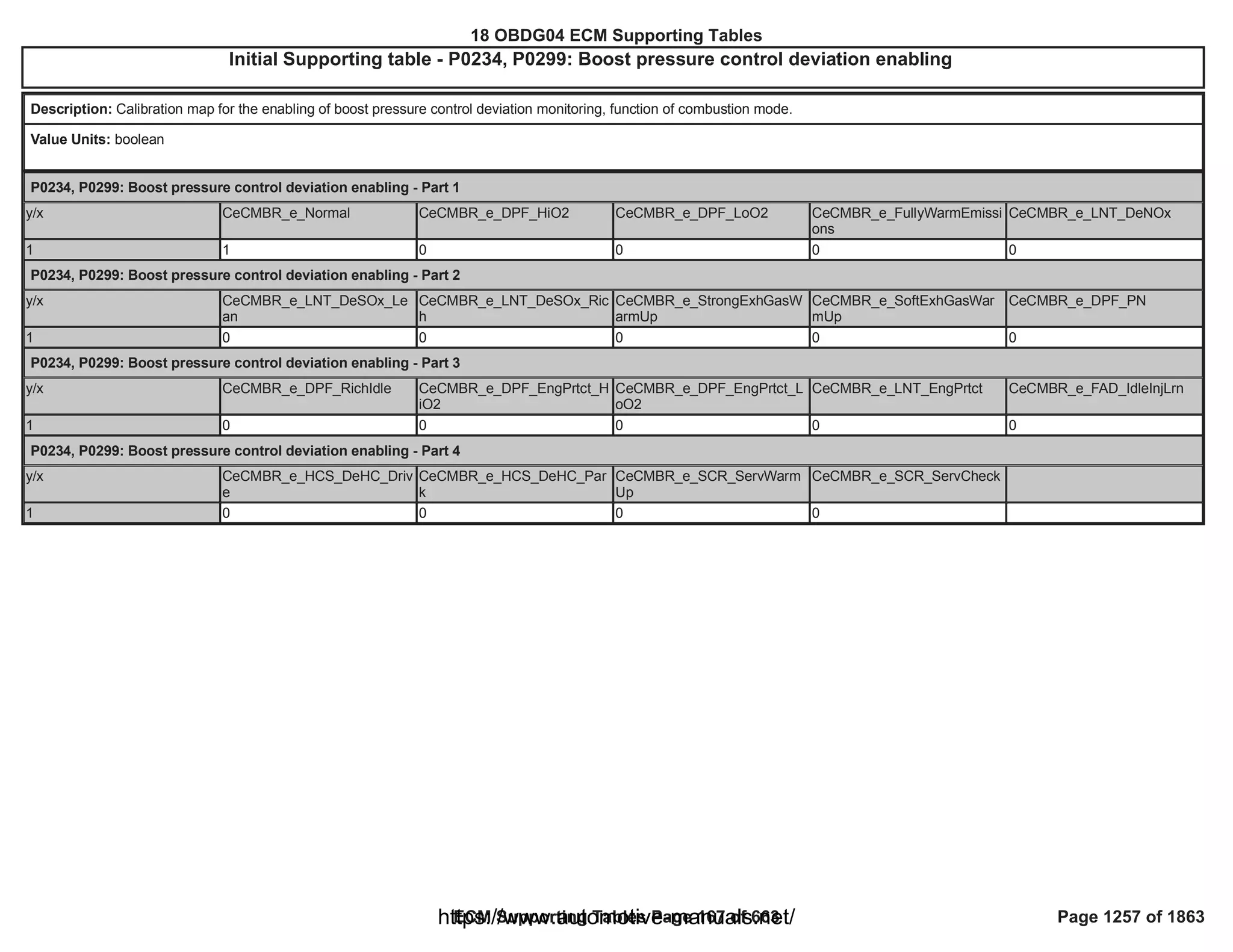
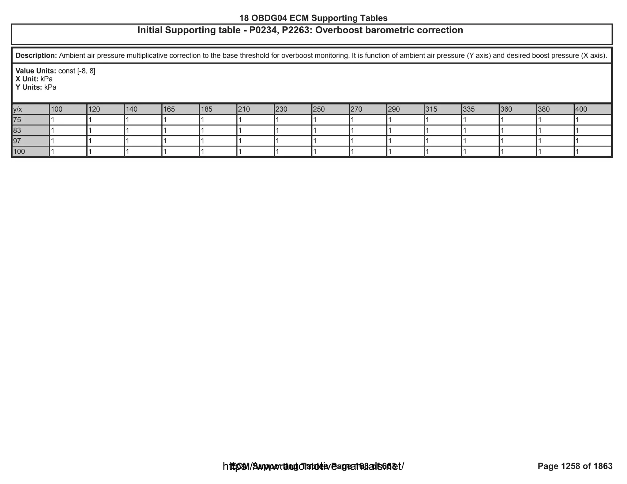
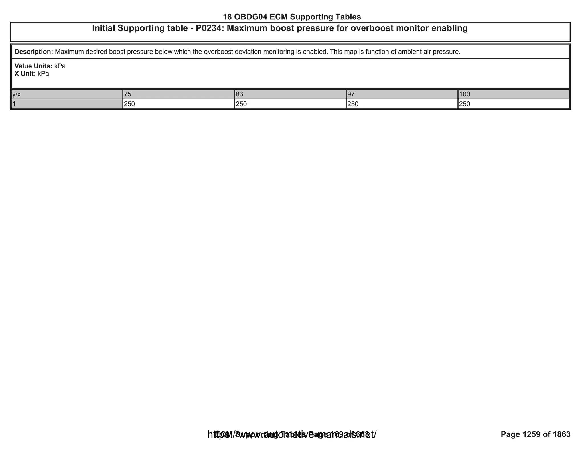

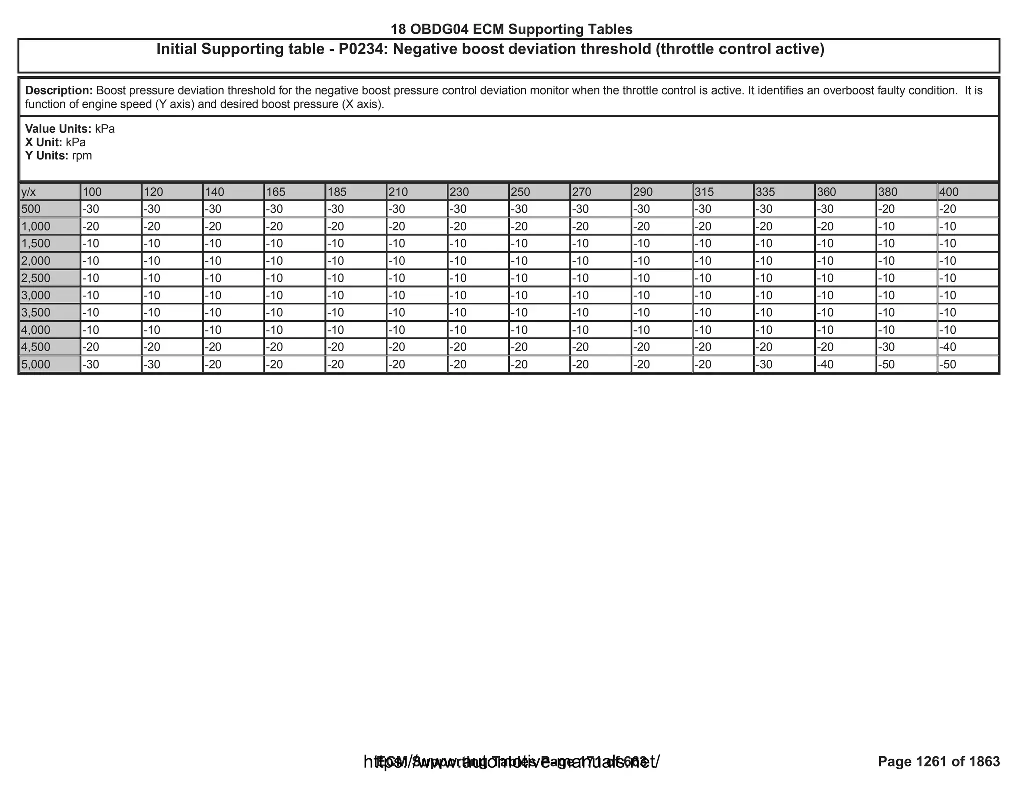

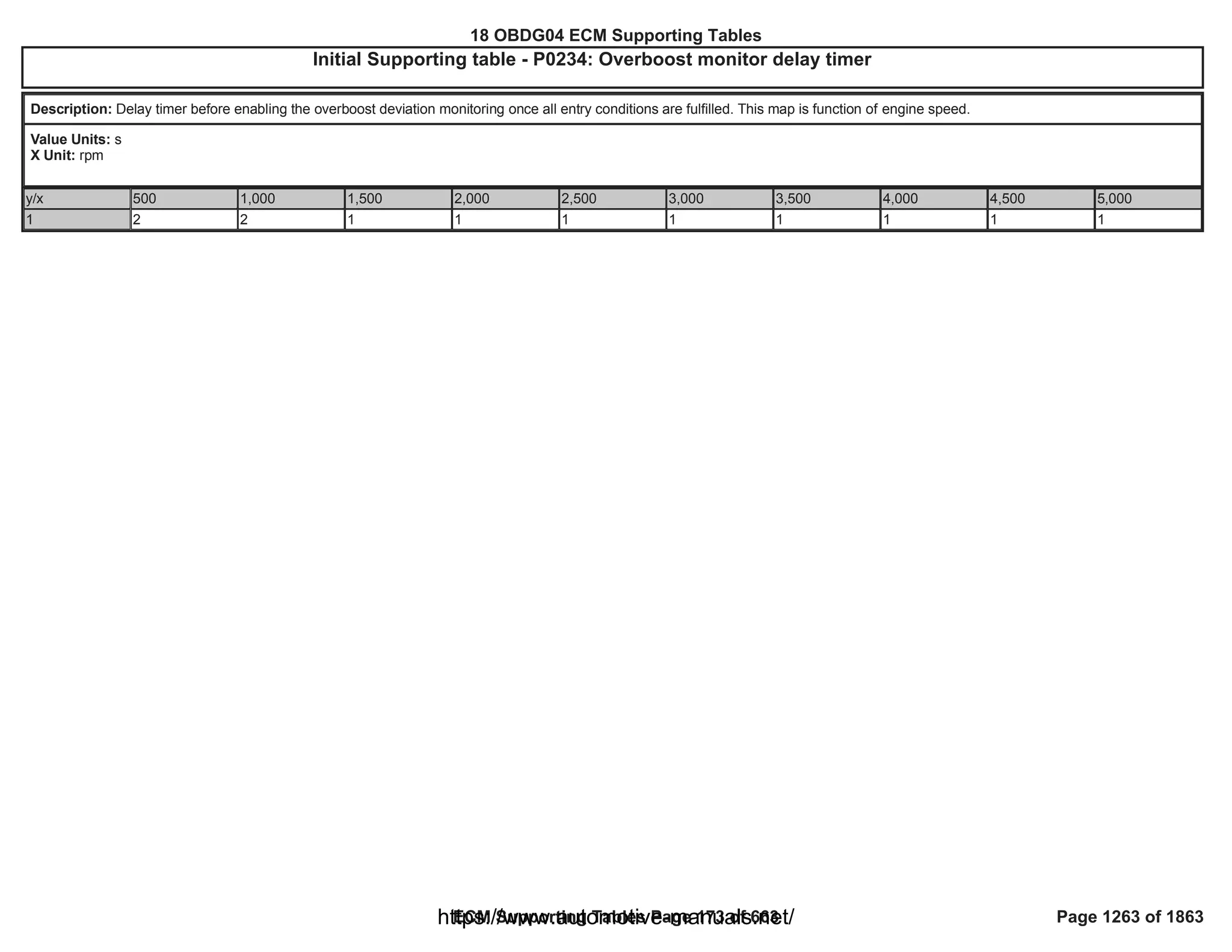

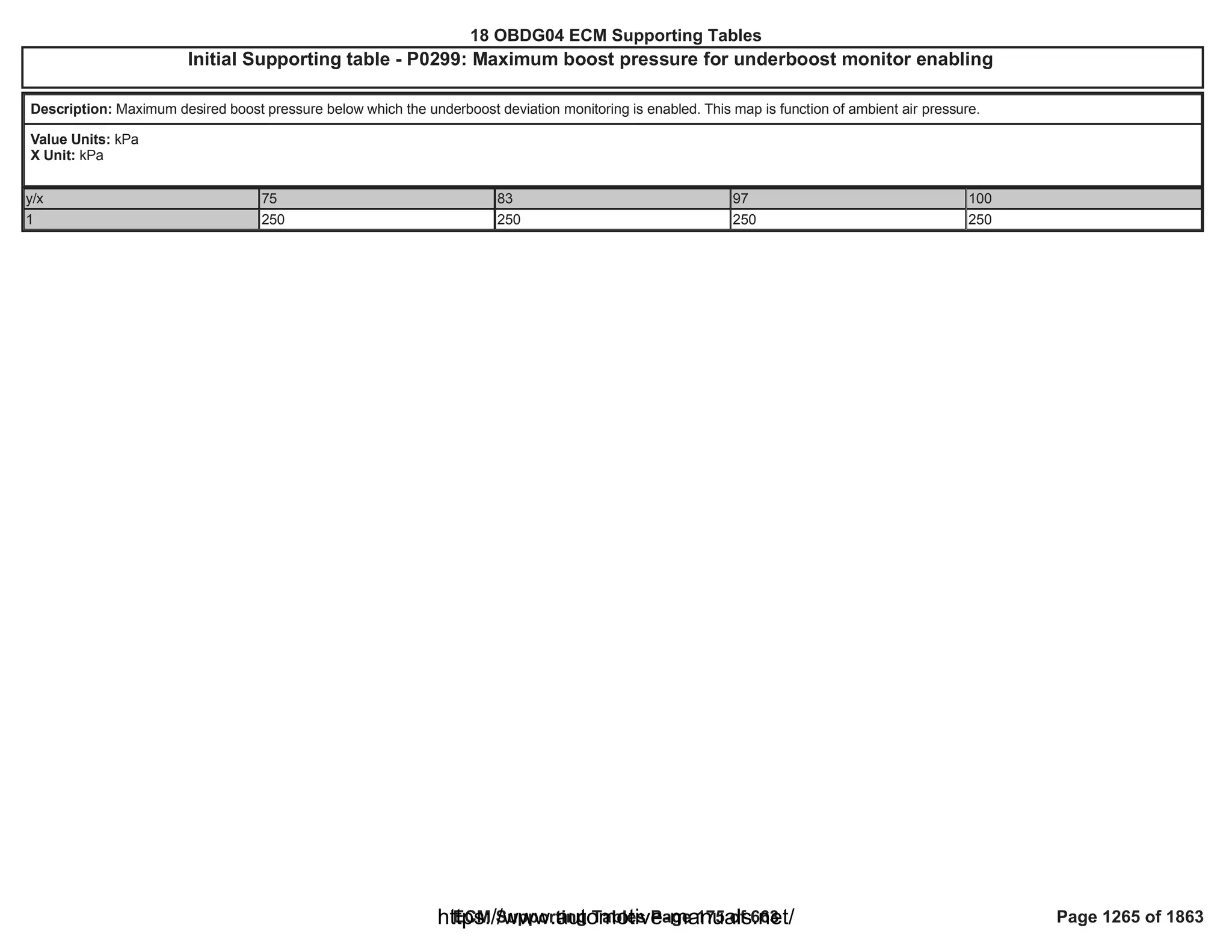


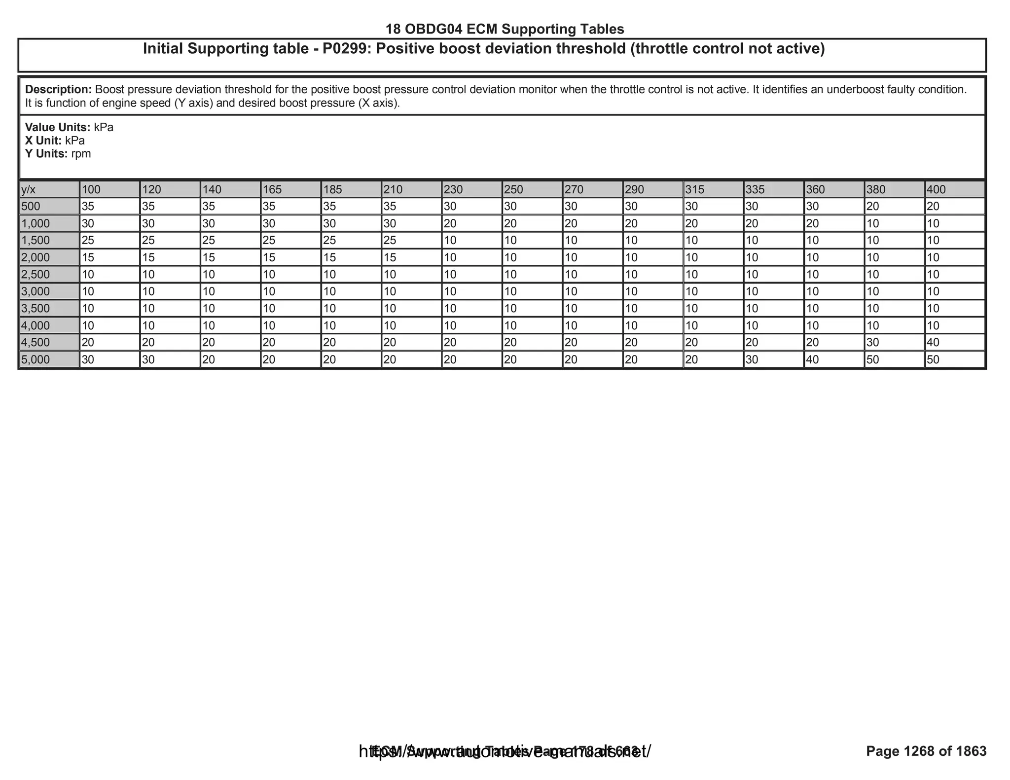

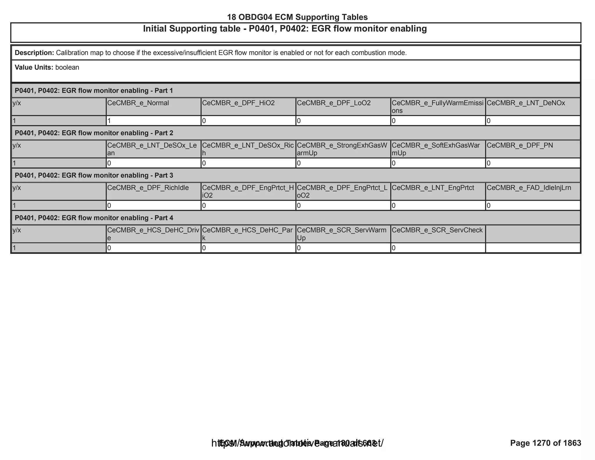
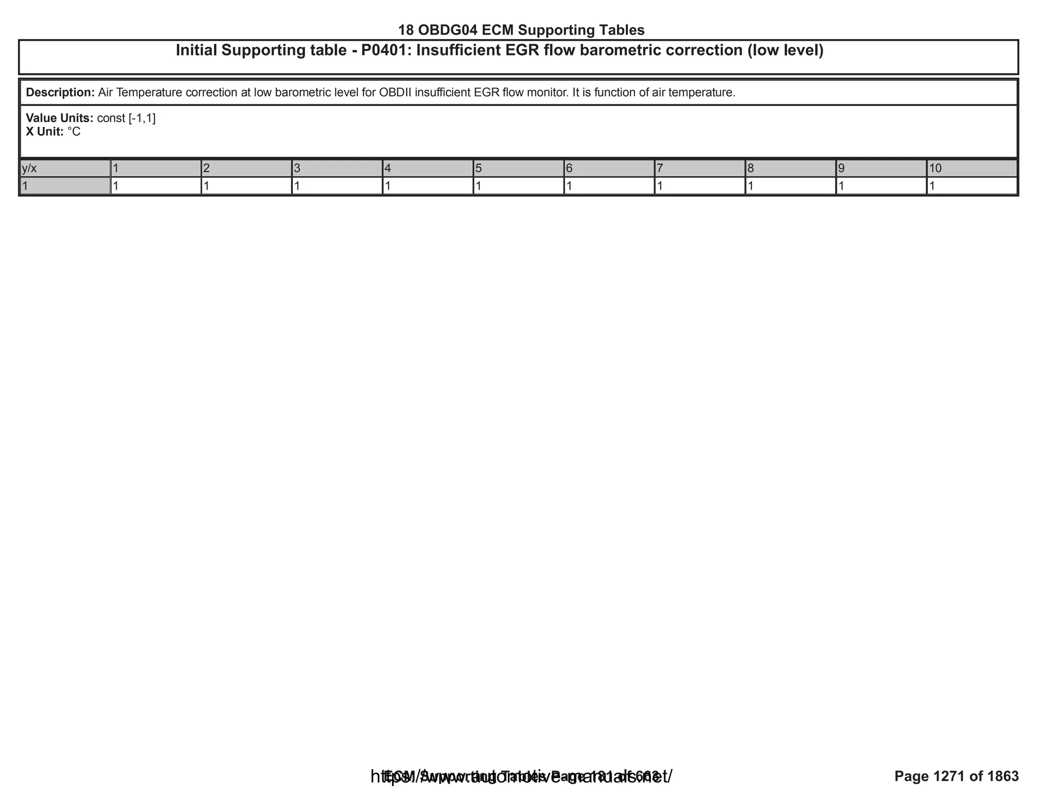

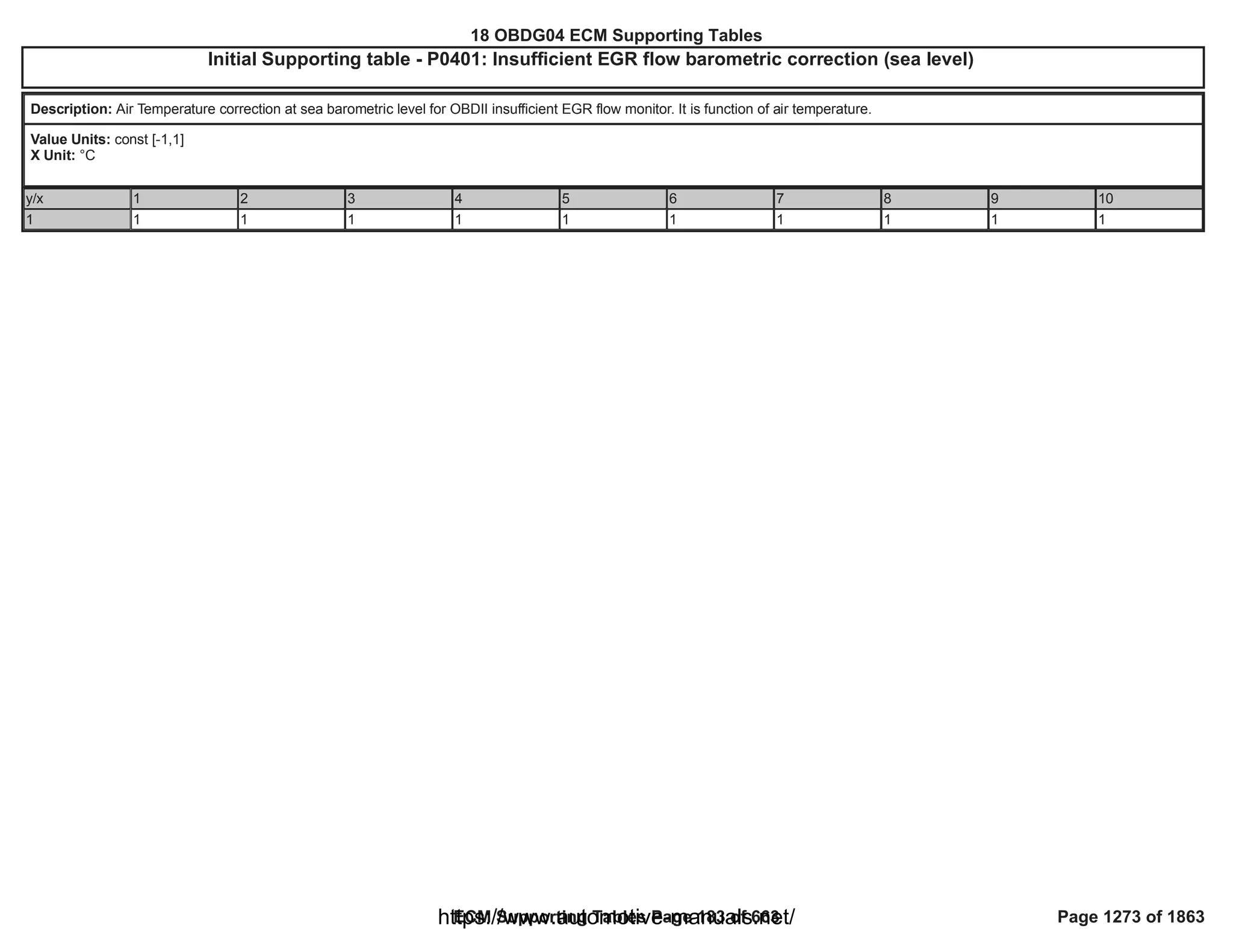
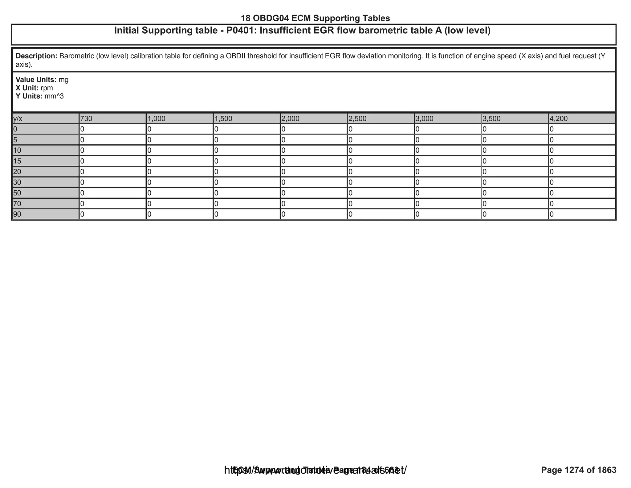


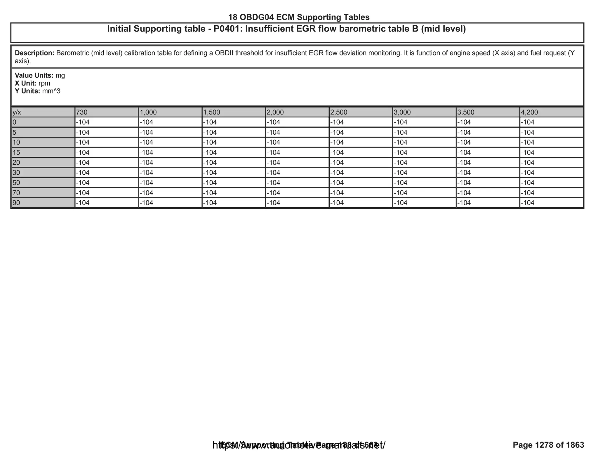
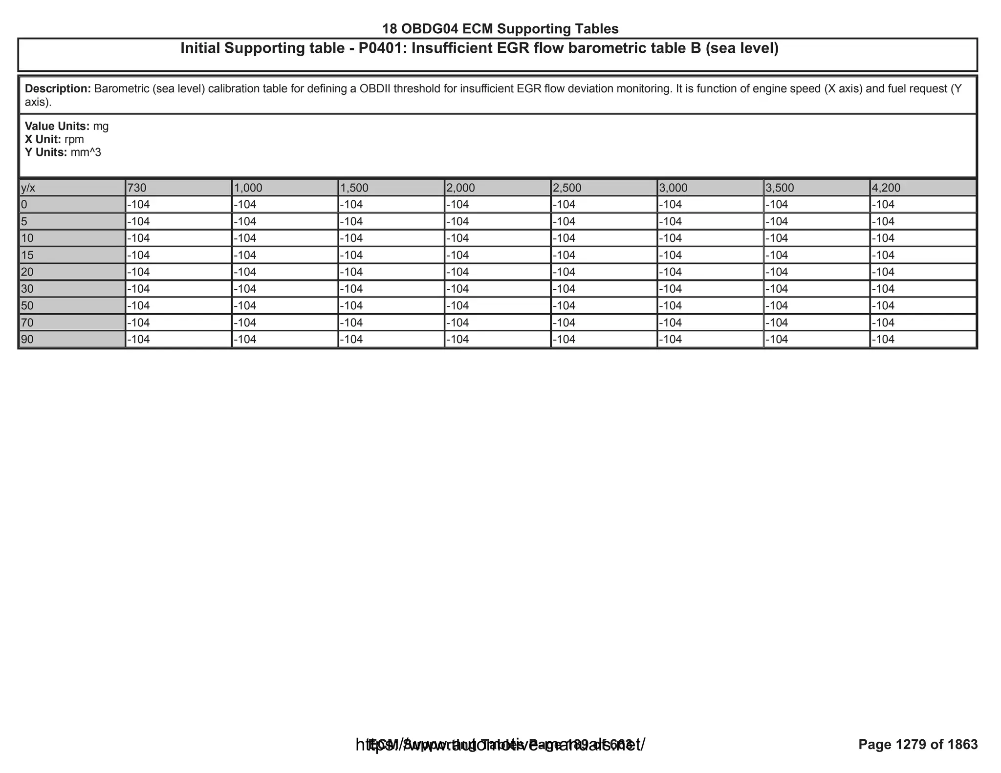
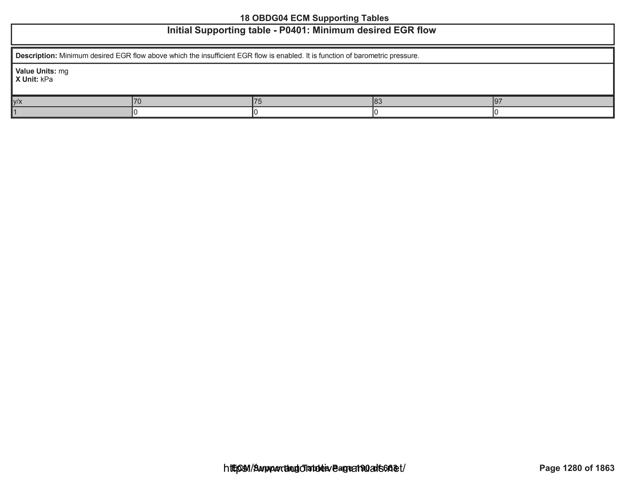
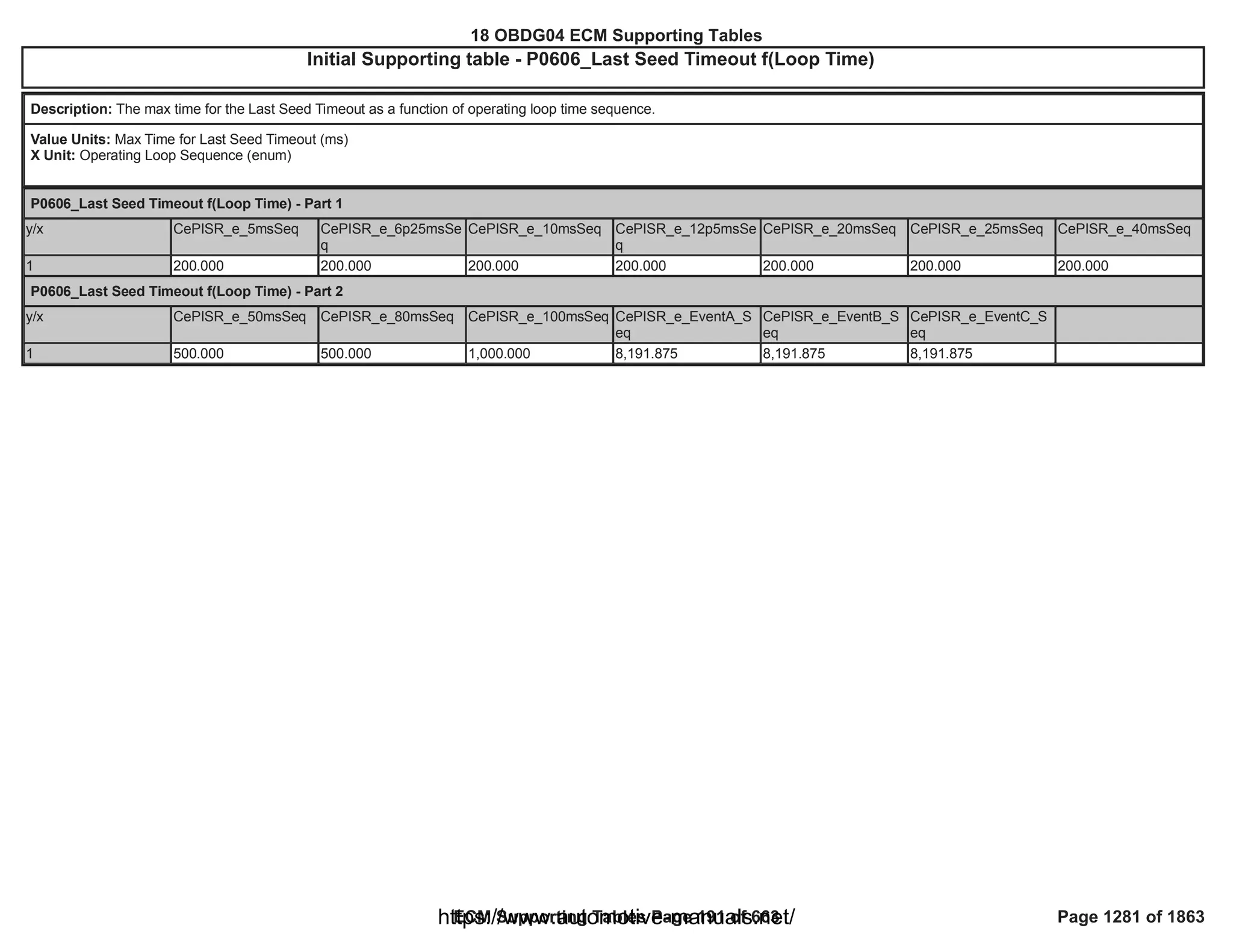
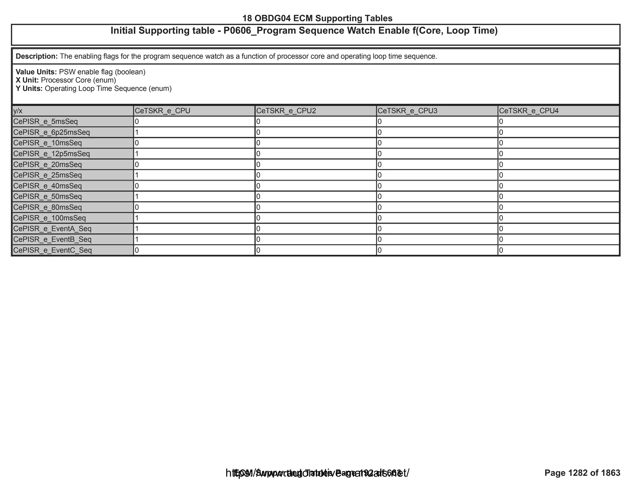
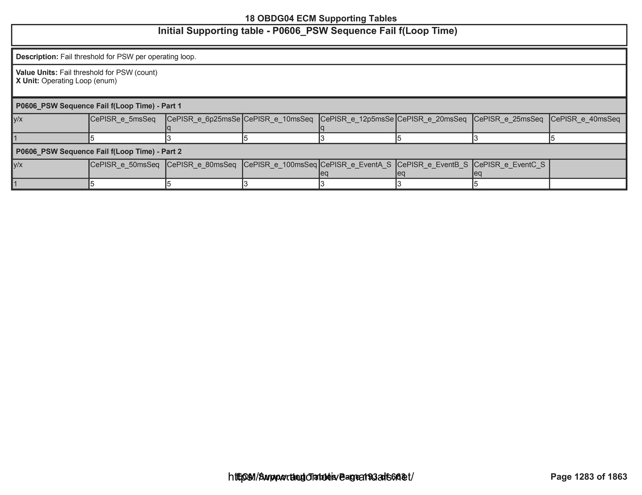

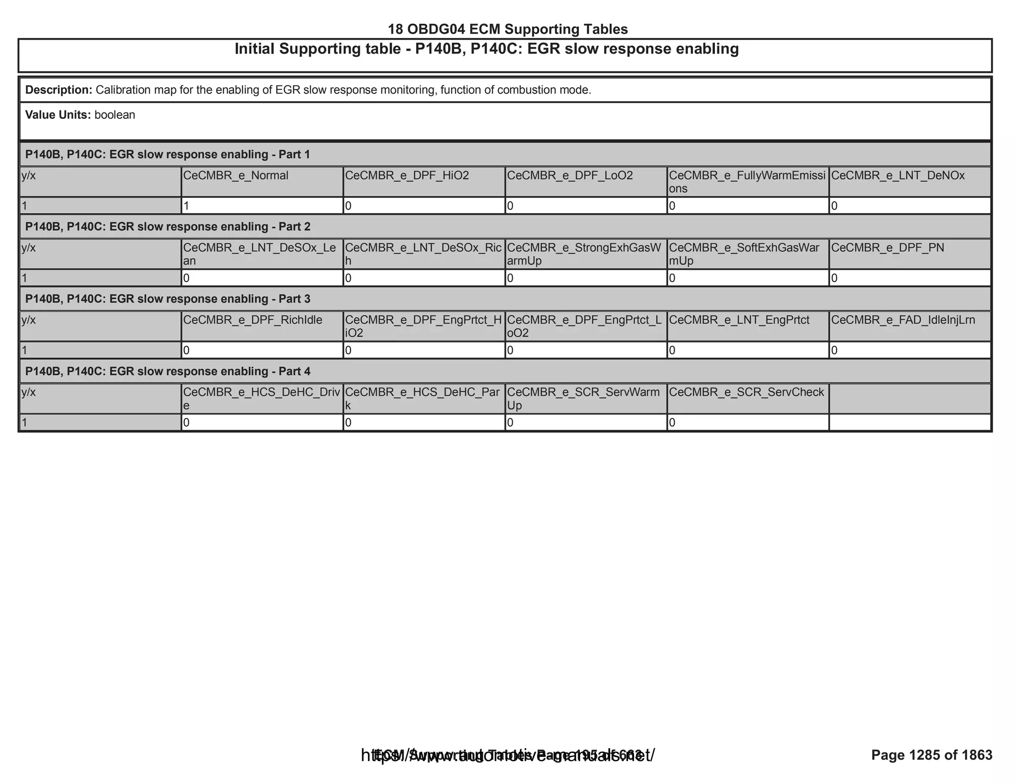
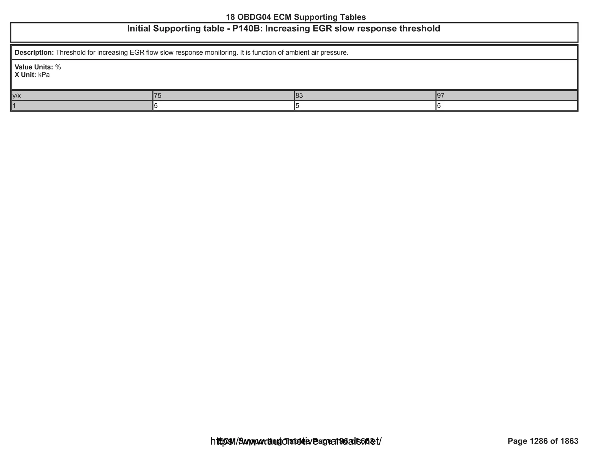

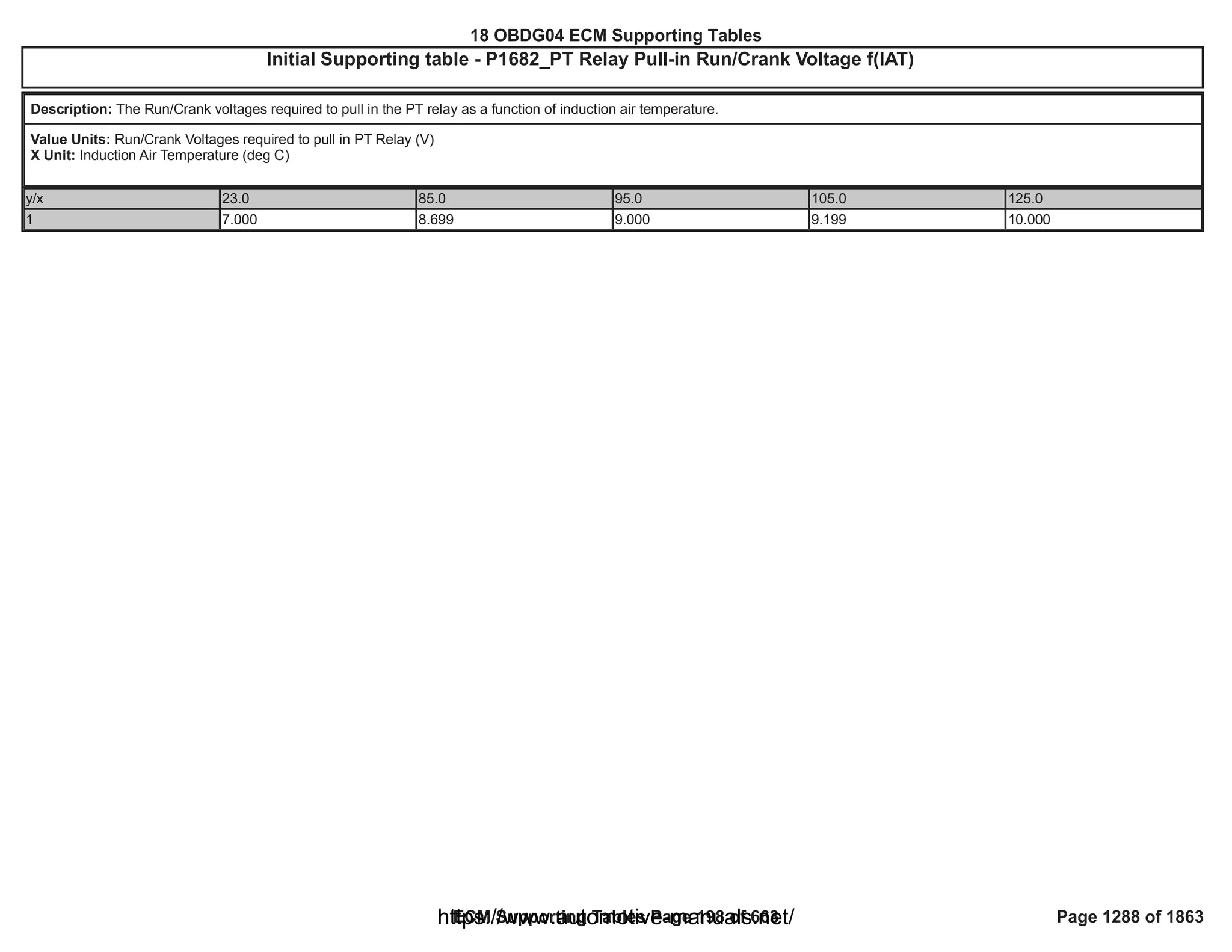
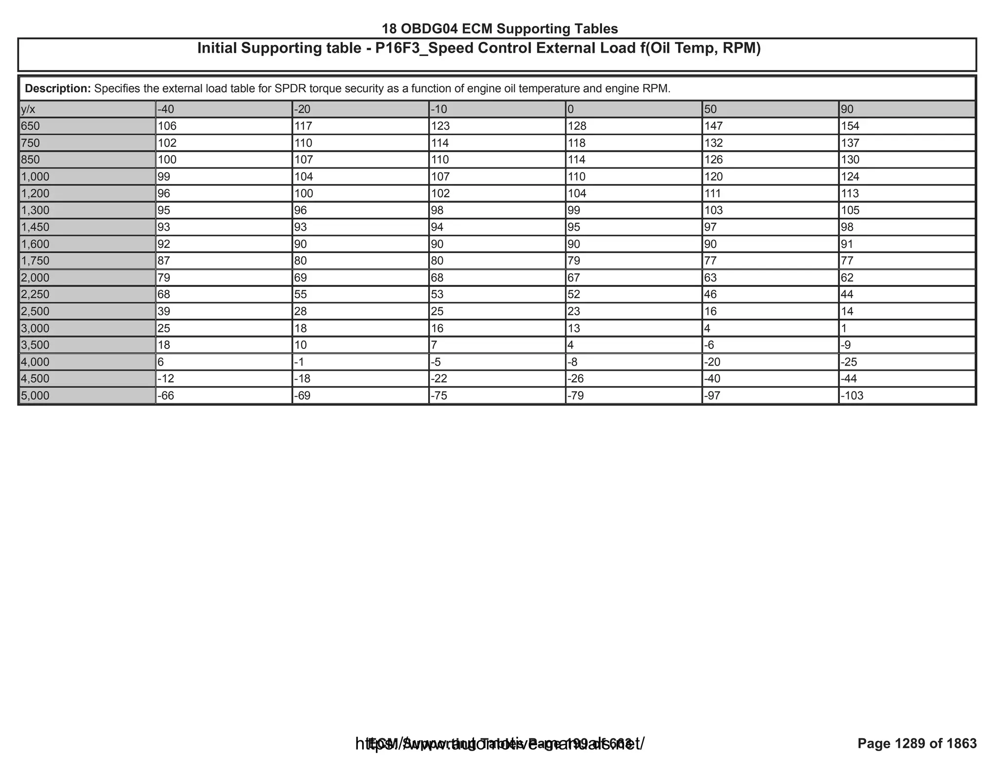
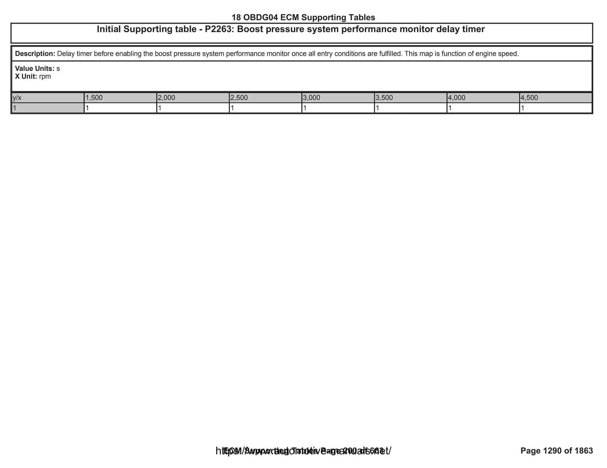

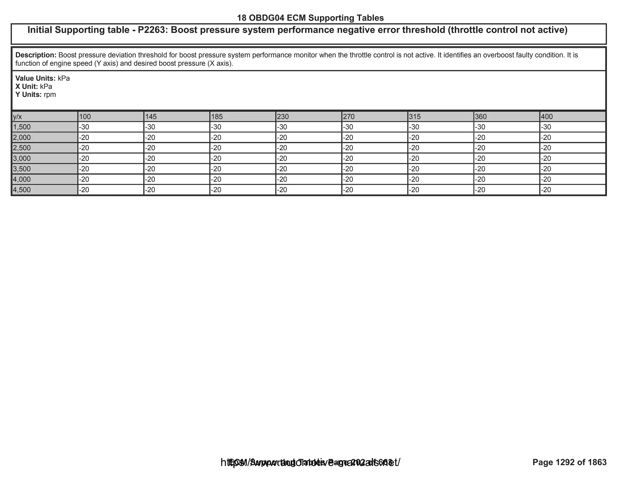
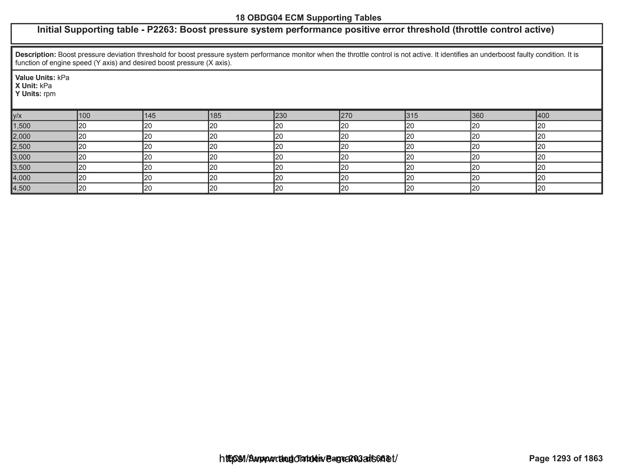


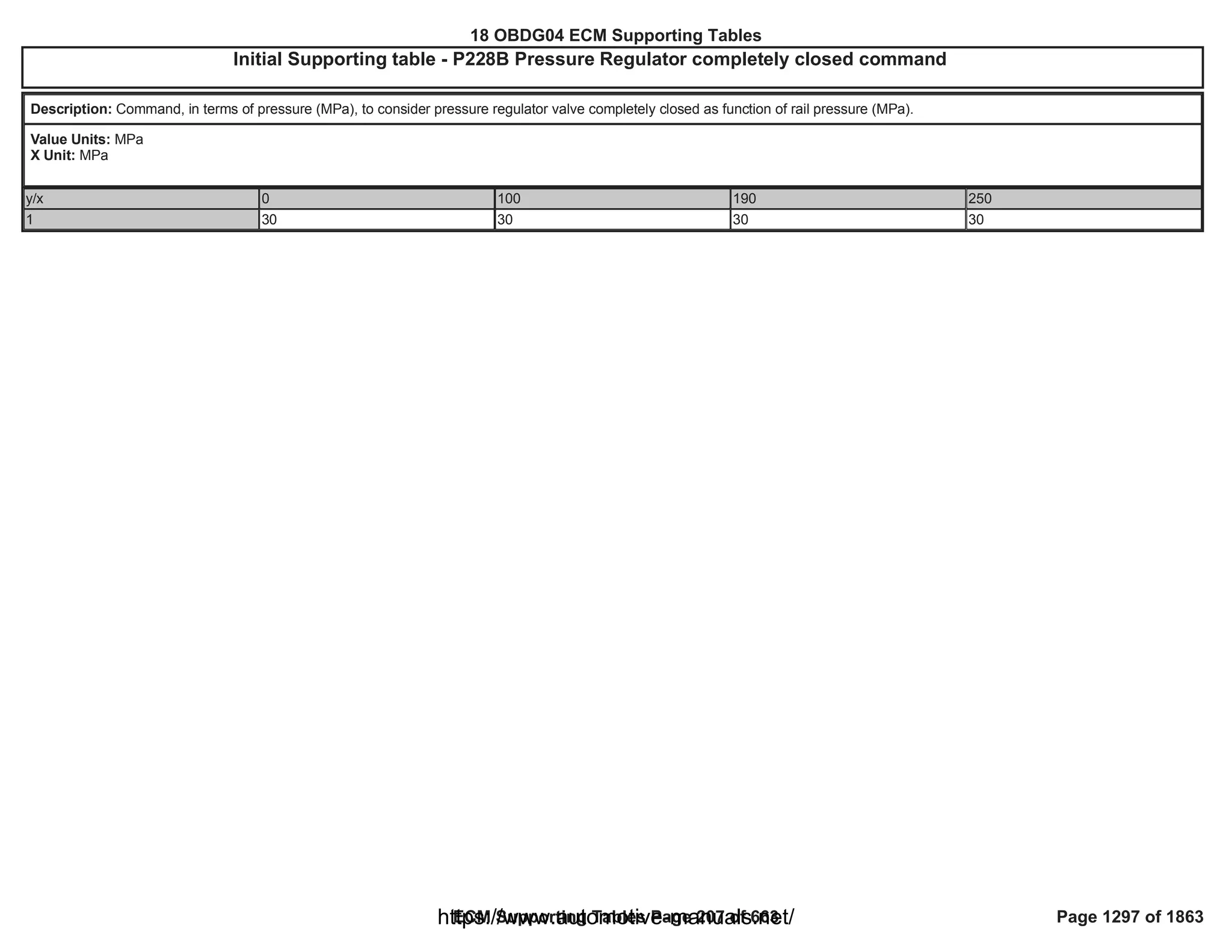
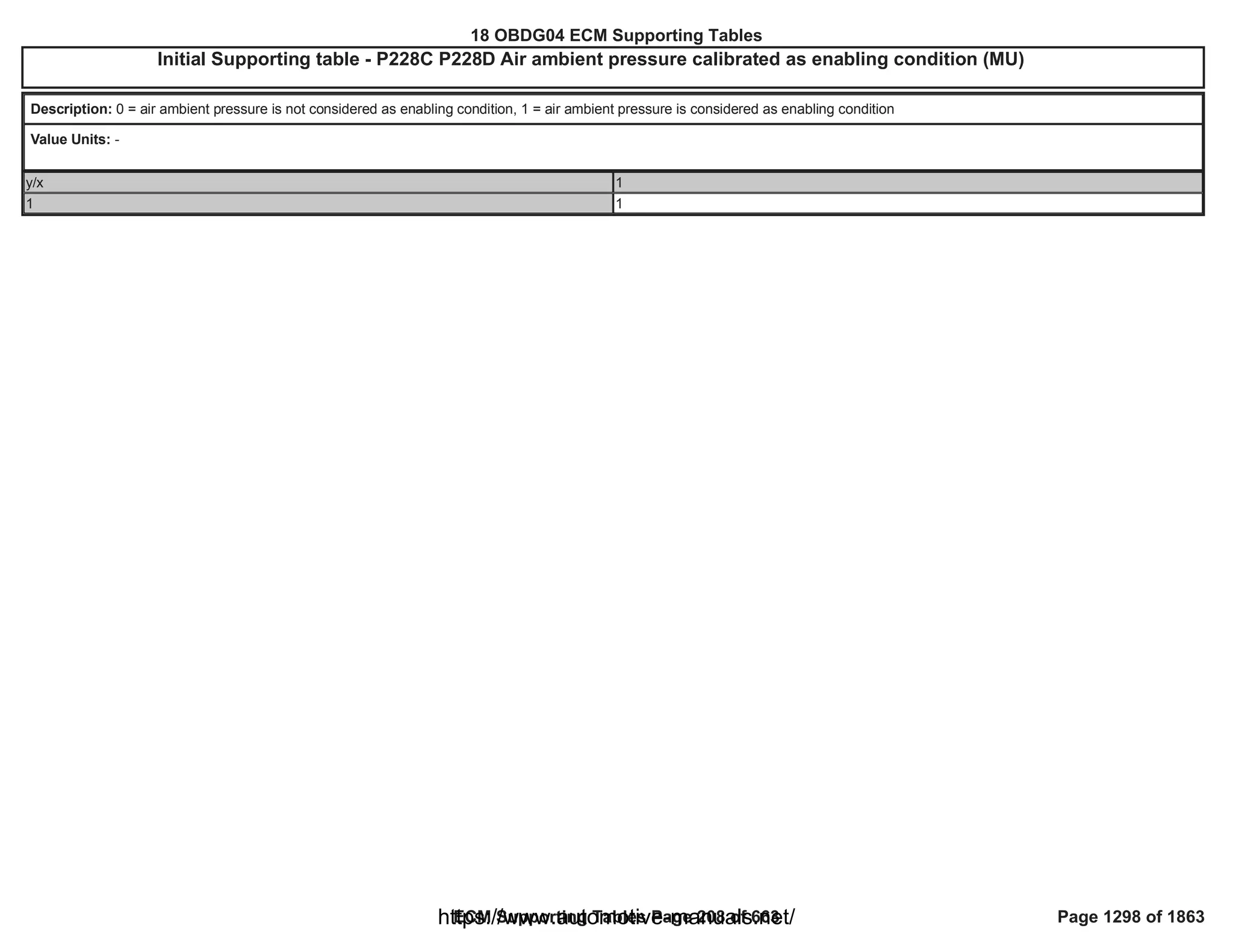
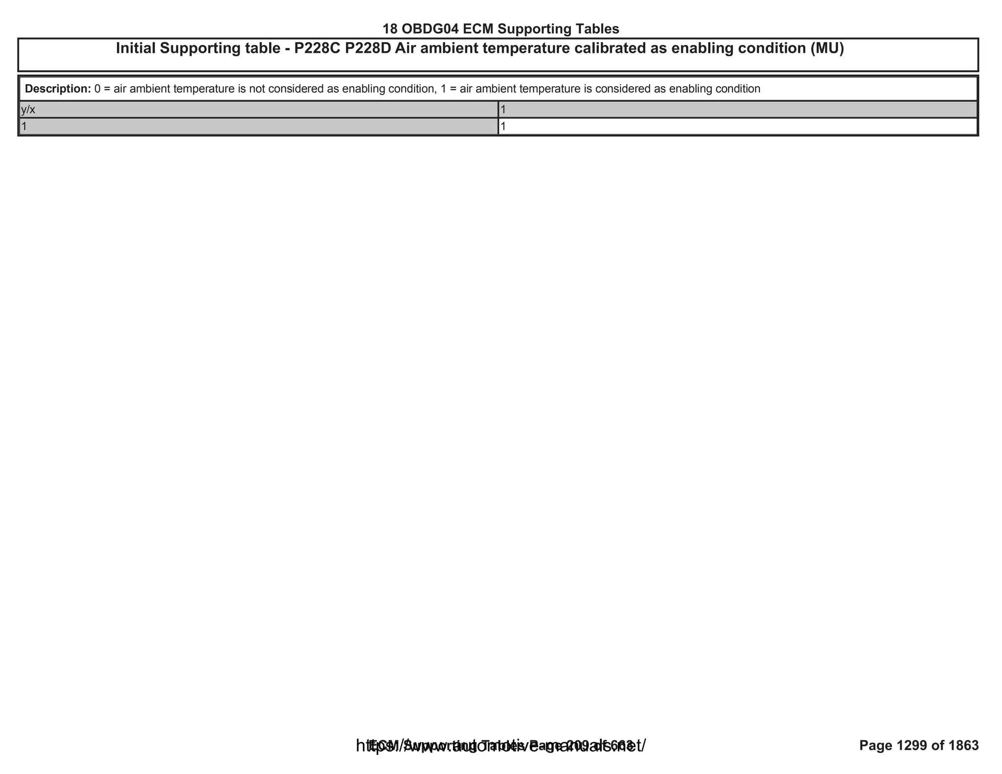

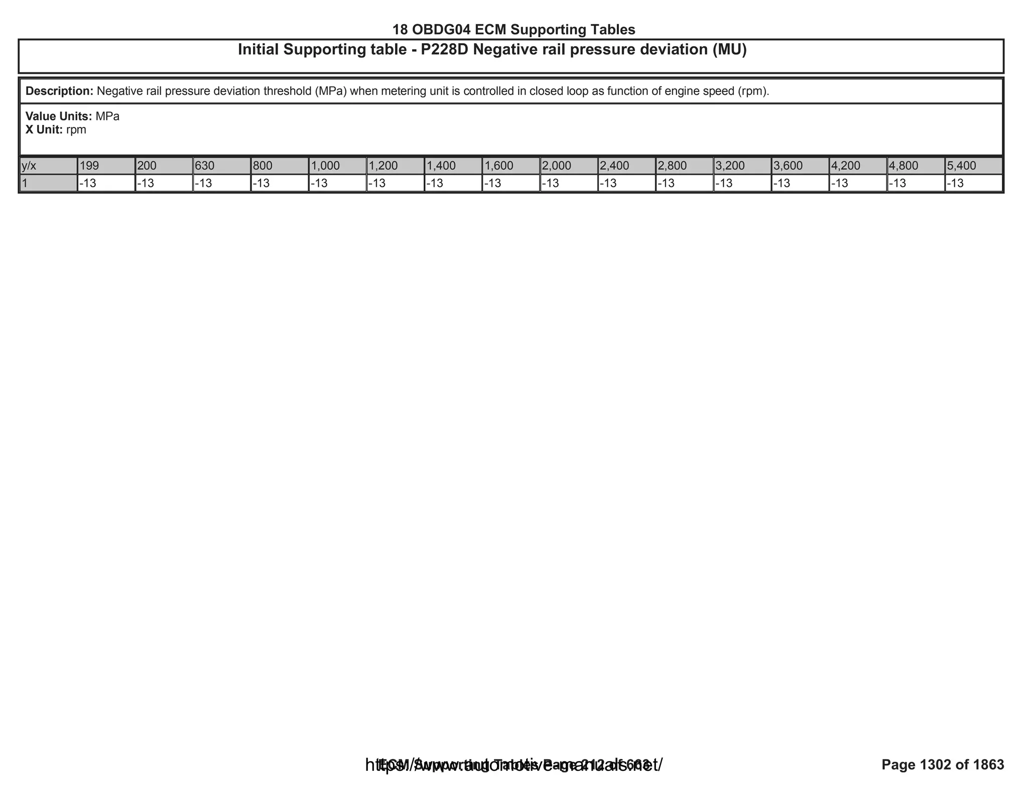
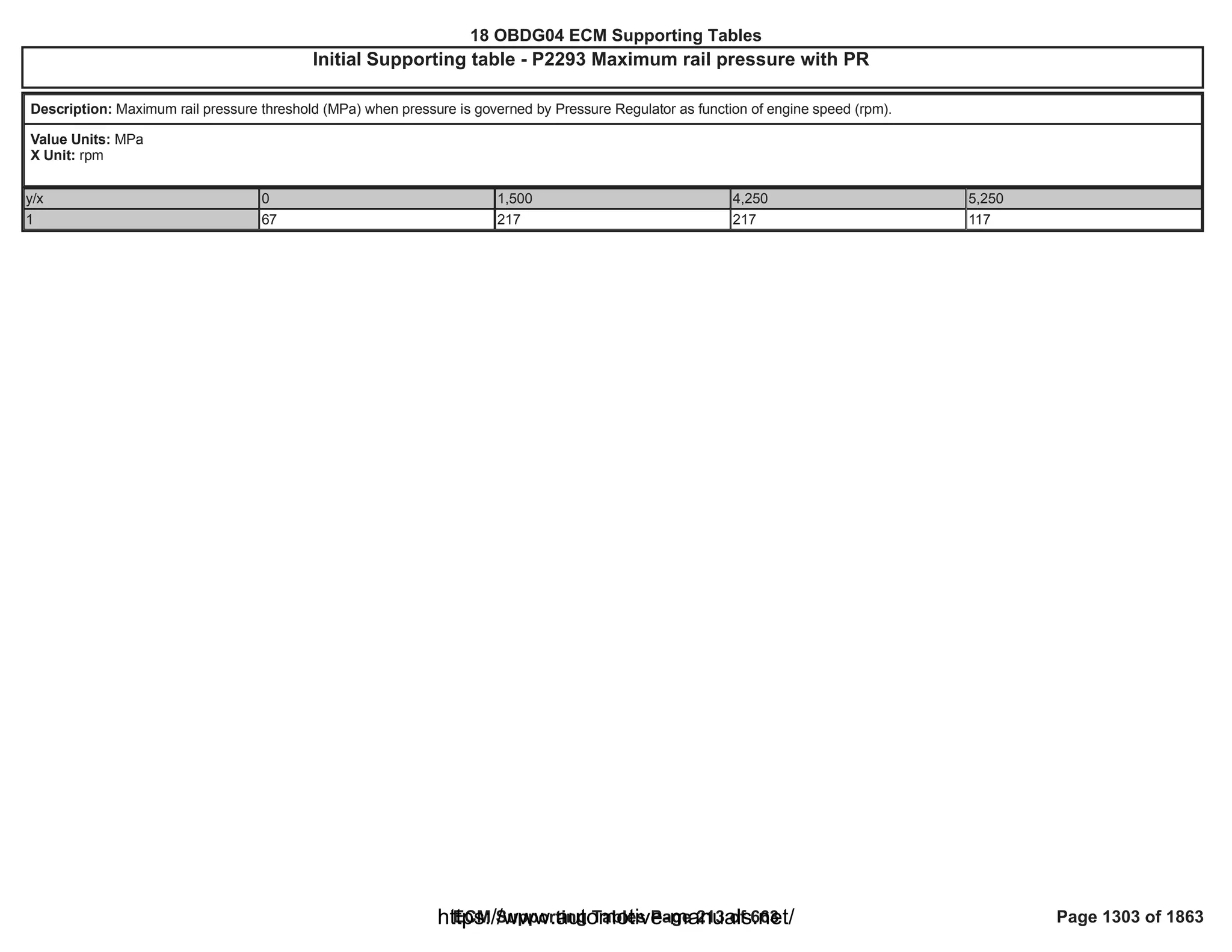

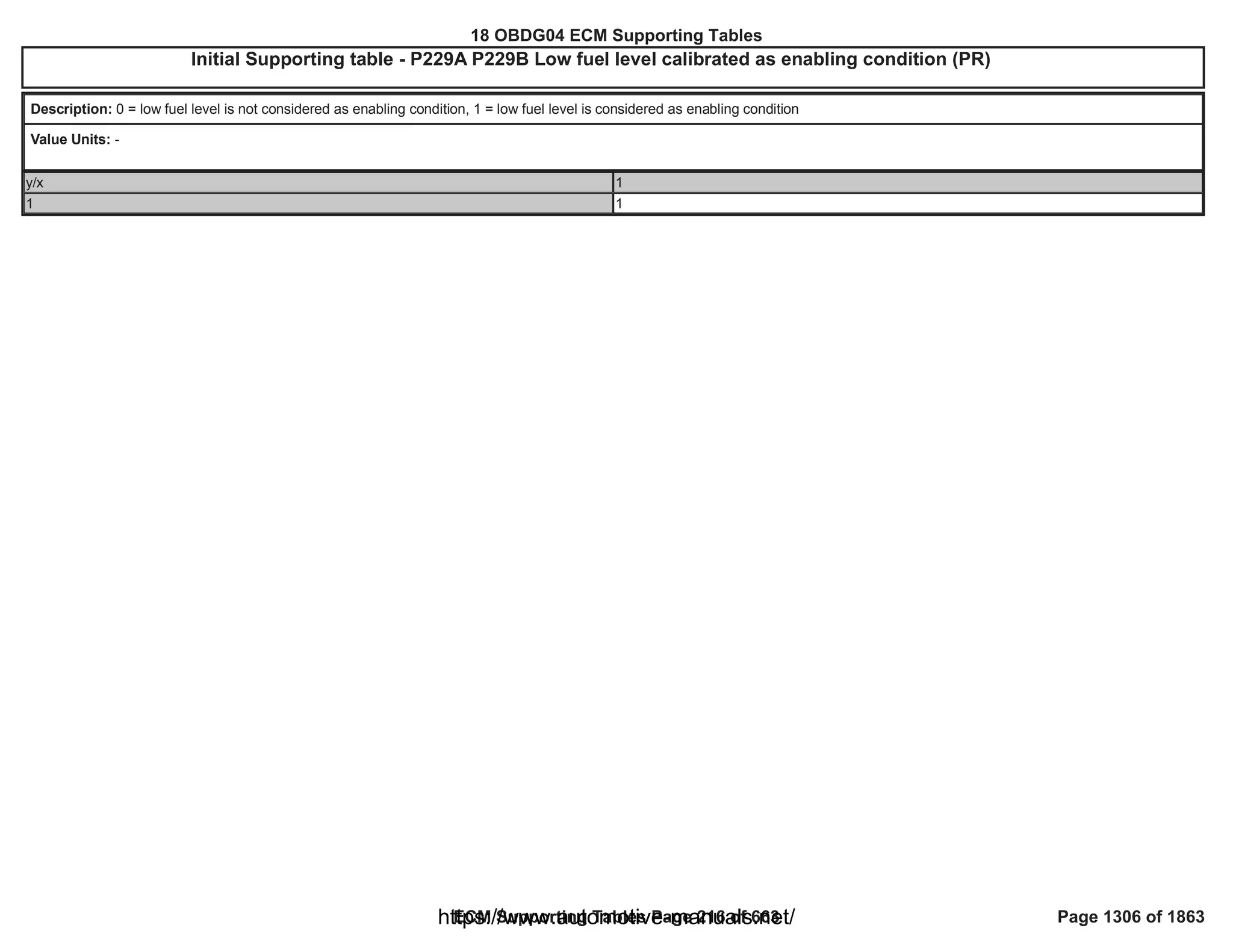
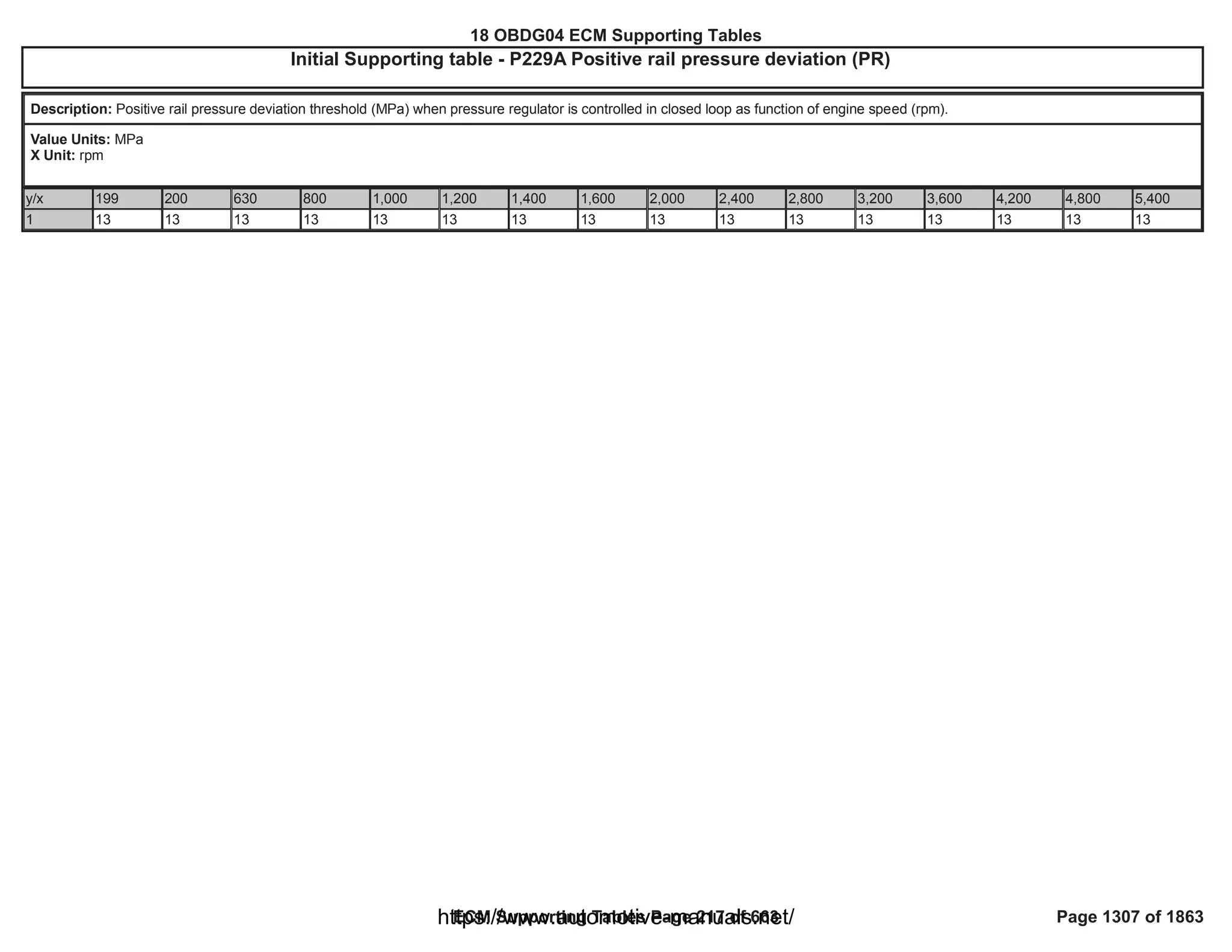

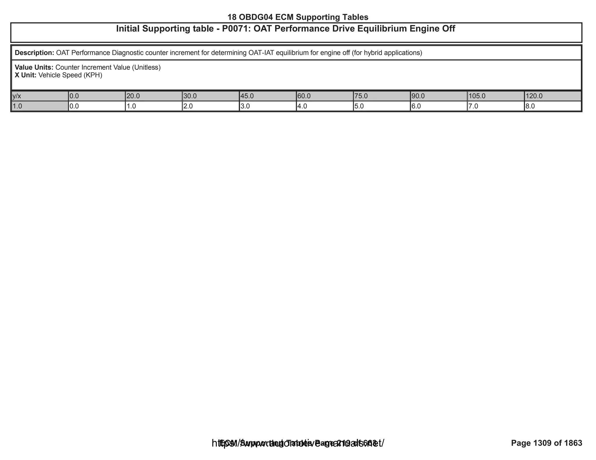
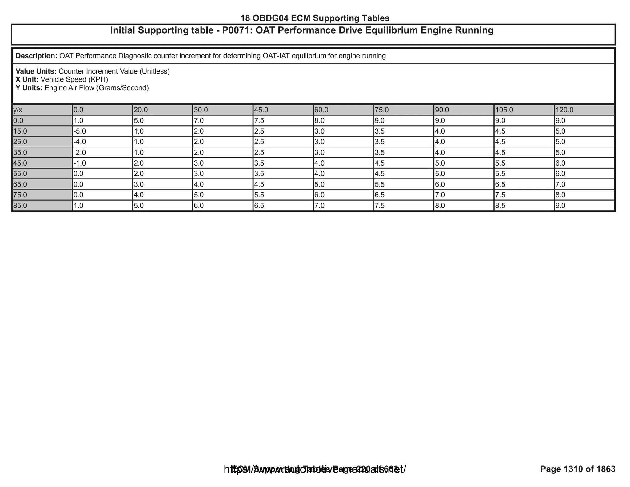
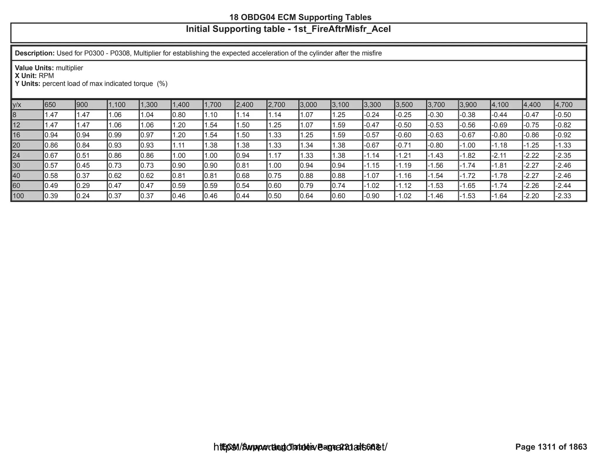
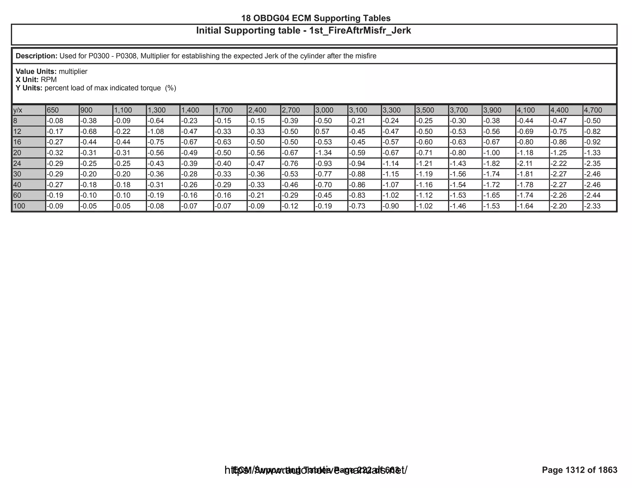
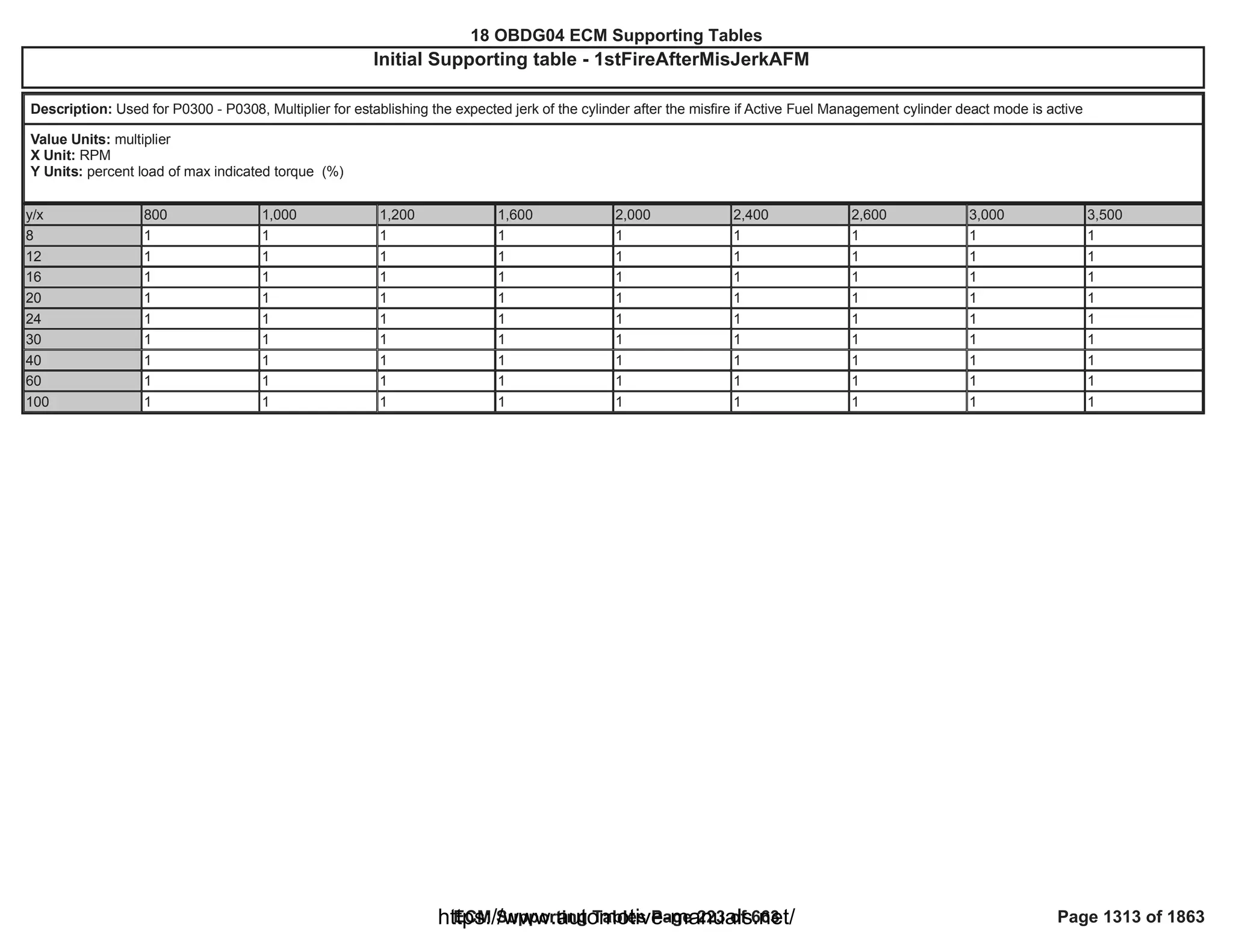

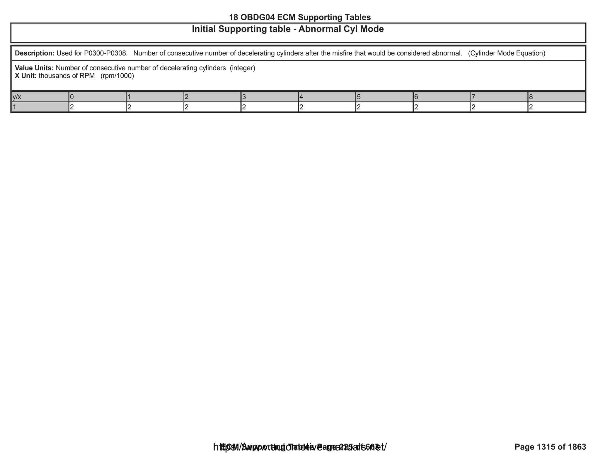
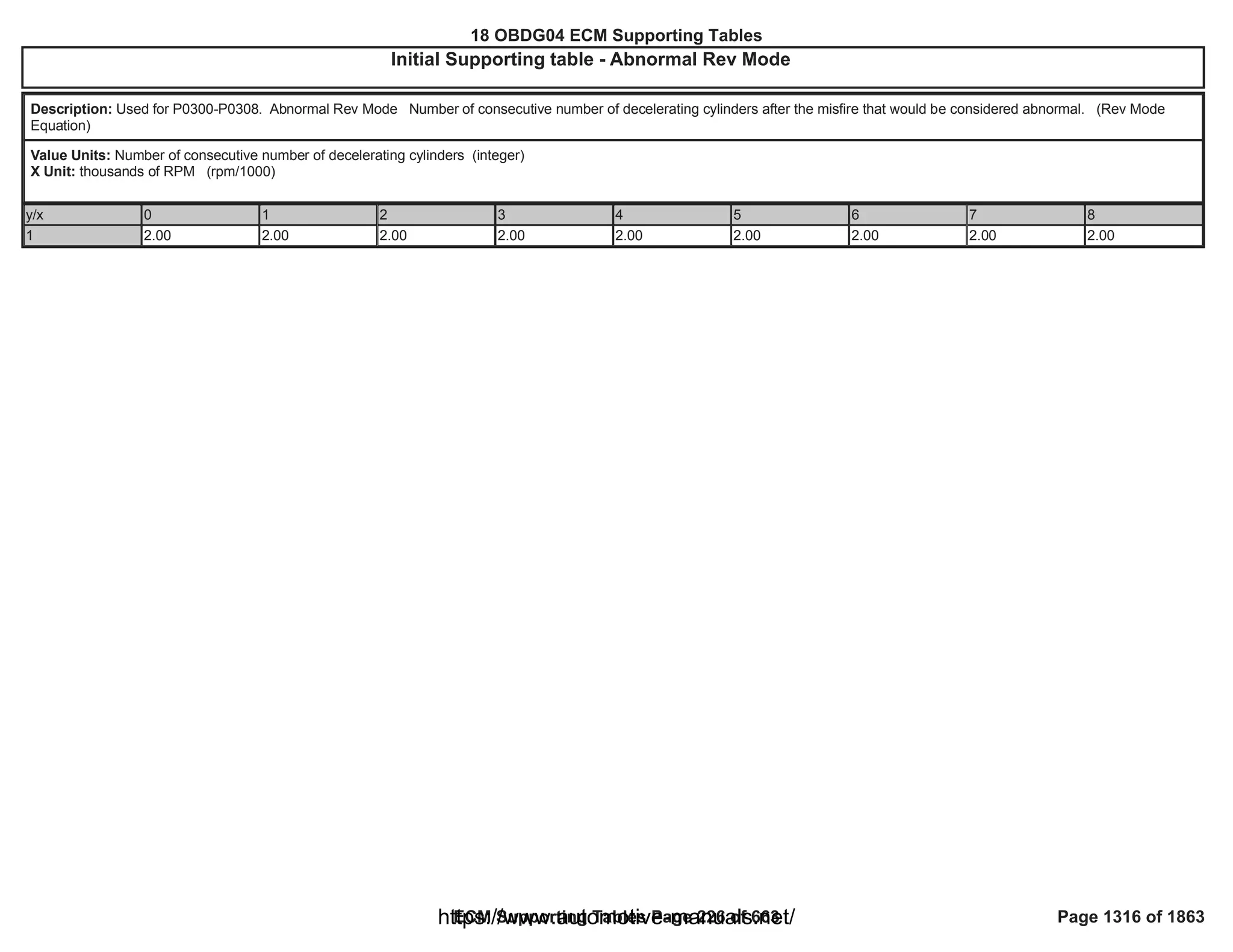


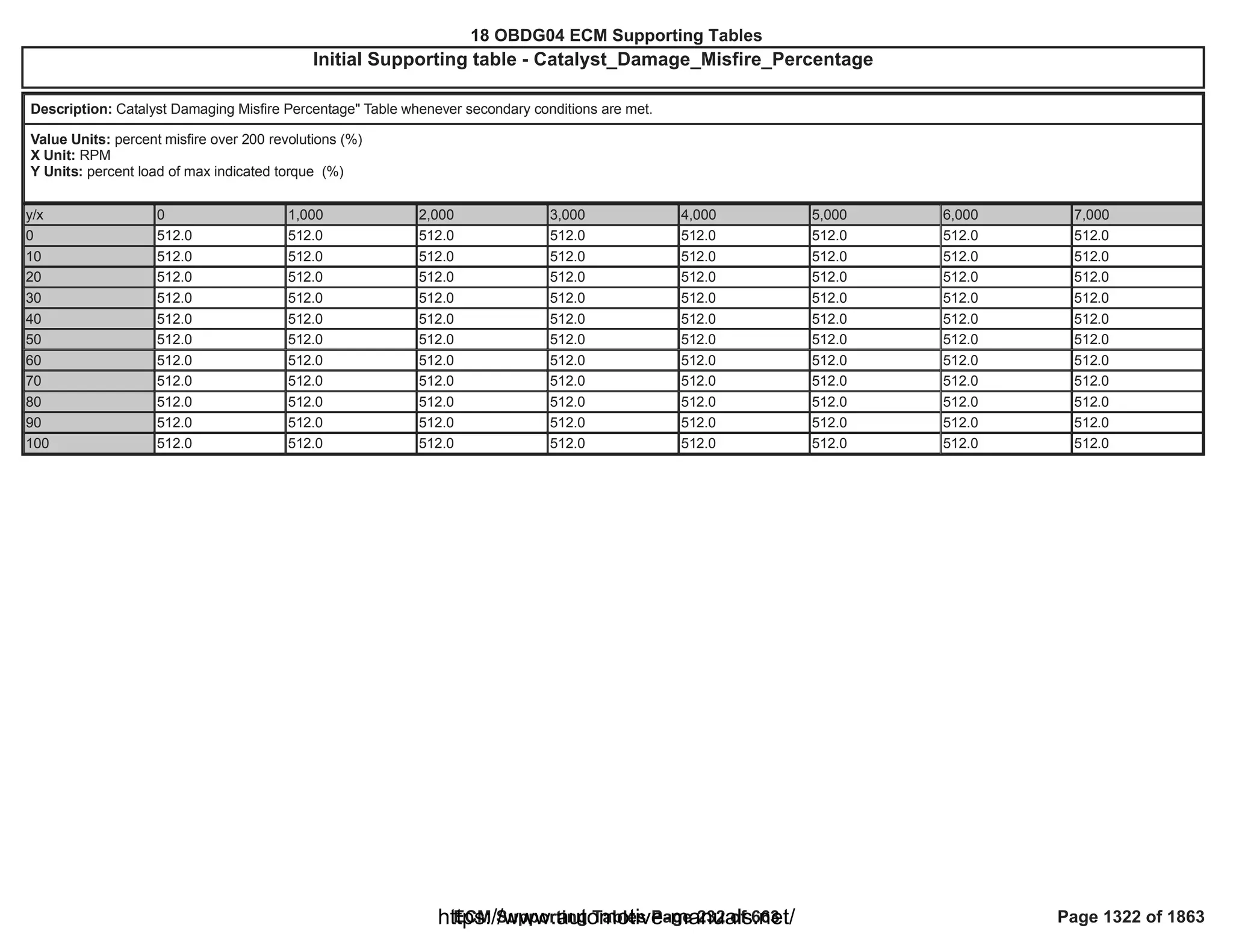

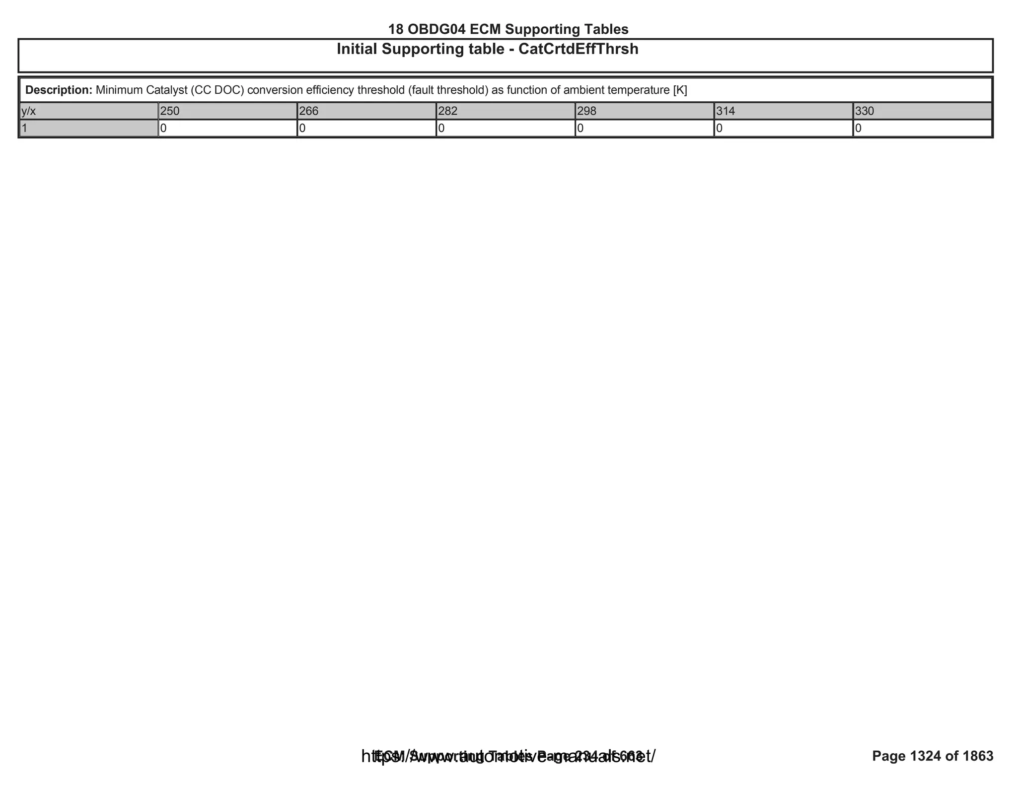


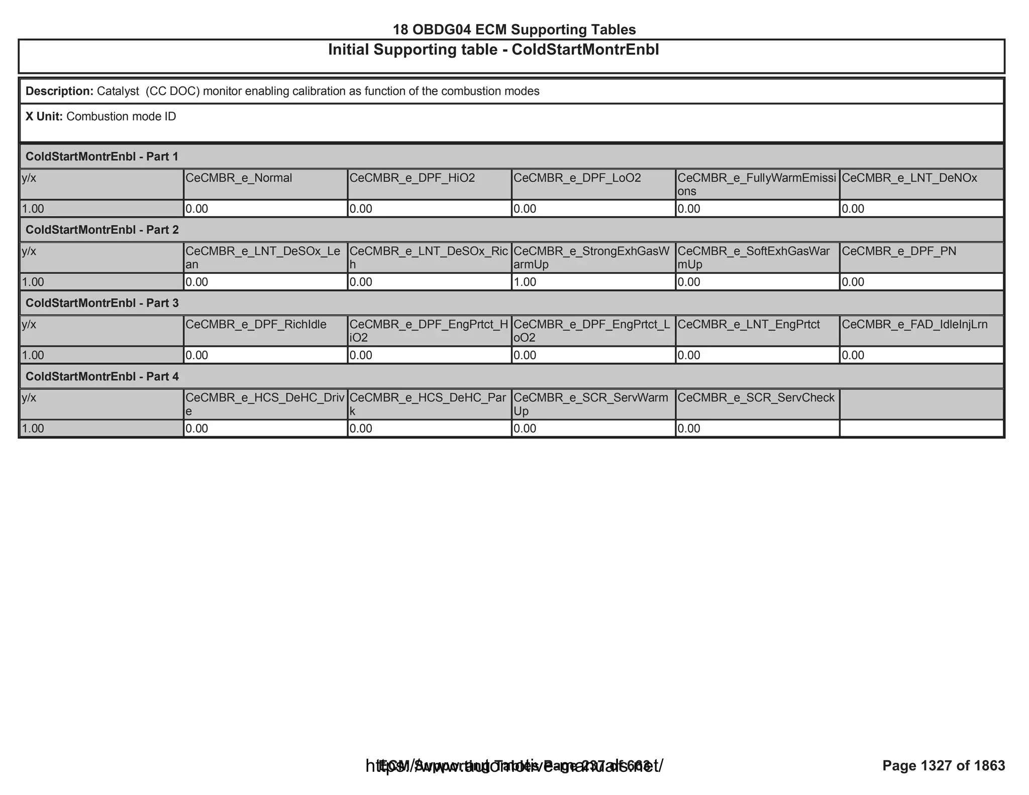
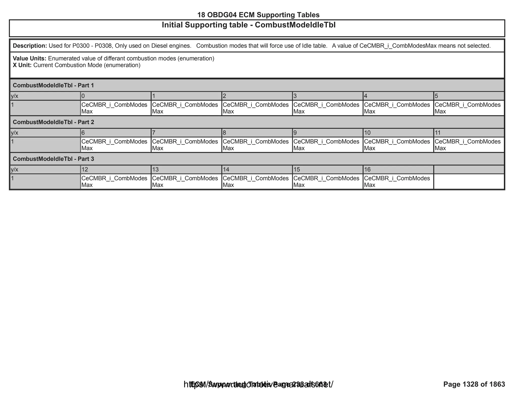
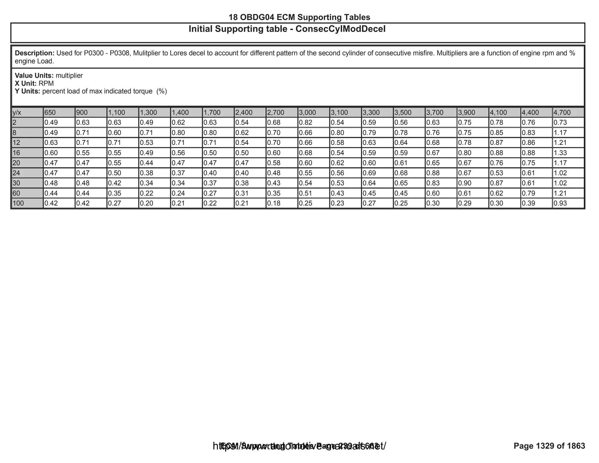
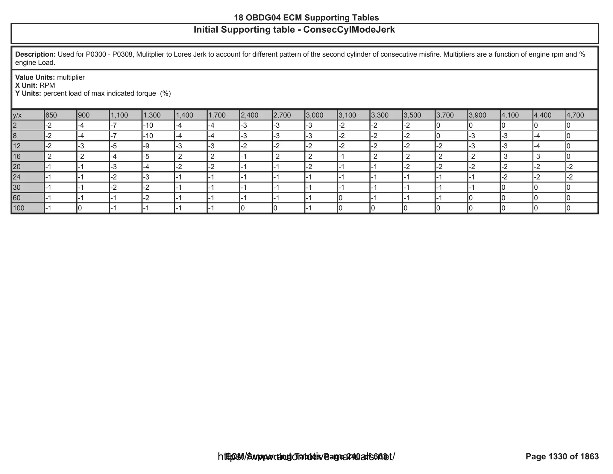


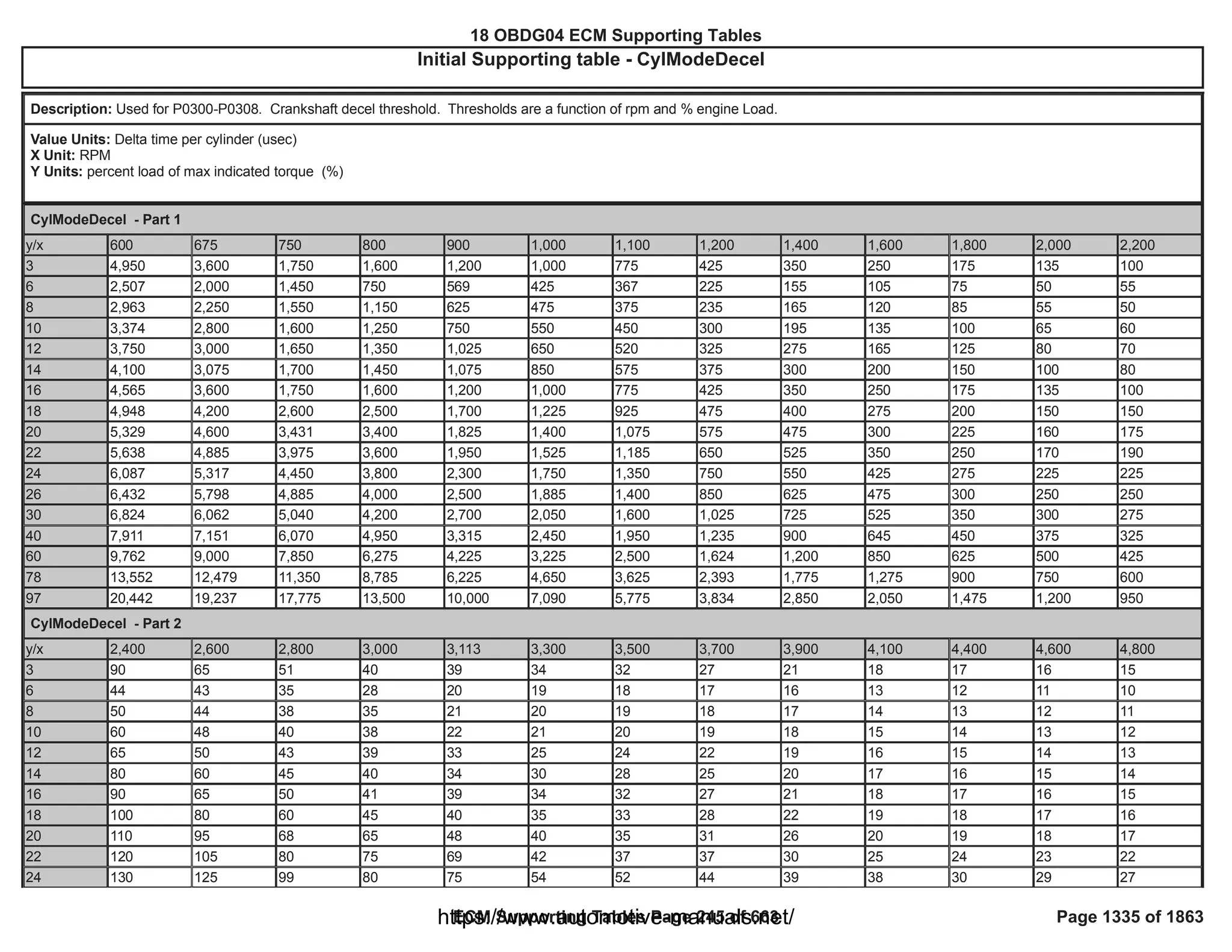
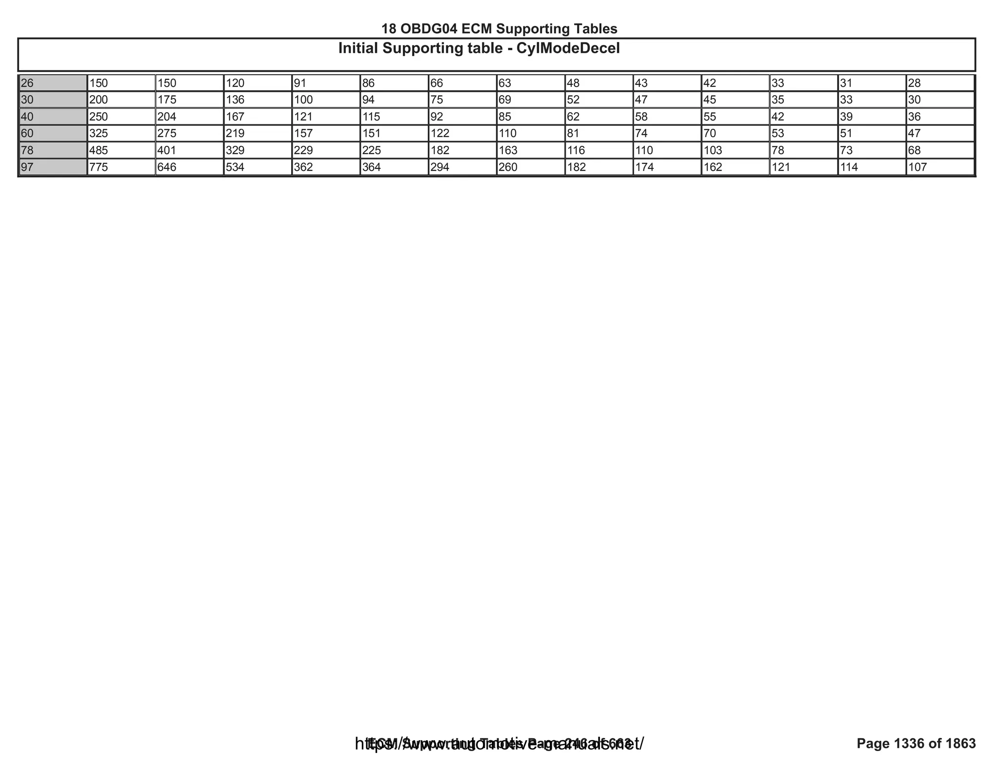
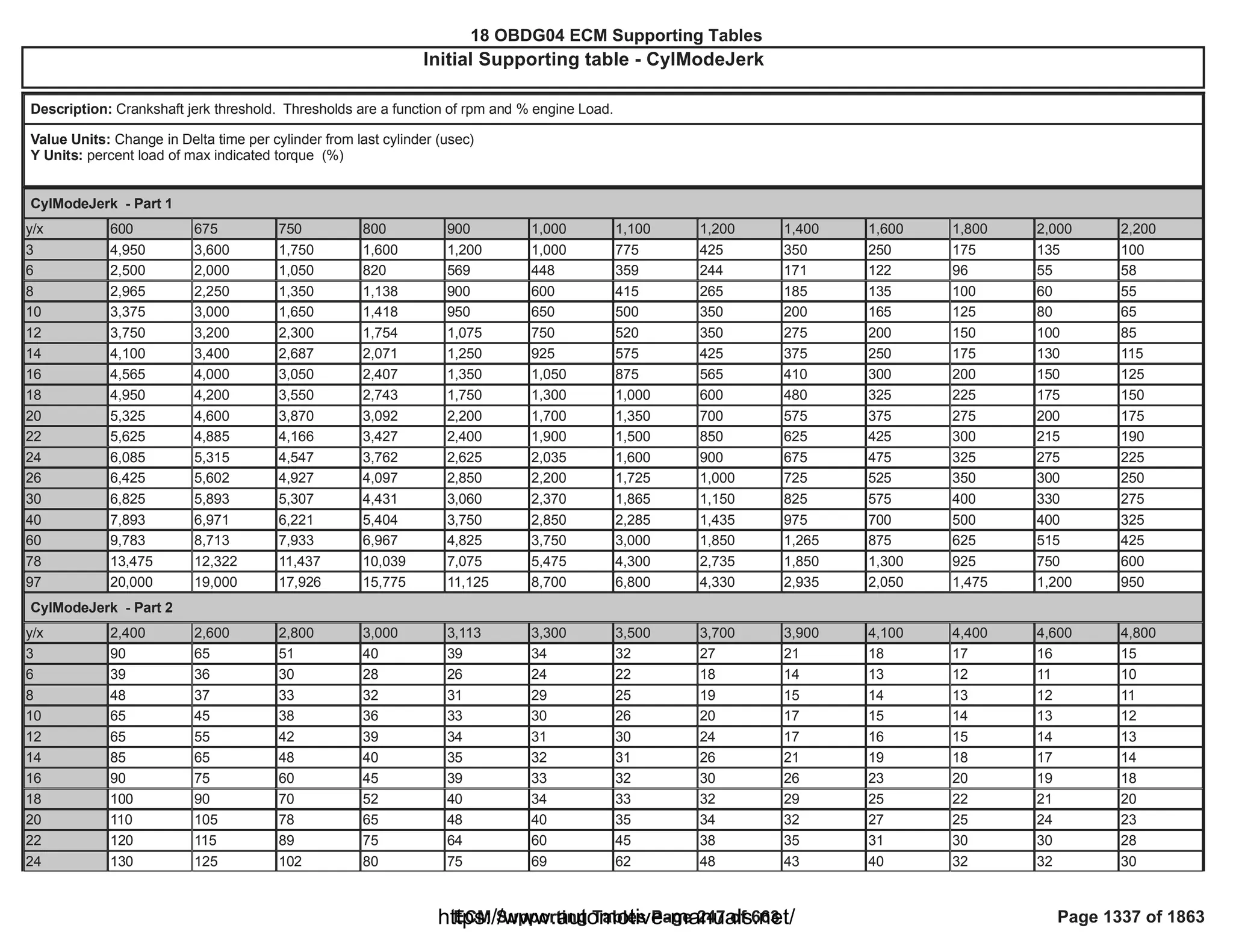
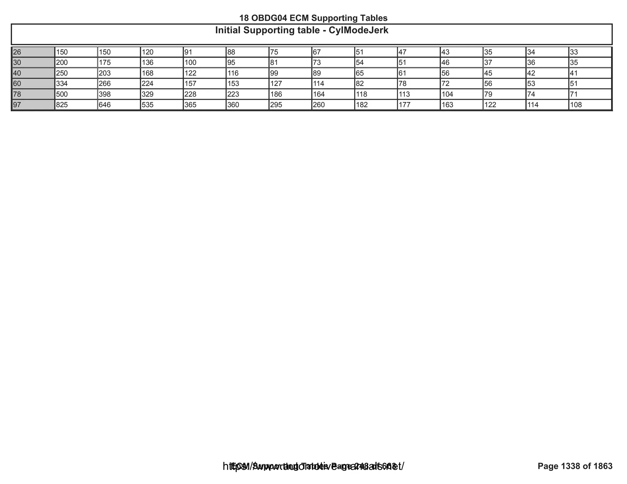
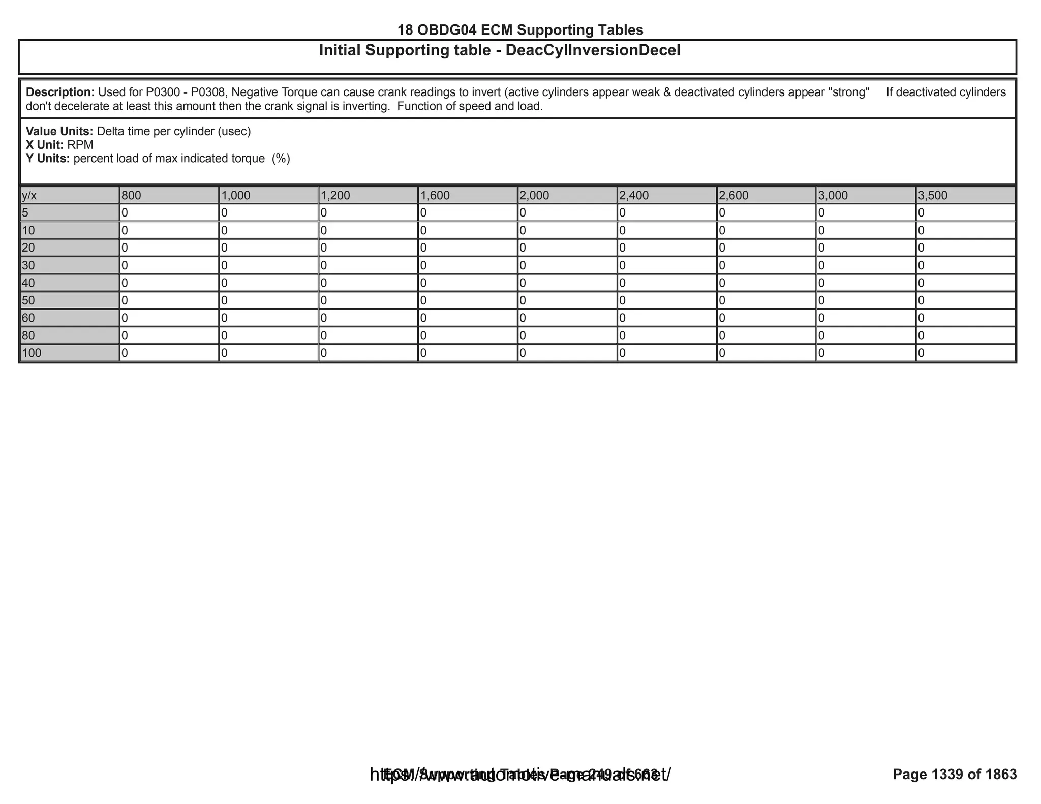
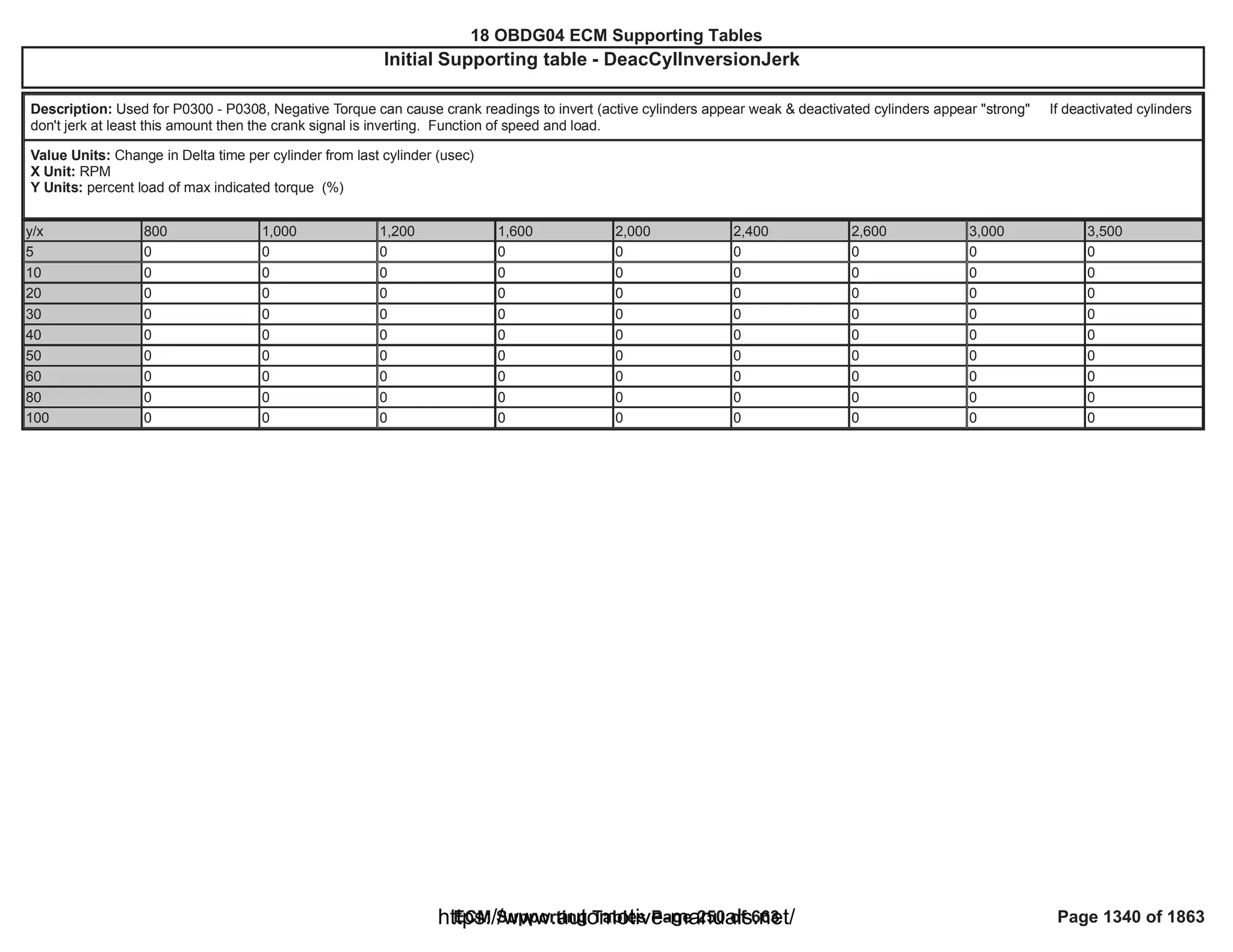
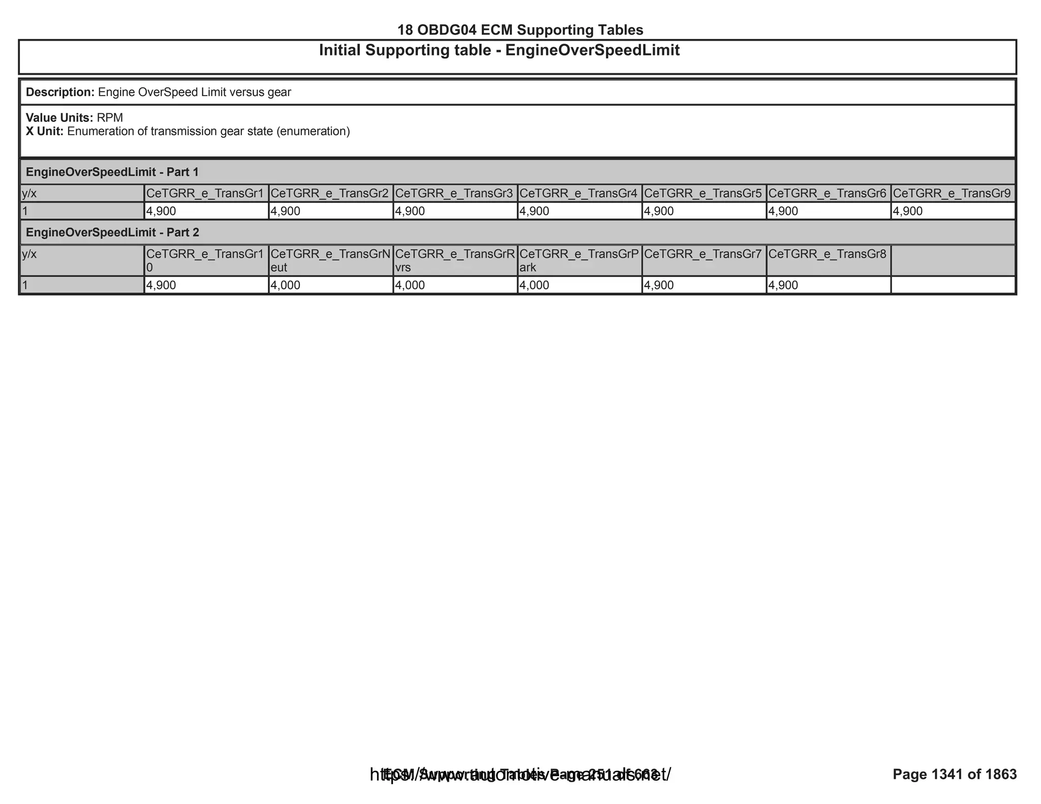
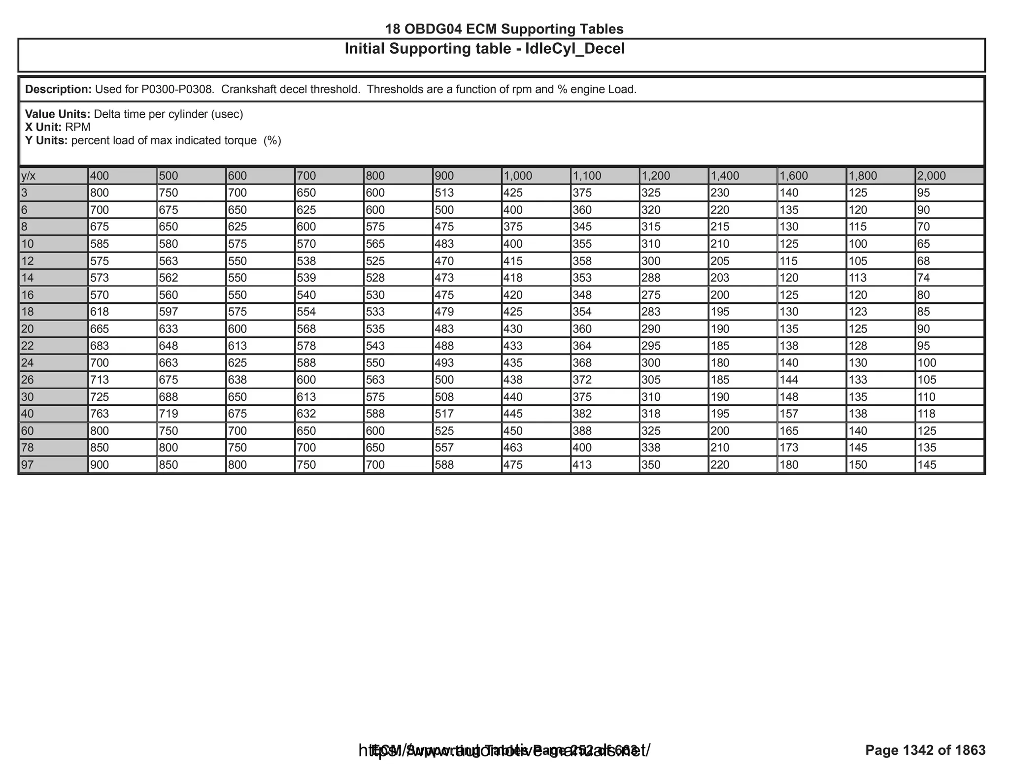
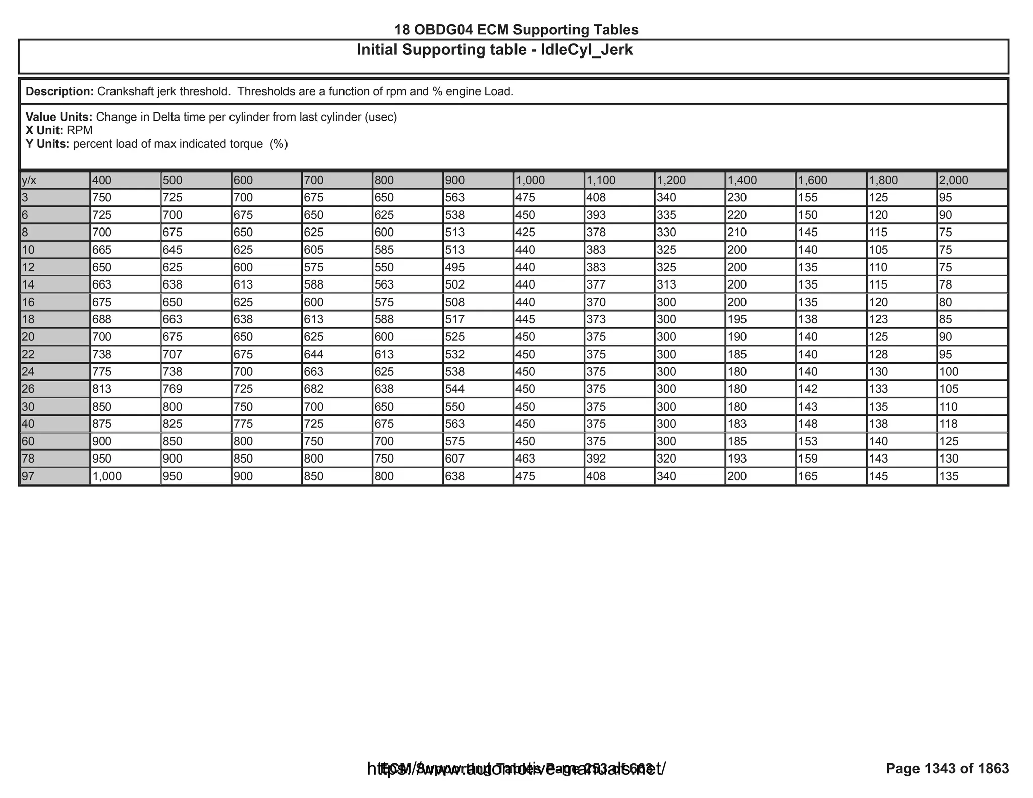
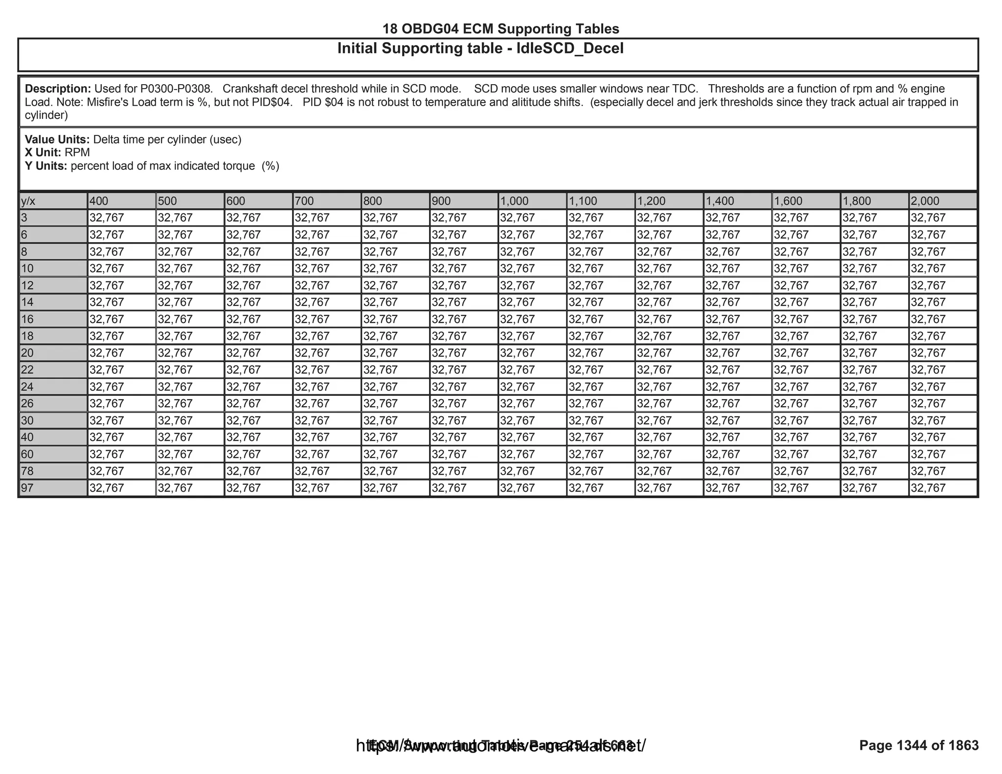
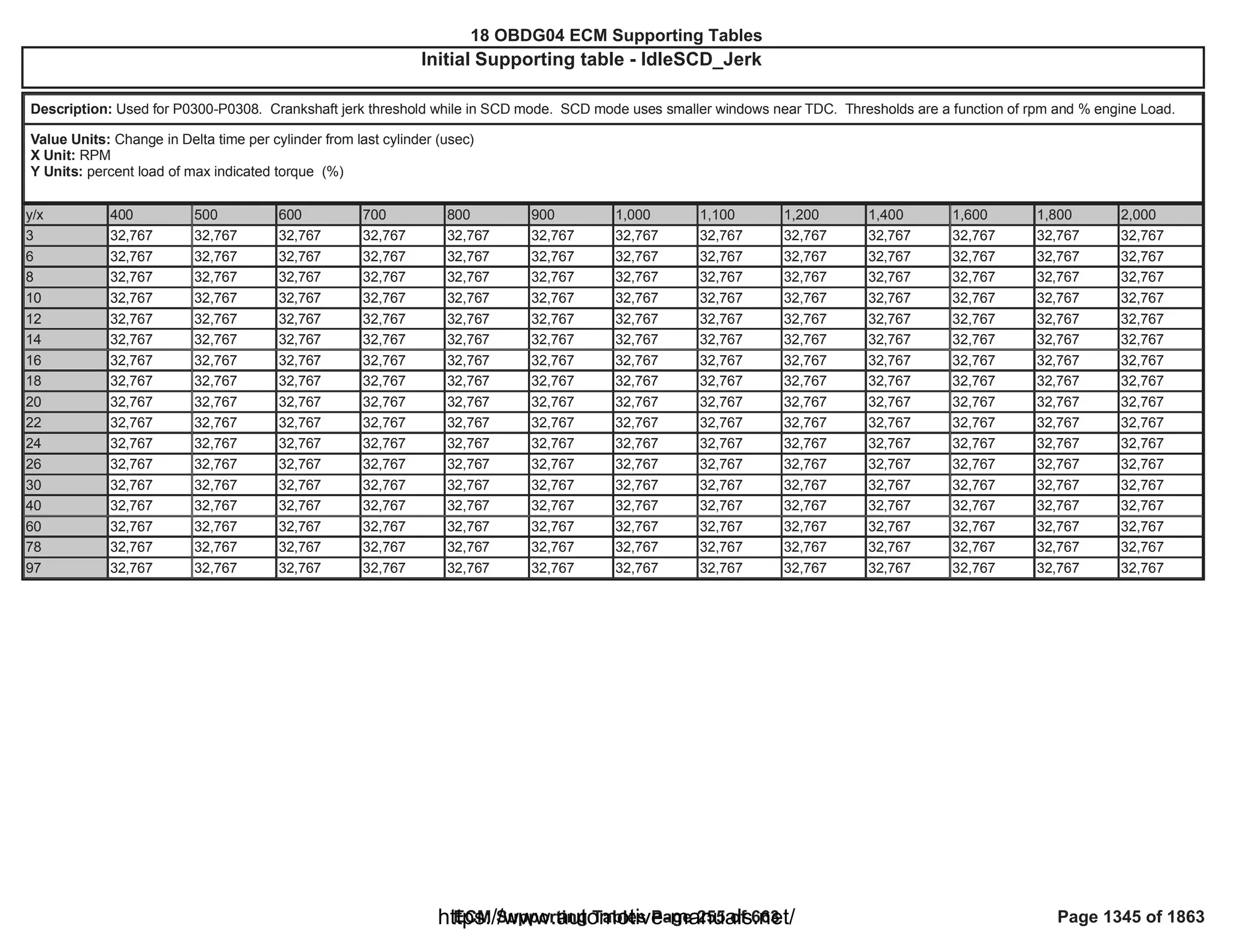
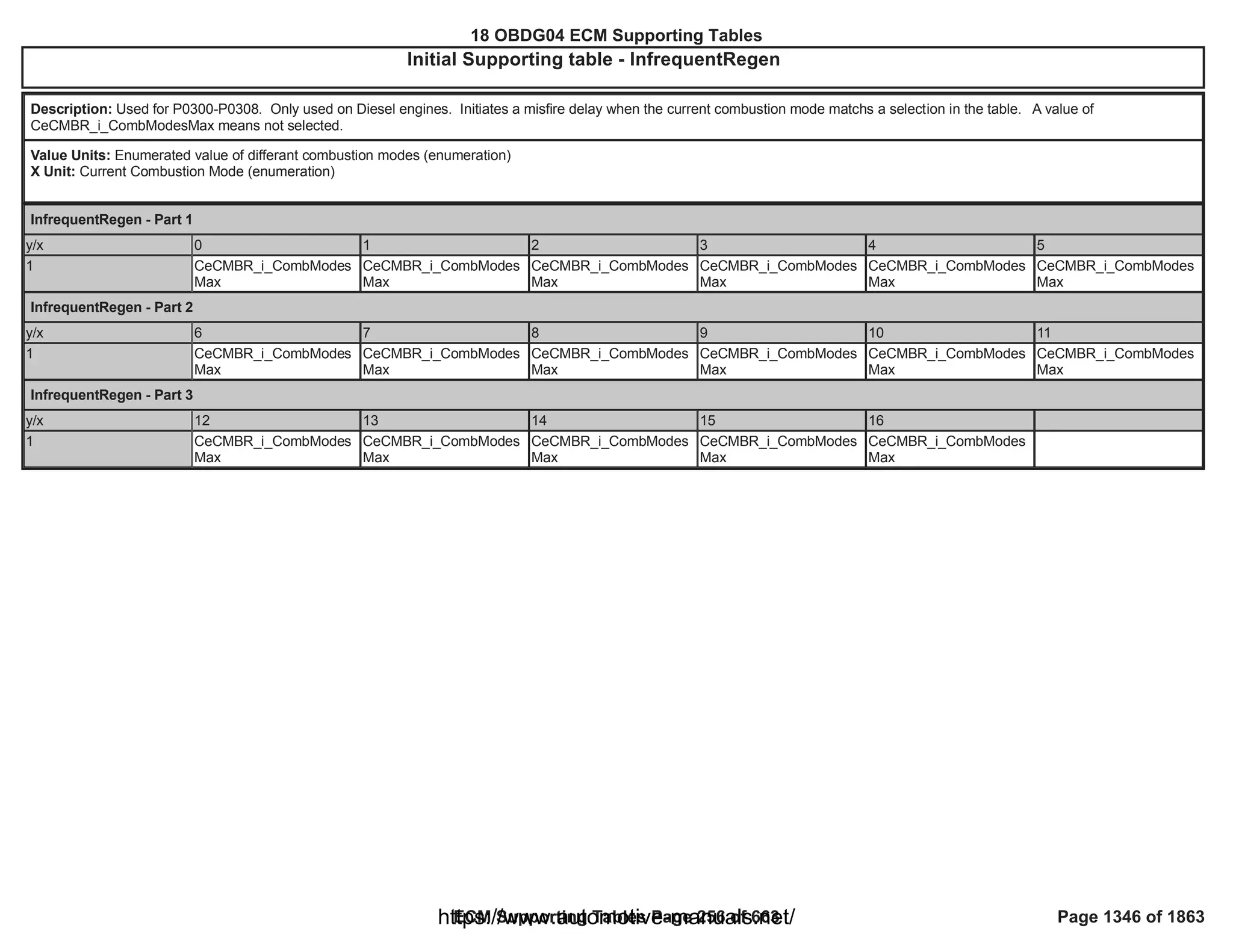
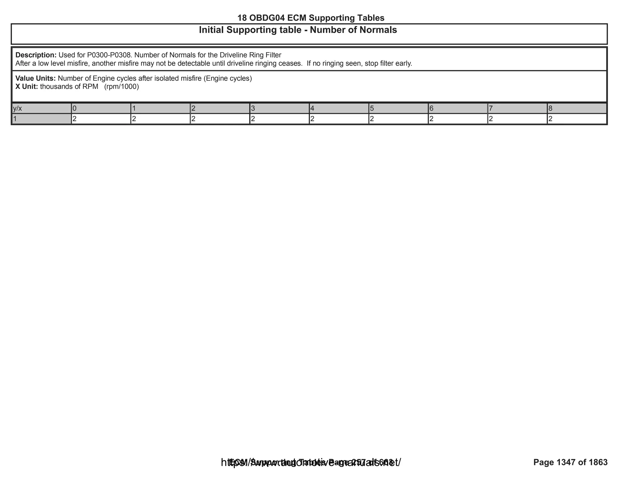
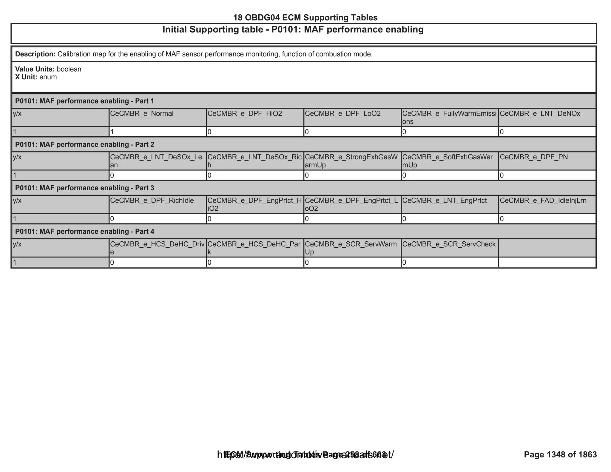
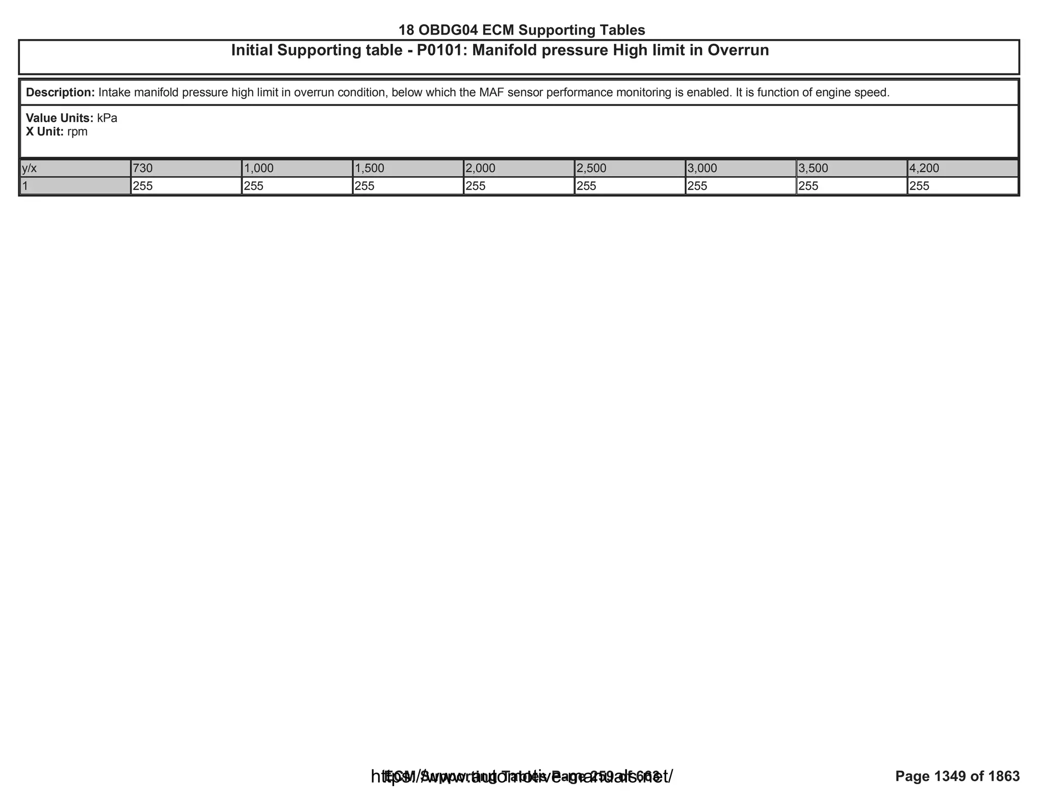
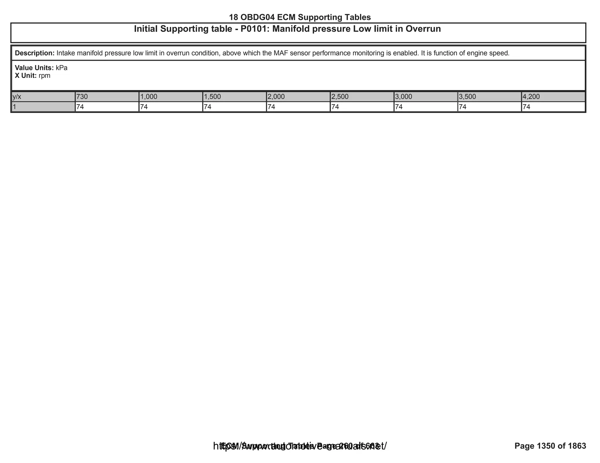
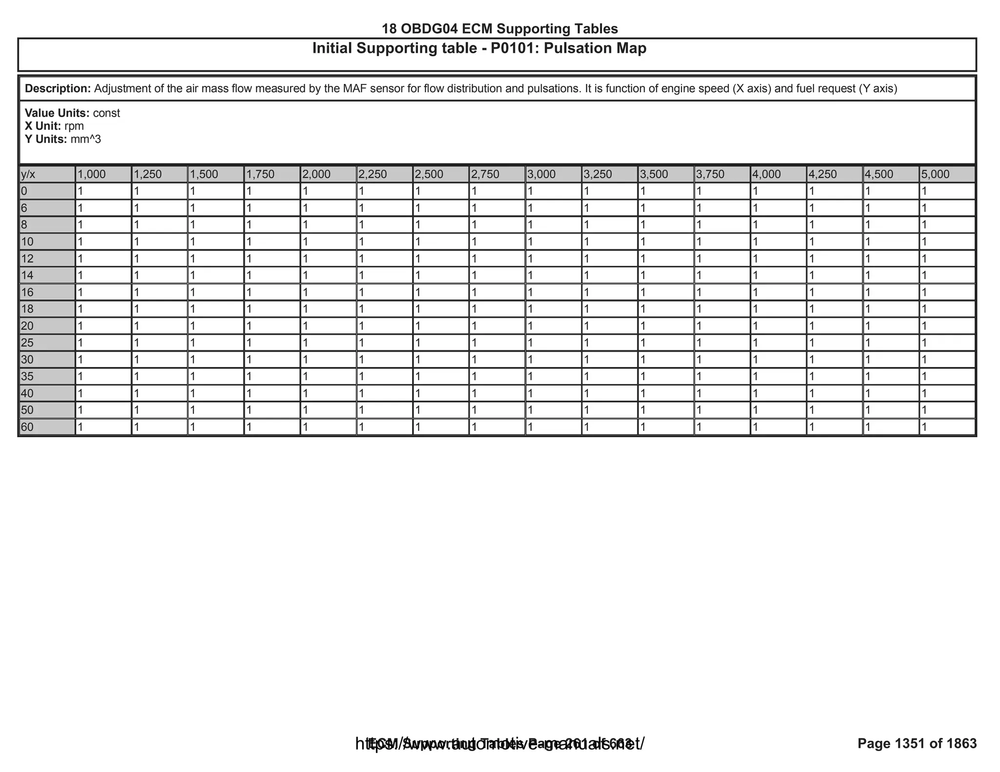


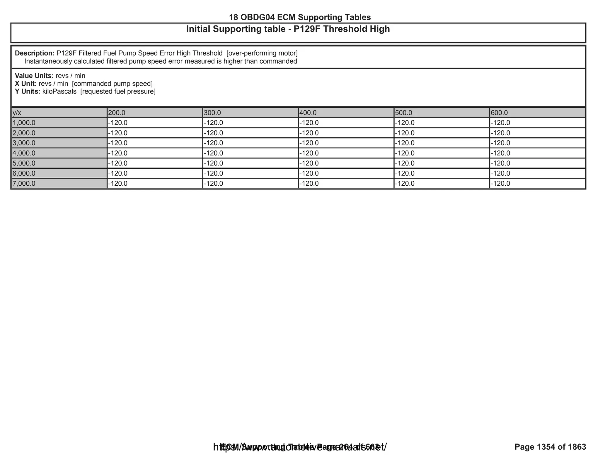

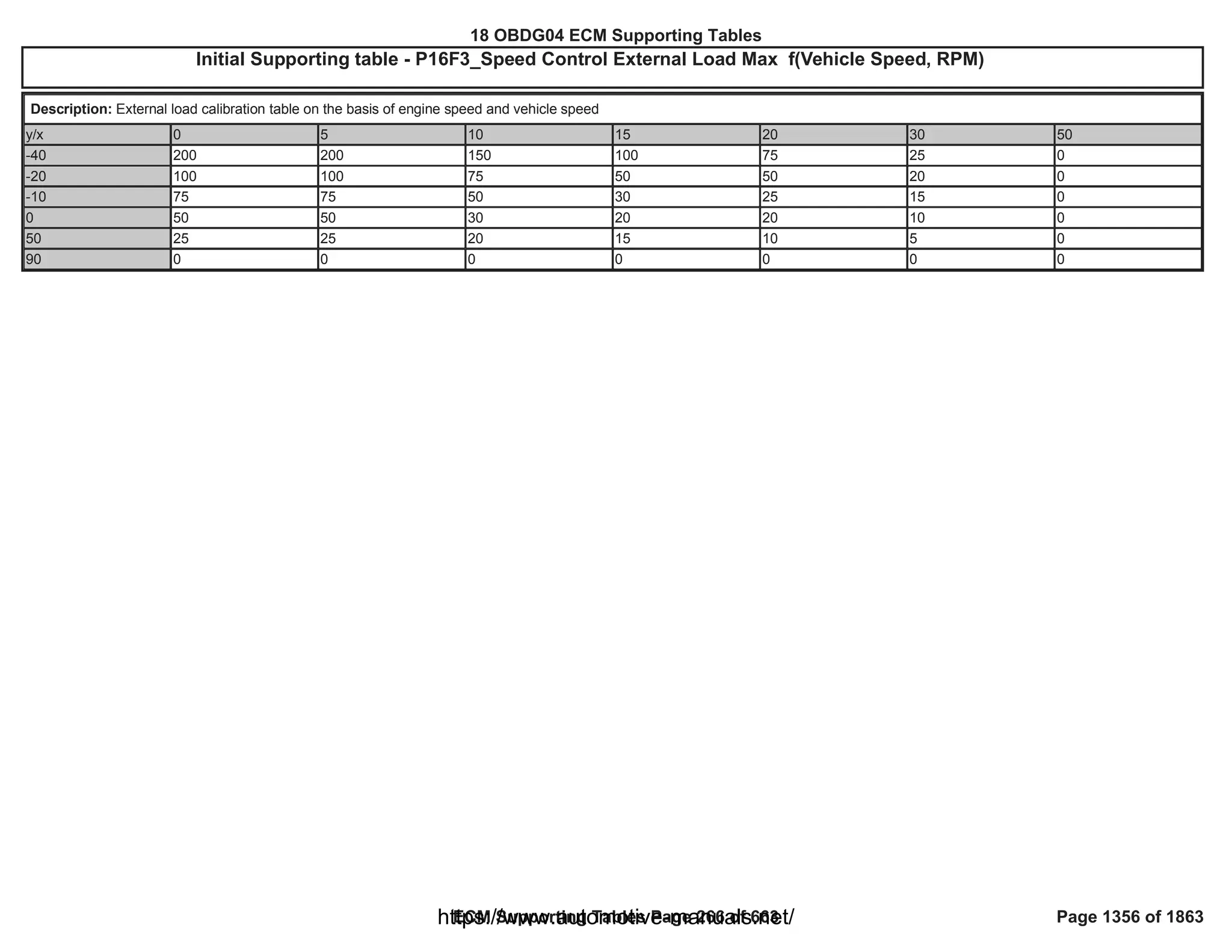
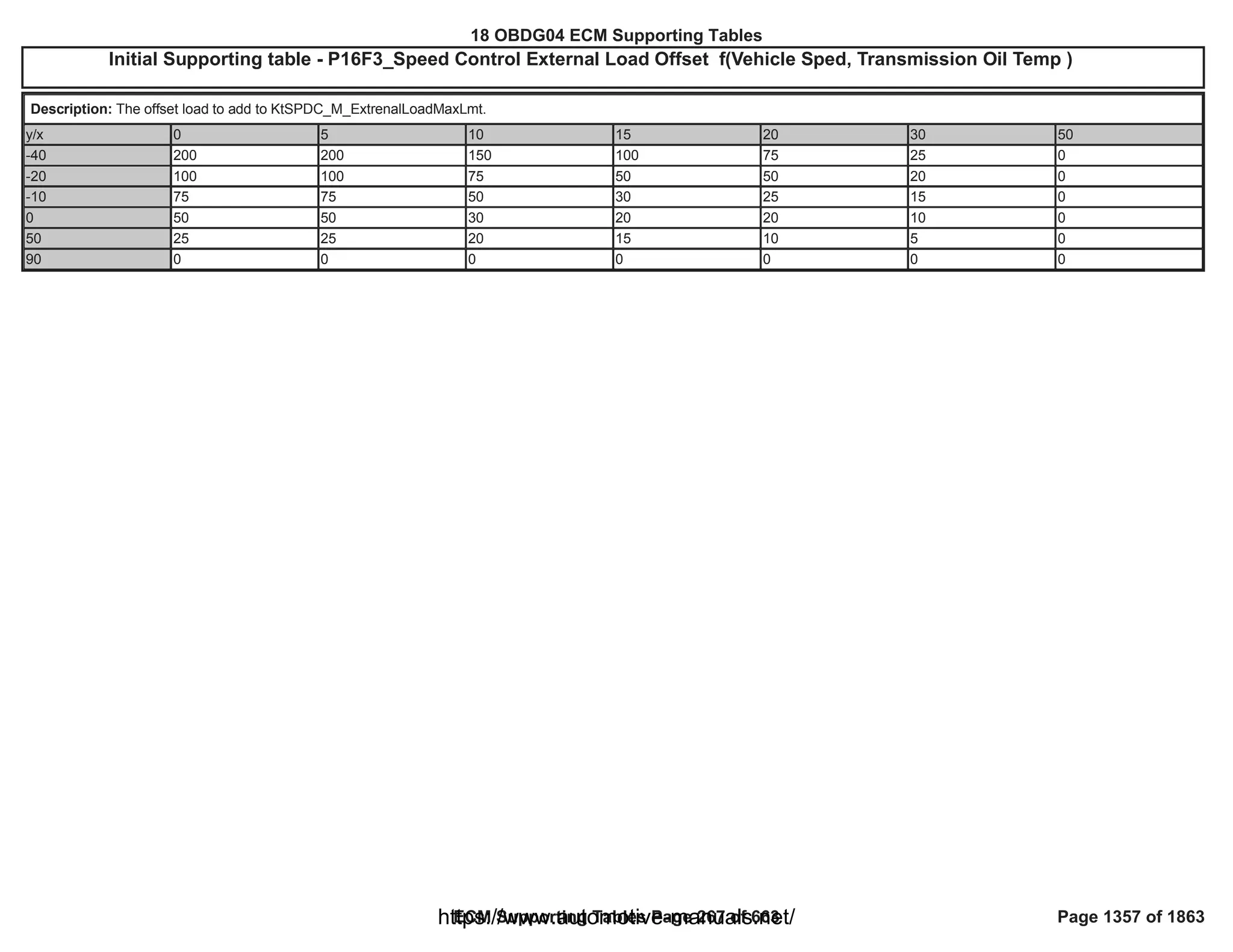
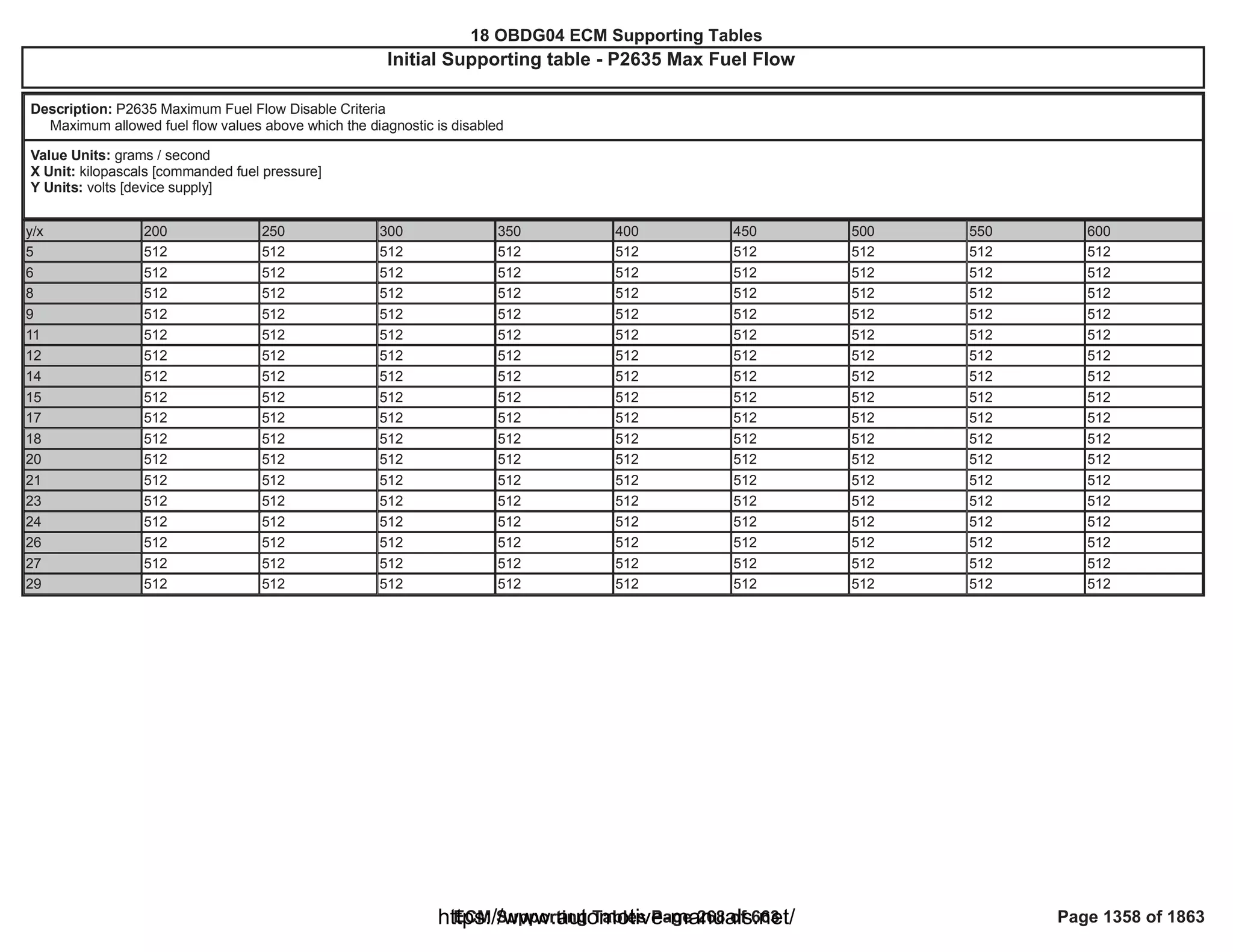
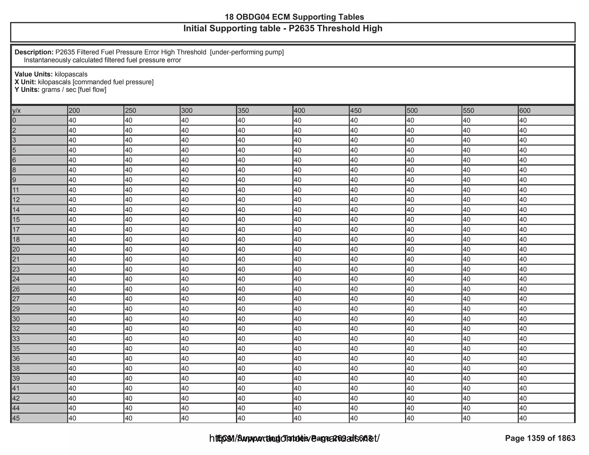

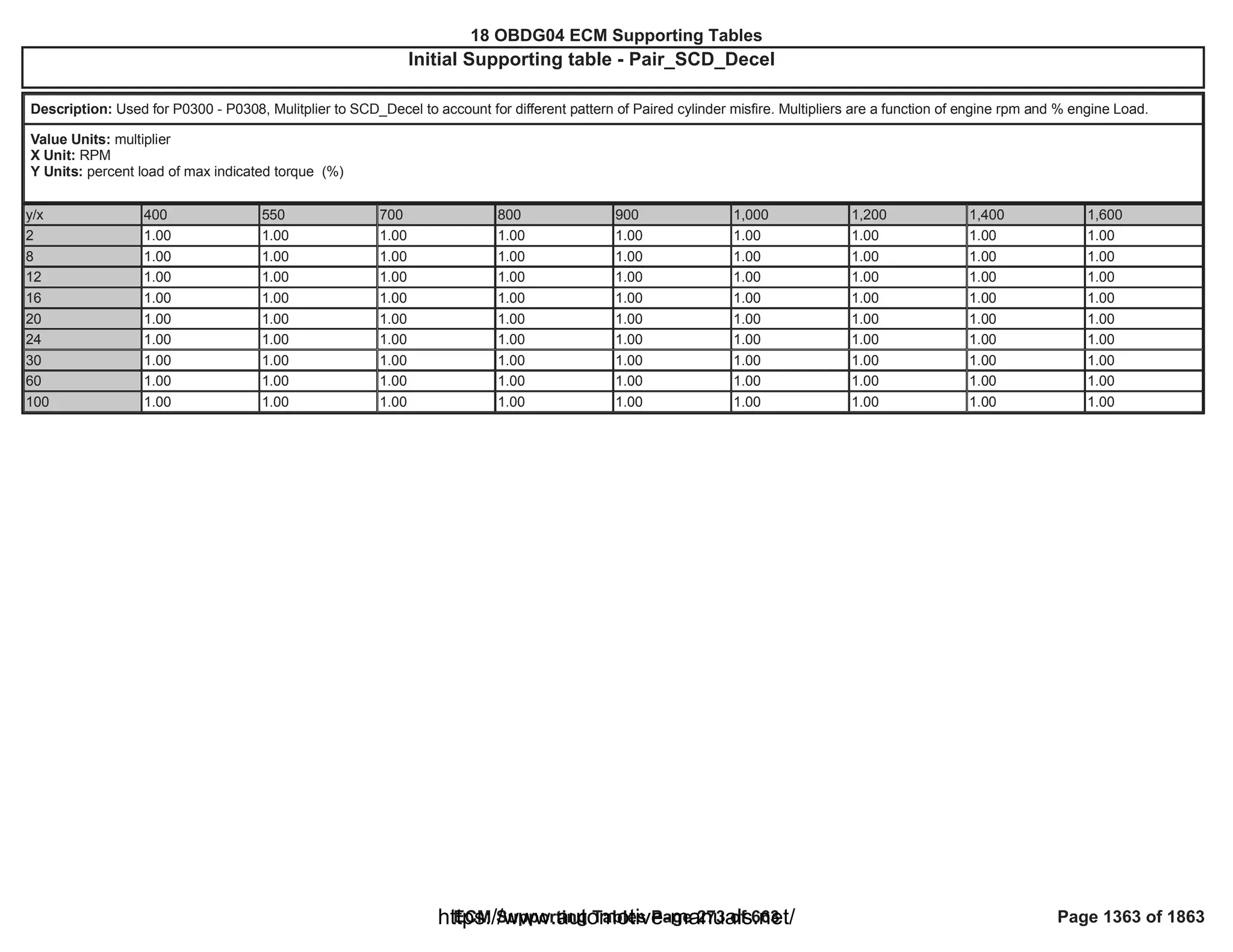

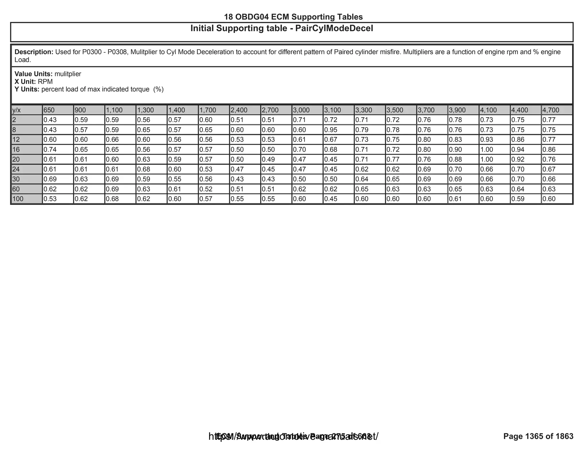

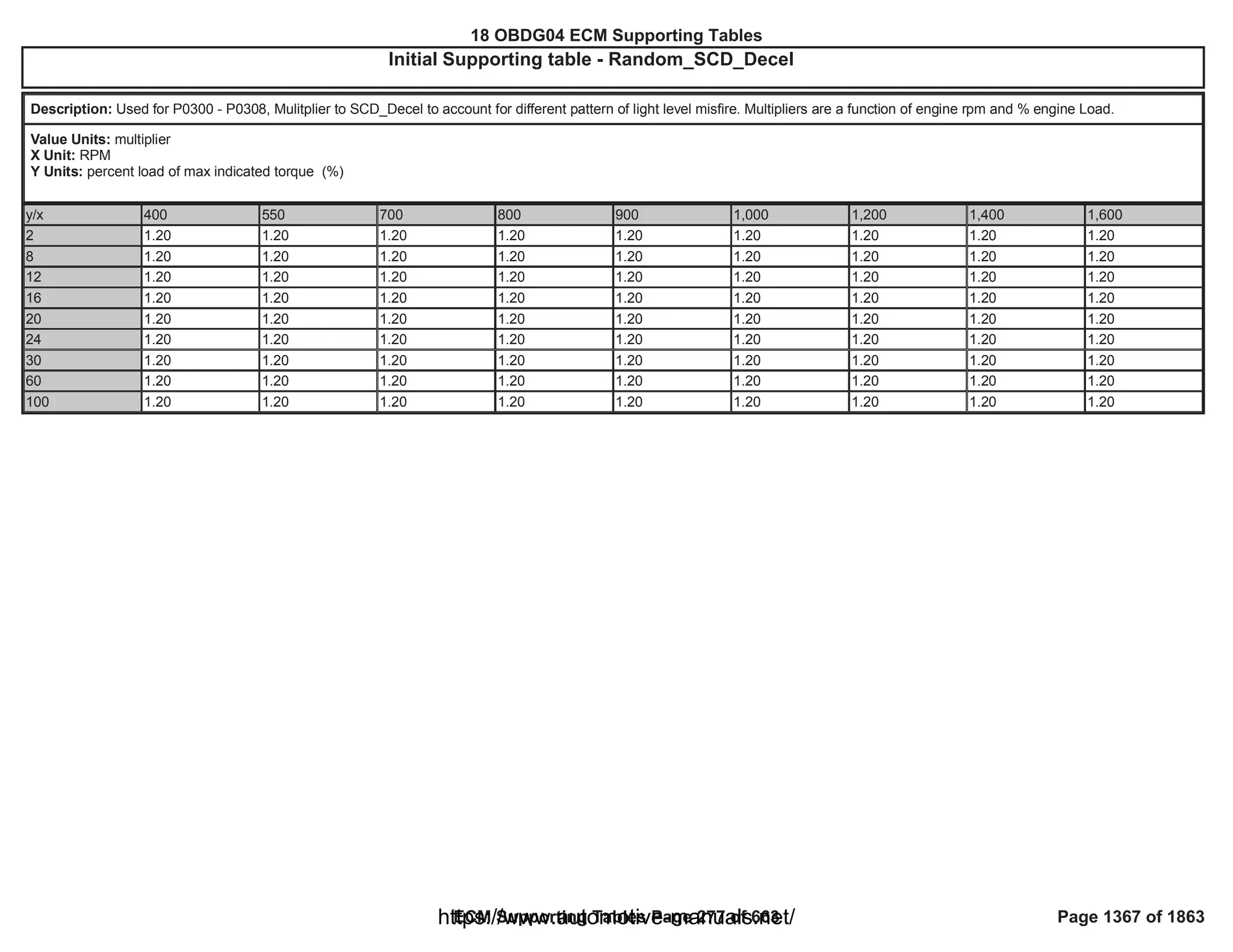

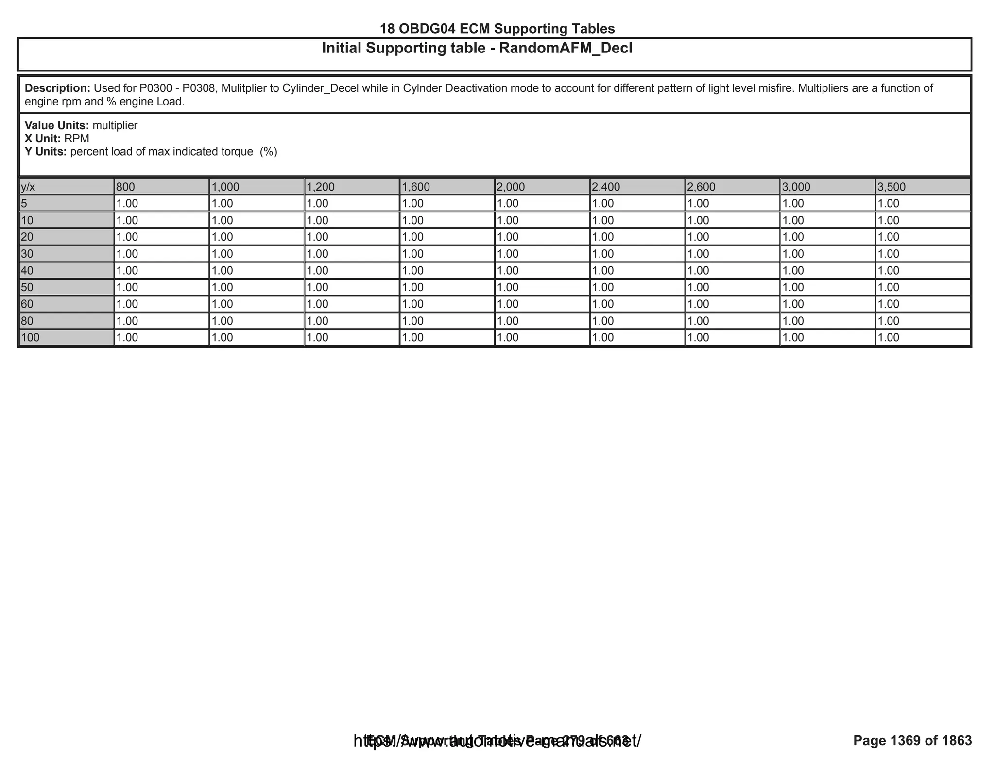
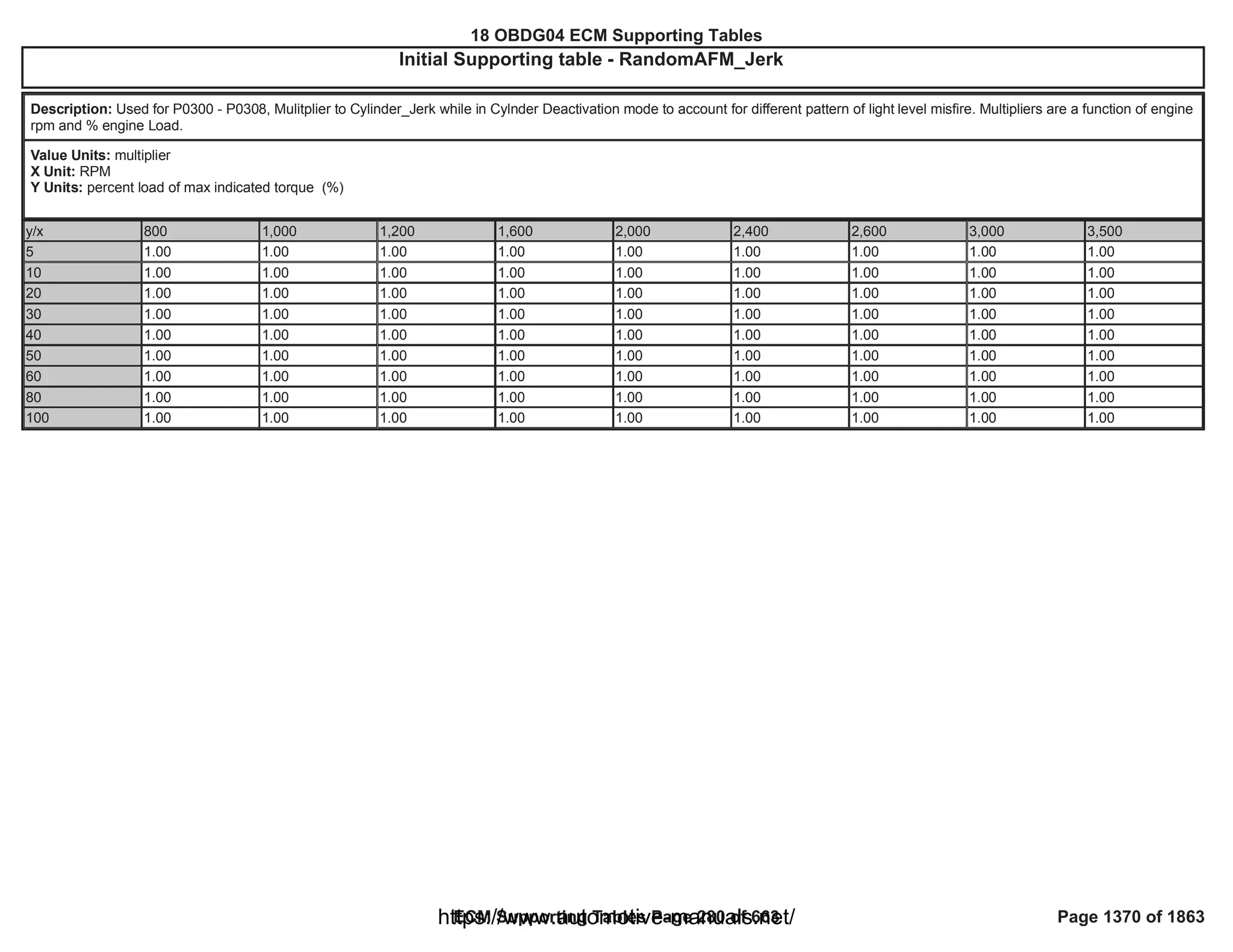
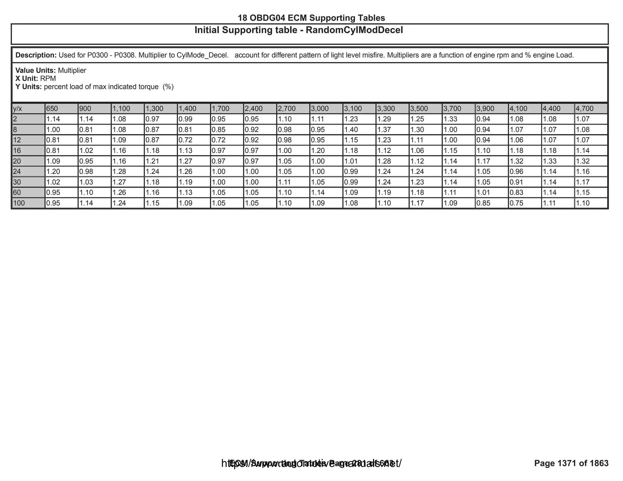
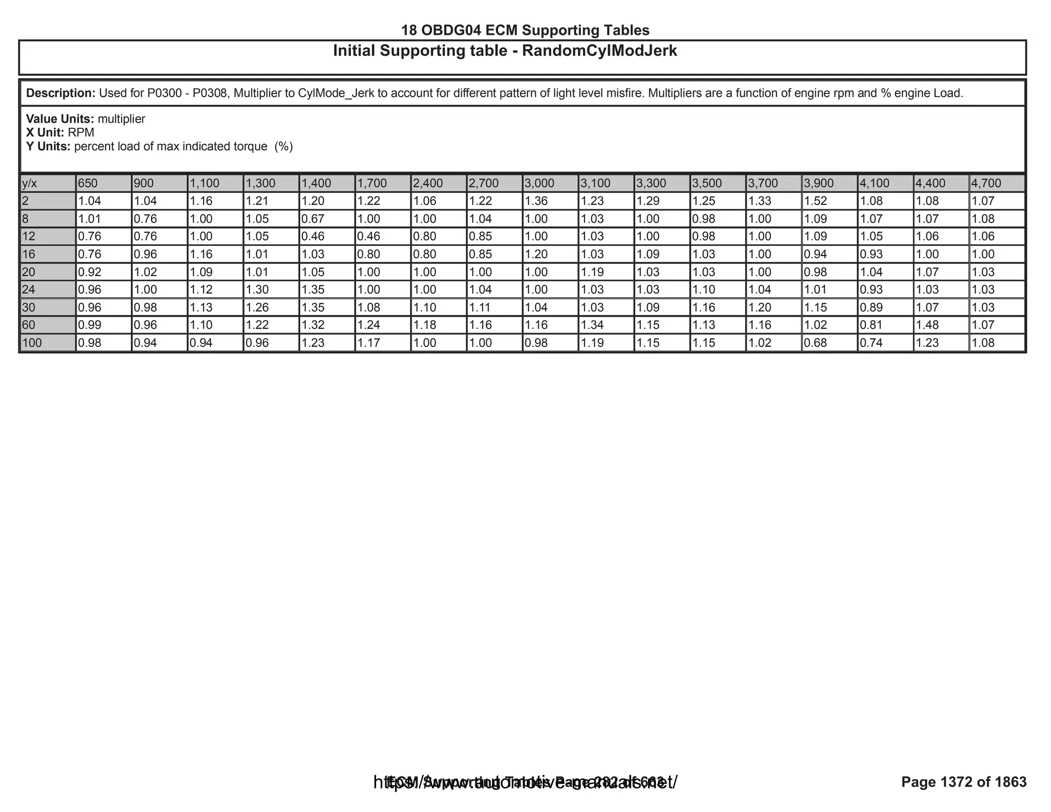
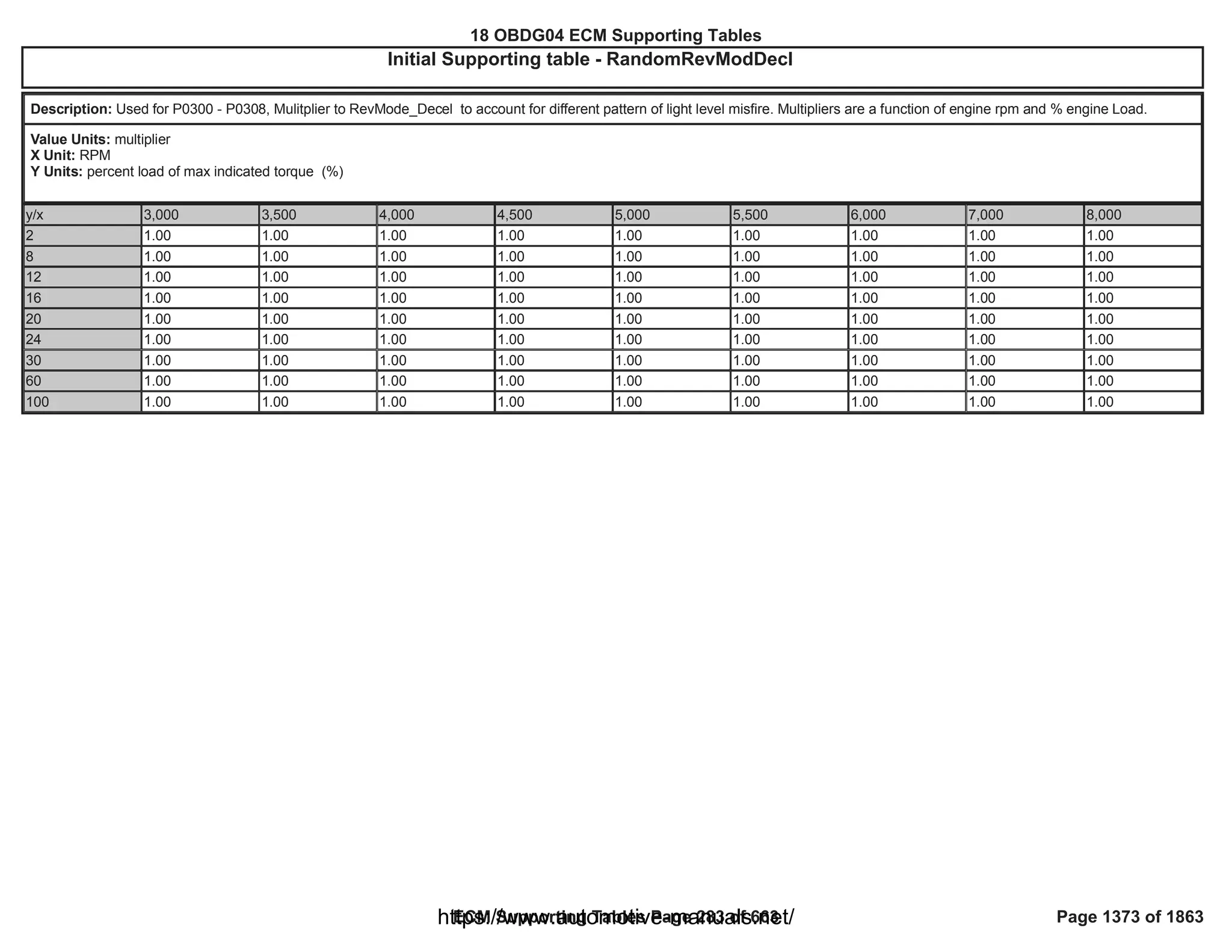
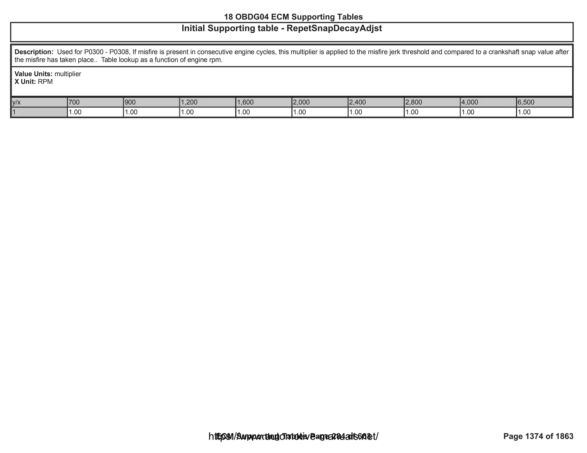
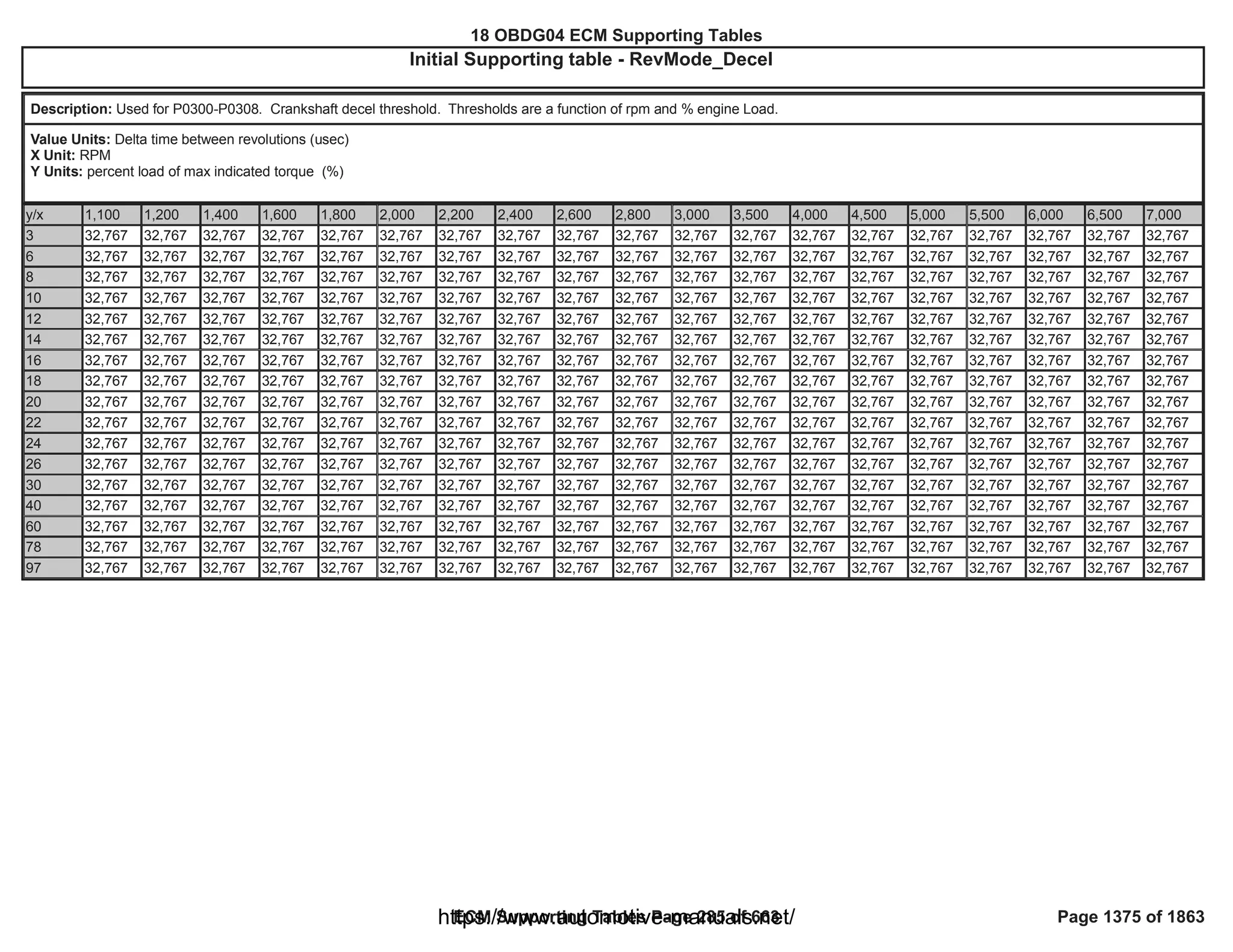
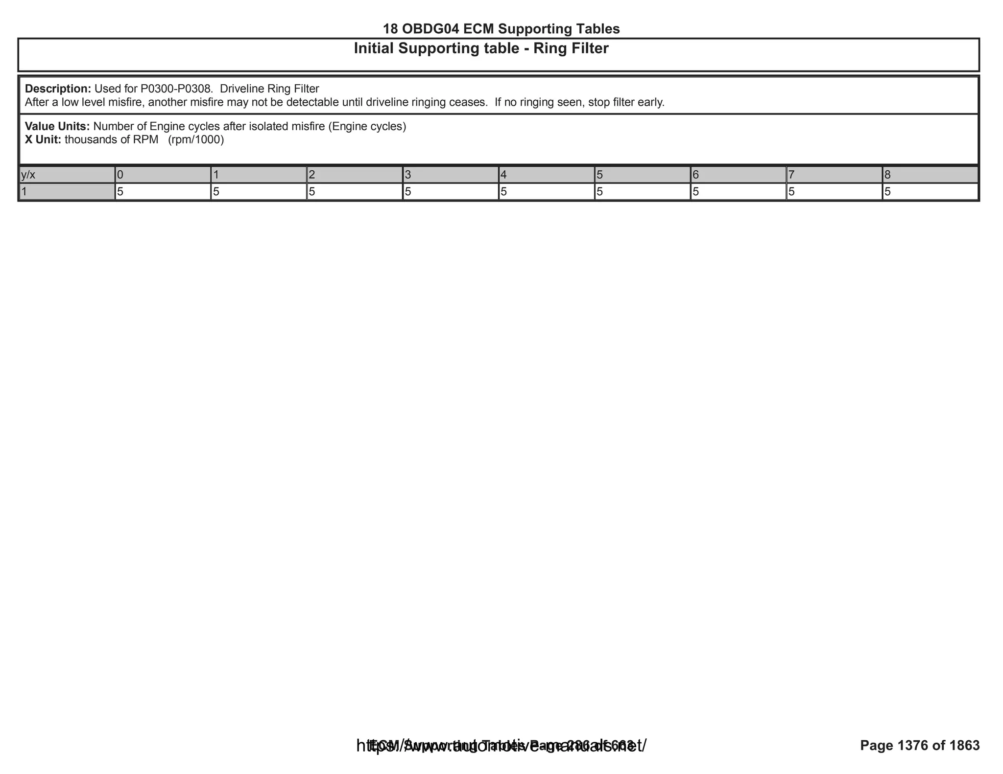
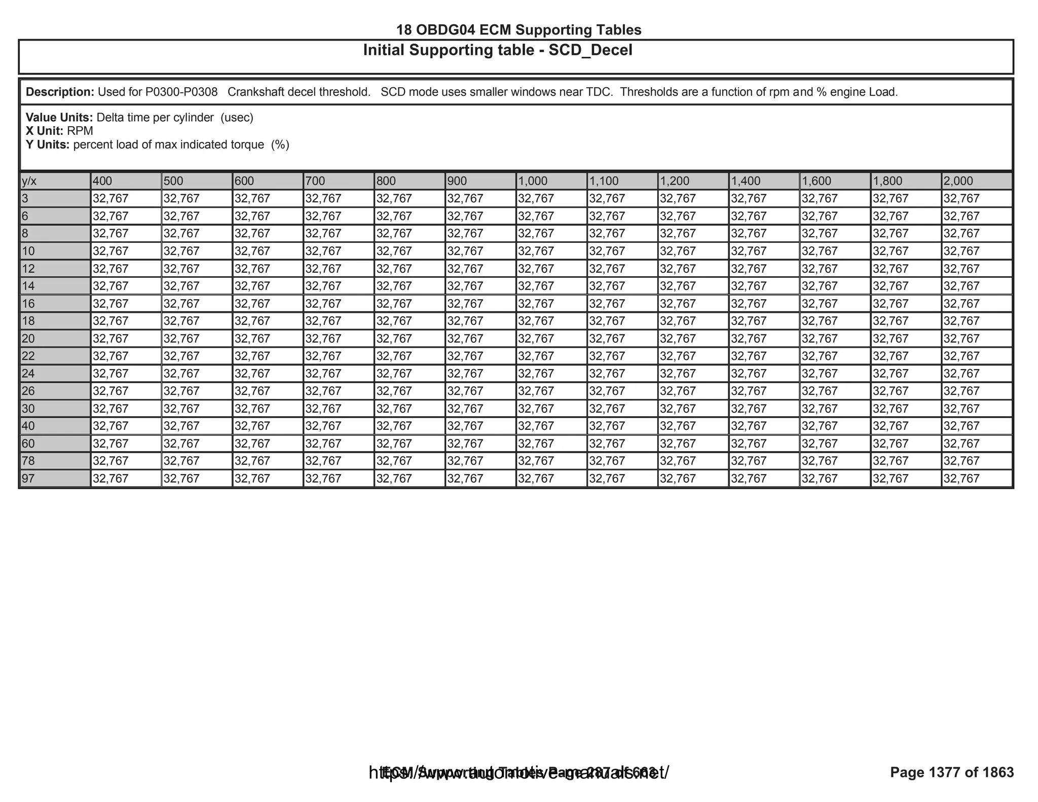
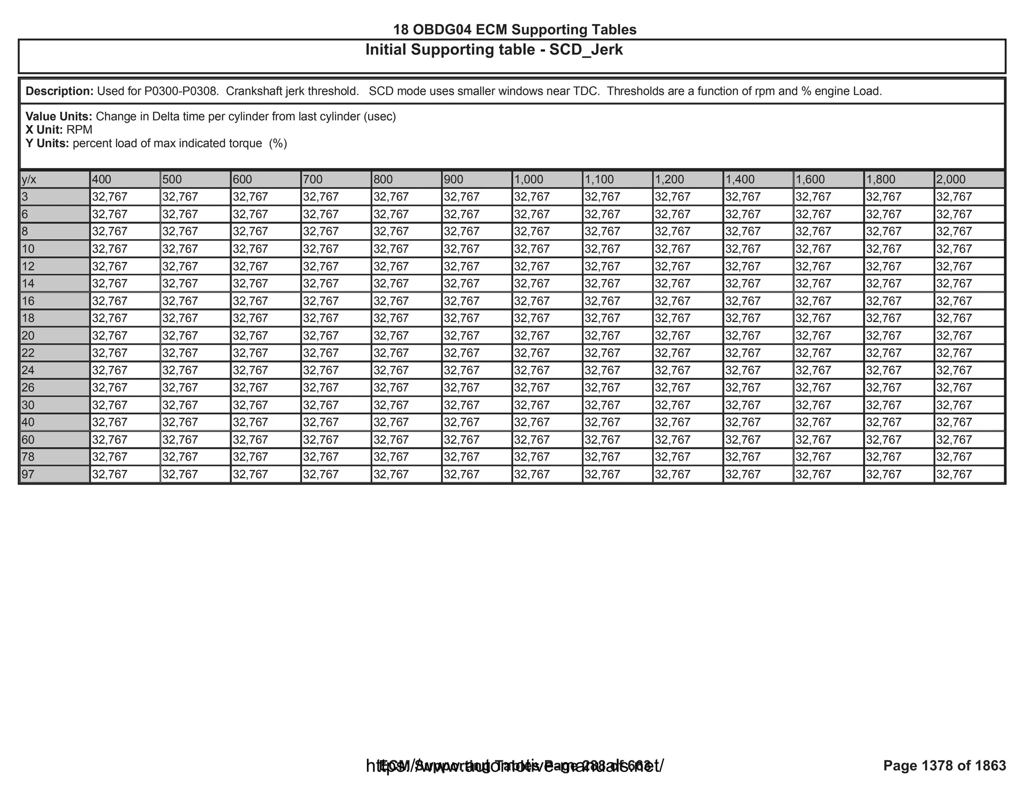
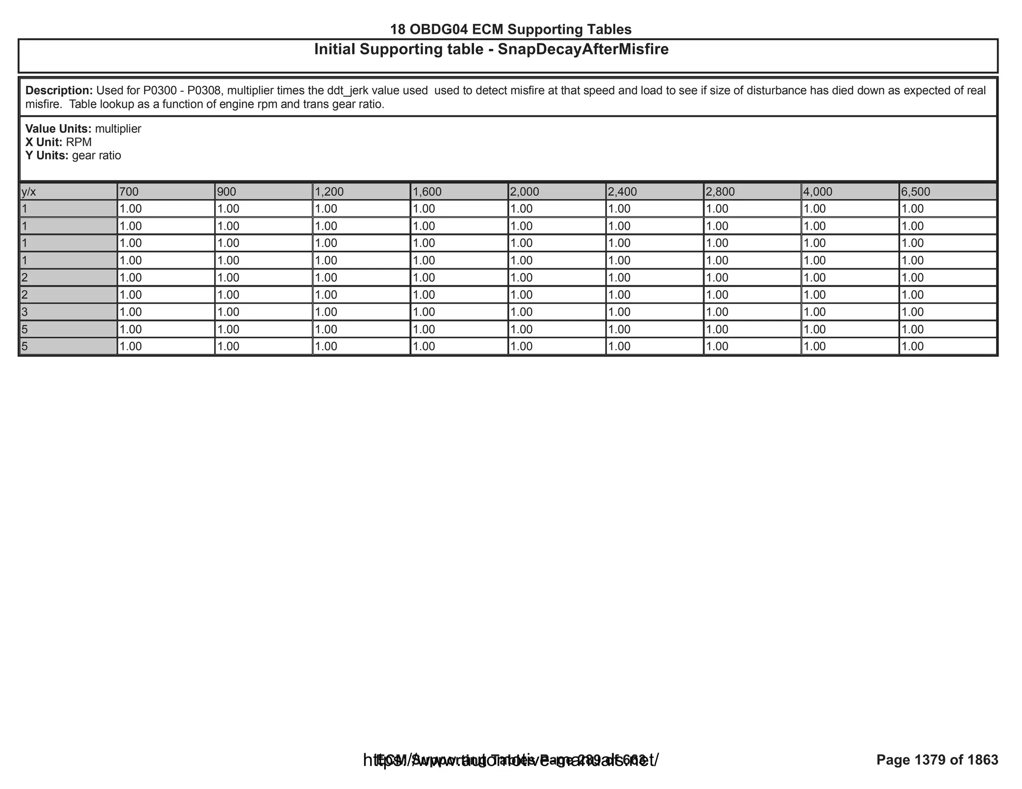
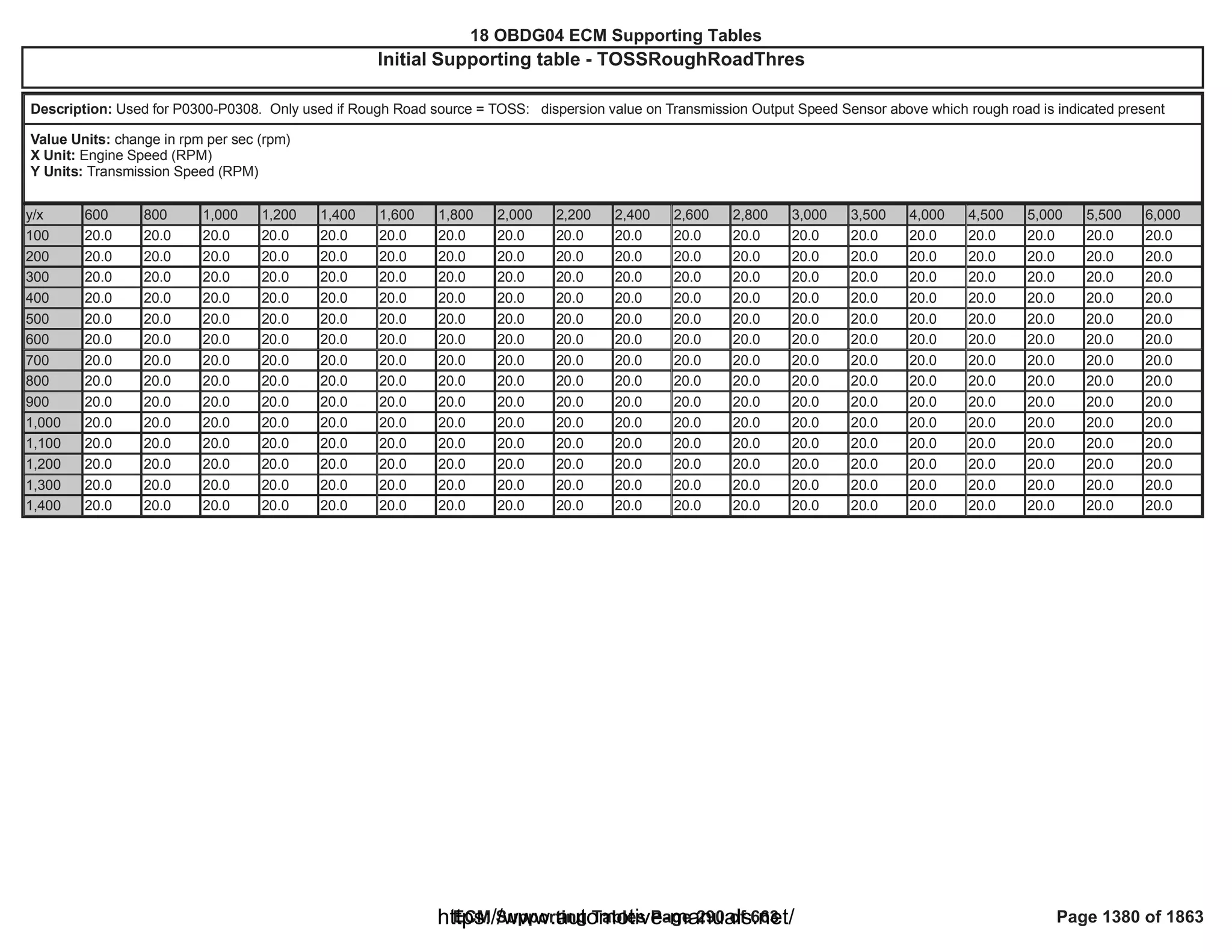


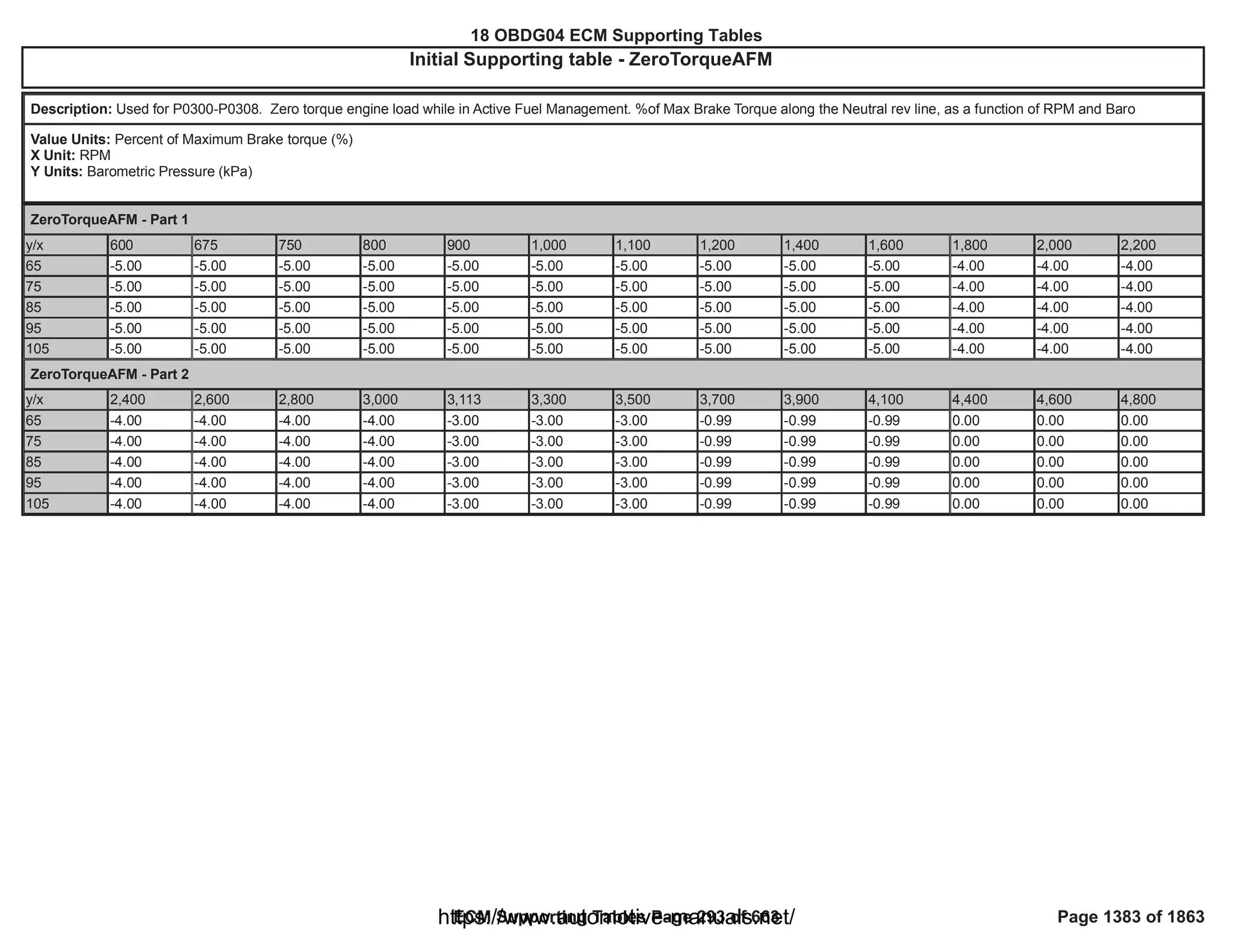
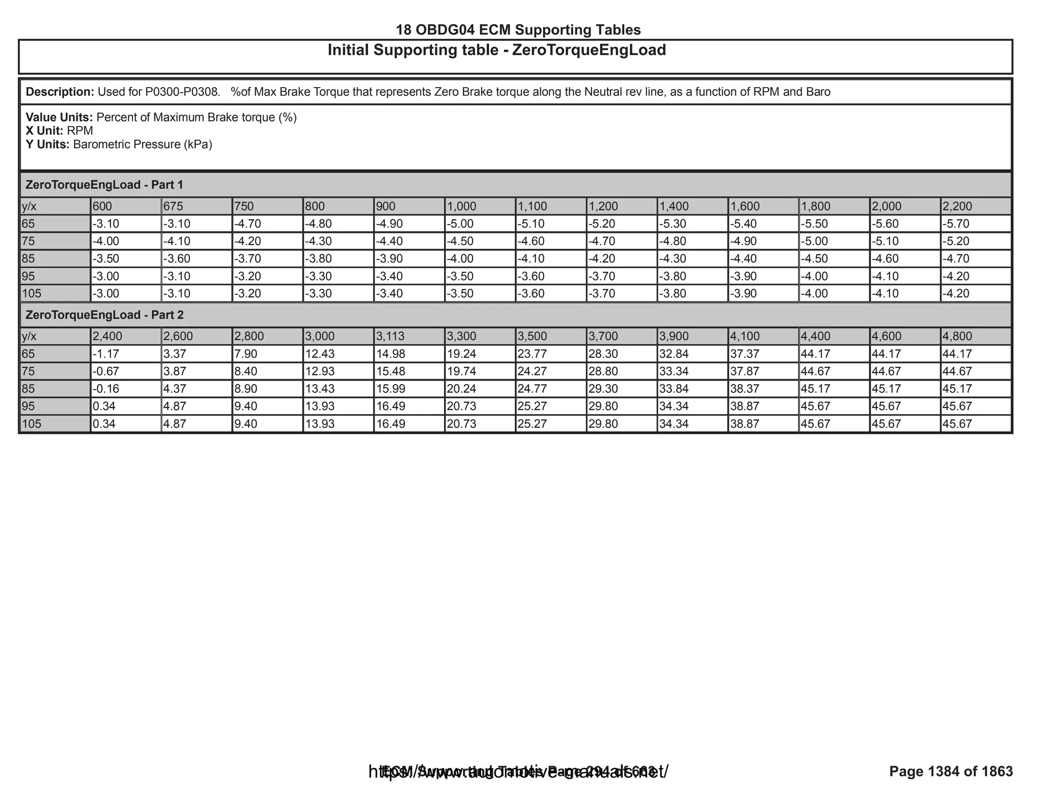
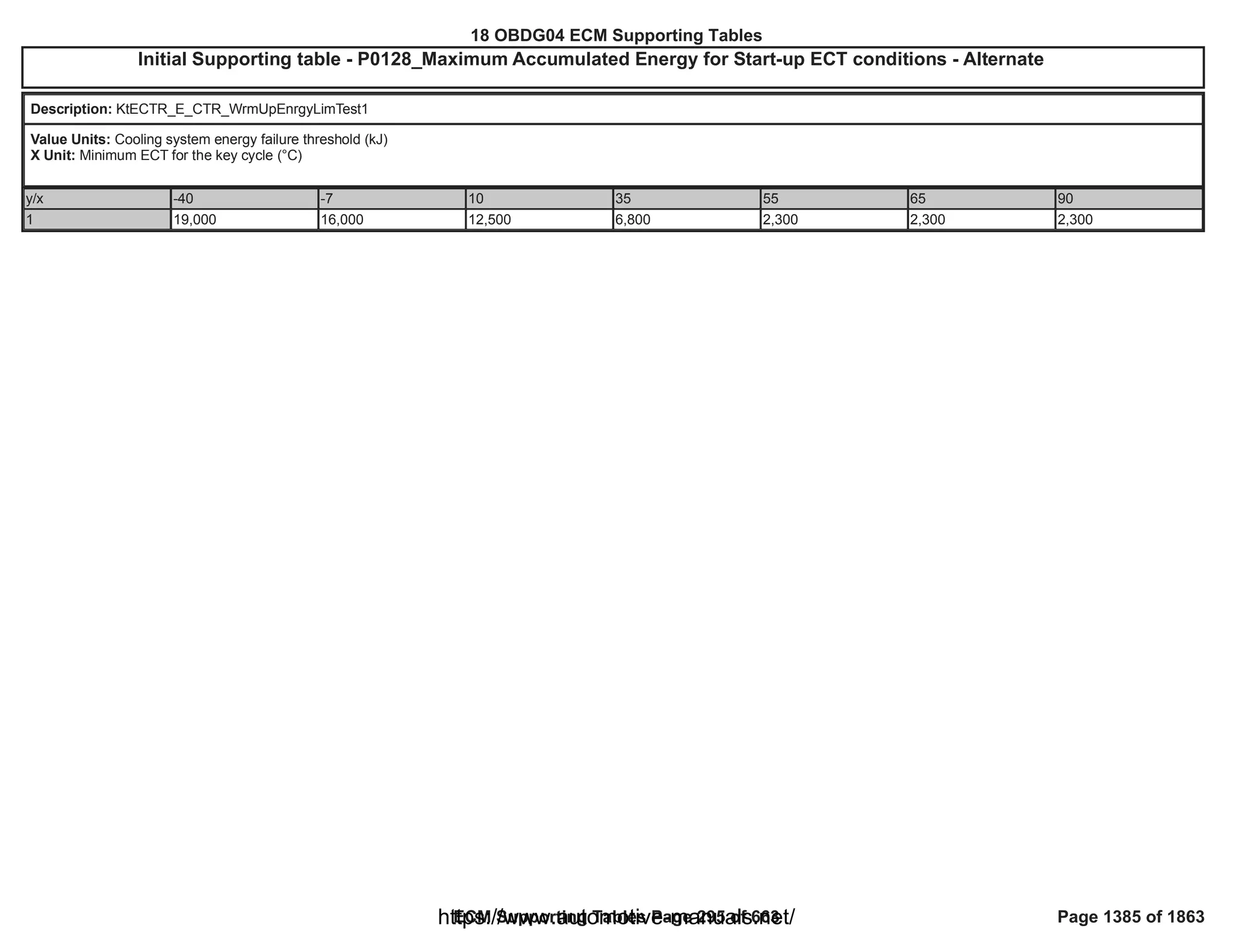

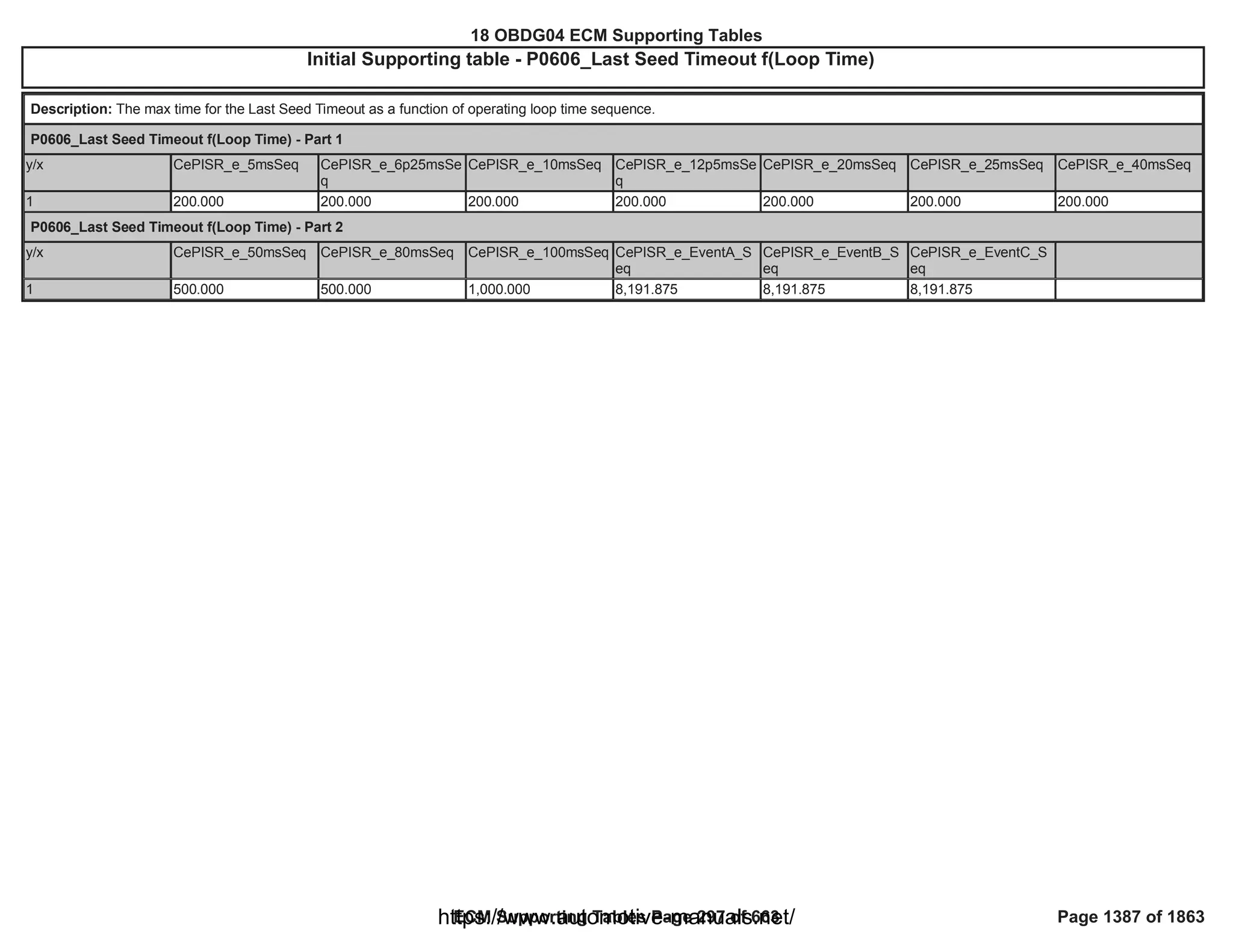
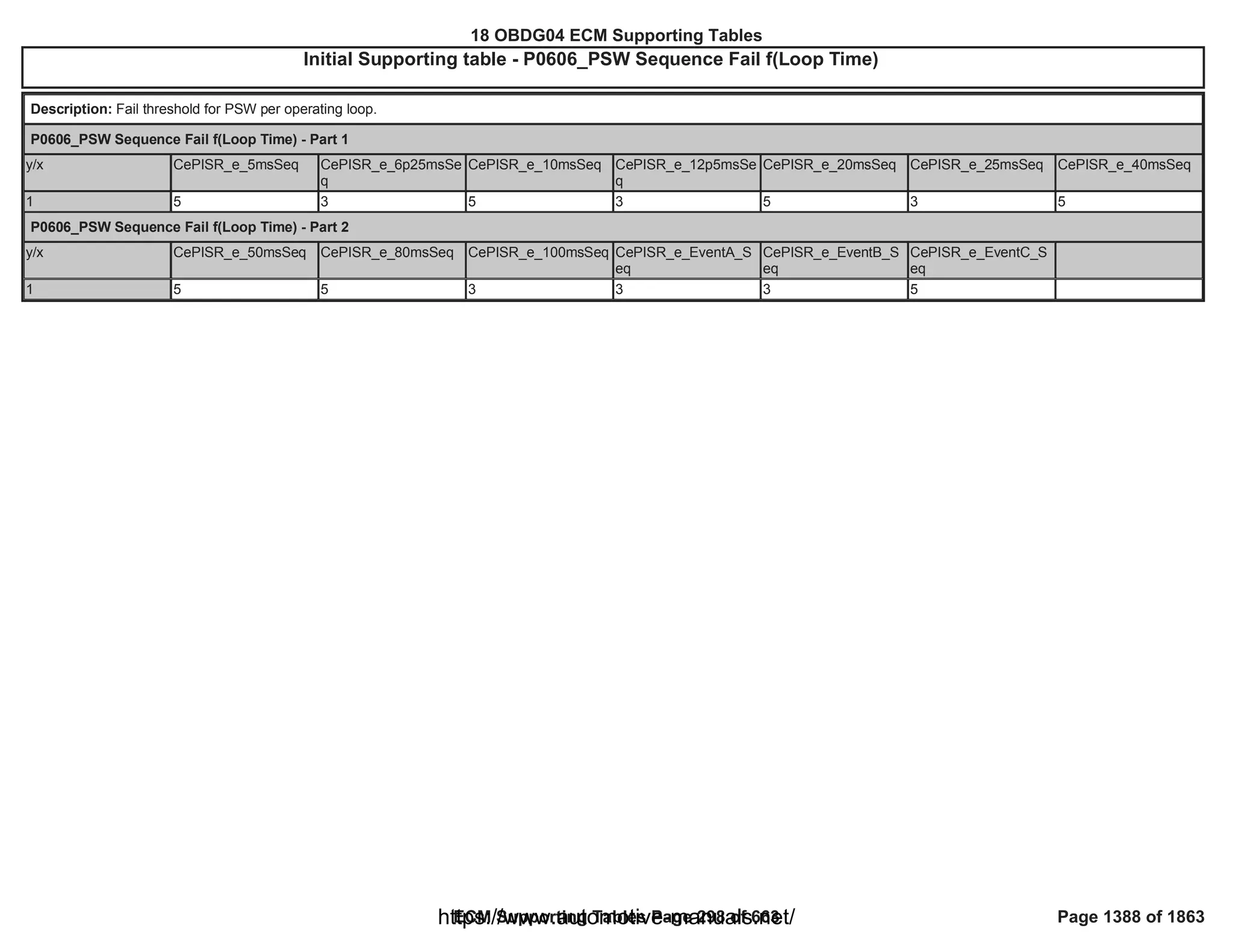
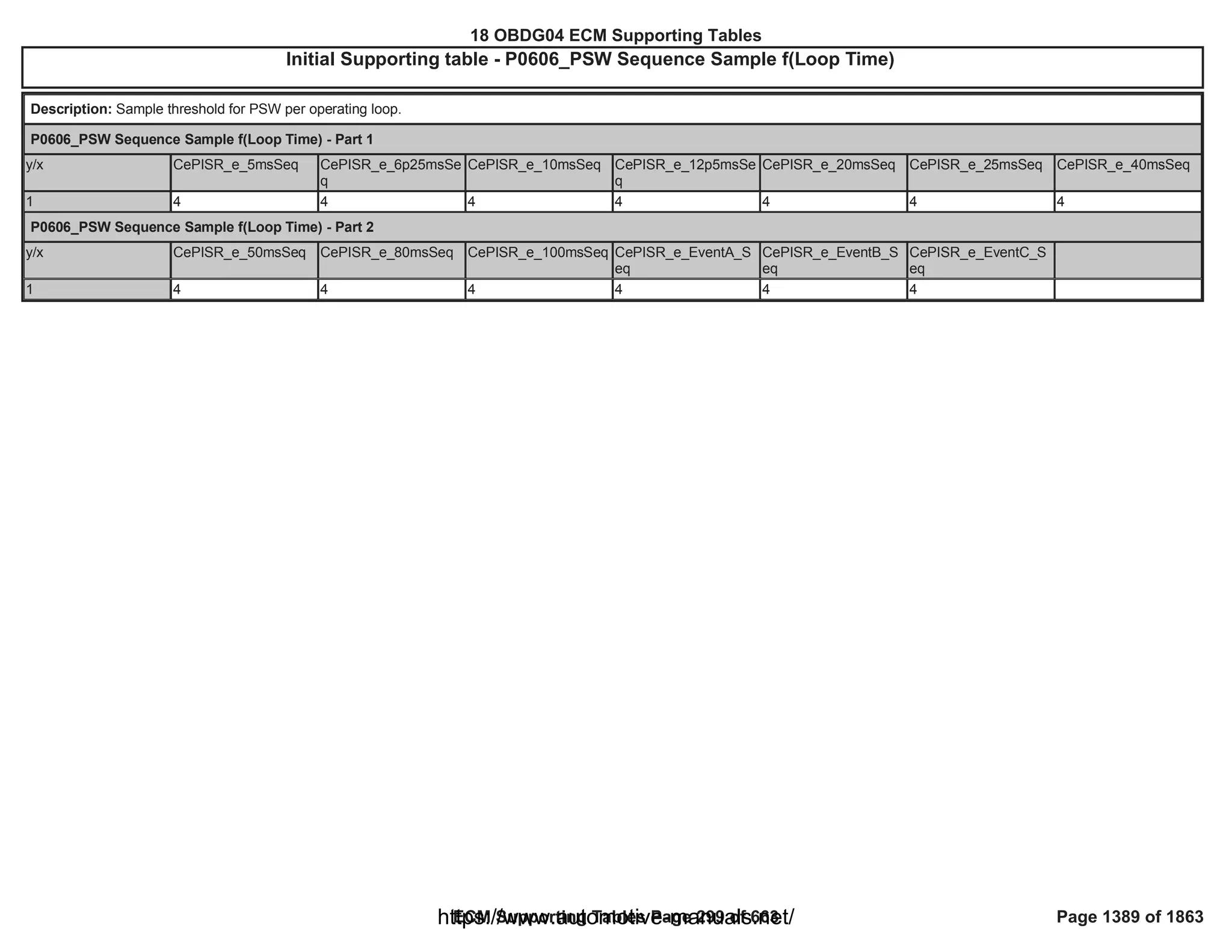
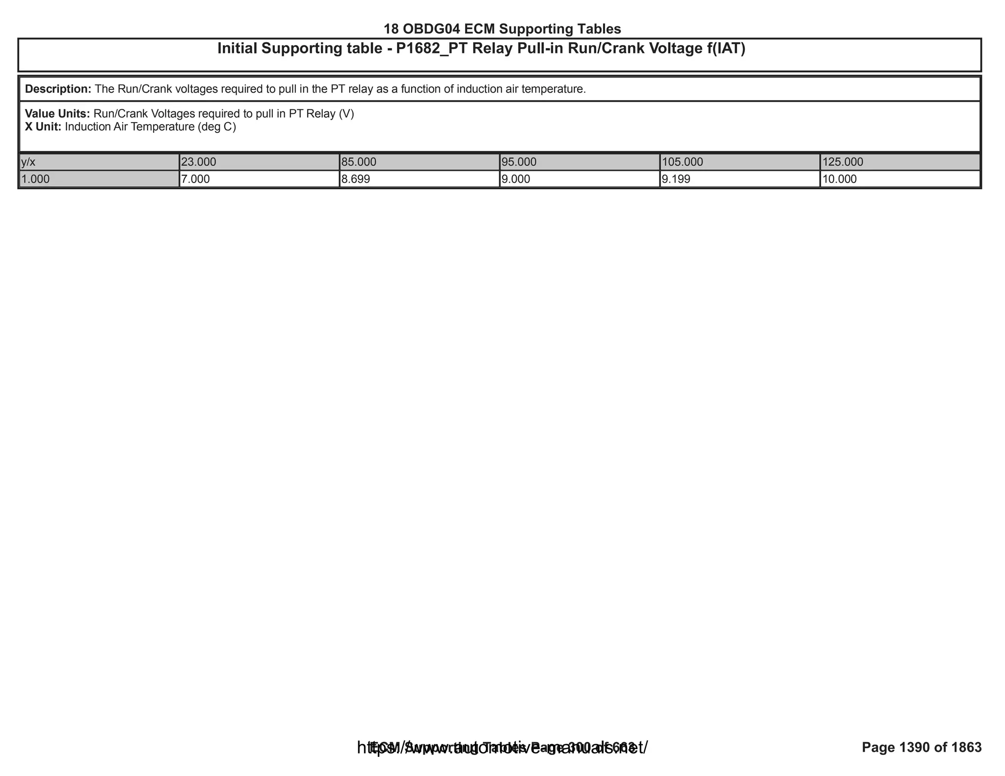


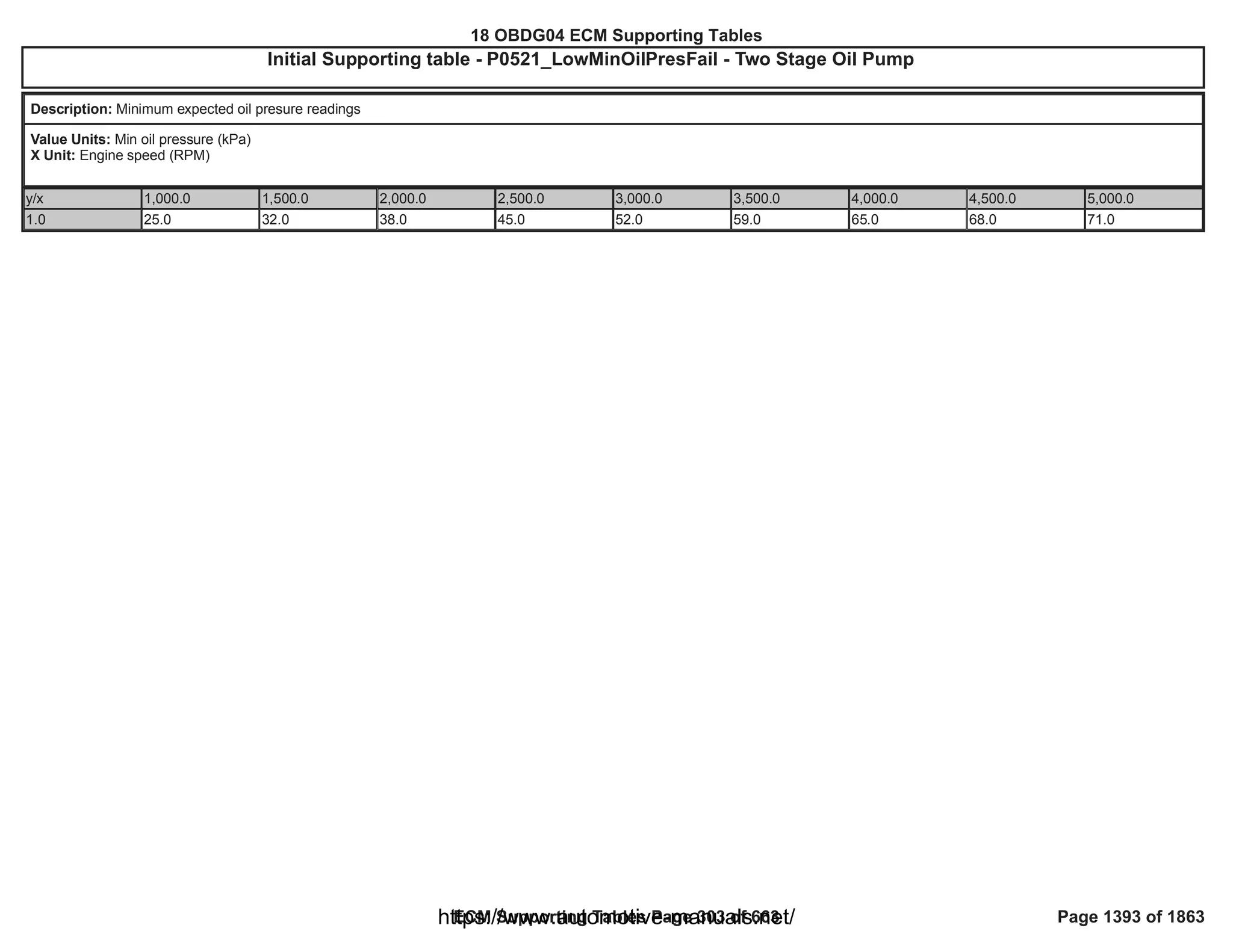
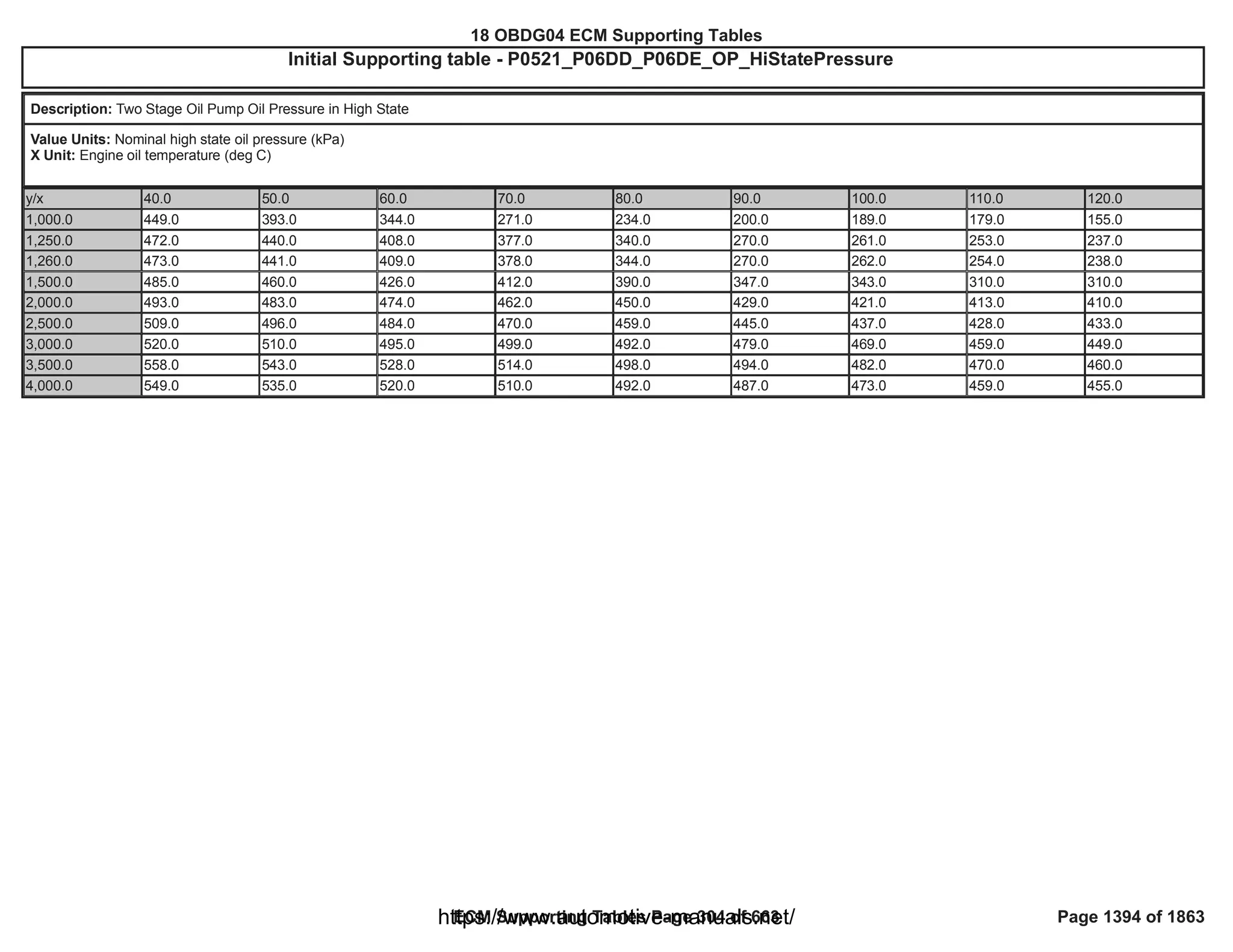

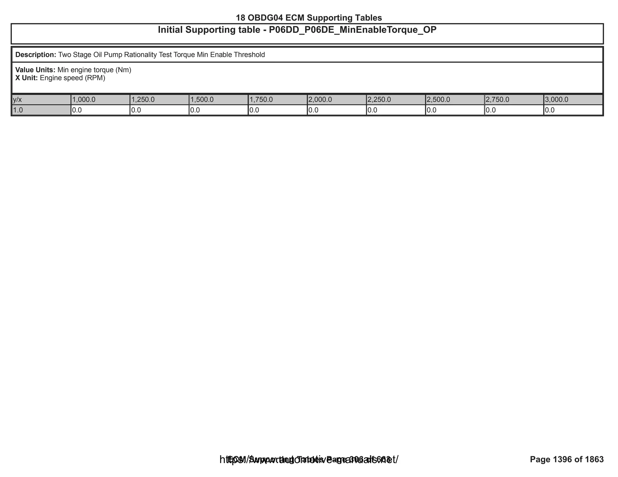
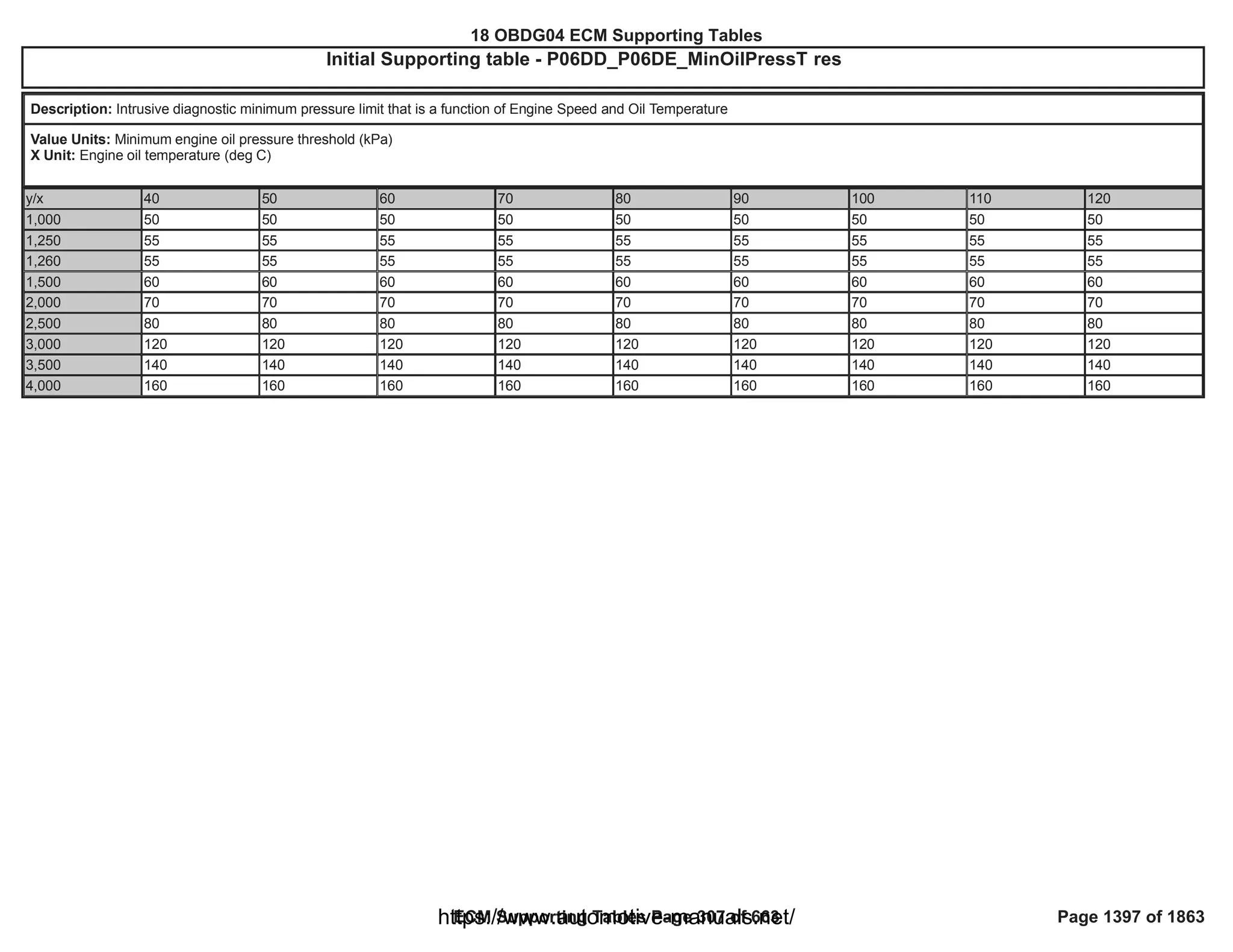
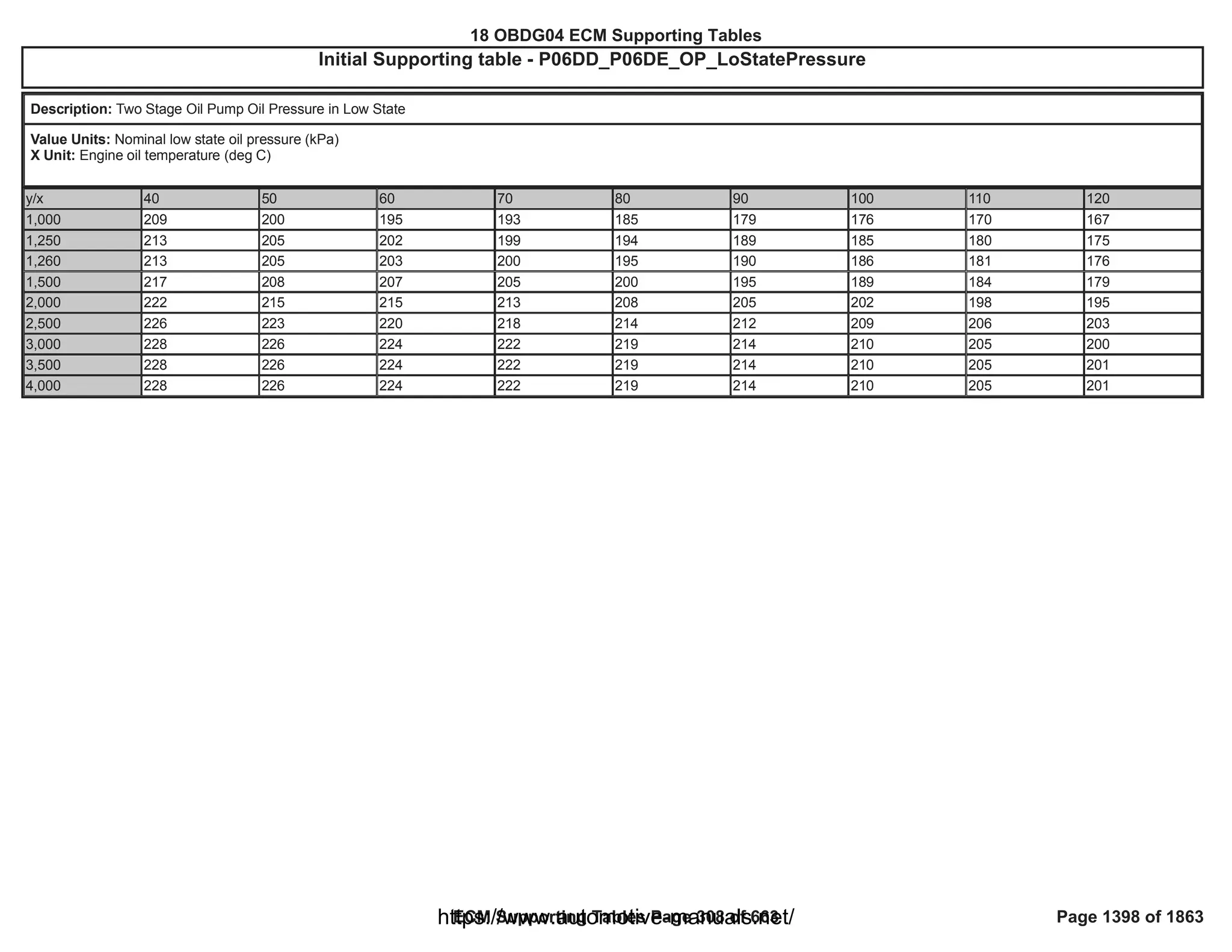
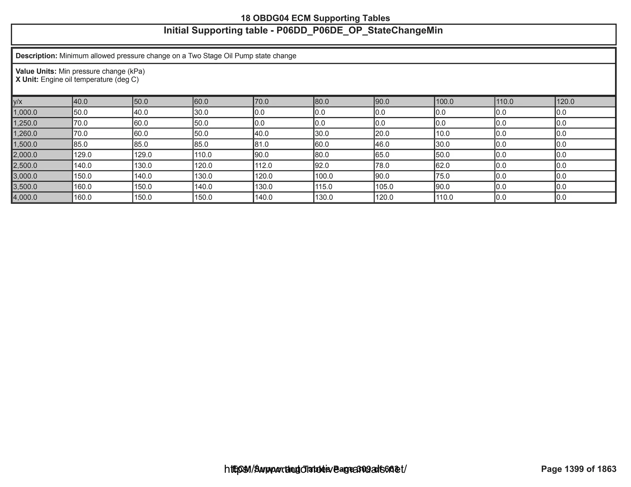
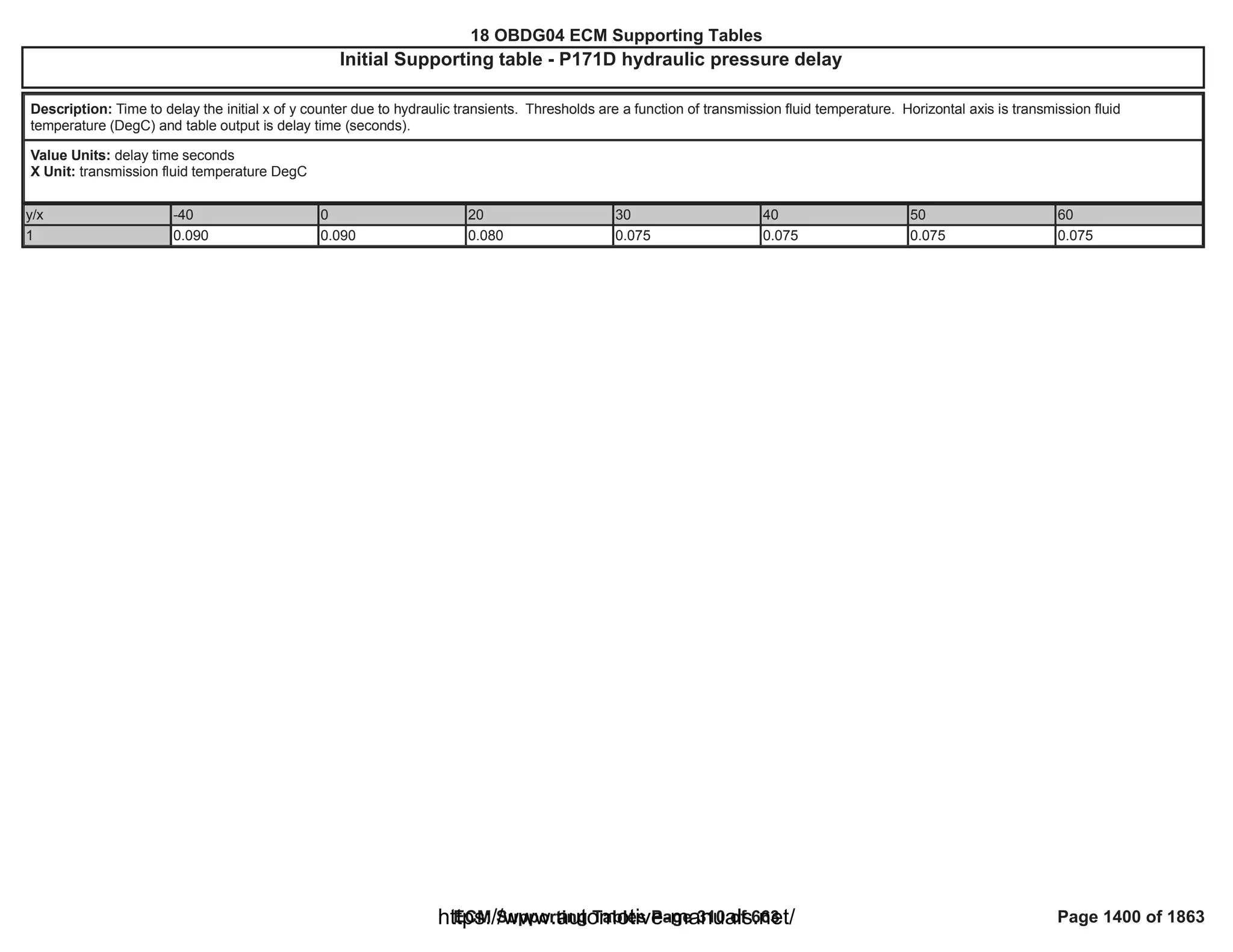
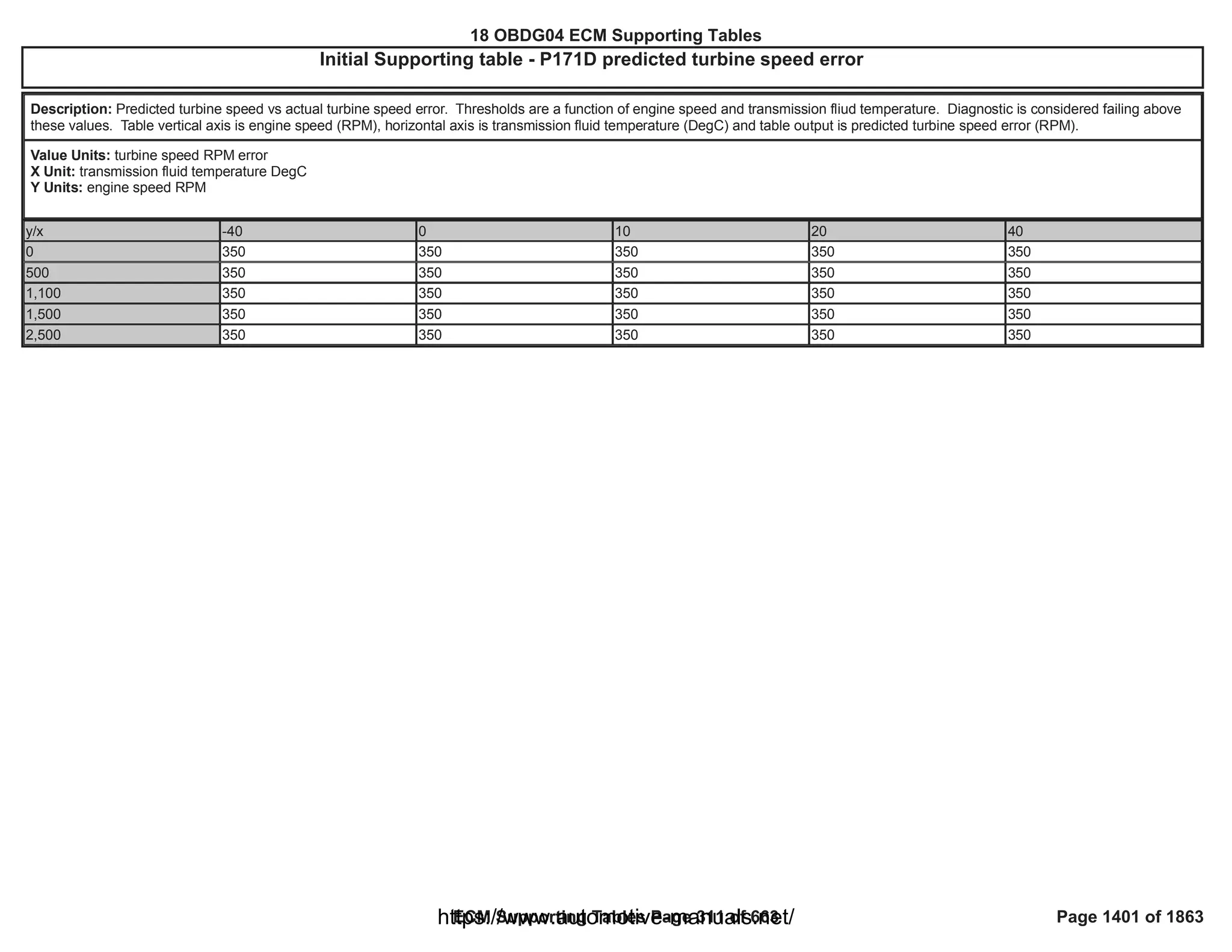


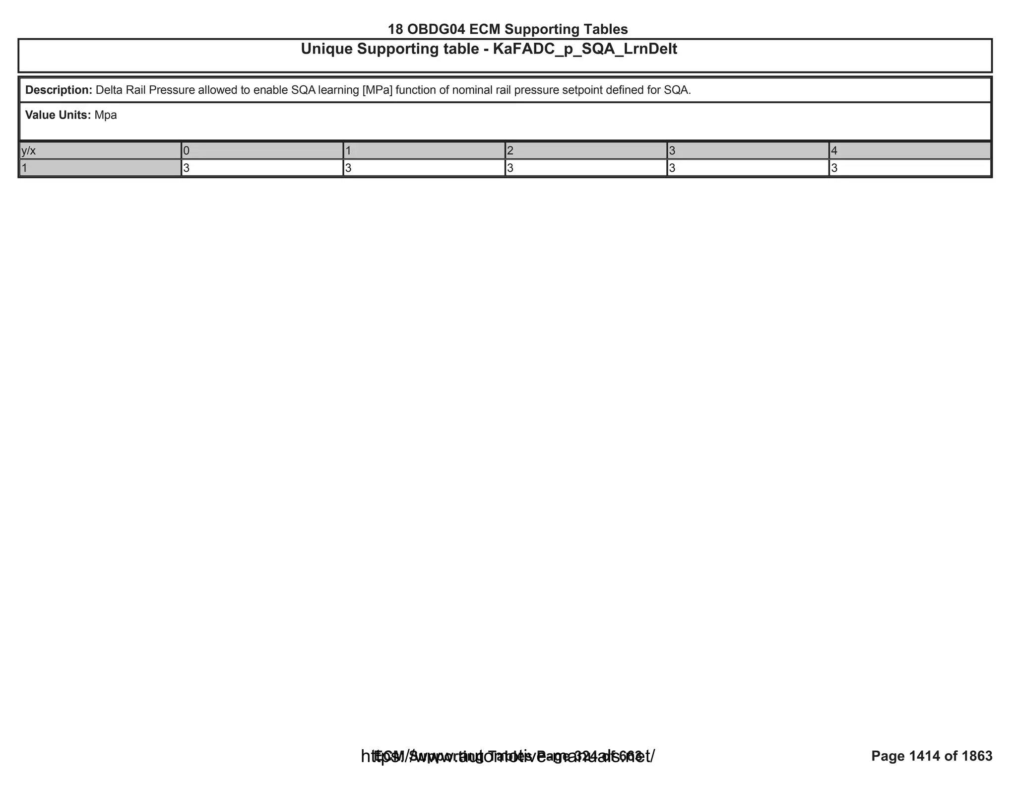


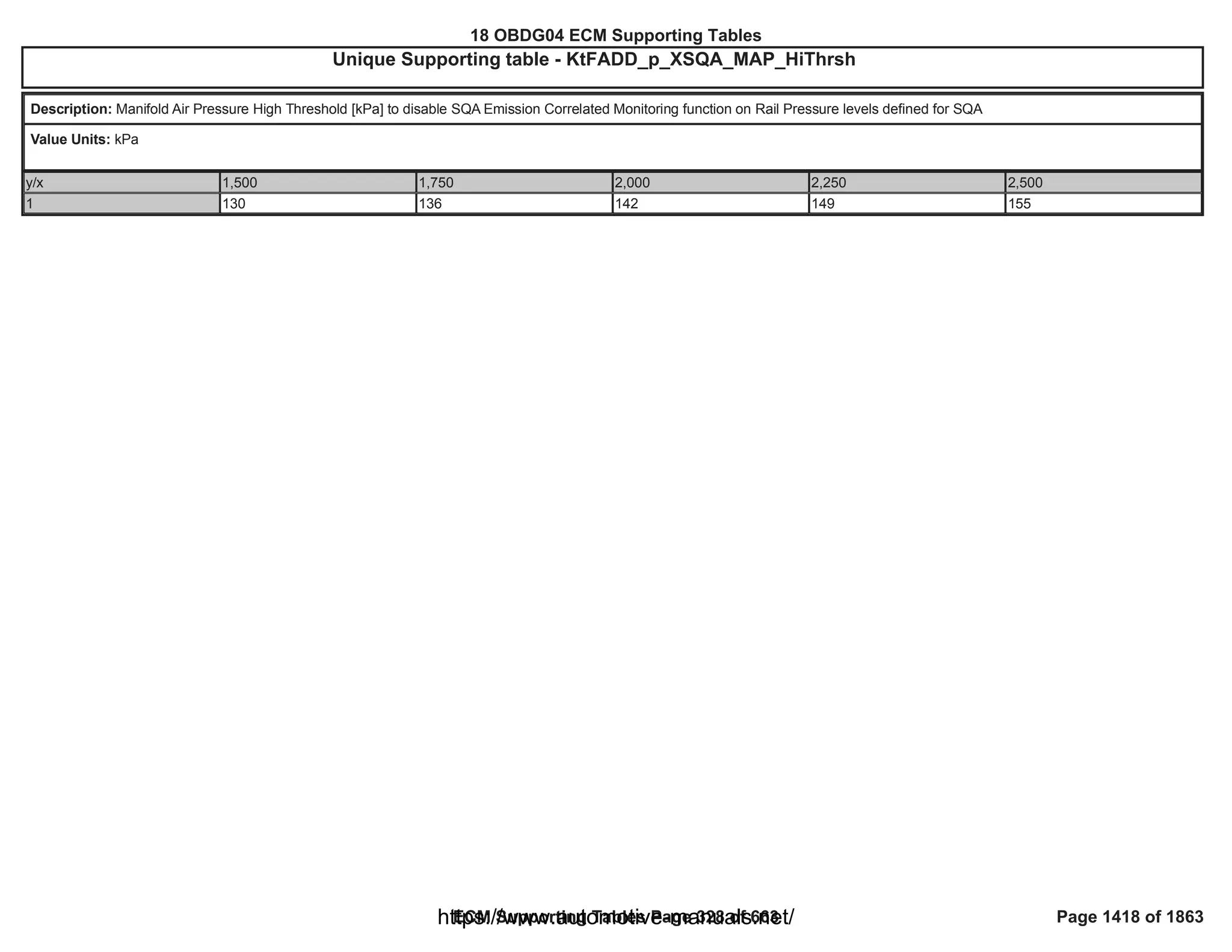

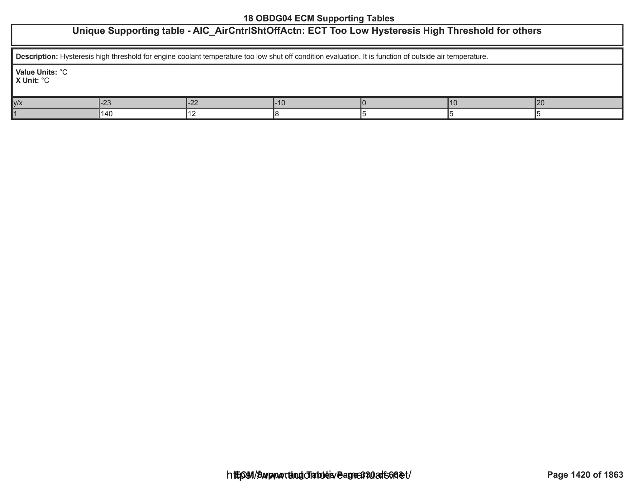
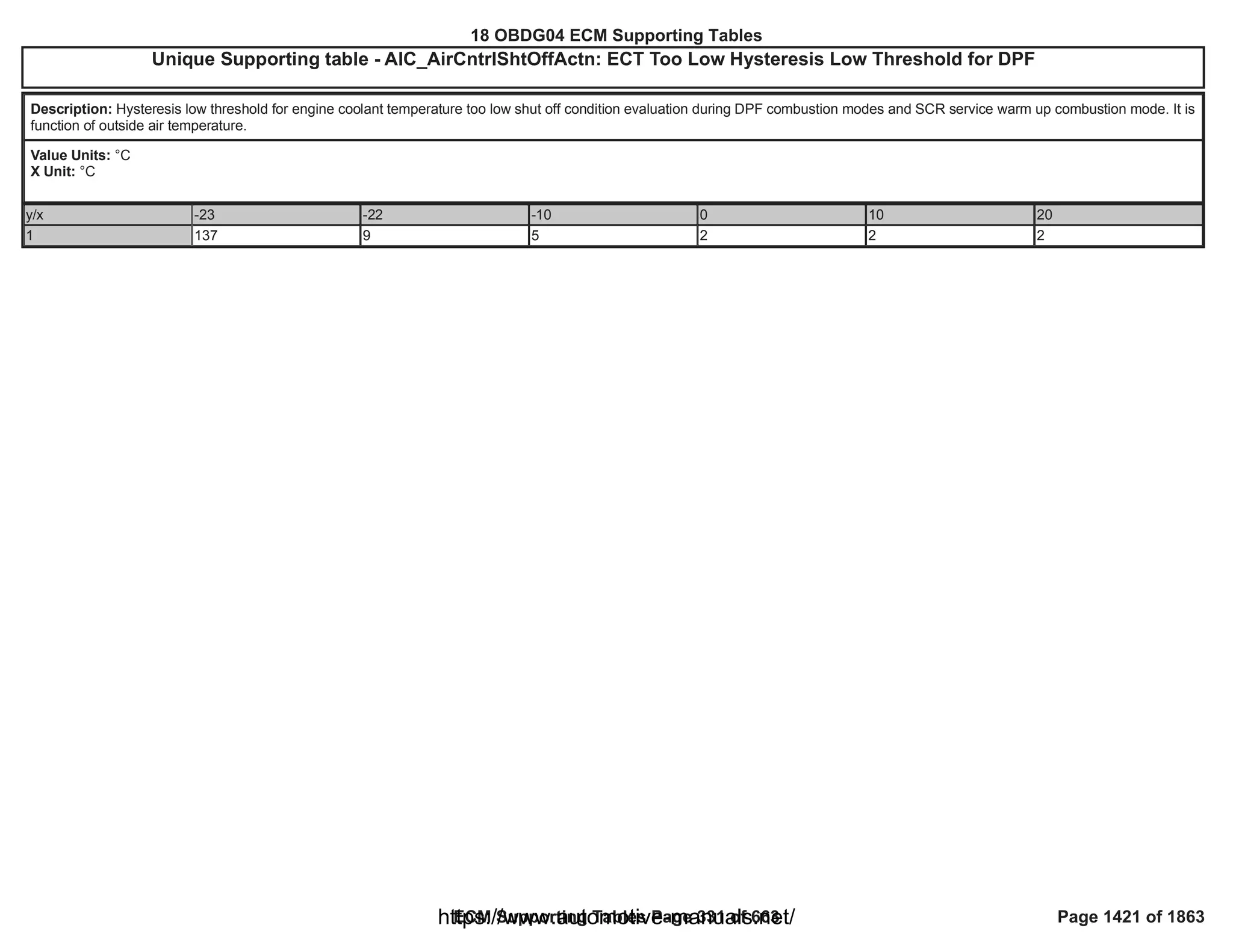


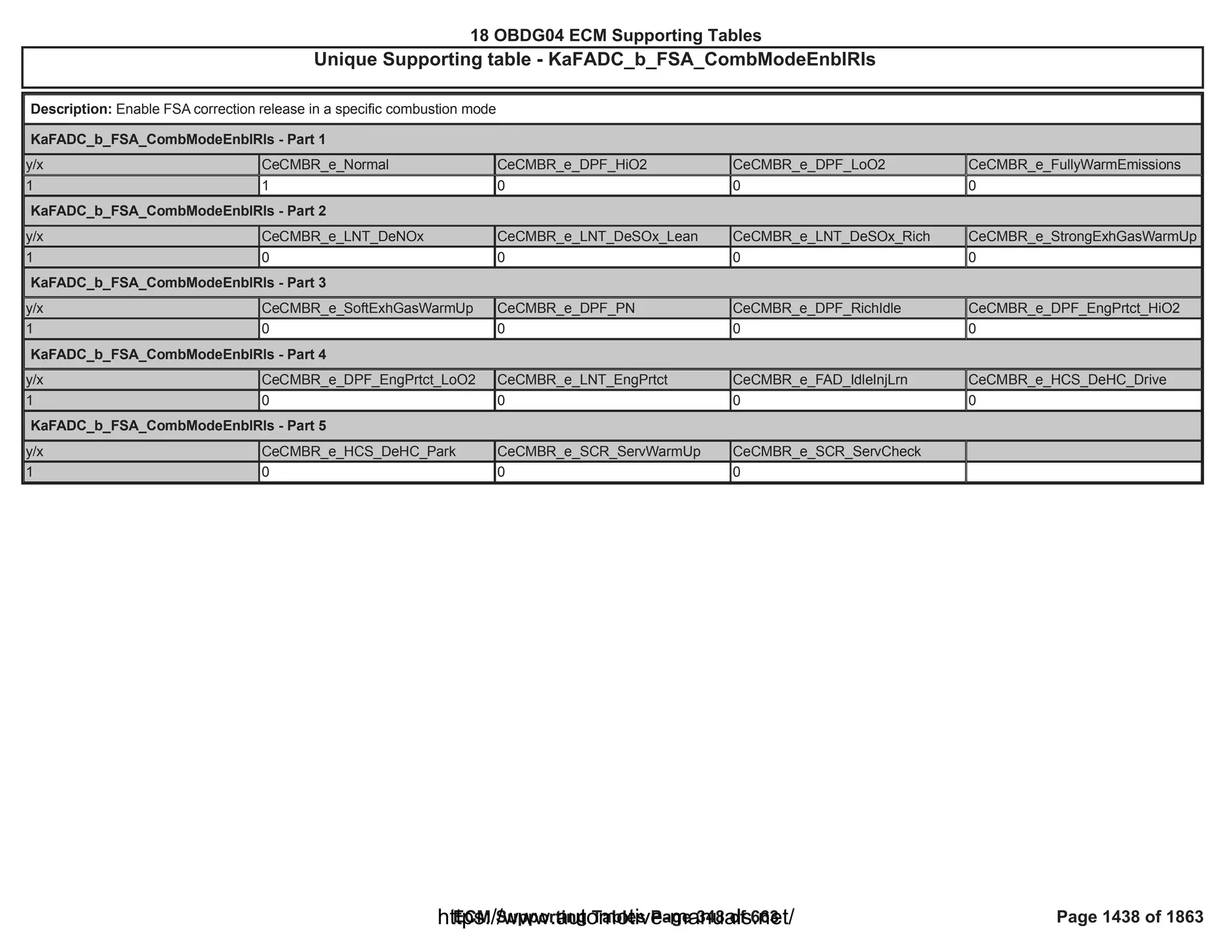


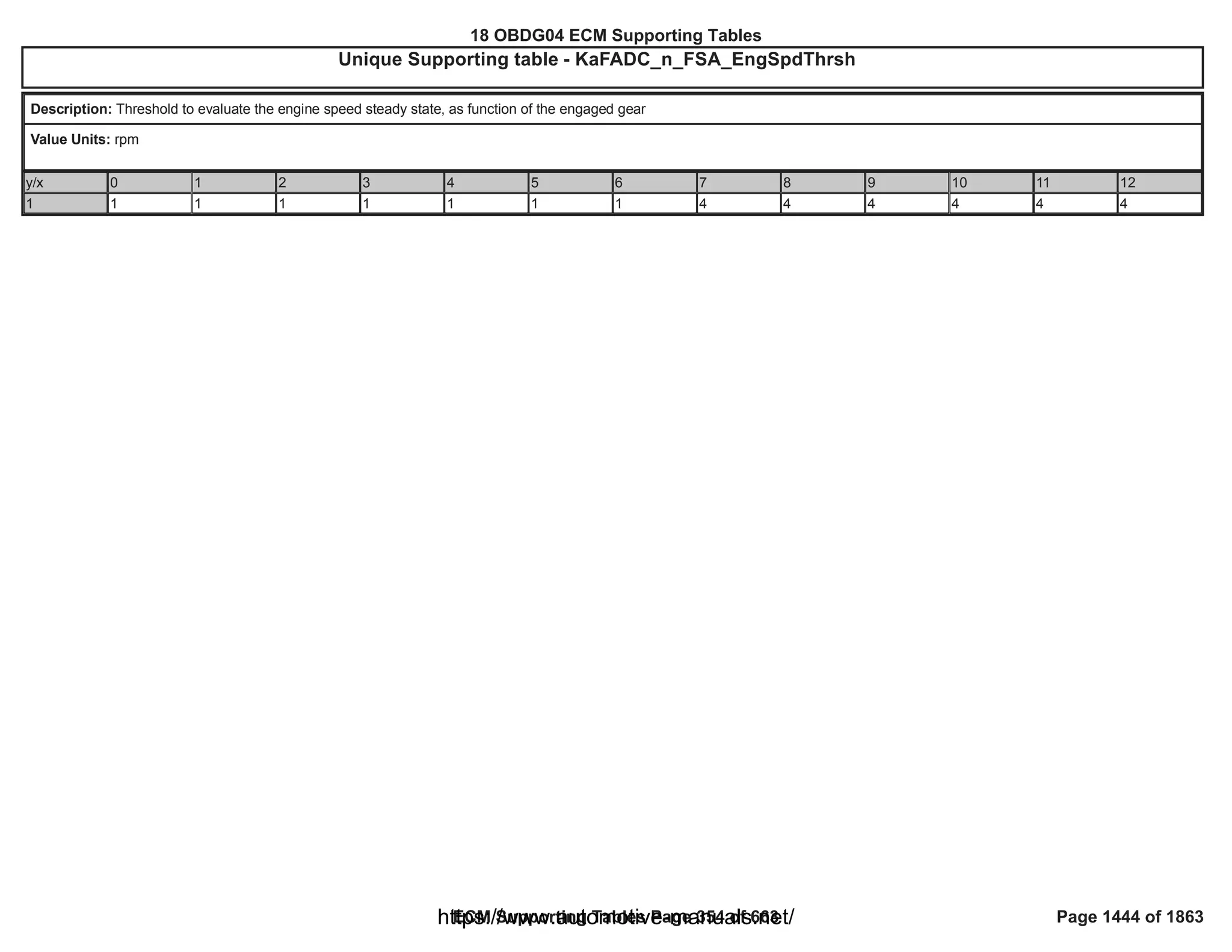


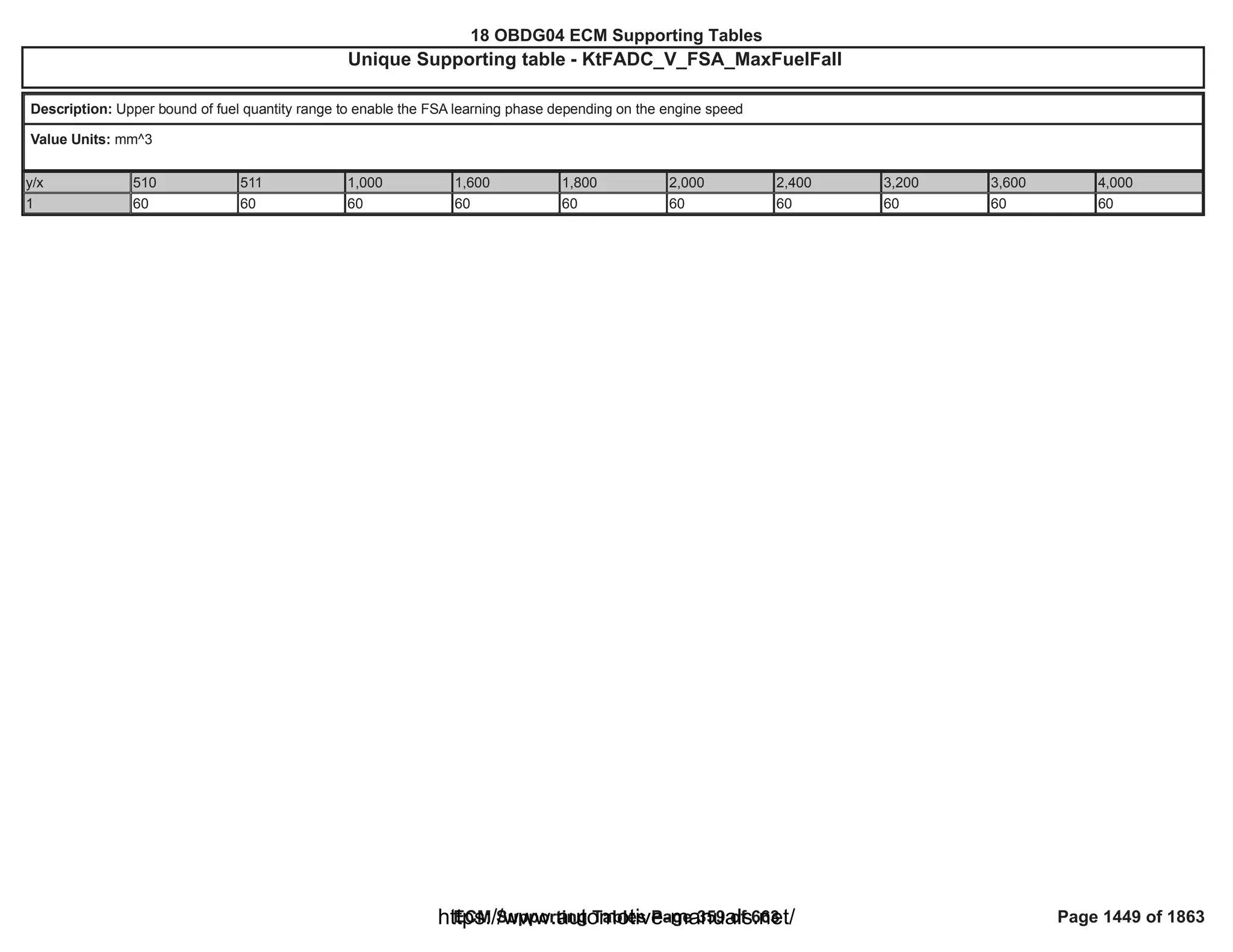
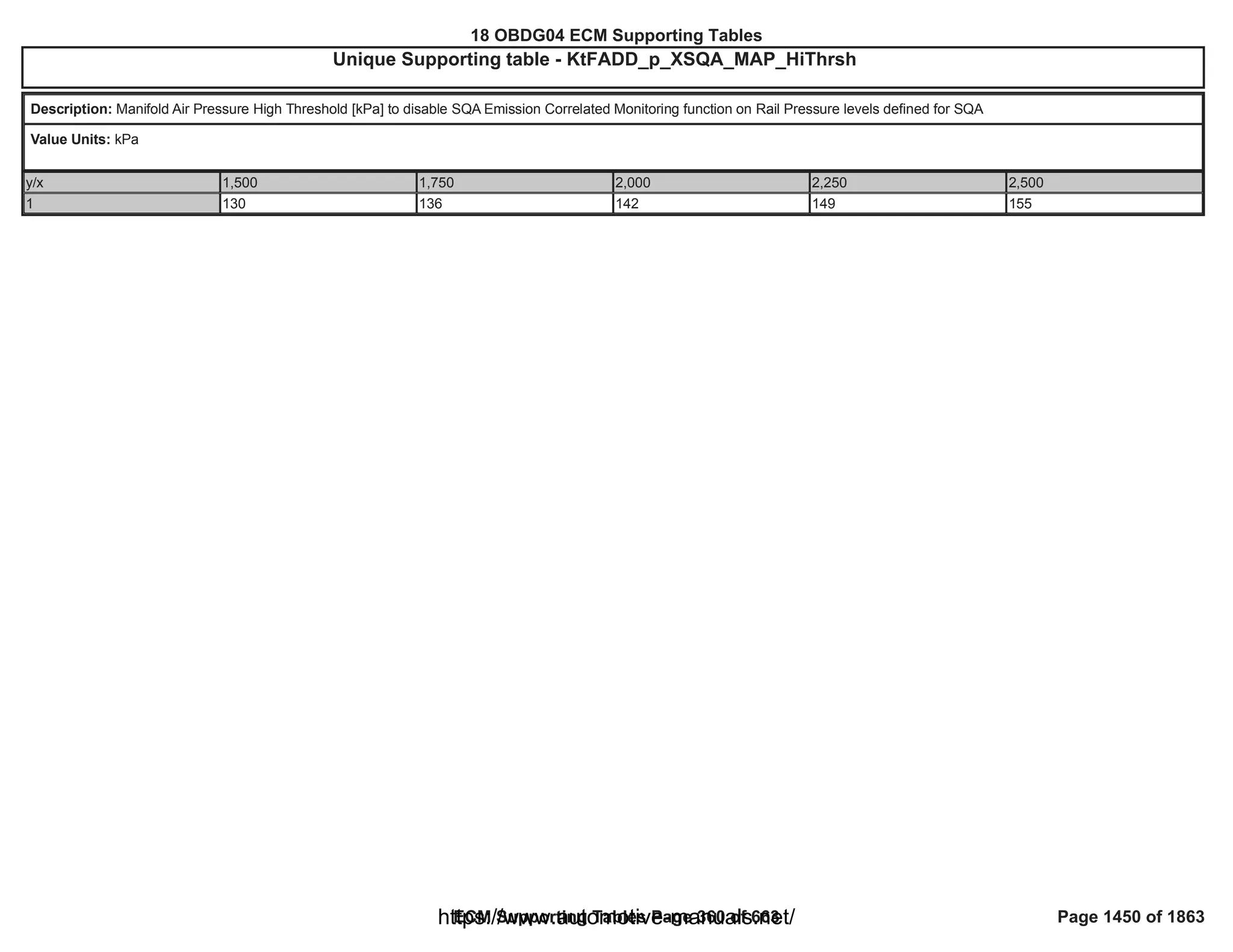


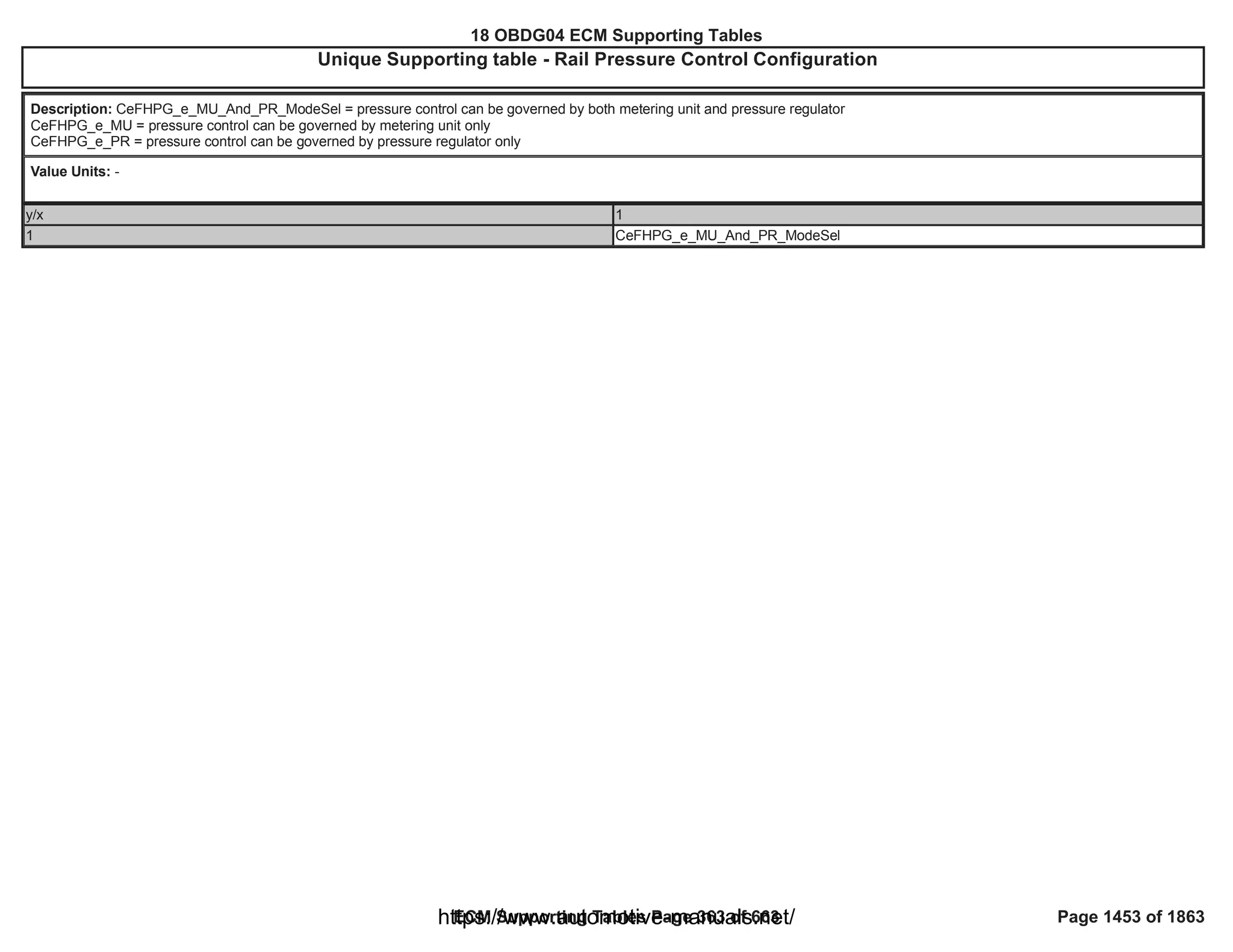
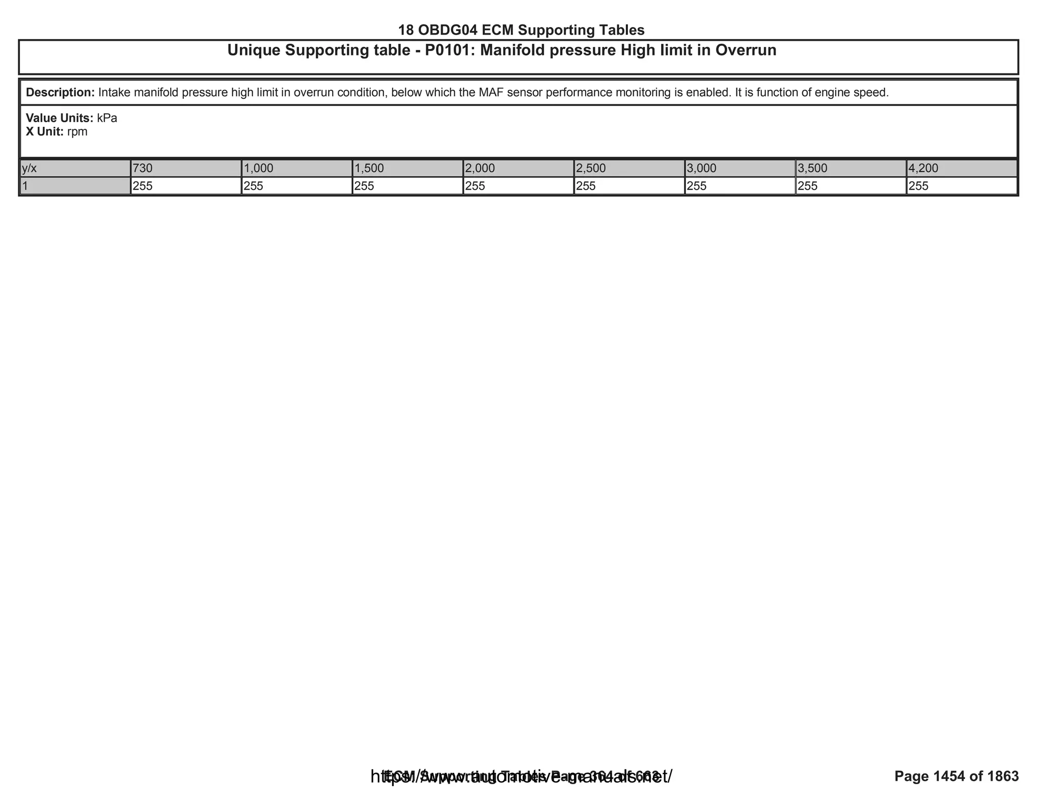

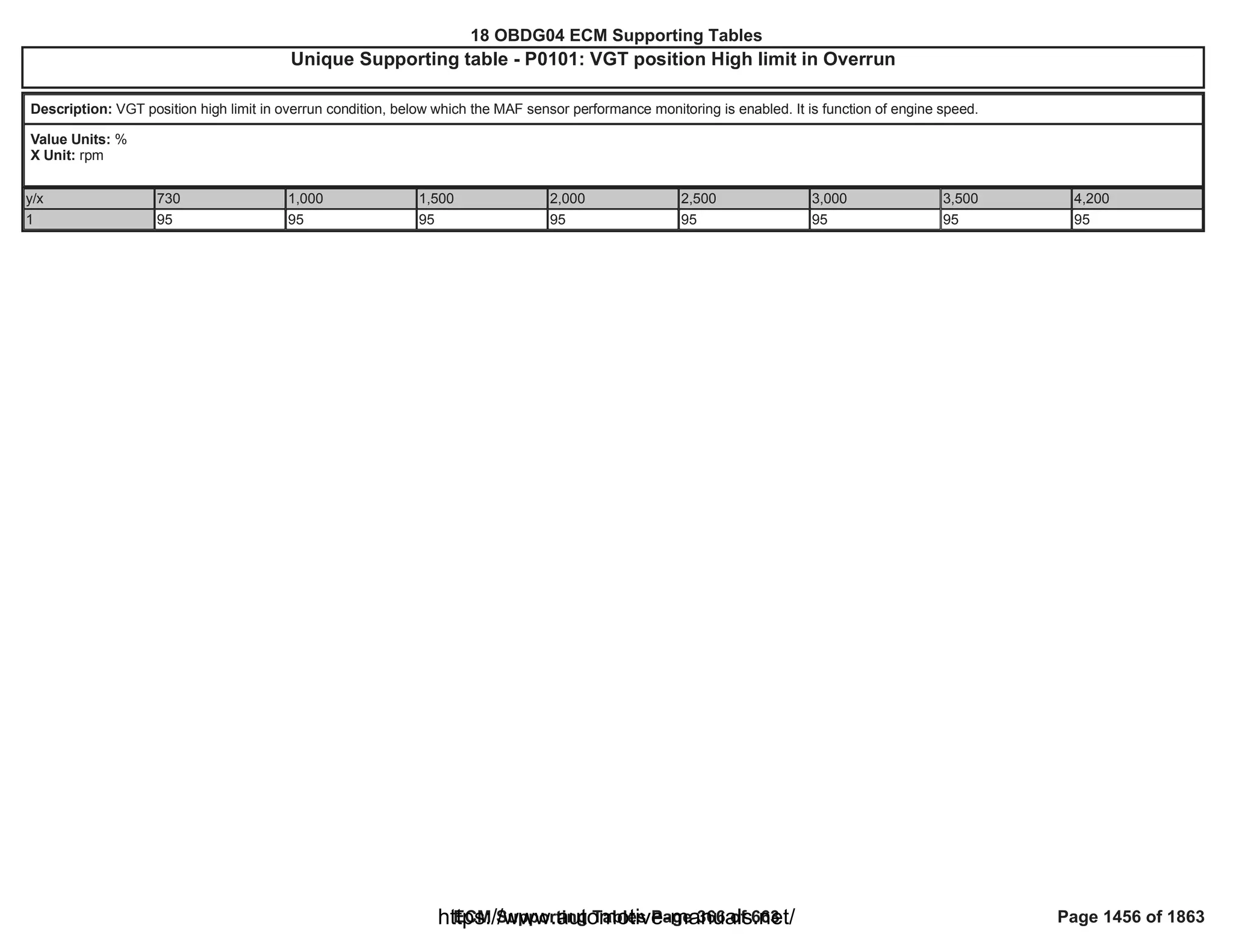

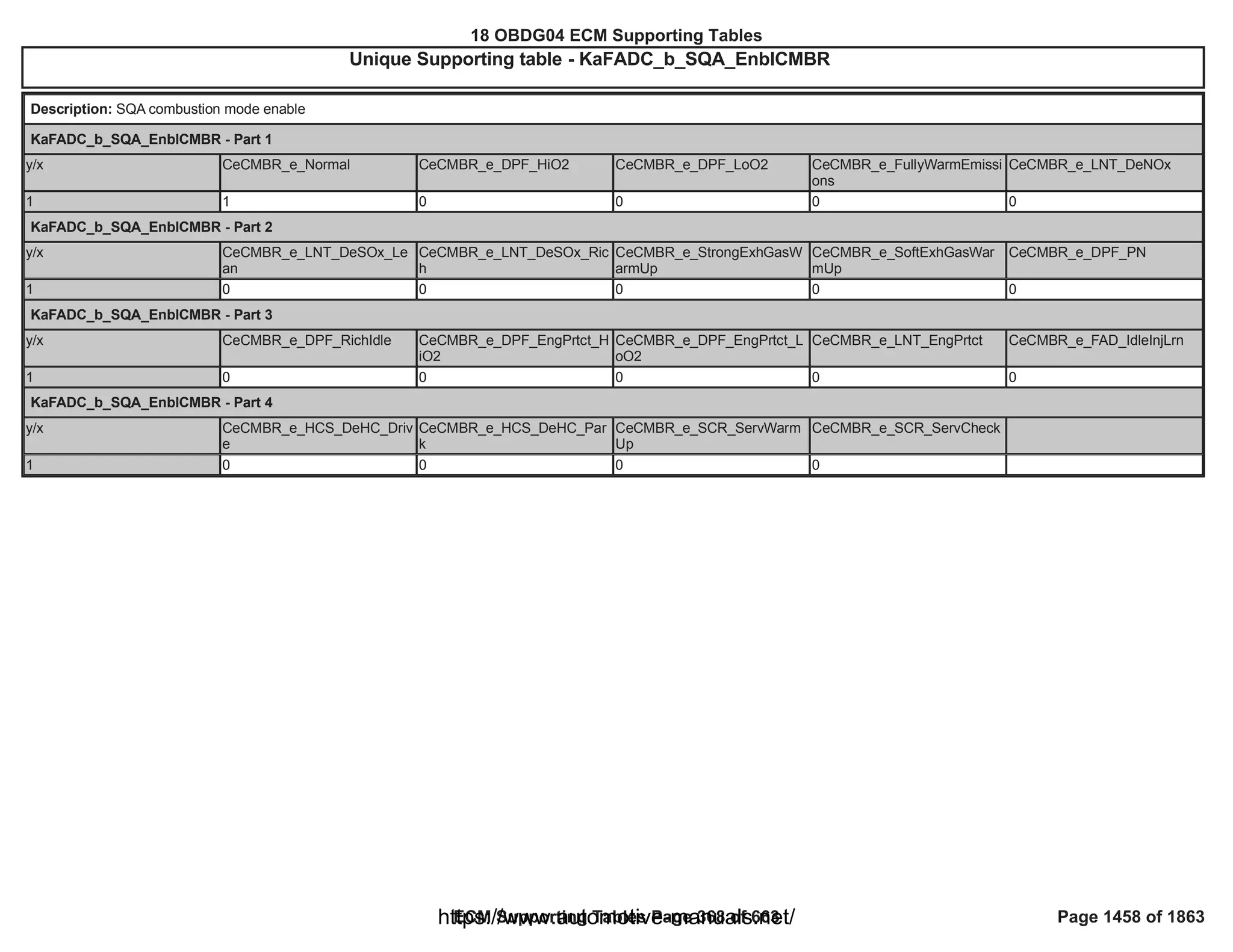


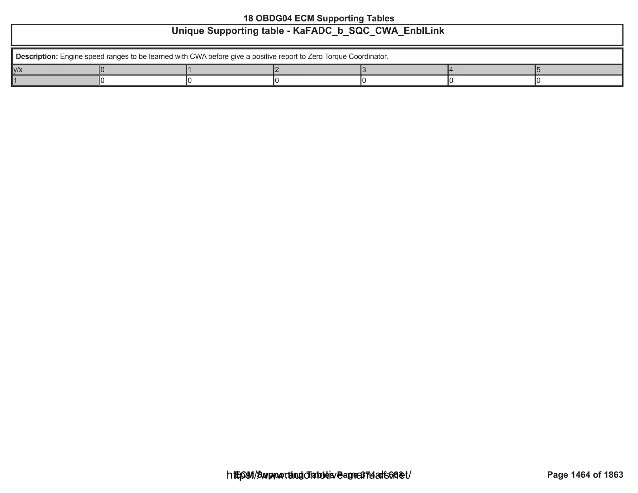


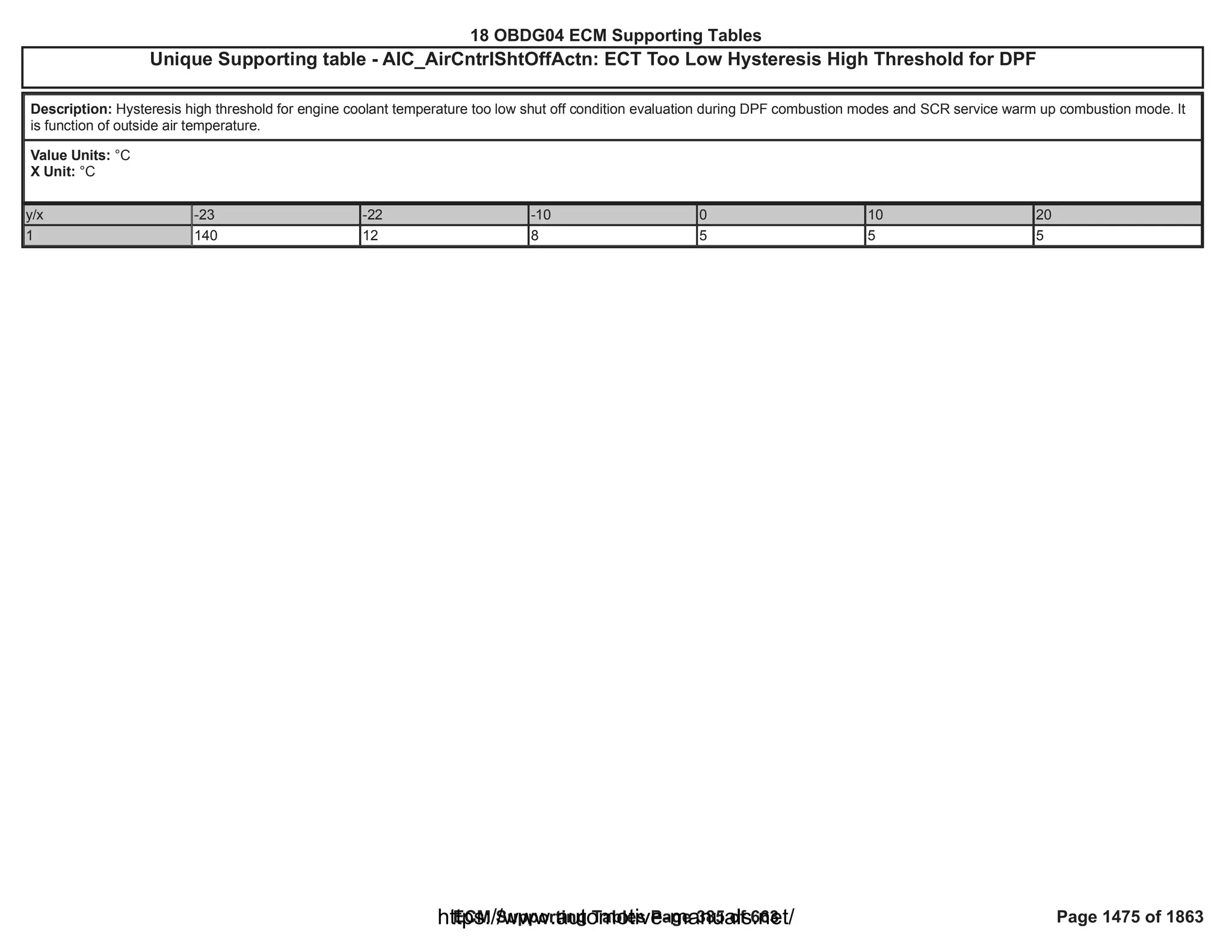


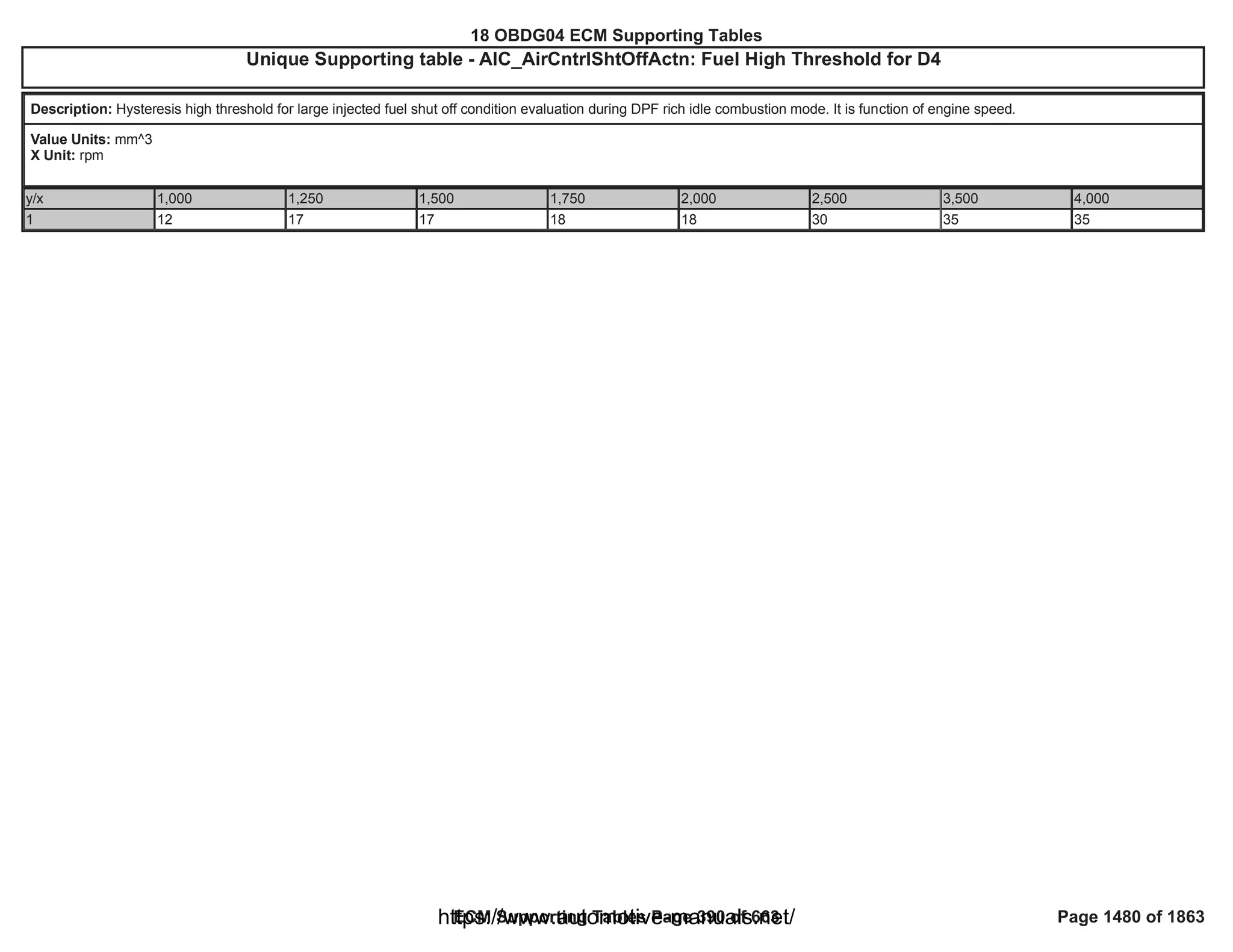


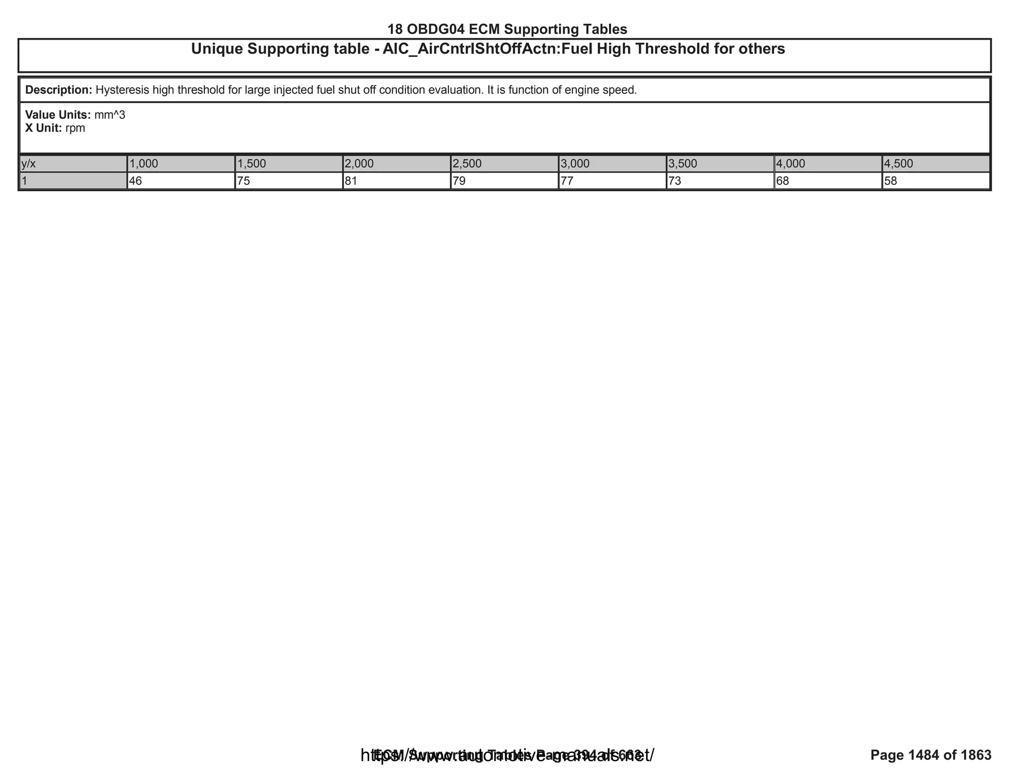

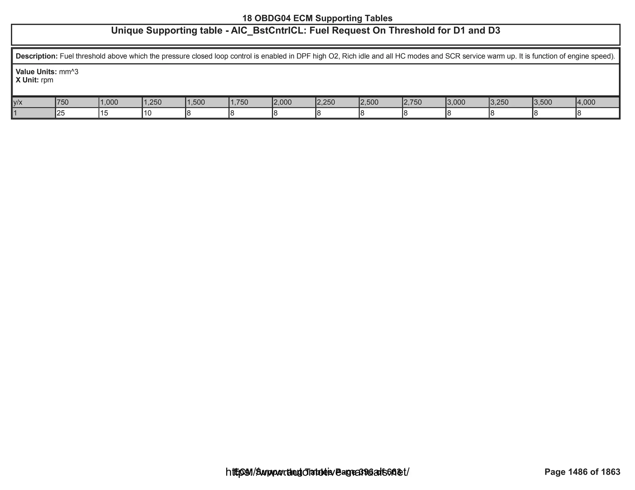

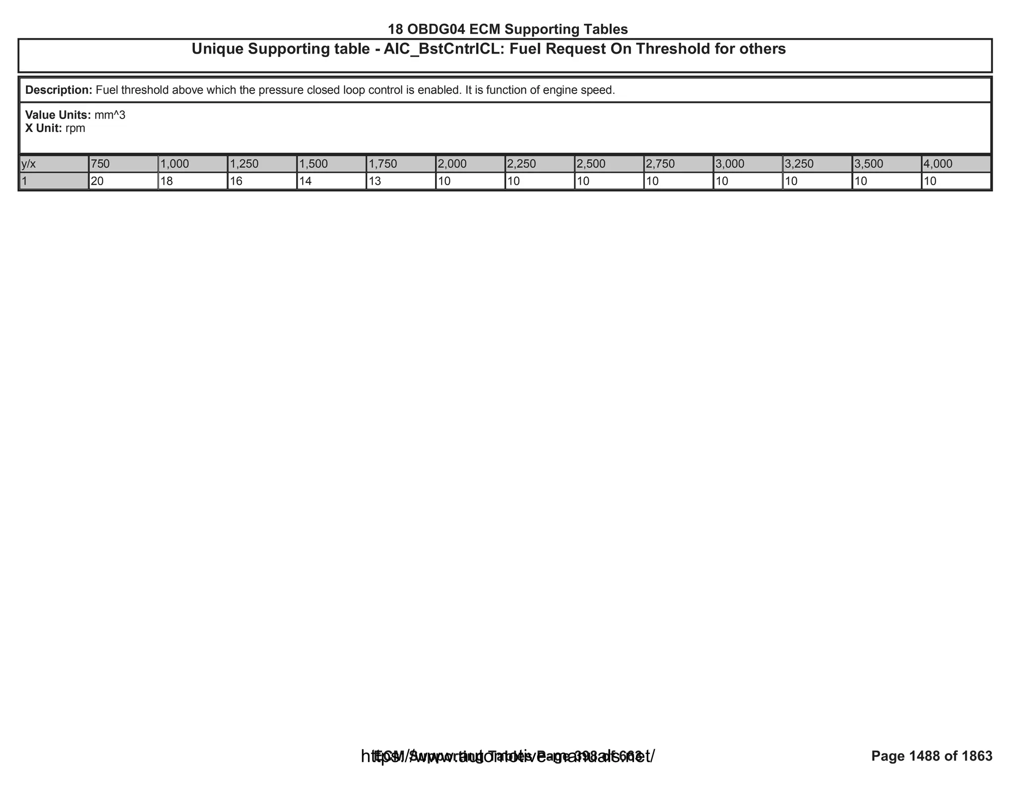

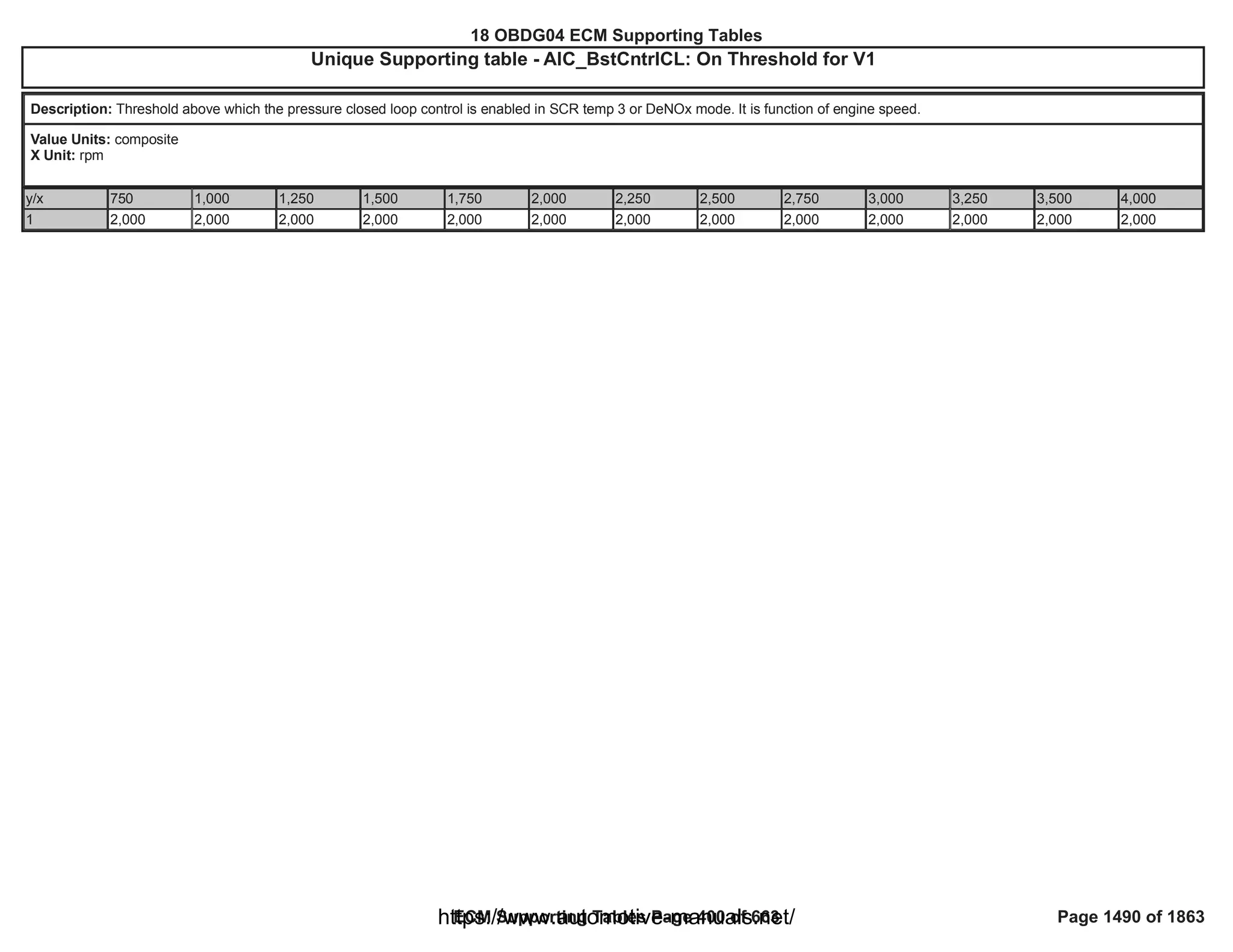


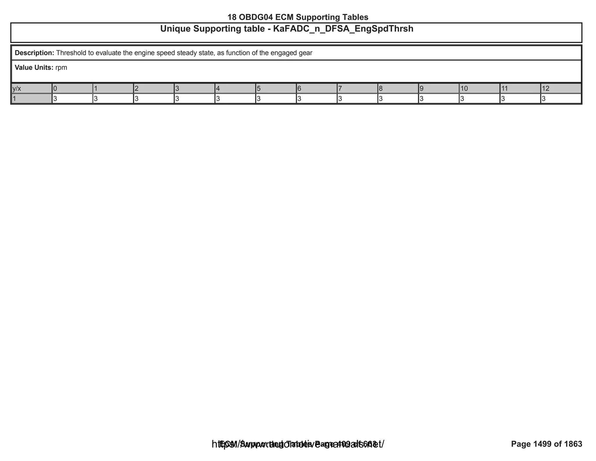


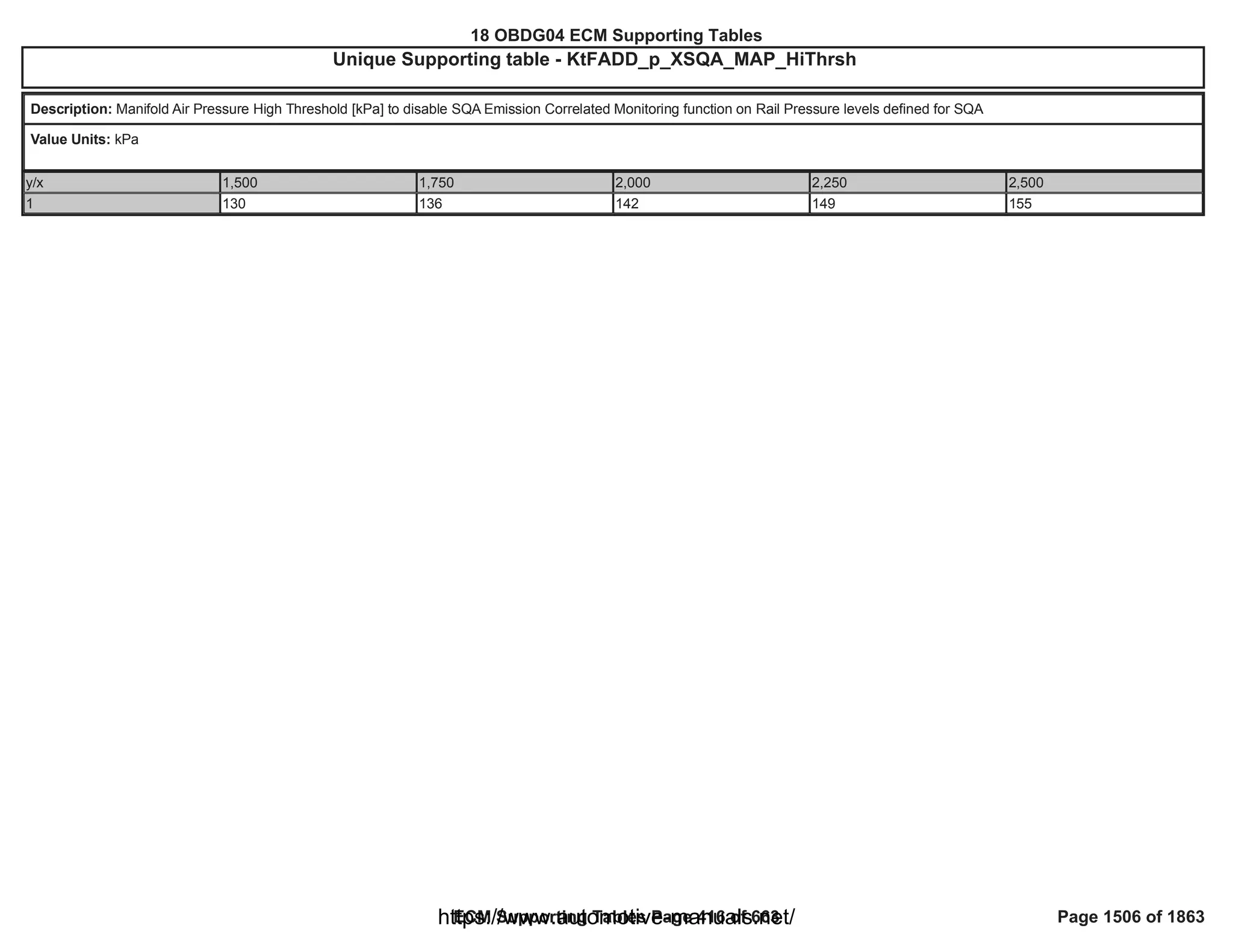
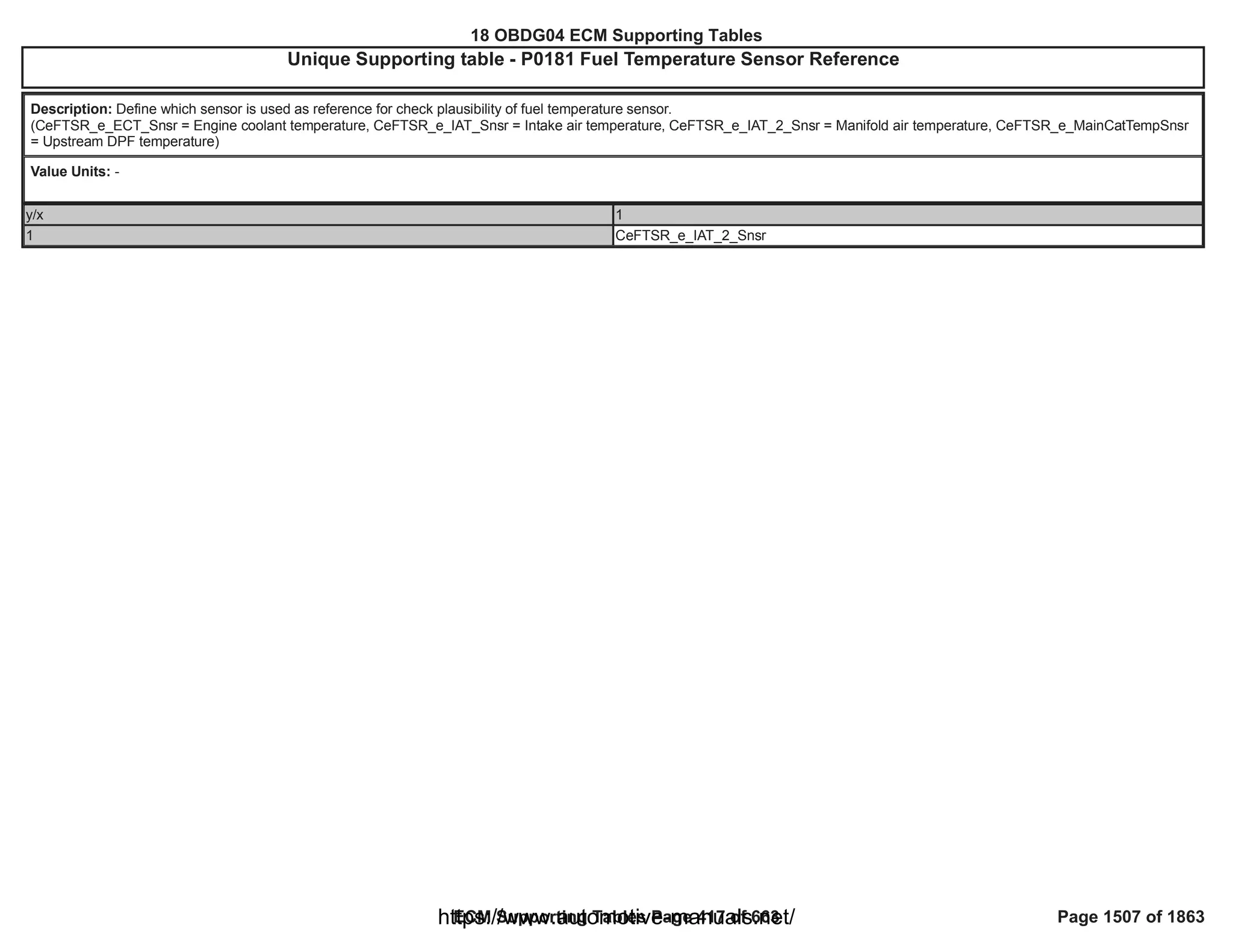
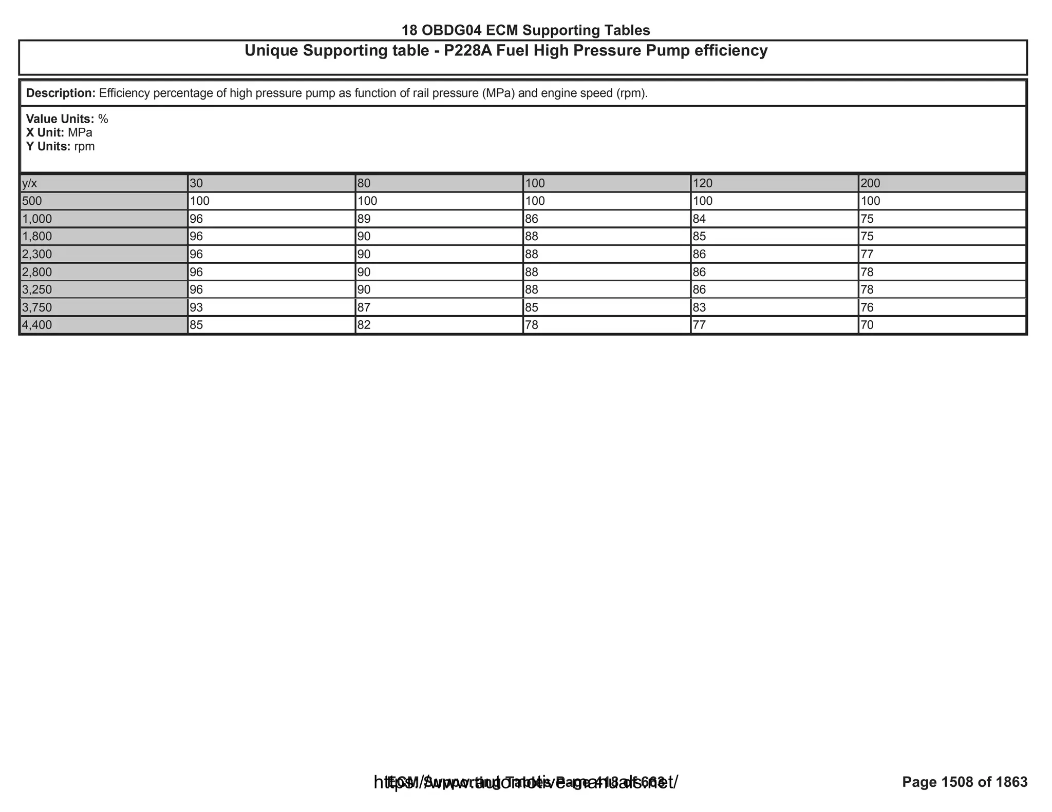


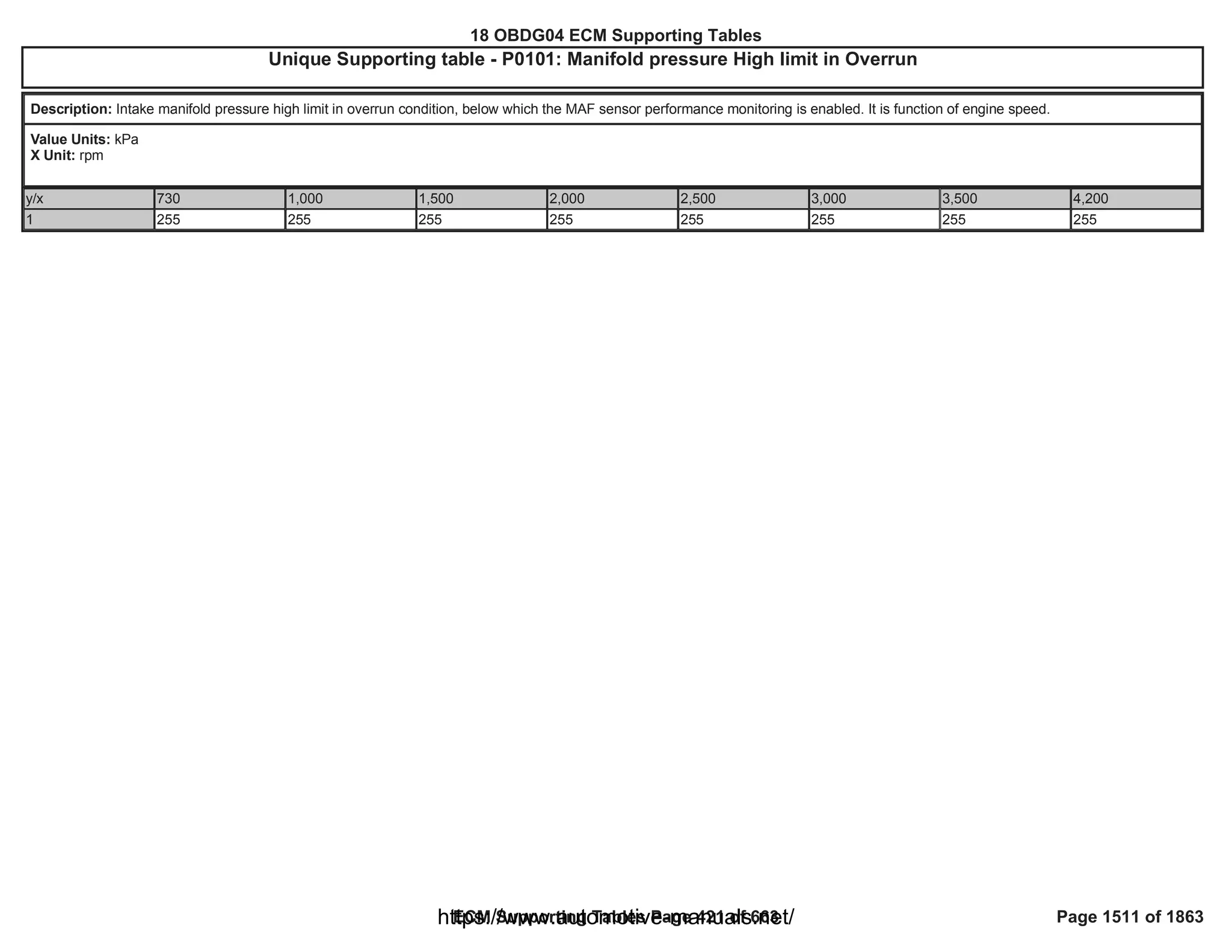
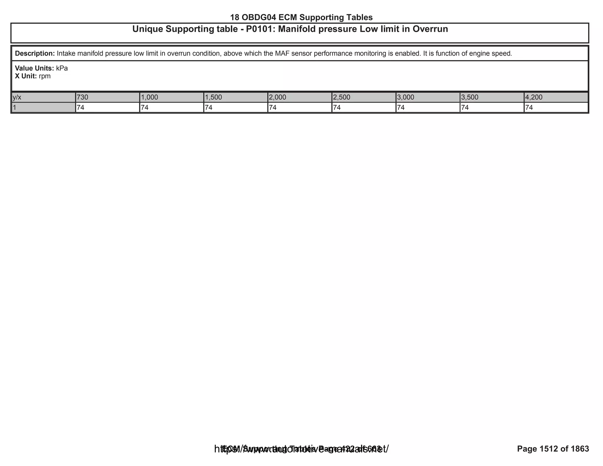


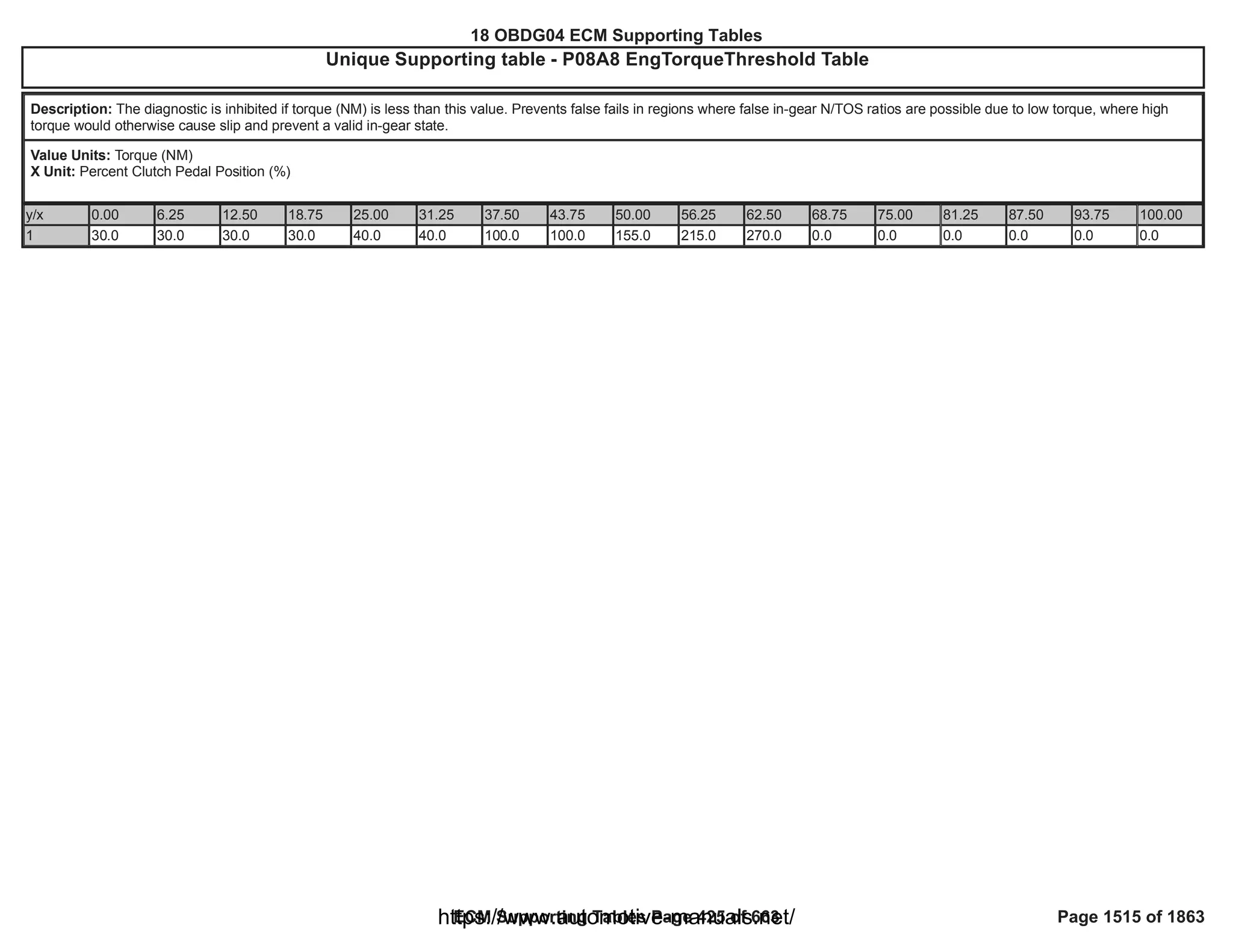
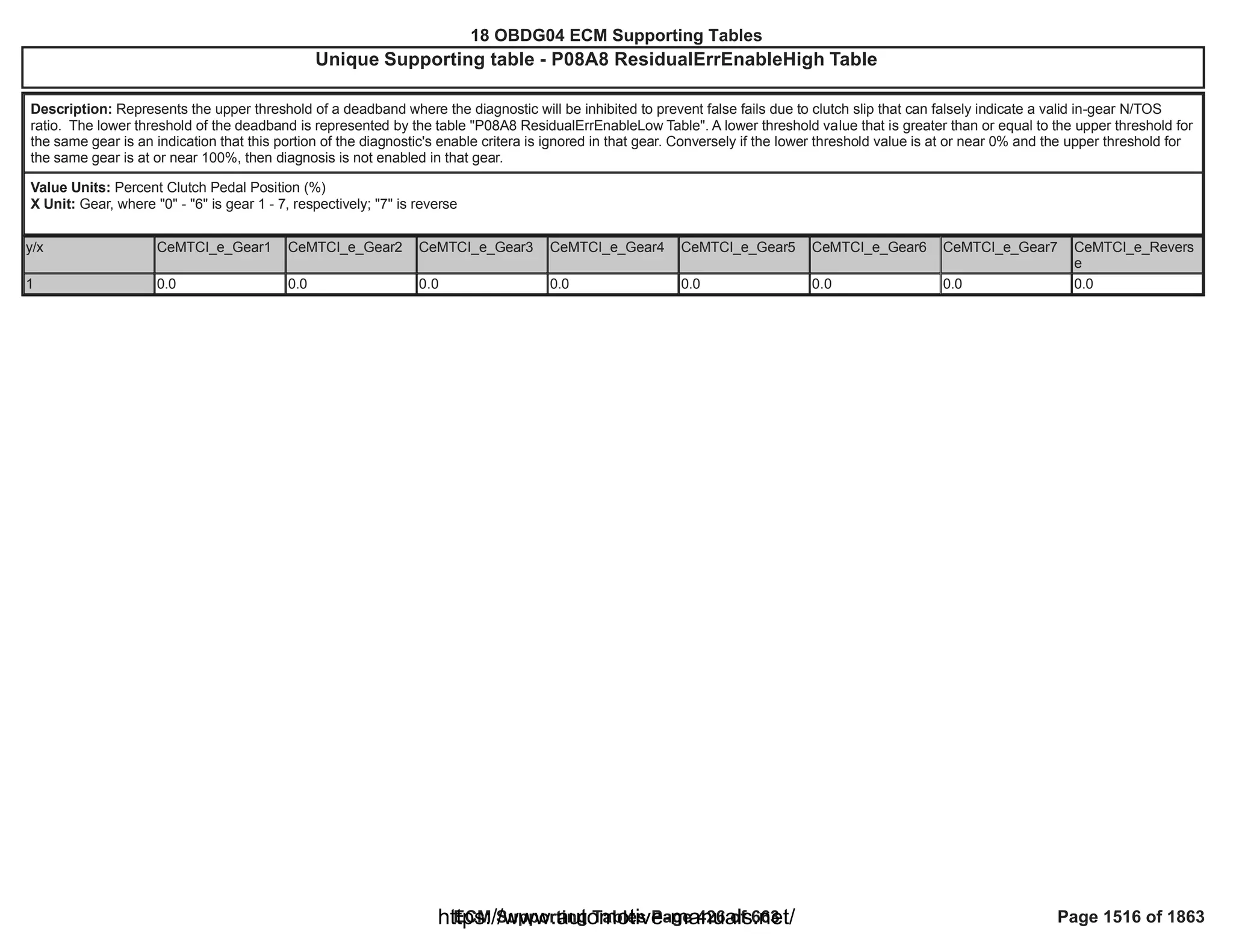
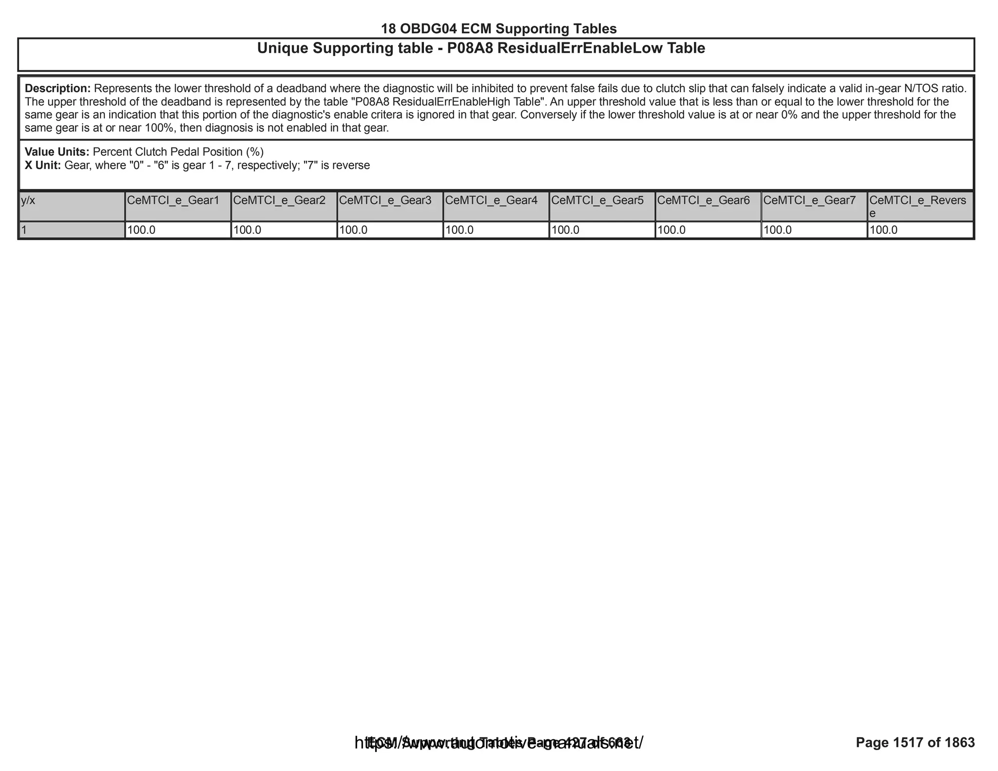

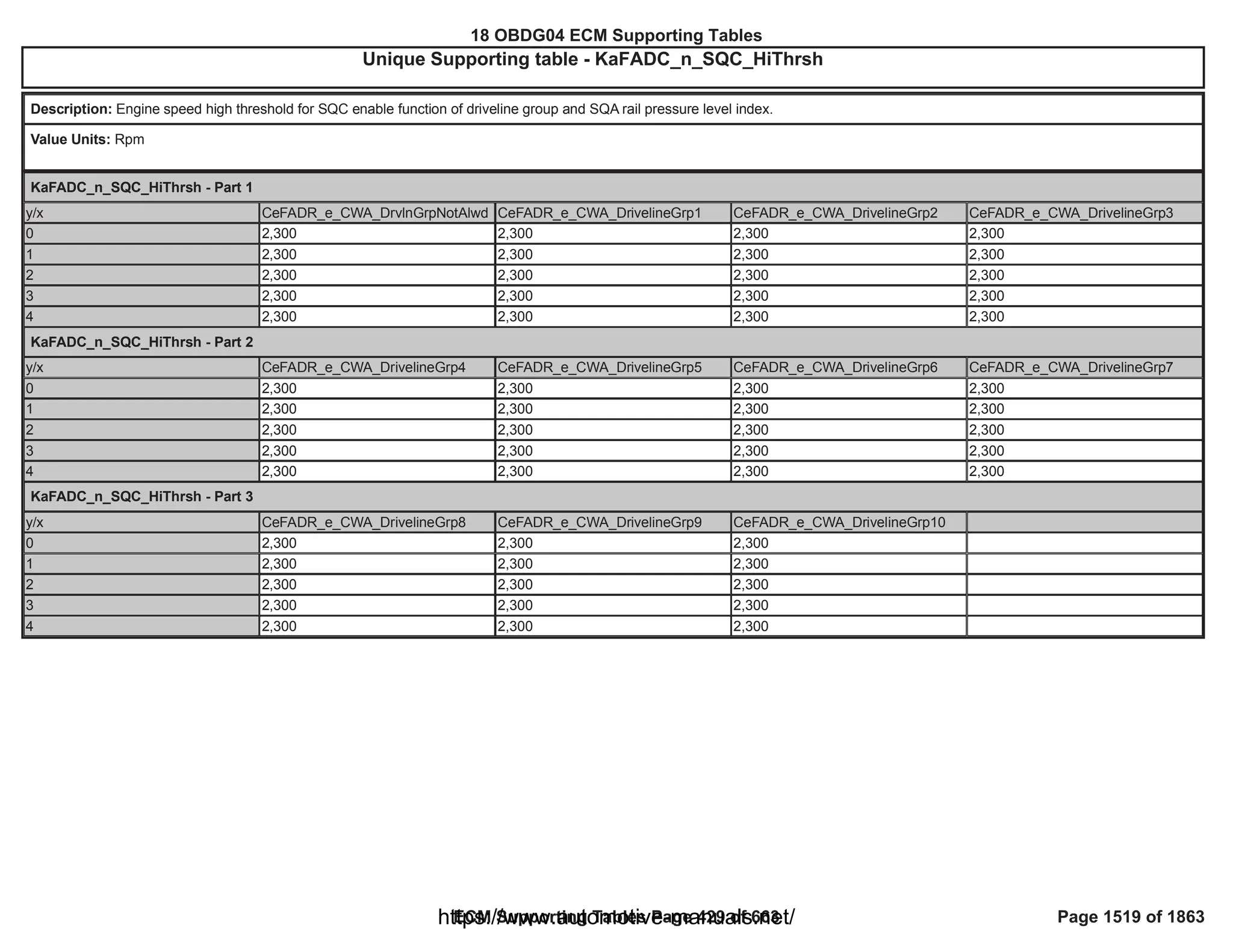


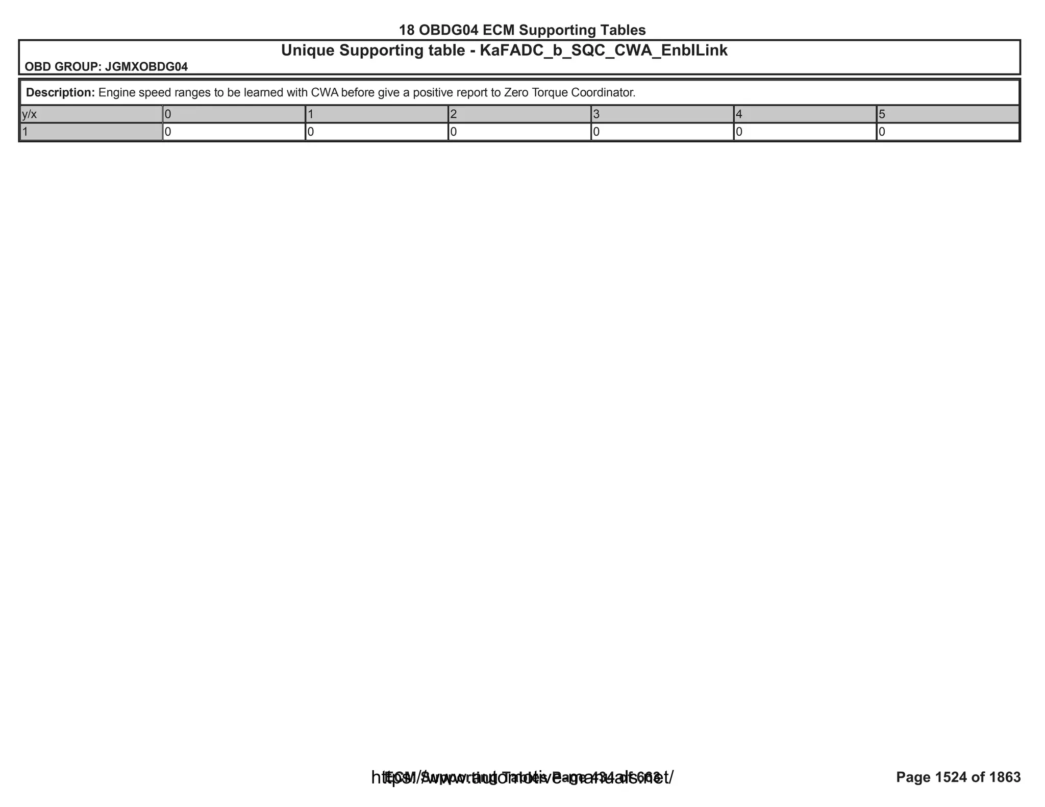


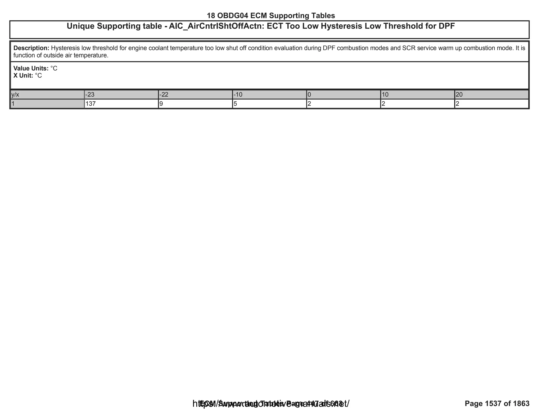


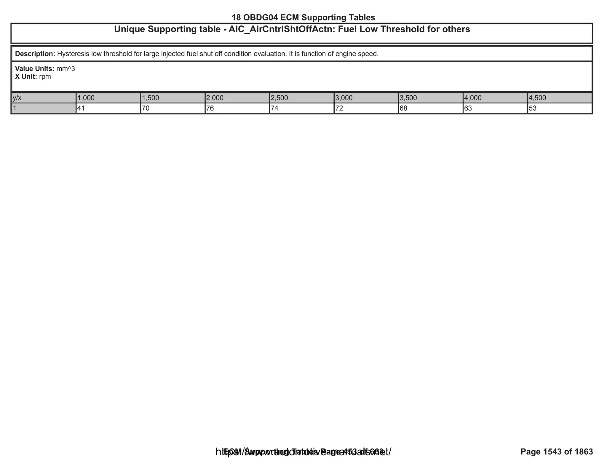


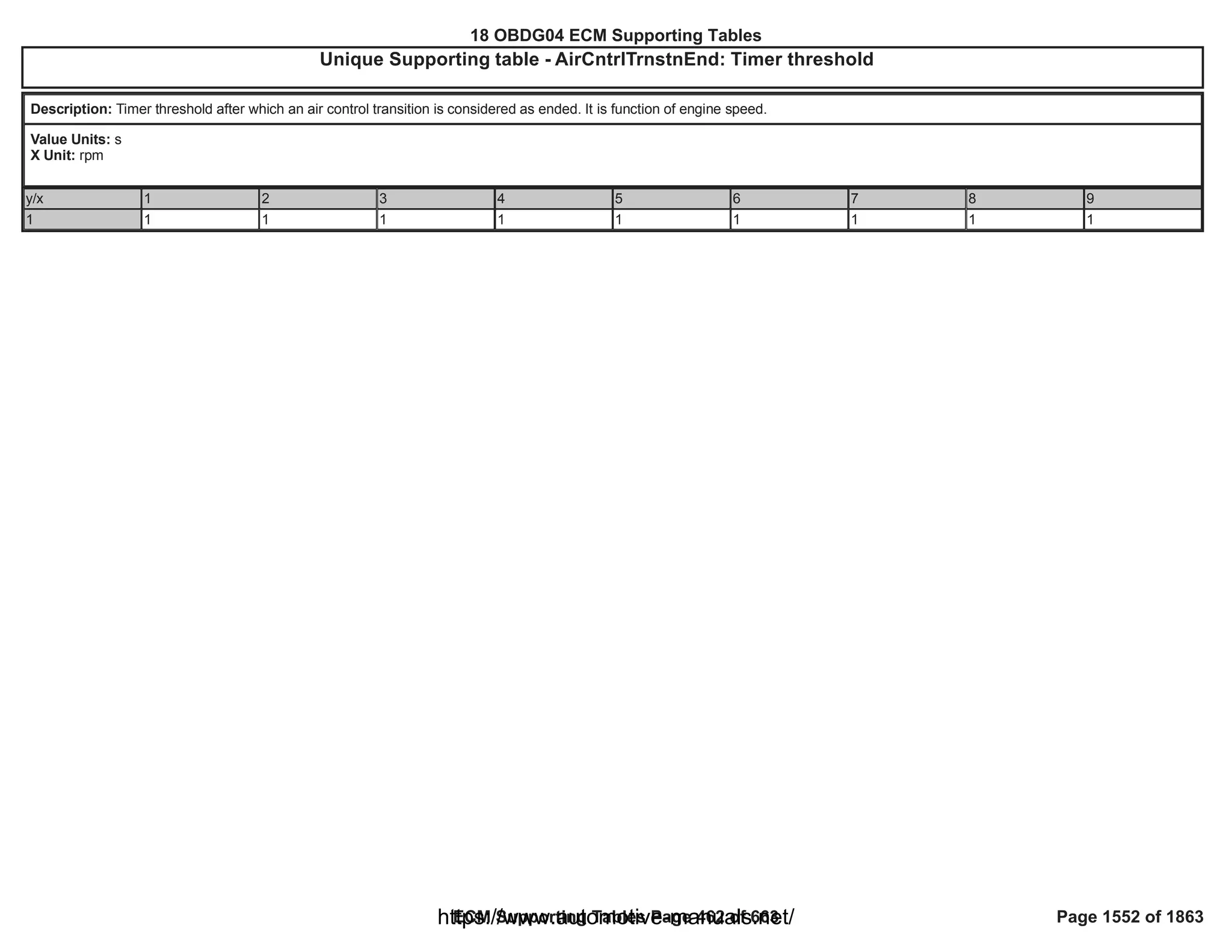


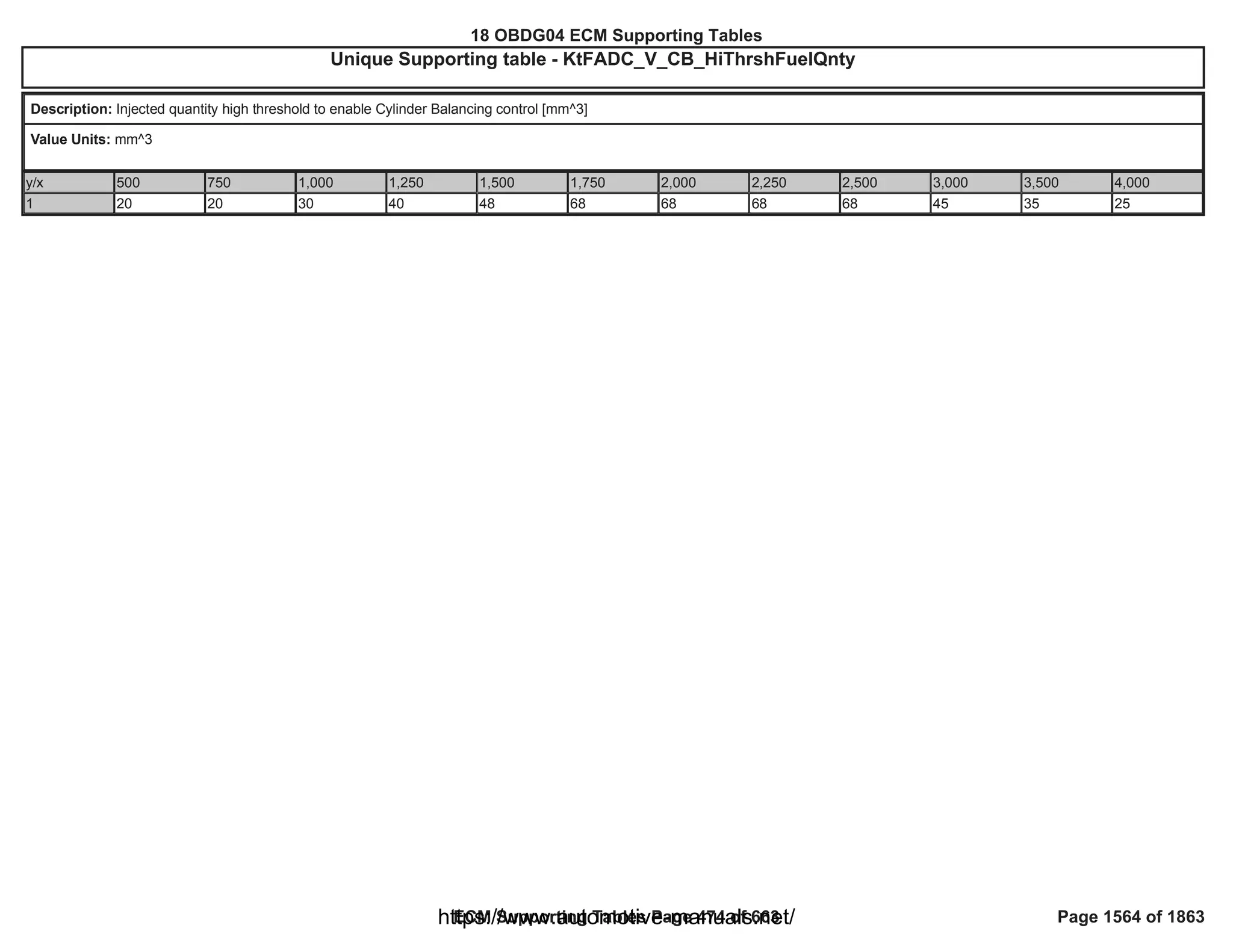


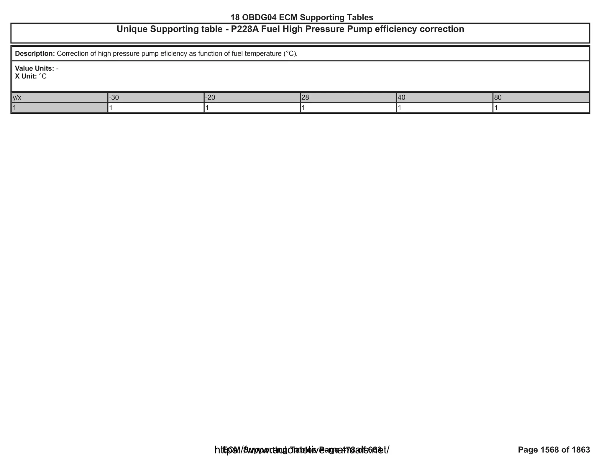

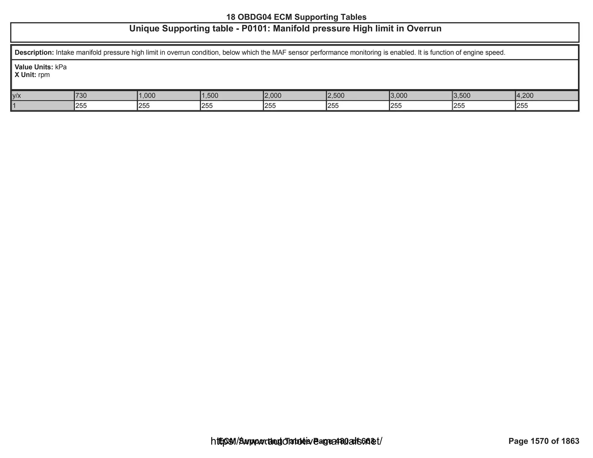


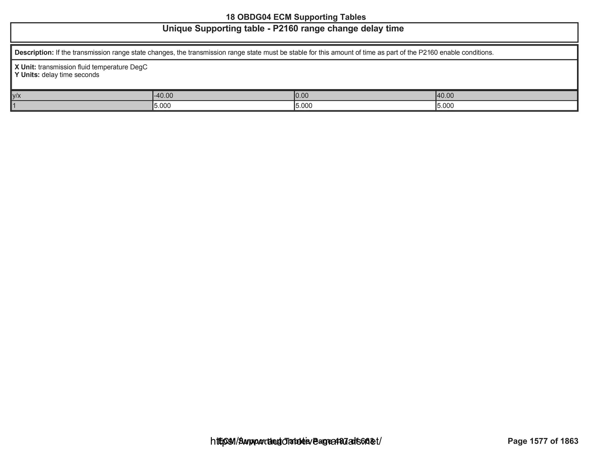
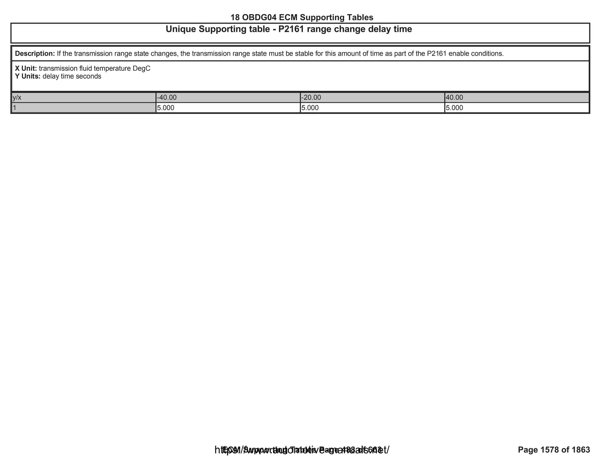
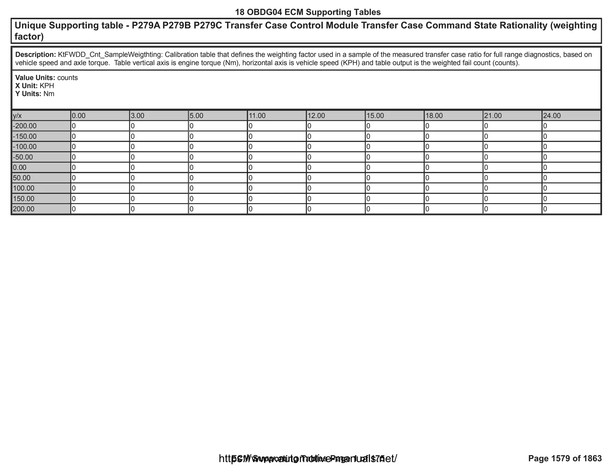
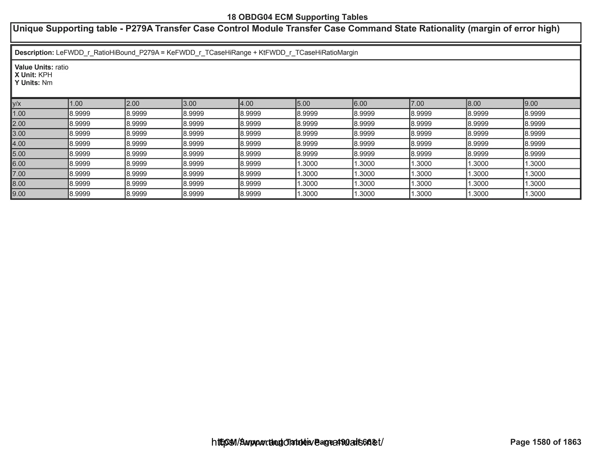
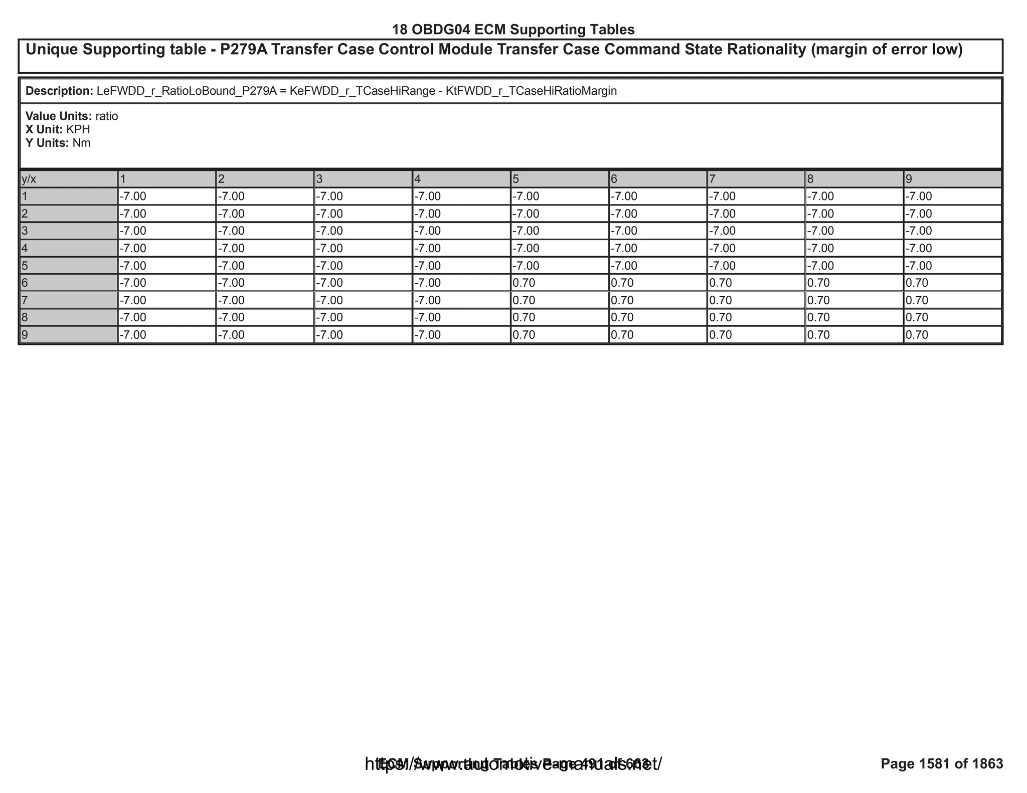


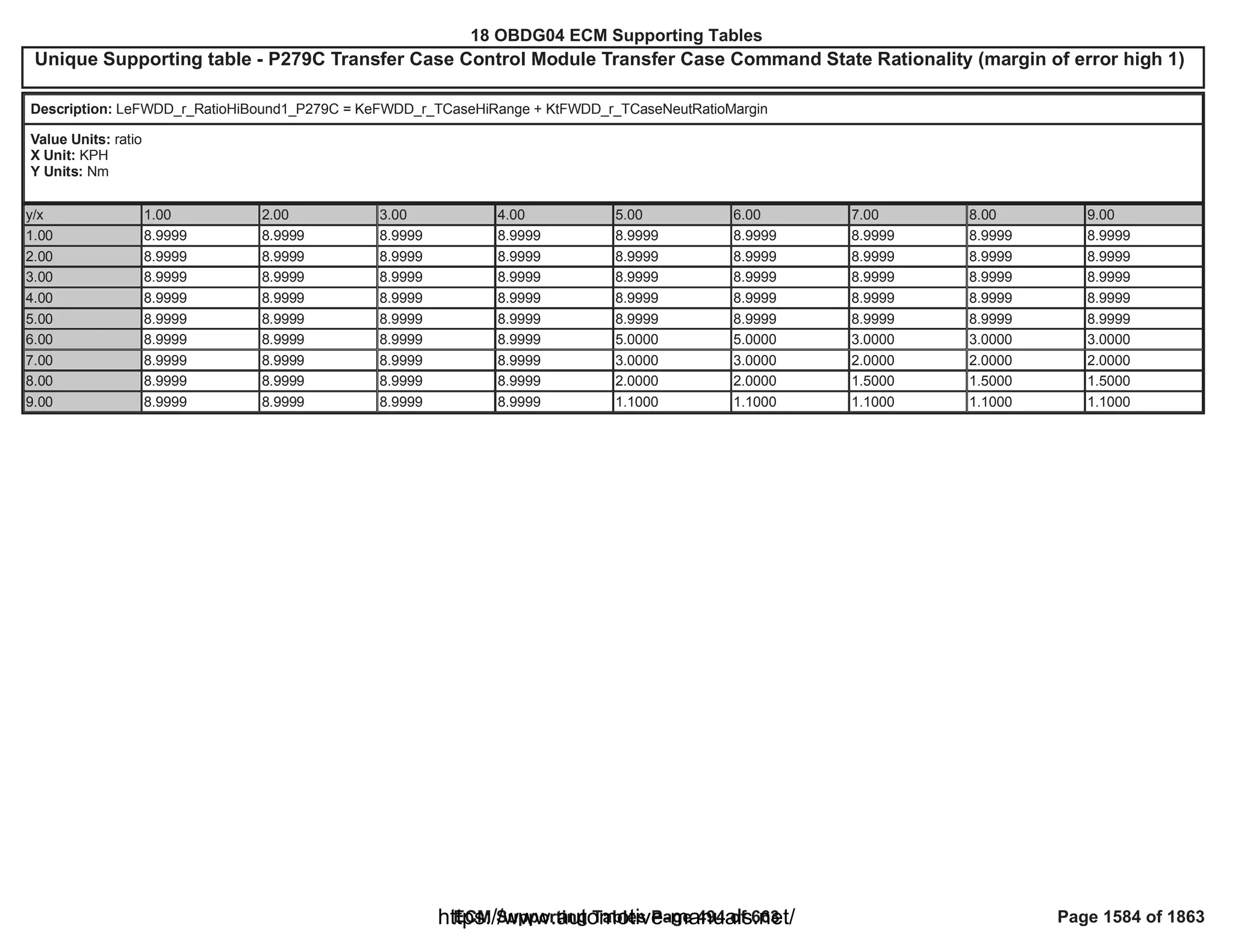


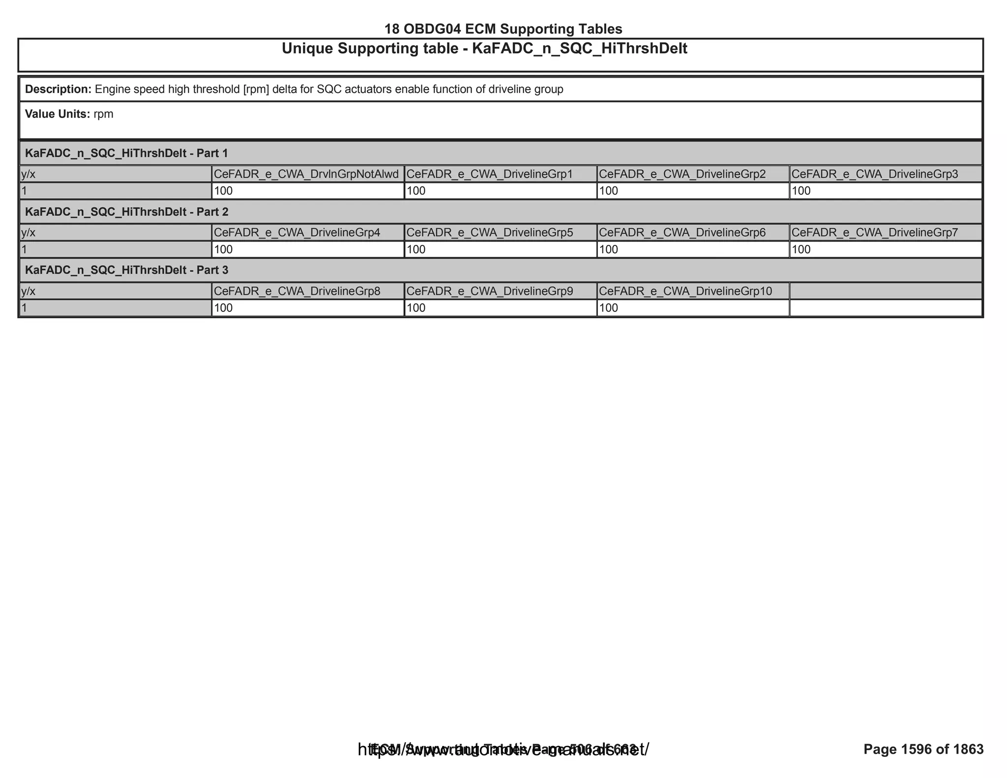


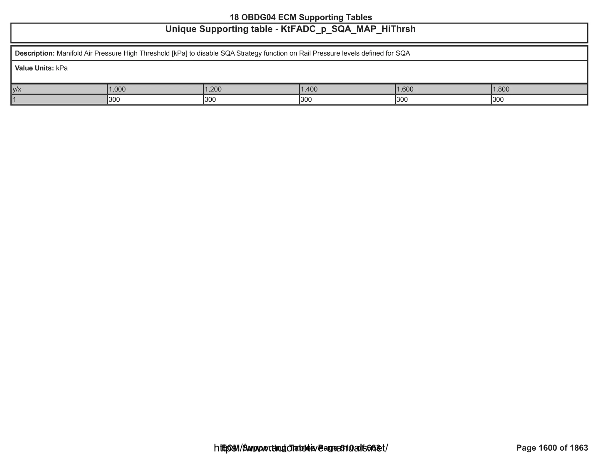


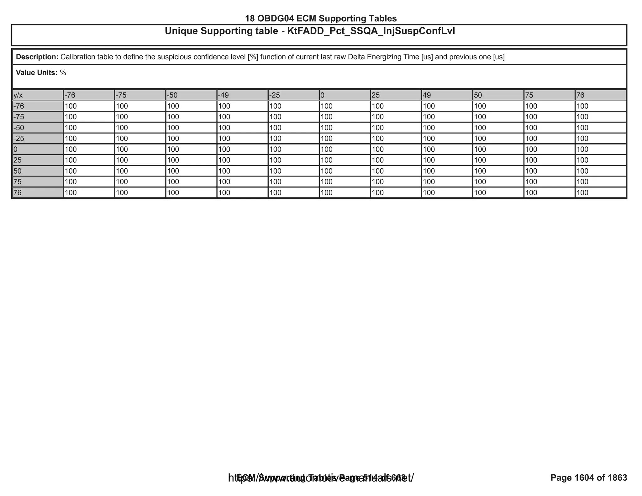


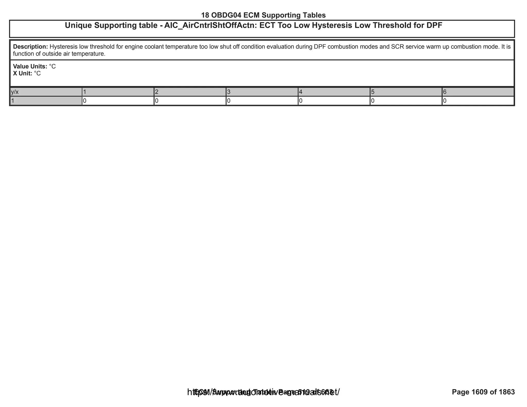
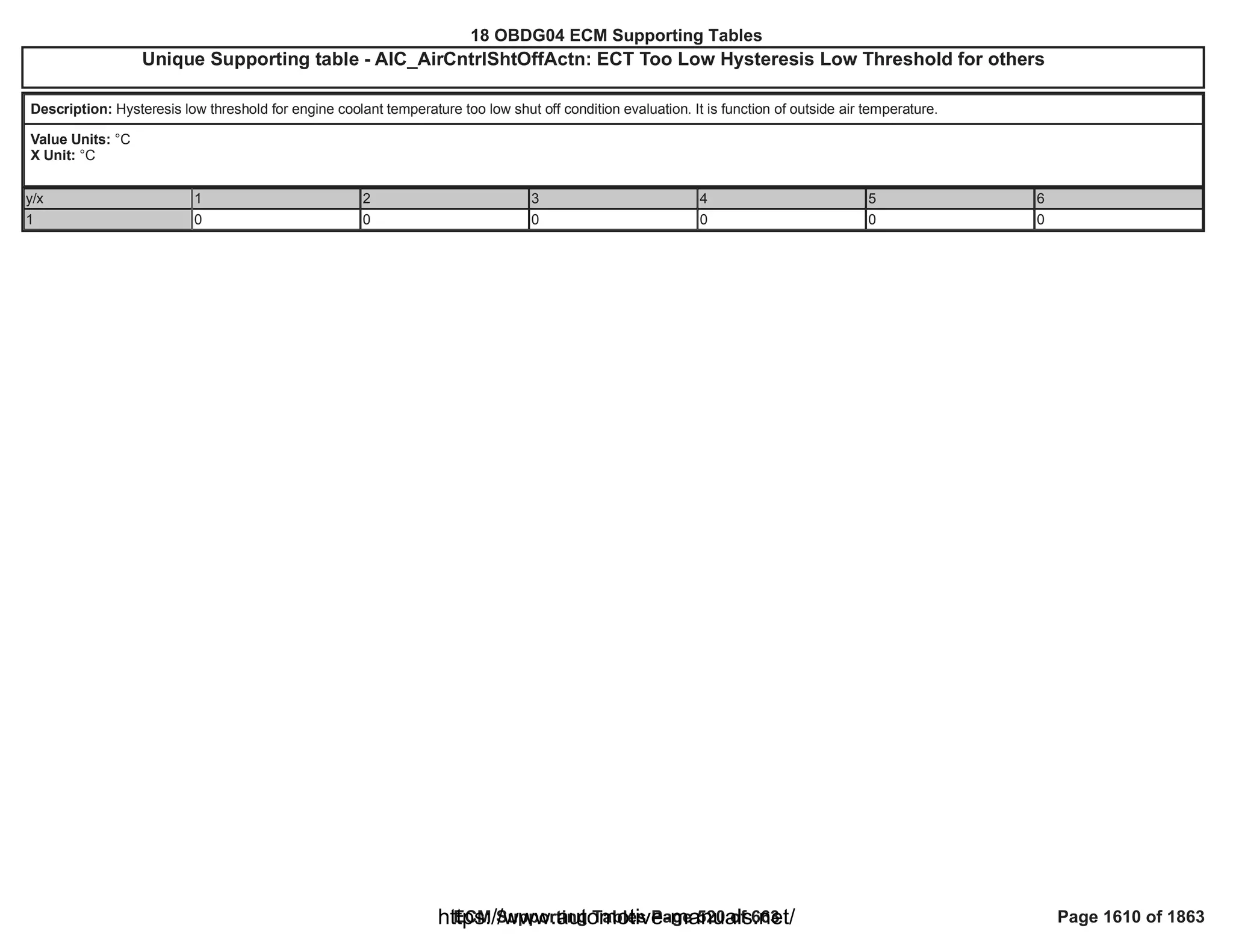


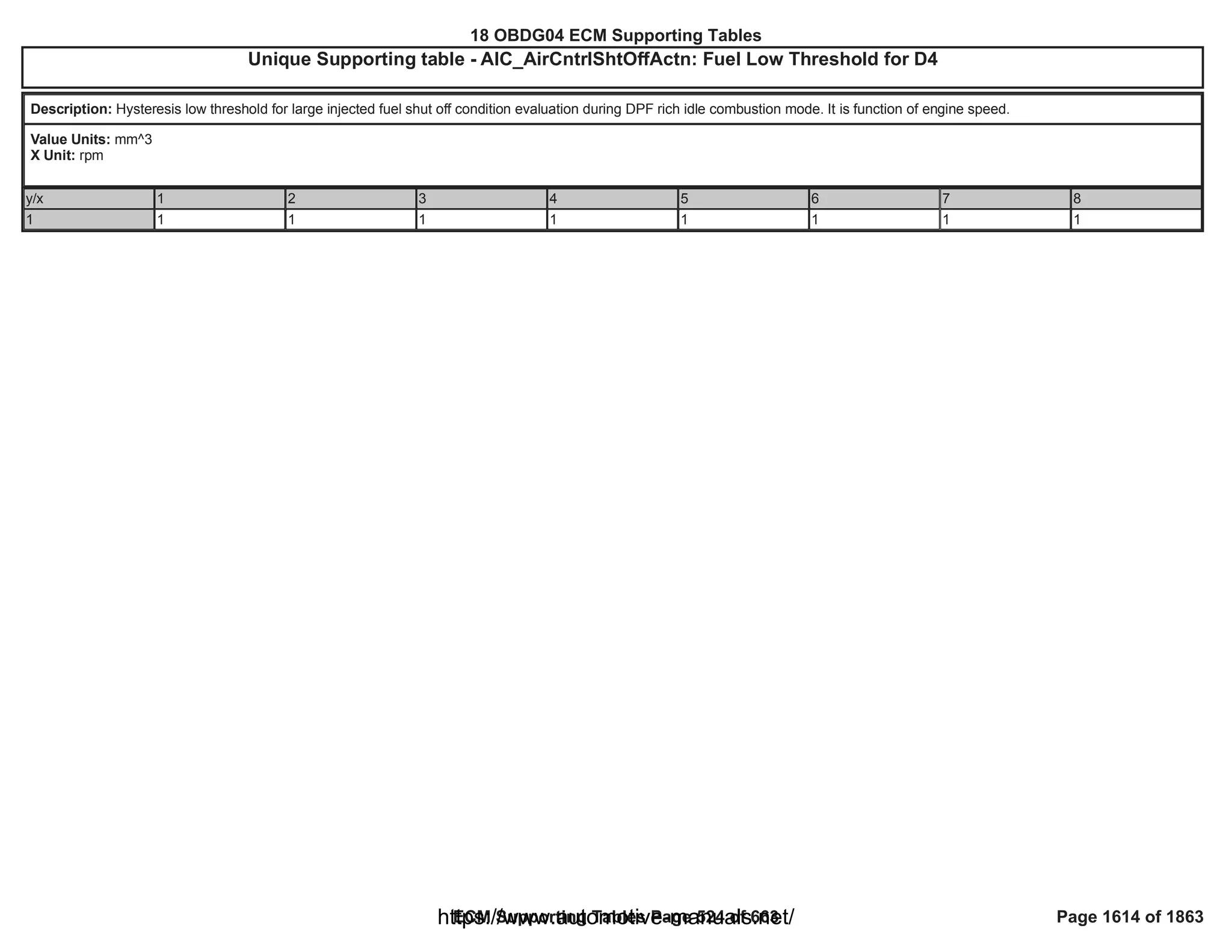
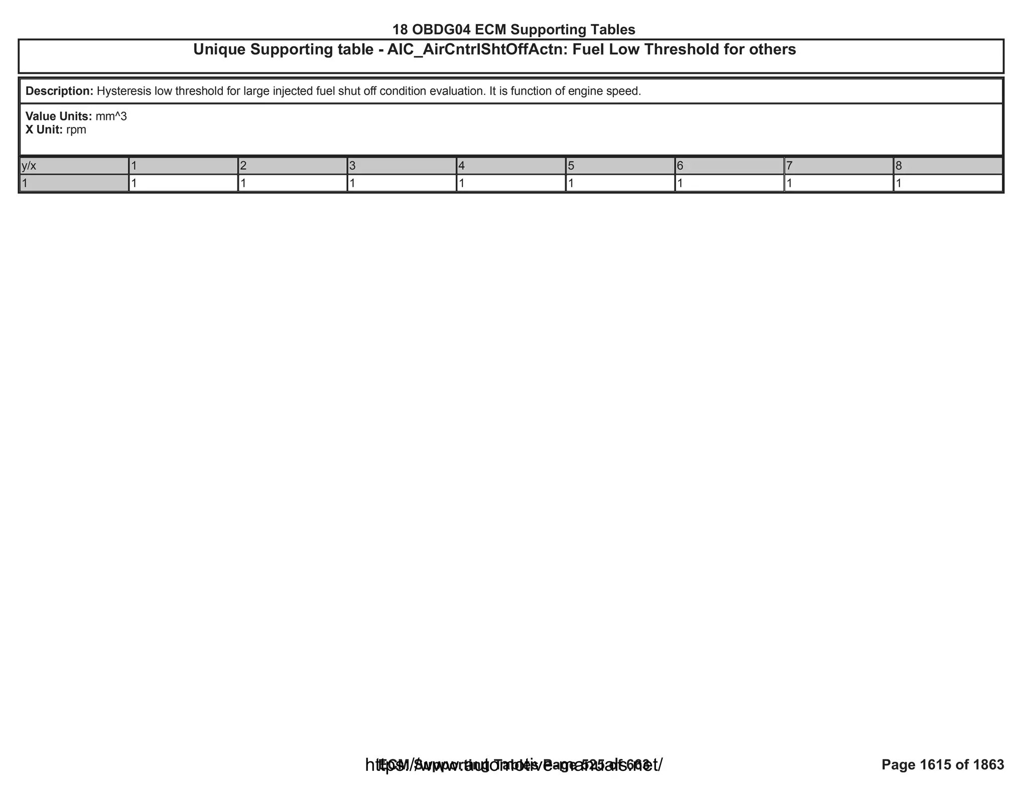


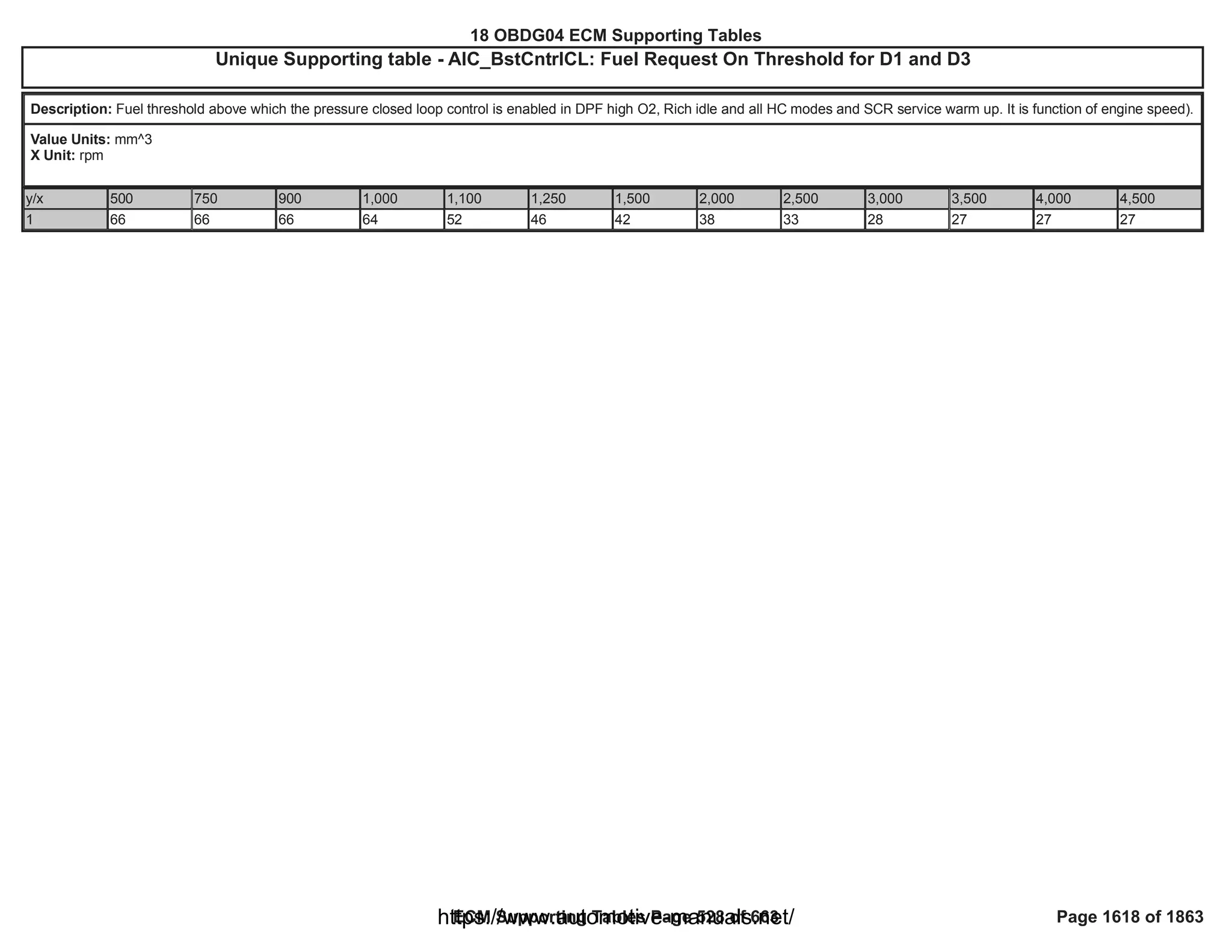
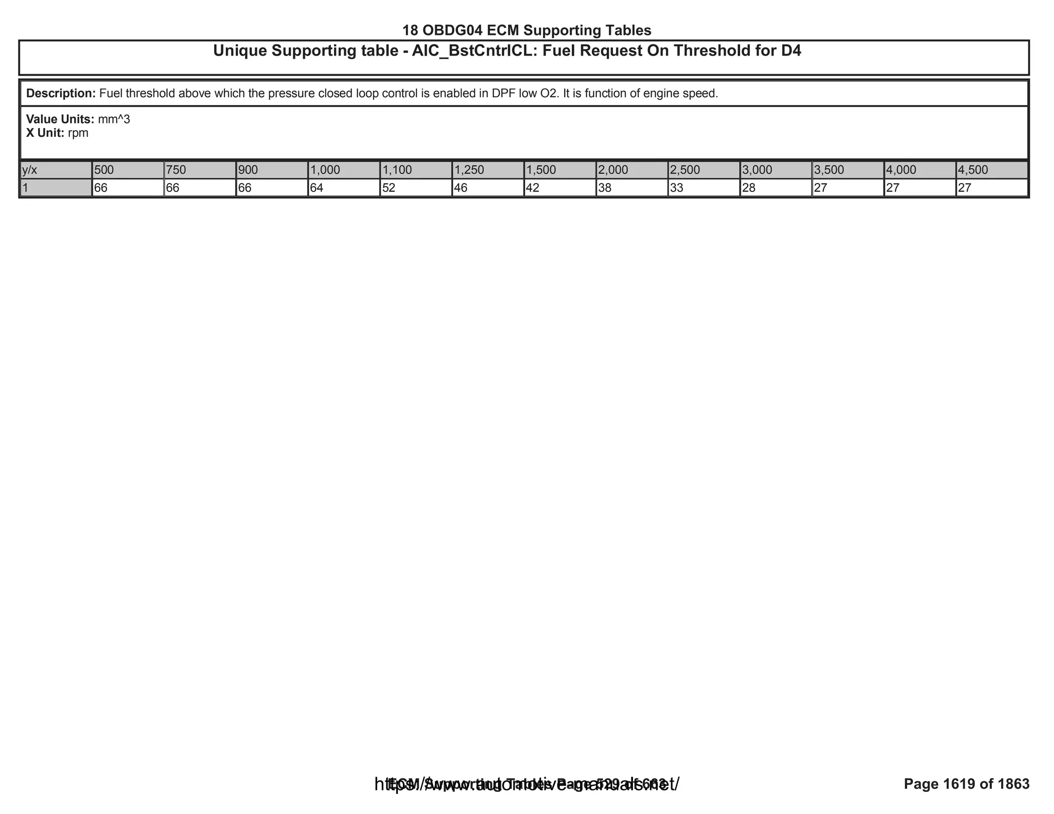
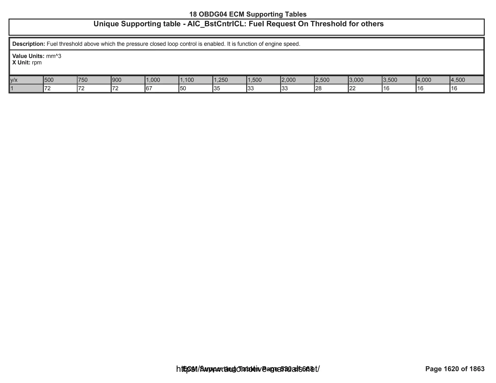


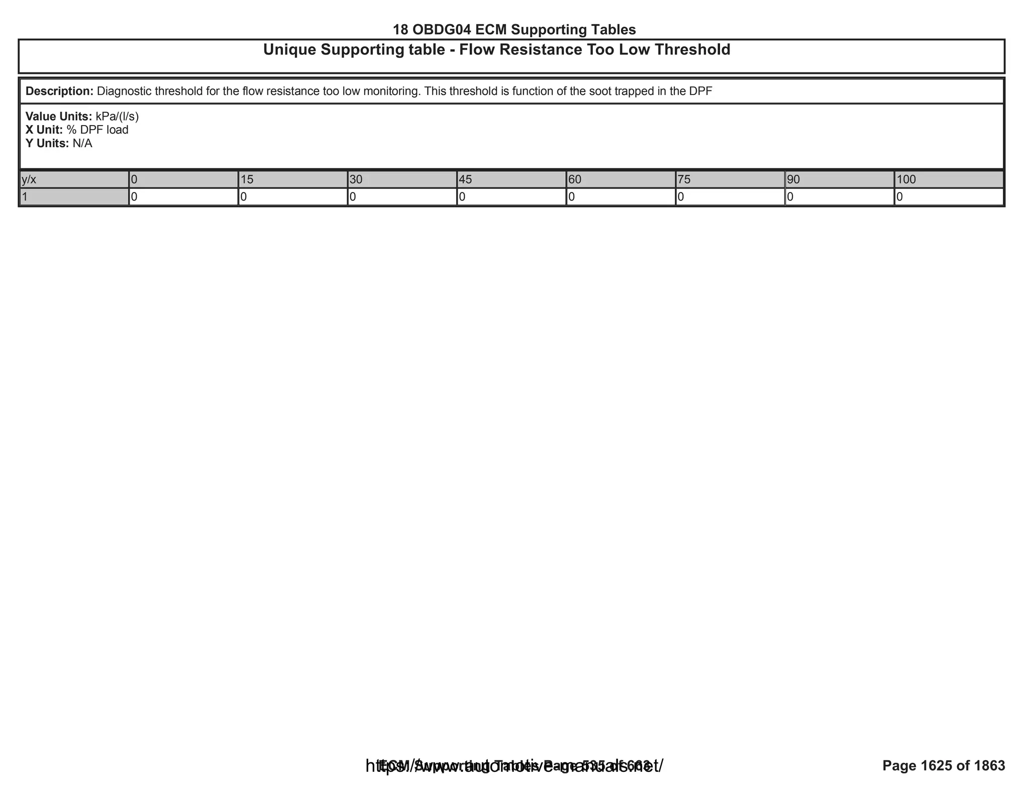


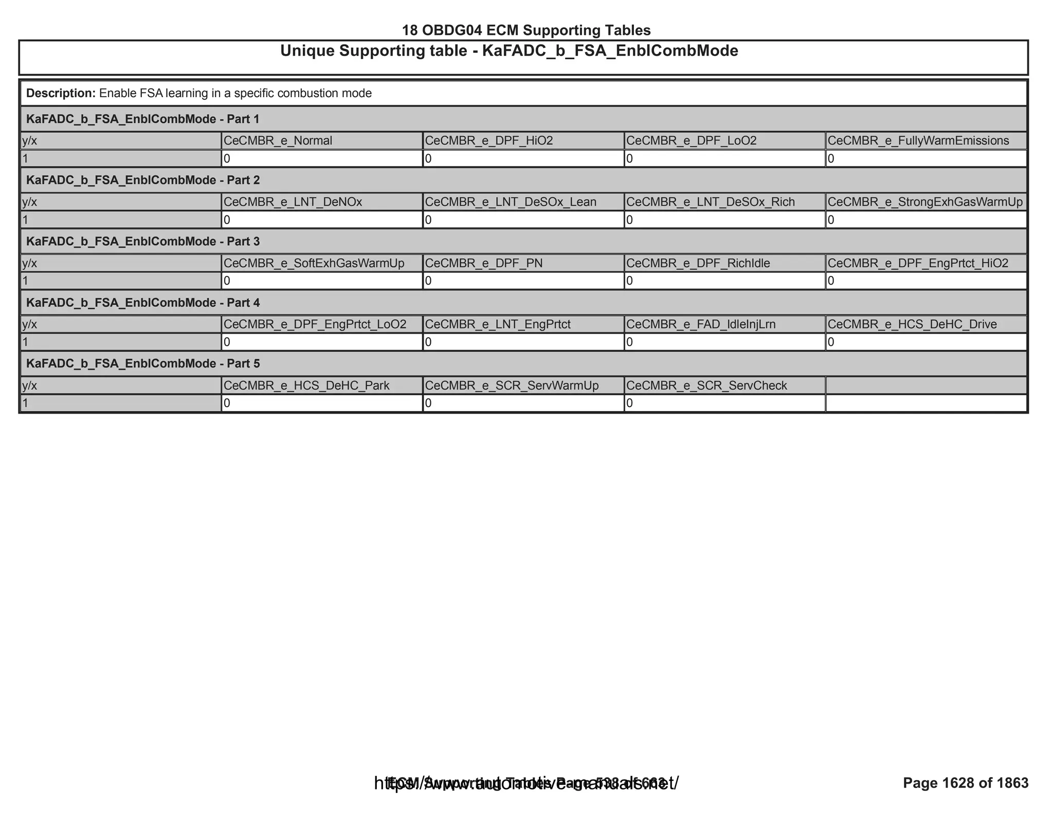


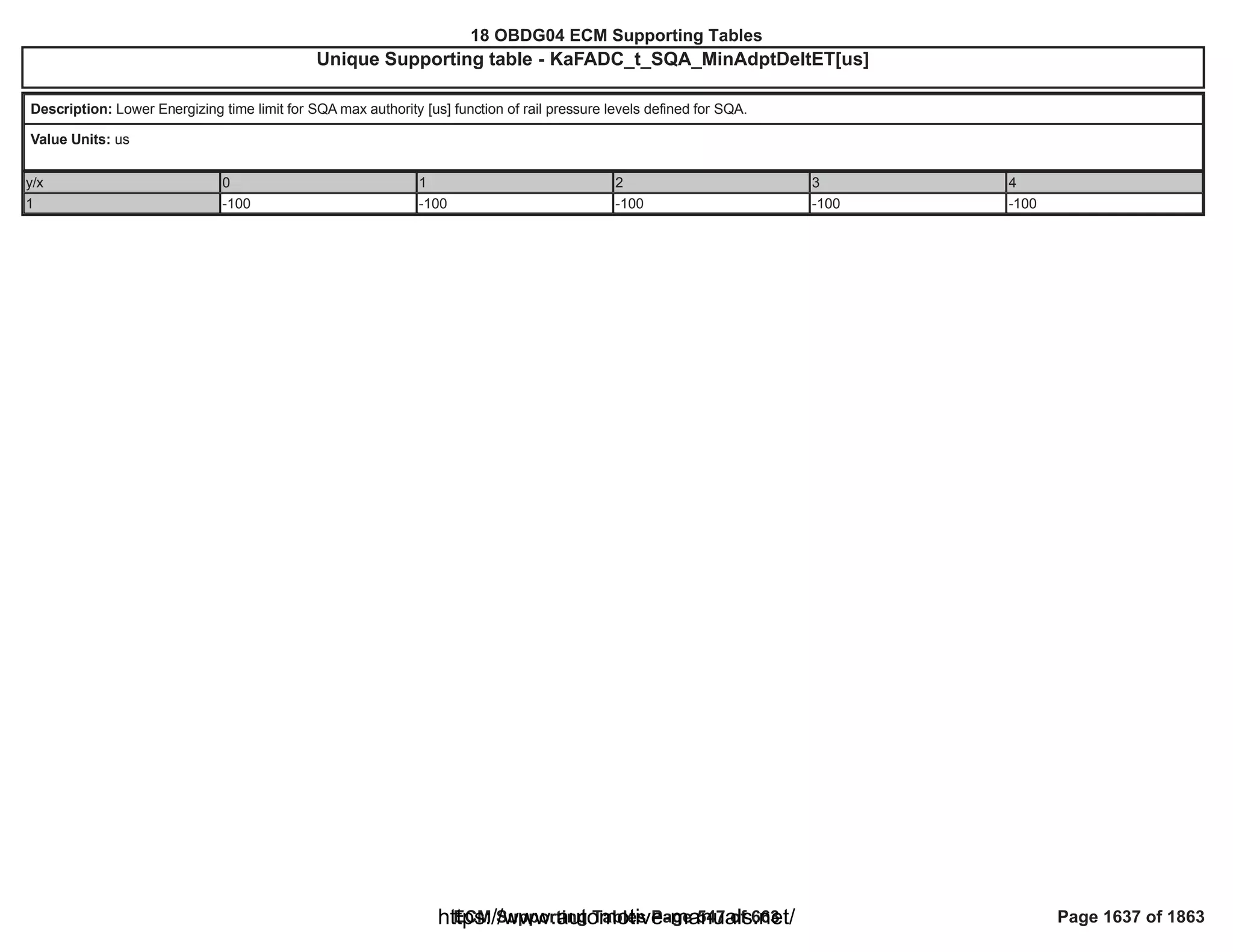

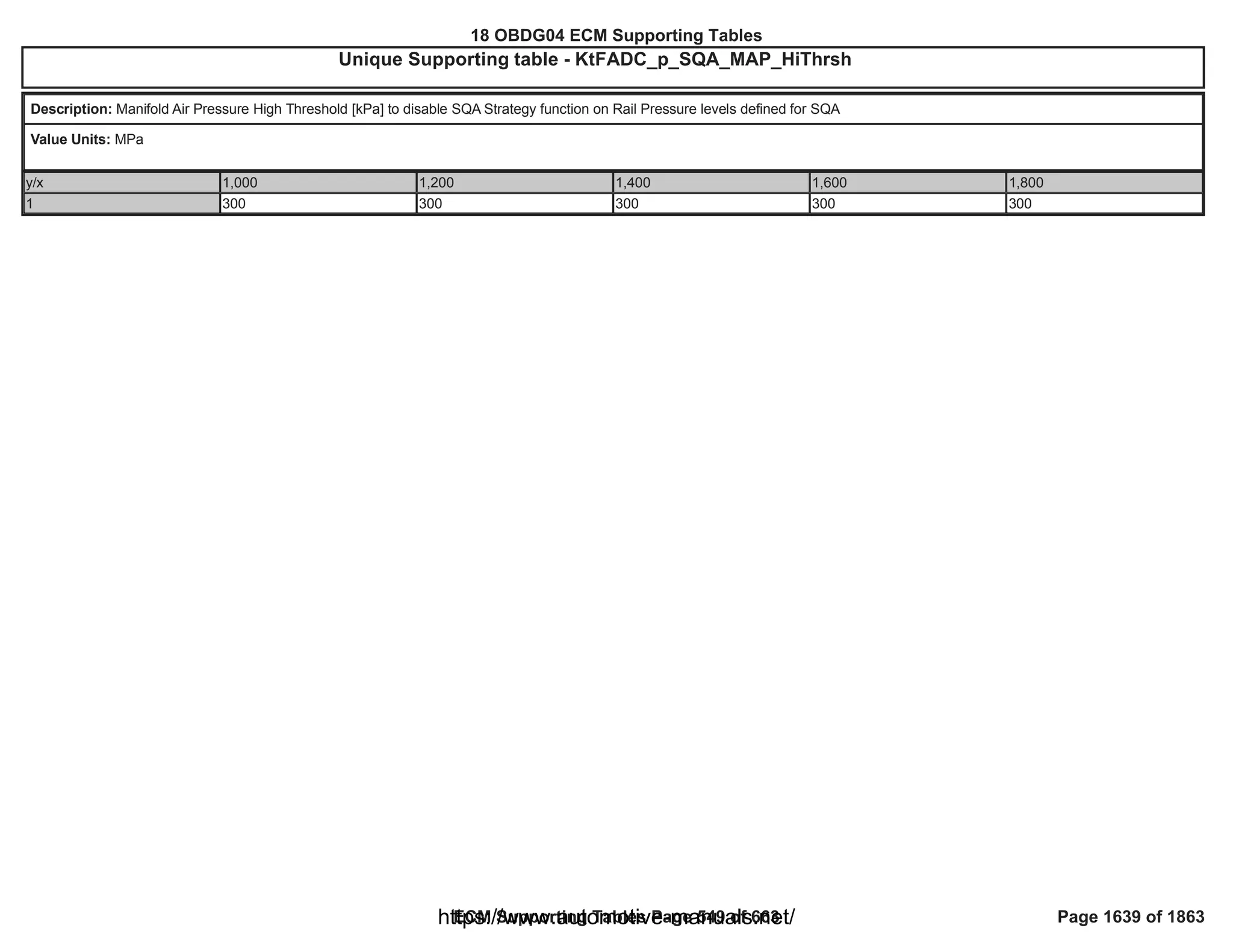
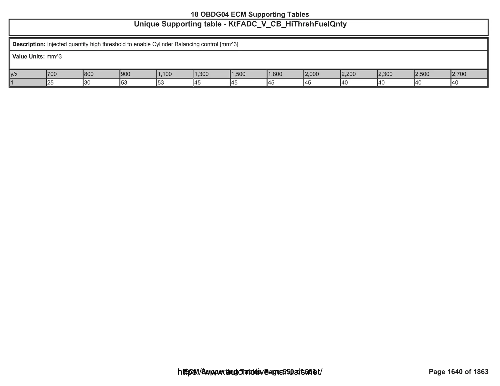


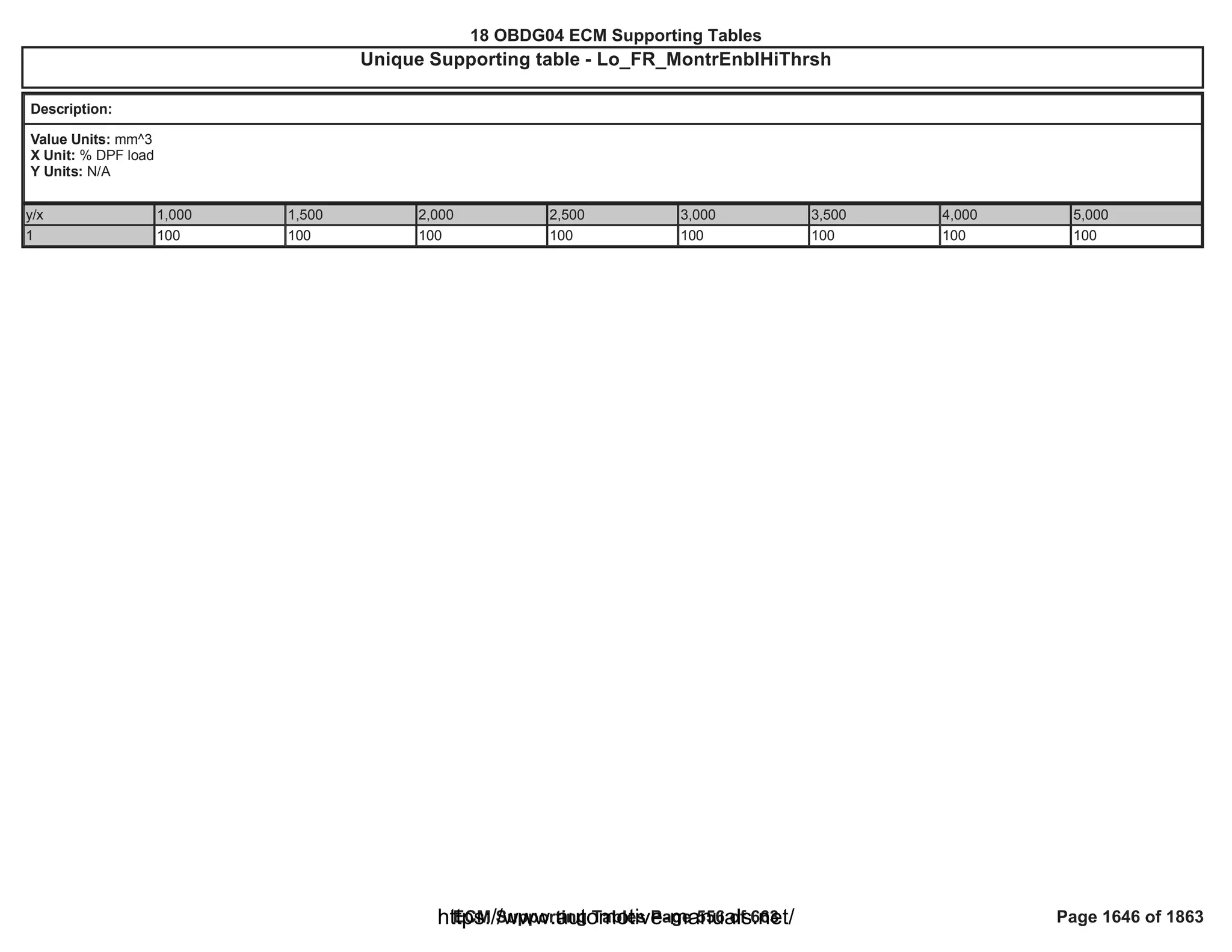
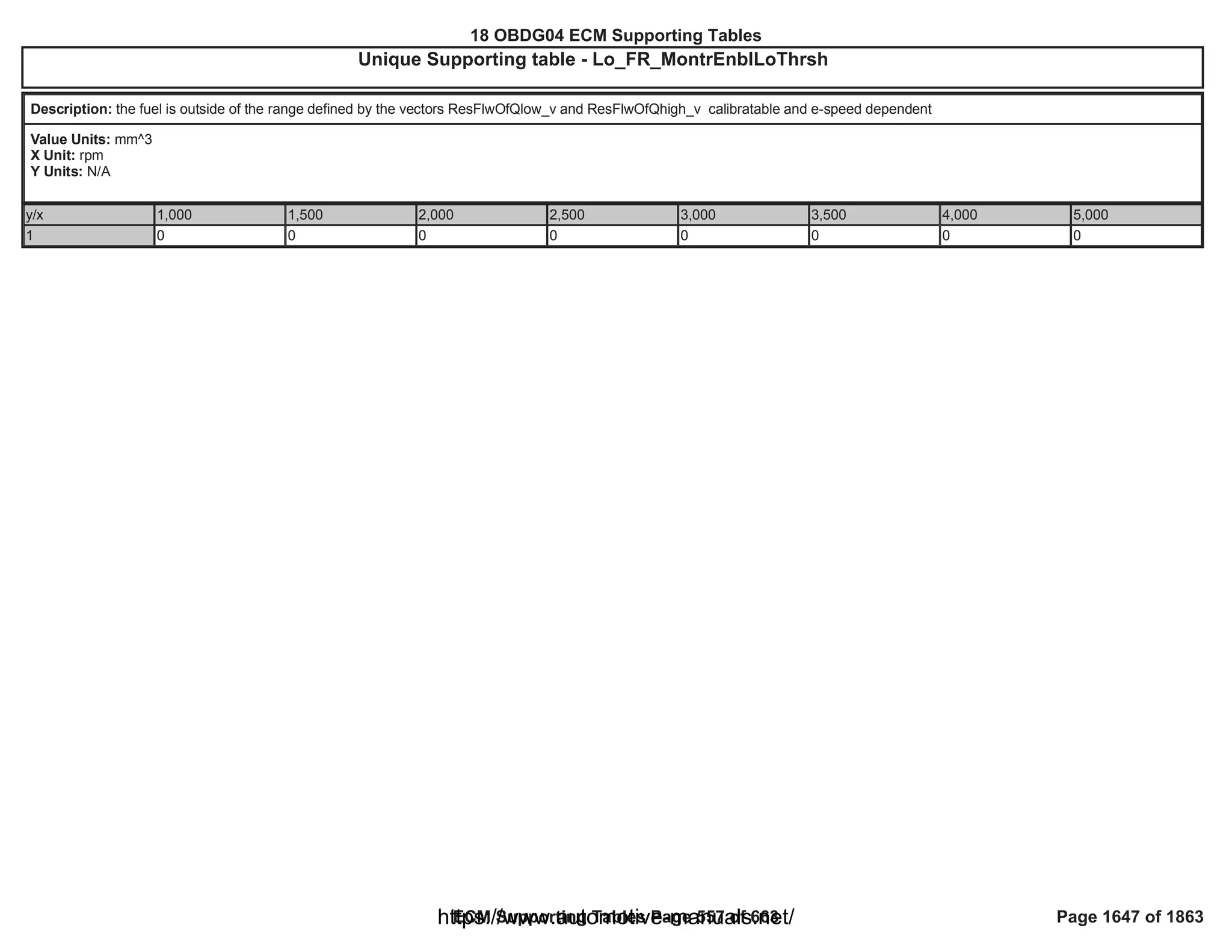
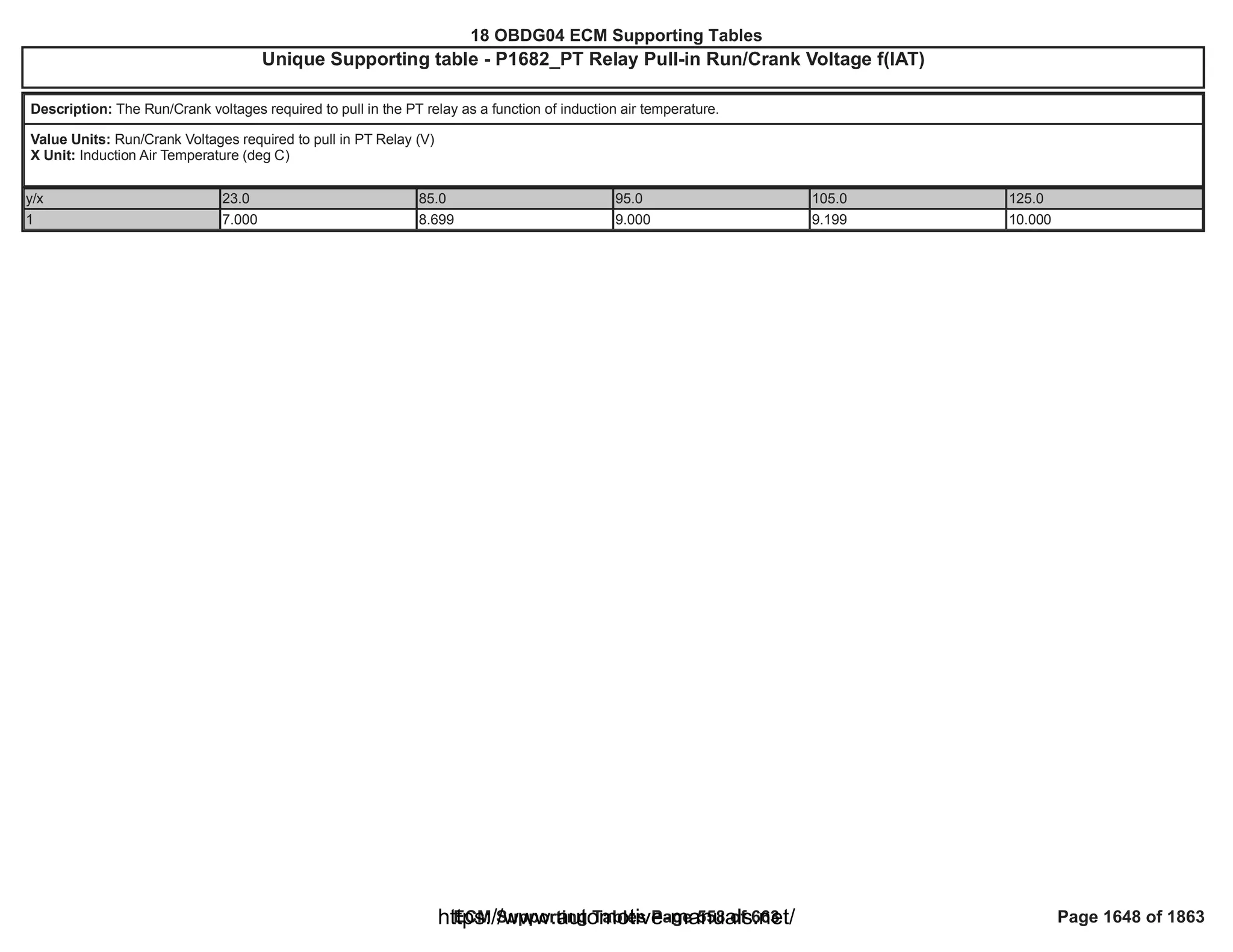
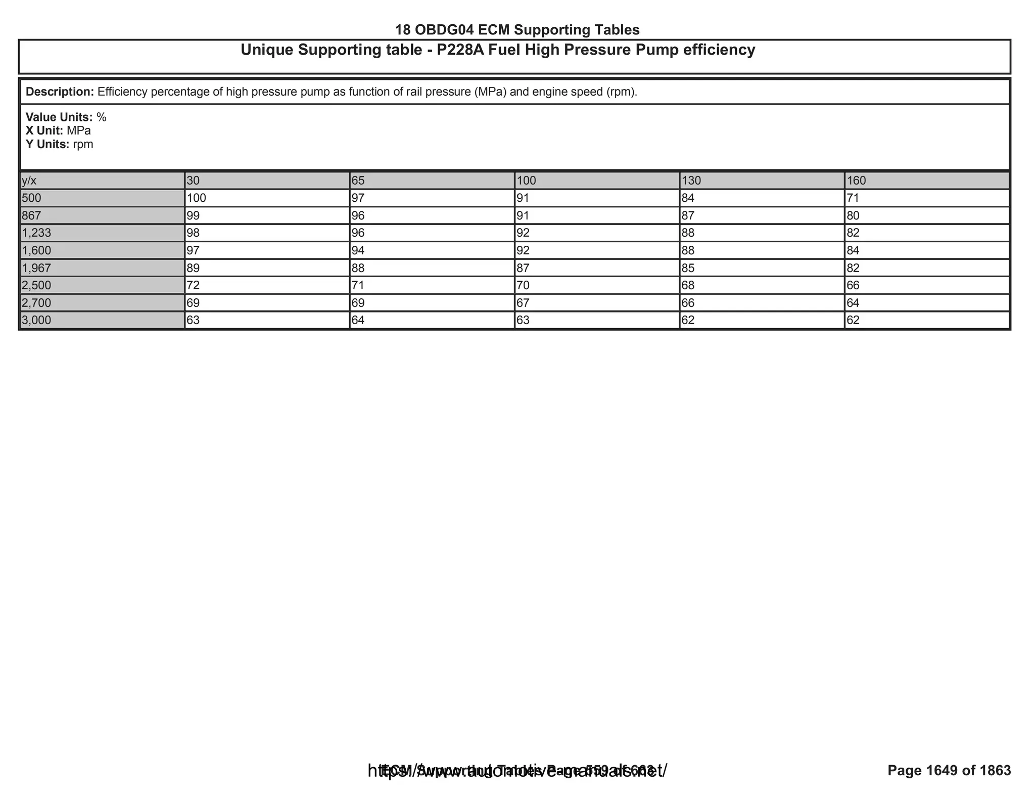

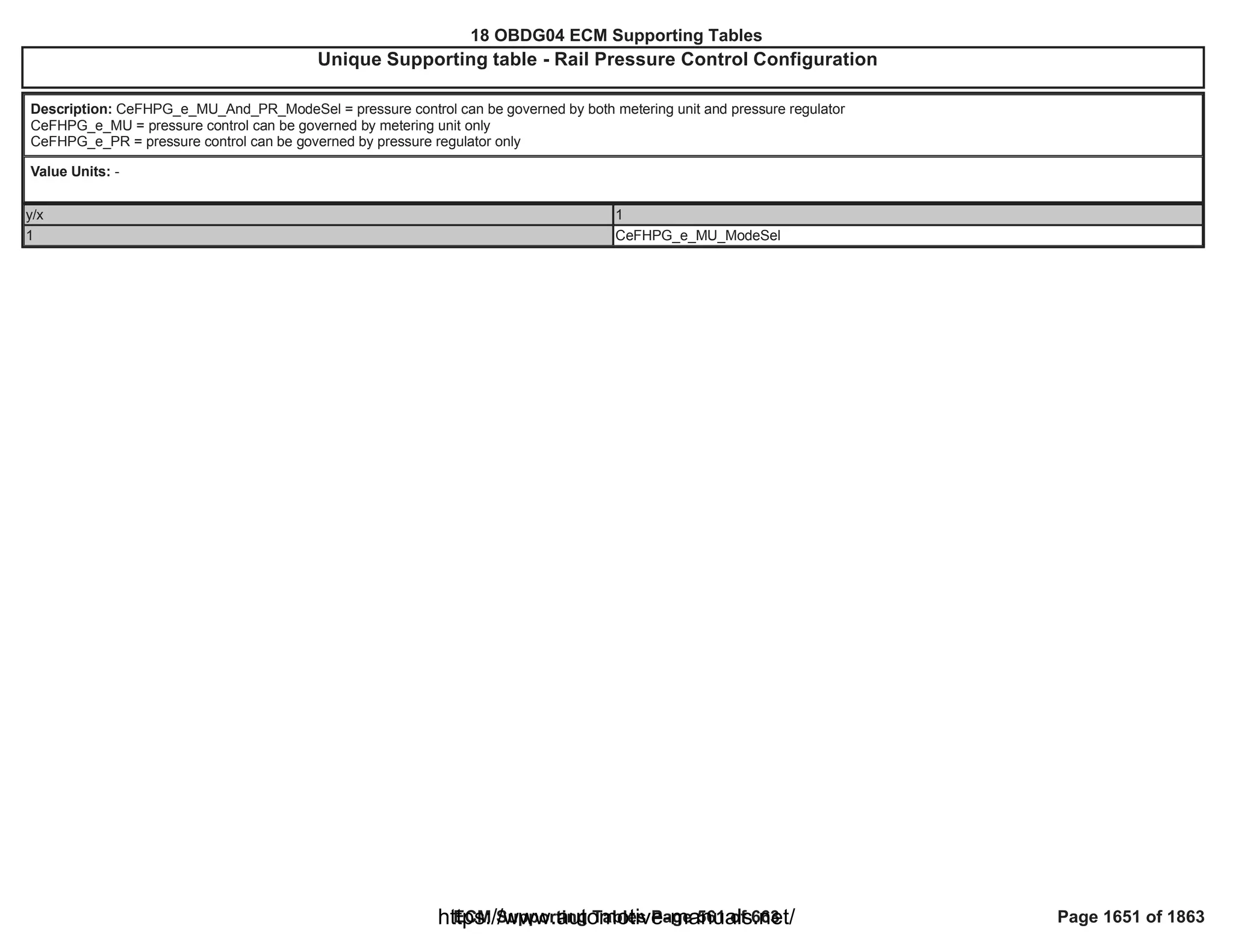
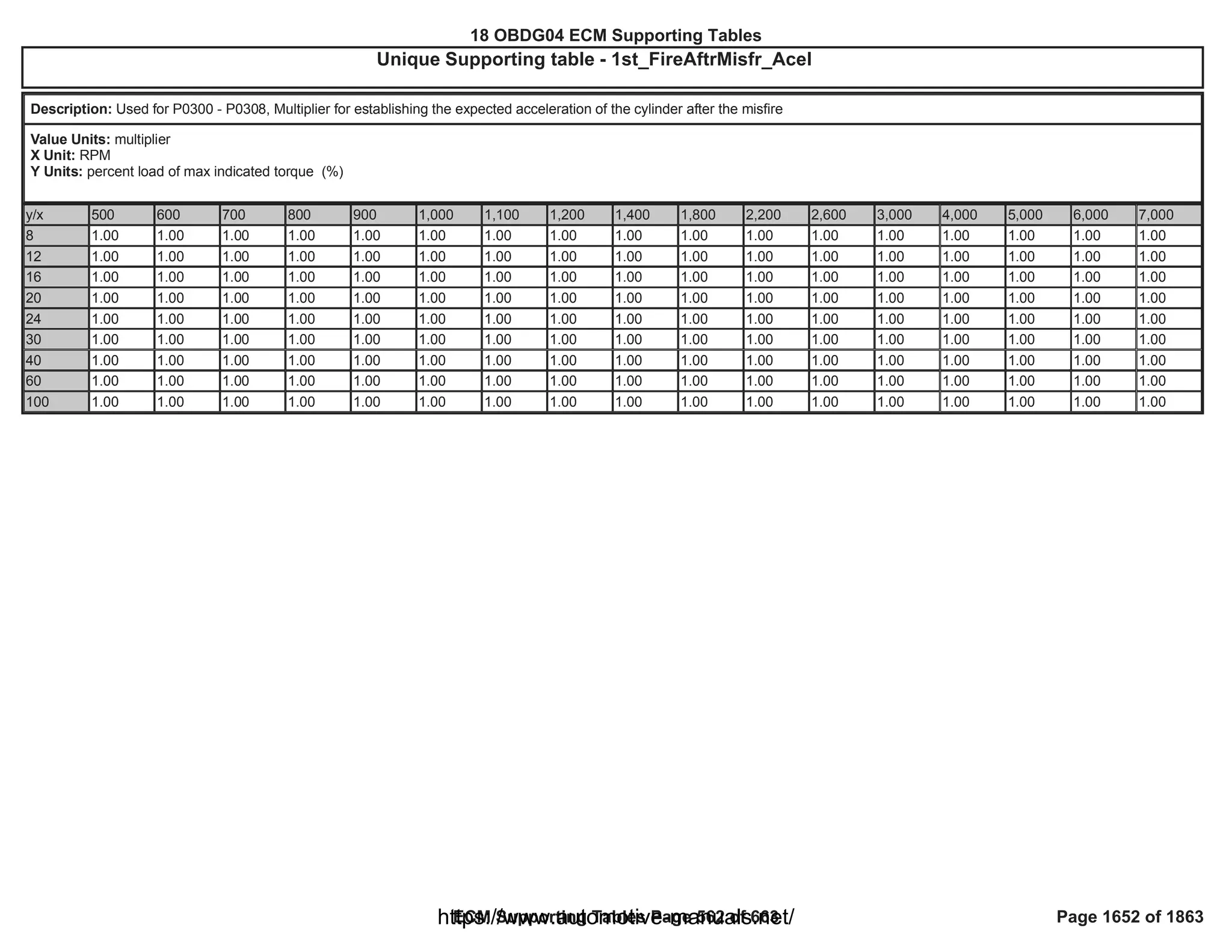

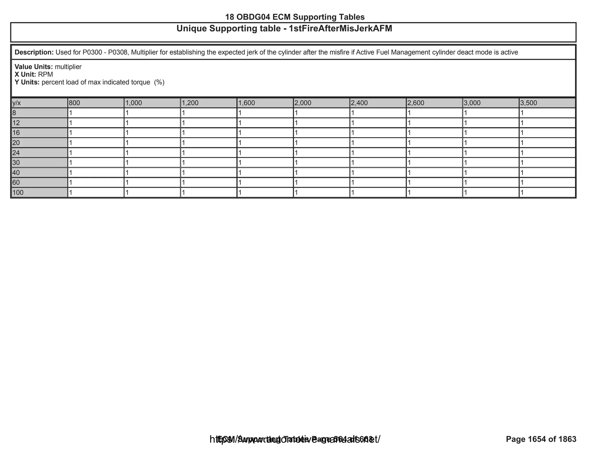
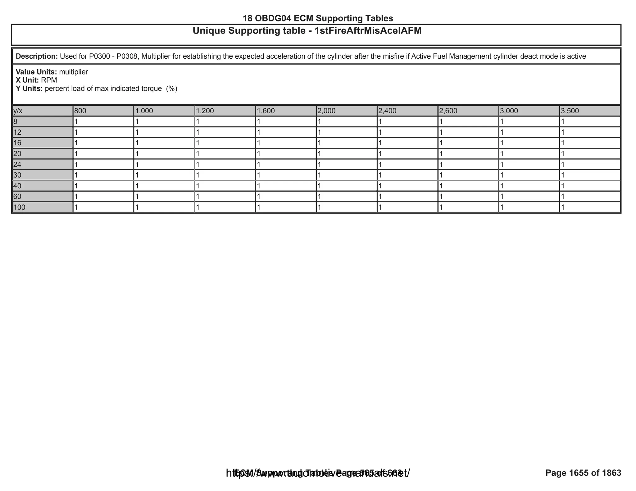
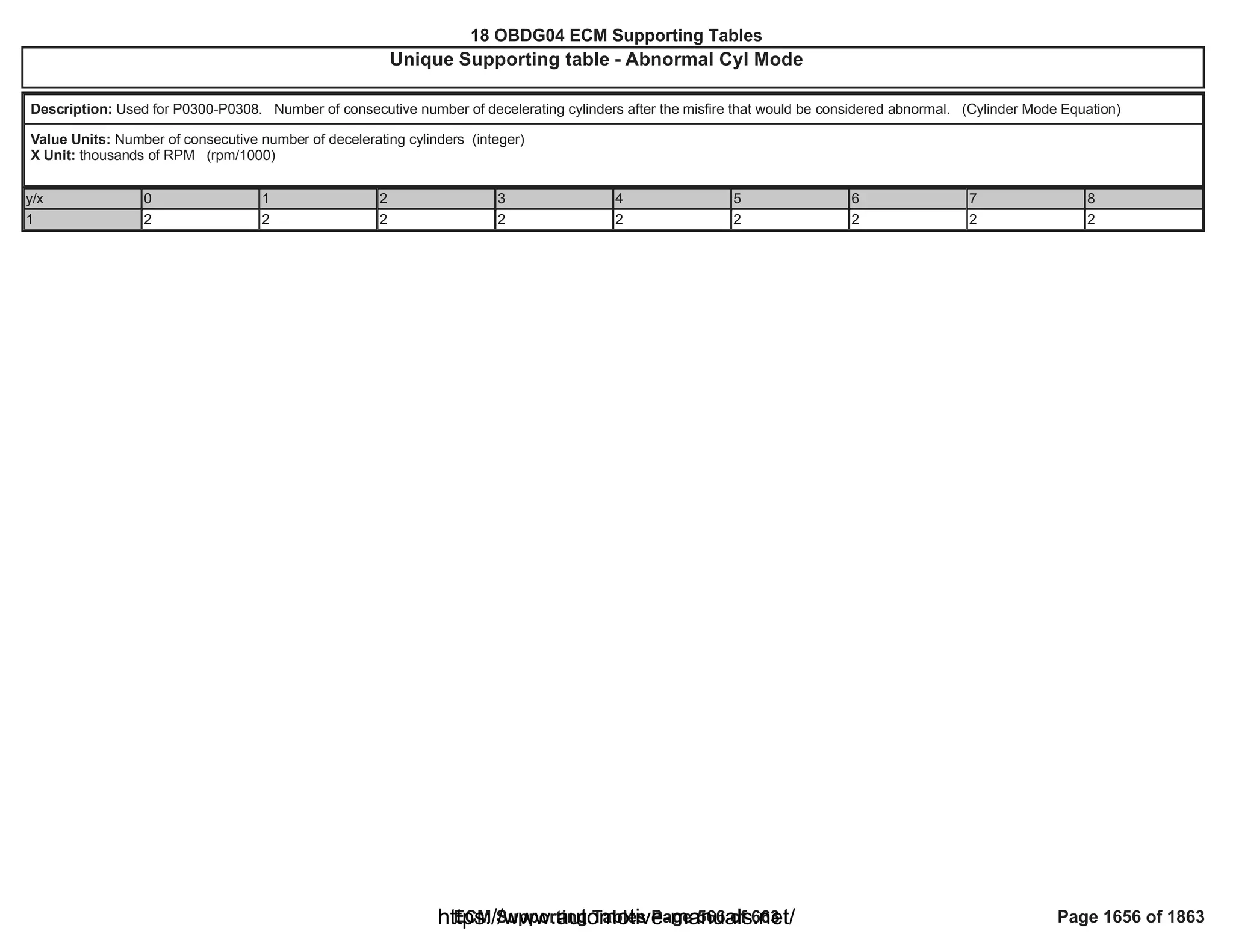

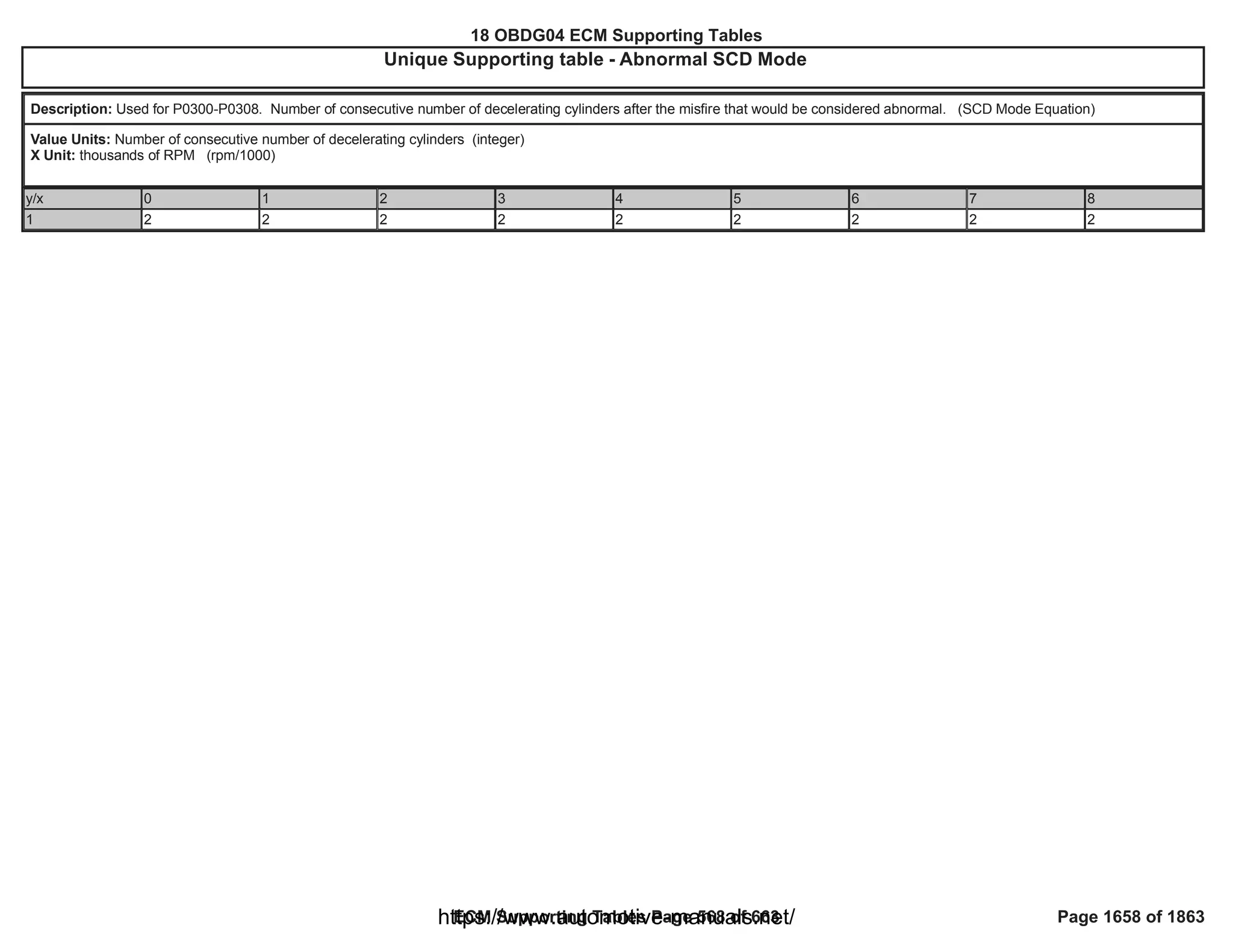


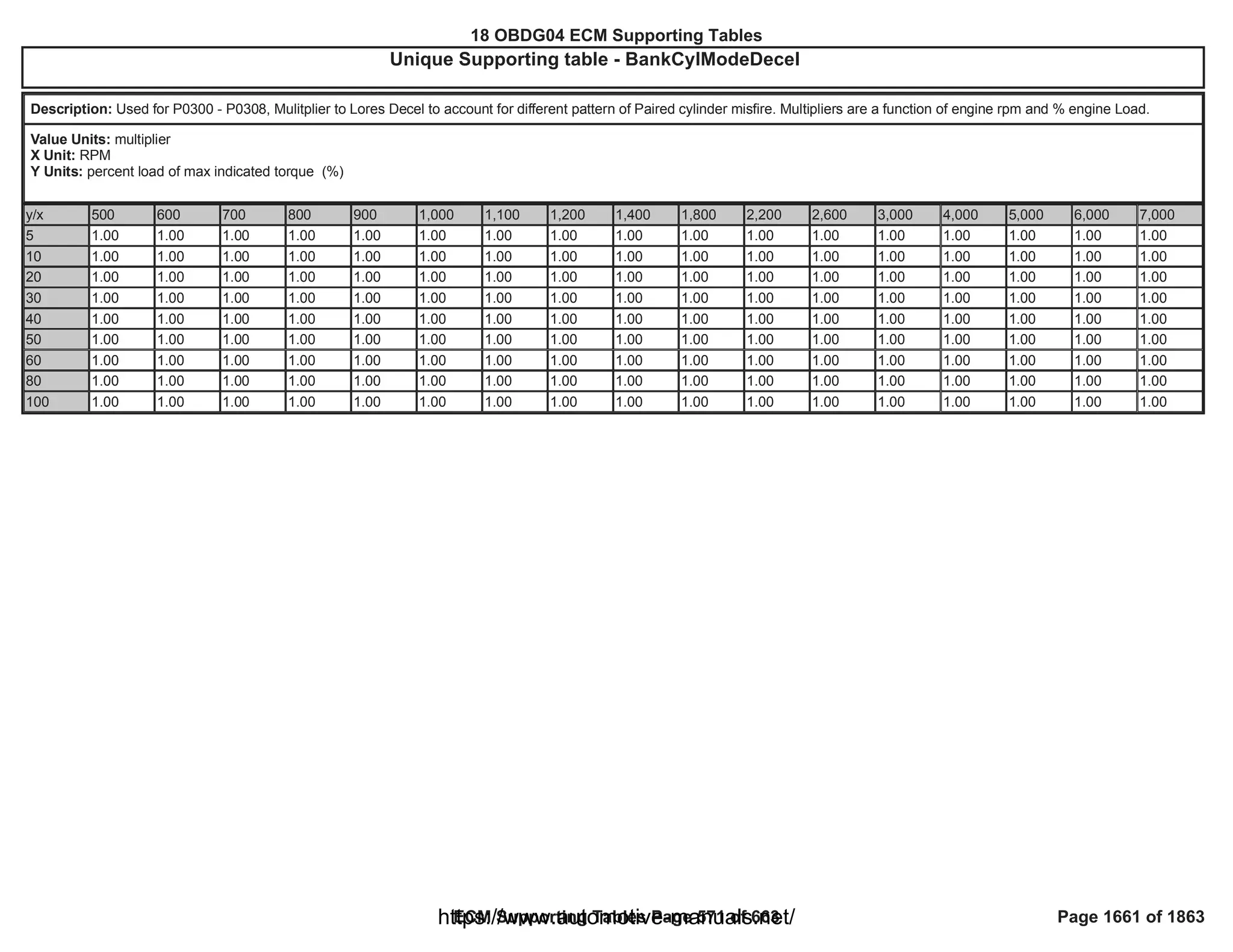

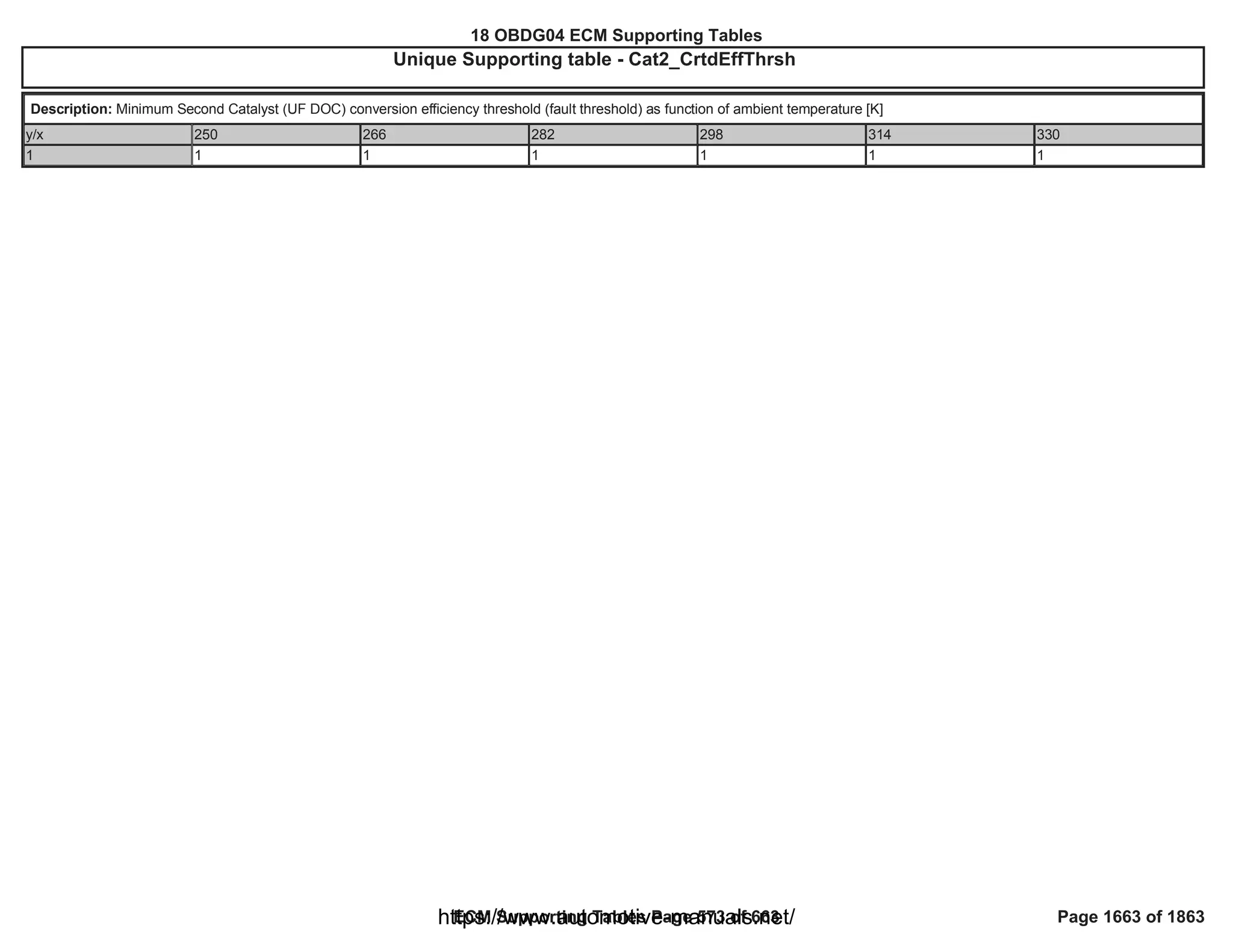
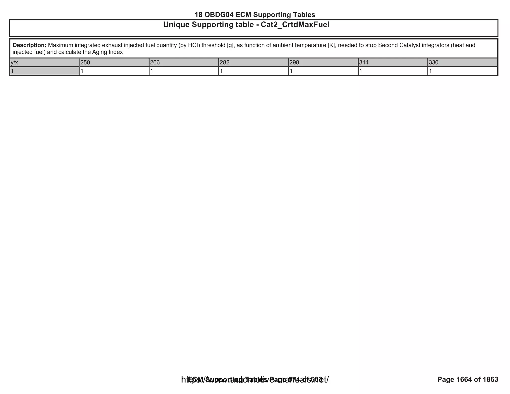
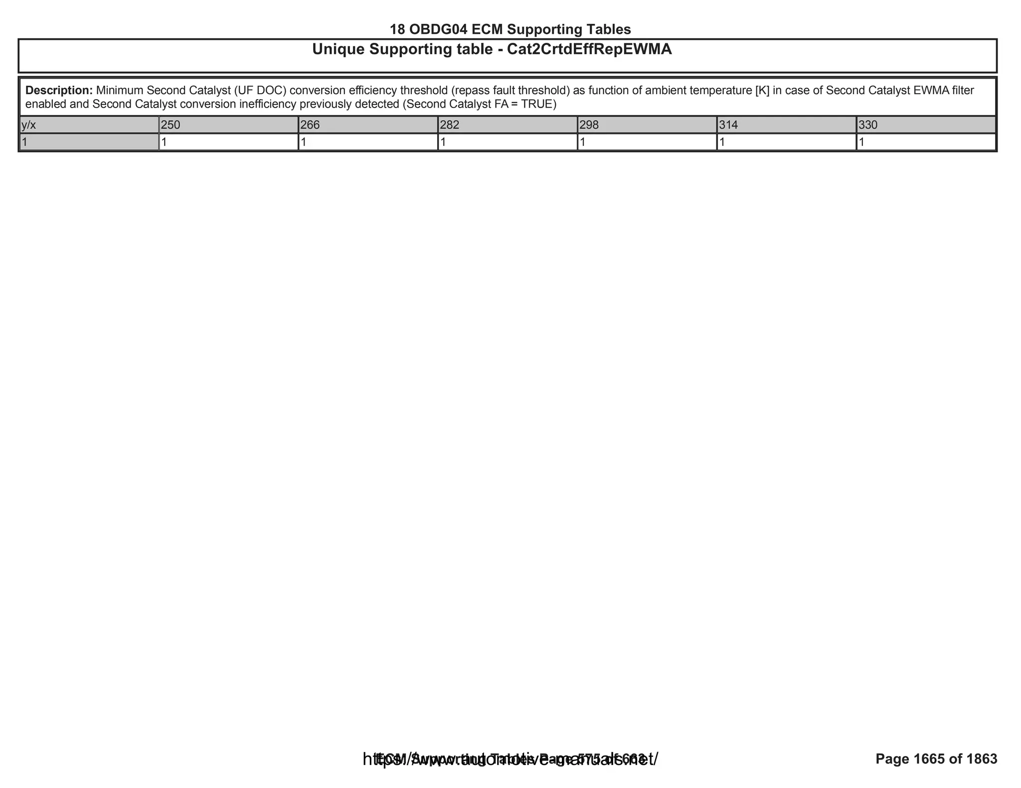
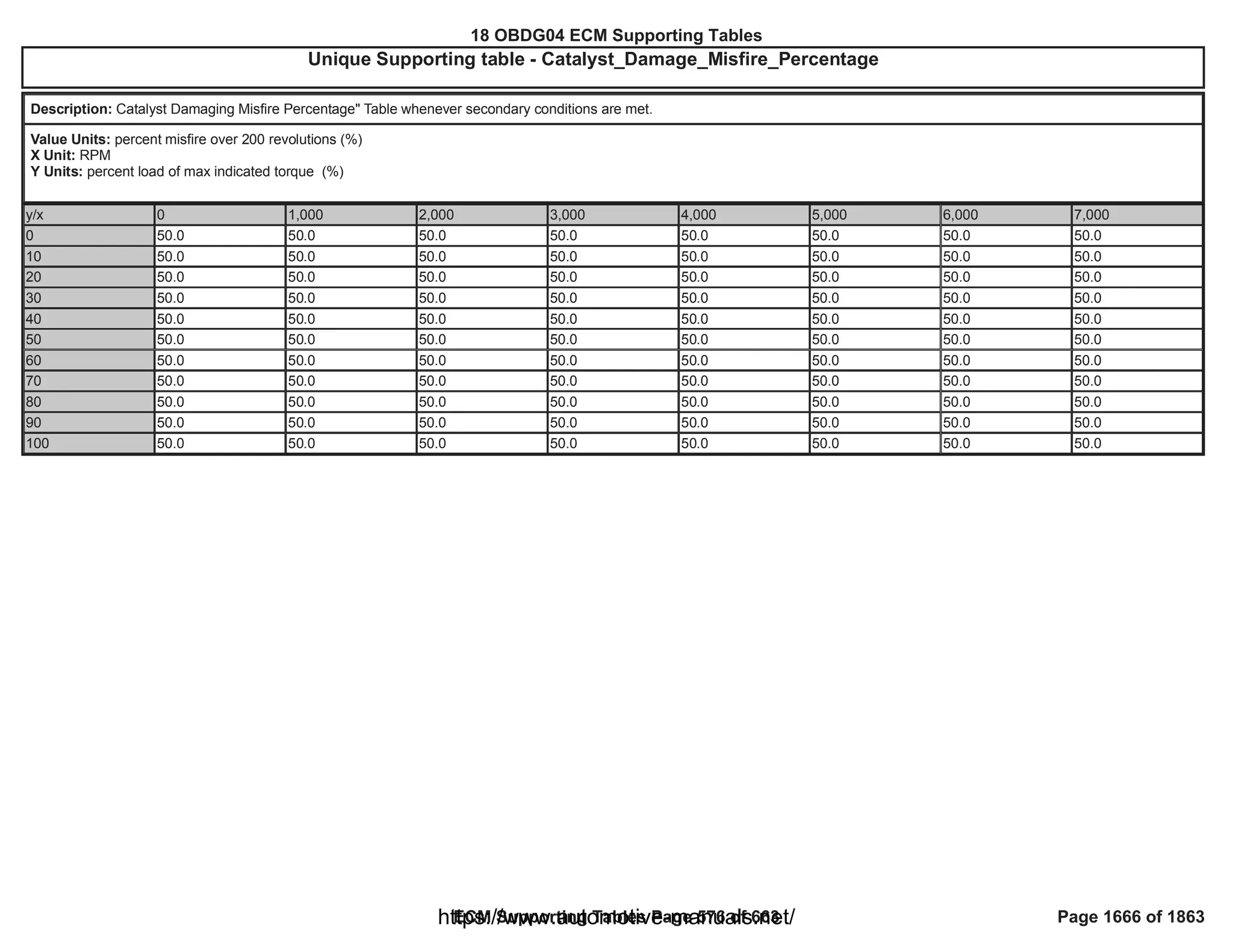
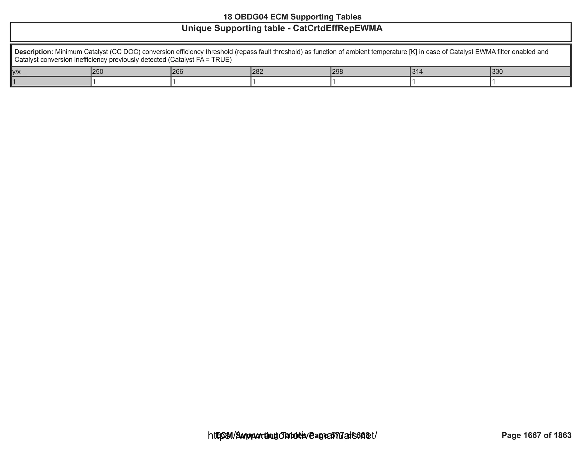
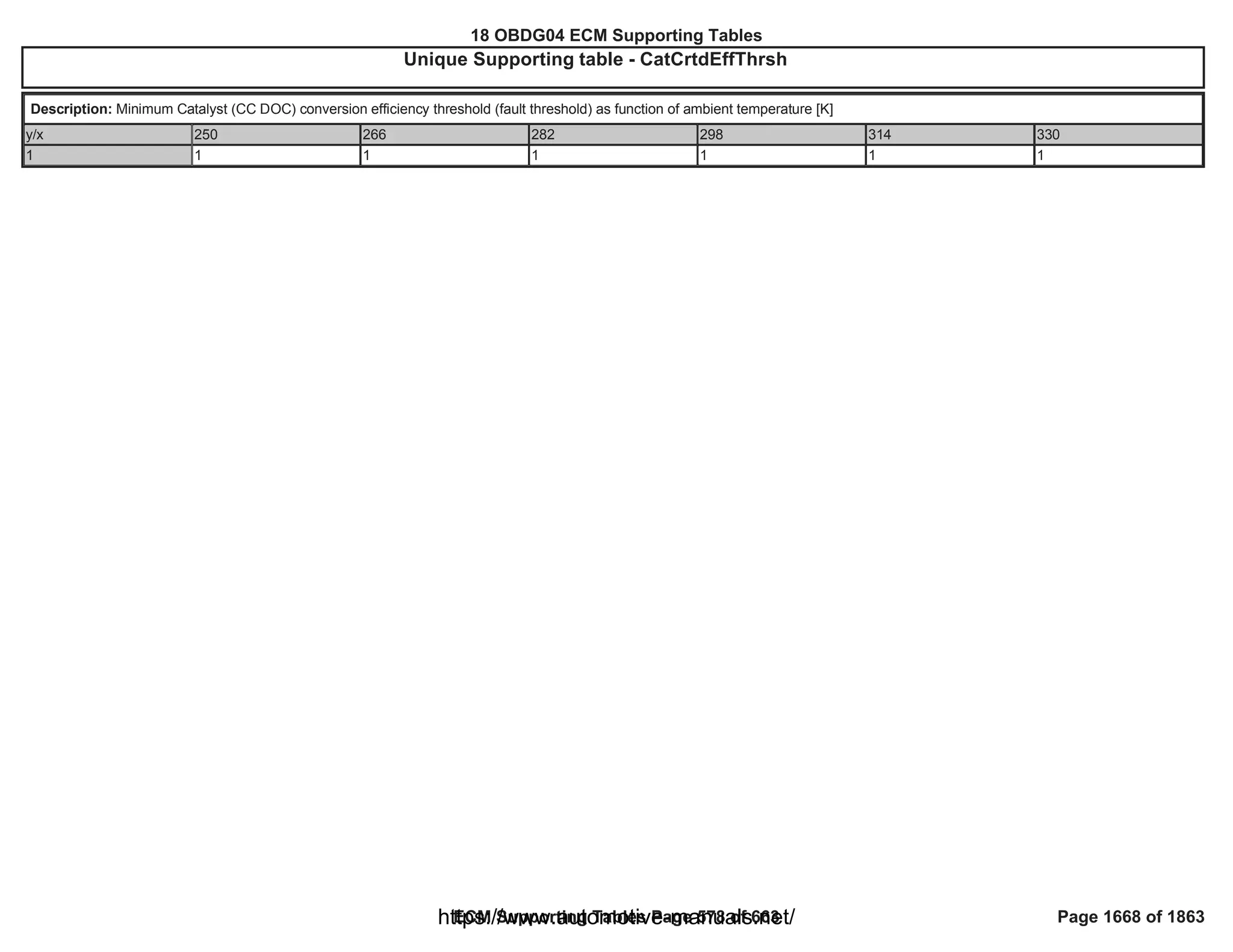
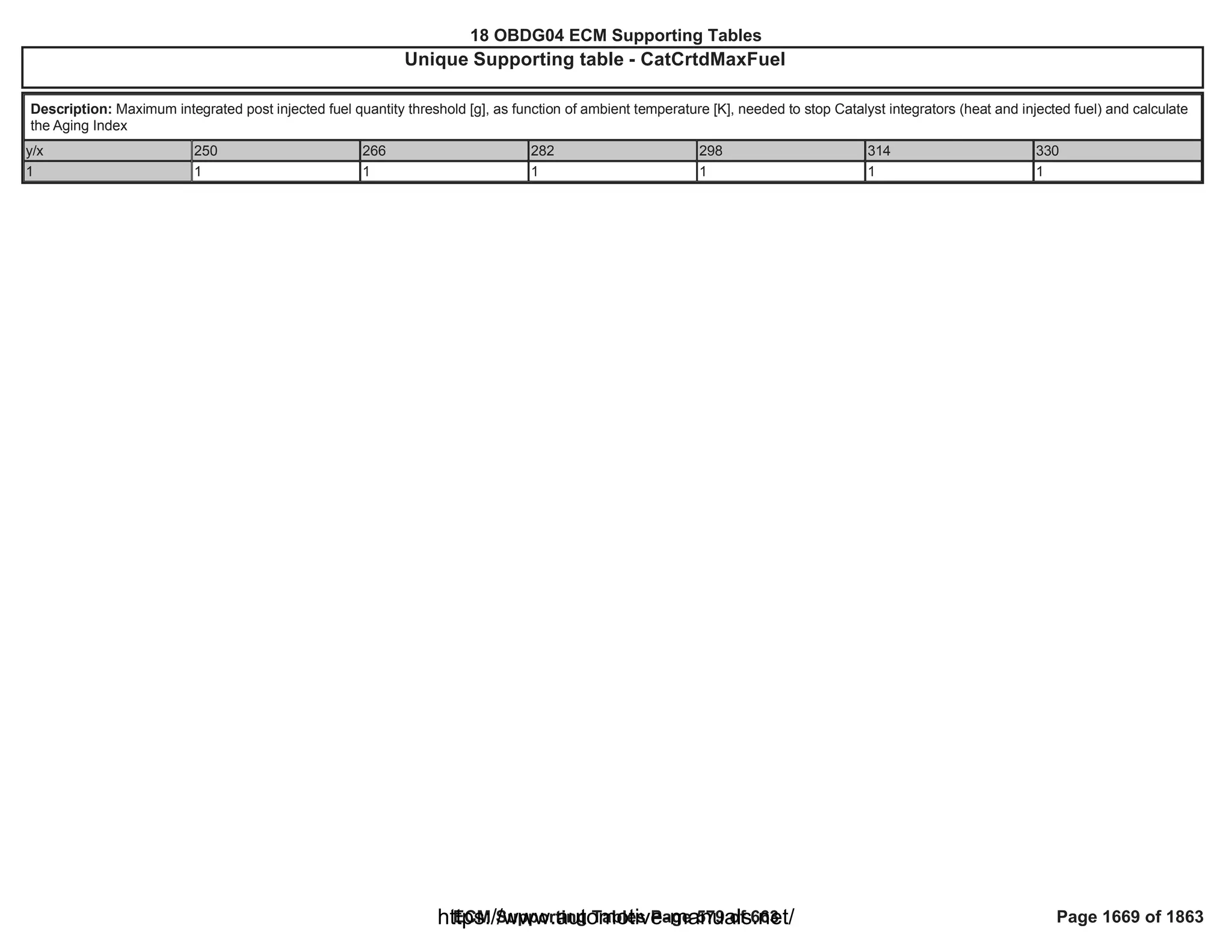
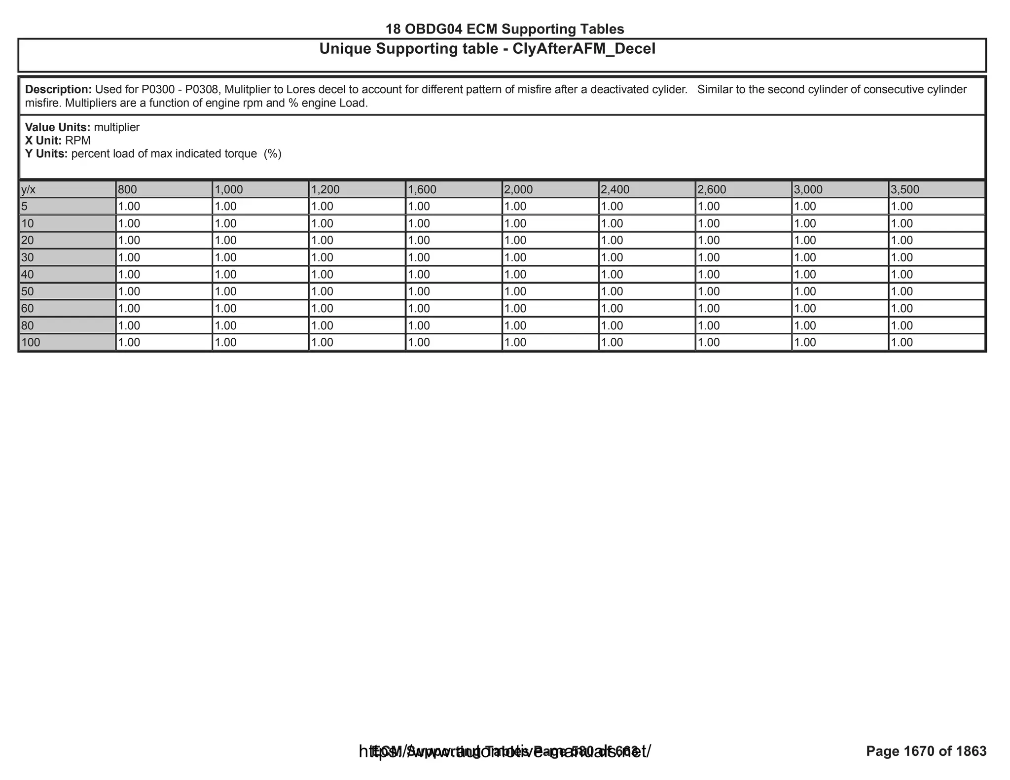

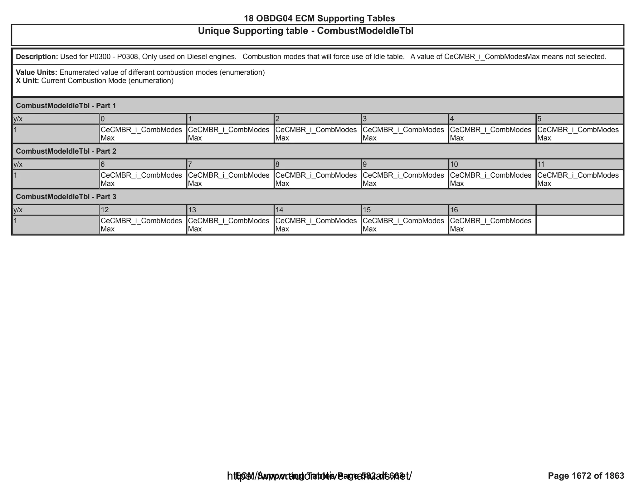
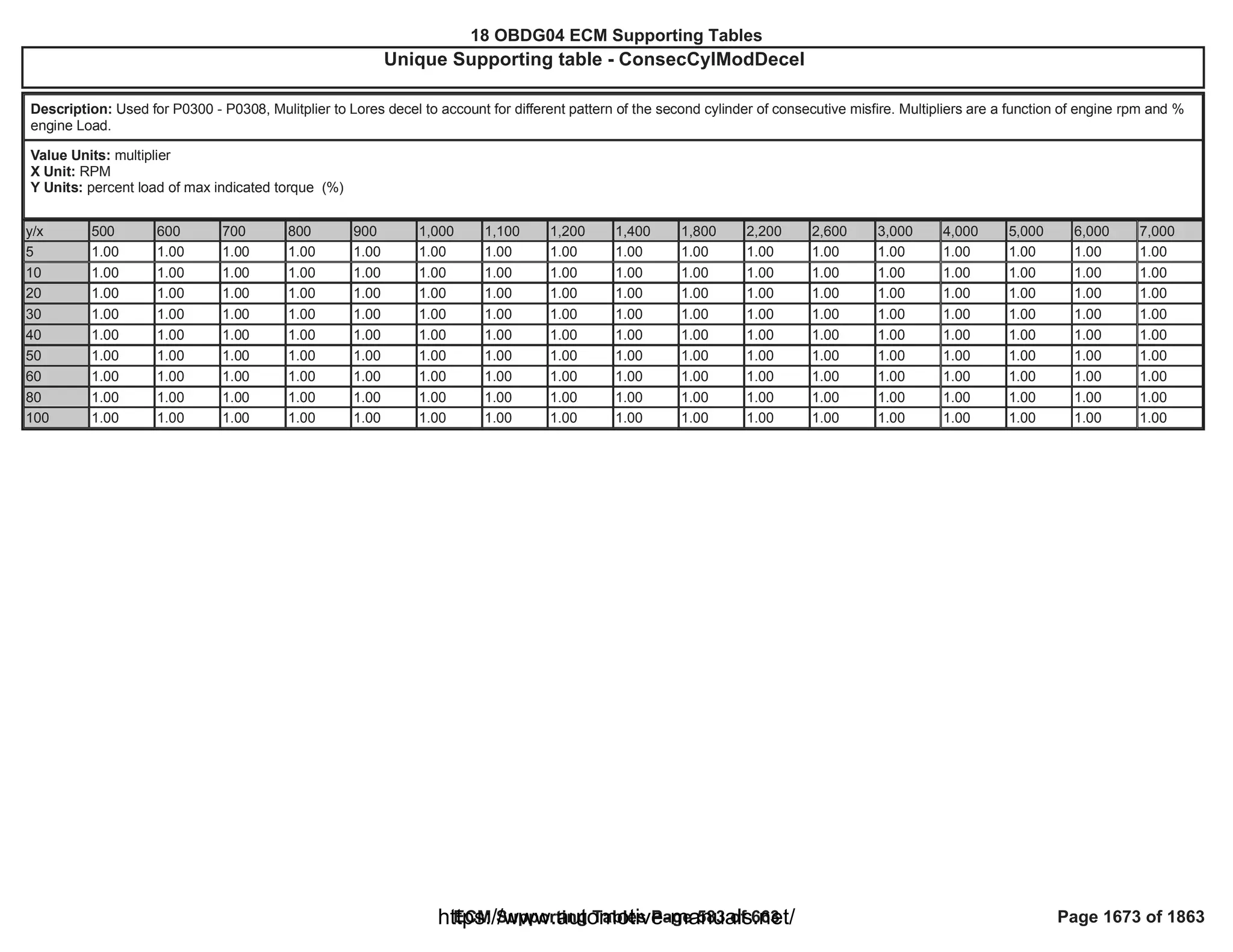

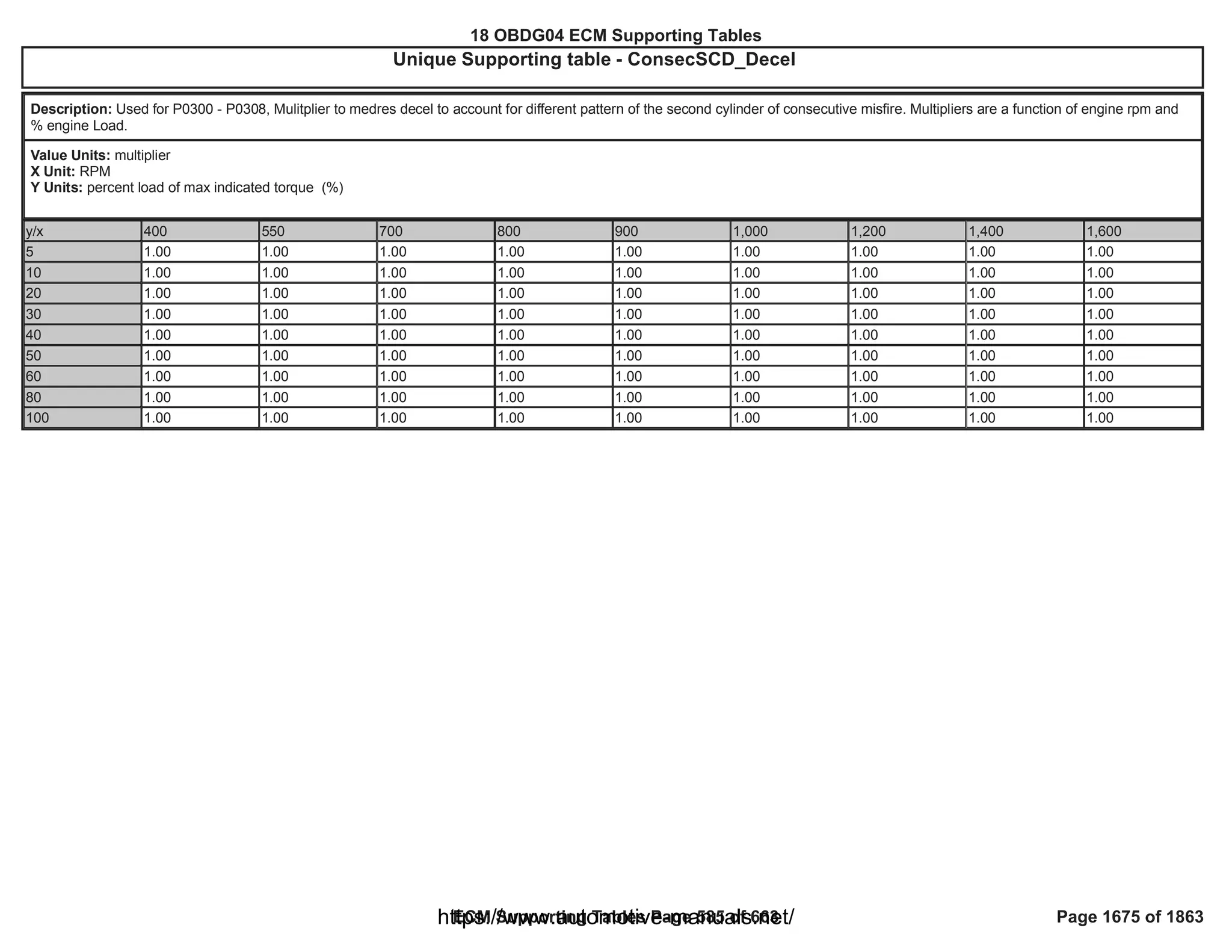
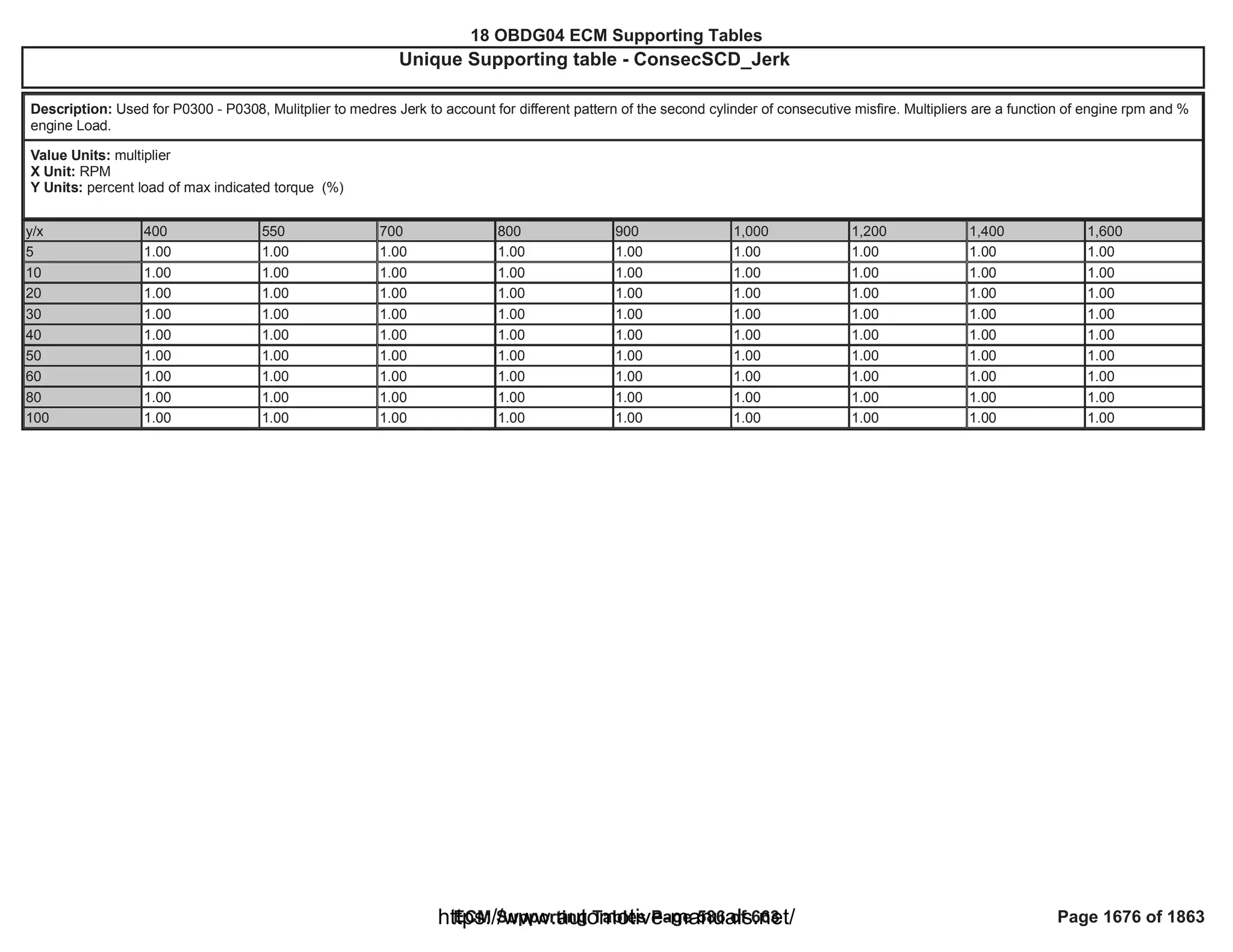
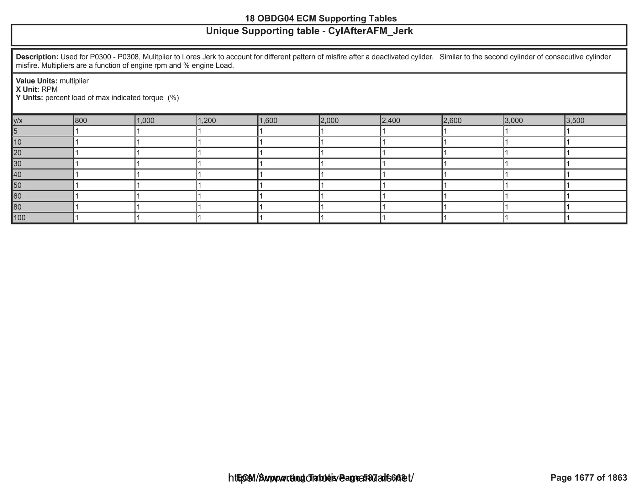
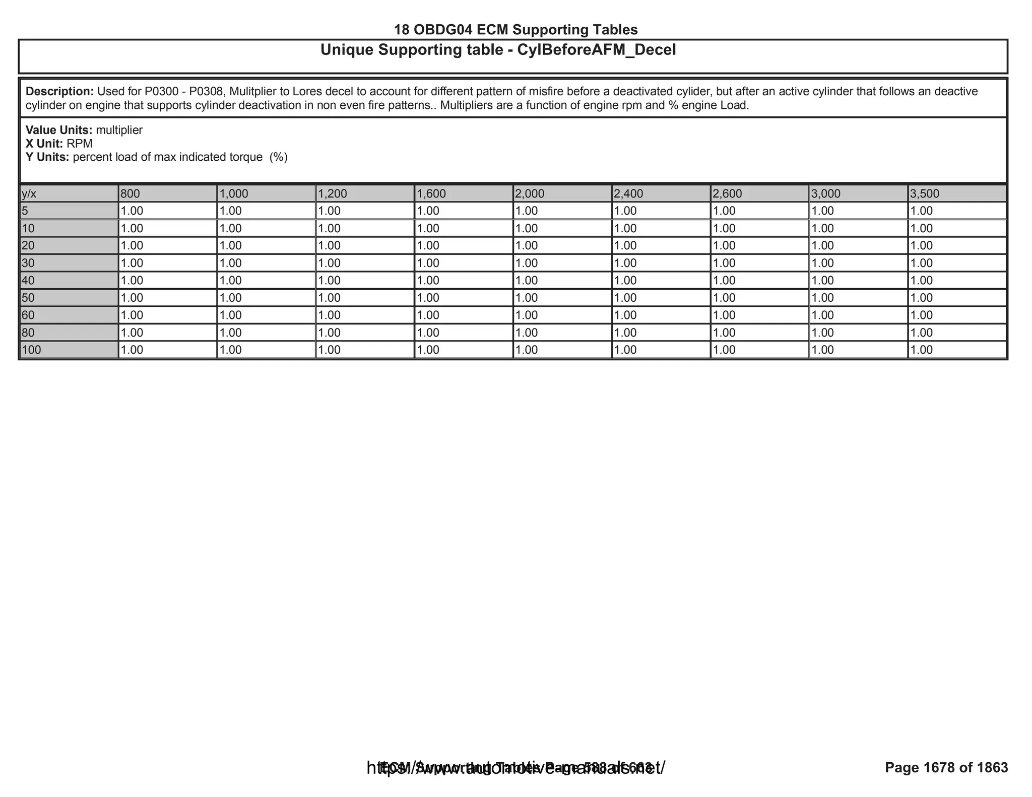
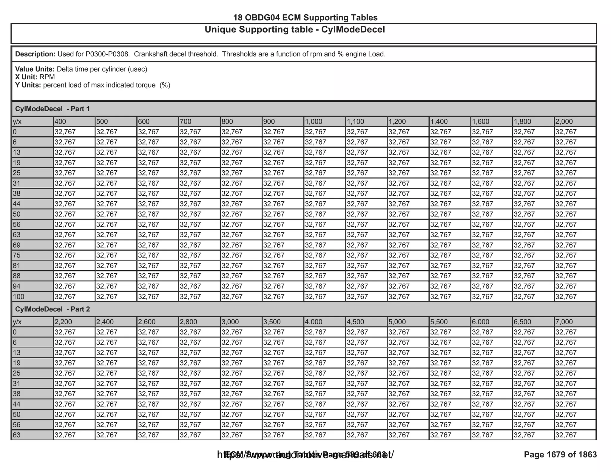
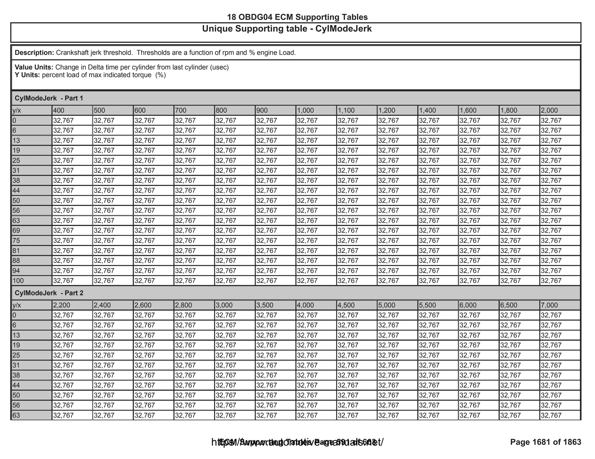
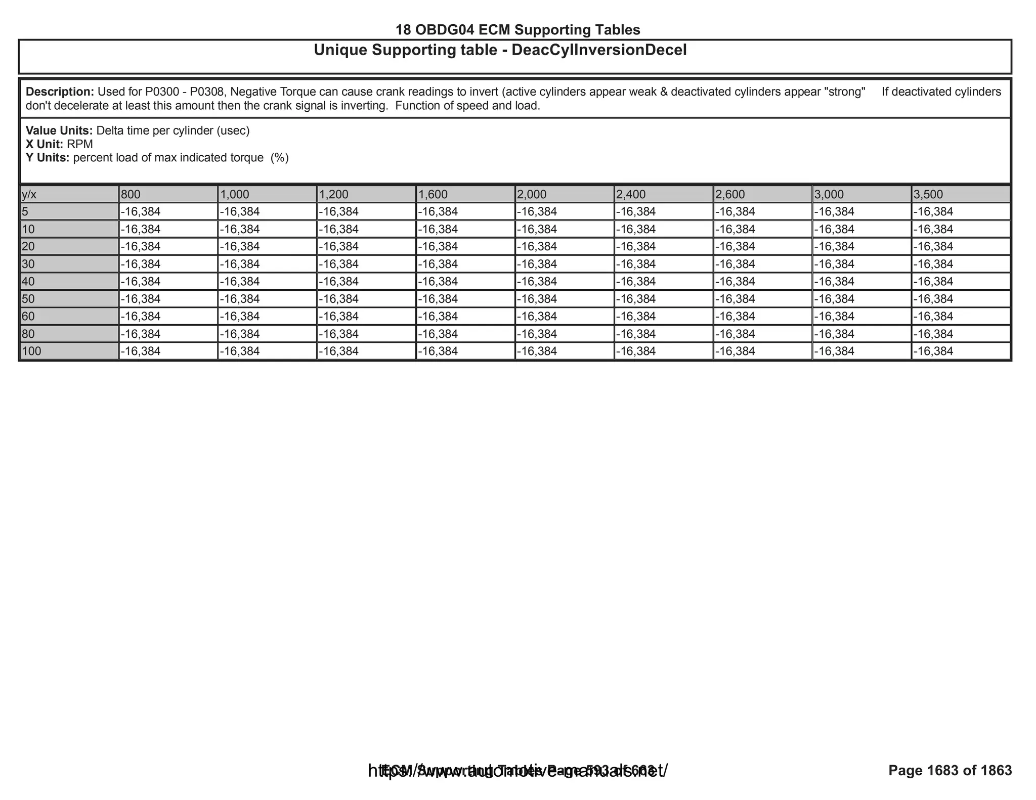
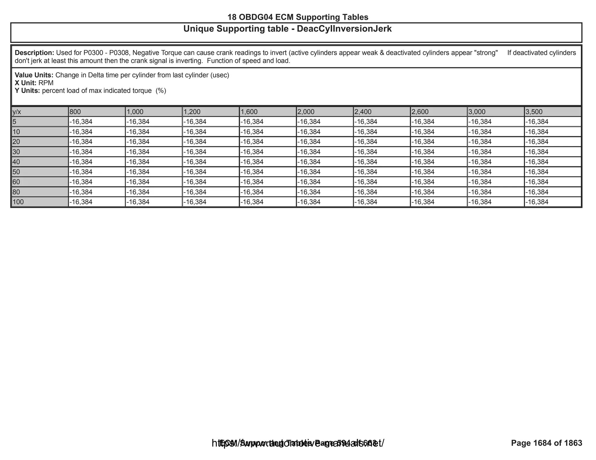

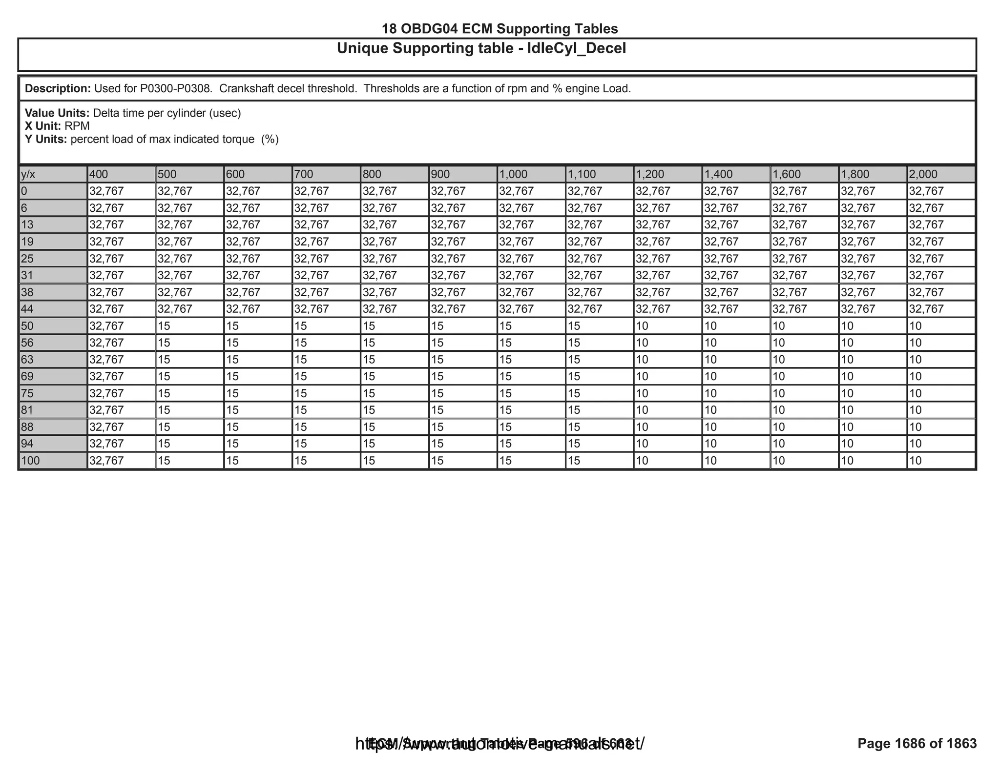
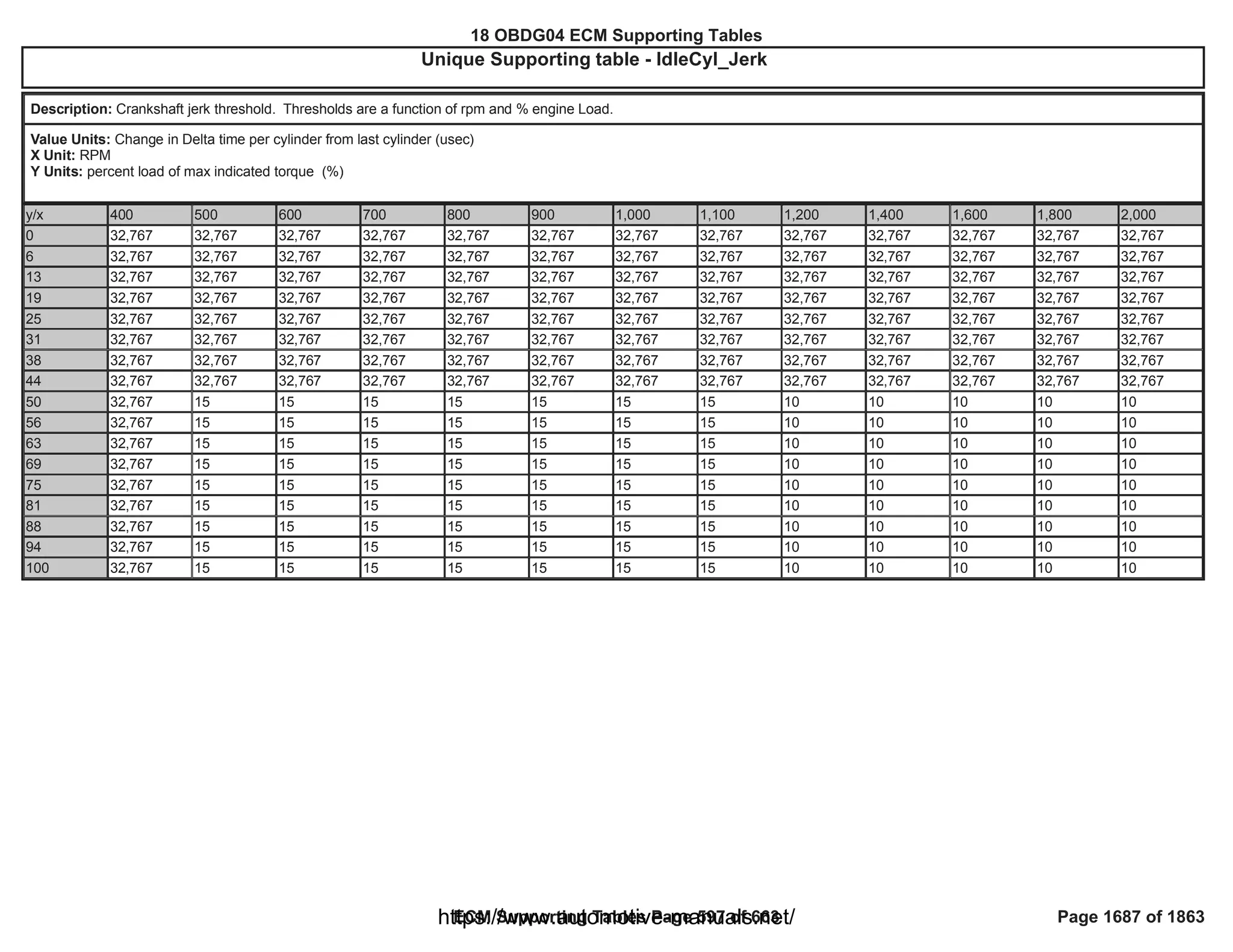
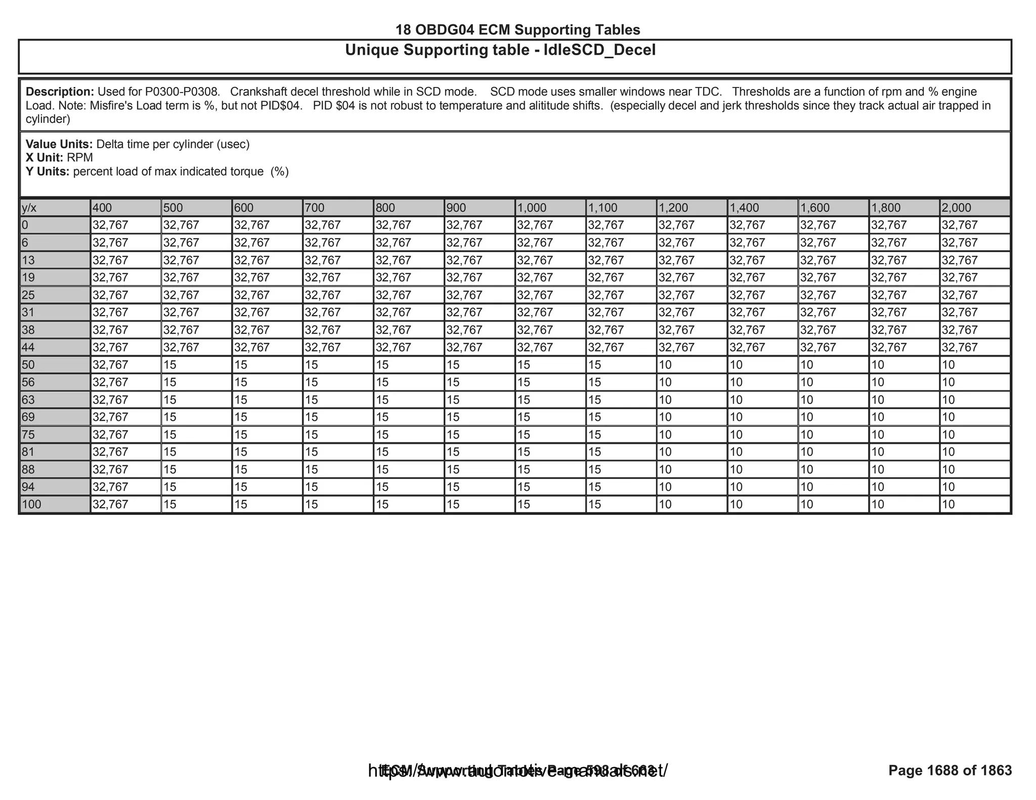
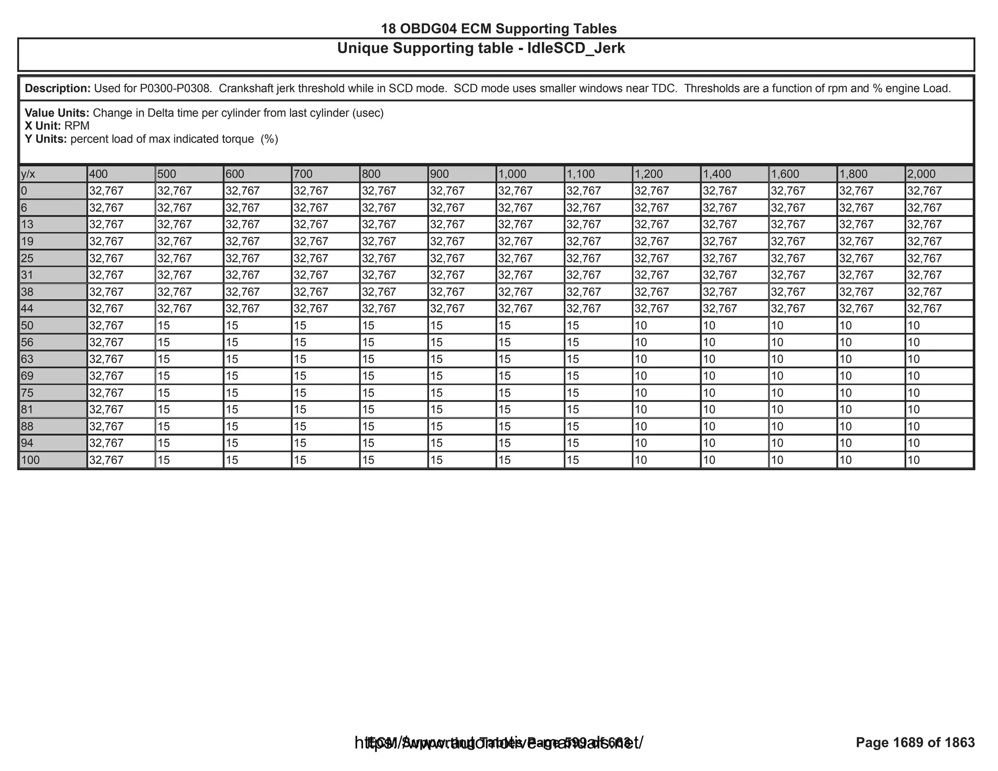


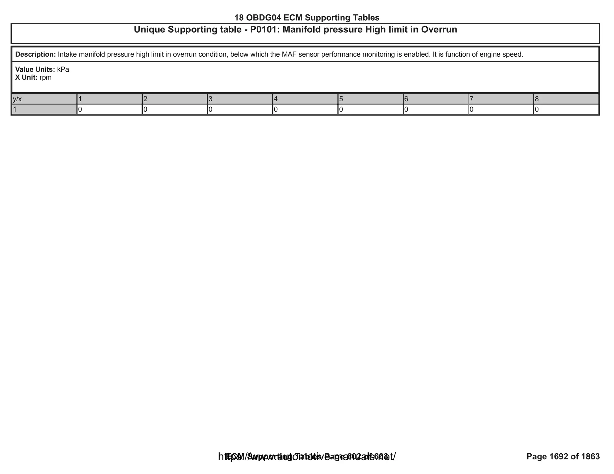

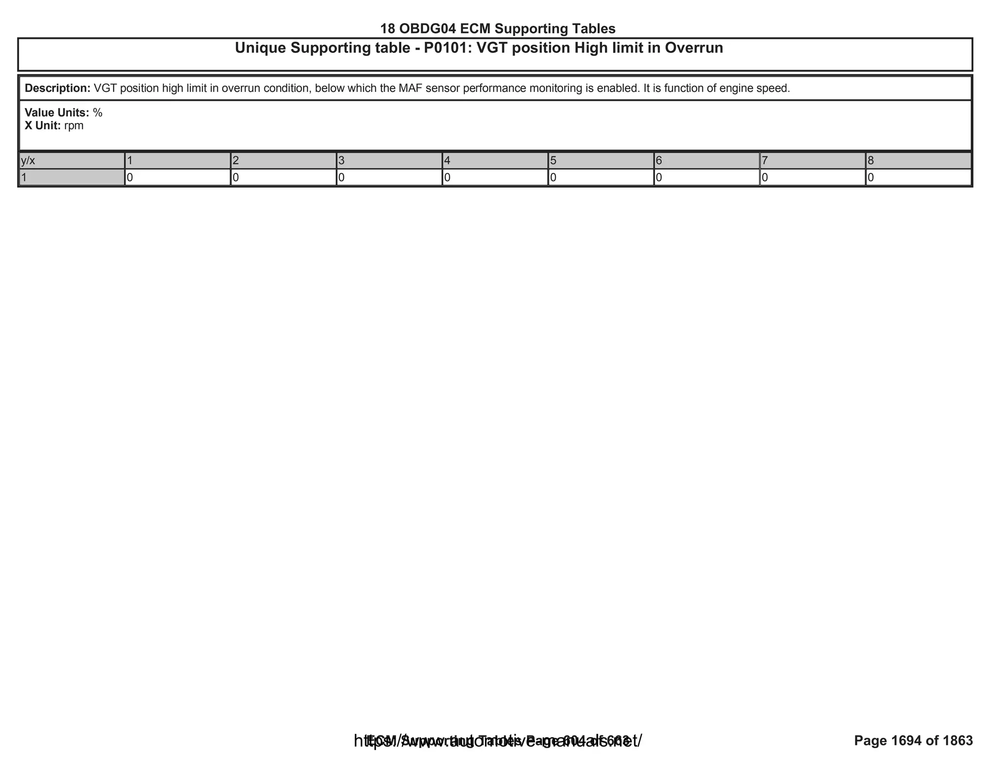


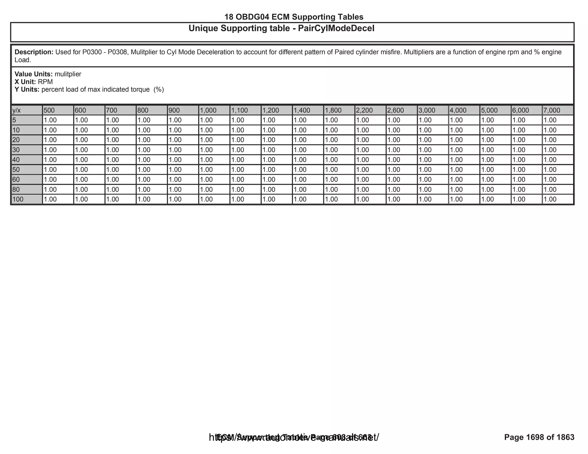


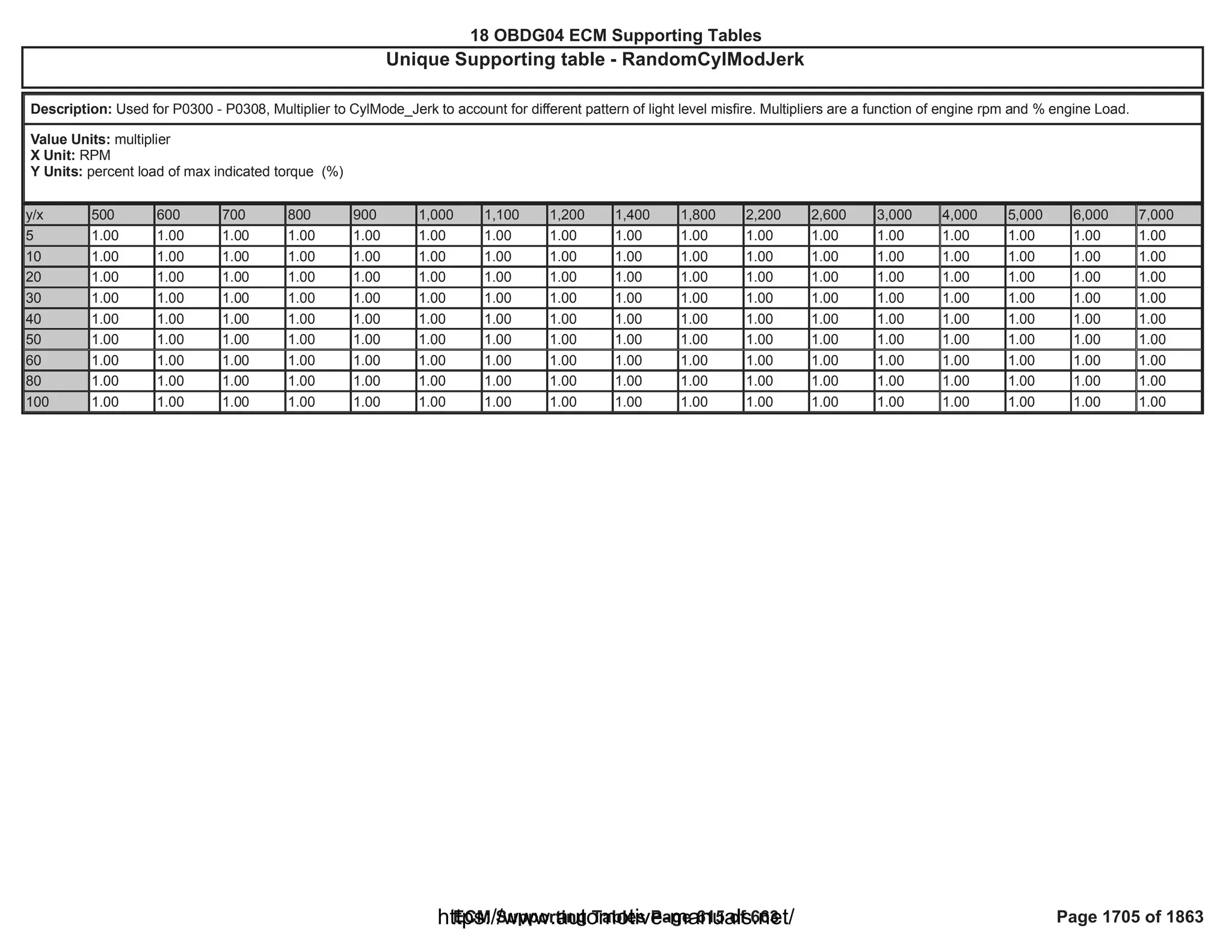


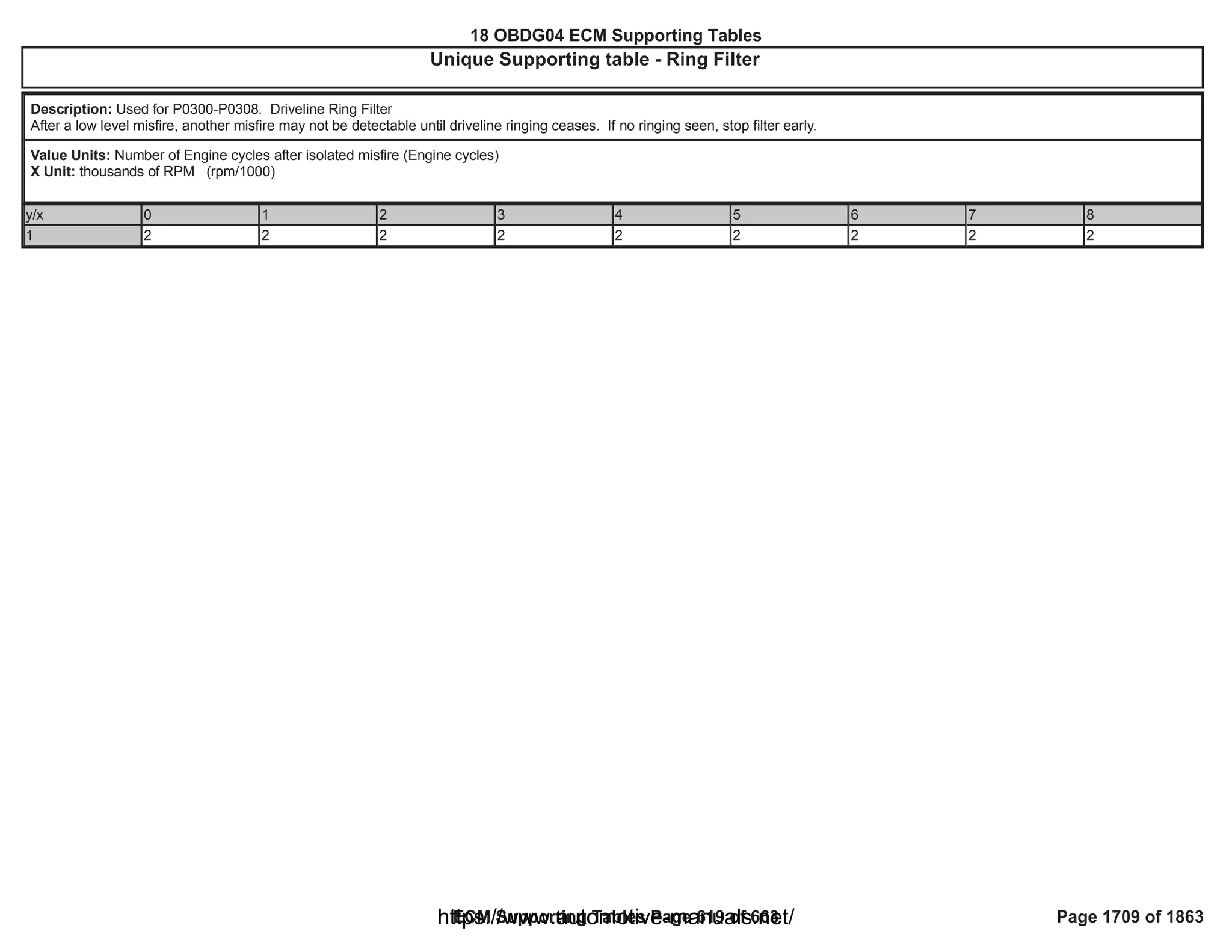
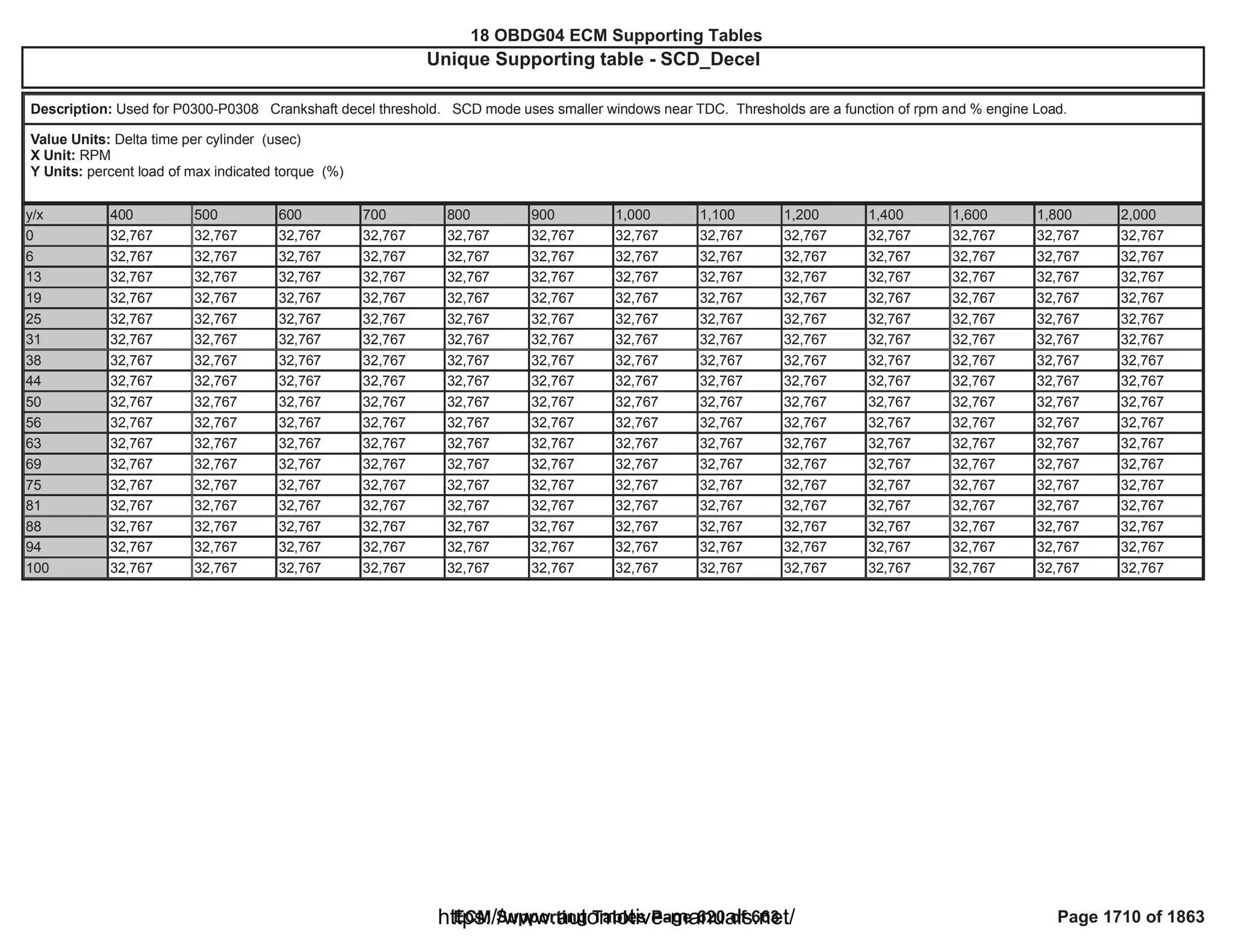


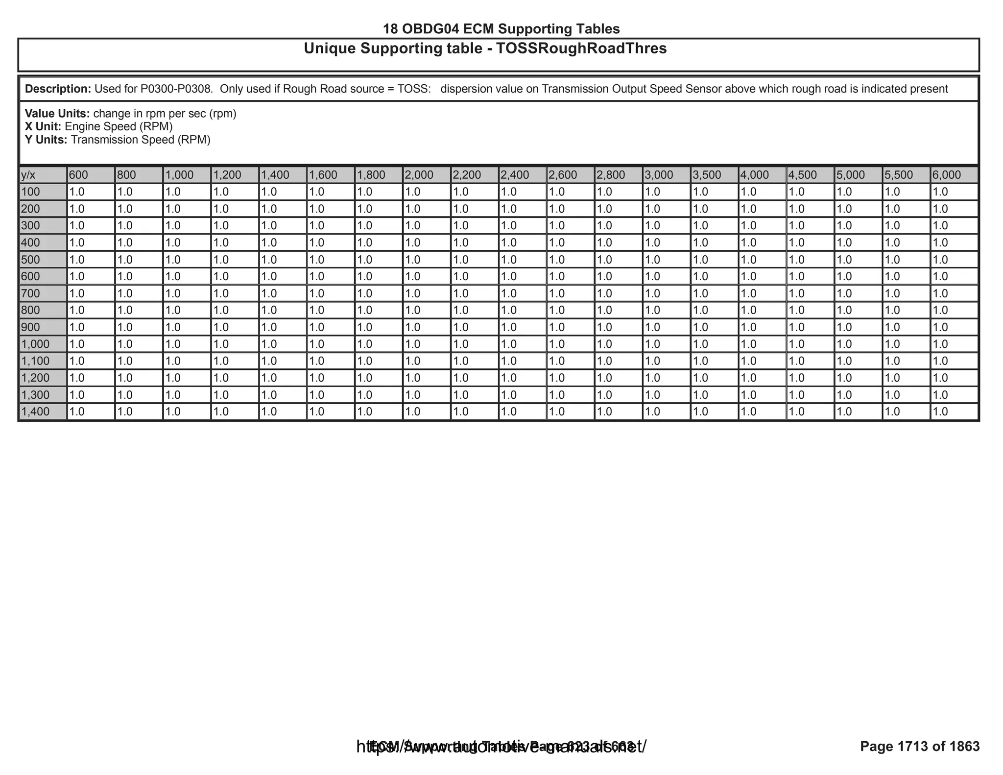
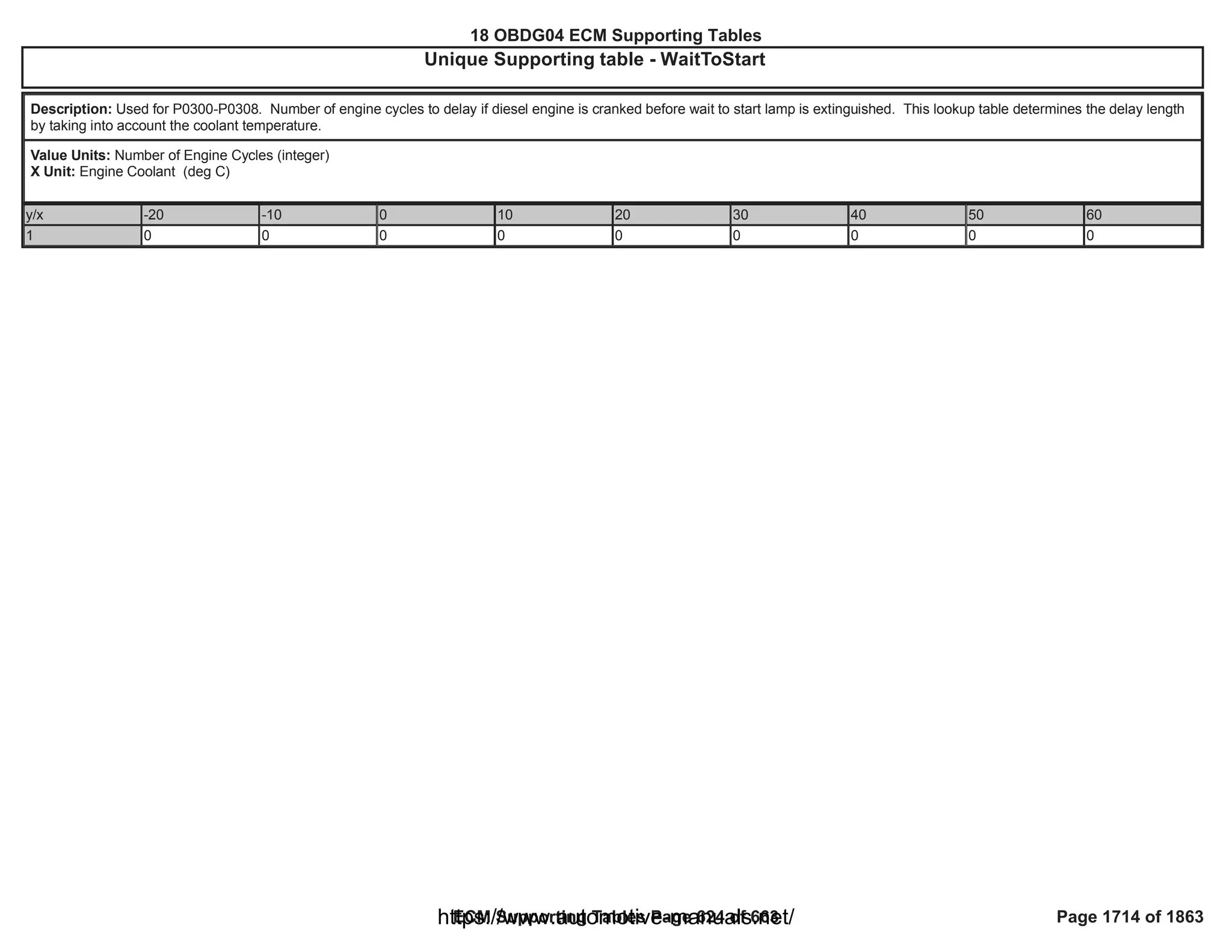
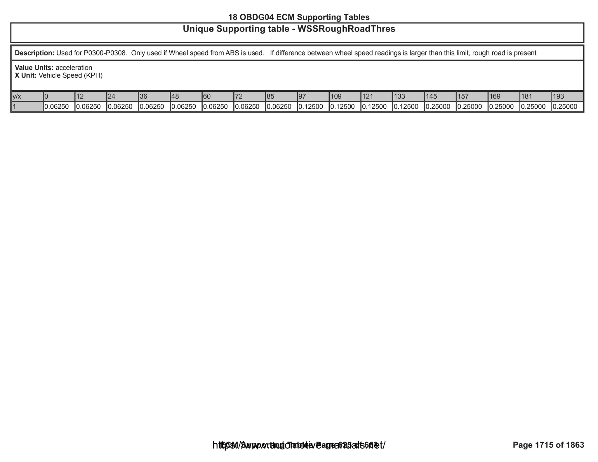


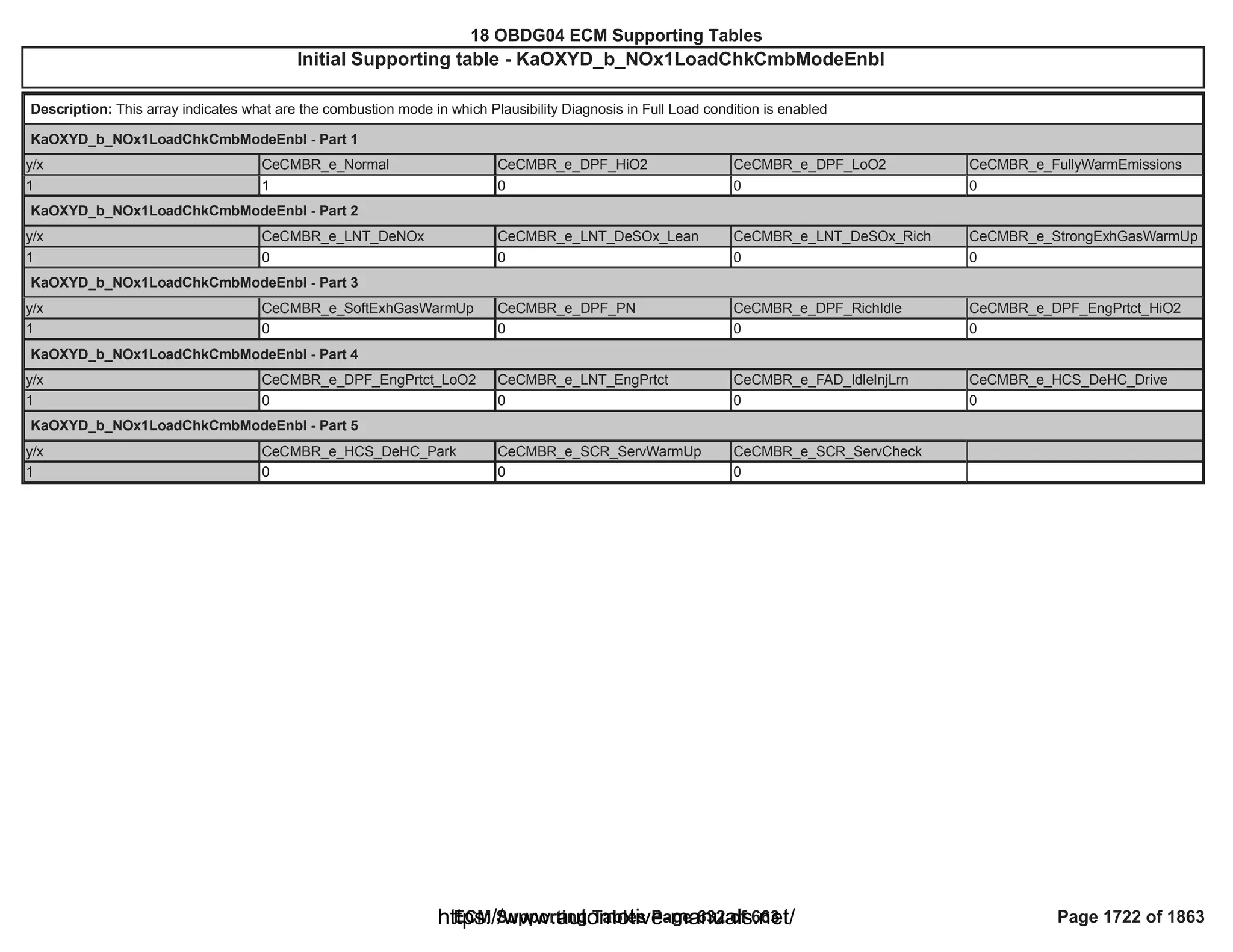

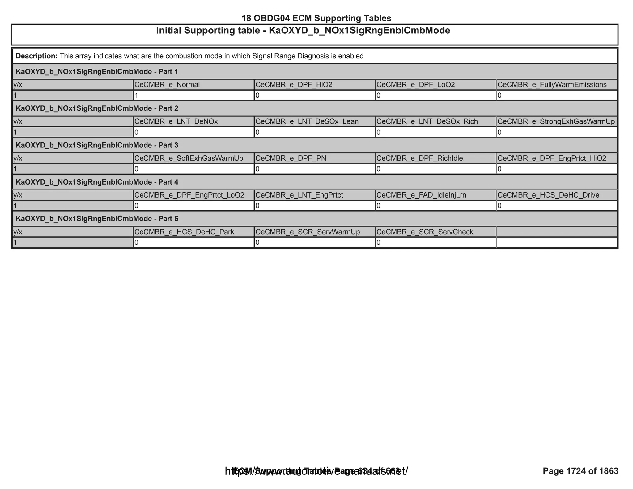


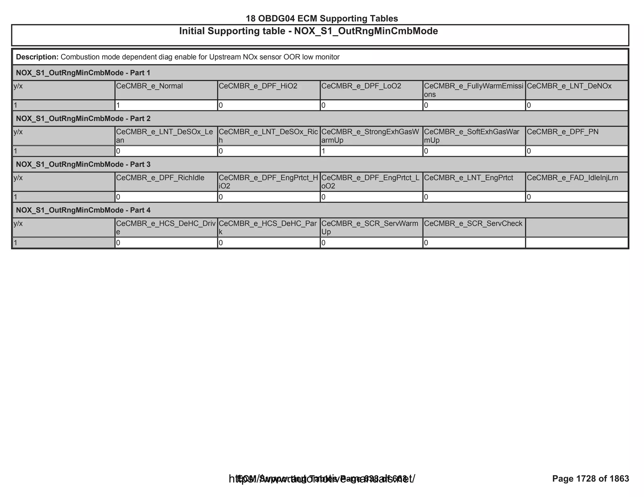
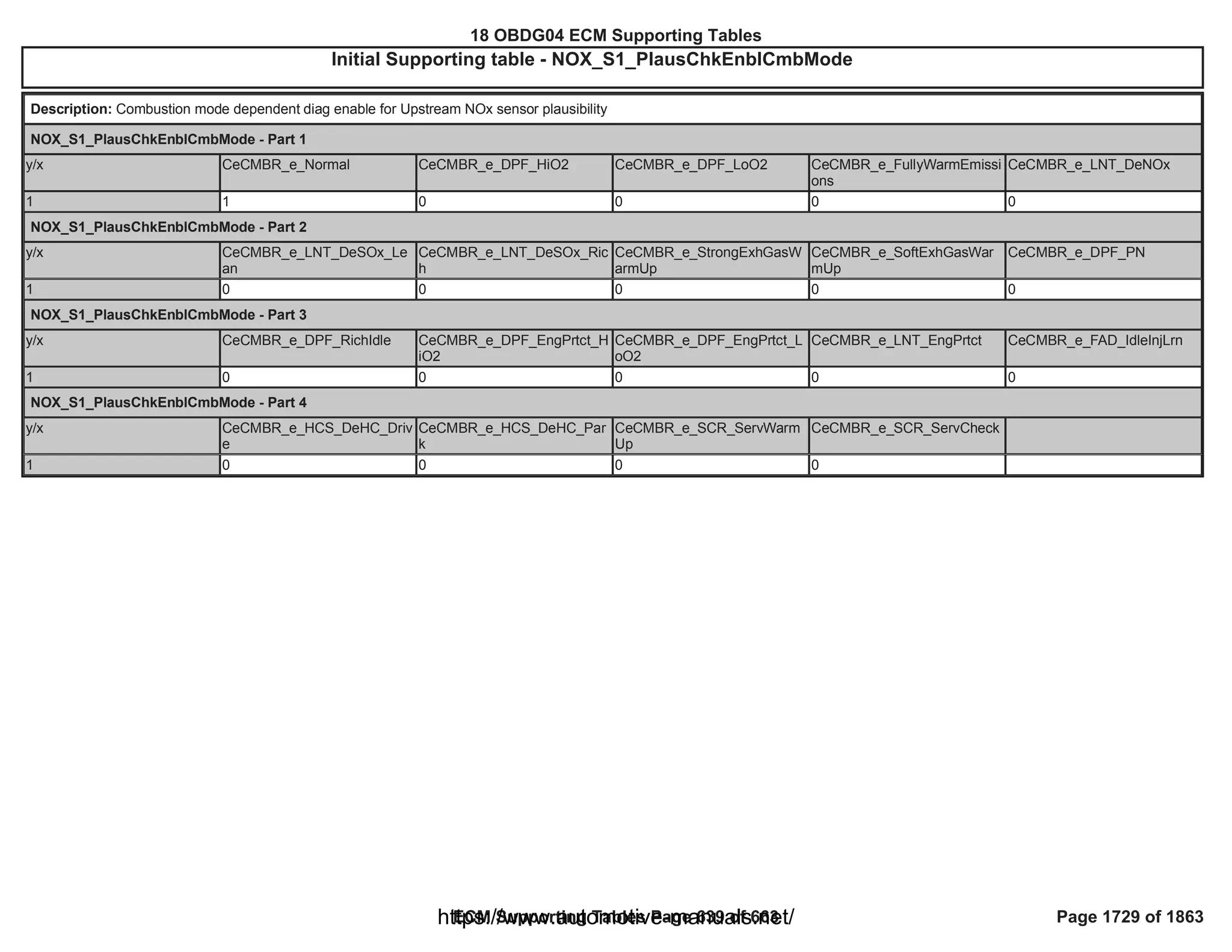


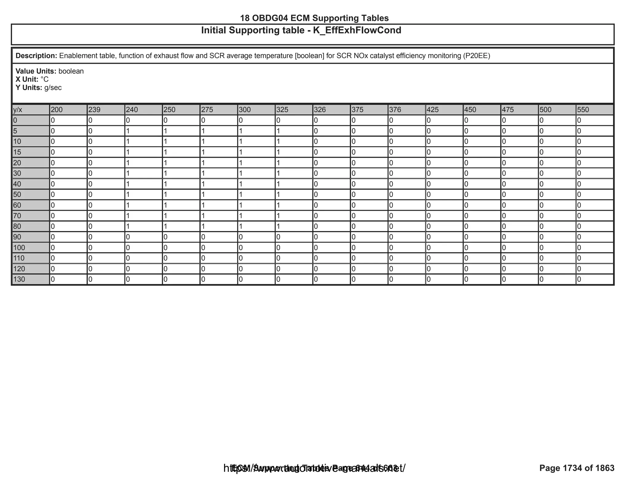


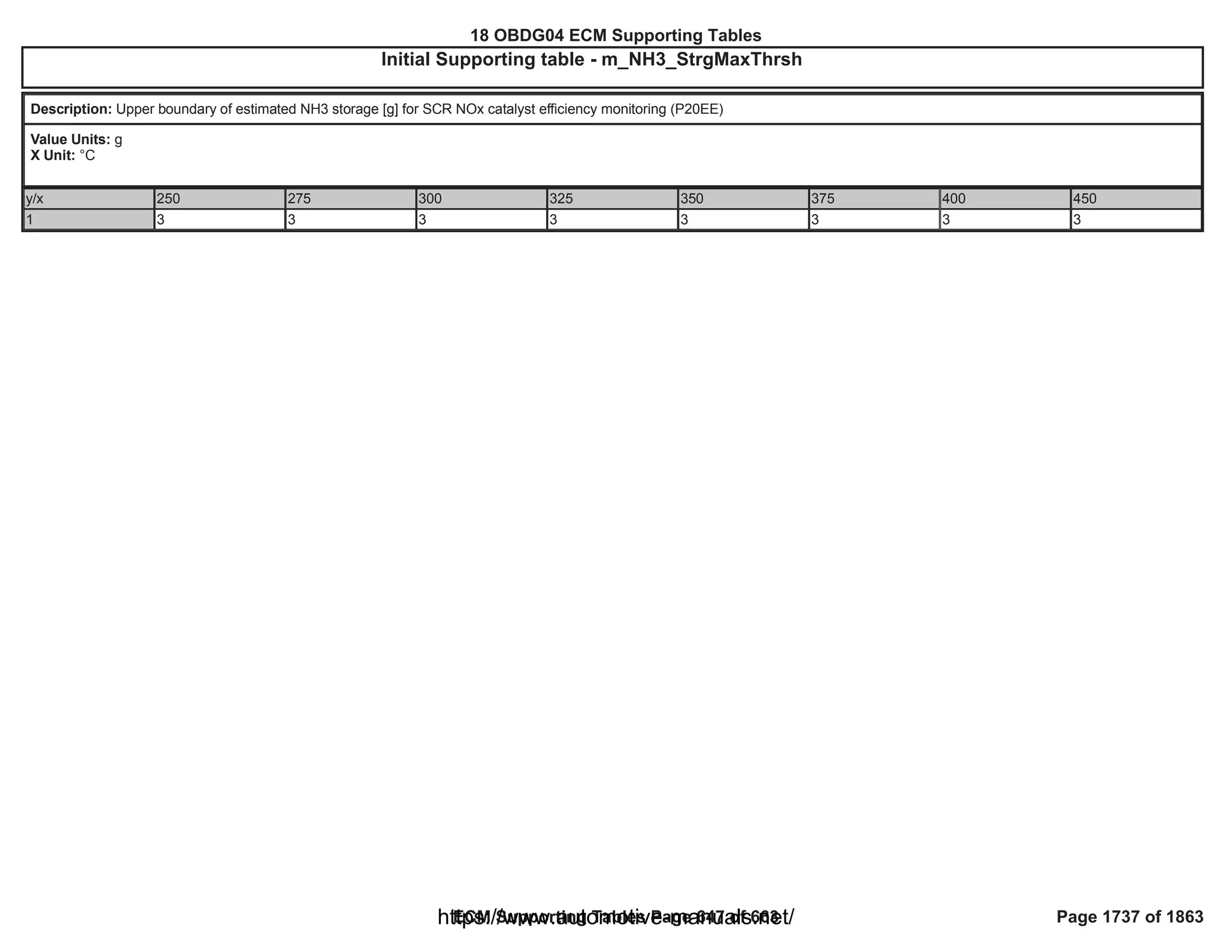
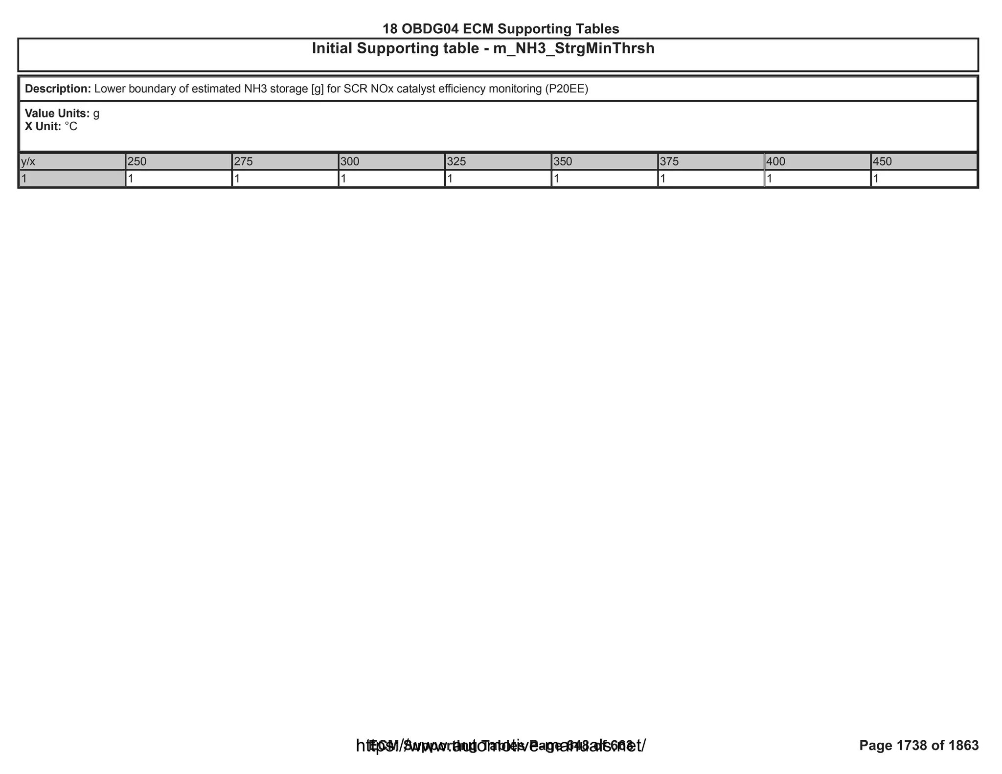
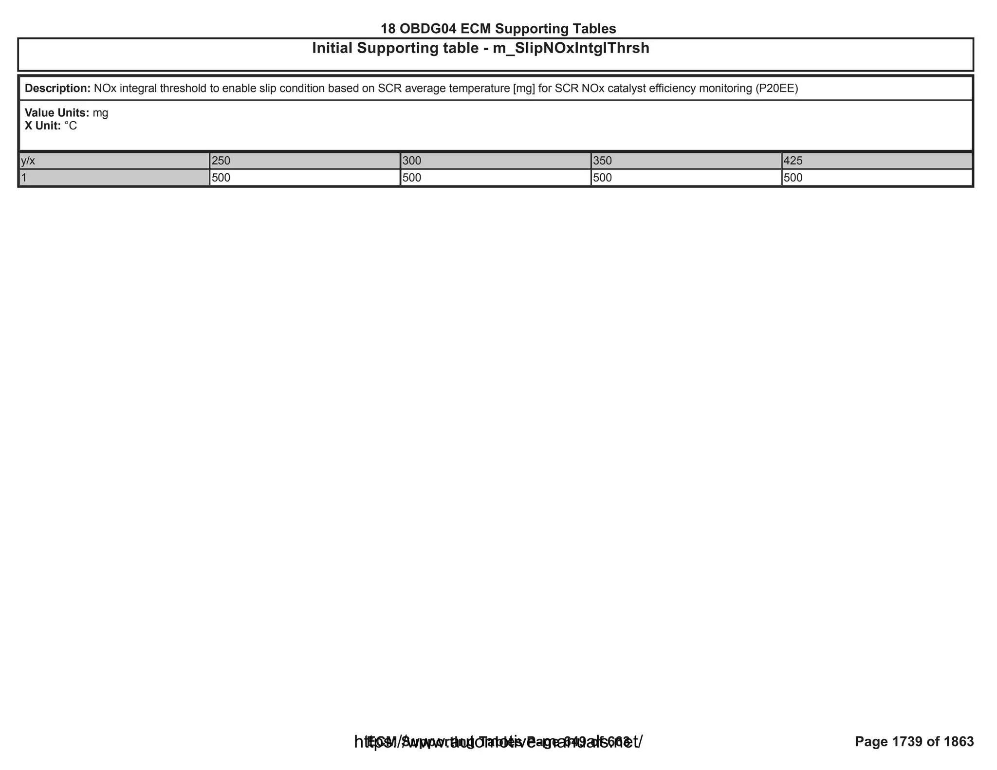
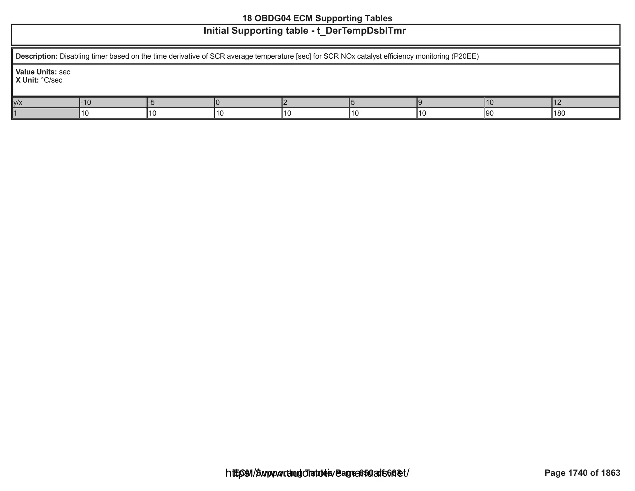

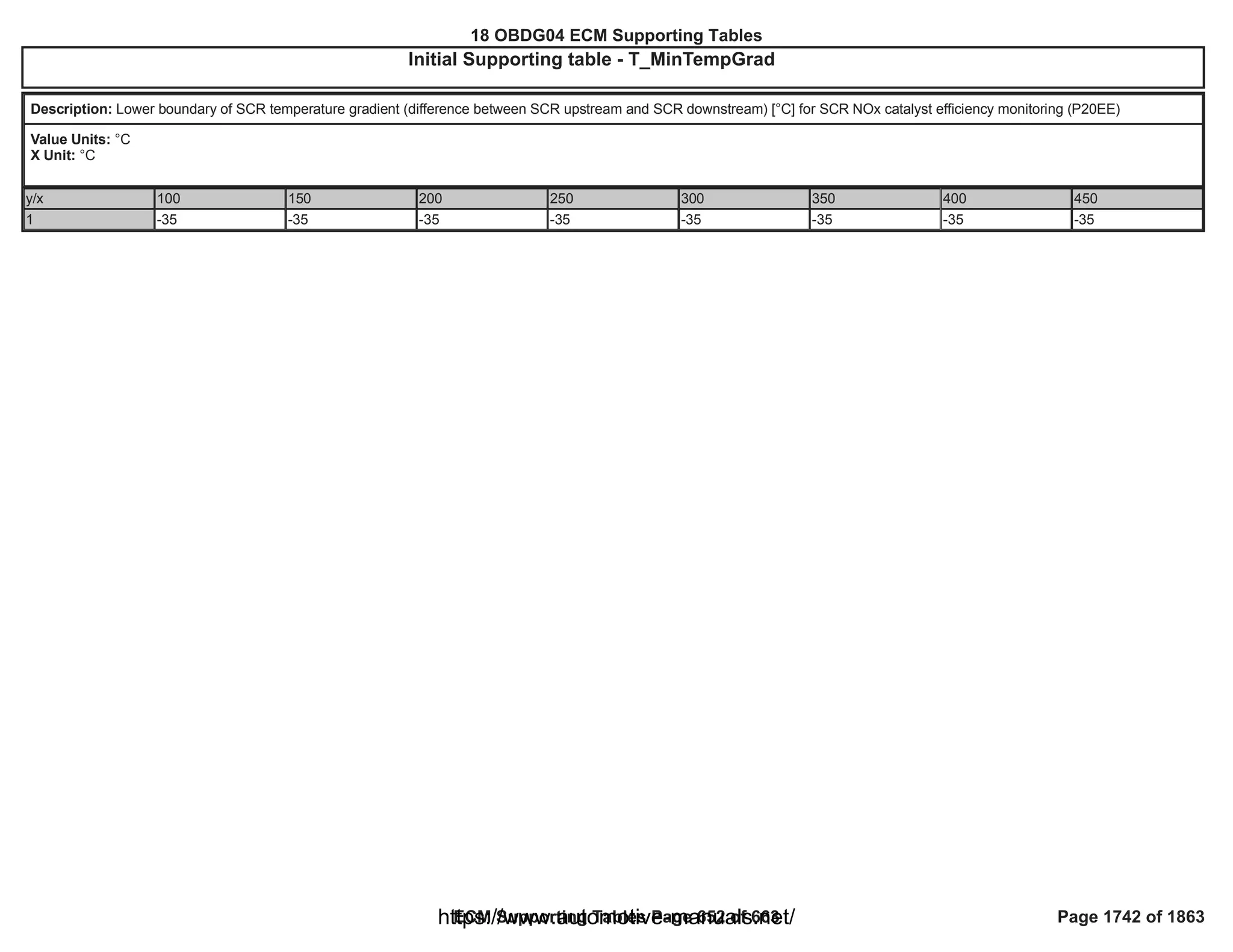
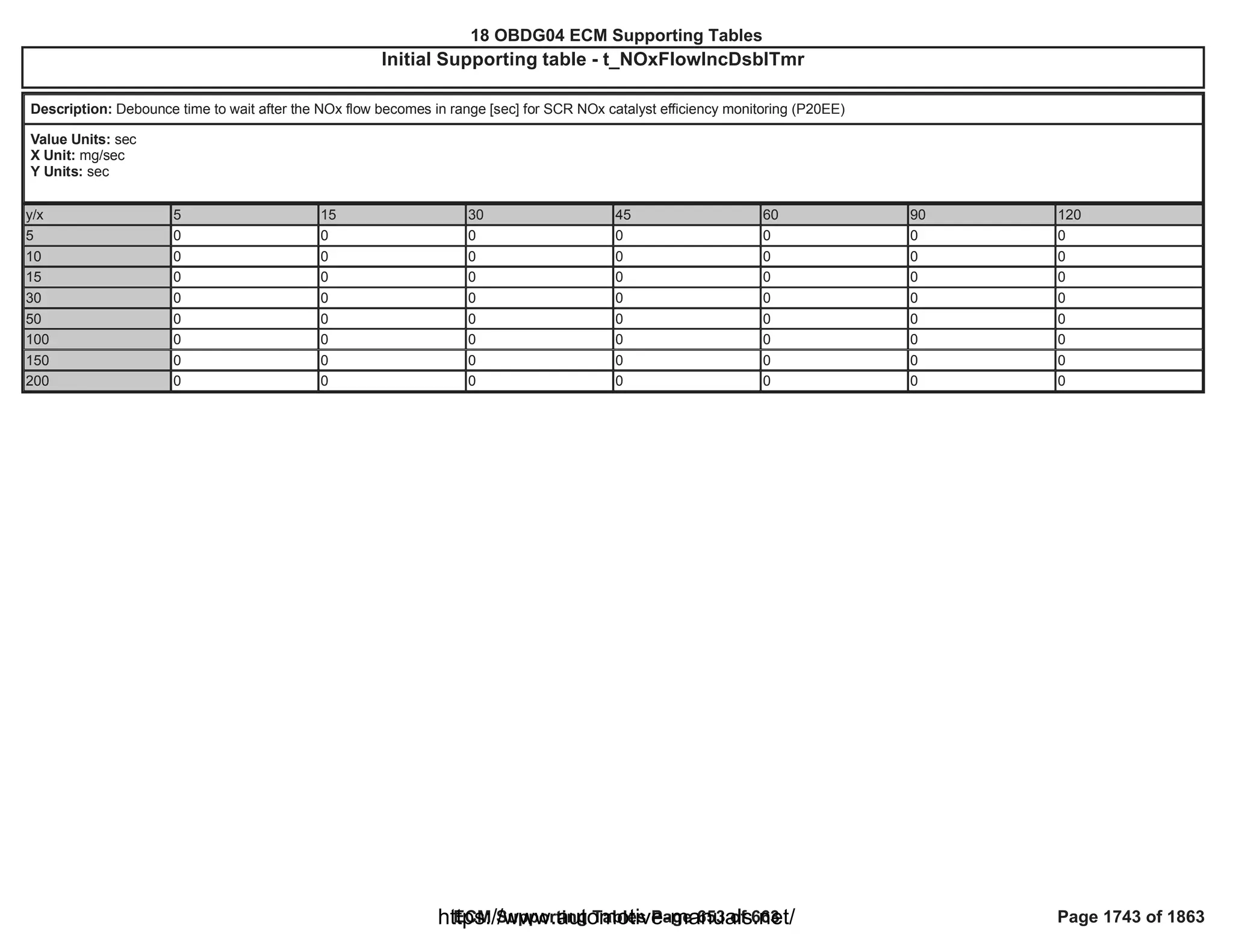

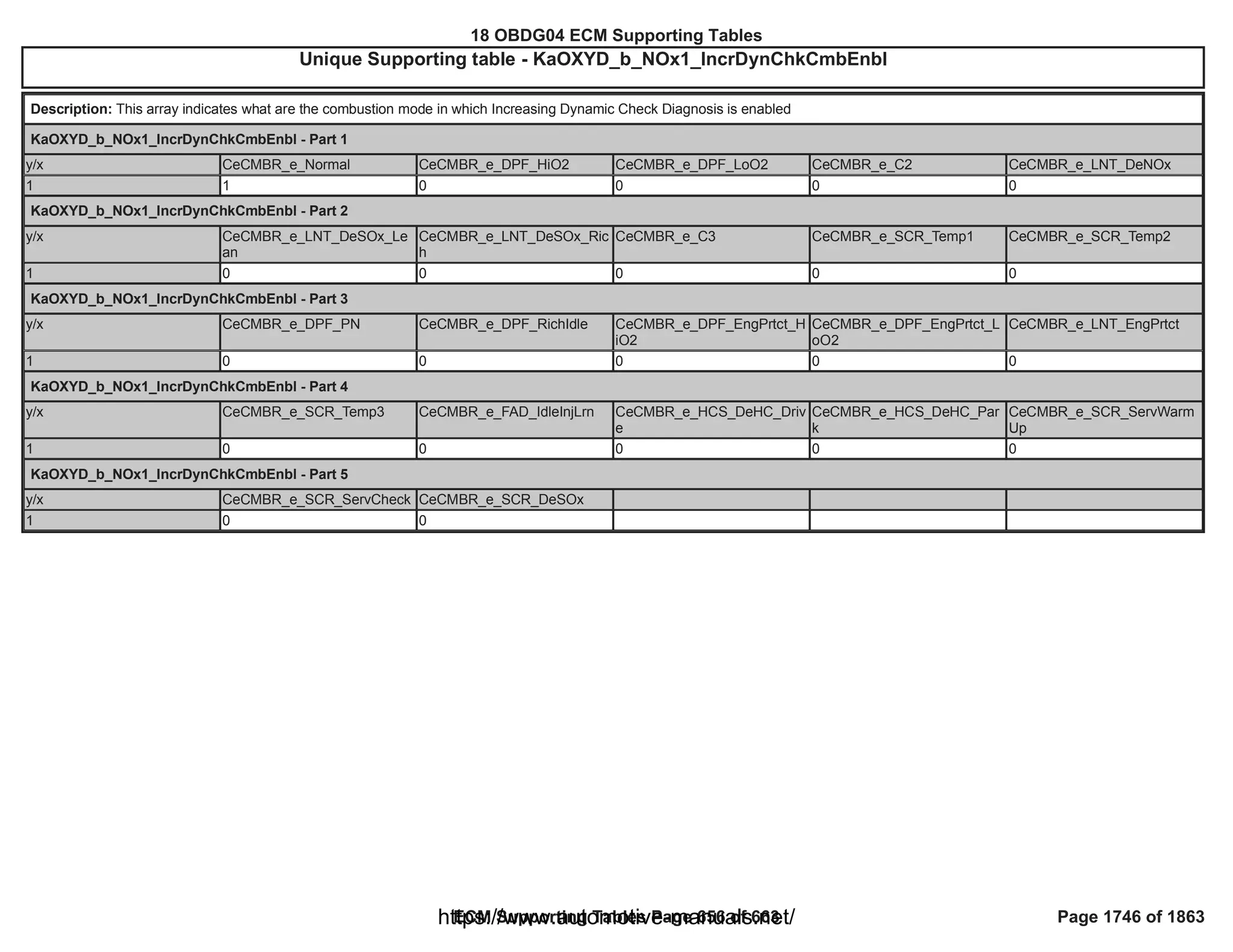
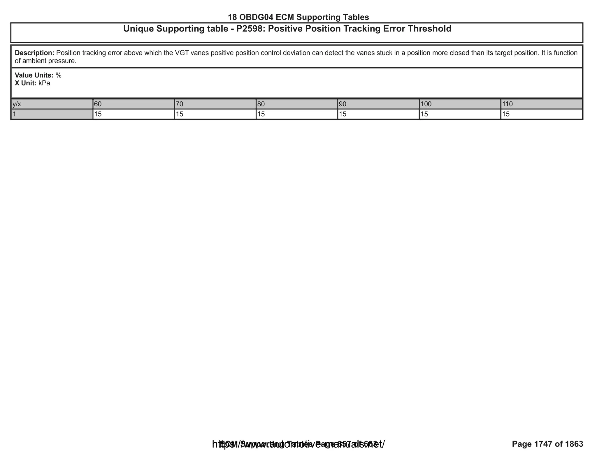
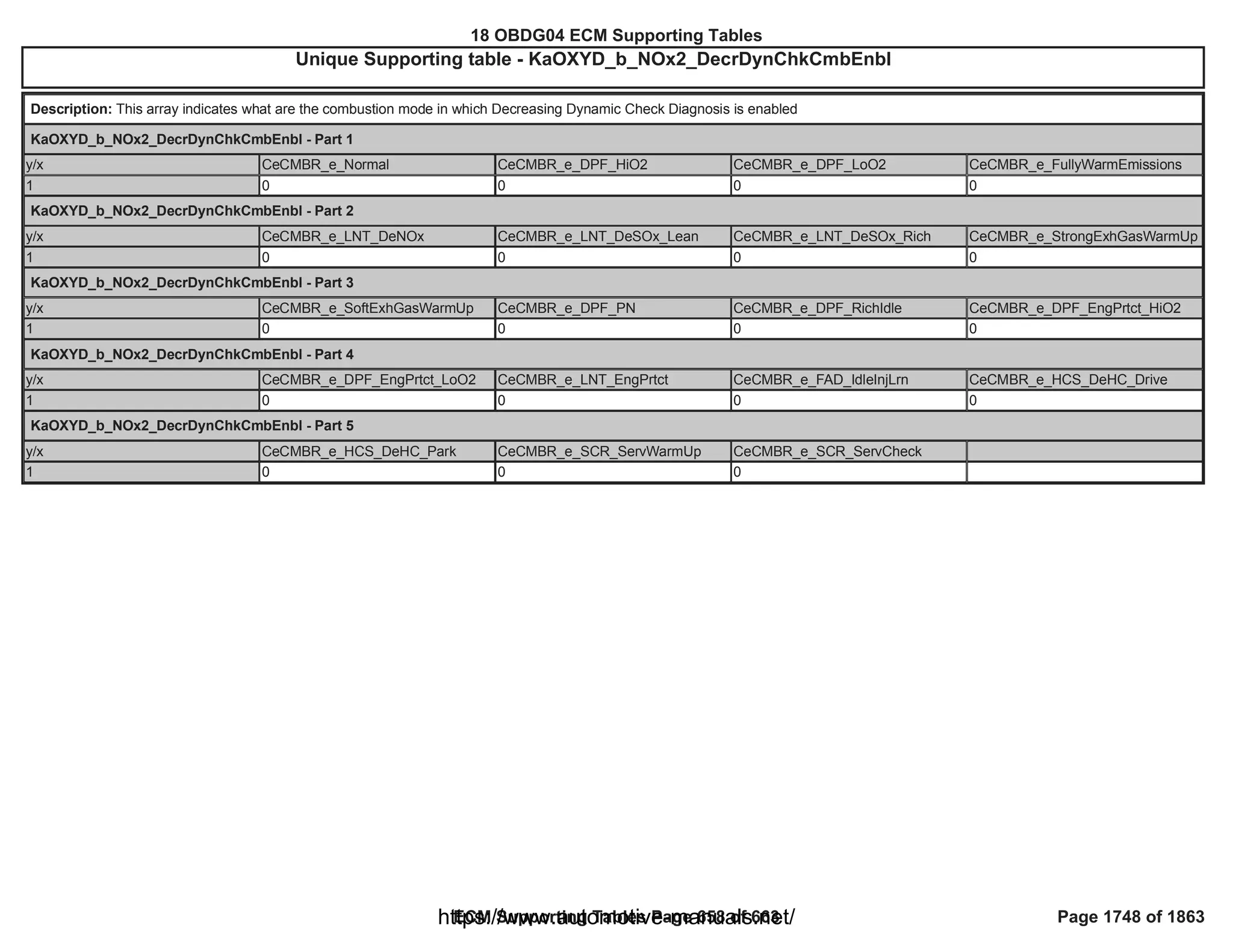

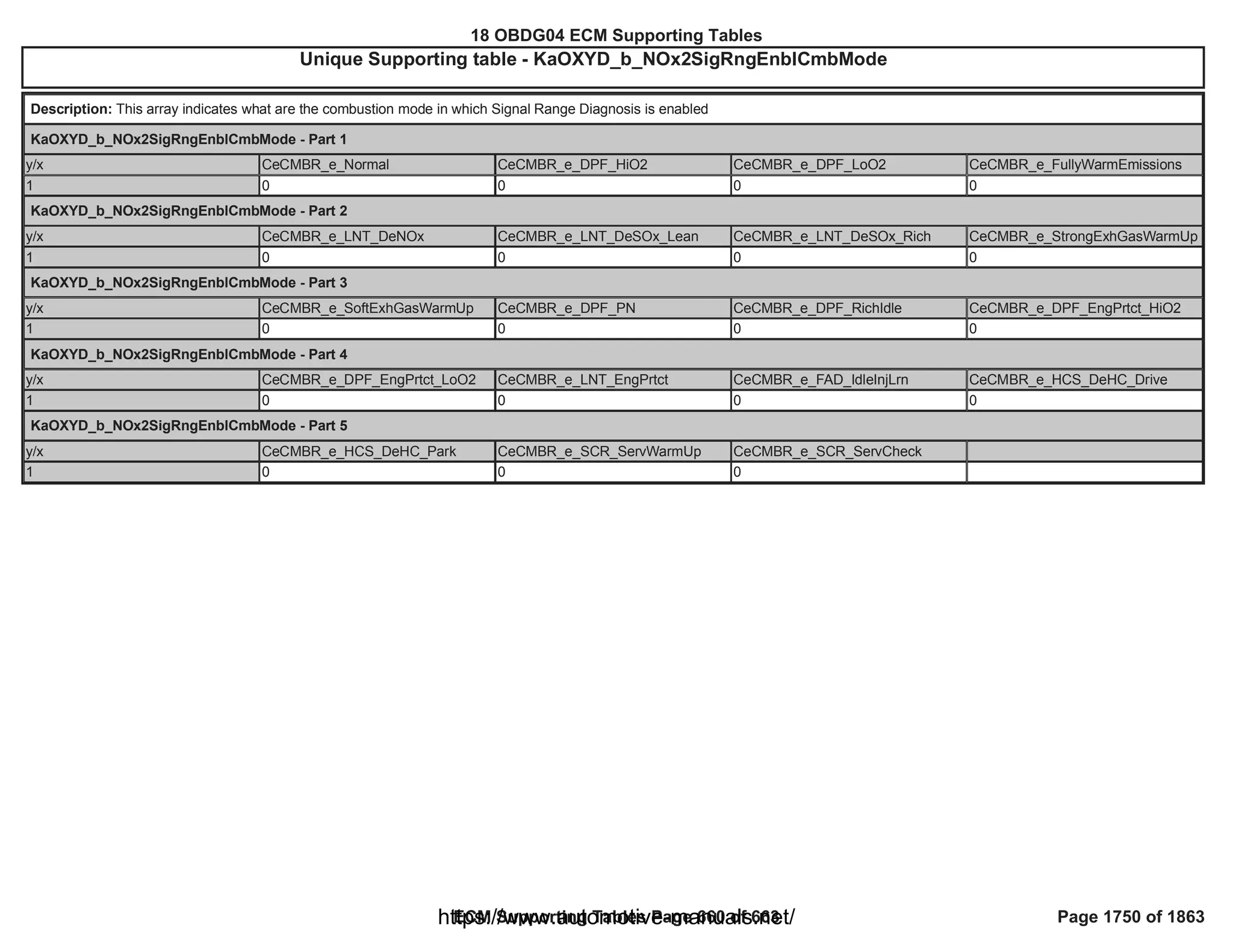
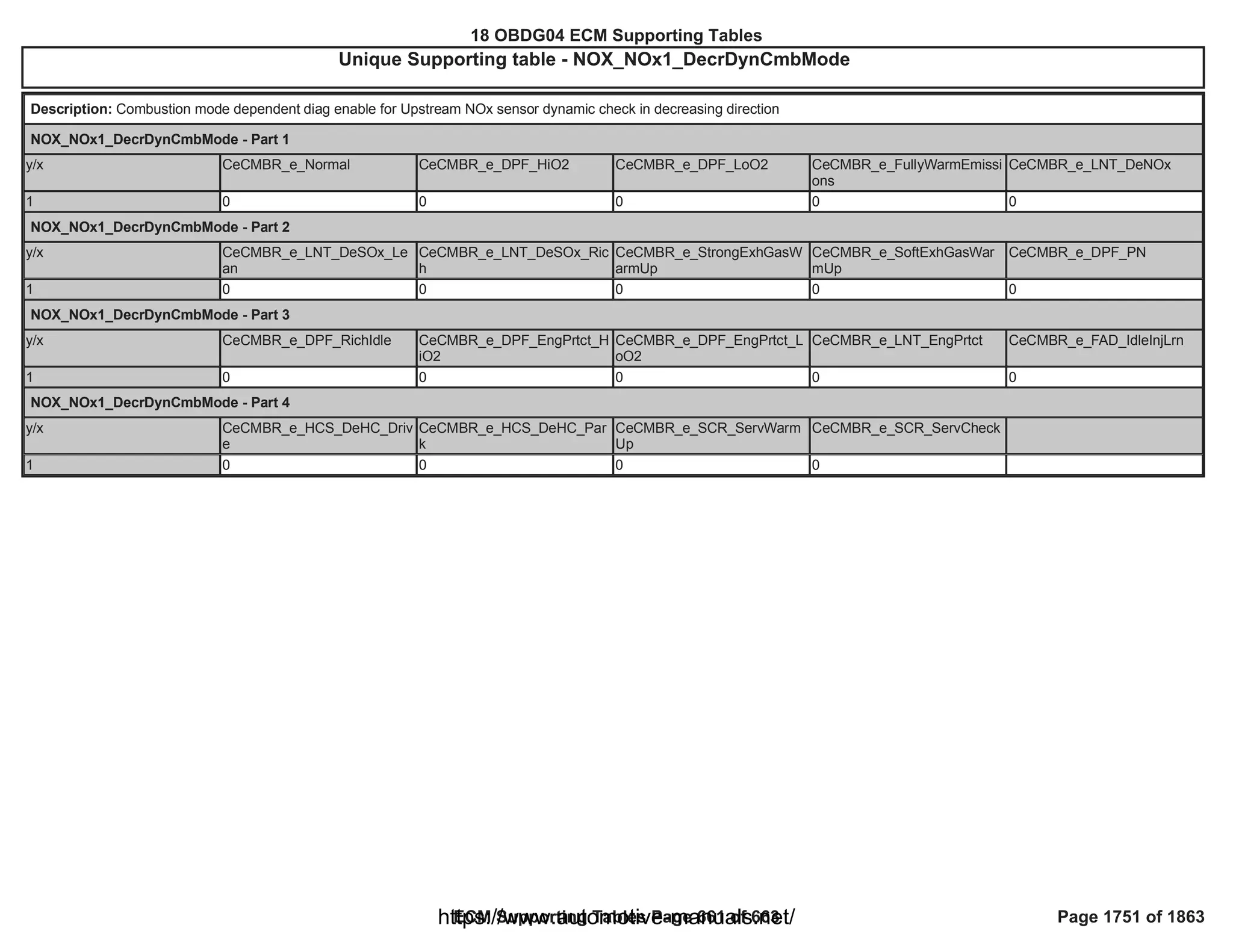
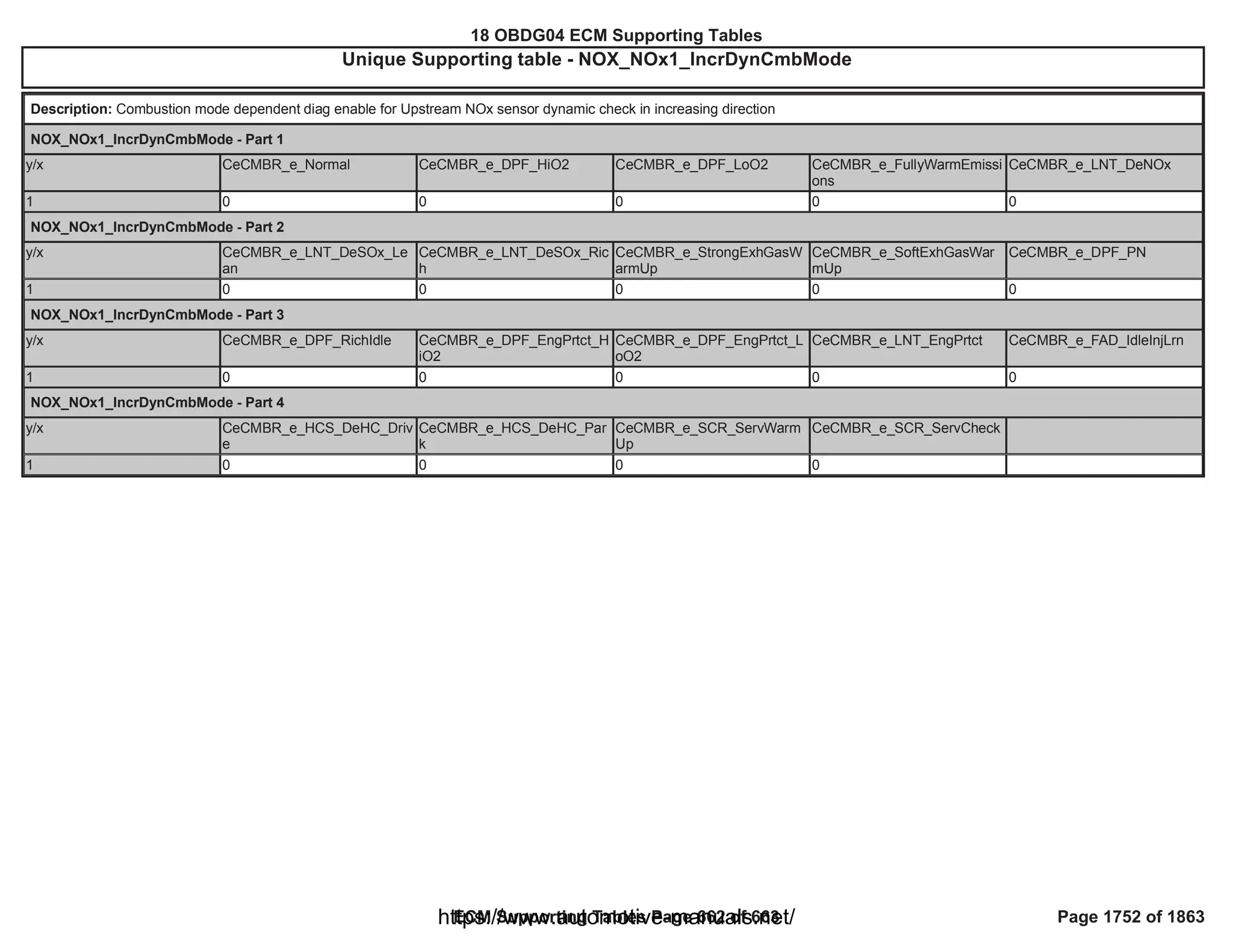
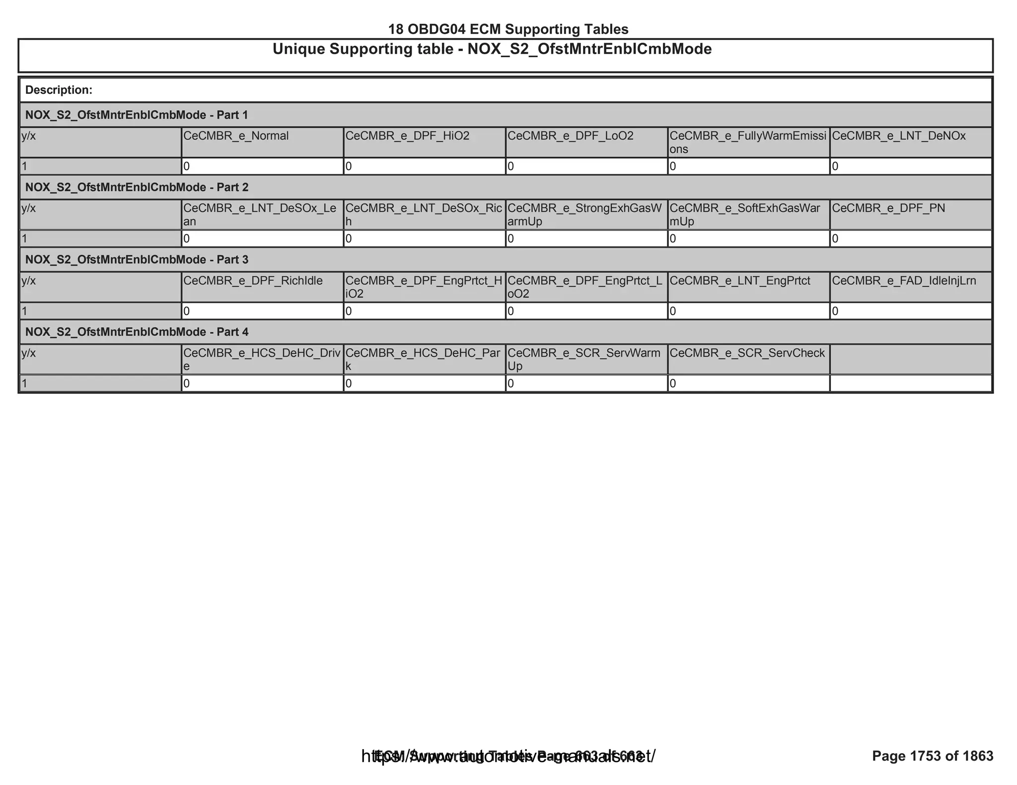
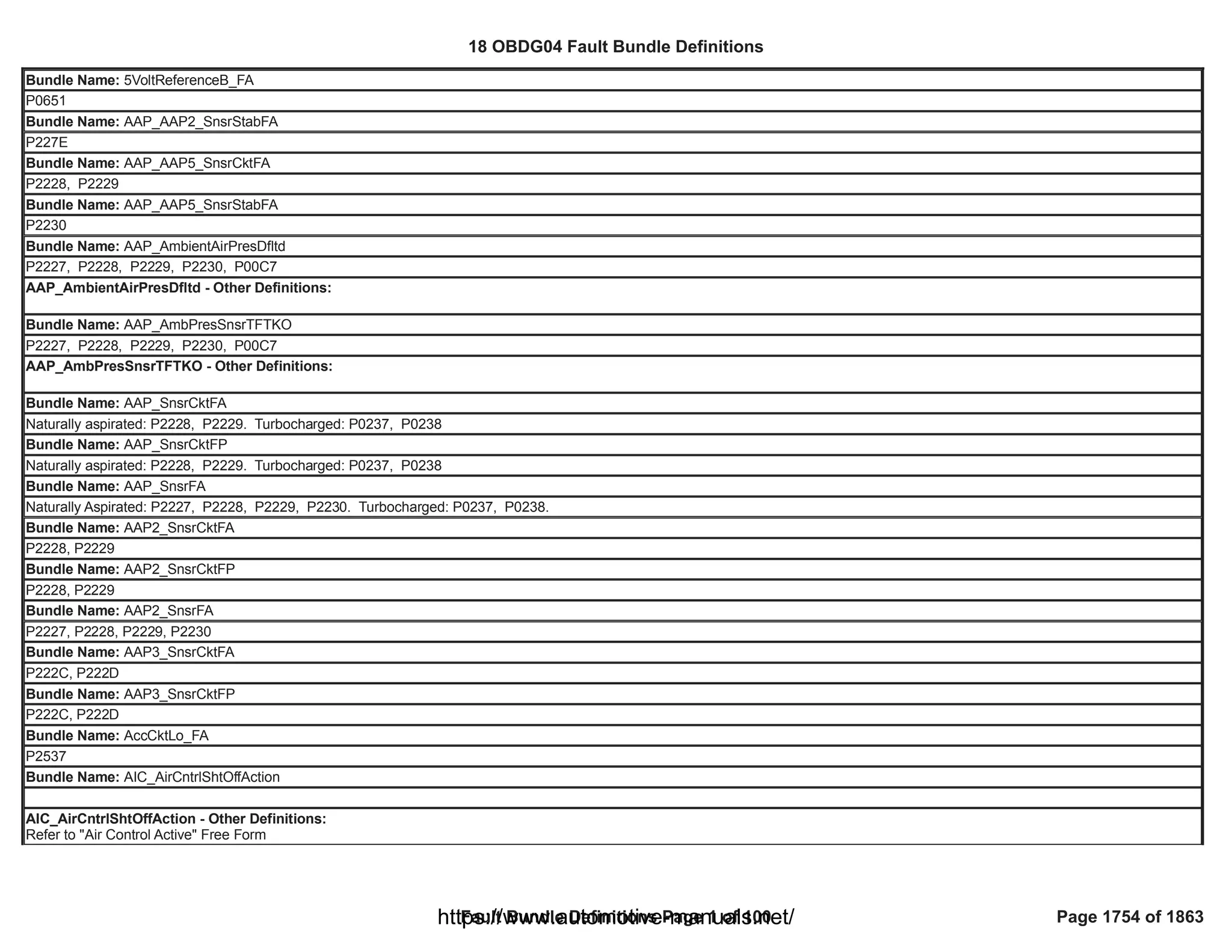
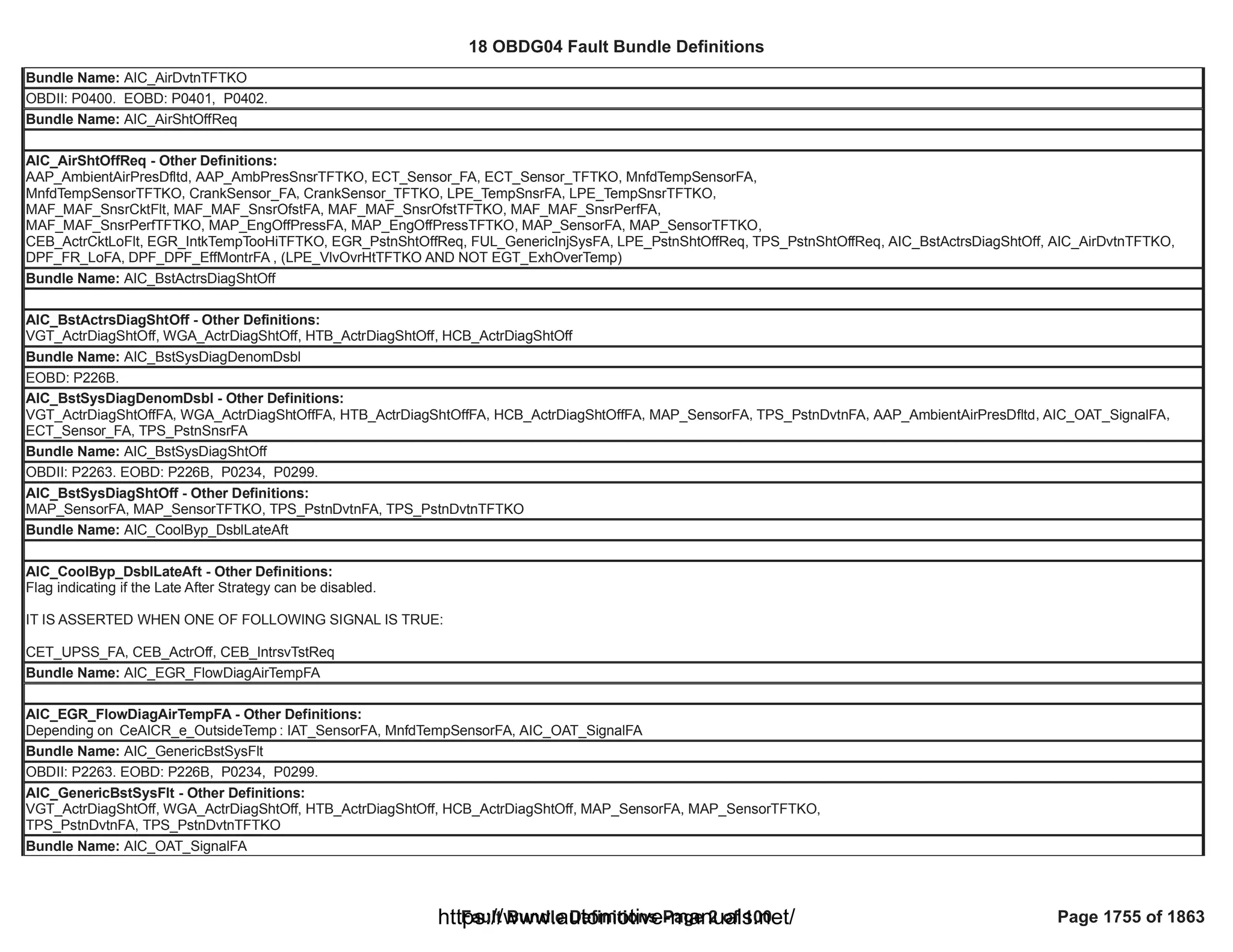
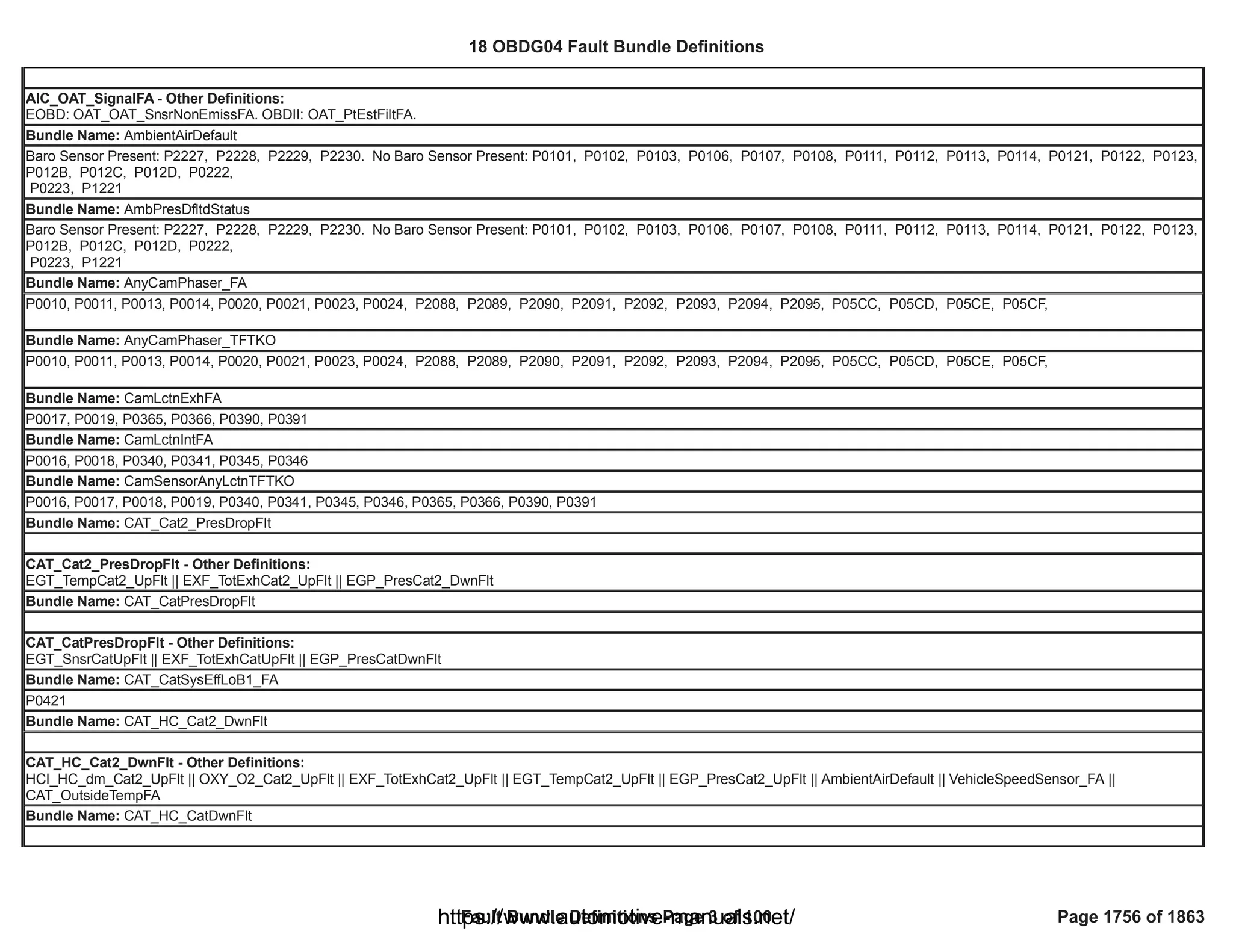
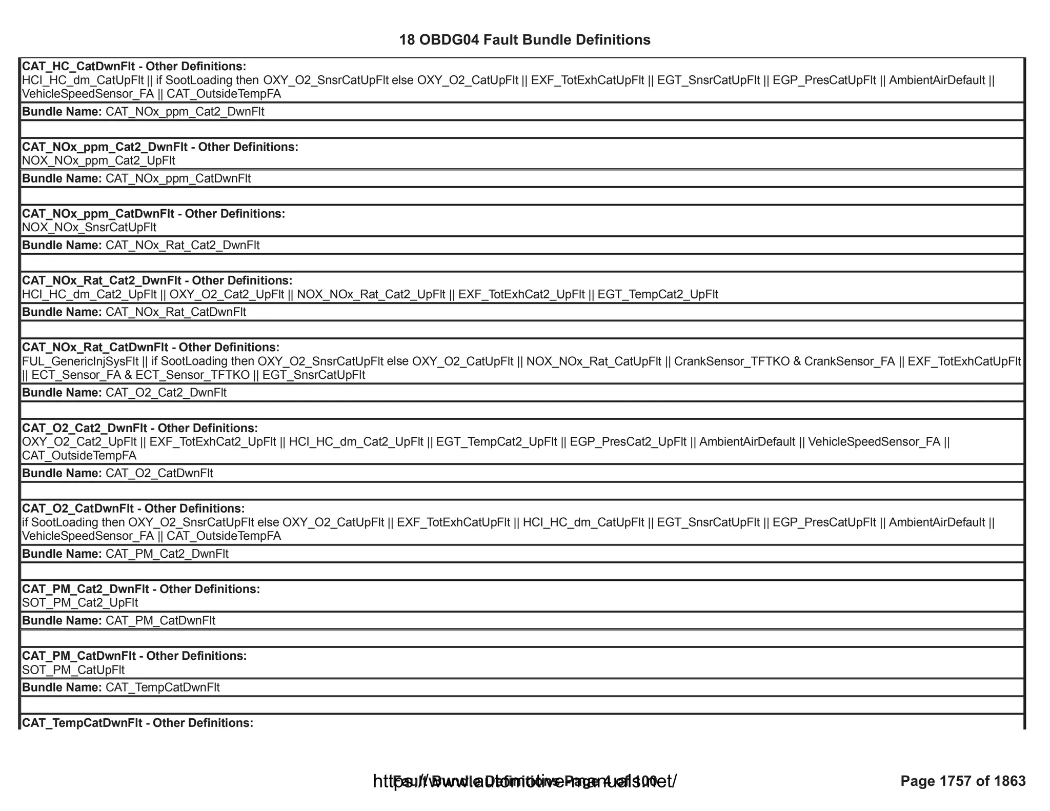
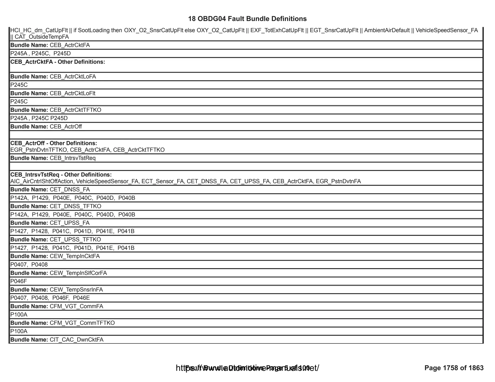
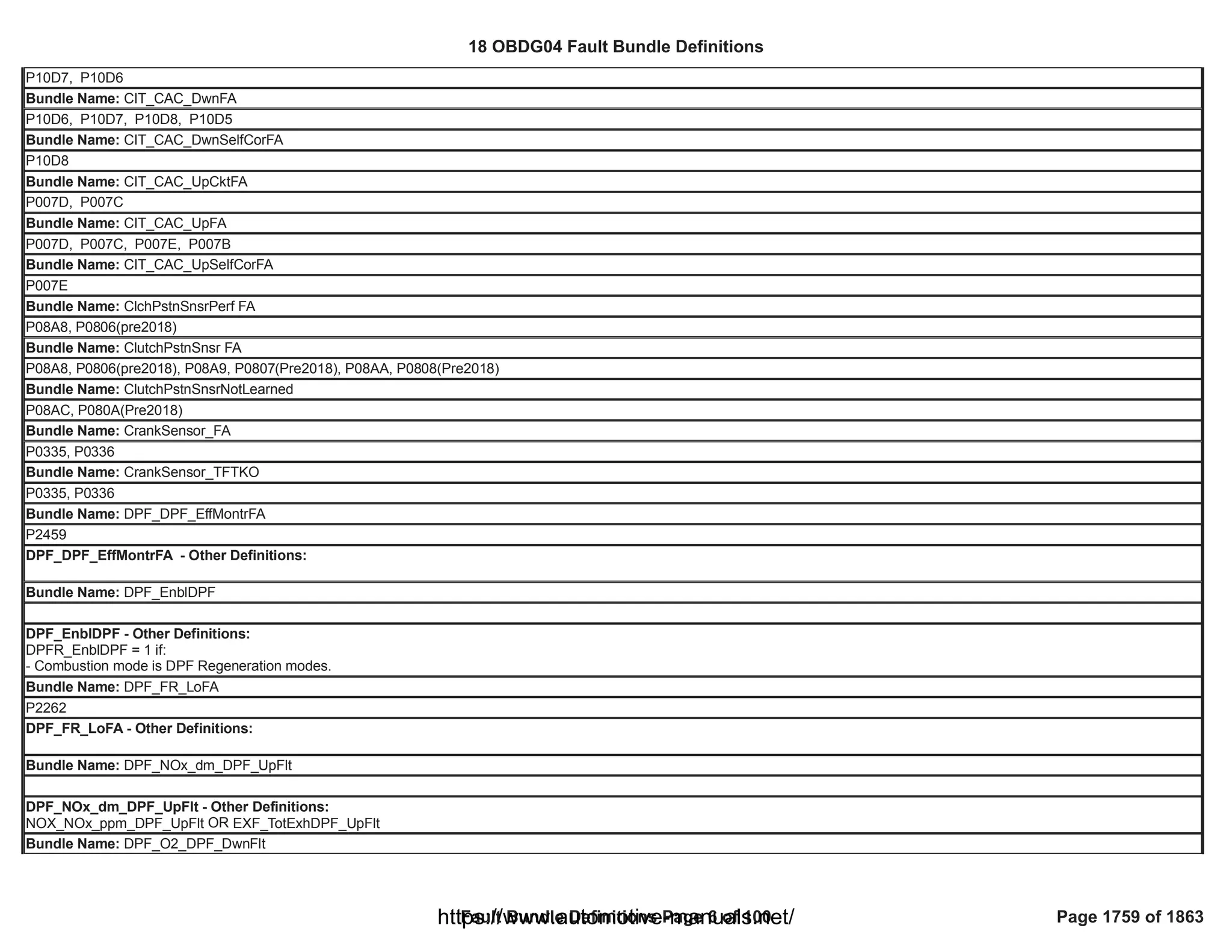
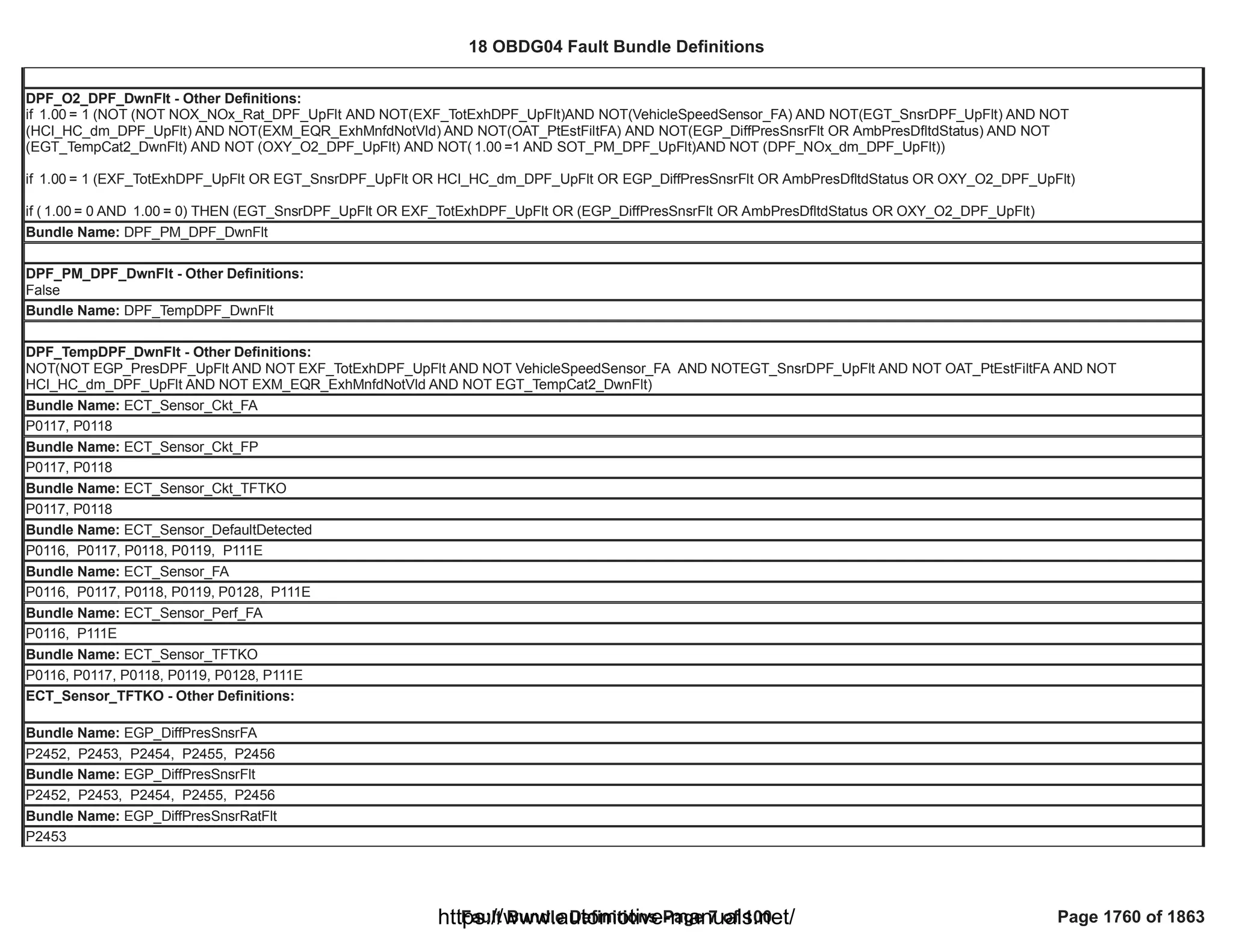
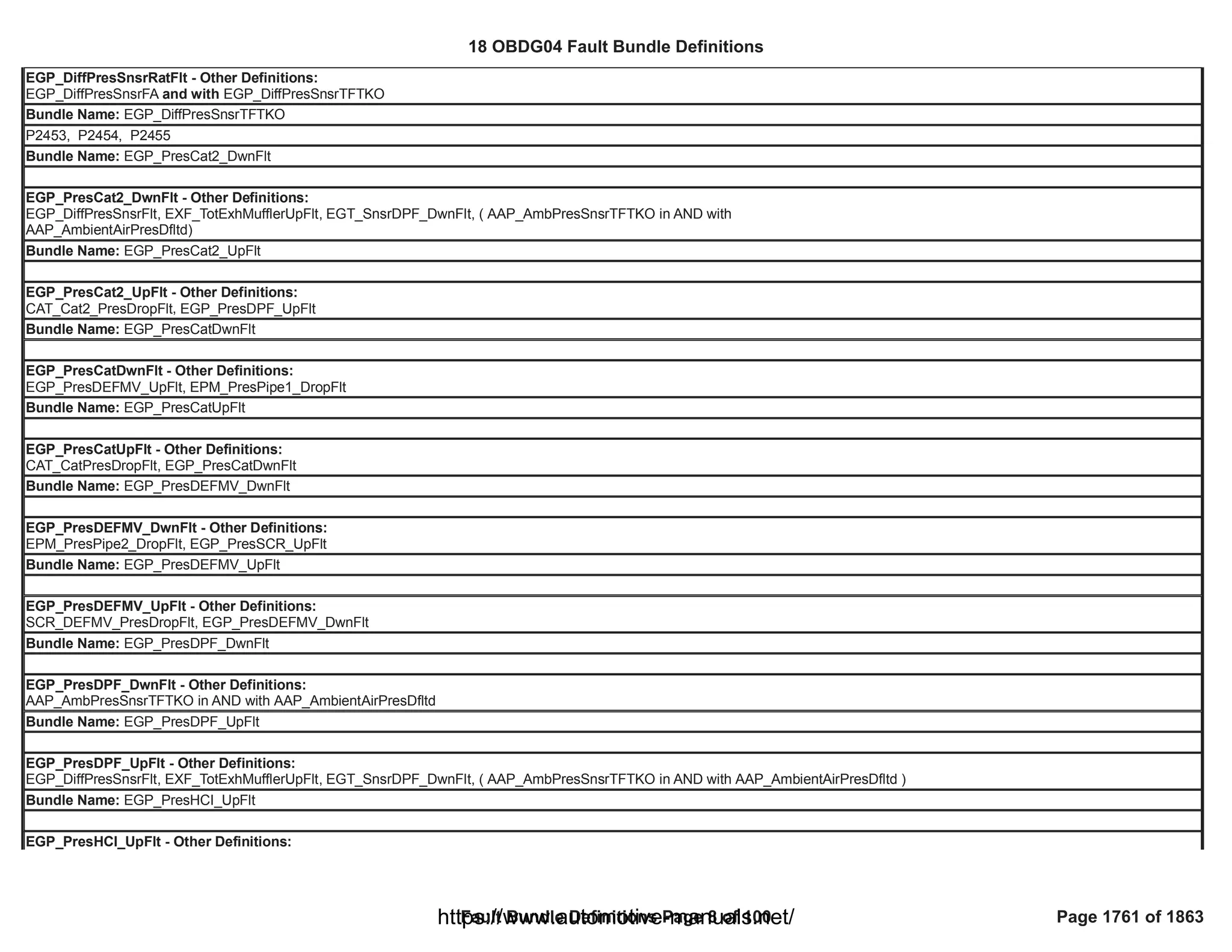
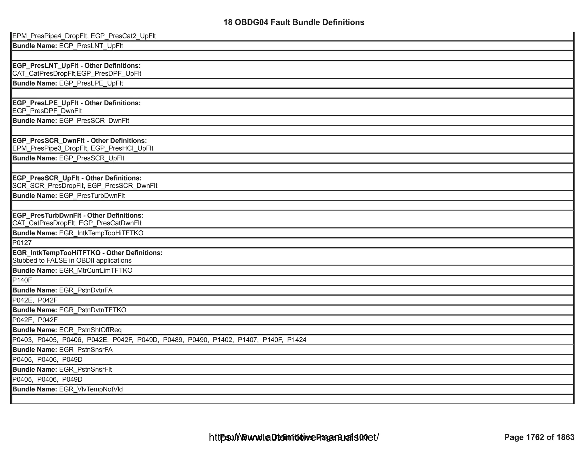
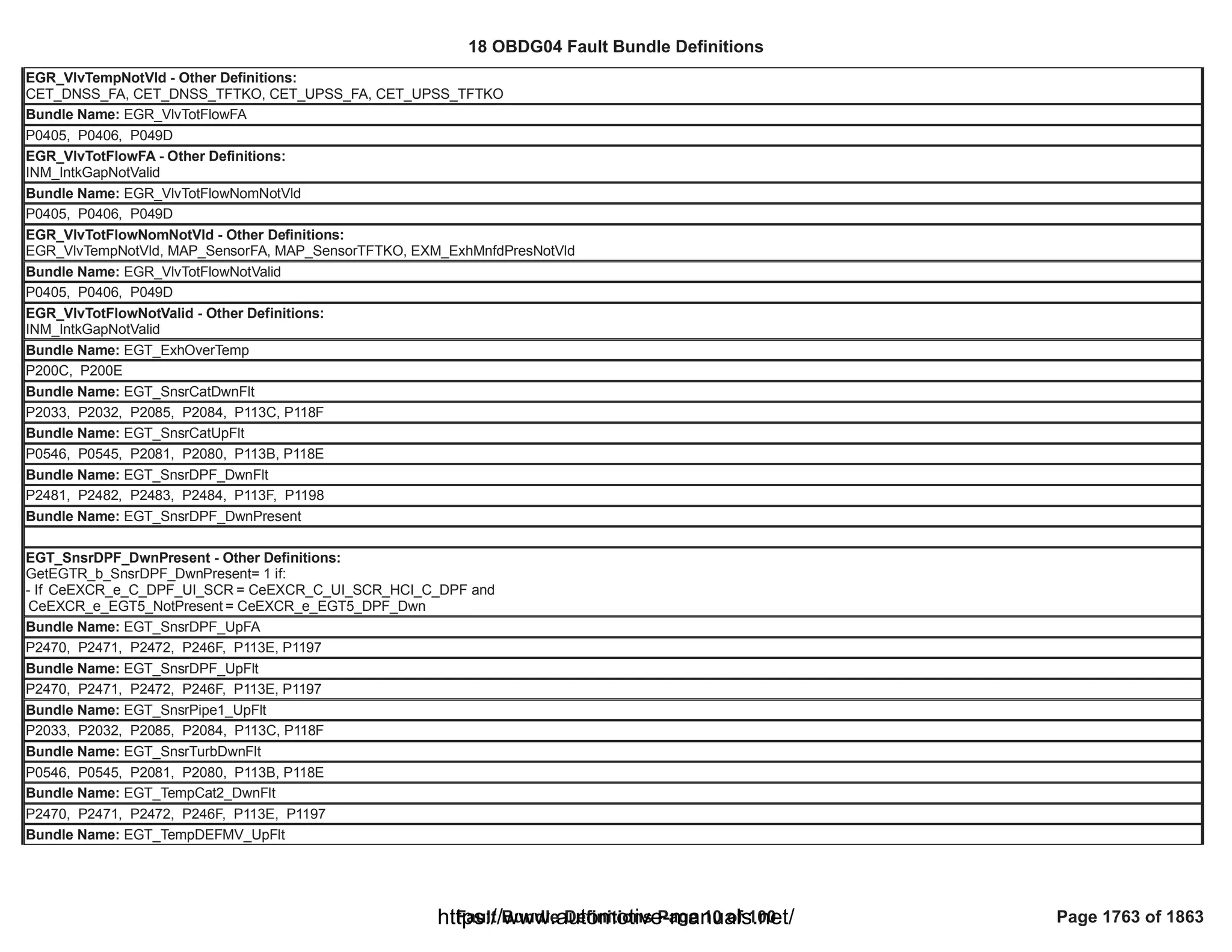
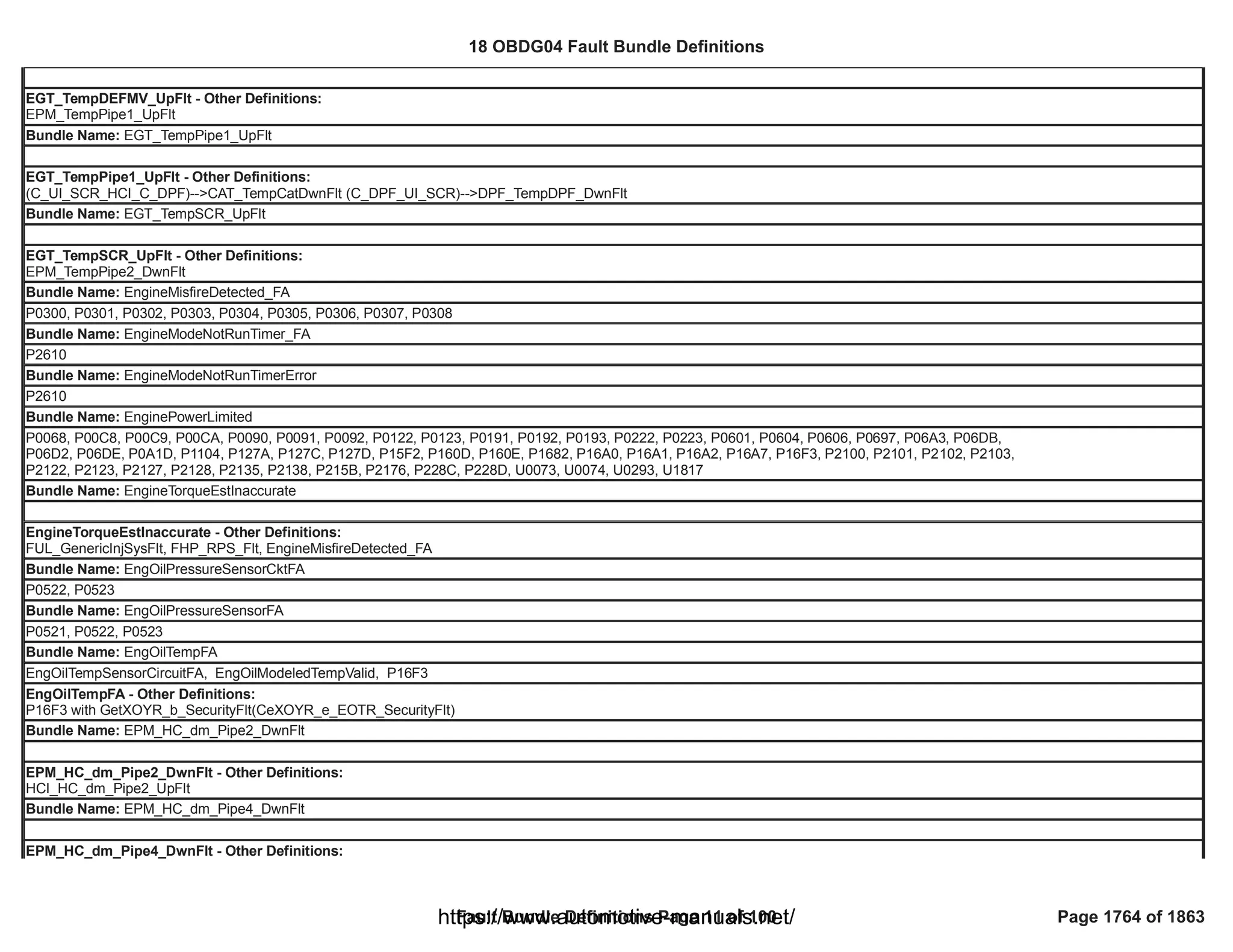
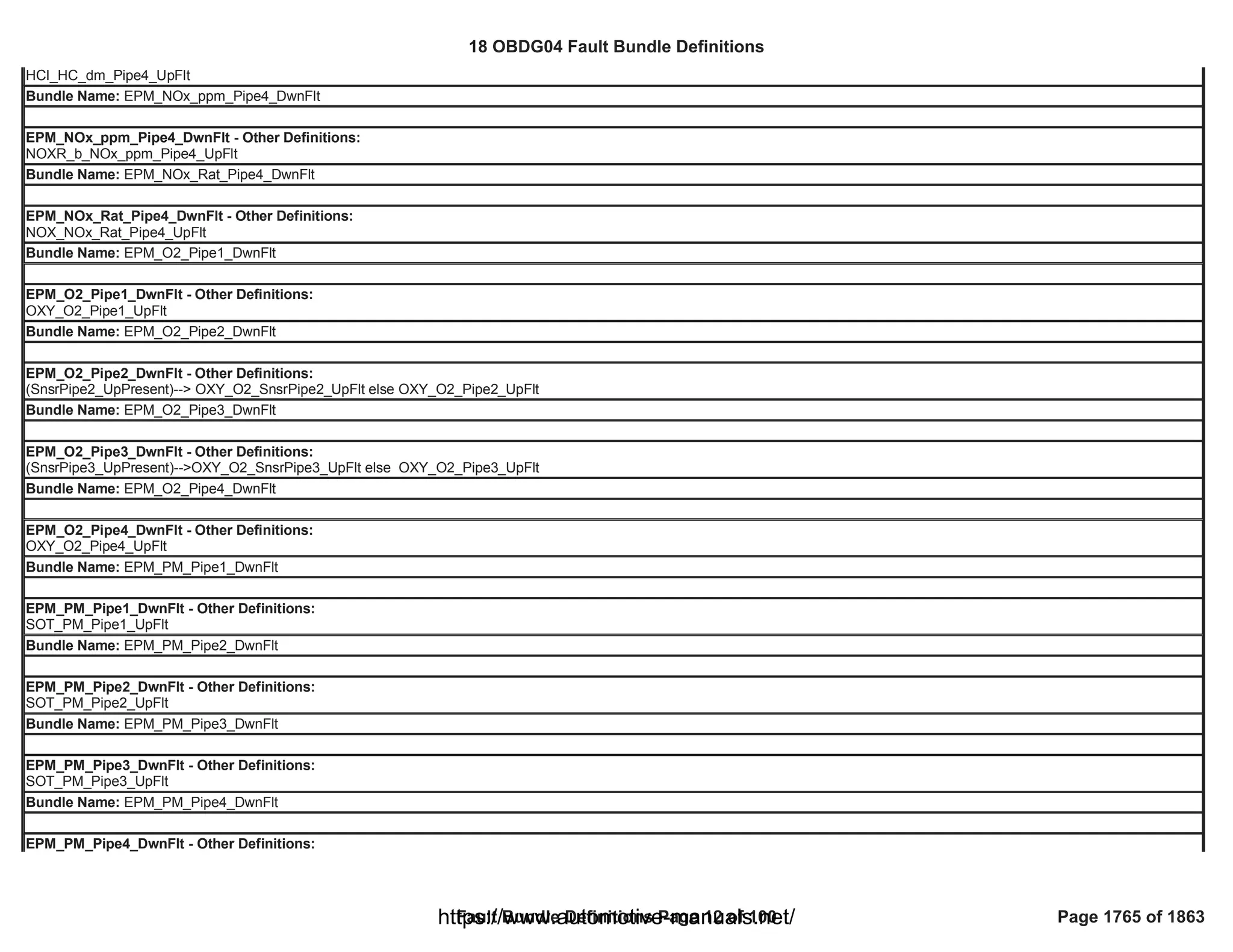
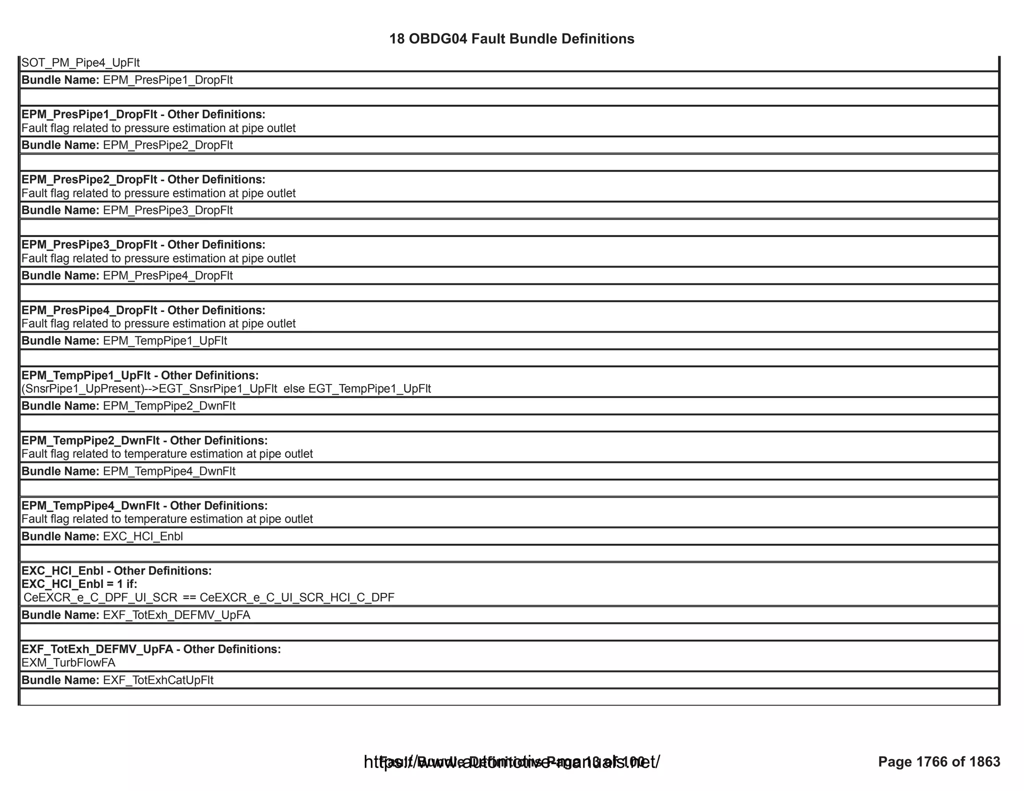
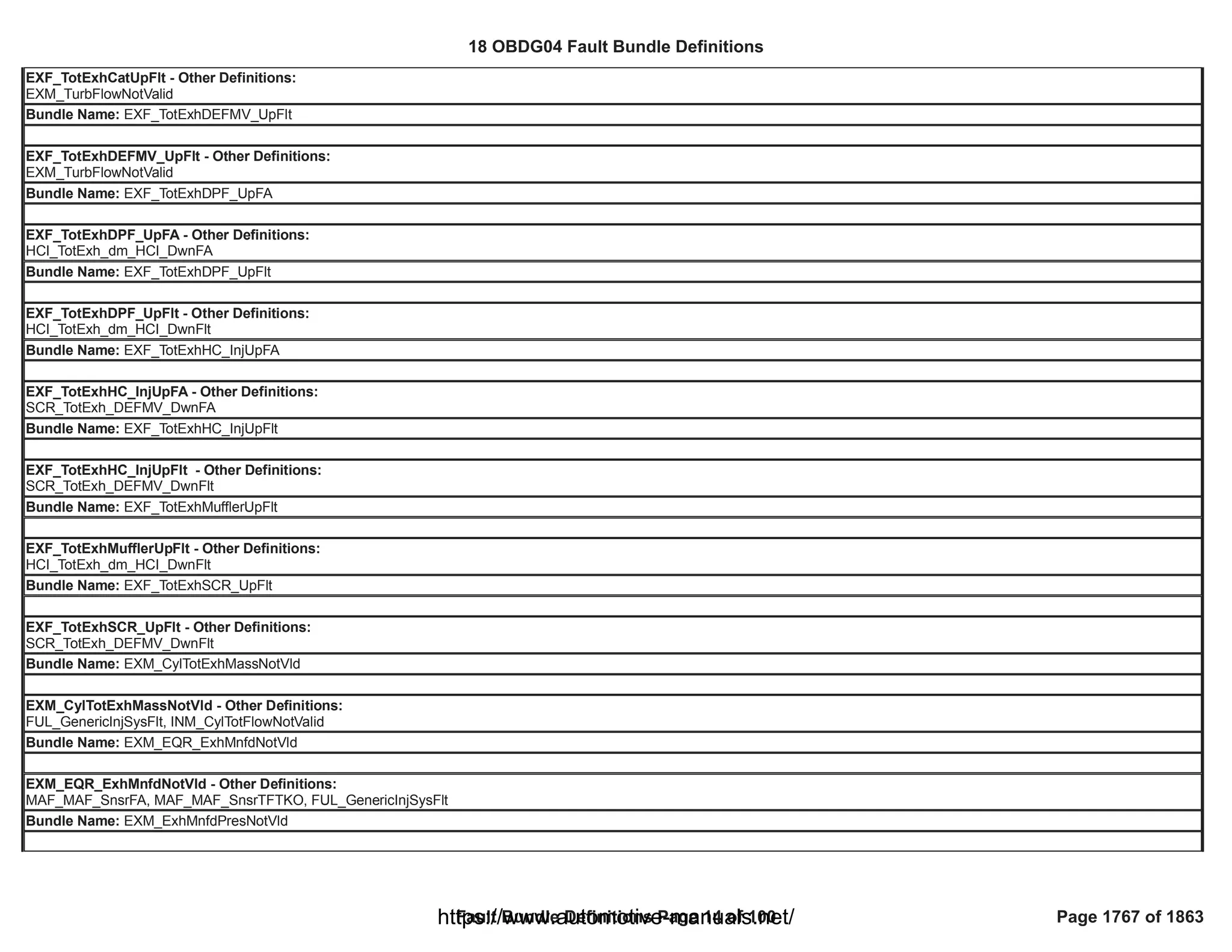
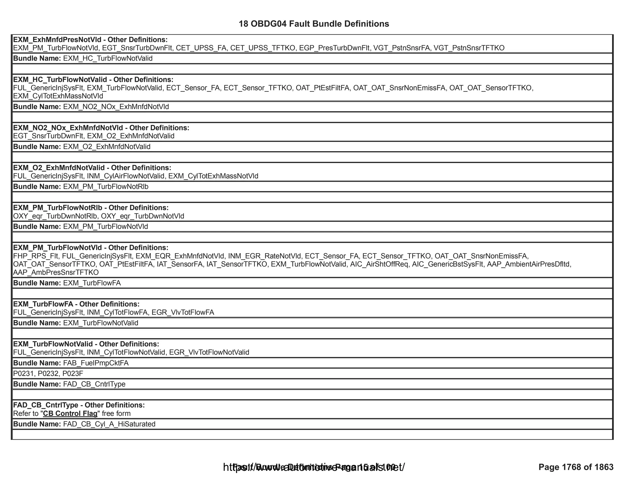
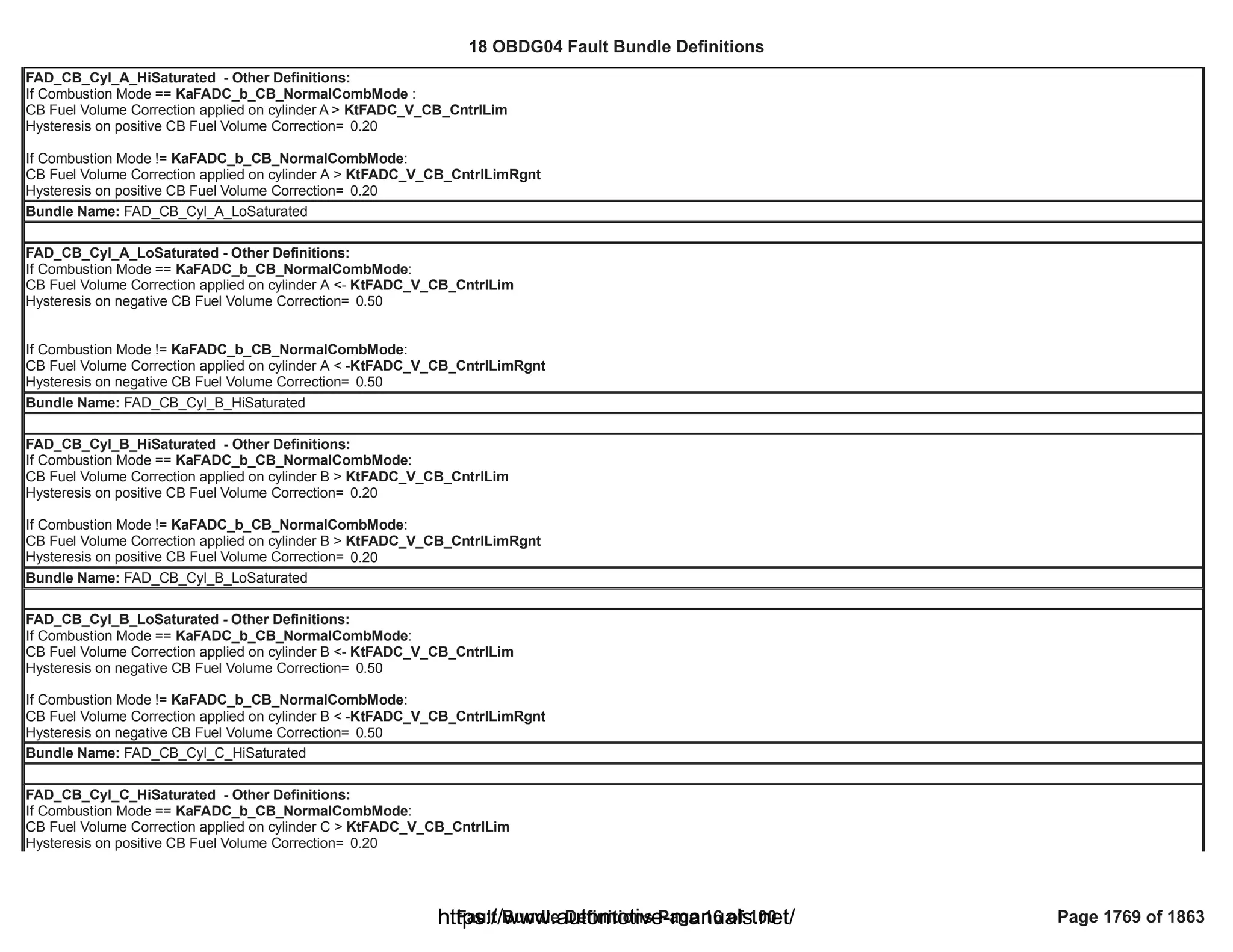
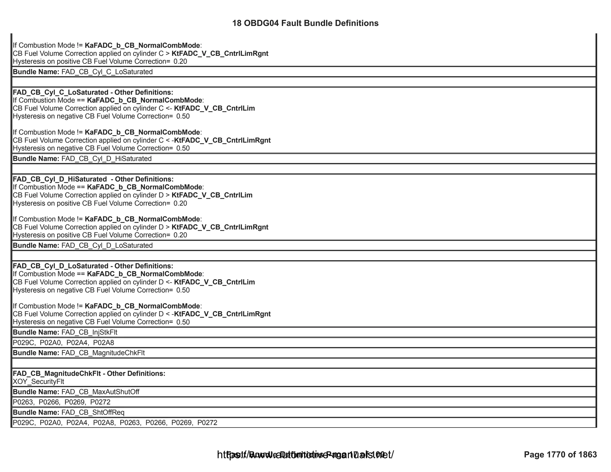
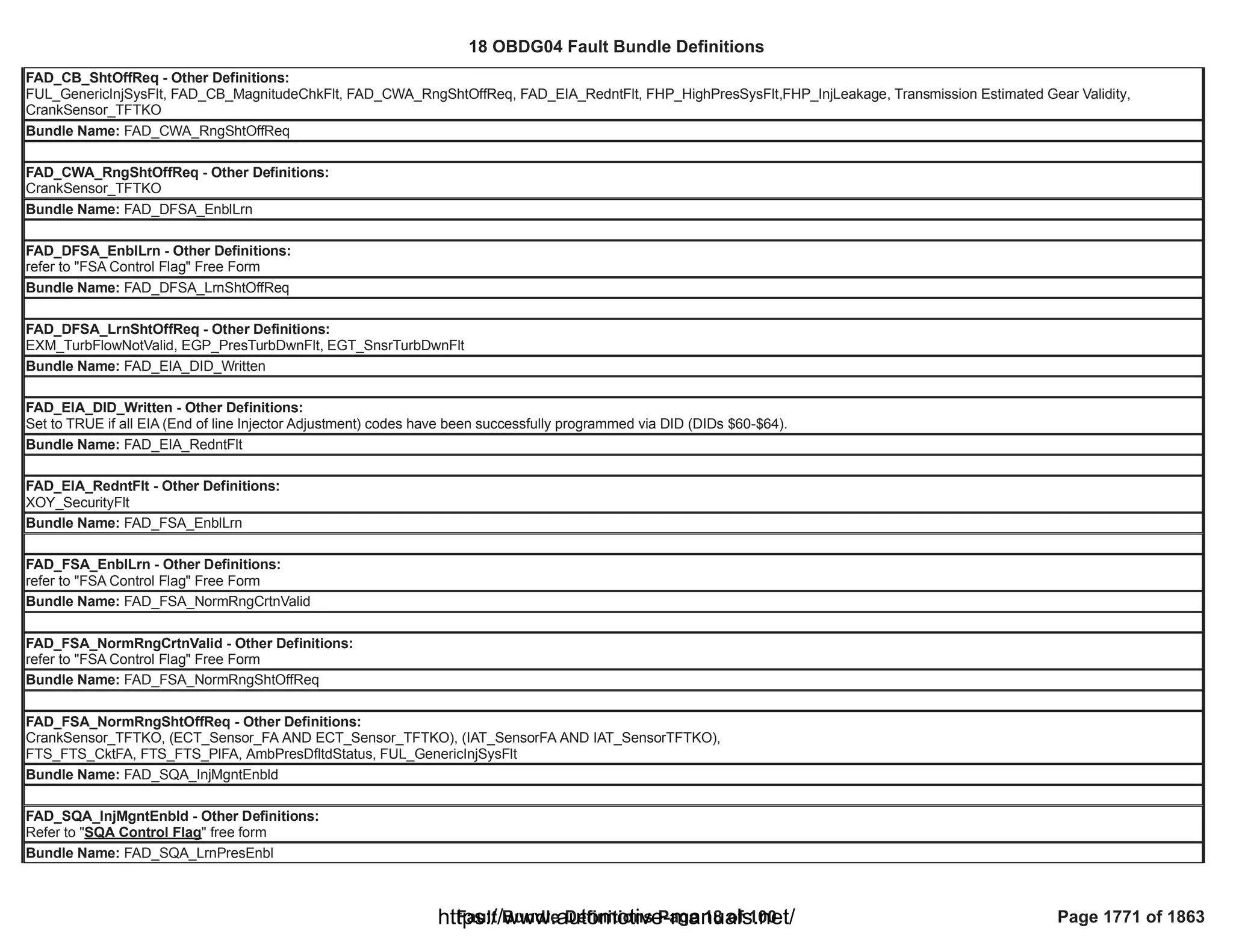
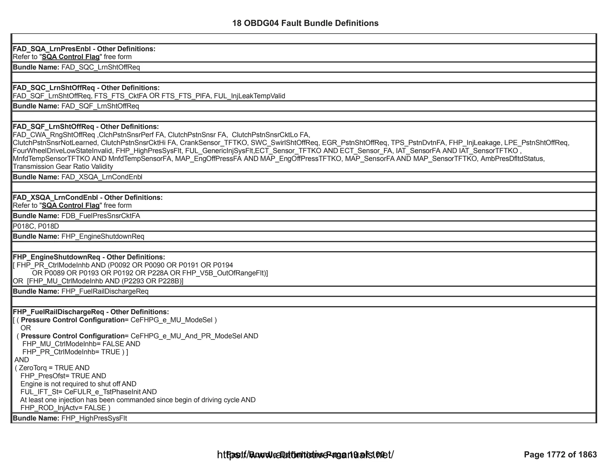
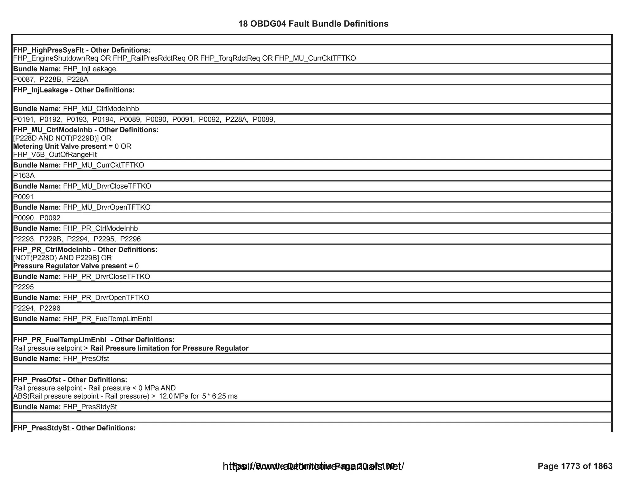
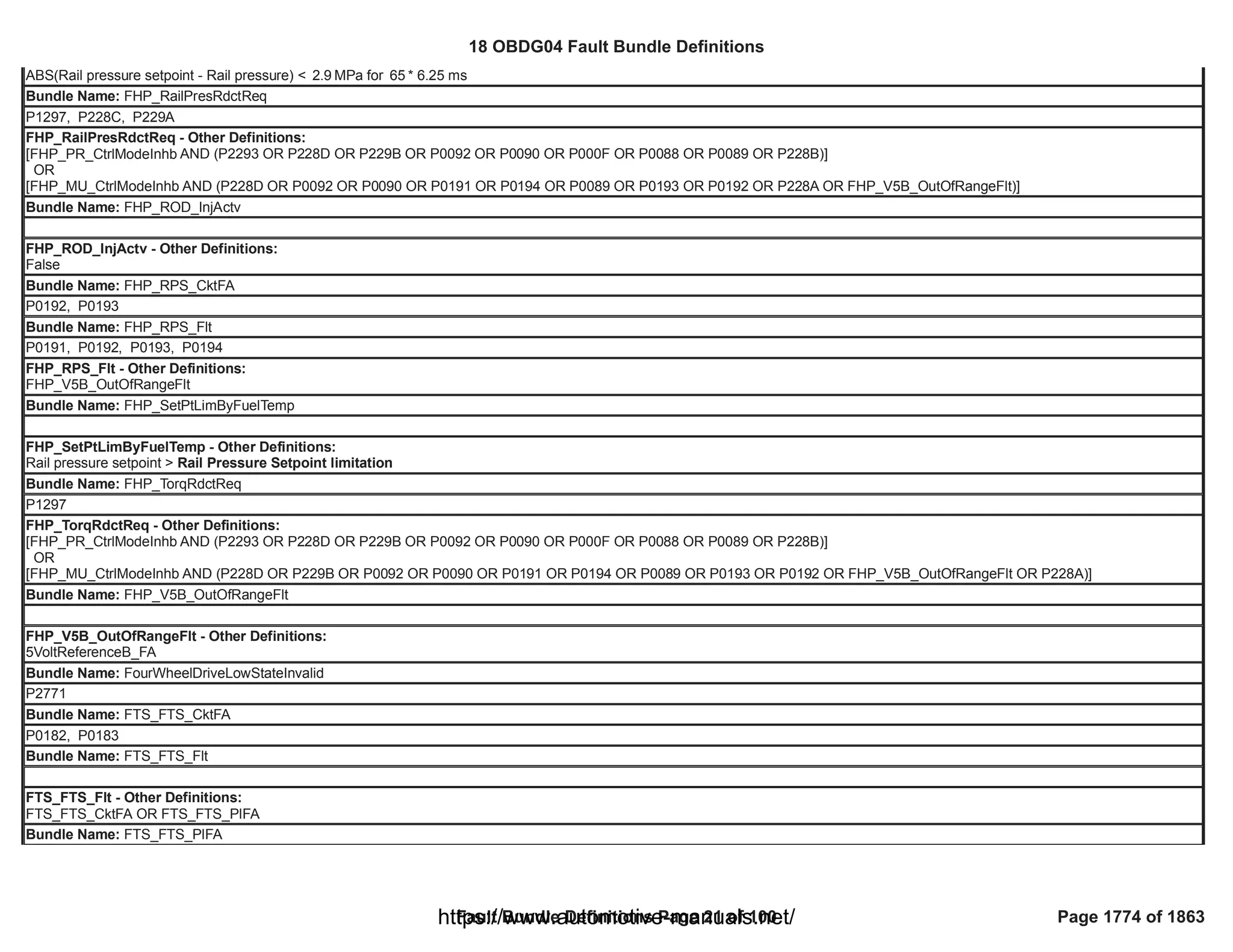
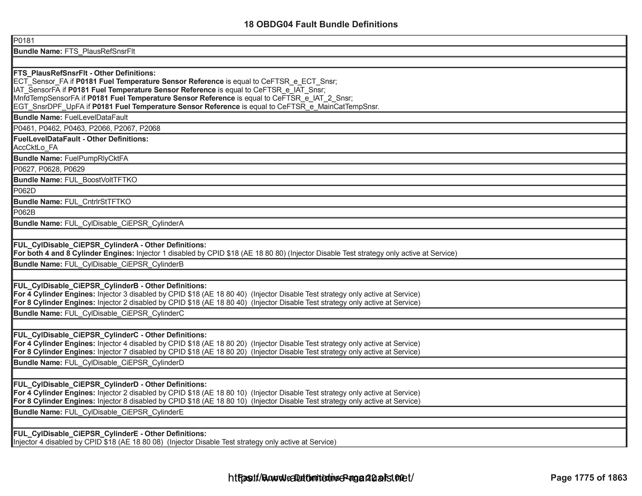
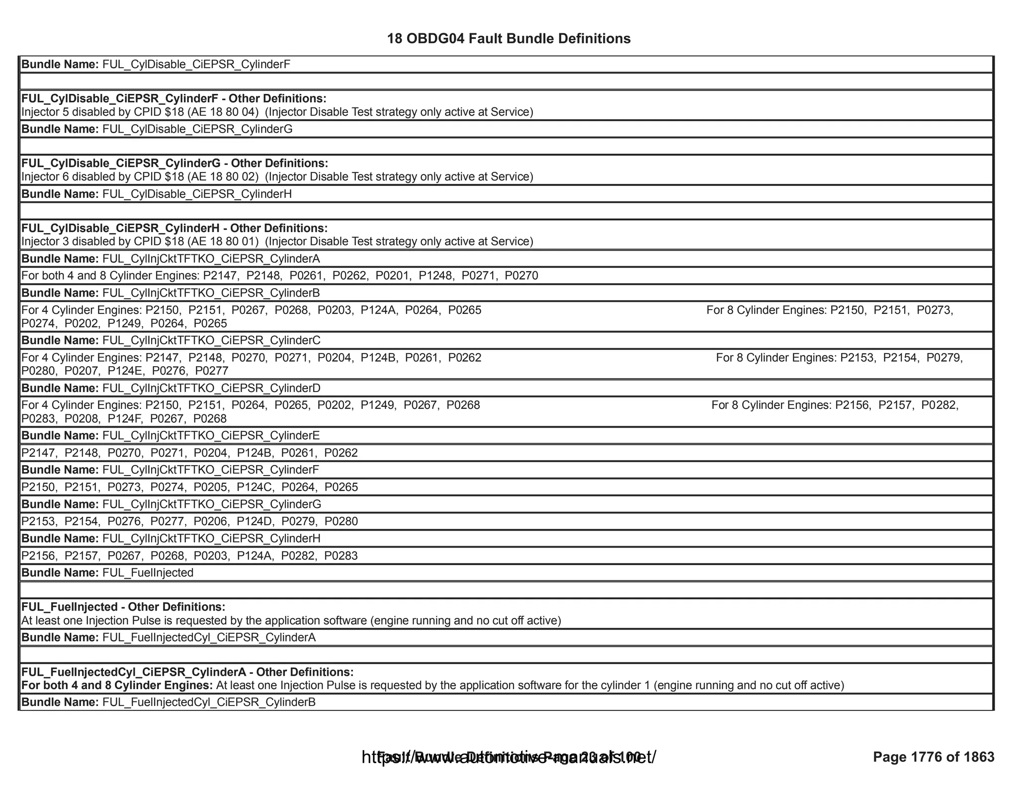
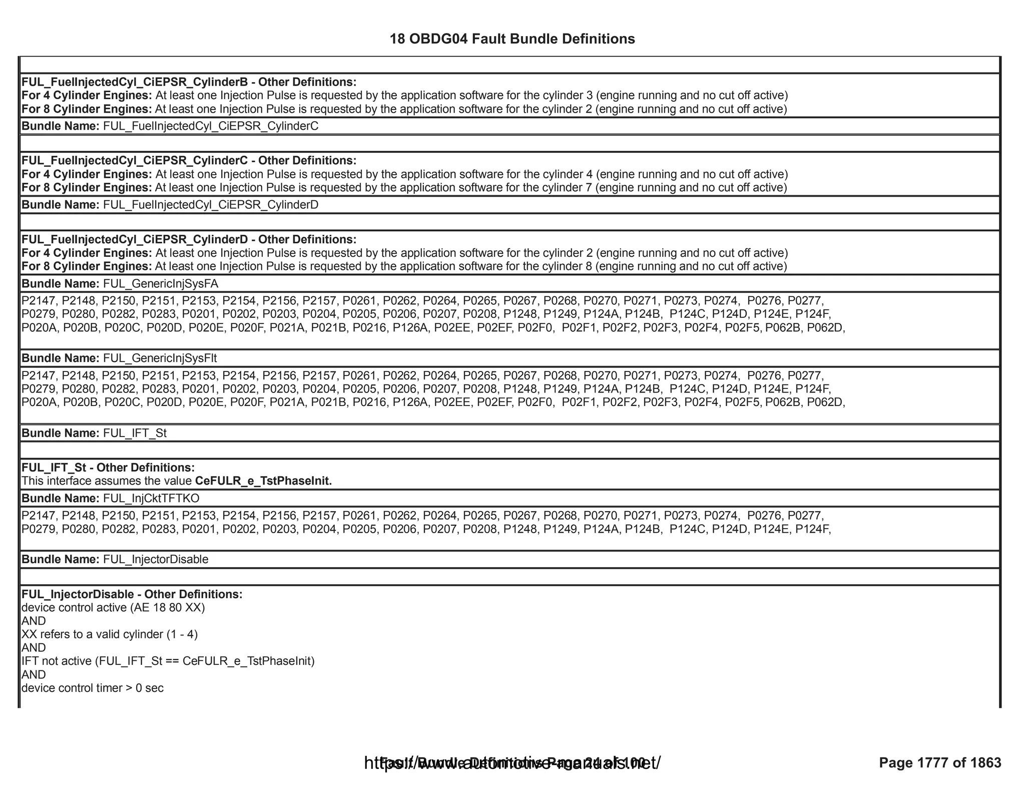

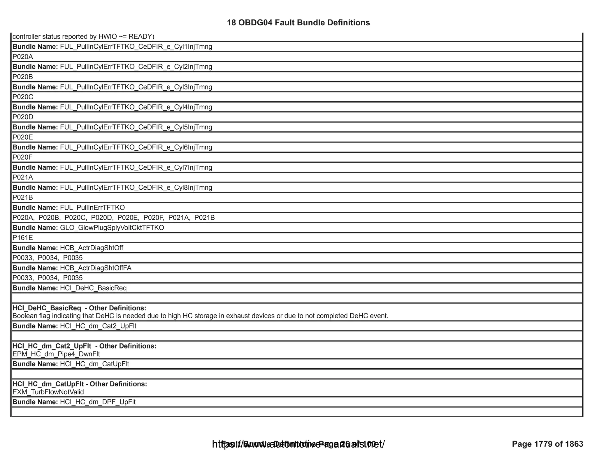
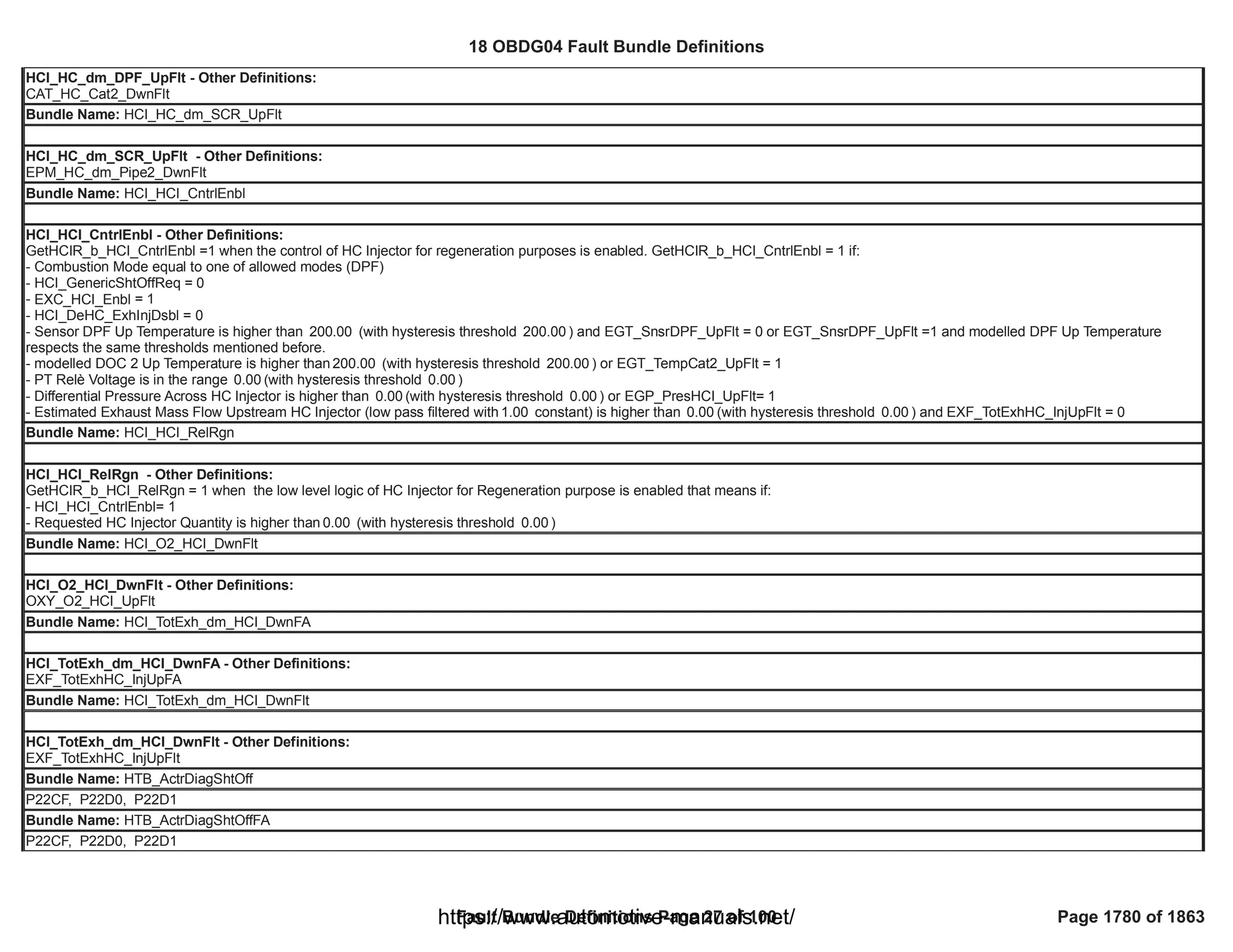

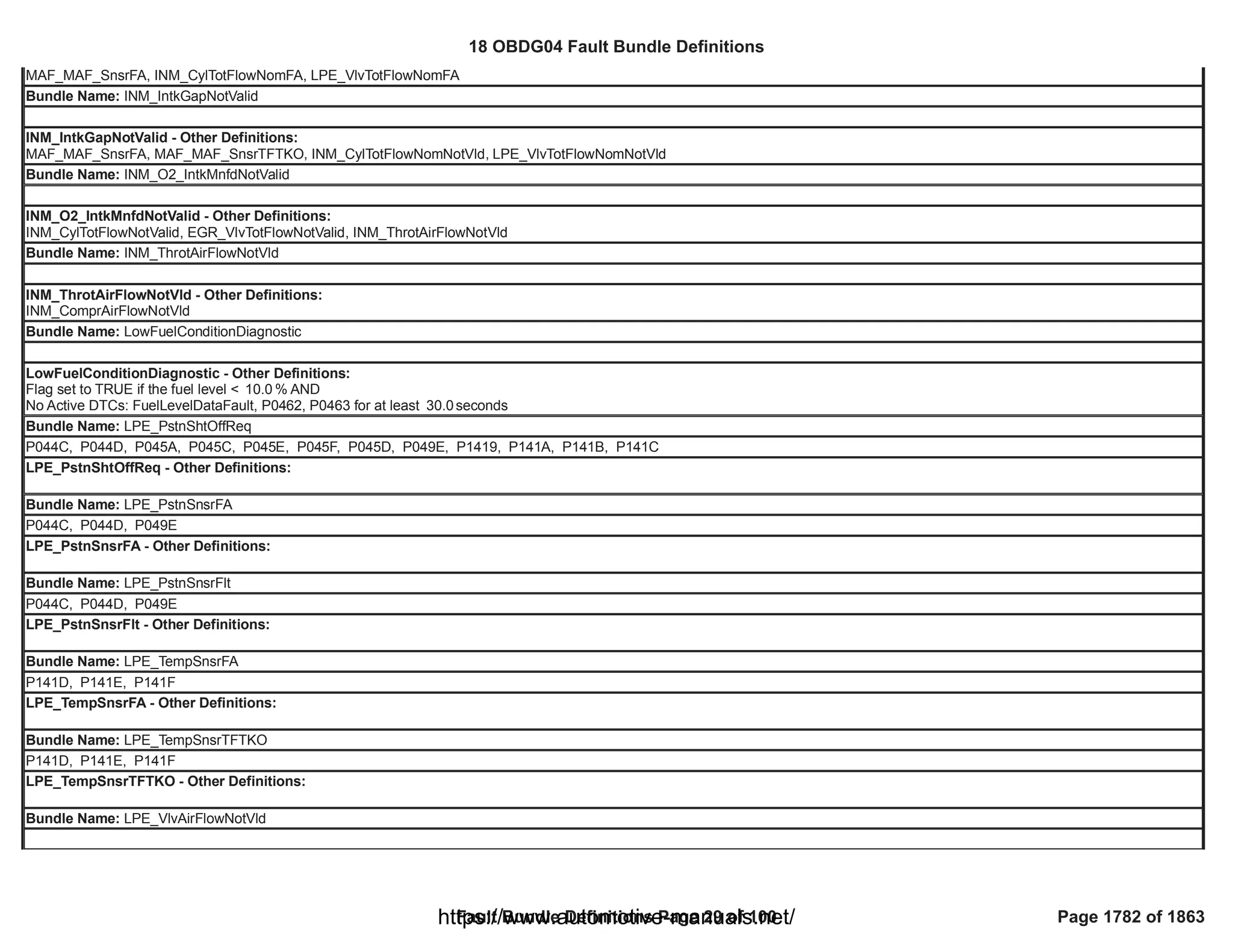
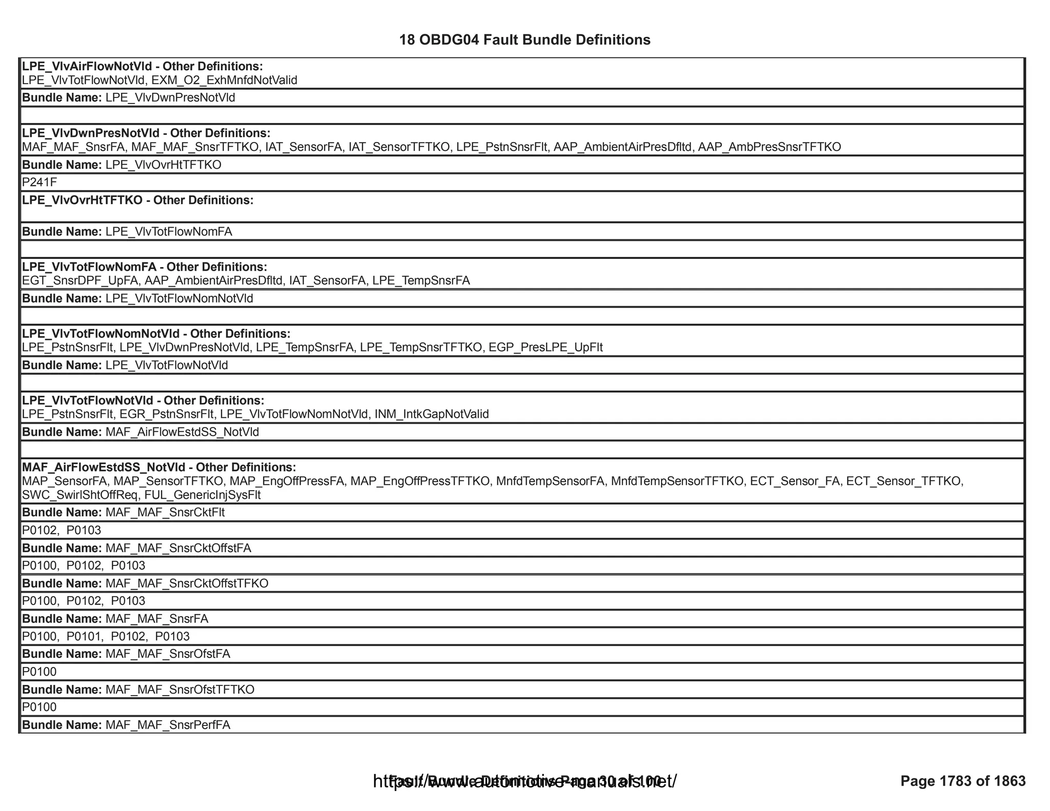
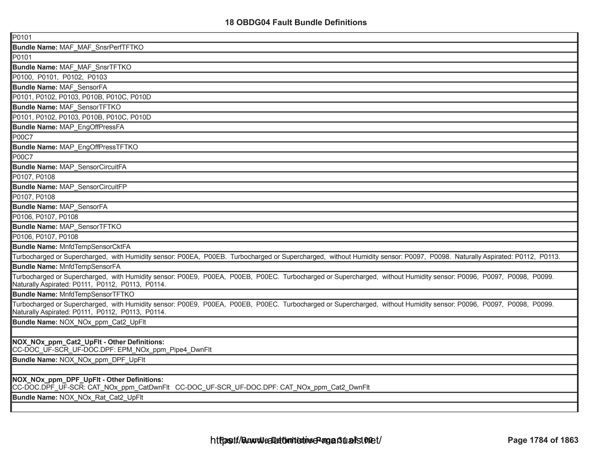
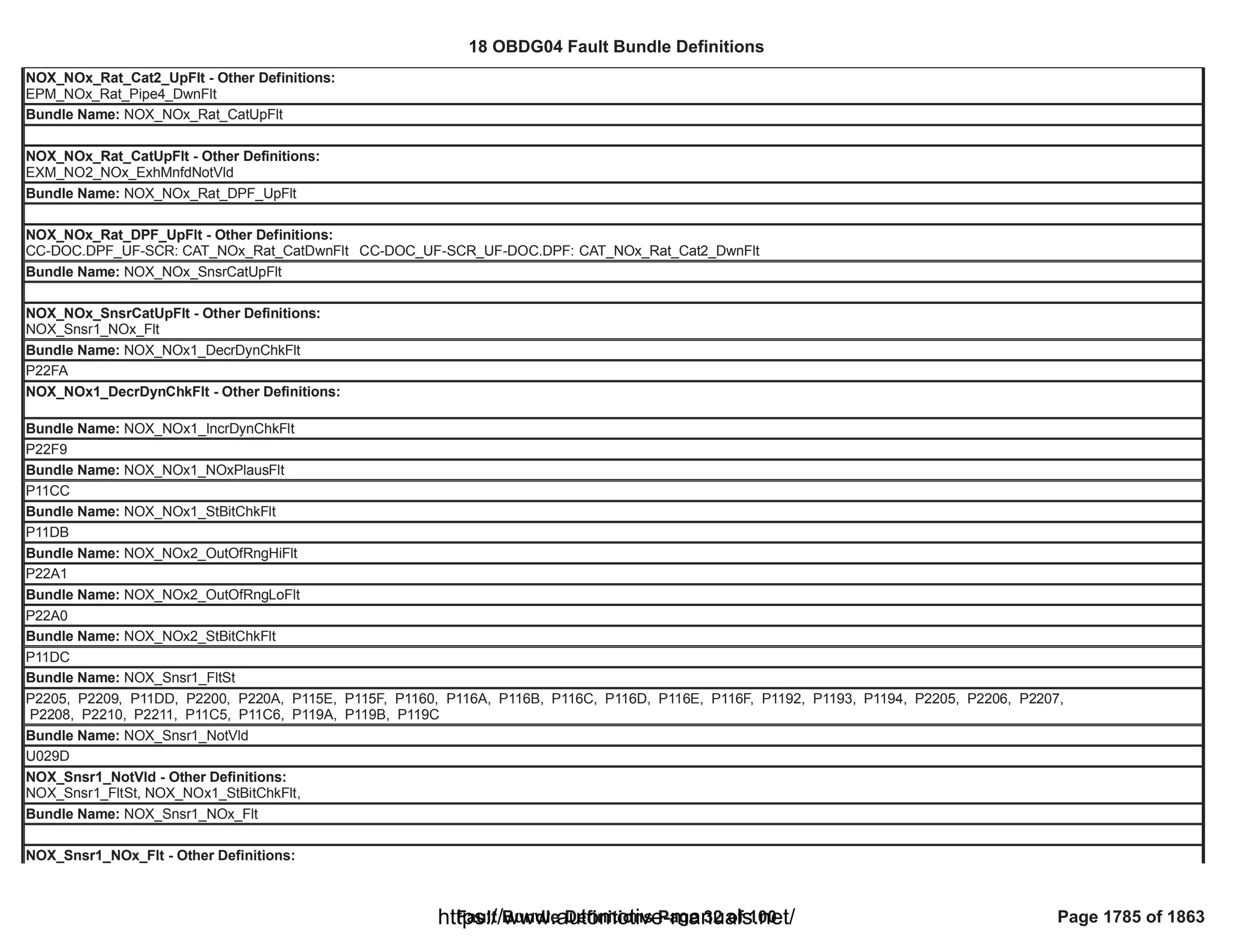
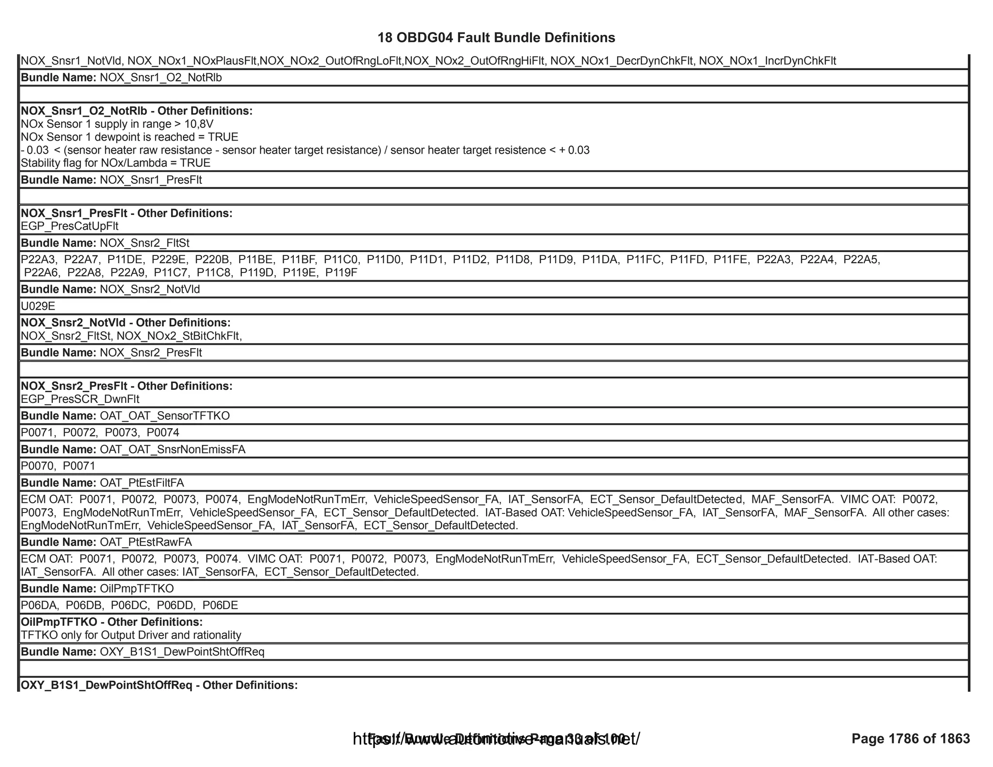
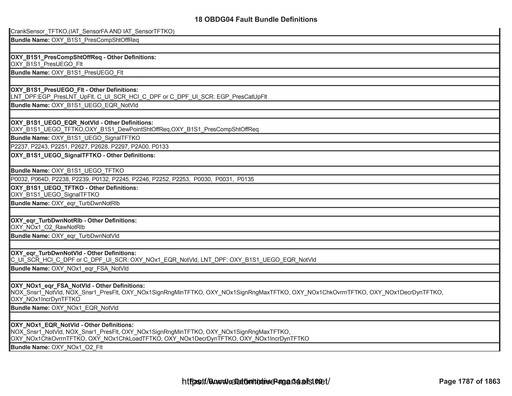
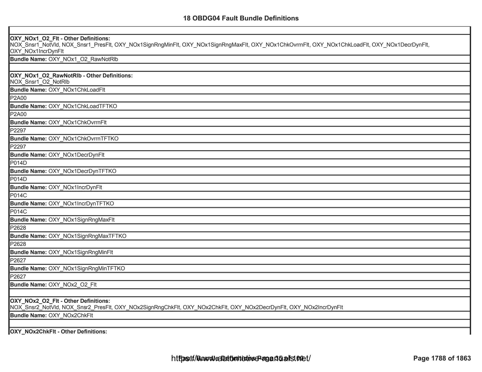
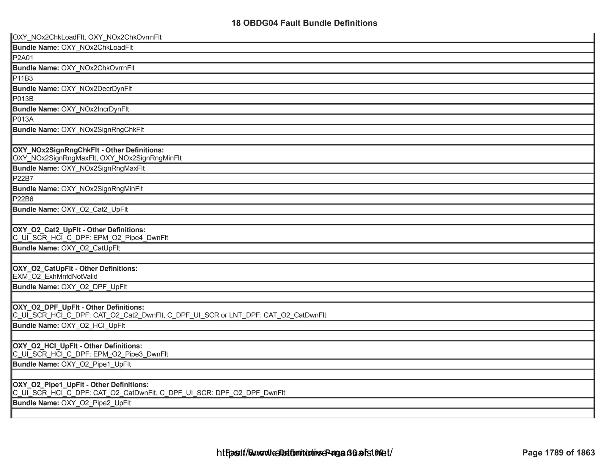
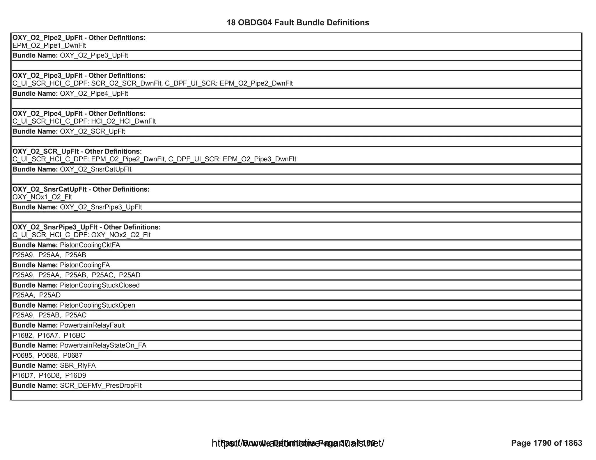
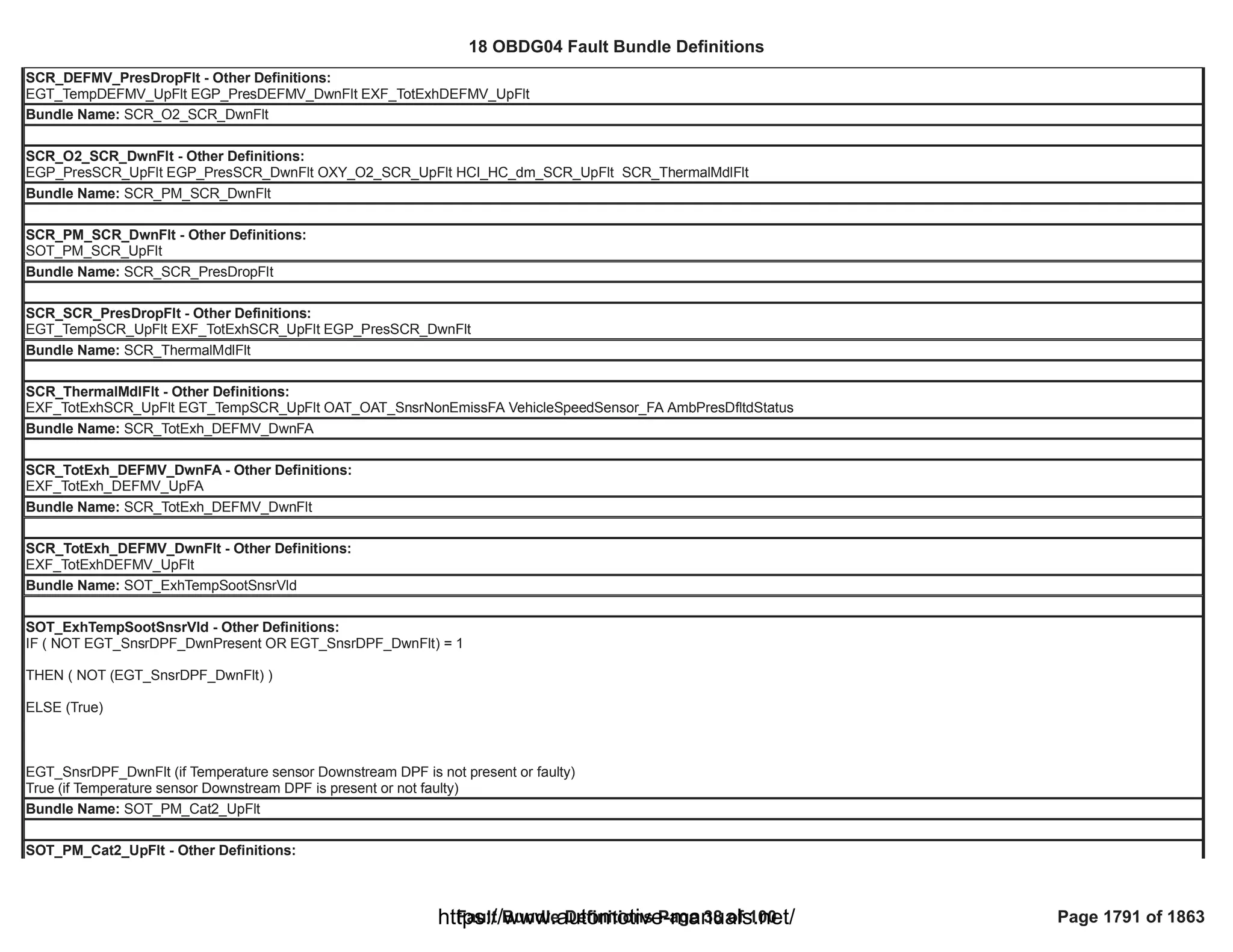
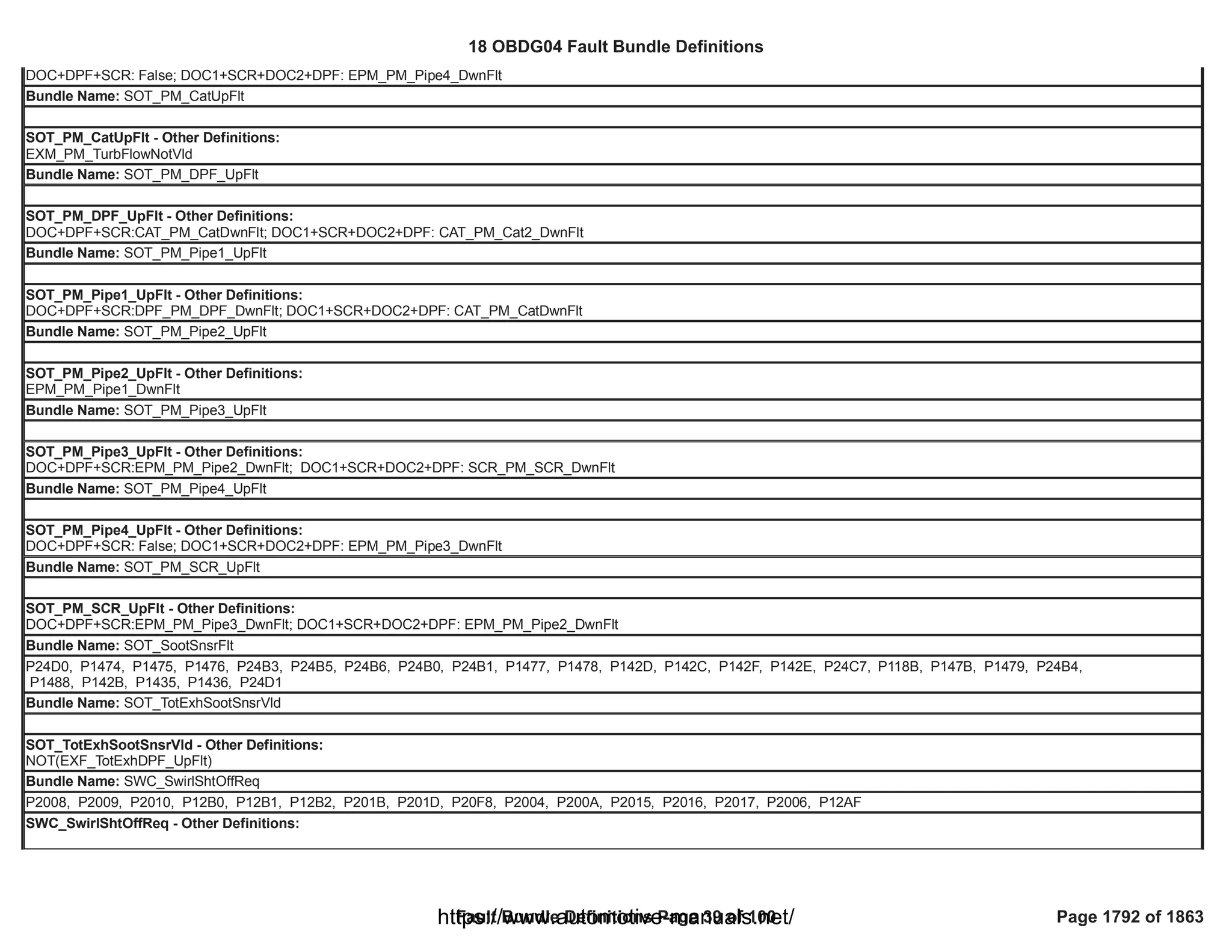
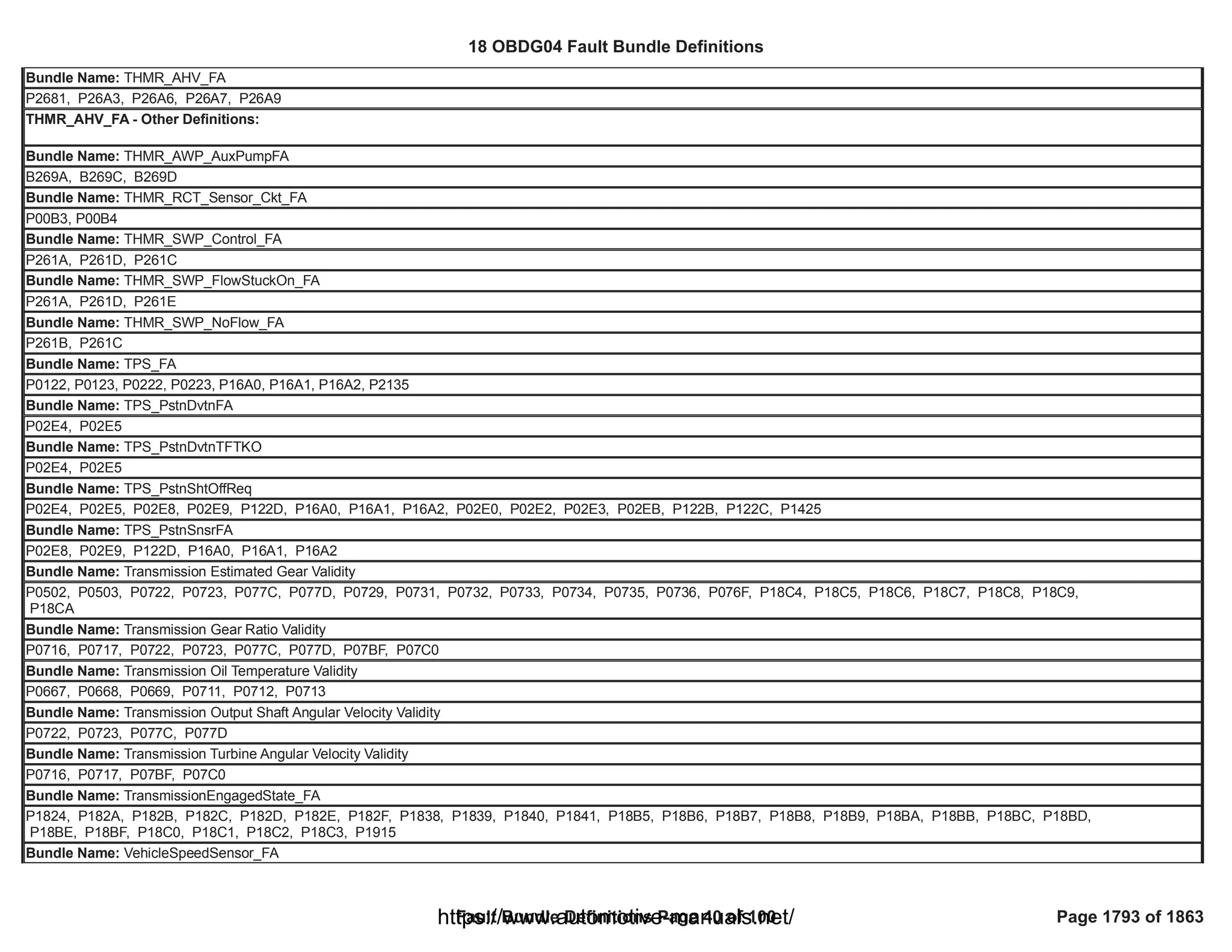
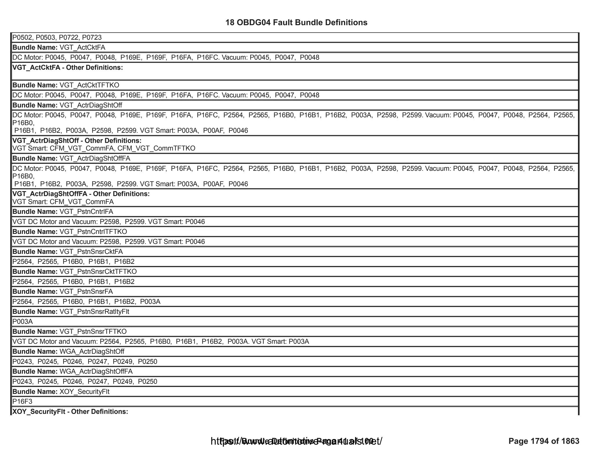
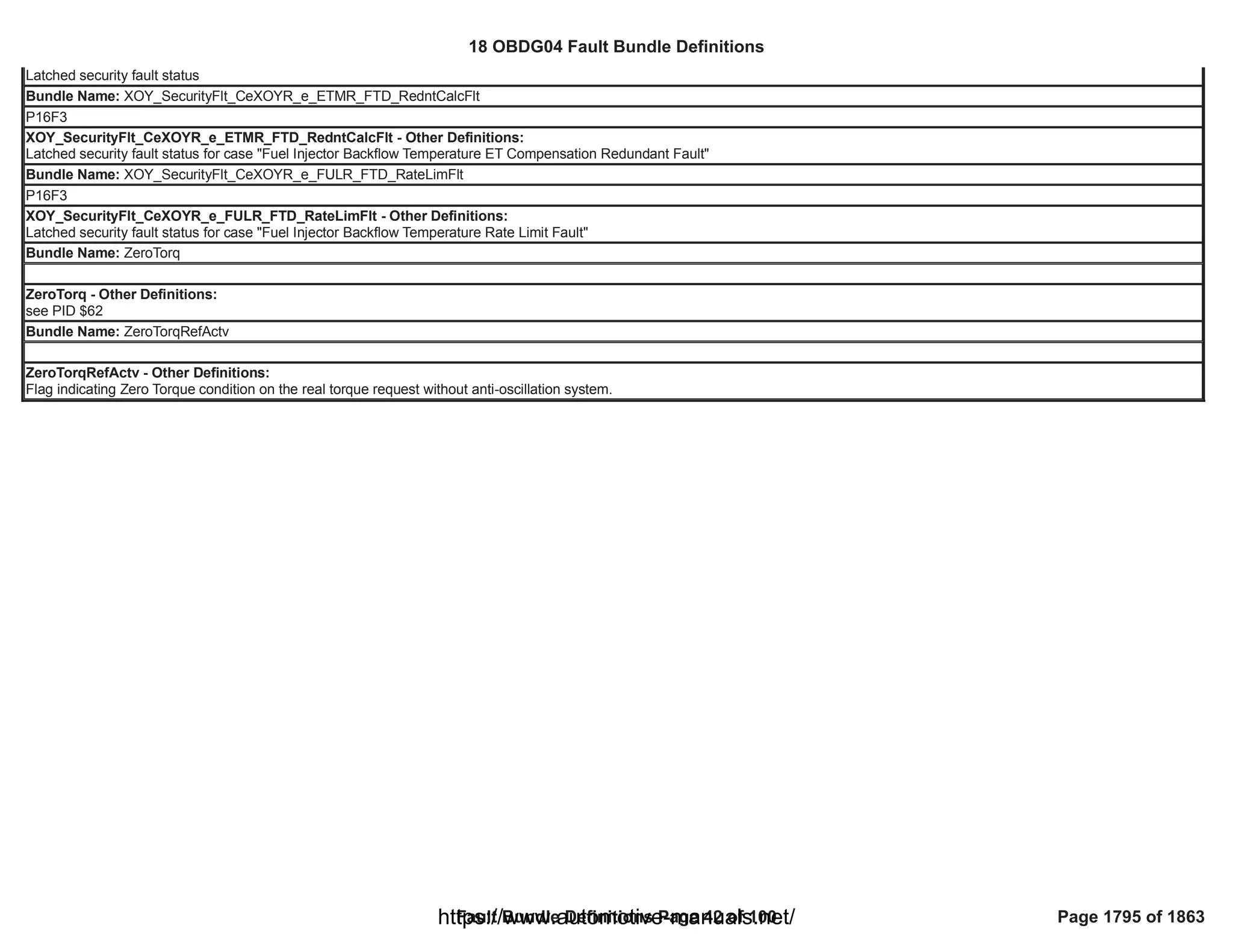
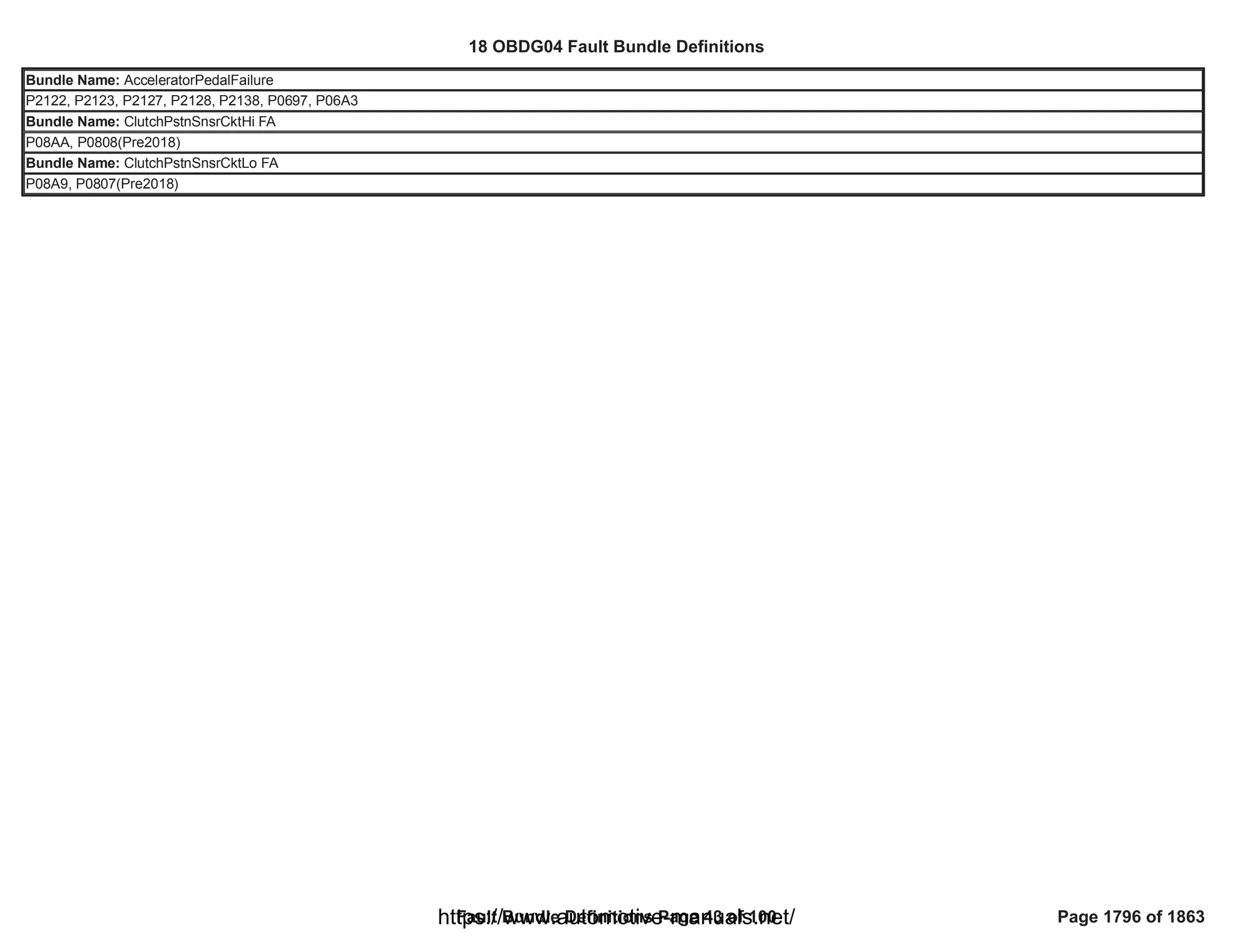
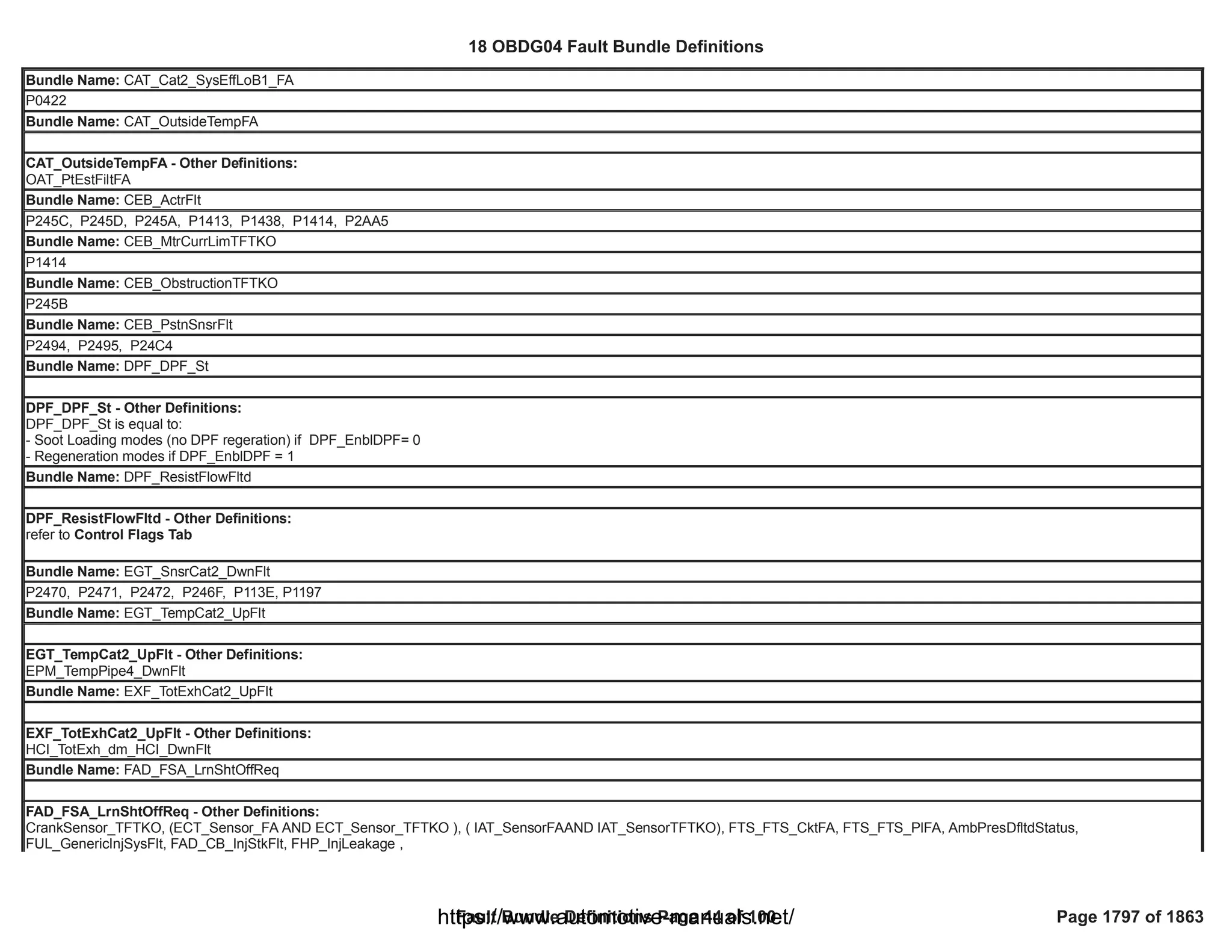
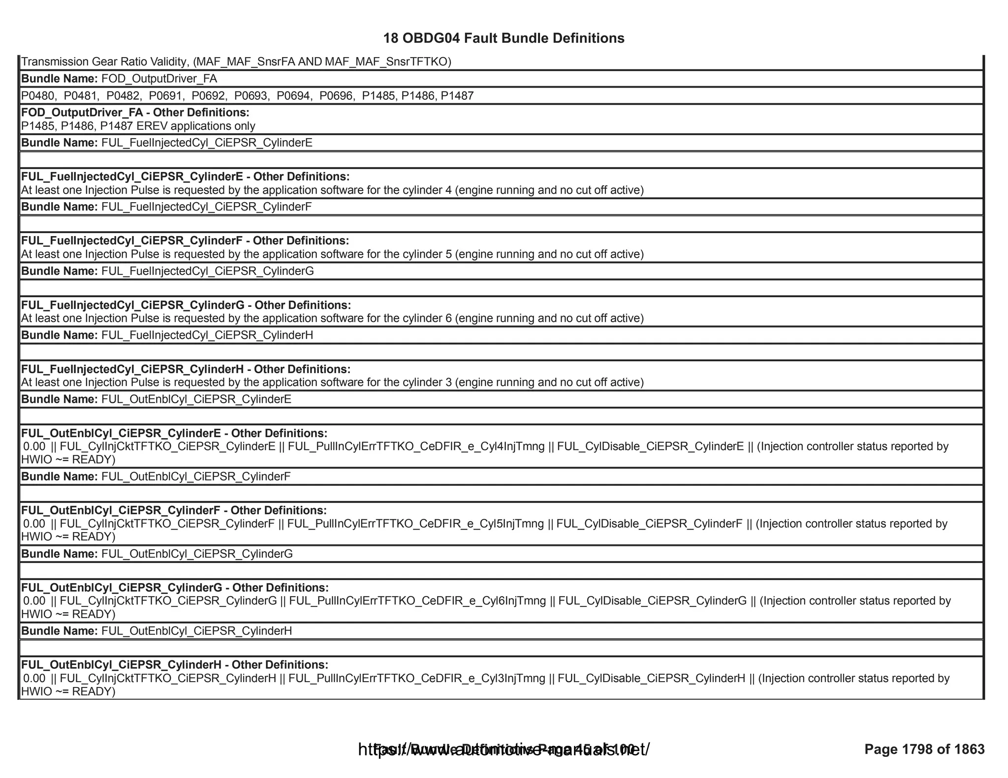
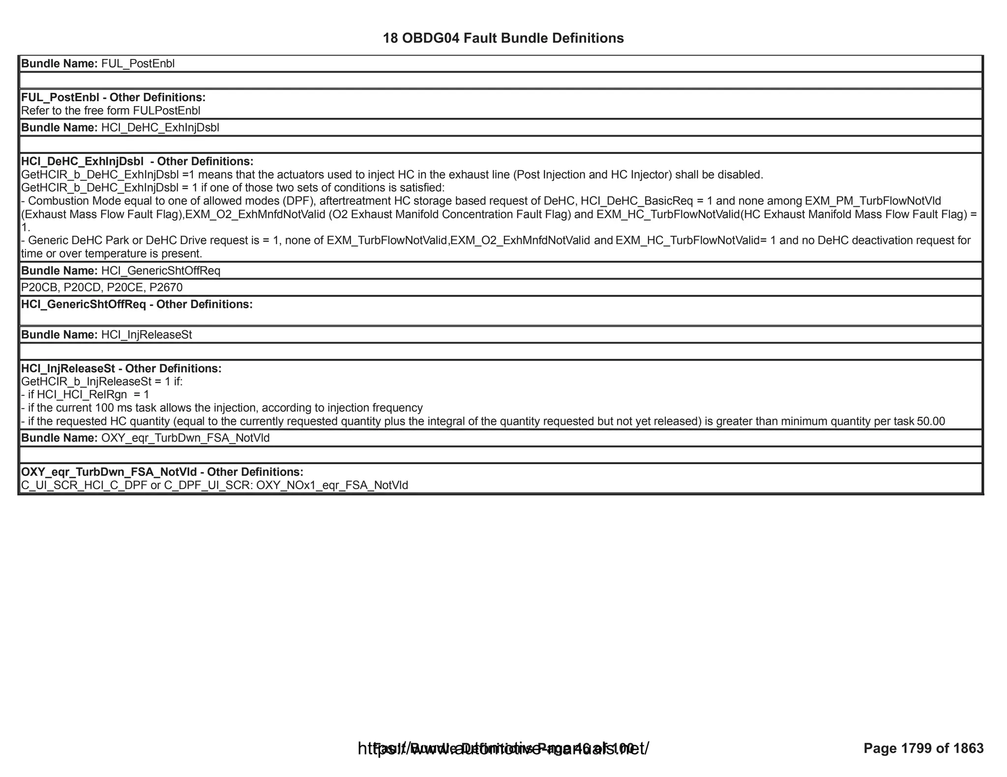
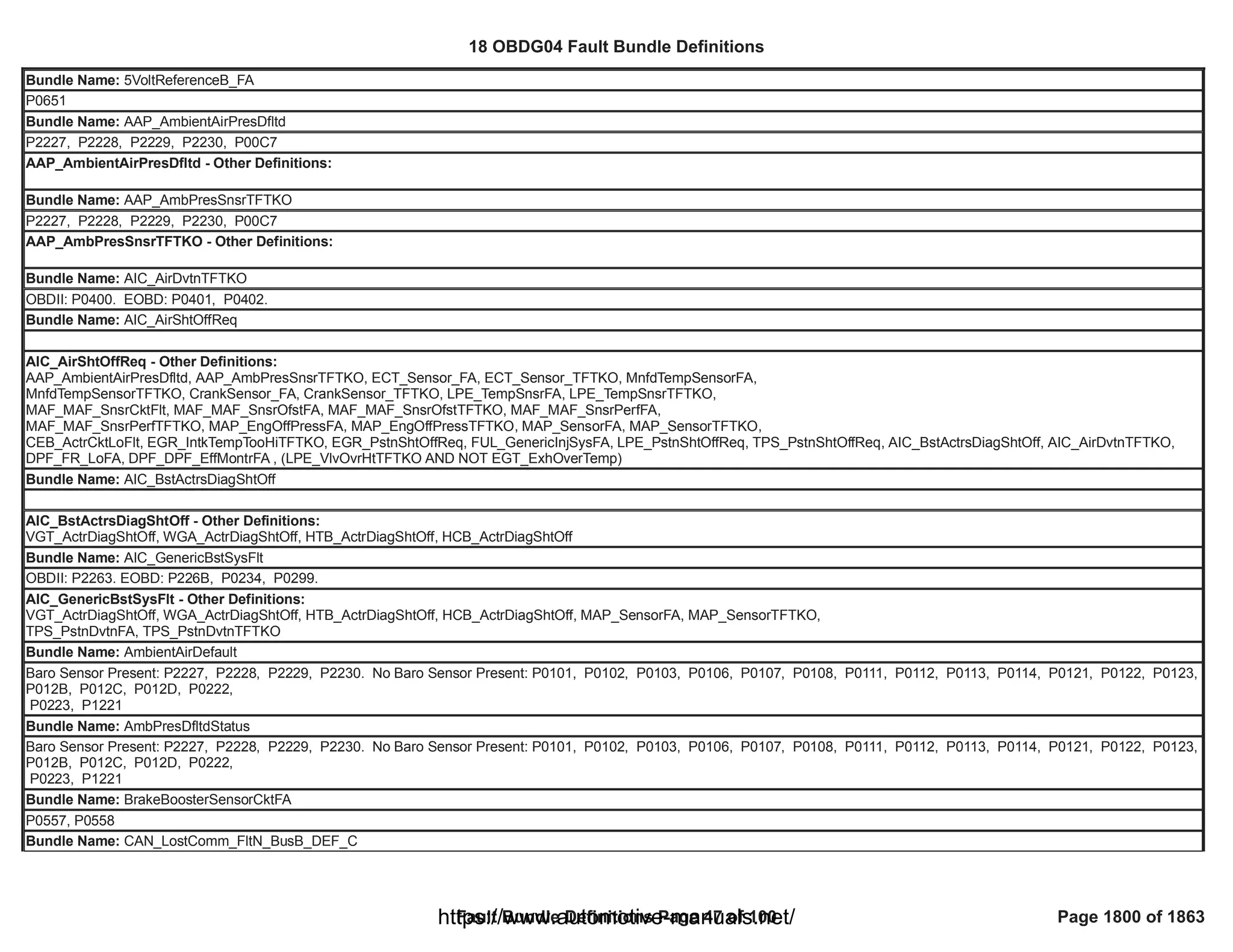
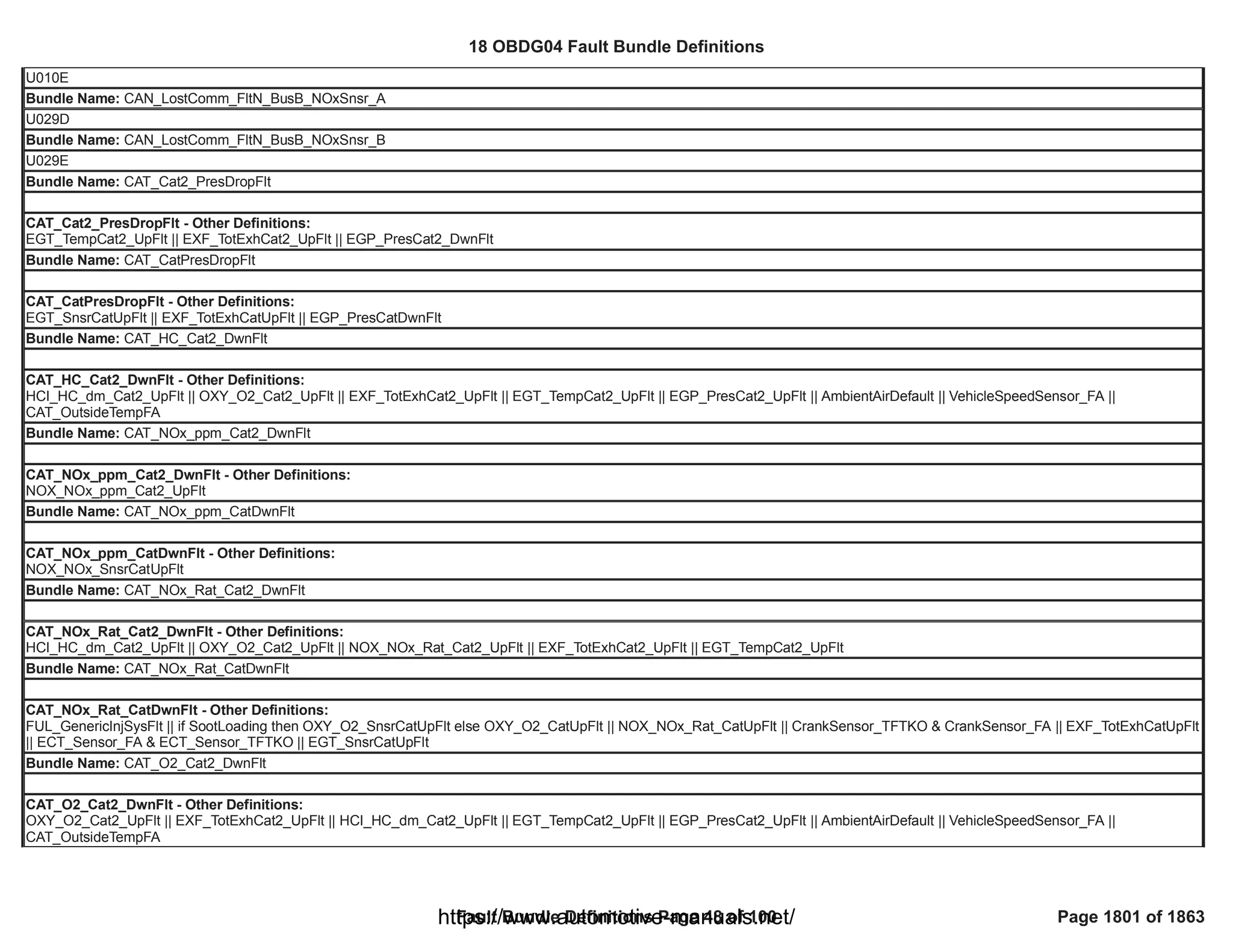
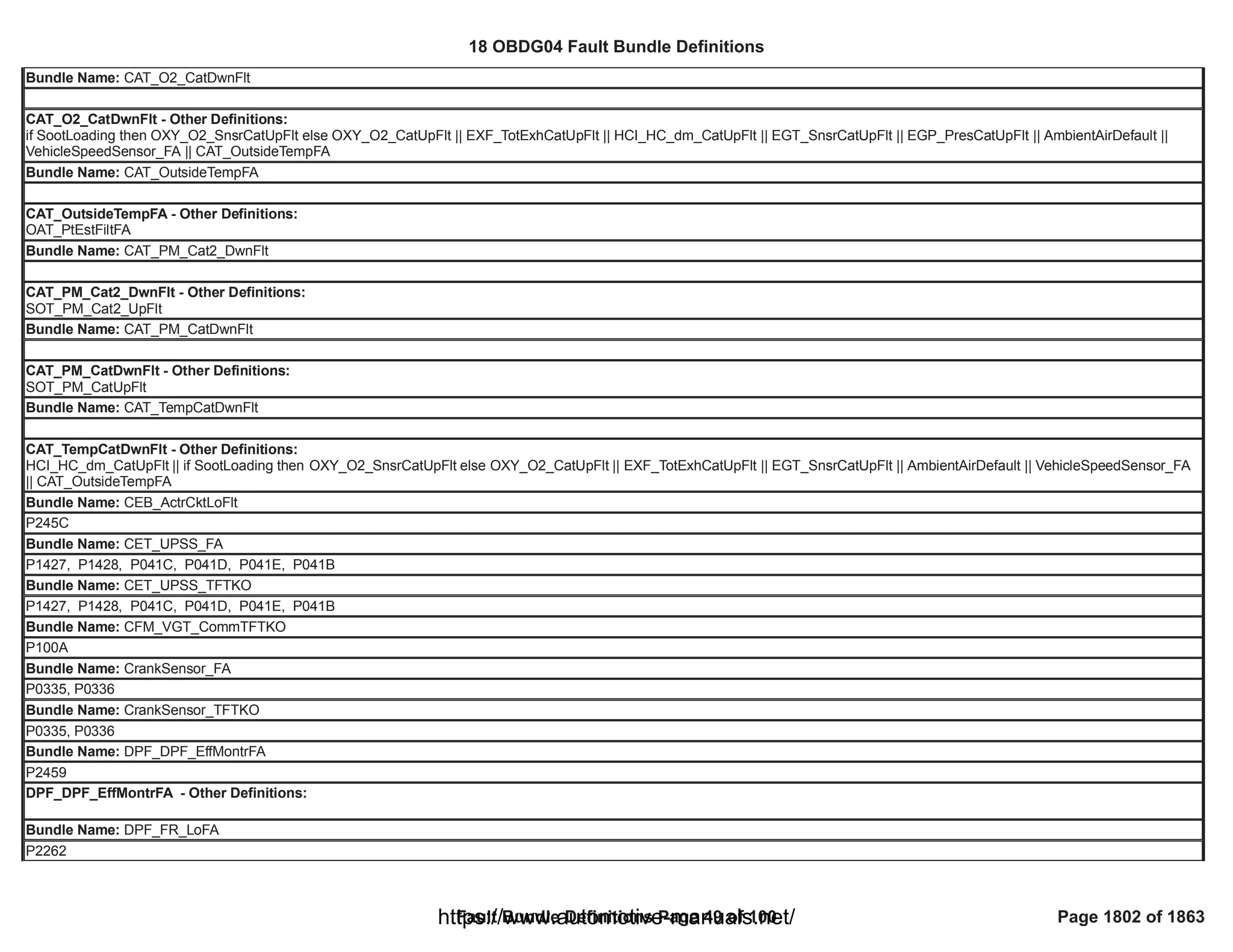
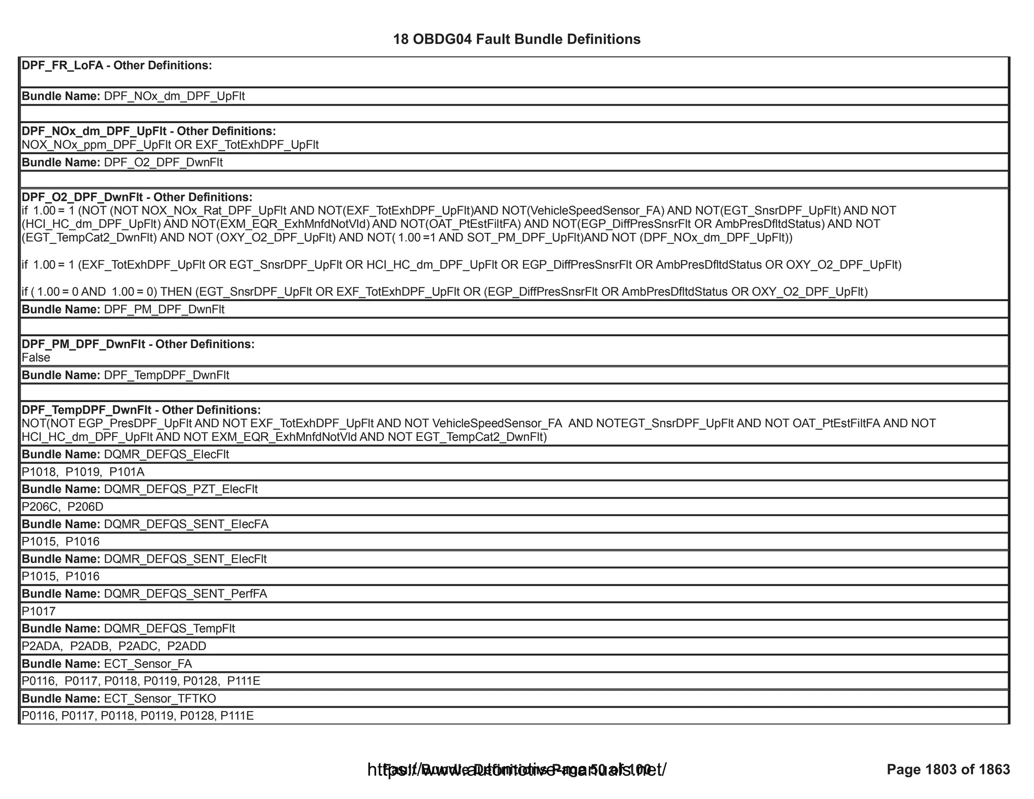
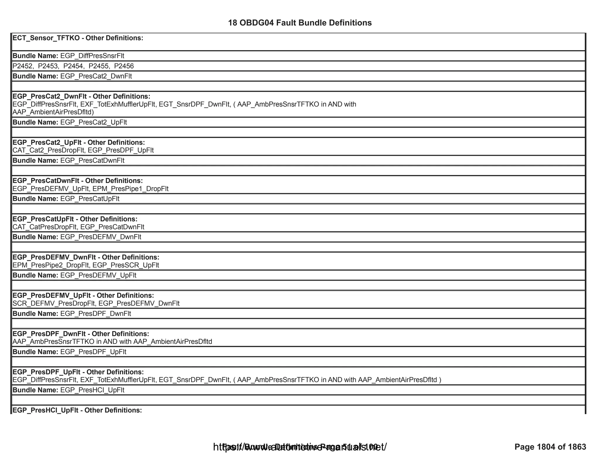
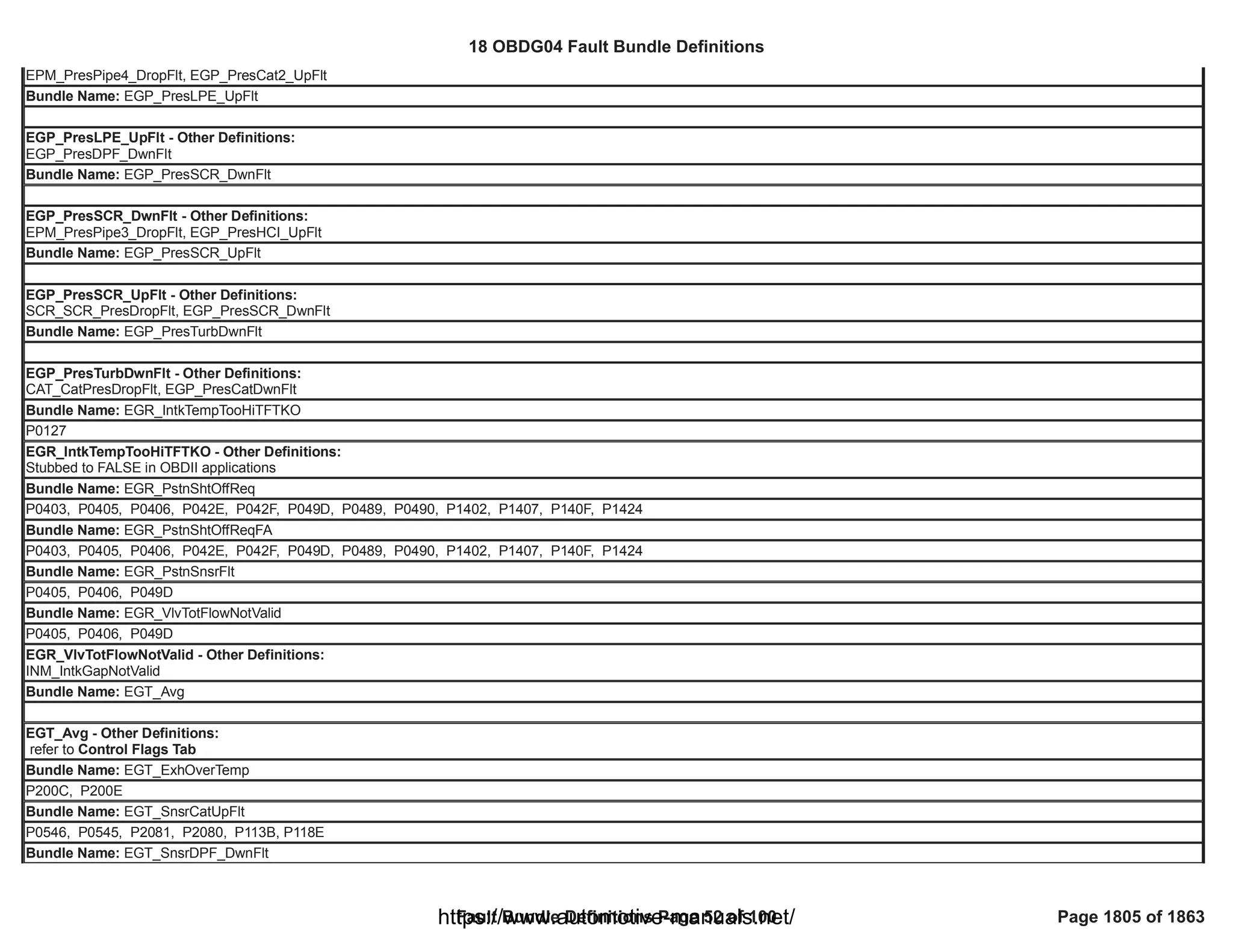
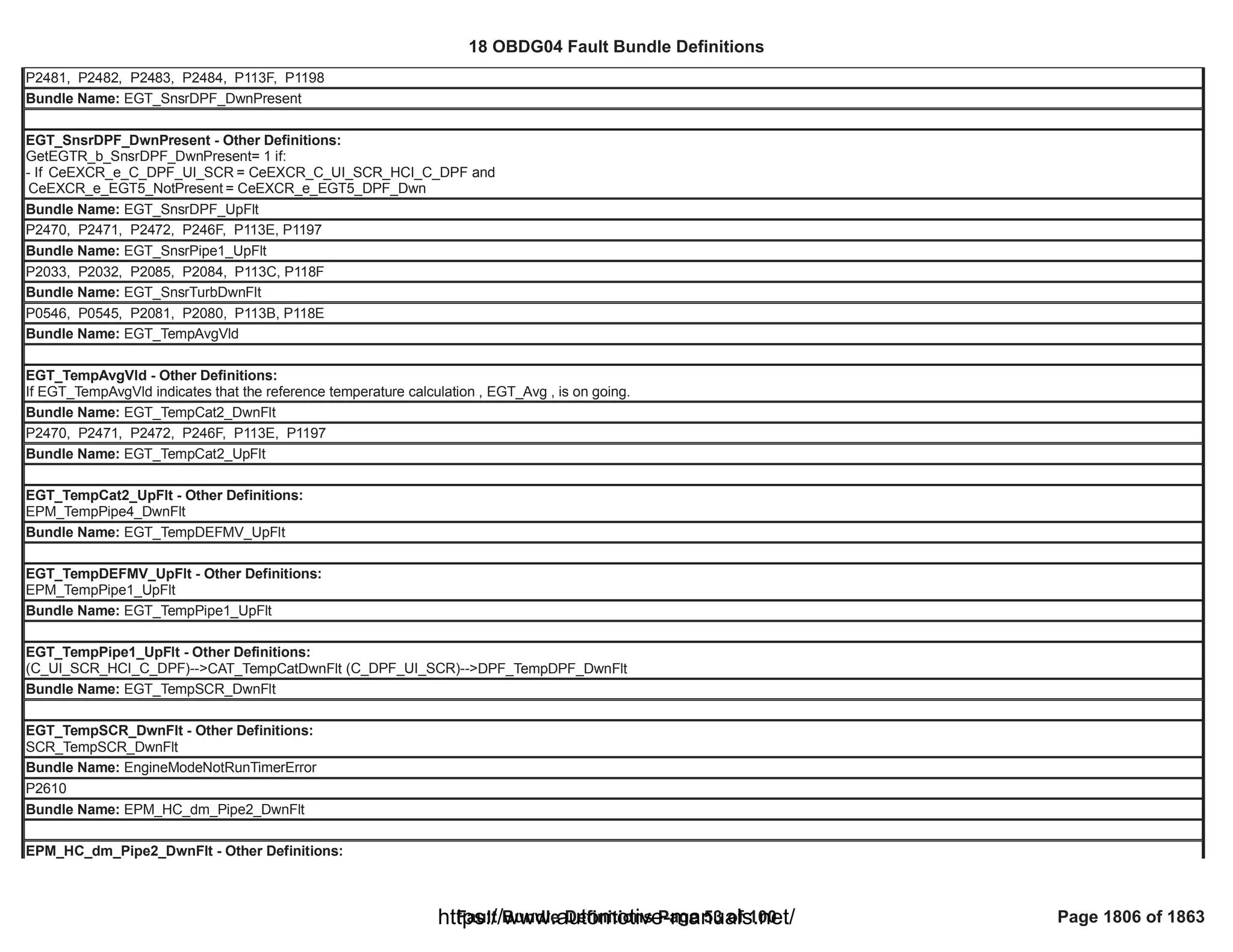
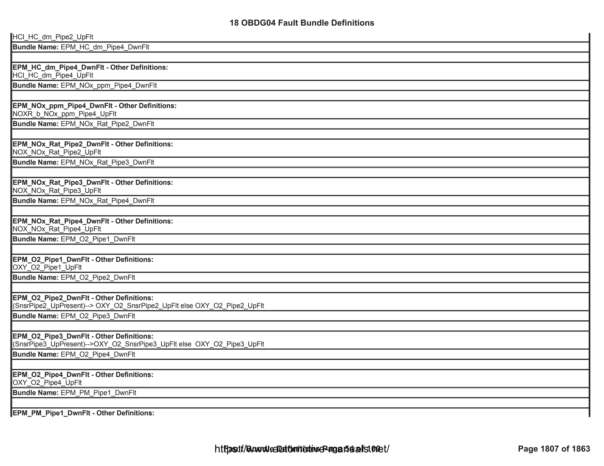
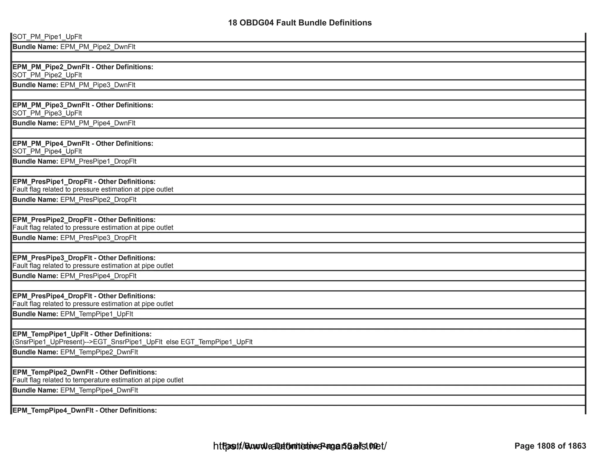
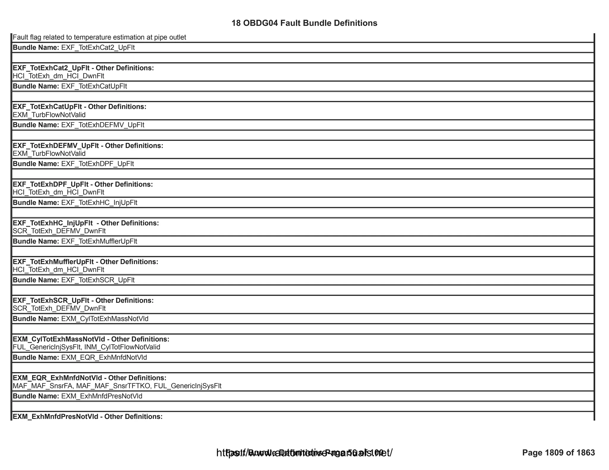
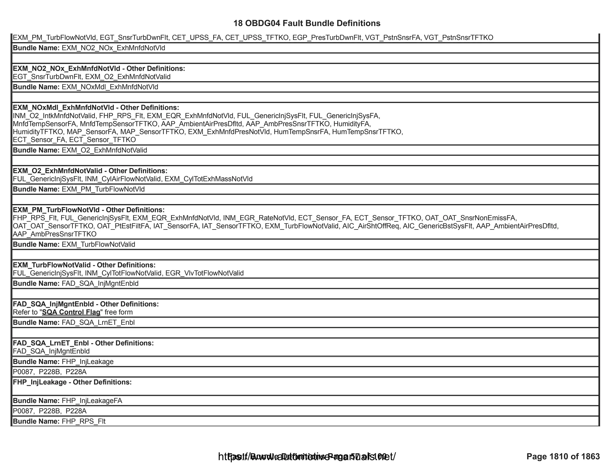
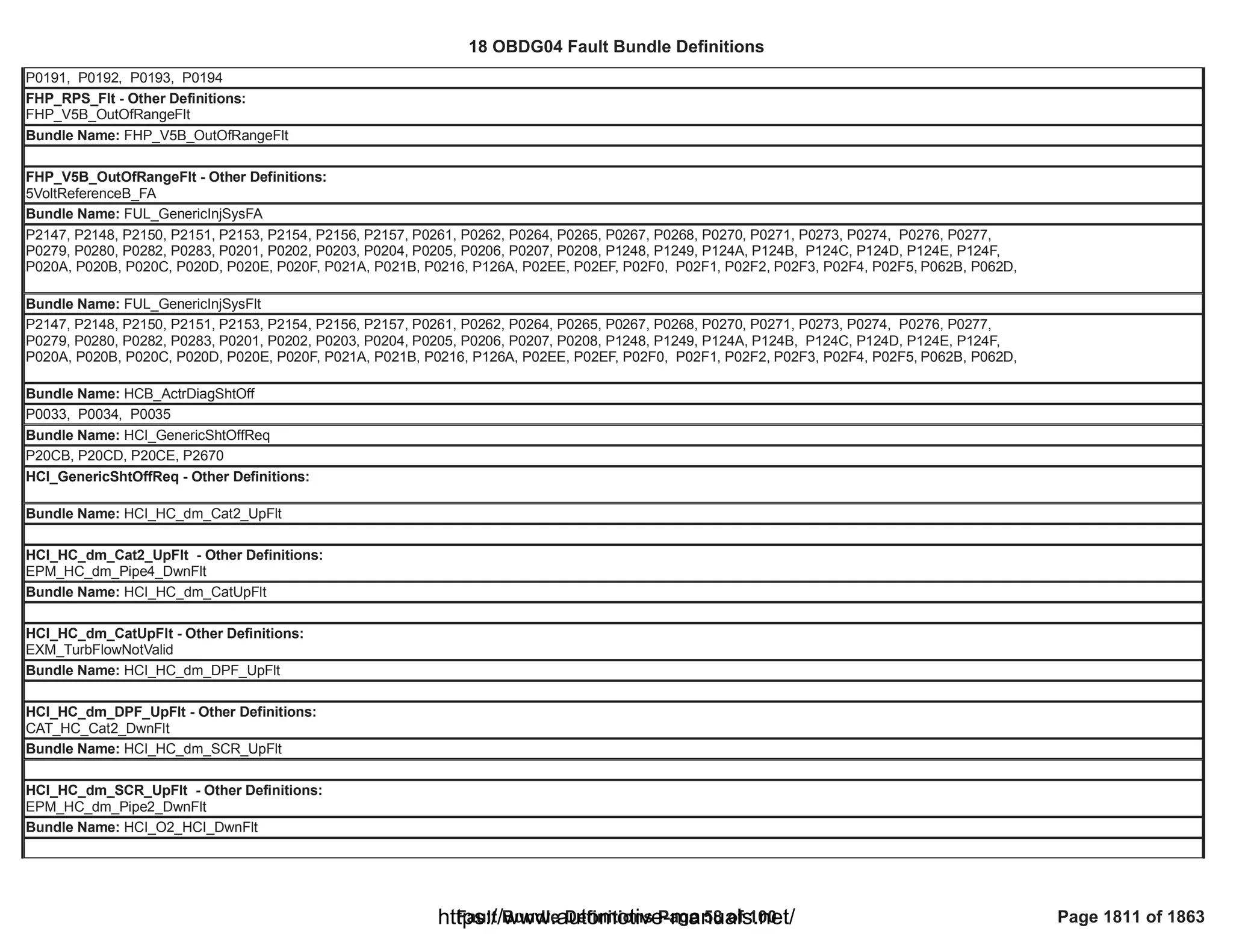
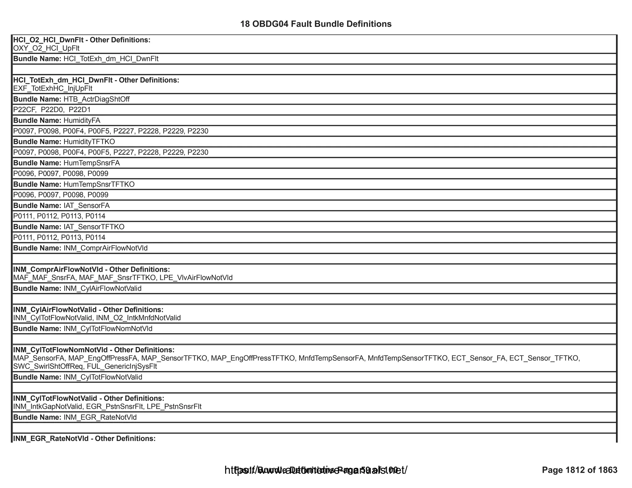
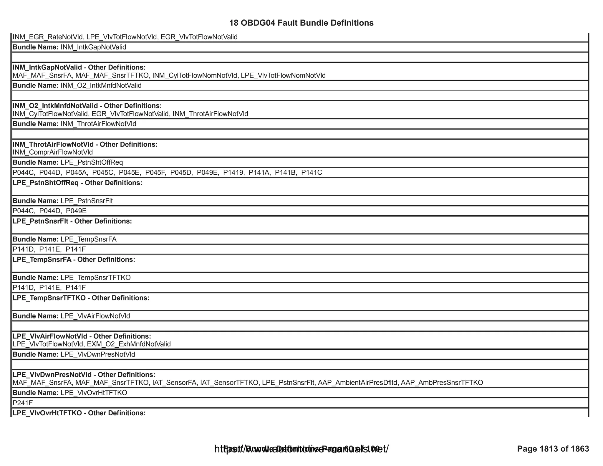
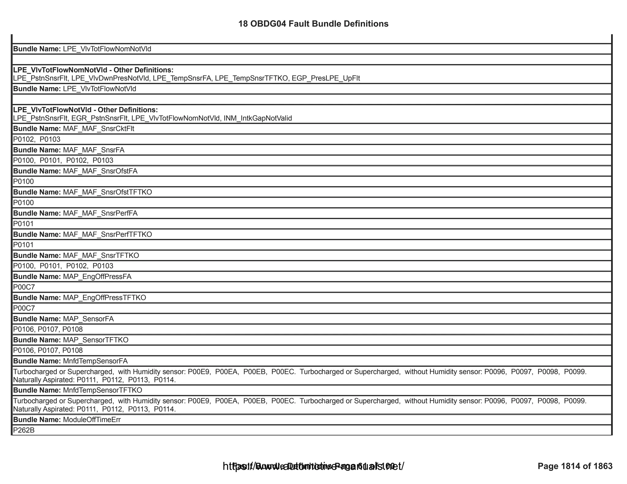
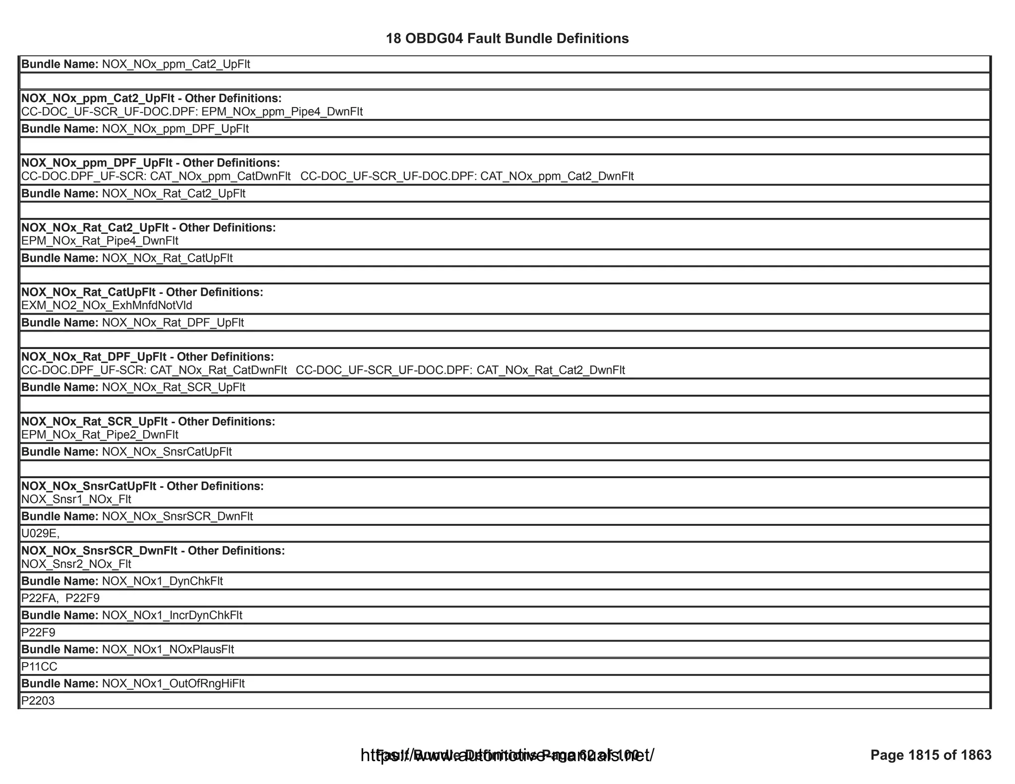
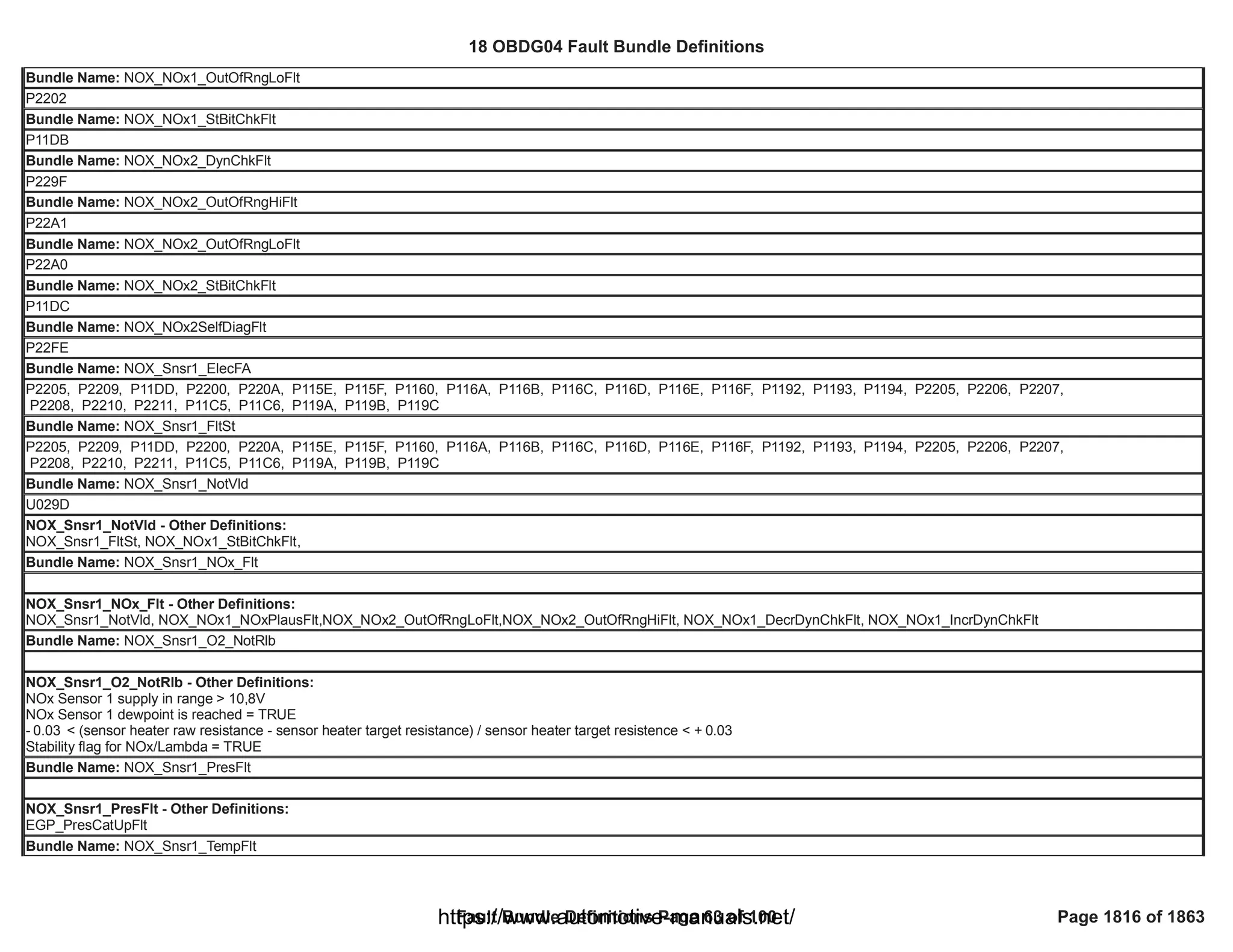
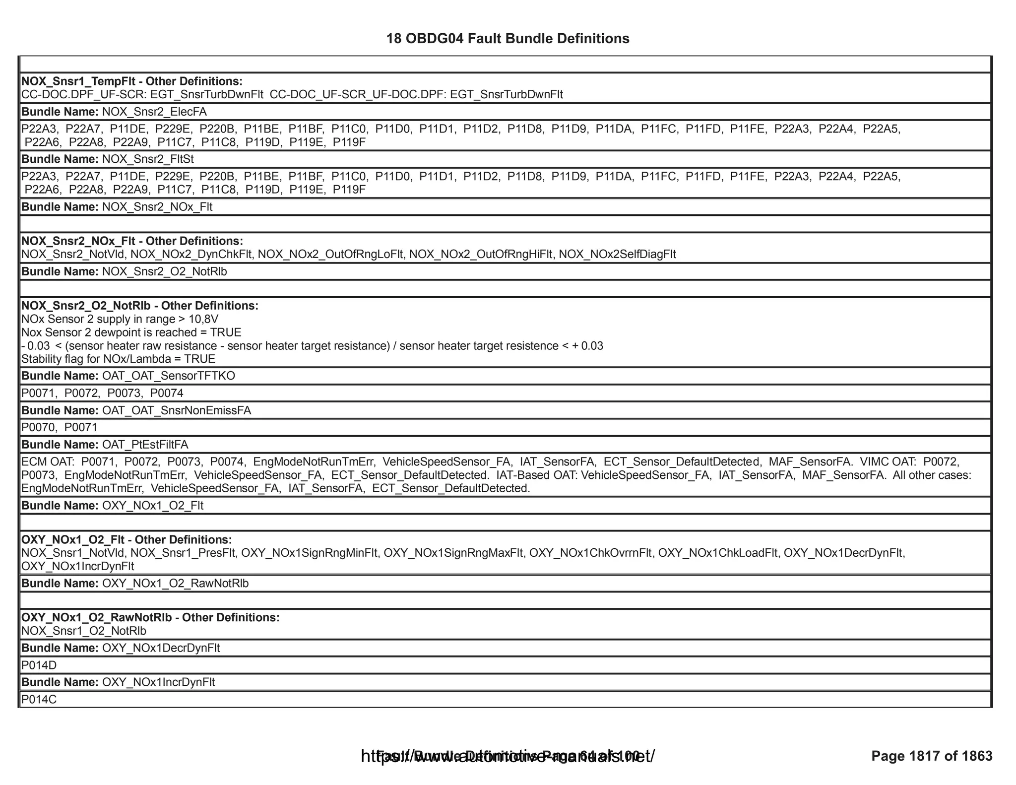
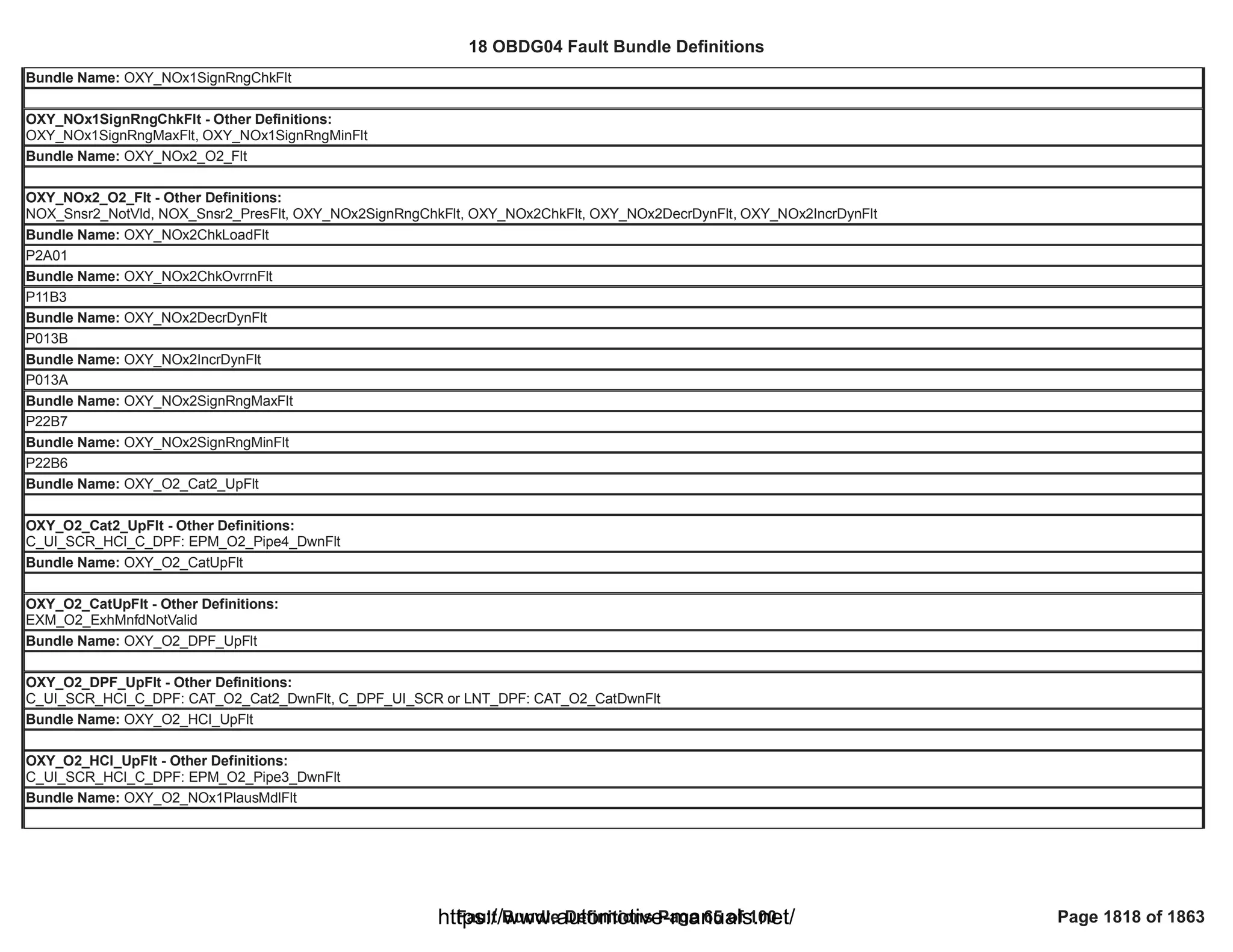
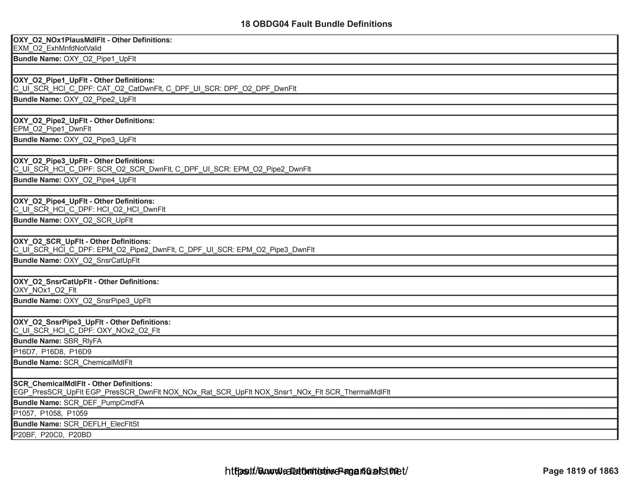
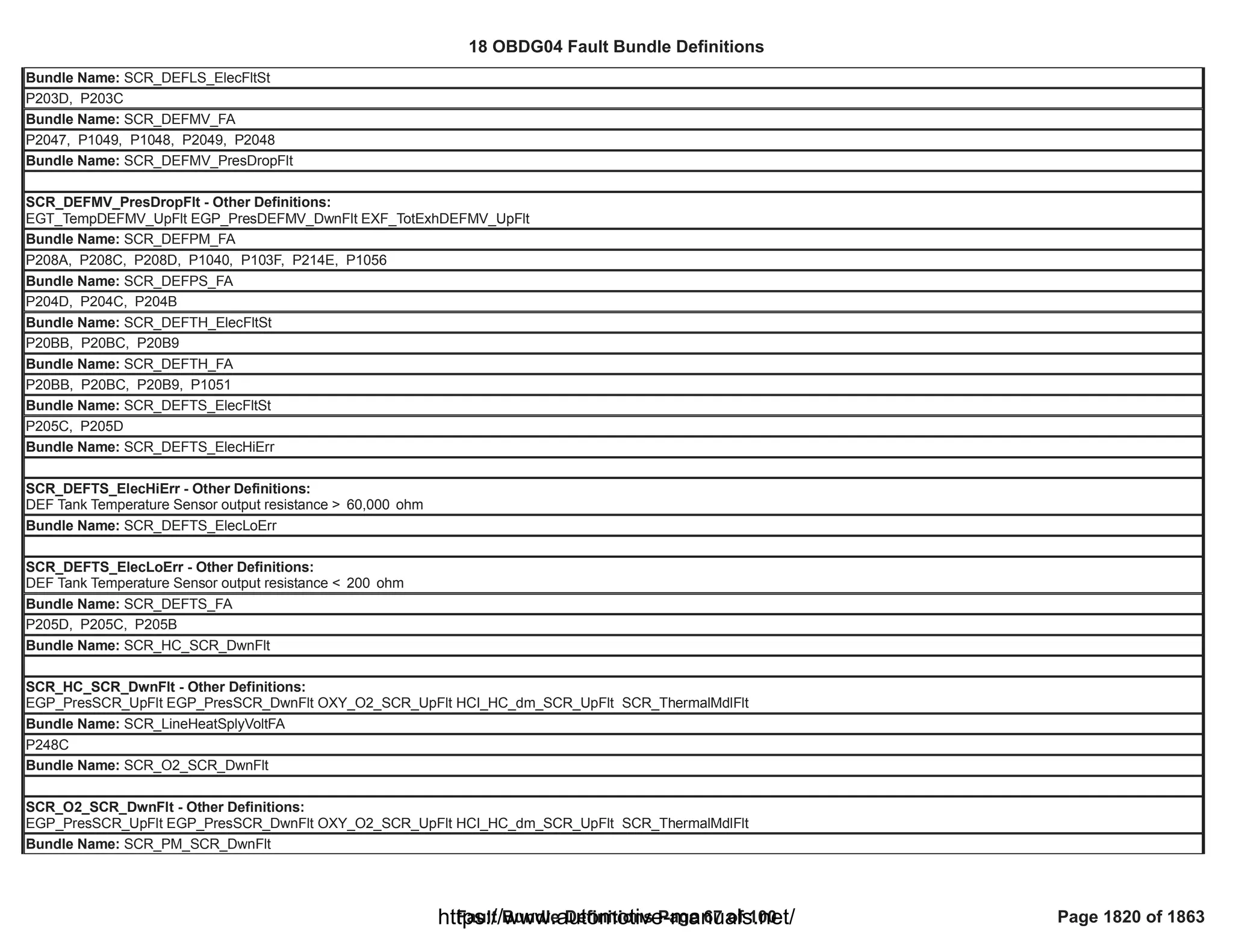
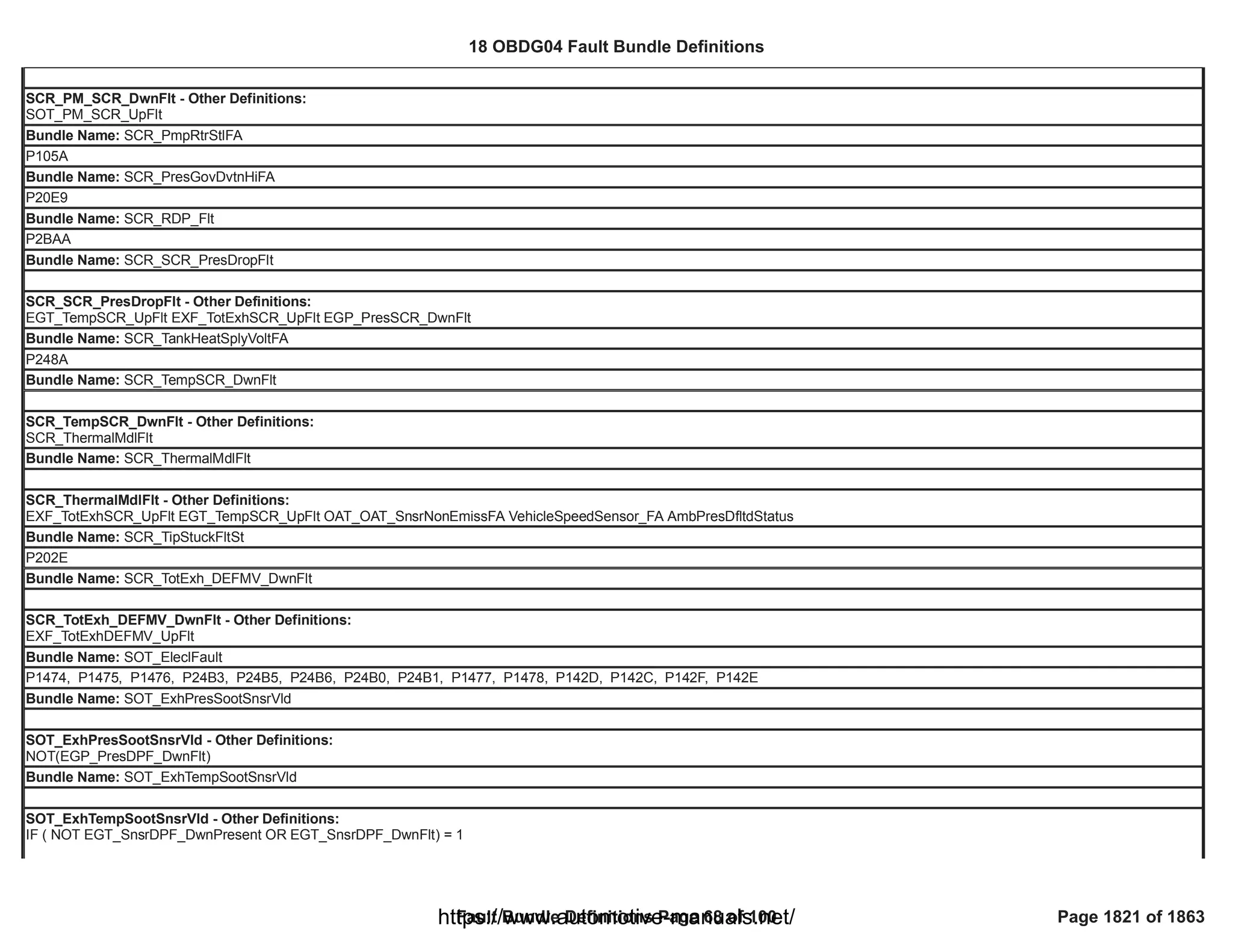

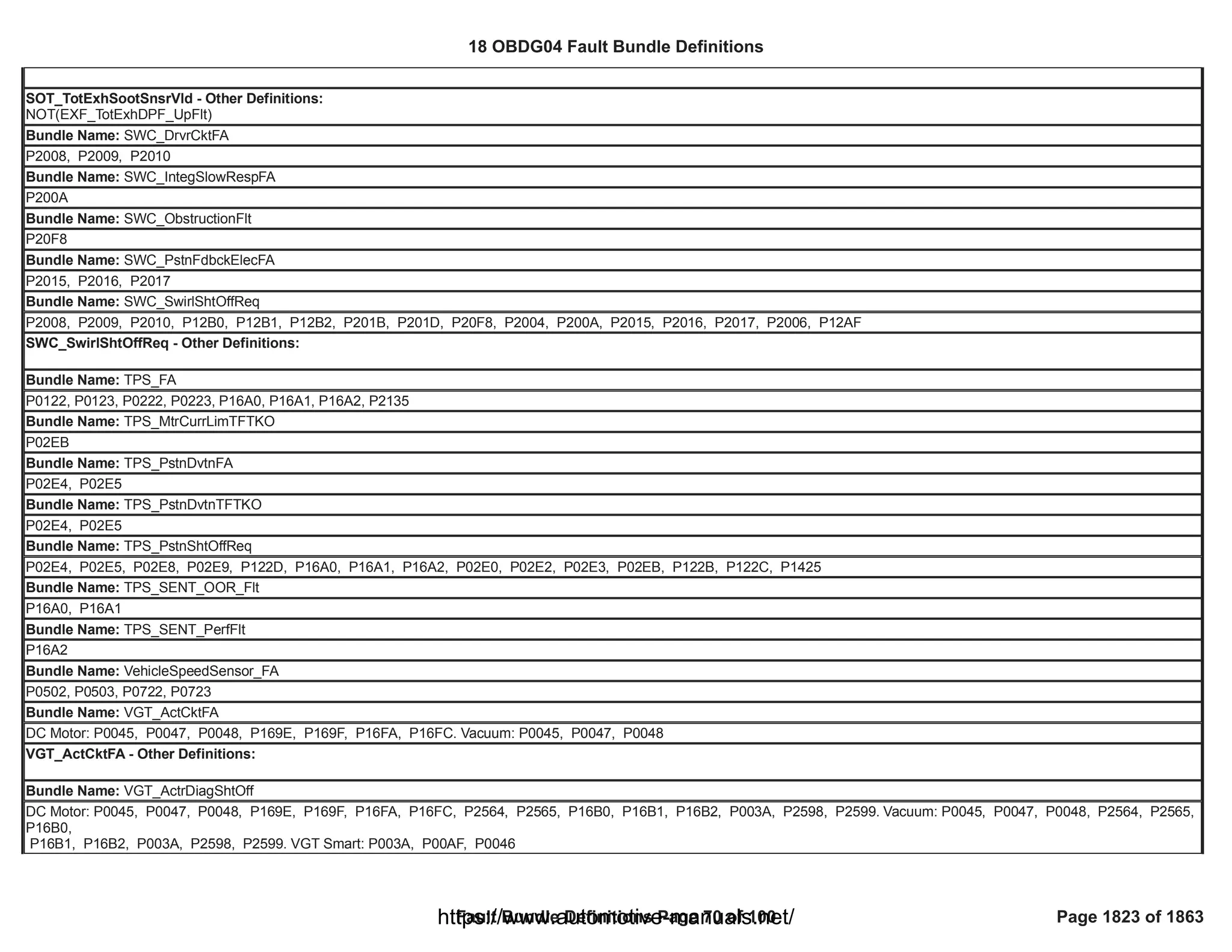
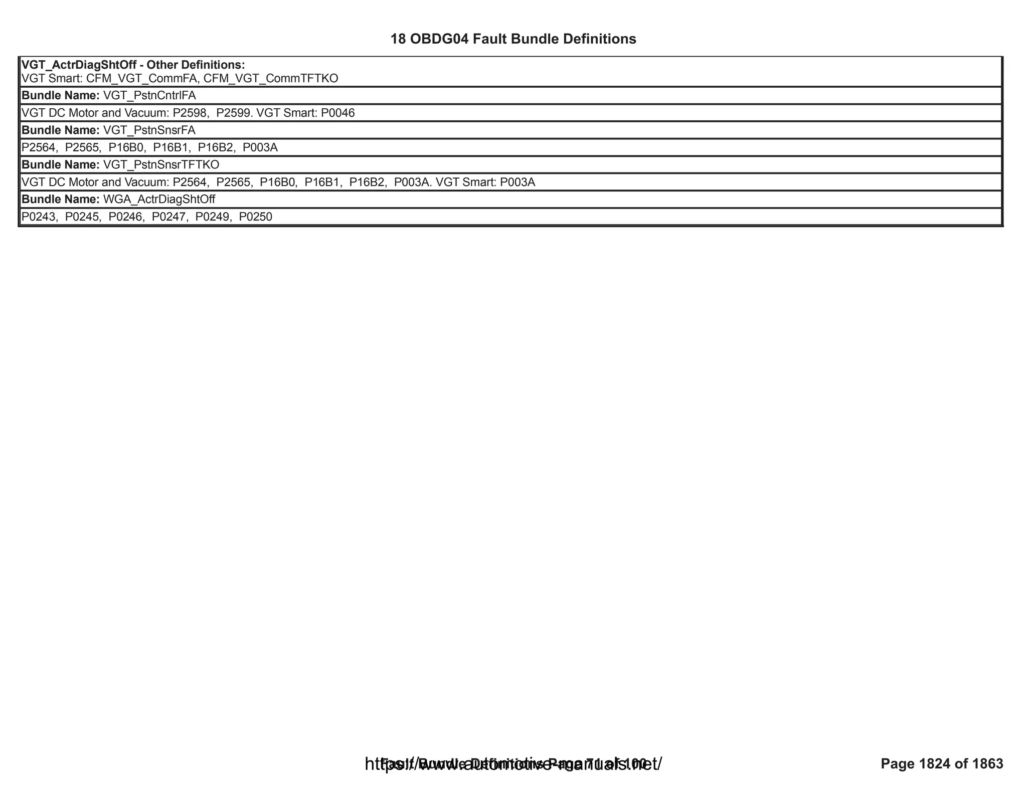
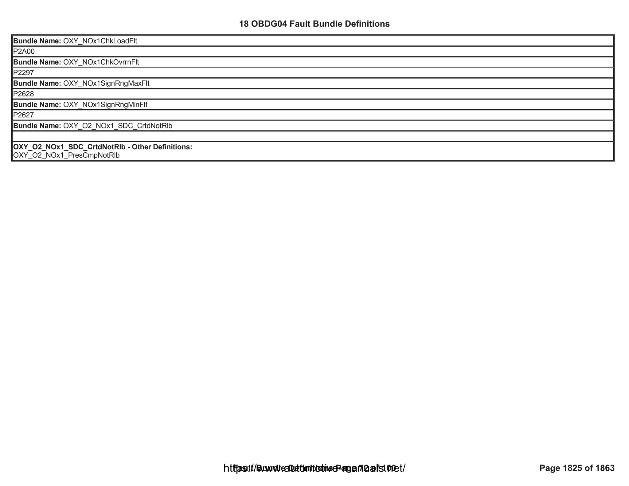
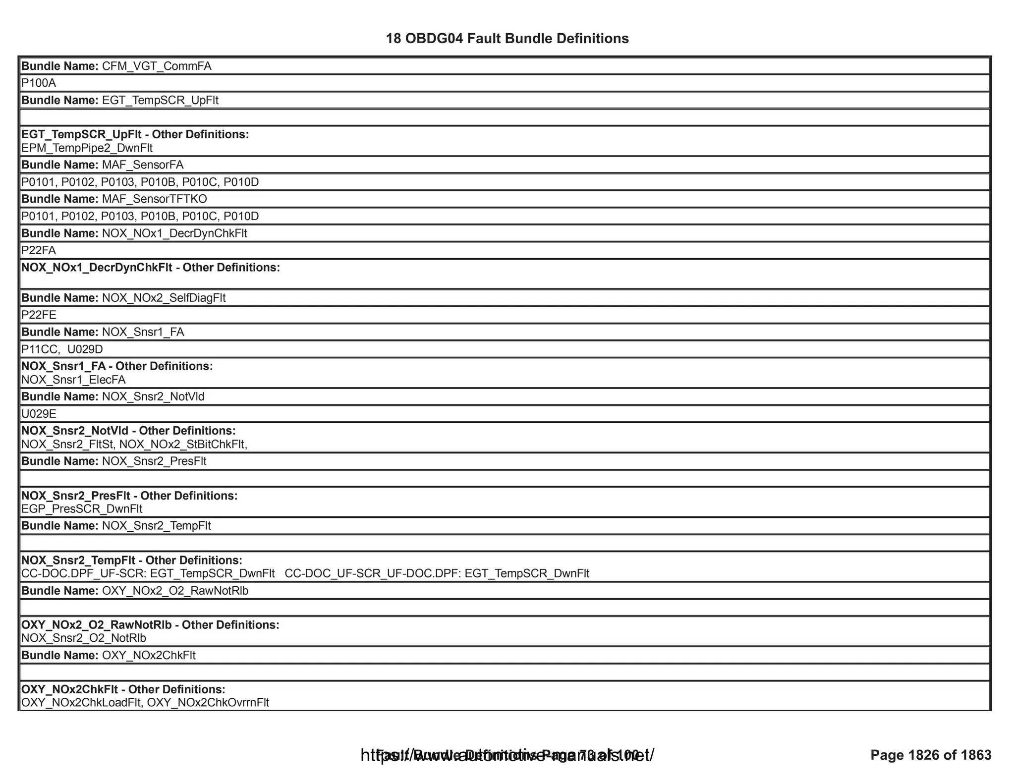
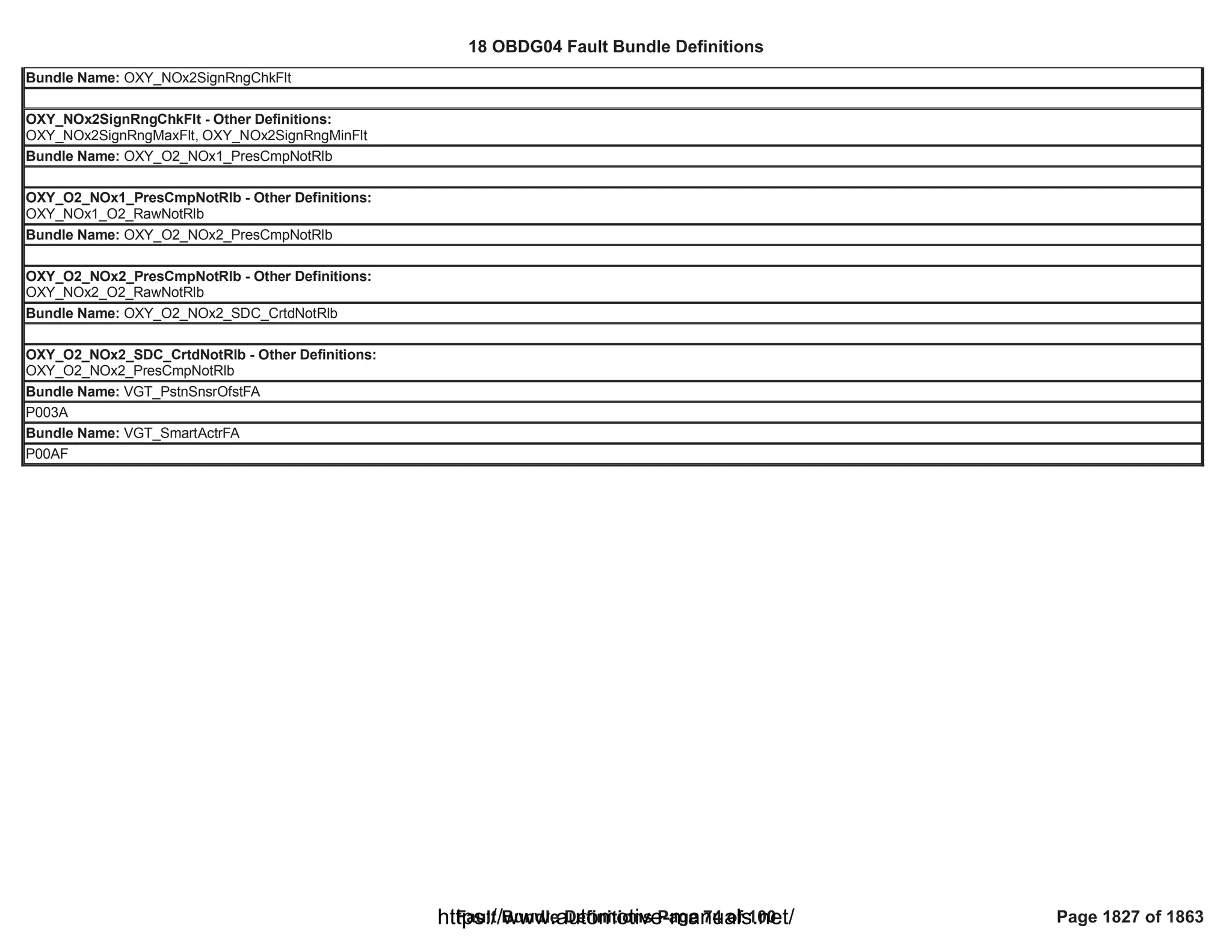
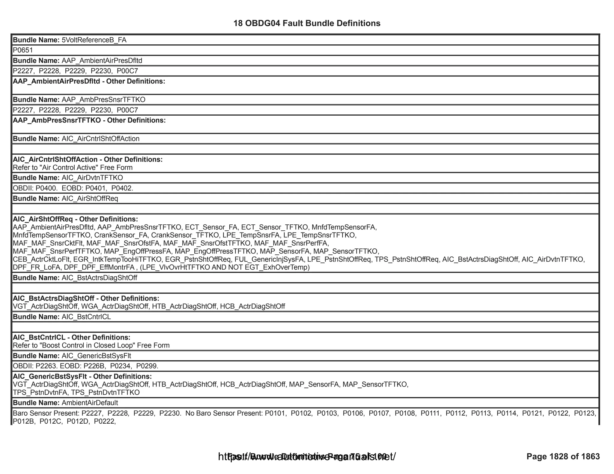
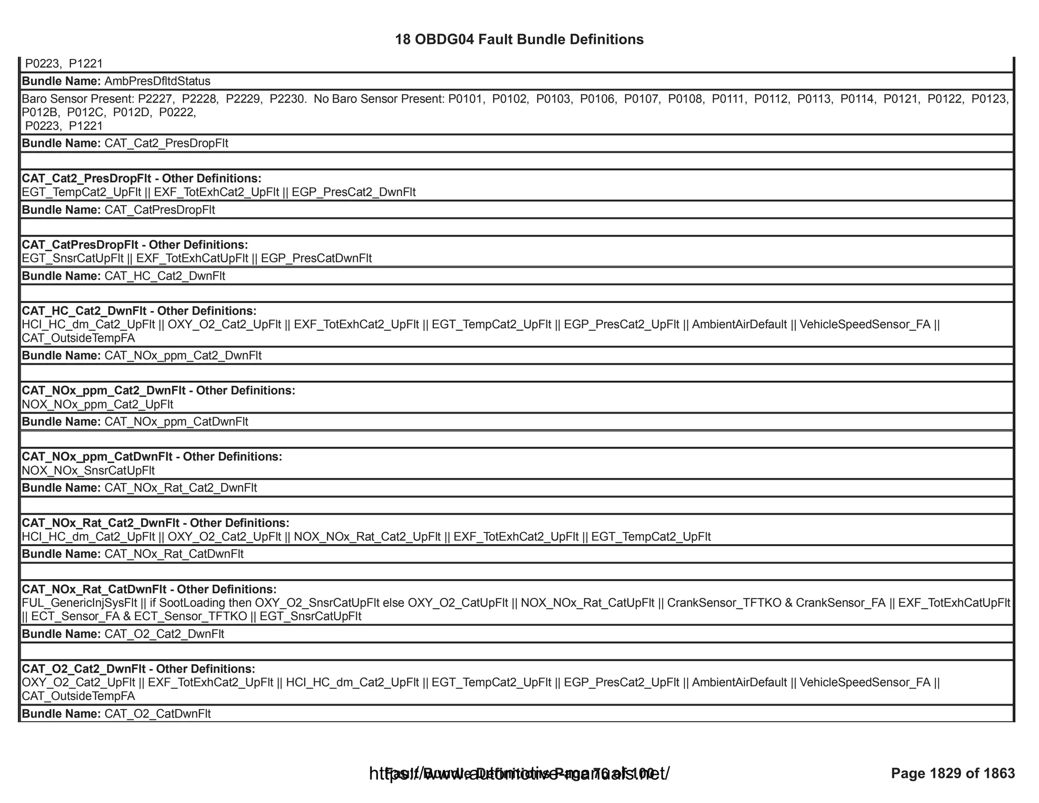
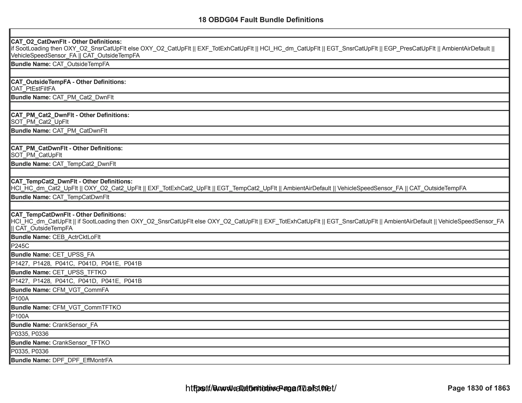
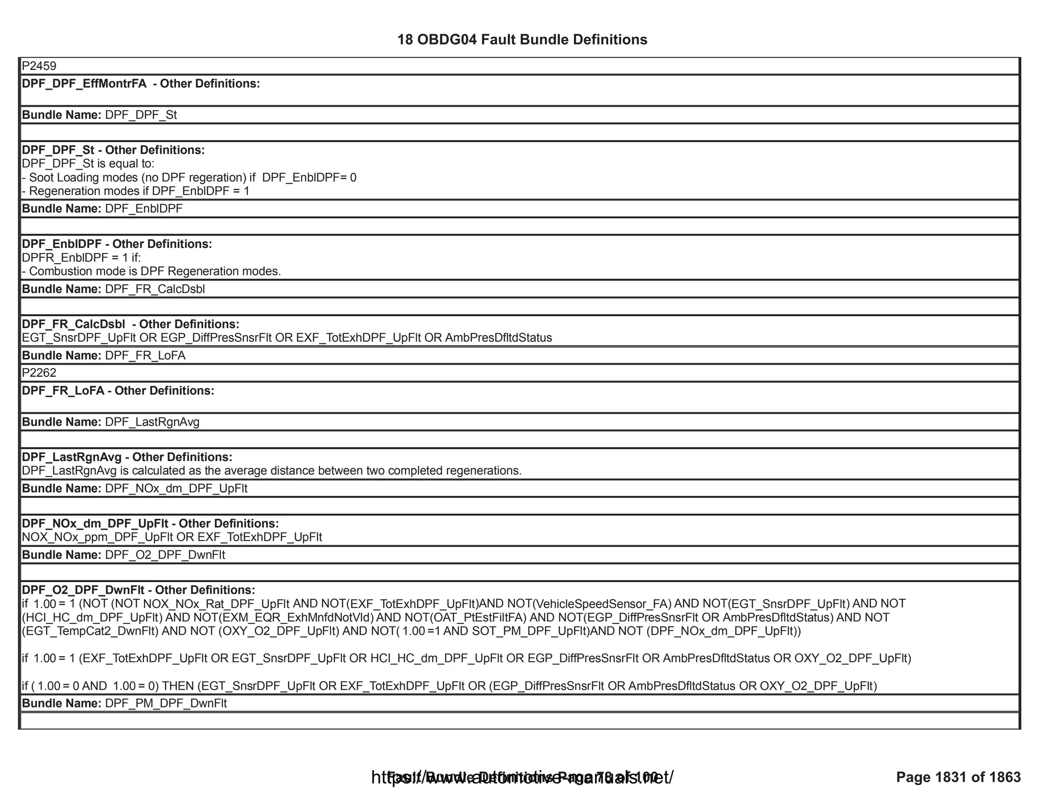
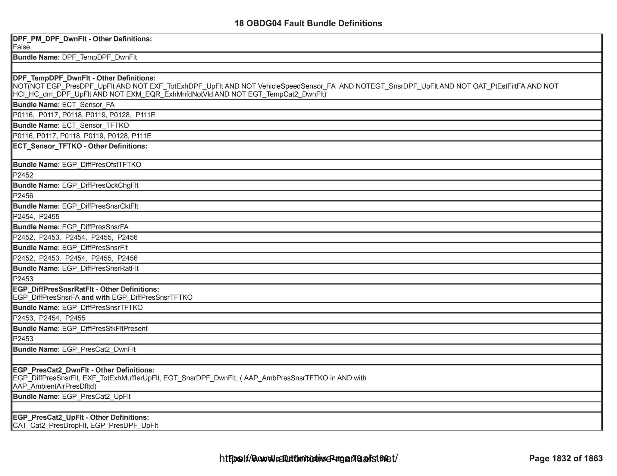
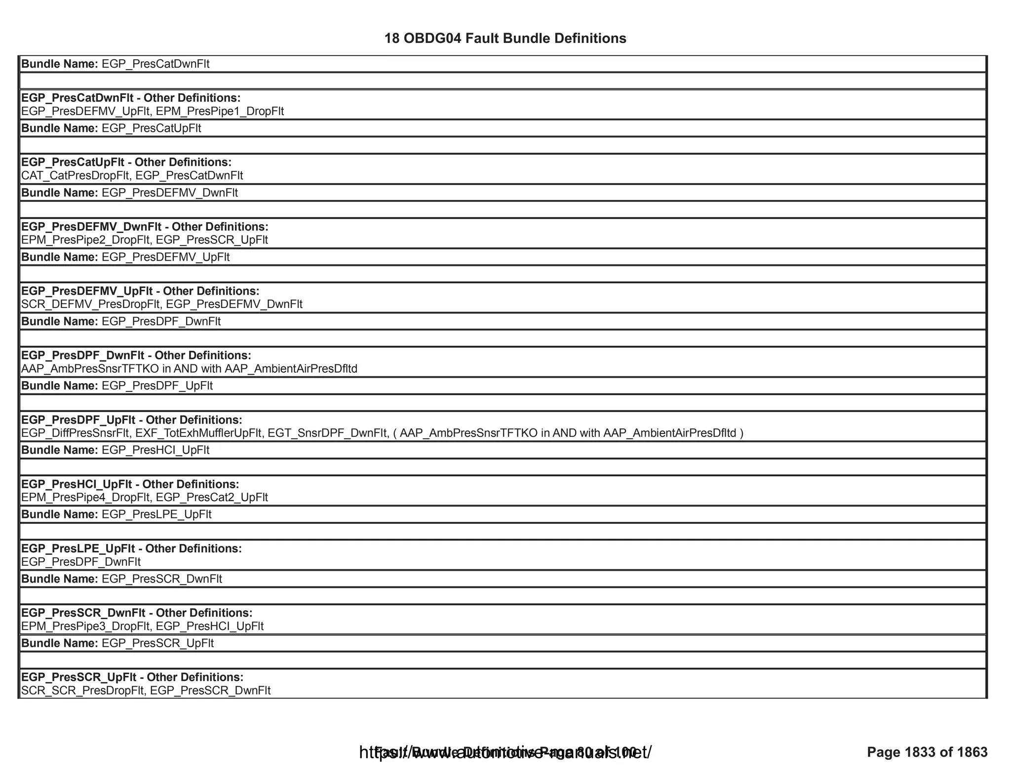
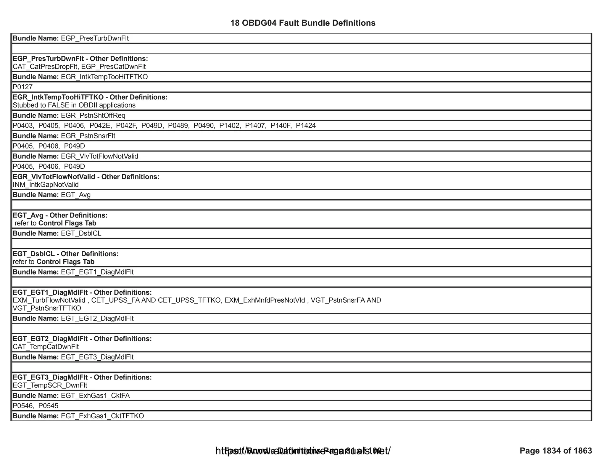
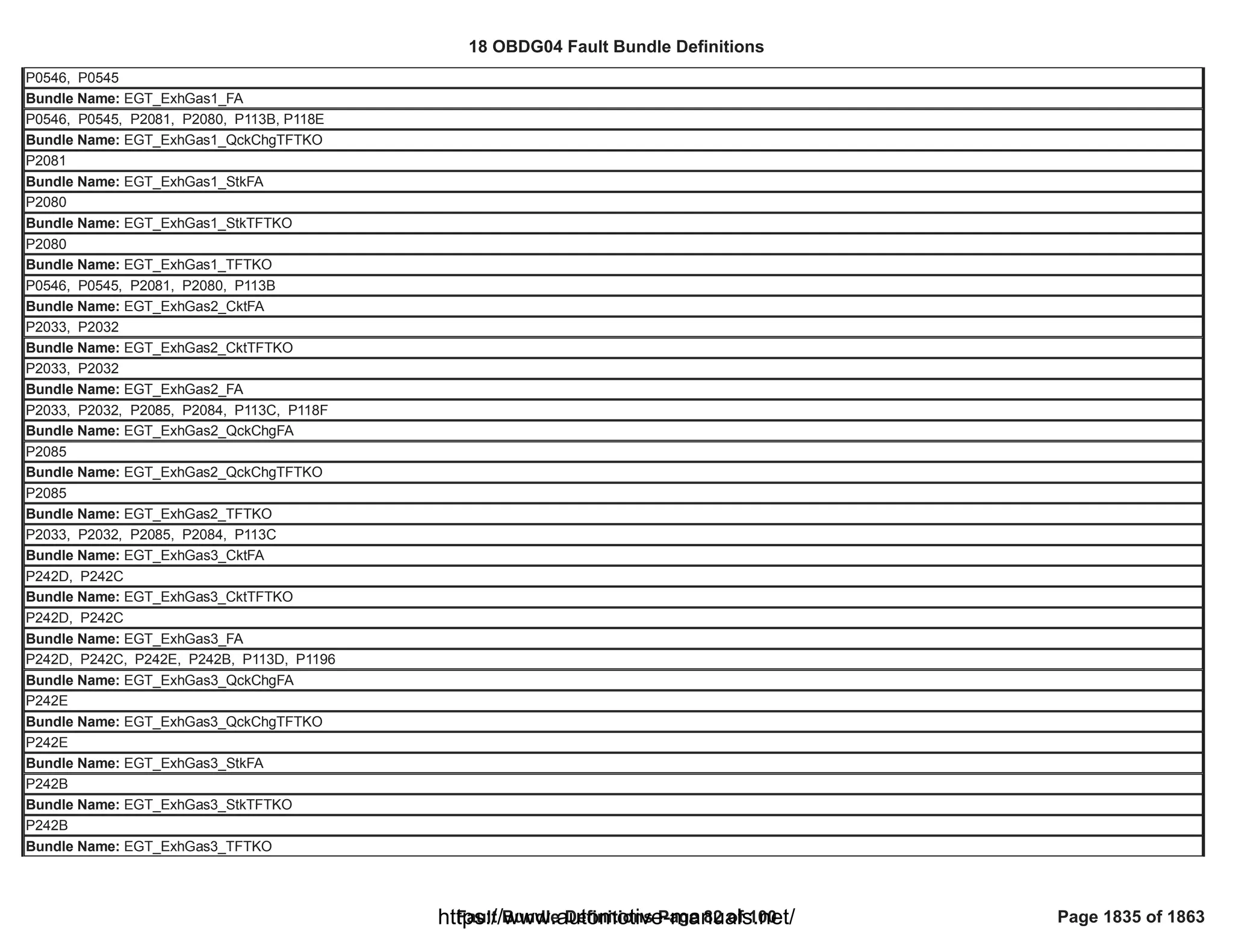
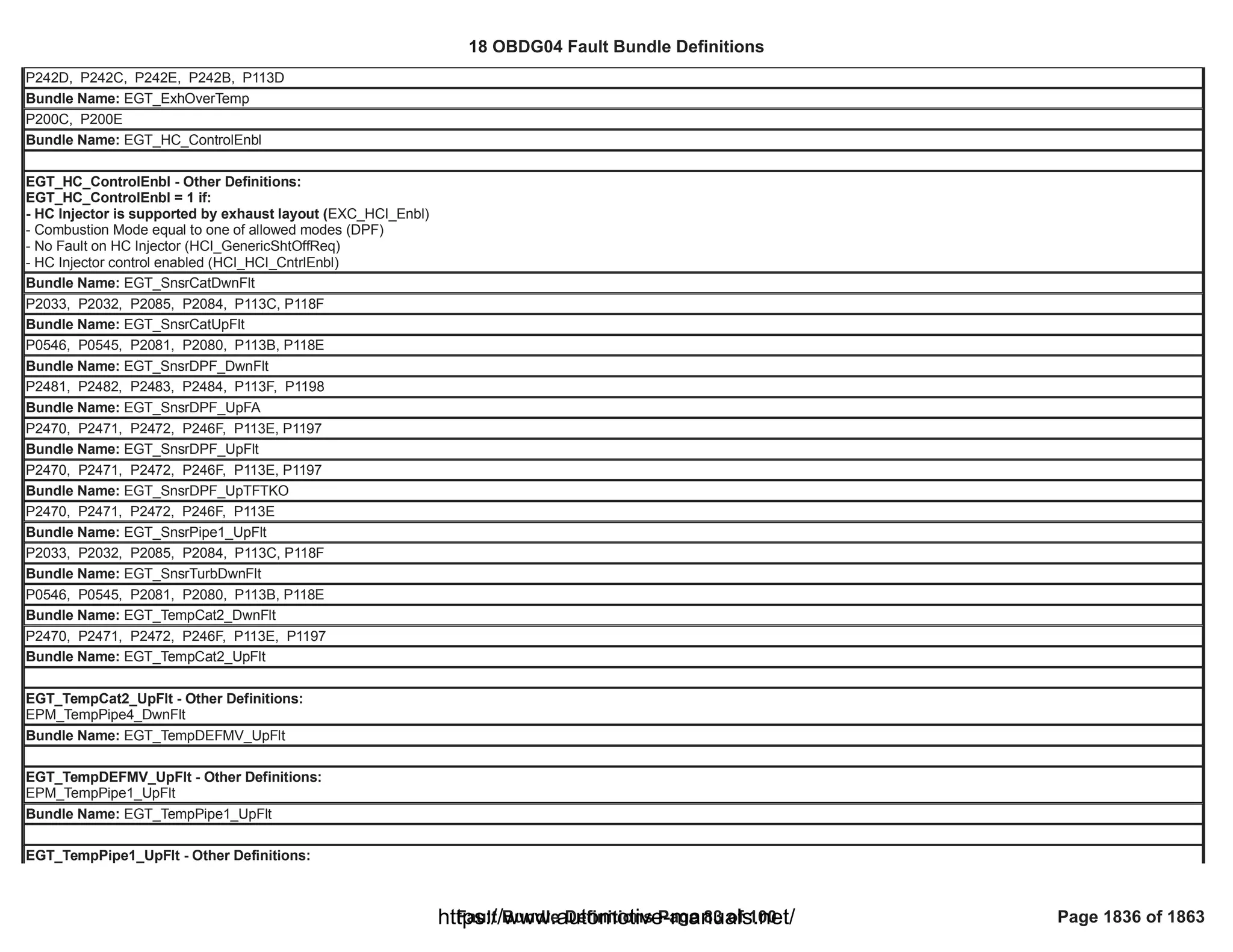
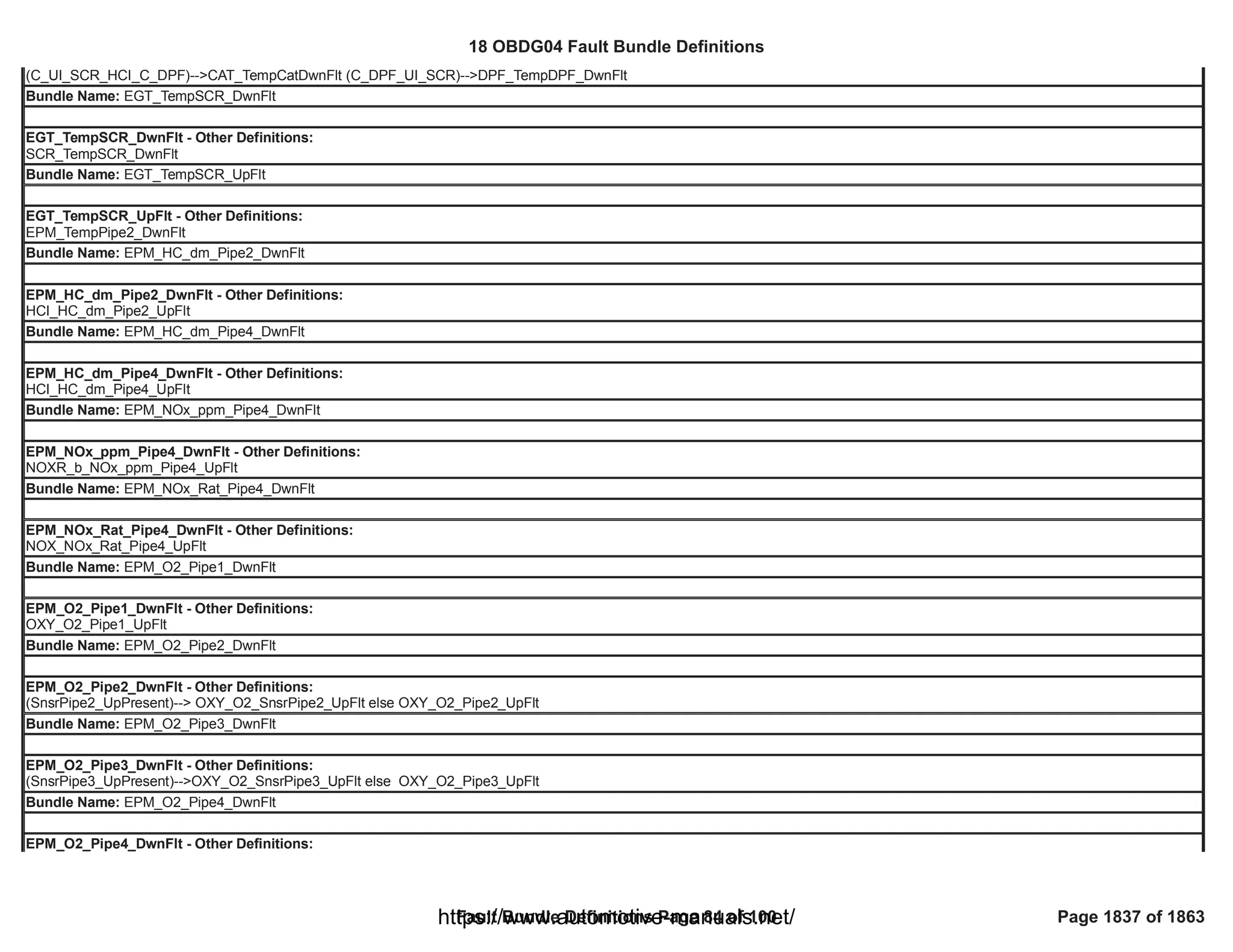
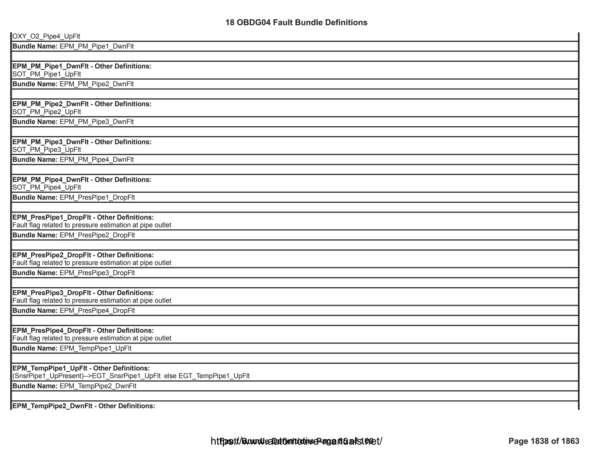
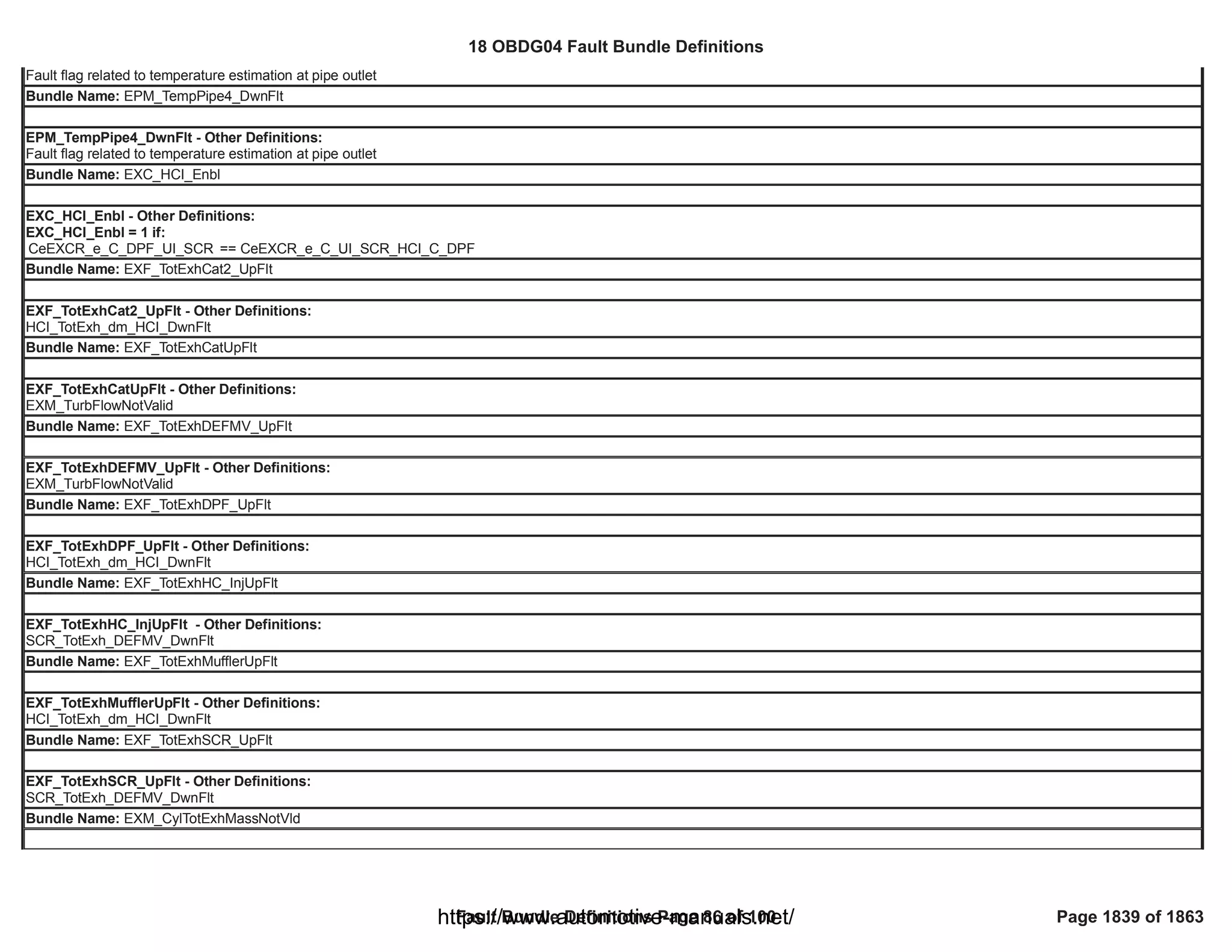
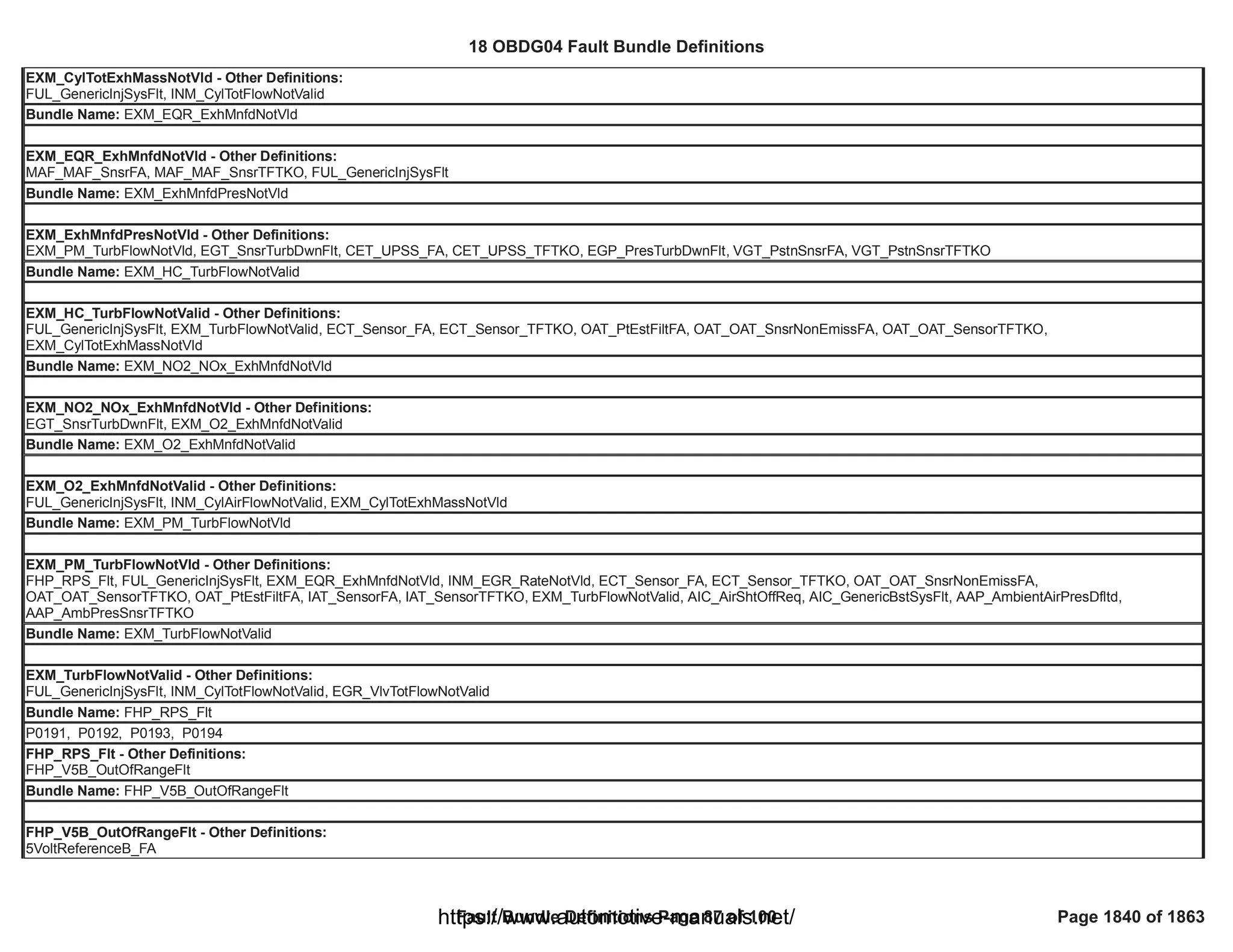
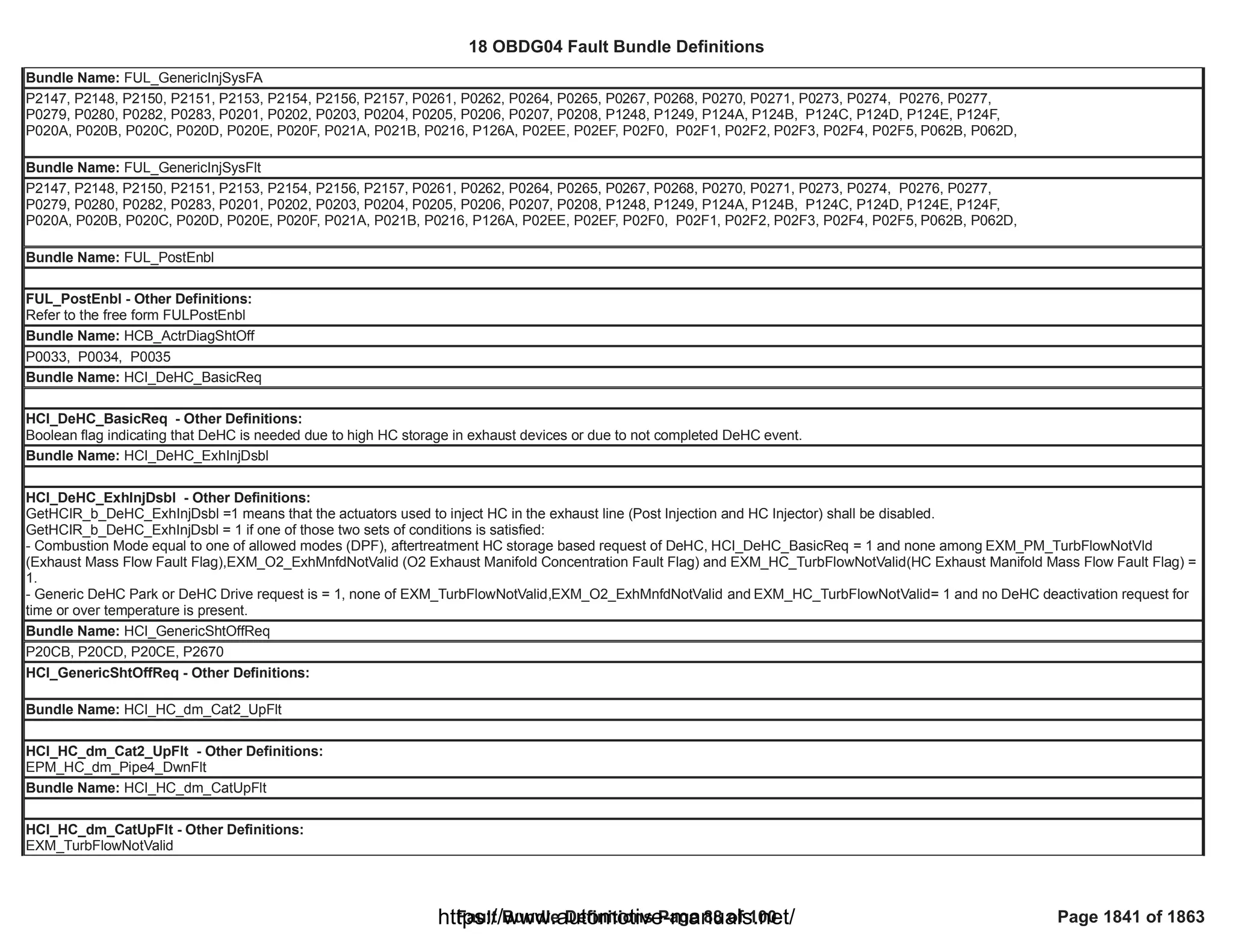
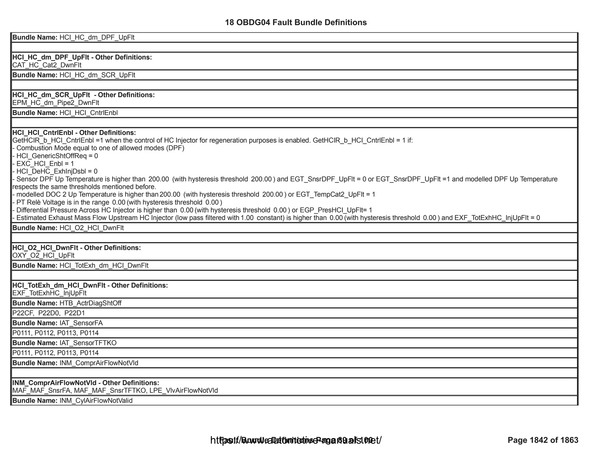
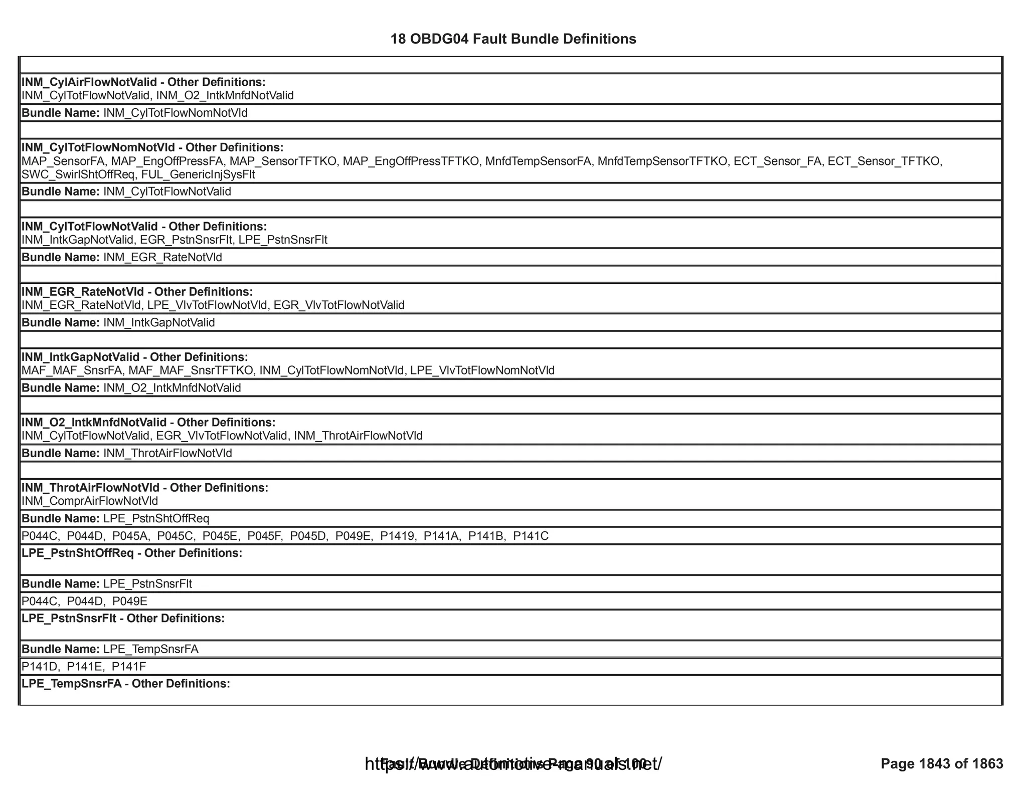
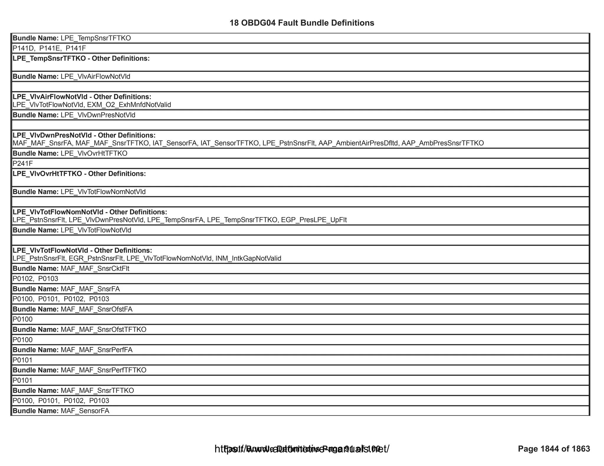
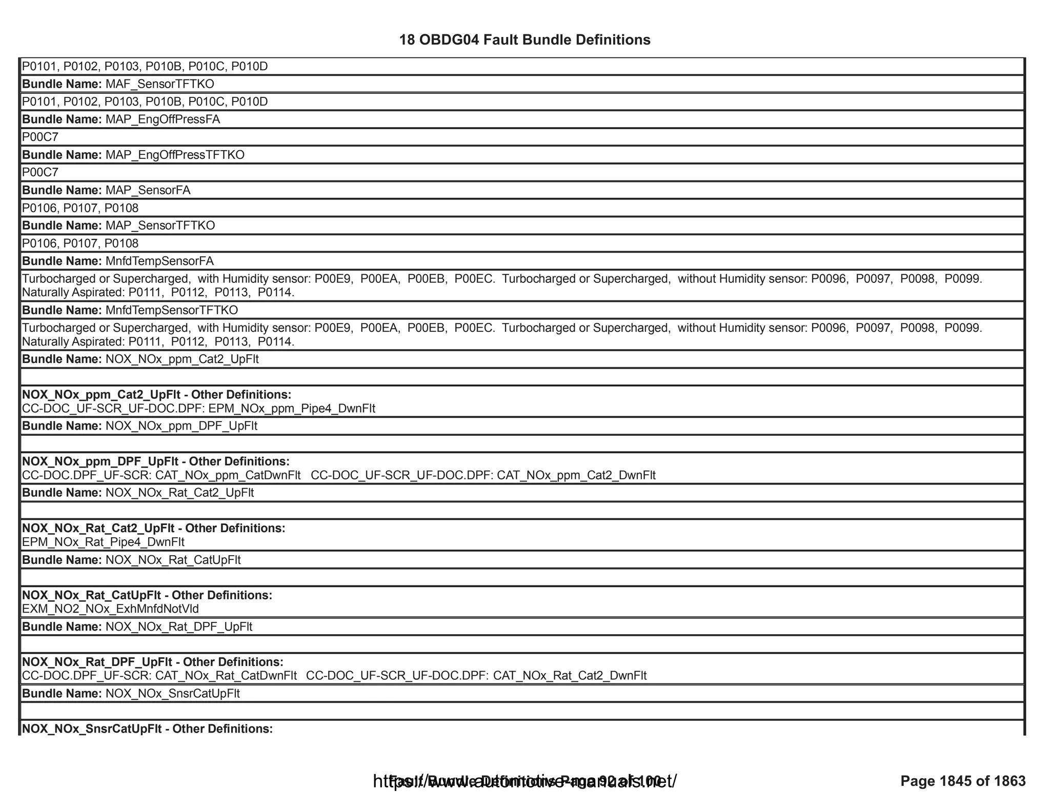
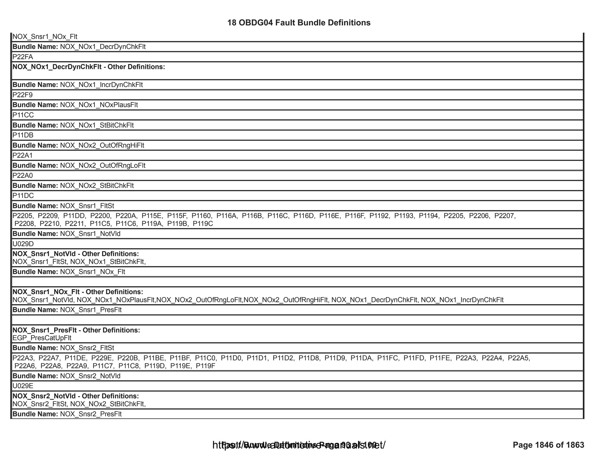
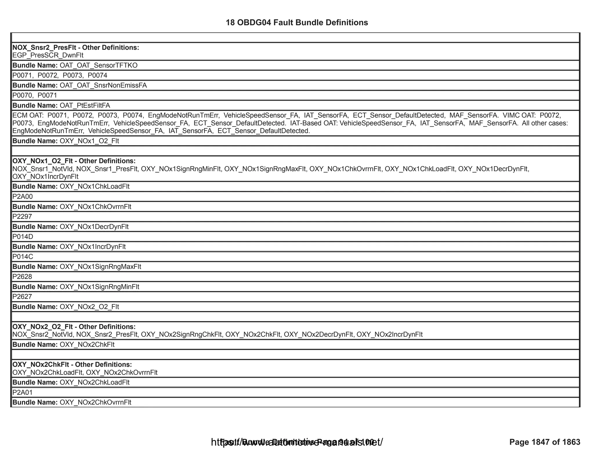
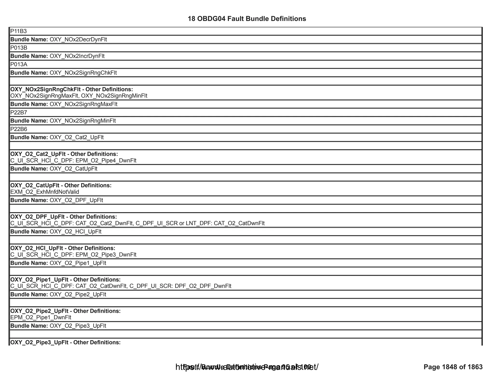
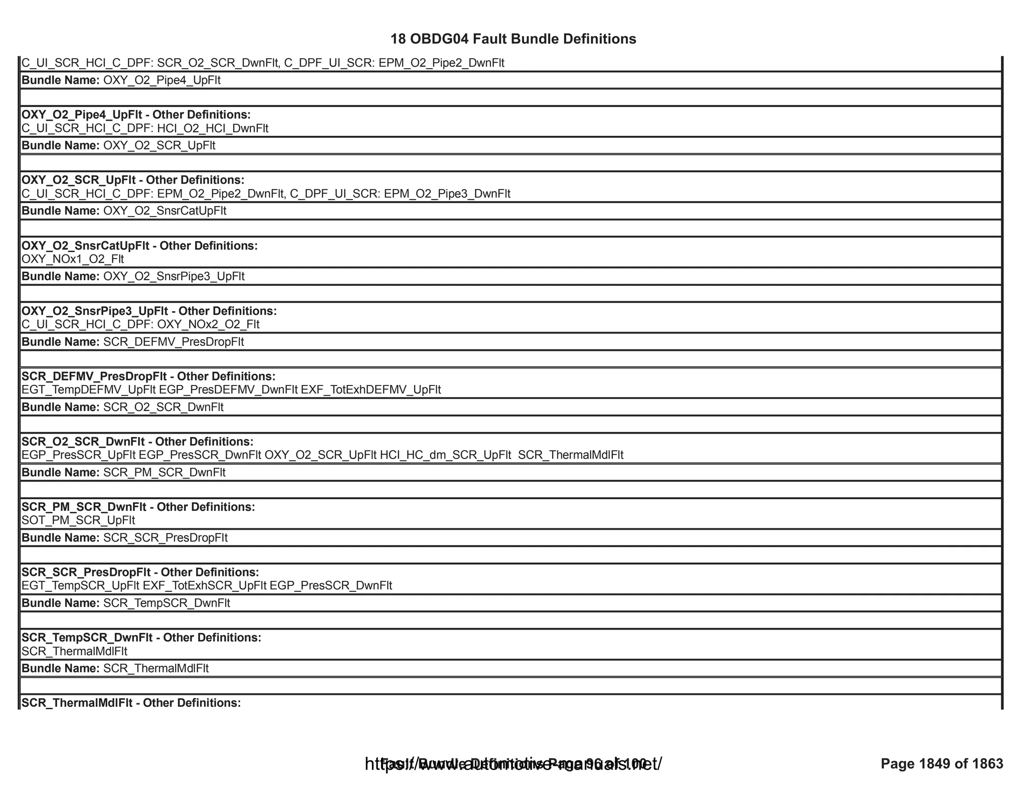
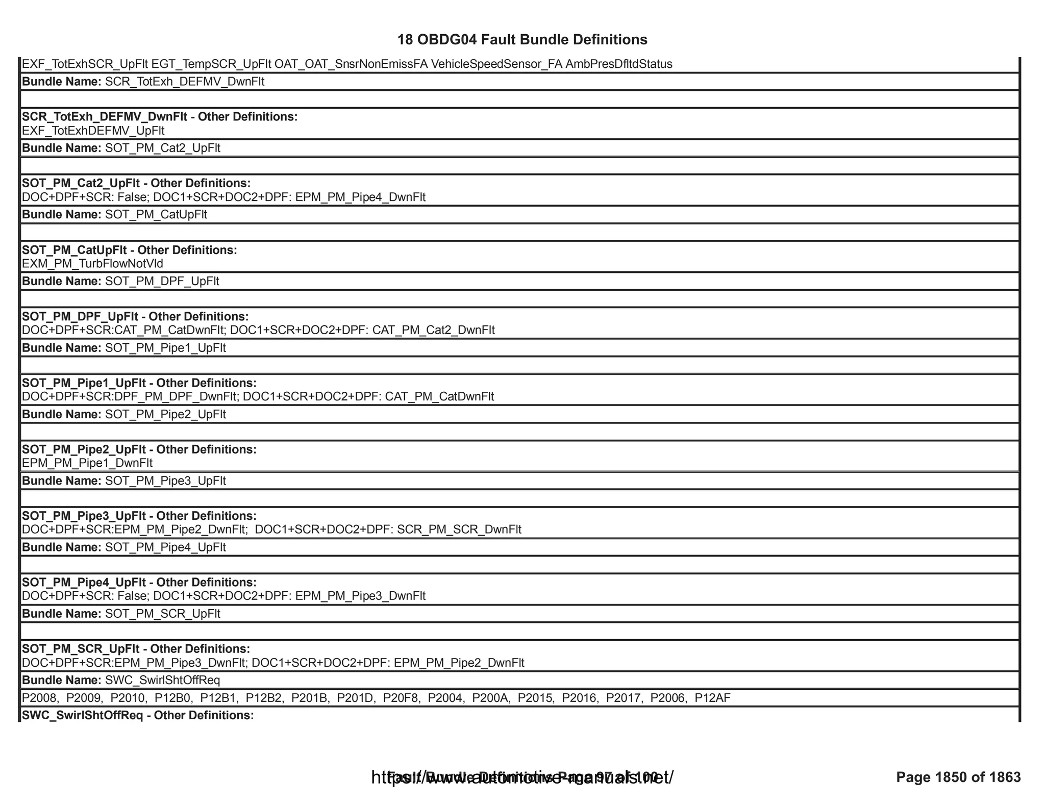
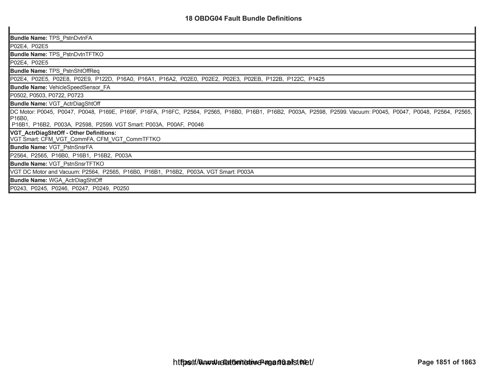
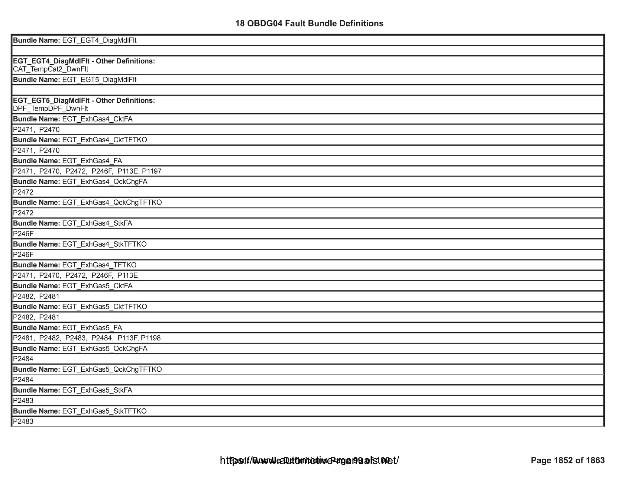
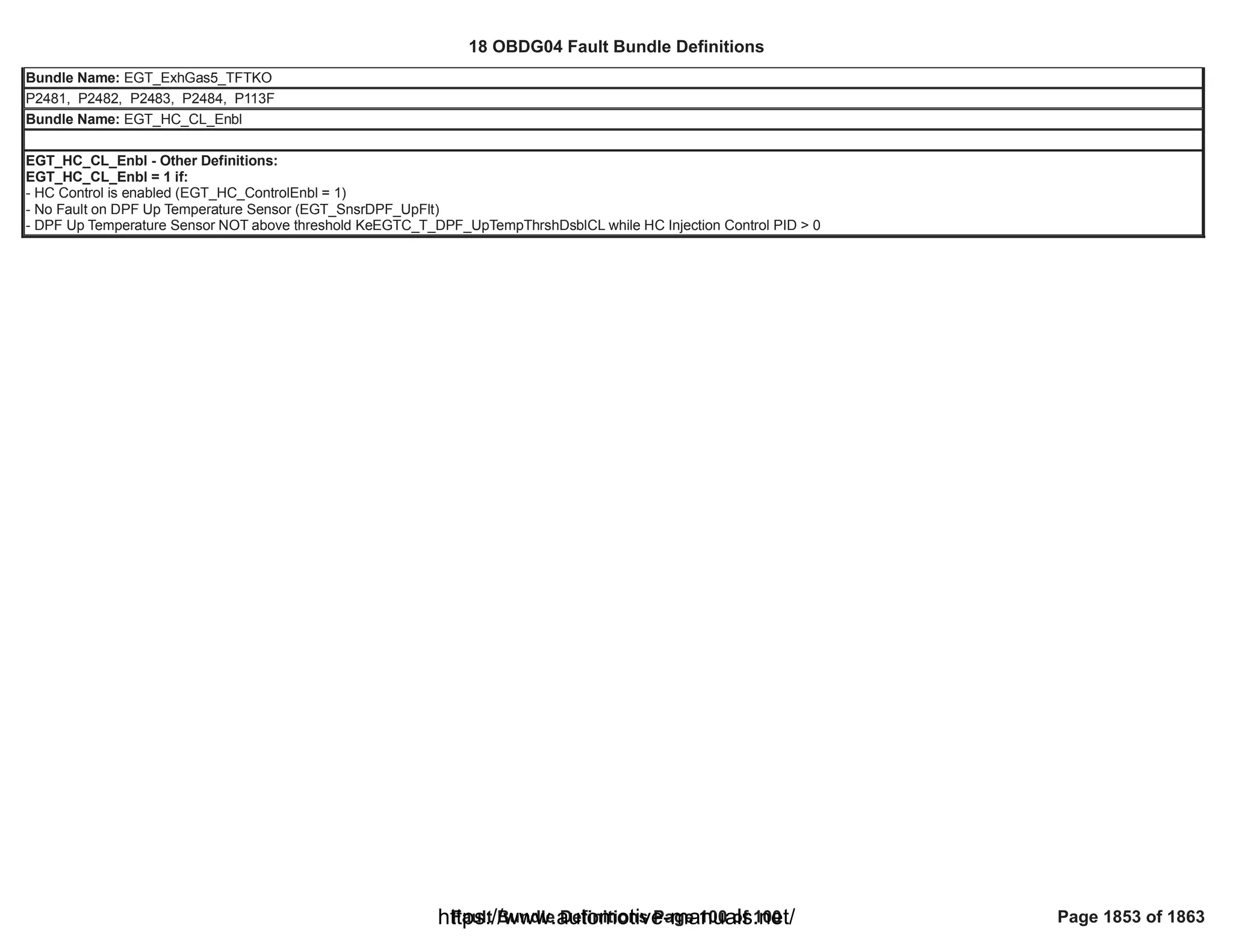
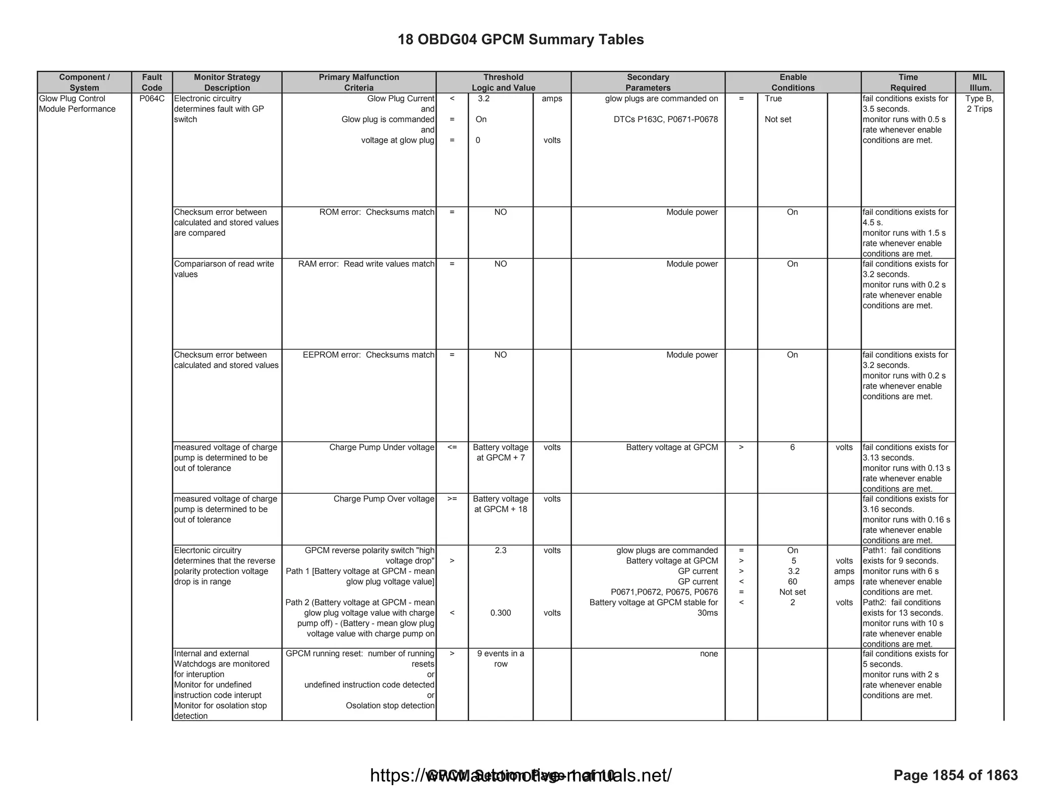
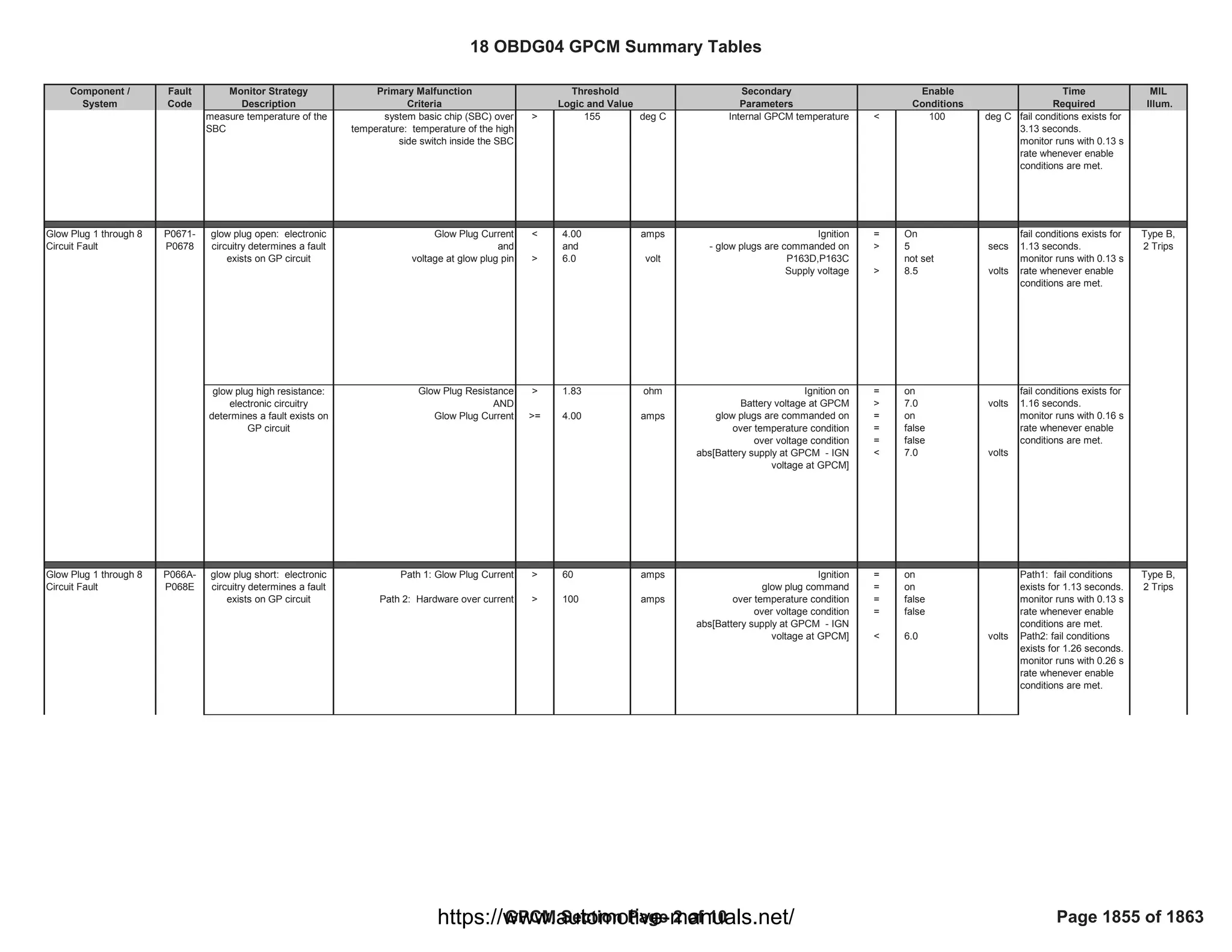
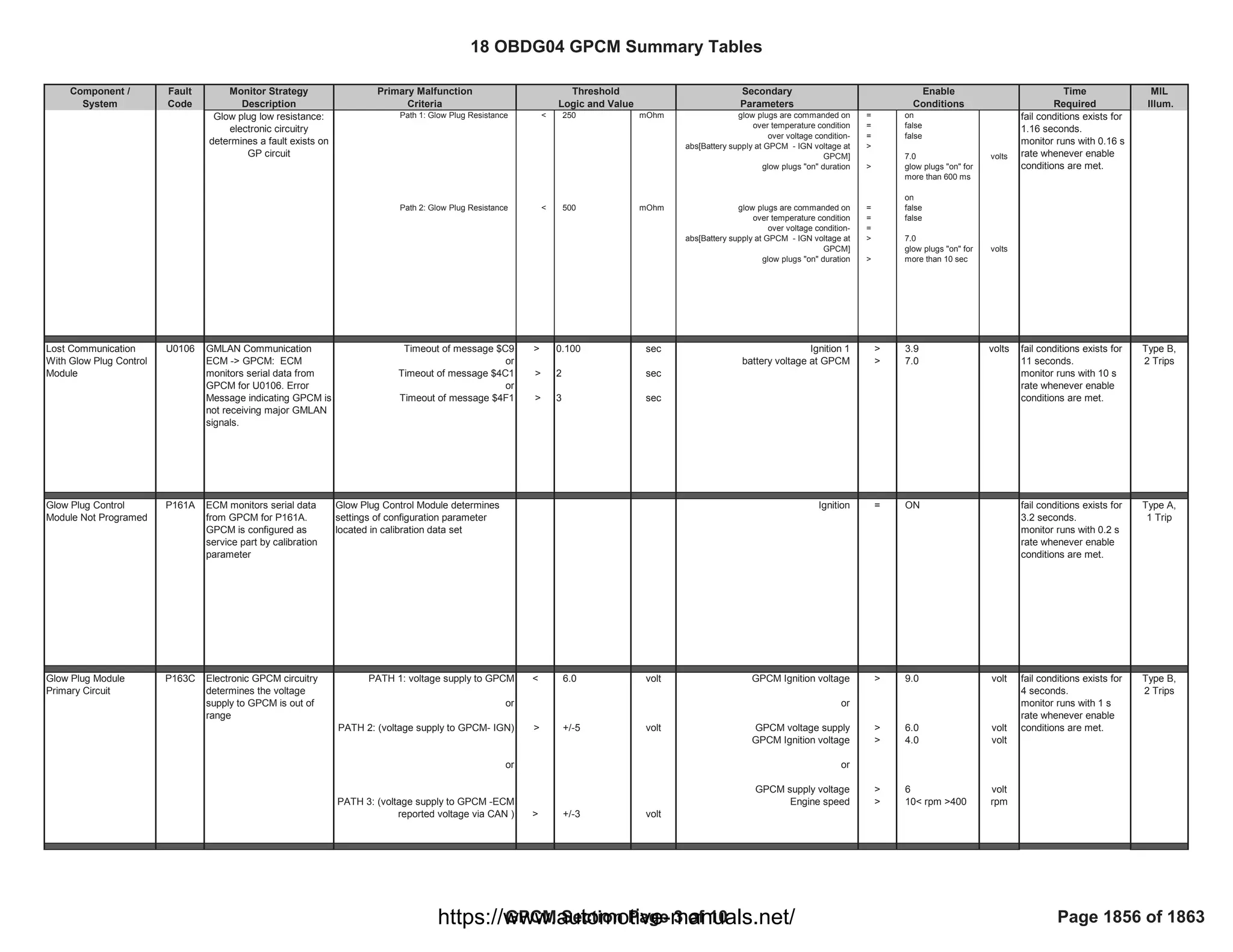
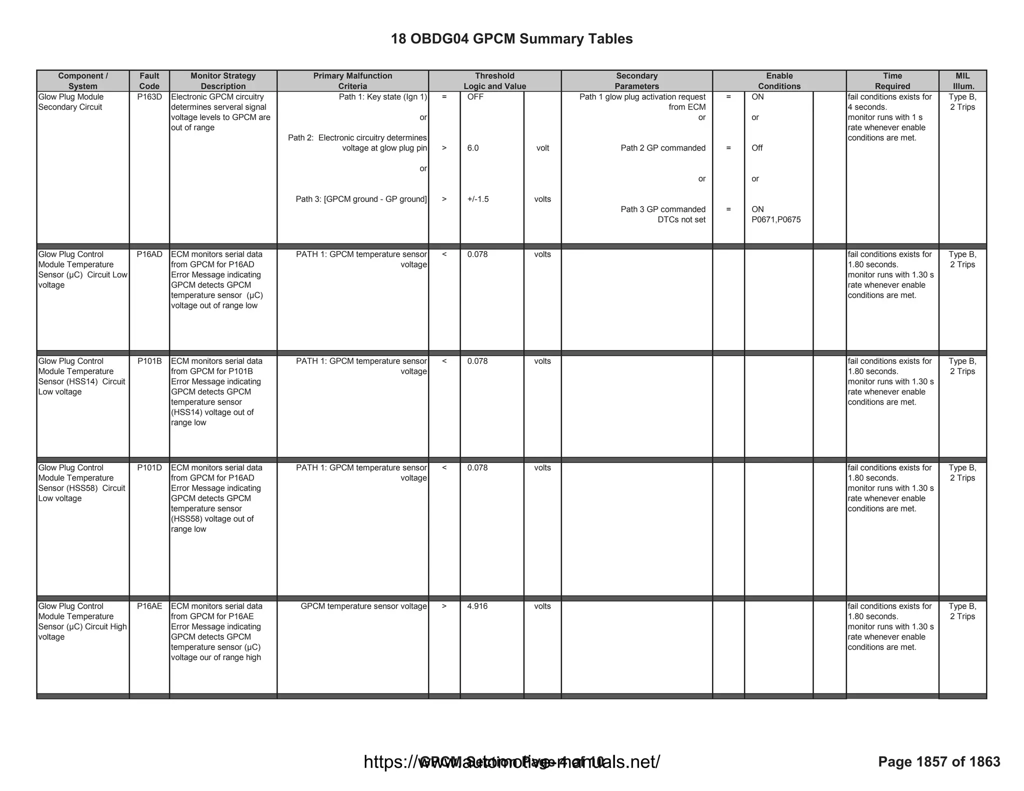
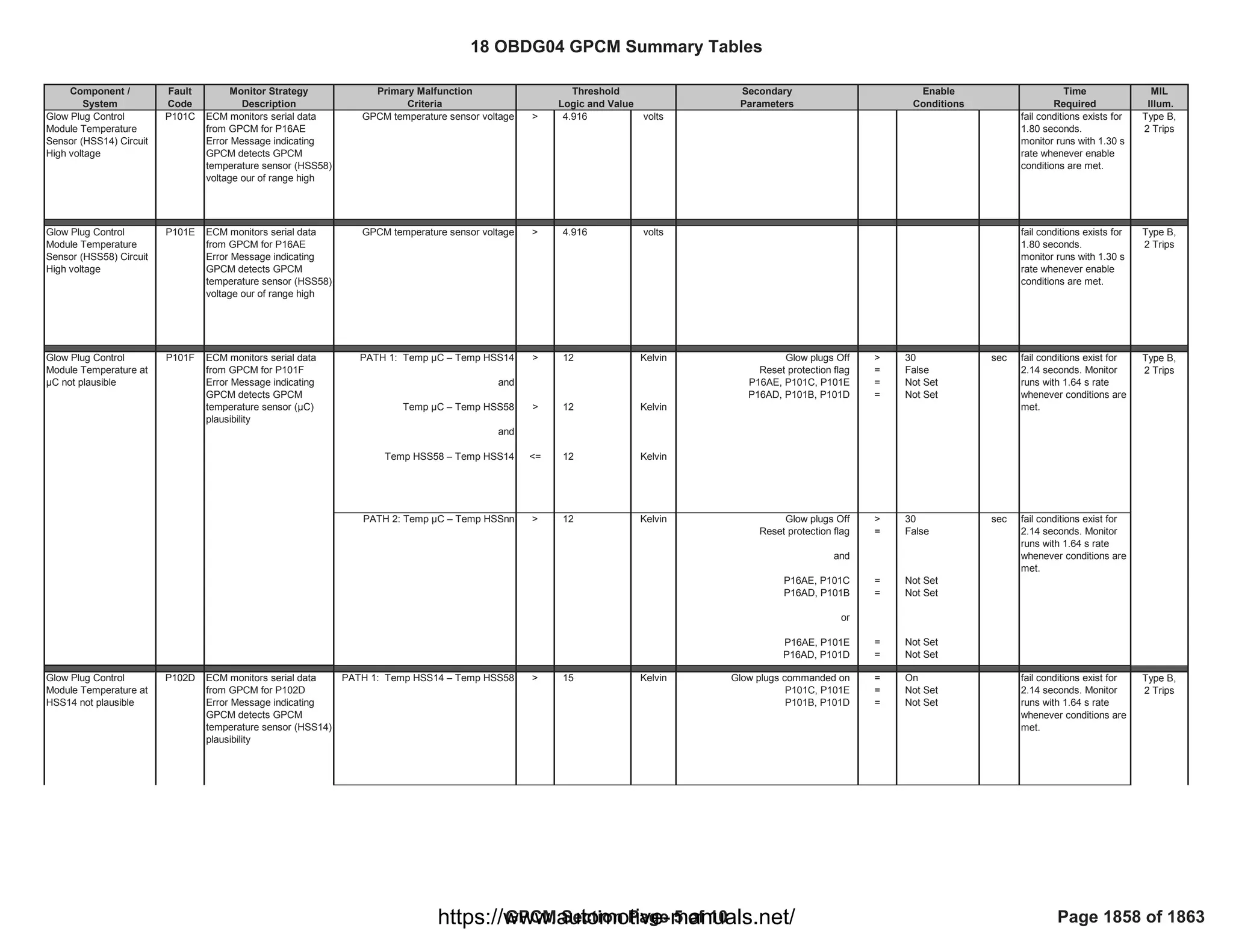
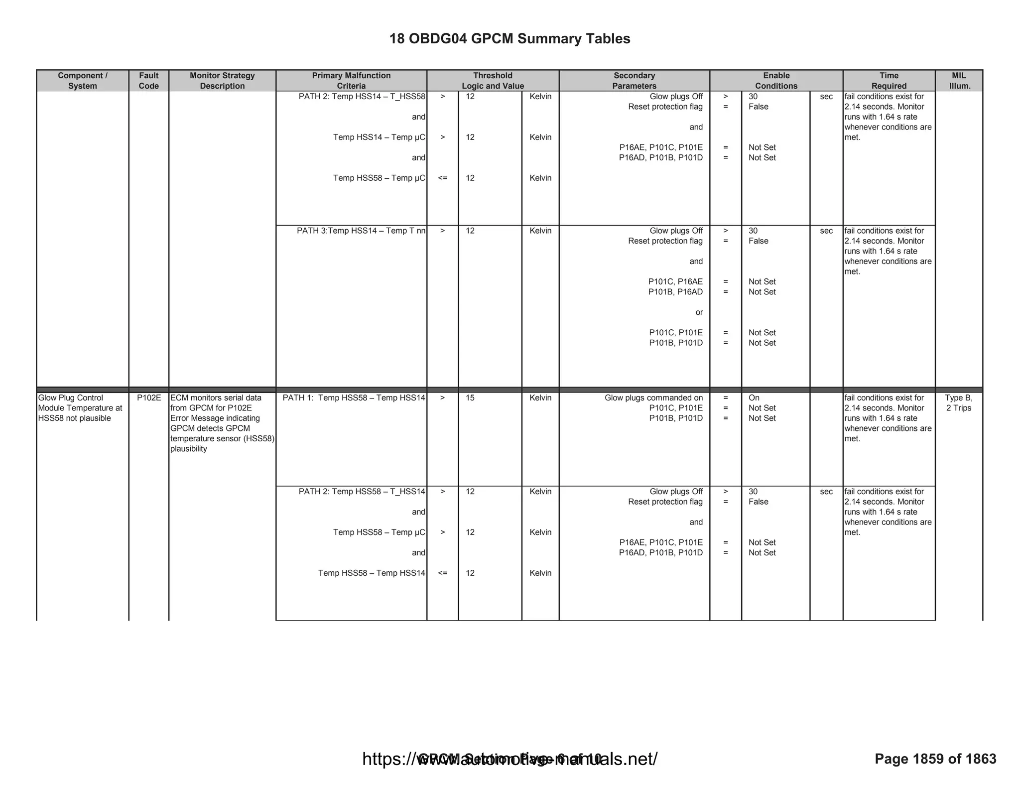
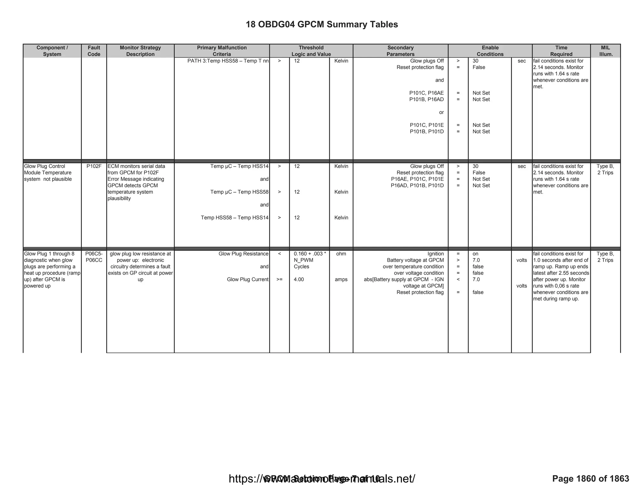
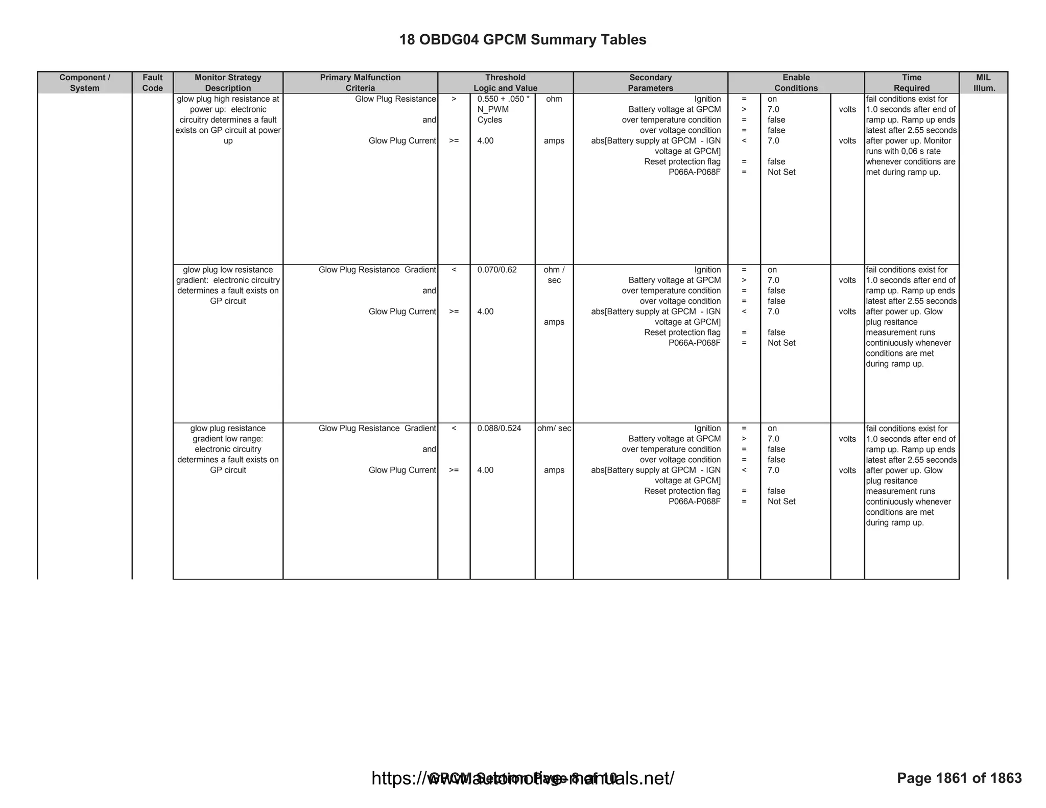
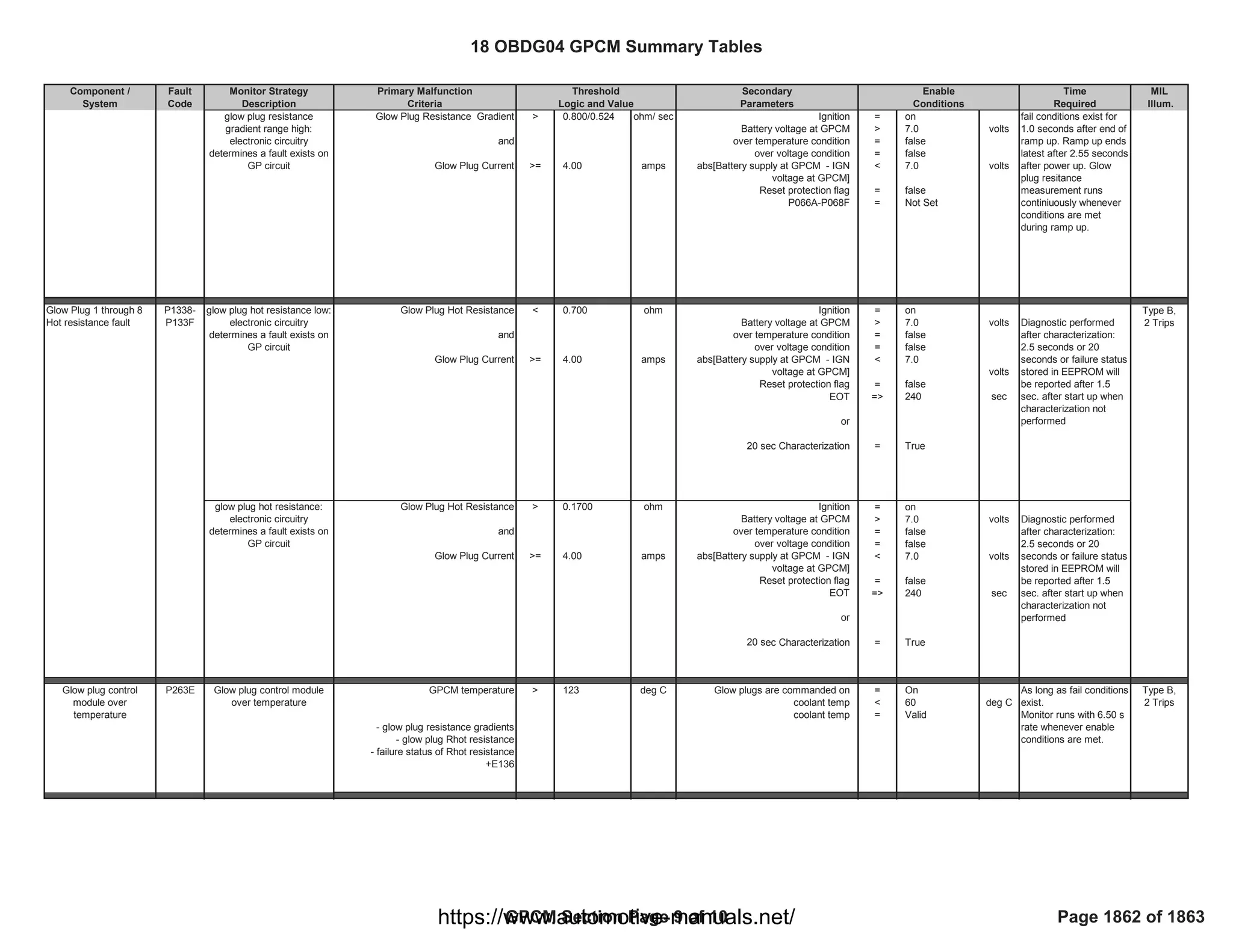
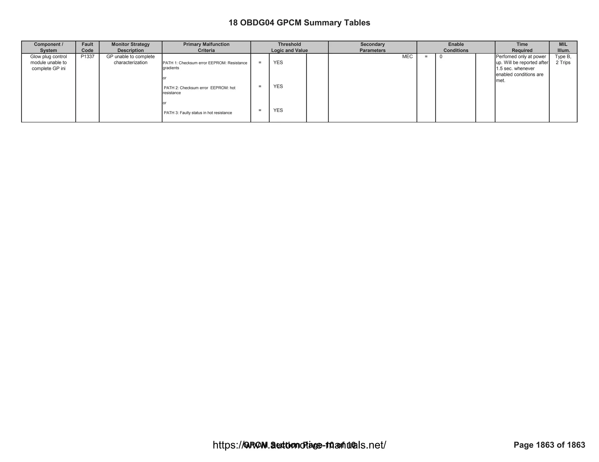

The document describes the monitor strategy for several fault codes related to the heater coolant pump control circuit and the crankshaft position-camshaft position correlation. It provides the fault code, monitor strategy description, malfunction criteria, threshold values, secondary parameters, enable conditions, time required, and MIL illumination for each.