SlideShare a Scribd company logo
1 of 35
| CLASS-A SURFACE DEVELOPMENT + MATURATION METHODS0
Nick Boyd
Product Design Engineer
05.18.2016
INTEGRATED SURFACE /SOLID MODELING DEMONSTRATION
| CLASS-A SURFACE DEVELOPMENT + MATURATION METHODS1
This document provides an overview of the creation and maturation of an Audi R8’s Class-A surfacing. The
intent of the exercise was to represent the finalized styling in a manner consistent with the vehicle’s
character curves and final implementation performed in a manner congruent for further development.
A. INITIAL SETUP
1. GEOMETRIC DATA ORGANIZATION
2. MASTER MODEL
3. CONTROL + CHARACTER CURVES
4. PARTING LINES
B. FUNCTIONAL ASSEMBLIES
5. FRONT BODY
6. MIDDLE BODY
7. DOOR + SIDE ACCENT
8. REAR BODY
9. REAR BUMPER
10. HEADLIGHT
11. GRILLE
12. WHEEL + TIRE
C. FINAL PRODUCT
11. PERSPECTIVE VIEW
12. SIDE VIEW
13. TOP VIEW
14. SUMMARY
OVERVIEW|PRESENTATION ORGANIZATION
| CLASS-A SURFACE DEVELOPMENT + MATURATION METHODS2
A high degree of thought was given towards a consistent organization of 2-D and 3-D data.
Separation of Inputs, Construction and Outputs allows for ease in the surface development
and final refinement form.
Geometrical Set Flow
INITIAL SETUP|GEOMETRIC DATA ORGANIZATION
| CLASS-A SURFACE DEVELOPMENT + MATURATION METHODS3
INITIAL SETUP|MASTER MODEL
The major focus of the project was to replicate the design of the Audi R8 with attention
to a logical and properly constrained workflow. First steps included the precise alignment
of isometric projections in order to develop 3-D curves.
| CLASS-A SURFACE DEVELOPMENT + MATURATION METHODS4
Surface construction began with Control and Character Curves. 3-D curves were
generated through the Combine function and adjusted for appropriate surface
termination and blending with adjacent geometry.
INITIAL SETUP|CONTROL + CHARACTER CURVES
| CLASS-A SURFACE DEVELOPMENT + MATURATION METHODS5
To create surfacing in a development-ready manner, surfaces were created that reproduced
body panel break lines. This would allow for cohesion of functional assembly region of the
car through the splitting of a “master” surface.
INITIAL SETUP|PARTING LINES
| CLASS-A SURFACE DEVELOPMENT + MATURATION METHODS6
Significant focus was brought on reproducing surface relation and terminations as
accurately as possible to reality. Addition of splitting lines and filleting represent a
final product with discrete component characteristics.
FRONT BODY ASSEMBLY| OVERVIEW
| CLASS-A SURFACE DEVELOPMENT + MATURATION METHODS7
Beginning stages of the surfacing process began with creation of Fills, Multi-Sections
and Sweeps that are subsequently trimmed together. Continuity and Tension
parameters were adjusted to capture character of reference form.
FRONT BODY ASSEMBLY|SURFACE DEVELOPMENT
 SIDE PROFILE DEVELOPMENT:
 FENDER TRANSITION AND BLENDING:
+
| CLASS-A SURFACE DEVELOPMENT + MATURATION METHODS8
Development continues with the repetition of additional sketches, surfaces and
trimmed surfaces being incorporated into the model. Discrete components of the
overall assembly are framed-out and begin to take shape.
FRONT BODY ASSEMBLY|SURFACE DEVELOPMENT
 FENDER SURFACE REFINEMENT:
 HEADLIGHT DEFINITION:
| CLASS-A SURFACE DEVELOPMENT + MATURATION METHODS9
The assembly progressed towards its final form, including the definition of discrete
components. Additions such as filets developed the form while maintaining the
original path of the character curves.
FRONT BODY ASSEMBLY|SURFACE DEVELOPMENT
 APERTURE PROFILES:
 BODY PANEL SPLIT + OFFSET:
+
| CLASS-A SURFACE DEVELOPMENT + MATURATION METHODS10
Final touches to this geometry region included the addition of surfaces giving the
outer skin the “dimensionality” of a pre-production product ready for refinement.
This logic is repeated in other major assemblies for consistency.
FRONT BODY ASSEMBLY|SURFACE DEVELOPMENT
 SPLIT + FILET:
 TRANSLATE + TRIM + FILET REFINEMENT:
+
+ +
| CLASS-A SURFACE DEVELOPMENT + MATURATION METHODS11
This surfacing group was the basis for the majority of side and rear components. As with
the master surface, it was important to develop an initial and congruent form from which
further refinement could be performed to obtain discrete components.
MIDDLE BODY ASSEMBLY|OVERVIEW
| CLASS-A SURFACE DEVELOPMENT + MATURATION METHODS12
Initial surfacing began with the roof area of the car and transitions to both the side and the
rear design elements. Base surfaces where utilized in conjunction with parting surfaces in
order to ensure continuity of form.
MIDDLE BODY ASSEMBLY|SURFACE DEVELOPMENT
 SPLIT + FILET:
 TRANSLATE + TRIM + FILET REFINEMENT:
| CLASS-A SURFACE DEVELOPMENT + MATURATION METHODS13
MIDDLE BODY ASSEMBLY|SURFACE DEVELOPMENT
 SPLIT + FILET:
 TRANSLATE + TRIM + FILET REFINEMENT:
Refinement of this assembly’s elements continues to be performed. Special attention was
focused on the transition zone to the rear wheel well where complex geometry exists.
Several rounds of surface creation, trimming and surface re-creation were utilized.
| CLASS-A SURFACE DEVELOPMENT + MATURATION METHODS14
DOORS + SIDE ACCENT ASSEMBLY|OVERVIEW
These elements were derived from the aforementioned Middle Body Assembly, this
allowed for ensuring that the profile and sectioning of the model were consisted with the
reference model. Additions such as the window and mirror provided added dimension.
| CLASS-A SURFACE DEVELOPMENT + MATURATION METHODS15
DOOR + SIDE ACCENT ASSEMBLY|SURFACE DEVELOPMENT
 SPLIT + FILET:
 TRANSLATE + TRIM + FILET REFINEMENT:
Geometry in this section utilized the offsetting of source surfaces in order to create both
apertures and further general styling cues. Integration of the mirror and handle elements
were complex entities and took many refinements to maintain accuracy.
| CLASS-A SURFACE DEVELOPMENT + MATURATION METHODS16
DOOR + SIDE ACCENT ASSEMBLY|SURFACE DEVELOPMENT
 SPLIT + FILET:
 TRANSLATE + TRIM + FILET REFINEMENT:
Further utilization of apertures and integration of character curves drove the
developments of the door element further into more complex forms. Implement this
standard geometry architecture allowed for the refinement of the side accent.
| CLASS-A SURFACE DEVELOPMENT + MATURATION METHODS17
REAR BODY ASSEMBLY|OVERVIEW
The Middle Body again presented itself in this geometry area with the integration of body
panels, accent features and those with optical properties. This was another very complex
area that required many iterations of surfacing to deliver an accurate result.
| CLASS-A SURFACE DEVELOPMENT + MATURATION METHODS18
REAR BODY ASSEMBLY|SURFACE DEVELOPMENT
 SPLIT + FILET:
 TRANSLATE + TRIM + FILET REFINEMENT:
Integration of parting surfaces were the focal point of the initial surfacing refinement. Of
special attention in this process was the sub-division of existing surfaces, extraction of
reference edges and tension/continuity tuning of transitional zones.
| CLASS-A SURFACE DEVELOPMENT + MATURATION METHODS19
REAR BODY ASSEMBLY|SURFACE DEVELOPMENT
 SPLIT + FILET:
 TRANSLATE + TRIM + FILET REFINEMENT:
Discrete components of this assembly became more refine and defined in this stage of the
development process. The original character curves were again utilized to maintain a
continuity of form throughout the final product.
| CLASS-A SURFACE DEVELOPMENT + MATURATION METHODS20
REAR BUMPER ASSEMBLY|OVERVIEW
This section is a further refinement of the Middle Body and contained a multitude of
surfacing interaction as this area is complex in its geometry. The addition of solid part
modeling was also incorporated in the development of the exhaust components.
| CLASS-A SURFACE DEVELOPMENT + MATURATION METHODS21
REAR BUMPER ASSEMBLY|SURFACE DEVELOPMENT
 SPLIT + FILET:
 TRANSLATE + TRIM + FILET REFINEMENT:
Development in this area was highly dependent on its surrounding surfacing to develop
the general form. In addition, numerous unique surfaces where incorporated into the
geometry giving complex styling characteristics.
| CLASS-A SURFACE DEVELOPMENT + MATURATION METHODS22
REAR BUMPER ASSEMBLY|SURFACE DEVELOPMENT
 SPLIT + FILET:
 TRANSLATE + TRIM + FILET REFINEMENT:
Depiction of further refinements to the assembly form were once again driven by the
importance of replicating the reference form as closely as possible. Elements such as the
rear splitter and exhaust packaging were integrated accordingly.
| CLASS-A SURFACE DEVELOPMENT + MATURATION METHODS23
REAR BUMPER ASSEMBLY|SURFACE DEVELOPMENT
 SPLIT + FILET:
 TRANSLATE + TRIM + FILET REFINEMENT:
Final stages of this area’s development included the definition of the rear bumper sections
separated by material application. A parting surface the was utilized in previous assemblies
was applied here in order to further maintain form continuity.
| CLASS-A SURFACE DEVELOPMENT + MATURATION METHODS24
HEADLIGHT ASSEMBLY|OVERVIEW
These elements were developed to display design intent of this assembly area. As the
optical properties of a headlight are extremely complex, the approach with this area was
to refine the geometry without over-complication of the final form.
| CLASS-A SURFACE DEVELOPMENT + MATURATION METHODS25
HEADLIGHT ASSEMBLY|SURFACE DEVELOPMENT
 SPLIT + FILET:
 TRANSLATE + TRIM + FILET REFINEMENT:
Refined surfaces from the front body assembly were combined with aperture definitions
to resolve the headlight and surrounding geometry. Solid body modeling was utilized to
develop the styling below the headlight lens representation.
| CLASS-A SURFACE DEVELOPMENT + MATURATION METHODS26
GRILLE ASSEMBLY|OVERVIEW
Development of this section was unique in the fact that the majority of its construction
was done through Solid Part design. Utilization of feature patterning and mirroring
techniques that allowed for expedited completion.
| CLASS-A SURFACE DEVELOPMENT + MATURATION METHODS27
GRILLE ASSEMBLY|SURFACE + SOLID DEVELOPMENT
 SPLIT + FILET:
 TRANSLATE + TRIM + FILET REFINEMENT:
Surface design was the initial driving method for form development – specifically
previously used Parting Surfaces. After this boundary definition, solid components were
integrated to complete the refinement process.
| CLASS-A SURFACE DEVELOPMENT + MATURATION METHODS28
WHEEL + TIRE ASSEMBLY|OVERVIEW
Construction of this element presented another blending of Surface and Solids modeling.
Patterning of cutting forms was critical in the development of both tire and wheel forms as
can be observed in their final characteristics.
| CLASS-A SURFACE DEVELOPMENT + MATURATION METHODS29
WHEEL + TIRE ASSEMBLY|SURFACE + SOLID DEVELOPMENT
 SPLIT + FILET:
 TRANSLATE + TRIM + FILET REFINEMENT:
Development of the wheel began simplistically and grew in complexity rapidly through the
implementation of the Pattern feature. This approach allowed for a detailed model to be
constructed in an efficient and easily updatable format.
| CLASS-A SURFACE DEVELOPMENT + MATURATION METHODS30
WHEEL + TIRE ASSEMBLY|SURFACE + SOLID DEVELOPMENT
 SPLIT + FILET:
 TRANSLATE + TRIM + FILET REFINEMENT:
The Tire maturation process also used the Pattern feature in order to drive the tread
creation process. As actual tread patters are highly complex and functionally designed, the
intent of this model was to provide a close approximation of the reference form.
| CLASS-A SURFACE DEVELOPMENT + MATURATION METHODS31
FINAL PRODUCT|PERSPECTIVE VIEW
Surface construction began with “Control” Character Curves. 3-D curves were generated
through the Combine function and adjusted for appropriate surface termination and
blending with adjacent geometry.
| CLASS-A SURFACE DEVELOPMENT + MATURATION METHODS32
FINAL PRODUCT|SIDE VIEW
Surface construction began with “Control” Character Curves. 3-D curves were generated
through the Combine function and adjusted for appropriate surface termination and
blending with adjacent geometry.
| CLASS-A SURFACE DEVELOPMENT + MATURATION METHODS33
FINAL PRODUCT|TOP VIEW
Surface construction began with “Control” Character Curves. 3-D curves were generated
through the Combine function and adjusted for appropriate surface termination and
blending with adjacent geometry.
| CLASS-A SURFACE DEVELOPMENT + MATURATION METHODS34
FINAL PRODUCT|SUMMARY
Surface construction began with “Control” Character Curves. 3-D curves were generated
through the Combine function and adjusted for appropriate surface termination and
blending with adjacent geometry.

More Related Content

What's hot

Gearbox Design Team1-4_Project4
Gearbox Design Team1-4_Project4Gearbox Design Team1-4_Project4
Gearbox Design Team1-4_Project4
Trent Hosokawa
 
Basic gd&t datums
Basic gd&t   datumsBasic gd&t   datums
Basic gd&t datums
mjferrari76
 

What's hot (20)

Vehicle body
Vehicle bodyVehicle body
Vehicle body
 
Unit 5-cad standards
Unit 5-cad standardsUnit 5-cad standards
Unit 5-cad standards
 
Jigs & Fixtures
Jigs & Fixtures Jigs & Fixtures
Jigs & Fixtures
 
GD&T for Omega Fabrication, Melaka.4-5th March 2017
GD&T for Omega Fabrication, Melaka.4-5th March 2017GD&T for Omega Fabrication, Melaka.4-5th March 2017
GD&T for Omega Fabrication, Melaka.4-5th March 2017
 
gear box - heart of automobile
gear box - heart of automobilegear box - heart of automobile
gear box - heart of automobile
 
Geometric dimensioning and tolerance
Geometric dimensioning and toleranceGeometric dimensioning and tolerance
Geometric dimensioning and tolerance
 
Biw
BiwBiw
Biw
 
Gearbox Design Team1-4_Project4
Gearbox Design Team1-4_Project4Gearbox Design Team1-4_Project4
Gearbox Design Team1-4_Project4
 
Design for Plastics
Design for Plastics Design for Plastics
Design for Plastics
 
Basic gd&t datums
Basic gd&t   datumsBasic gd&t   datums
Basic gd&t datums
 
Tolerance stack up and analysis mn
Tolerance stack up and analysis   mnTolerance stack up and analysis   mn
Tolerance stack up and analysis mn
 
MECH CREO
MECH CREOMECH CREO
MECH CREO
 
Suspension system
Suspension systemSuspension system
Suspension system
 
biw-.pdf
biw-.pdfbiw-.pdf
biw-.pdf
 
Steering
SteeringSteering
Steering
 
Unit 4 helical gear
Unit 4 helical gearUnit 4 helical gear
Unit 4 helical gear
 
Car seat design for driver satisfaction
Car seat design for driver satisfactionCar seat design for driver satisfaction
Car seat design for driver satisfaction
 
Bus body fabrication- Design & Analysis
Bus body fabrication-  Design & AnalysisBus body fabrication-  Design & Analysis
Bus body fabrication- Design & Analysis
 
Vehicle Body Engineering - Introduction
Vehicle Body Engineering - IntroductionVehicle Body Engineering - Introduction
Vehicle Body Engineering - Introduction
 
Spur gear and design of spur gear
Spur gear and design of spur gearSpur gear and design of spur gear
Spur gear and design of spur gear
 

Viewers also liked (11)

CP10847 - Complex Topology and Class-A Surface Modeling with Inventor (Presen...
CP10847 - Complex Topology and Class-A Surface Modeling with Inventor (Presen...CP10847 - Complex Topology and Class-A Surface Modeling with Inventor (Presen...
CP10847 - Complex Topology and Class-A Surface Modeling with Inventor (Presen...
 
Finite Element Analysis / CAE Portfolio
Finite Element Analysis / CAE PortfolioFinite Element Analysis / CAE Portfolio
Finite Element Analysis / CAE Portfolio
 
Image 2 Torrent 발표자료
Image 2 Torrent 발표자료Image 2 Torrent 발표자료
Image 2 Torrent 발표자료
 
Design Engineering Portfolio
Design Engineering PortfolioDesign Engineering Portfolio
Design Engineering Portfolio
 
scc2015-release-of-sfe-baumeister
scc2015-release-of-sfe-baumeisterscc2015-release-of-sfe-baumeister
scc2015-release-of-sfe-baumeister
 
Production and Operations Management
Production and Operations ManagementProduction and Operations Management
Production and Operations Management
 
Dubai
DubaiDubai
Dubai
 
Final Intern Presentation
Final Intern PresentationFinal Intern Presentation
Final Intern Presentation
 
Tata NANO
Tata NANOTata NANO
Tata NANO
 
Using 3-D Seismic Attributes in Reservoir Characterization
Using 3-D Seismic Attributes in Reservoir CharacterizationUsing 3-D Seismic Attributes in Reservoir Characterization
Using 3-D Seismic Attributes in Reservoir Characterization
 
Shell structures- advanced building construction
Shell structures- advanced building constructionShell structures- advanced building construction
Shell structures- advanced building construction
 

Similar to Class-A Surface Development + Maturation Methods

FINAL SUBMISSION project - Copy (1)
FINAL SUBMISSION project - Copy (1)FINAL SUBMISSION project - Copy (1)
FINAL SUBMISSION project - Copy (1)
Amit Jain
 

Similar to Class-A Surface Development + Maturation Methods (20)

FINAL SUBMISSION project - Copy (1)
FINAL SUBMISSION project - Copy (1)FINAL SUBMISSION project - Copy (1)
FINAL SUBMISSION project - Copy (1)
 
CFD Best Practices and Troubleshooting - with speaker notes
CFD Best Practices and Troubleshooting - with speaker notesCFD Best Practices and Troubleshooting - with speaker notes
CFD Best Practices and Troubleshooting - with speaker notes
 
Topology Optimization of Student Car Steering Knuckle
Topology Optimization of Student Car Steering KnuckleTopology Optimization of Student Car Steering Knuckle
Topology Optimization of Student Car Steering Knuckle
 
Drag Reduction of Front Wing of an F1 Car using Adjoint Optimisation
Drag Reduction of Front Wing of an F1 Car using Adjoint OptimisationDrag Reduction of Front Wing of an F1 Car using Adjoint Optimisation
Drag Reduction of Front Wing of an F1 Car using Adjoint Optimisation
 
IRJET- CFD-A Trend in Automobile Aerodynamics Technology
IRJET- 	  CFD-A Trend in Automobile Aerodynamics TechnologyIRJET- 	  CFD-A Trend in Automobile Aerodynamics Technology
IRJET- CFD-A Trend in Automobile Aerodynamics Technology
 
Convert machined surfaces to plateaued surf
Convert machined surfaces to plateaued surfConvert machined surfaces to plateaued surf
Convert machined surfaces to plateaued surf
 
77201903
7720190377201903
77201903
 
77201903
7720190377201903
77201903
 
Design Modification for Weight Reduction and Structural Analysis of Automotiv...
Design Modification for Weight Reduction and Structural Analysis of Automotiv...Design Modification for Weight Reduction and Structural Analysis of Automotiv...
Design Modification for Weight Reduction and Structural Analysis of Automotiv...
 
Consequence of Reinforced Concrete Slab Subjected to Blast Load
Consequence of Reinforced Concrete Slab Subjected to Blast LoadConsequence of Reinforced Concrete Slab Subjected to Blast Load
Consequence of Reinforced Concrete Slab Subjected to Blast Load
 
CFD Analysis on Aerodynamic Effects on a Passenger Car
CFD Analysis on Aerodynamic Effects on a Passenger CarCFD Analysis on Aerodynamic Effects on a Passenger Car
CFD Analysis on Aerodynamic Effects on a Passenger Car
 
Investigations of Drag and Lift Forces Over the Profiles of Car Using CFD
Investigations of Drag and Lift Forces Over the Profiles of Car Using CFDInvestigations of Drag and Lift Forces Over the Profiles of Car Using CFD
Investigations of Drag and Lift Forces Over the Profiles of Car Using CFD
 
Topology optimization - Metal Bracket
Topology optimization - Metal BracketTopology optimization - Metal Bracket
Topology optimization - Metal Bracket
 
Performance Study of Wind Friction Reduction Attachments for Van Using Comput...
Performance Study of Wind Friction Reduction Attachments for Van Using Comput...Performance Study of Wind Friction Reduction Attachments for Van Using Comput...
Performance Study of Wind Friction Reduction Attachments for Van Using Comput...
 
Performance Study of Wind Friction Reduction Attachments for Van Using Comput...
Performance Study of Wind Friction Reduction Attachments for Van Using Comput...Performance Study of Wind Friction Reduction Attachments for Van Using Comput...
Performance Study of Wind Friction Reduction Attachments for Van Using Comput...
 
IRJET - Design Modification of Car Bonnet to Reduce the Frictional Drag
IRJET - Design Modification of Car Bonnet to Reduce the Frictional DragIRJET - Design Modification of Car Bonnet to Reduce the Frictional Drag
IRJET - Design Modification of Car Bonnet to Reduce the Frictional Drag
 
Aerodynamic Analysis of Car body with Aerodynamic Devices to Improve Performance
Aerodynamic Analysis of Car body with Aerodynamic Devices to Improve PerformanceAerodynamic Analysis of Car body with Aerodynamic Devices to Improve Performance
Aerodynamic Analysis of Car body with Aerodynamic Devices to Improve Performance
 
Aerodynamic Analysis of Car body with Aerodynamic Devices to Improve Performance
Aerodynamic Analysis of Car body with Aerodynamic Devices to Improve PerformanceAerodynamic Analysis of Car body with Aerodynamic Devices to Improve Performance
Aerodynamic Analysis of Car body with Aerodynamic Devices to Improve Performance
 
Final Year Paper-Designing the 2016 RMIT Aero Package - Hashan Mendis
Final Year Paper-Designing the 2016 RMIT Aero Package - Hashan MendisFinal Year Paper-Designing the 2016 RMIT Aero Package - Hashan Mendis
Final Year Paper-Designing the 2016 RMIT Aero Package - Hashan Mendis
 
Ski-Wing
Ski-WingSki-Wing
Ski-Wing
 

Class-A Surface Development + Maturation Methods

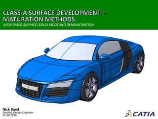
  • 1. | CLASS-A SURFACE DEVELOPMENT + MATURATION METHODS0 Nick Boyd Product Design Engineer 05.18.2016 INTEGRATED SURFACE /SOLID MODELING DEMONSTRATION
  • 2. | CLASS-A SURFACE DEVELOPMENT + MATURATION METHODS1 This document provides an overview of the creation and maturation of an Audi R8’s Class-A surfacing. The intent of the exercise was to represent the finalized styling in a manner consistent with the vehicle’s character curves and final implementation performed in a manner congruent for further development. A. INITIAL SETUP 1. GEOMETRIC DATA ORGANIZATION 2. MASTER MODEL 3. CONTROL + CHARACTER CURVES 4. PARTING LINES B. FUNCTIONAL ASSEMBLIES 5. FRONT BODY 6. MIDDLE BODY 7. DOOR + SIDE ACCENT 8. REAR BODY 9. REAR BUMPER 10. HEADLIGHT 11. GRILLE 12. WHEEL + TIRE C. FINAL PRODUCT 11. PERSPECTIVE VIEW 12. SIDE VIEW 13. TOP VIEW 14. SUMMARY OVERVIEW|PRESENTATION ORGANIZATION
  • 3. | CLASS-A SURFACE DEVELOPMENT + MATURATION METHODS2 A high degree of thought was given towards a consistent organization of 2-D and 3-D data. Separation of Inputs, Construction and Outputs allows for ease in the surface development and final refinement form. Geometrical Set Flow INITIAL SETUP|GEOMETRIC DATA ORGANIZATION
  • 4. | CLASS-A SURFACE DEVELOPMENT + MATURATION METHODS3 INITIAL SETUP|MASTER MODEL The major focus of the project was to replicate the design of the Audi R8 with attention to a logical and properly constrained workflow. First steps included the precise alignment of isometric projections in order to develop 3-D curves.
  • 5. | CLASS-A SURFACE DEVELOPMENT + MATURATION METHODS4 Surface construction began with Control and Character Curves. 3-D curves were generated through the Combine function and adjusted for appropriate surface termination and blending with adjacent geometry. INITIAL SETUP|CONTROL + CHARACTER CURVES
  • 6. | CLASS-A SURFACE DEVELOPMENT + MATURATION METHODS5 To create surfacing in a development-ready manner, surfaces were created that reproduced body panel break lines. This would allow for cohesion of functional assembly region of the car through the splitting of a “master” surface. INITIAL SETUP|PARTING LINES
  • 7. | CLASS-A SURFACE DEVELOPMENT + MATURATION METHODS6 Significant focus was brought on reproducing surface relation and terminations as accurately as possible to reality. Addition of splitting lines and filleting represent a final product with discrete component characteristics. FRONT BODY ASSEMBLY| OVERVIEW
  • 8. | CLASS-A SURFACE DEVELOPMENT + MATURATION METHODS7 Beginning stages of the surfacing process began with creation of Fills, Multi-Sections and Sweeps that are subsequently trimmed together. Continuity and Tension parameters were adjusted to capture character of reference form. FRONT BODY ASSEMBLY|SURFACE DEVELOPMENT  SIDE PROFILE DEVELOPMENT:  FENDER TRANSITION AND BLENDING: +
  • 9. | CLASS-A SURFACE DEVELOPMENT + MATURATION METHODS8 Development continues with the repetition of additional sketches, surfaces and trimmed surfaces being incorporated into the model. Discrete components of the overall assembly are framed-out and begin to take shape. FRONT BODY ASSEMBLY|SURFACE DEVELOPMENT  FENDER SURFACE REFINEMENT:  HEADLIGHT DEFINITION:
  • 10. | CLASS-A SURFACE DEVELOPMENT + MATURATION METHODS9 The assembly progressed towards its final form, including the definition of discrete components. Additions such as filets developed the form while maintaining the original path of the character curves. FRONT BODY ASSEMBLY|SURFACE DEVELOPMENT  APERTURE PROFILES:  BODY PANEL SPLIT + OFFSET: +
  • 11. | CLASS-A SURFACE DEVELOPMENT + MATURATION METHODS10 Final touches to this geometry region included the addition of surfaces giving the outer skin the “dimensionality” of a pre-production product ready for refinement. This logic is repeated in other major assemblies for consistency. FRONT BODY ASSEMBLY|SURFACE DEVELOPMENT  SPLIT + FILET:  TRANSLATE + TRIM + FILET REFINEMENT: + + +
  • 12. | CLASS-A SURFACE DEVELOPMENT + MATURATION METHODS11 This surfacing group was the basis for the majority of side and rear components. As with the master surface, it was important to develop an initial and congruent form from which further refinement could be performed to obtain discrete components. MIDDLE BODY ASSEMBLY|OVERVIEW
  • 13. | CLASS-A SURFACE DEVELOPMENT + MATURATION METHODS12 Initial surfacing began with the roof area of the car and transitions to both the side and the rear design elements. Base surfaces where utilized in conjunction with parting surfaces in order to ensure continuity of form. MIDDLE BODY ASSEMBLY|SURFACE DEVELOPMENT  SPLIT + FILET:  TRANSLATE + TRIM + FILET REFINEMENT:
  • 14. | CLASS-A SURFACE DEVELOPMENT + MATURATION METHODS13 MIDDLE BODY ASSEMBLY|SURFACE DEVELOPMENT  SPLIT + FILET:  TRANSLATE + TRIM + FILET REFINEMENT: Refinement of this assembly’s elements continues to be performed. Special attention was focused on the transition zone to the rear wheel well where complex geometry exists. Several rounds of surface creation, trimming and surface re-creation were utilized.
  • 15. | CLASS-A SURFACE DEVELOPMENT + MATURATION METHODS14 DOORS + SIDE ACCENT ASSEMBLY|OVERVIEW These elements were derived from the aforementioned Middle Body Assembly, this allowed for ensuring that the profile and sectioning of the model were consisted with the reference model. Additions such as the window and mirror provided added dimension.
  • 16. | CLASS-A SURFACE DEVELOPMENT + MATURATION METHODS15 DOOR + SIDE ACCENT ASSEMBLY|SURFACE DEVELOPMENT  SPLIT + FILET:  TRANSLATE + TRIM + FILET REFINEMENT: Geometry in this section utilized the offsetting of source surfaces in order to create both apertures and further general styling cues. Integration of the mirror and handle elements were complex entities and took many refinements to maintain accuracy.
  • 17. | CLASS-A SURFACE DEVELOPMENT + MATURATION METHODS16 DOOR + SIDE ACCENT ASSEMBLY|SURFACE DEVELOPMENT  SPLIT + FILET:  TRANSLATE + TRIM + FILET REFINEMENT: Further utilization of apertures and integration of character curves drove the developments of the door element further into more complex forms. Implement this standard geometry architecture allowed for the refinement of the side accent.
  • 18. | CLASS-A SURFACE DEVELOPMENT + MATURATION METHODS17 REAR BODY ASSEMBLY|OVERVIEW The Middle Body again presented itself in this geometry area with the integration of body panels, accent features and those with optical properties. This was another very complex area that required many iterations of surfacing to deliver an accurate result.
  • 19. | CLASS-A SURFACE DEVELOPMENT + MATURATION METHODS18 REAR BODY ASSEMBLY|SURFACE DEVELOPMENT  SPLIT + FILET:  TRANSLATE + TRIM + FILET REFINEMENT: Integration of parting surfaces were the focal point of the initial surfacing refinement. Of special attention in this process was the sub-division of existing surfaces, extraction of reference edges and tension/continuity tuning of transitional zones.
  • 20. | CLASS-A SURFACE DEVELOPMENT + MATURATION METHODS19 REAR BODY ASSEMBLY|SURFACE DEVELOPMENT  SPLIT + FILET:  TRANSLATE + TRIM + FILET REFINEMENT: Discrete components of this assembly became more refine and defined in this stage of the development process. The original character curves were again utilized to maintain a continuity of form throughout the final product.
  • 21. | CLASS-A SURFACE DEVELOPMENT + MATURATION METHODS20 REAR BUMPER ASSEMBLY|OVERVIEW This section is a further refinement of the Middle Body and contained a multitude of surfacing interaction as this area is complex in its geometry. The addition of solid part modeling was also incorporated in the development of the exhaust components.
  • 22. | CLASS-A SURFACE DEVELOPMENT + MATURATION METHODS21 REAR BUMPER ASSEMBLY|SURFACE DEVELOPMENT  SPLIT + FILET:  TRANSLATE + TRIM + FILET REFINEMENT: Development in this area was highly dependent on its surrounding surfacing to develop the general form. In addition, numerous unique surfaces where incorporated into the geometry giving complex styling characteristics.
  • 23. | CLASS-A SURFACE DEVELOPMENT + MATURATION METHODS22 REAR BUMPER ASSEMBLY|SURFACE DEVELOPMENT  SPLIT + FILET:  TRANSLATE + TRIM + FILET REFINEMENT: Depiction of further refinements to the assembly form were once again driven by the importance of replicating the reference form as closely as possible. Elements such as the rear splitter and exhaust packaging were integrated accordingly.
  • 24. | CLASS-A SURFACE DEVELOPMENT + MATURATION METHODS23 REAR BUMPER ASSEMBLY|SURFACE DEVELOPMENT  SPLIT + FILET:  TRANSLATE + TRIM + FILET REFINEMENT: Final stages of this area’s development included the definition of the rear bumper sections separated by material application. A parting surface the was utilized in previous assemblies was applied here in order to further maintain form continuity.
  • 25. | CLASS-A SURFACE DEVELOPMENT + MATURATION METHODS24 HEADLIGHT ASSEMBLY|OVERVIEW These elements were developed to display design intent of this assembly area. As the optical properties of a headlight are extremely complex, the approach with this area was to refine the geometry without over-complication of the final form.
  • 26. | CLASS-A SURFACE DEVELOPMENT + MATURATION METHODS25 HEADLIGHT ASSEMBLY|SURFACE DEVELOPMENT  SPLIT + FILET:  TRANSLATE + TRIM + FILET REFINEMENT: Refined surfaces from the front body assembly were combined with aperture definitions to resolve the headlight and surrounding geometry. Solid body modeling was utilized to develop the styling below the headlight lens representation.
  • 27. | CLASS-A SURFACE DEVELOPMENT + MATURATION METHODS26 GRILLE ASSEMBLY|OVERVIEW Development of this section was unique in the fact that the majority of its construction was done through Solid Part design. Utilization of feature patterning and mirroring techniques that allowed for expedited completion.
  • 28. | CLASS-A SURFACE DEVELOPMENT + MATURATION METHODS27 GRILLE ASSEMBLY|SURFACE + SOLID DEVELOPMENT  SPLIT + FILET:  TRANSLATE + TRIM + FILET REFINEMENT: Surface design was the initial driving method for form development – specifically previously used Parting Surfaces. After this boundary definition, solid components were integrated to complete the refinement process.
  • 29. | CLASS-A SURFACE DEVELOPMENT + MATURATION METHODS28 WHEEL + TIRE ASSEMBLY|OVERVIEW Construction of this element presented another blending of Surface and Solids modeling. Patterning of cutting forms was critical in the development of both tire and wheel forms as can be observed in their final characteristics.
  • 30. | CLASS-A SURFACE DEVELOPMENT + MATURATION METHODS29 WHEEL + TIRE ASSEMBLY|SURFACE + SOLID DEVELOPMENT  SPLIT + FILET:  TRANSLATE + TRIM + FILET REFINEMENT: Development of the wheel began simplistically and grew in complexity rapidly through the implementation of the Pattern feature. This approach allowed for a detailed model to be constructed in an efficient and easily updatable format.
  • 31. | CLASS-A SURFACE DEVELOPMENT + MATURATION METHODS30 WHEEL + TIRE ASSEMBLY|SURFACE + SOLID DEVELOPMENT  SPLIT + FILET:  TRANSLATE + TRIM + FILET REFINEMENT: The Tire maturation process also used the Pattern feature in order to drive the tread creation process. As actual tread patters are highly complex and functionally designed, the intent of this model was to provide a close approximation of the reference form.
  • 32. | CLASS-A SURFACE DEVELOPMENT + MATURATION METHODS31 FINAL PRODUCT|PERSPECTIVE VIEW Surface construction began with “Control” Character Curves. 3-D curves were generated through the Combine function and adjusted for appropriate surface termination and blending with adjacent geometry.
  • 33. | CLASS-A SURFACE DEVELOPMENT + MATURATION METHODS32 FINAL PRODUCT|SIDE VIEW Surface construction began with “Control” Character Curves. 3-D curves were generated through the Combine function and adjusted for appropriate surface termination and blending with adjacent geometry.
  • 34. | CLASS-A SURFACE DEVELOPMENT + MATURATION METHODS33 FINAL PRODUCT|TOP VIEW Surface construction began with “Control” Character Curves. 3-D curves were generated through the Combine function and adjusted for appropriate surface termination and blending with adjacent geometry.
  • 35. | CLASS-A SURFACE DEVELOPMENT + MATURATION METHODS34 FINAL PRODUCT|SUMMARY Surface construction began with “Control” Character Curves. 3-D curves were generated through the Combine function and adjusted for appropriate surface termination and blending with adjacent geometry.