2. INTRODUCTION
1. Most liquid-based rapid prototyping systems build parts in a vat
of photo-curable liquid resin, an organic resin that cures or
solidifies under the effect of exposure to laser radiation, usually in
the UV range.
2. The laser cures the resin near the surface, forming a hardened
layer.
3. When a layer of the part is formed, it is lowered by an
elevation control system to allow the next layer of resin to be
similarly formed over it.
4. This continues until the entire part is completed.
5. The vat can then be drained and the part removed for further
processing, if necessary.
6. There are variations to this technique by the various vendors and
they are dependent on the type of light or laser, method of
scanning or exposure, type of liquid resin, type of elevation and
optical system used.
3. 3D SYSTEMS’ STEREOLITHOGRAPHY APPARATUS (SLA)
Company
1. 3D Systems was founded in 1986 by inventor Charles W.
Hull and entrepreneur Raymond S. Freed.
2. Amongst all the commercial RP systems, the
Stereolithography Apparatus, or SLA® as it is commonly
called, is the pioneer with its first commercial system
marketed in 1988.
3. It has been awarded more than 40 United States patents
and 20 international patents, with additional patents filed
or pending internationally.
4. 3D Systems Inc. is currently headquartered in 26801
Avenue Hall, Valencia, CA 91355, USA.
4. Products
Models and Specifications
1. 3D Systems produces a wide range of machines to cater to various part sizes and
throughput.
2. There are several models available, including those in the series of SLA 250/30A,
SLA 250/50, SLA-250/50HR, SLA 3500, SLA 5000, SLA 7000 and Viper si2.
3. The SLA 250/30A is an economical and versatile SLA starter system that uses a
Helium Cadmium (He–Cd) laser.
4. The SLA 250/50 is a supercharged system with a higher powered laser,
interchangeable vats and Zephyr recoater system, whereas the SLA 250/50HR
adds a special feature of a small spot laser for high-resolution application.
5. All SLA 250 type systems have a maximum build envelope of 250 × 250 × 250 mm
and use a He–Cd laser.
6. For bigger build envelopes, the SLA 3500, SLA 5000 and SLA 7000 are available.
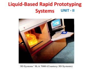
7. These three machines use a different laser from the SLA 250 (solid-state Nd:YVO4
). The SLA 7000 (see Figure) is the top of the series.
8. It can build parts up to four times faster than the SLA 5000 with the capacity of
building thinner layers (minimum layer thickness 0.025 mm) for finer surface
finish. Its faster speed is largely due to its dual spot laser’s ability.
5. 1. This means that a smaller beam spot is used for the border for accuracy,
whereas the bigger beam spot is used for internal crosshatching for
speed.
2. 3D Systems’ new Viper si2 SLA system is their first solid imaging
system to combine standard and high-resolution part building in the
same system.
3. The Viper si2 system lets you choose between standard resolution, for
the best balance of build speed and part resolution, and high resolution
(HR mode) for ultra-detailed small parts and features.
4. All these are made possible by a carefully integrated digital signal
processor (DSP) controlled high speed scanning system with a single,
solid-state laser that delivers a constant 100 mW of available power
throughout its 7500-hour warranty life.
5. The Viper si2 system builds parts with a smooth surface finish, excellent
optical clarity, high accuracy, and thin, straight vertical walls.
6. It is ideal for a myriad of solid imaging applications, from rapid
modeling and prototyping to injection molding and investment casting.
9. 1. The ZephyrTM system which was introduced in 1996 as a product enhancement to
its popular SLA-250 [1] is now used in all the SLA systems with the exception of
SLA 250/30A.
2. The ZephyrTM system eliminates the need for the traditional “deep dip” in which
a part is dunked into the resin vat after each layer and then raised to within one
layer’s depth of the top of the vat.
3. With the deep dip, a wiper blade sweeps across the surface of the vat to remove
excess resin before scanning the next layer.
4. The ZephyrTM system has a vacuum blade that picks up resin from the side of the
vat and applies a thin layer of resin as it sweeps across the part.
5. This speeds up the build process by reducing time required between layers and
greatly reduces problems involved when building parts with trapped volumes.
6. All these machines use one-component, photo-curable liquid resins as the material
for building.
7. There are several grades of resins available and the usage is dependent on the laser
on the machine and the mechanical requirement of the part.
8. Specific details of the correct type of resins to be used are available from the
manufacturer.
9. The other main consumable used on these machines is the cleaning solvent which
is required to clean the part of any residual resin after the building of the part is
10. Advantages and Disadvantages
The main advantages of using SLA are:
(1) Round the clock operation. The SLA can be used
continuously and unattended round the clock.
(2) Good user support. The computerized process serves as a
good user support.
(3) Build volumes. The different SLA machines have build
volumes ranging from small to large to suit the needs of
different users.
(4) Good accuracy. The SLA has good accuracy and can thus
be used for many application areas.
(5) Surface finish. The SLA can obtain one of the best surface
finishes amongst RP technologies.
(6) Wide range of materials. There is a wide range of
materials, from general-purpose materials to specialty
materials for specific applications
11. Disadvantages
The main disadvantages of using SLA are:
(1) Requires support structures. Structures that have overhangs
and undercuts must have supports that are designed and
fabricated together with the main structure.
(2) Requires post-processing. Post-processing includes removal
of supports and other unwanted materials, which is tedious,
time consuming and can damage the model.
(3) Requires post-curing. Post-curing may be needed to cure
the object completely and ensure the integrity of the
structure
12. Process
1. 3D Systems’ stereolithography process creates three-
dimensional plastic objects directly from CAD data.
2. The process begins with the vat filled with the photo-
curable liquid resin and the elevator table set just below
the surface of the liquid resin (see Figure).
3. The operator loads a three-dimensional CAD solid model
file into the system.
4. Supports are designed to stabilize the part during building.
5. The translator converts the CAD data into a STL file.
6. The control unit slices the model and support into a series
of cross sections from 0.025 to 0.5 mm (0.001 to 0.020 in)
thick.
13.
14. 1. The computer-controlled optical scanning system then
directs and focuses the laser beam so that it solidifies
a two dimensional cross-section corresponding to the
slice on the surface of the photo-curable liquid resin
to a depth greater than one layer thickness.
2. The elevator table then drops enough to cover the
solid polymer with another layer of the liquid resin.
3. A leveling wiper or vacuum blade (for ZephyrTM
recoating system) moves across the surfaces to recoat
the next layer of resin on the surface.
4. The laser then draws the next layer.
5. This process continues building the part from bottom
up, until the system completes the part.
6. The part is then raised out of the vat and cleaned of
excess polymer.
15. The main components of the SLA system are a control
computer, a control panel, a laser, an optical system and a
process chamber.
The workstation software used by the SLA system, known as
3D Lightyear exploits the full power of the Windows NT
operating system, and delivers far richer functionality than
the UNIX-based Maestro software.
Maestro includes the following software modules
(1) 3dverifyTM Module. This module can be accessed to confirm the
integrity and/or provide limited repair to stereolithography (STL)
files before part building without having to return to the original
CAD software.
Gaps between triangles, overlapping or redundant triangles and incorrect
normal directions are some examples of the flaws that can be
identified and corrected
16. (2) ViewTM Module. This module can display the STL files and slice file (SLI)
in graphical form. The viewing function is used for visual inspection and
for the orientation of these files so as to achieve optimal building.
(3) MERGE Module. By using MERGE, several SLI files can be merged into a
group which can be used together in future process.
(4) VistaTM Module. This module is a powerful software tool that
automatically generates support structures for the part files. Support
structures are an integral part to successful part building, as they help to
anchor parts to the platform when the part is free floating or there is an
overhang.
(5) Part ManagerTM Module. This software module is the first stage of
preparing a part for building. It utilizes a spreadsheet format into which the
STL file is loaded and set-up with the appropriate build and recoat style
parameters.
(6) SliceTM Module. This is the second stage of preparing a part for building. It
converts the spreadsheet information from the Part ManagerTM module to
a model of three-dimensional cross sections or layers.
(7) ConvergeTM Module. This is the third and last stage of preparing a part for
building. This is the module which creates the final build files used by the
17. Principle
The SLA process is based fundamentally on the following
principles :
(1) Parts are built from a photo-curable liquid resin that cures
when exposed to a laser beam (basically, undergoing the
photopolymerization process) which scans across the
surface of the resin.
(2) The building is done layer by layer, each layer being
scanned by the optical scanning system and controlled by
an elevation mechanism which lowers at the completion
of each layer.
18. • These two principles will be briefly discussed in
this section to lay the foundation to the
understanding of RP processes.
• They are mostly applicable to the liquid-based RP
systems. This first principle deals mostly with
photo-curable liquid resins, which are essentially
photopolymers and the photopolymerization
process.
• The second principle deals mainly with CAD data,
the laser, and the control of the optical scanning
system as well as the elevation mechanism
19. Photopolymers
1. There are many types of liquid photopolymers that
can be solidified by exposure to electro-magnetic
radiation, including wavelengths in the gamma rays, X-
rays, UV and visible range, or electron-beam (EB).
2. The vast majority of photopolymers used in the
commercial RP systems, including 3D Systems’ SLA
machines are curable in the UV range.
3. UV-curable photopolymers are resins which are
formulated from photo initiators and reactive liquid
monomers.
4. There are a large variety of them and some may
contain fillers and other chemical modifiers to meet
specified chemical and mechanical requirements .
5. The process through which photopolymers are cured
is referred to as the photo polymerization process.
20. Photo polymerization
1. Loosely defined, polymerization is the process of linking
small molecules (known as monomers) into chain-like
larger molecules (known as polymers).
2. When the chain-like polymers are linked further to one
another, a cross-linked polymer is said to be formed.
3. Photo polymerization is polymerization initiated by a
photochemical process whereby the starting point is
usually the induction of energy from the radiation source
4. Polymerization of photopolymers is normally an
energetically favorable or exothermic reaction.
5. However, in most cases, the formulation of a
photopolymer can be stabilized to remain un reacted at
ambient temperature.
21. • A catalyst is required for polymerization to take
place at a reasonable rate.
• This catalyst is usually a free radical which may be
generated either thermally or photo chemically.
• The source of a photo chemically generated radical
is a photo initiator, which reacts with an actinic
photon to produce the radicals that catalyze the
polymerization process.
22. 1. The free-radical photopolymerization process is schematically
presented in Figure .
2. Photoinitiator molecules, Pi, which are mixed with the monomers, M,
are exposed to a UV source of actinic photons, with energy of hν.
3. The photoinitiators absorb some of the photons and are in an excited
state.
4. Some of these are converted into reactive initiator molecules, P•, after
undergoing several complex chemical energy transformation steps.
5. These molecules then react with a monomer molecule to form a
polymerization initiating molecule, PM•.
6. This is the chain initiation step.
7. Once activated, additional monomer molecules go on to react in the
chain propagation step, forming longer molecules, PMMM• until a
chain inhibition process terminates the polymerization reaction.
8. The longer the reaction is sustained, the higher will be the molecular
weight of the resulting polymer.
9. Also, if the monomer molecules have three or more reactive chemical
groups, the resulting polymer will be cross-linked, and this will
generate an insoluble continuous network of molecules.
23. 1. During polymerization, it is important that the polymers are
sufficiently cross-linked so that the polymerized molecules do
not redissolve back into the liquid monomers.
2. The photo polymerized molecules must also possess sufficient
strength to remain structurally sound while the cured resin is
subjected to various forces during recoating.
3. While free-radical photo polymerization is well-established
and yields polymers that are acrylate-based, there is another
newer “chemistry” known as cationic photo polymerization.
4. It relies on cationic initiators, usually iodinium or sulfonium
salts, to start polymerization.
5. Commercially available cationic monomers include epoxies,
the most versatile of cationally polymerizable monomers, and
vinylethers.
6. Cationic resins are attractive as prototype materials as they
have better physical and mechanical properties.
7. However the process may require higher exposure time or a
higher power laser
24.
25. Layering Technology, Laser and Laser Scanning
1. Almost all RP systems use layering technology in the creation of
prototype parts.
2. The basic principle is the availability of computer software to slice a
CAD model into layers and reproduce it in an “output” device like a
laser scanning system.
3. The layer thickness is controlled by a precision elevation mechanism.
4. It will correspond directly to the slice thickness of the computer
model and the cured thickness of the resin.
5. The limiting aspect of the RP system tends to be the curing thickness
rather than the resolution of the elevation mechanism.
6. The important component of the building process is the laser and its
optical scanning system.
7. The key to the strength of the SLA is its ability to rapidly direct focused
radiation of appropriate power and wavelength onto the surface of the
liquid photopolymer resin, forming patterns of solidified photopolymer
according to the cross-sectional data generated by the computer
26. 1. In the SLA, a laser beam with a specified power and wavelength is sent
through a beam expanding telescope to fill the optical aperture of a pair
of cross axis, galvanometer driven, beam scanning mirrors.
2. These form the optical scanning system of the SLA.
3. The beam comes to a focus on the surface of a liquid photopolymer,
curing a predetermined depth of the resin after a controlled time of
exposure (inversely proportional to the laser scanning speed).
4. The solidification of the liquid resin depends on the energy per unit area
(or “exposure”) deposited during the motion of the focused spot on the
surface of the photopolymer.
5. There is a threshold exposure that must be exceeded for the
photopolymer to solidify.
6. To maintain accuracy and consistency during part building using the
SLA, the cure depth and the cured line width must be controlled.
7. As such, accurate exposure and focused spot size become essential.
8. Parameters which influence performance and functionality of the parts
are the physical and chemical properties of the resin, the speed and
resolution of the optical scanning system, the power, wavelength and
type of the laser used, the spot size of the laser, the recoating system,
and the post-curing process.
27. Applications
The SLA technology provides manufacturers with cost
justifiable methods for reducing time to market, lowering
product development costs, gaining greater control of their
design process and improving product design.
The range of applications include:
(1) Models for conceptualization, packaging and presentation.
(2) Prototypes for design, analysis, verification and functional
testing.
(3) Parts for prototype tooling and low volume production
tooling.
(4) Patterns for investment casting, sand casting and molding.
(5) Tools for fixture and tooling design, and production
tooling.
28.
29. CUBITAL’S SOLID GROUND CURING (SGC)
Company
1. The Solid Ground Curing (SGC) System is produced by
Cubital Ltd. and its address is Cubital Ltd., 13 Hasadna St.,
P.O.B. 2375, Industrial Zone North Raanana, 43650 Israel.
2. Outside Israel, Cubital America Inc. is located at 1307F
Allen Drive Troy, MI 48083, USA and Cubital GmbH, at
Ringstrasse 132 55543 Bad-Kreuznach, Germany.
3. Cubital Ltd.’s operations began in 1987 as a spin-off from
Scitex Corporation and commercial sales began in 1991
30. Products
Models and Specifications
1. Cubital’s products include the Solider 4600
and Solider 5600.
2. The Solider 4600 is Cubital’s entry level three-
dimensional model making system based on
Solid Ground Curing.
3. The Solider 5600, Cubital’s sophisticated high-
end system, provides a wider range and
options for the varied modeling demands of
Solid Ground Curing. Table summarizes the
specifications of the two machines.
31.
32. • Cubital’s system uses several kinds of resins, including liquid
resin and cured resin as materials to create parts, water soluble
wax as support material and ionographic solid toner for creating
an erasable image of the cross-section on a glass mask.
Advantages and Disadvantages
The Solider system has the following advantages:
(1) Parallel processing. The process is based on instant,
simultaneous curing of a whole cross-sectional layer area
(rather than point-bypoint curing). It has a high speed
throughput that is about eight times faster than its competitors.
Its production costs can be 25% to 50% lower. It is a time and
cost saving process.
(2) Self-supporting. It is user-friendly, fast, and simple to use. It
has a solid modeling environment with unlimited geometry.
The solid wax supports the part in all dimensions and therefore
a support structure is not required.
33. (3) Fault tolerance. It has good fault tolerances. Removable trays
allow job changing during a run and layers are erasable.
(4) Unique part properties. The part that the Solider system
produces is reliable, accurate, sturdy, machinable, and can be
mechanically finished.
(5) CAD to RP software. Cubital’s RP software, Data Front End
(DFE), processes solid model CAD files before they are
transferred to the Cubital’s machines. The DFE is an interactive
and user friendly software.
(6) Minimum shrinkage effect. This is due to the full curing of
every layer.
(7) High structural strength and stability. This is due to the curing
process that minimizes the development of internal stresses in
the structure. As a result, they are much less brittle.
(8) No hazardous odors are generated. The resin stays in a liquid
state for a very short time, and the uncured liquid is wiped off
immediately. Thus safety is considerably higher
34. The Solider system has the following disadvantages:
(1) Requires large physical space. The size of the system is
much larger than other systems with a similar build
volume size.
(2) Wax gets stuck in corners and crevices. It is difficult to
remove wax from parts with intricate geometry. Thus,
some wax may be left behind.
(3) Waste material produced. The milling process creates
shavings, which have to be cleaned from the machine.
(4) Noisy. The Solider system generates a high level of noise
as compared to other systems.
35. Process
The Cubital’s Solid Ground Curing process includes three main steps: data preparation,
mask generation and model making
36. Data Preparation
1. In this first step, the CAD model of the job to be
prototyped is prepared and the cross-sections are
generated digitally and transferred to the mask
generator.
2. The software used, Cubital’s Solider DFE (Data Front
End) software, is a motif-based special-purpose CAD
application package that processes solid model CAD
files prior to sending them to Cubital Solider system.
3. DFE can search and correct flaws in the CAD files and
render files on-screen for visualization purposes.
4. Solider DFE accepts CAD files in the STL format and
other widely used formats exported by most
commercial CAD systems.
37. Mask Generation
• After data are received, the mask plate is charged
through an “image wise” ionographic process (see
item 1, Figure).
• The charged image is then developed with
electrostatic toner
38. Model Making
1. In this step, a thin layer of photopolymer resin is spread on the
work surface (see item 2, Figure).
2. The photo mask from the mask generator is placed in close
proximity above the work piece, and aligned under a
collimated UV lamp (item 3).
3. The UV light is turned on for a few seconds (item 4).
4. The part of the resin layer which is exposed to the UV light
through the photo mask is hardened.
5. Note that the layers laid down for exposure to the lamp are
actually thicker than the desired thickness. This is to allow for
the final milling process.
6. The un solidified resin is then collected from the work
piece (item 5). This is done by vacuum suction.
39. 1. Following that, melted wax is spread into the
cavities created after collecting the liquid resin
(item 6).
2. Consequently, the wax in the cavities is cooled to
produce a wholly solid layer.
3. Finally, the layer is milled to its exact thickness,
producing a flat solid surface ready to receive the
next layer (item 7).
4. In the SGC 5600, an additional step (item 8) is
provided for final curing of the layer whereby the
work piece travels under a powerful longitudinal
UV lamp.
5. The cycle repeats itself until the final layer is
completed.
40. • The main components of the Solider system are
(see Figure):
• (1) Data Front End (DFE) workstation.
• (2) Model Production Machine (MPM). It includes:
(i) Process engine, (ii) Operator’s console, (iii)
Vacuum generator.
• (3) Automatic Dewaxing Machine (optional).
41.
42. Principle
• Cubital’s RP technology creates highly physical
models directly from computerized three-
dimensional data files.
• Parts of any geometric complexity can be produced
without tools, dies or molds by Cubital’s RP
technology.
• The process is based on the following principles:
43. • (1) Parts are built, layer by layer, from a liquid photopolymer
resin that solidifies when exposed to UV light.
• The photo polymerization process is similar to that described
in Section 3.1.4, except that the irradiation source is a high
power collimated UV lamp and the image of the layer is
generated by masked illumination instead of optical scanning
of a laser beam.
• The mask is created from the CAD data input and “printed”
on a transparent substrate (the mask plate) by an nonimpact
ionographic printing process, a process similar to the
Xerography process used in photocopiers and laser printers .
• The image is formed by depositing black powder, a toner
which adheres to the substrate electro statically.
• This is used to mask the uniform illumination of the UV lamp.
After exposure, the electrostatic toner is removed from the
substrate for reuse and the pattern for the next layer is
similarly “printed” on the substrate.
44. • (2) Multiple parts may be processed and built in parallel by
grouping them into batches (runs) using Cubital’s
proprietary software.
• (3) Each layer of a multiple layer run contains cross-
sectional slices of one or many parts.
• Therefore, all slices in one layer are created simultaneously.
Layers are created thicker than desired.
• This is to allow the layer to be milled precisely to its exact
thickness, thus giving overall control of the vertical
accuracy.
• This step also produces a roughened surface of cured
photopolymer, assisting adhesion of the next layer to it.
• The next layer is then built immediately on the top of the
created layer.
• (4) The process is self-supporting and does not require the
addition of external support structures to emerging parts
since continuous structural support for the parts is provided
by the use of wax, acting as a solid support material.
45. Applications
1. The applications of Cubital’s system can be divided into
four areas:
2. General applications. Conceptual design
presentation, design proofing, engineering testing,
integration and fitting, functional analysis, exhibitions
and pre-production sales, market research, and inter-
professional communication.
3. Tooling and casting applications. Investment
casting, sand casting, and rapid, tool-free
manufacturing of plastic parts.
4. Mold and tooling. Silicon rubber tooling, epoxy tooling,
spray metal tooling, acrylic tooling, and plaster mold
casting.
5. Medical imaging. Diagnostic, surgical, operation and
re construction planning and custom prosthesis design.
46. Examples or case studies
• Cubital Prototyping Machine Builds Jeep in 24 Hours.
47. 1. Toledo Model and Die Inc. (TMD) of Toledo, Ohio, has
used Cubital’s Solider 5600 rapid prototyping system to
produce three design iterations of a toy jeep (Figure ) in
three days .
2. The plastic push toy is about 30 cm (12 in) long, 23 cm (9
in) wide and 23 cm (9 in) high.
3. Using the Cubital Solider 5600, TMD was able to produce
each design iteration in 13 hours of machine time.
4. By using the Cubital front-end software, the parts were
“nested” within a working volume only 10 cm (4 in) deep,
within the Solider’s working area 50 cm × 35 cm (20 in by
14 in).
5. Initial file checking and post-production wax removal
accounted for the rest of the 24 hours.
49. 1. Schneider Prototyping GmbH created a metal
prototype (see Figure) for investment cast directly
from CAD files in two weeks with SoliCast.
2. Starting with a CAD file, Schneider can deliver a
metal prototype in two weeks, whereas similar
processes with other rapid prototyping methods
take four to six weeks and conventional methods
based on CNC prototyping can take 10 to 16
weeks.
3. In general, Schneider’s prototypes can be as much
as 50% cheaper than those produced by other
rapid prototyping methods.
50. Cubital Saves the Day — In Fact, About Six
Weeks — For Pump Developers
51. 1. Engineers and technicians in the production
engineering department of Sintef, a research and
development firm in Trondheim, Norway, made an
accurate, full scale plastic model of the impeller
(Figure ), which measures about 220 mm in
diameter and 50 mm high, using their Solider 5600
2. This model was used to create an investment
casting pattern that was used to cast a prototype
impeller in metal.
3. From the time the engineers in Sintef got the CAD
files till they had the investment casting pattern
was three weeks — about a third the time it would
have taken using CNC tools