SlideShare a Scribd company logo
1 of 24
Download to read offline
1
CHAPTER-1
INTRODUCTION
Microcontroller based traffic control system is an application specific project, which is used to control the
traffic. An embedded system is developed which consists of a microcontroller, IR transmitter and receiver, LED’s.
This project is implemented by placing IR transmitters, receivers and LED’s at the 4 way junction, the four paths
are represented as R1,R2,R3,R4. Transmitters and receivers are placed at either sides of the four paths, and 3
LED’s at each corner of the junction. When there is a traffic along the paths, value of R would be 00 which are the
values of IR sensors and if there is no traffic the value is 11.
For instance, let the traffic at the path R1 be initially 11 i.e. there is no traffic , when the traffic reaches the
first sensor, the value of R would be 01,if it reaches second sensor ,the value of R is 00,it is recognized that traffic
is heavy and the led glows which indicates that vehicles can move forward, traffic is cleared, and the sensor values
automatically changed to 11.the control goes to the next path when the values of sensors contains more no of
zeroes.
Fig.1: Density dependent traffic control
This entire embedded system is placed at that junction Microcontroller is interfaced with LED’s and IR
sensors The total no of IR sensors required are 8 and LED’s 12. Therefore these are connected to any two ports of
microcontroller.
2
1.1 BLOCK DIAGRAM:
Fig.2: Block Diagram
1.2 BLOCK DIAGRAM DESCRIPTION:
The block diagram consists of microcontroller interfaced to regulated power supply, led and IR receiver
and IR transmitter which consists of an IR sensor .The IR sensors and LED’s are connected to any of the port pins
of microcontroller, regulated power supply is connected to the Vcc pin of microcontroller which uses an voltage
regulator to get 5 v of power supply. The transmit pin of IR receiver is connected to the receive pin of
microcontroller. This embedded system is placed at the 4 way junction which controls the traffic electronically.
The system uses a compact circuitry of Atmega8 Microcontroller. Programs will be developed in EMBEDDED C
language. This project is implemented by placing IR transmitters, receivers. Basically an IR sensor is used for
detecting an obstacle, there are some areas where valuable things are placed, an IR transmitter and receiver is
placed there, an infrared path is established and if any person comes into that path the buzzer gets on which gives
out a long beep Similarly a fire sensor is used to detect fire. The purpose of the transmitter is to transform the
REGULATED
POWER
SUPPLY
IR
RECIEVER
LED
ATMEGA8
MICRO
CONTROLLER
IR
TRANSMITTER
3
information we want to send into a signal that can be propagated by the channel. The receiver in this module
requires the incoming data to be modulated at a particular frequency and would ignore any other IR signals.
1.3 PURPOSE OF PROJECT:
The project is aimed at designing a density based dynamic traffic signal system where the timing of signal
will change automatically on sensing the traffic density at any junction . The traffic lights that are in widespread
use today do not do much intricate reasoning when deciding when to change the lights for the various road users
waiting in different lanes. How long the signal stays green in one lane and red in another is most often determined
by simple timing that is calculated when the crossing is designed. Even though today’s methods are robust and
work well when the traffic load is distributed evenly across the lanes in the intersection, the systems are very
inefficient because they are unable to handle various simple situations that arise throughout the day. Unnecessary
waiting time in the signal can be avoided by determining in which side the green signal should be large during the
traffic.
4
CHAPTER-2
OPERATION OF DENSITY BASED TRAFFIC LIGHT CONTROLLER
2.1 PRINCIPLE:
A prototype of traffic light control system is made by using Infra-Red sensors along with major
components Microcontroller and LEDs which are used for controlling traffic signals based on the density of the
traffic. The junction taken into consideration is a four-side junction with the traffic flow on each side is only in one
direction. This traffic light control system consists of the following three main components:
 Display Unit: It consists of 3 LEDs: Green, Red and Orange on each side of the junction– a total of 12
LEDs of three colors are placed at the junction.
 Detector Unit: It consists of a combined arrangement of photo diode and IR LED at every junction for
detecting the presence of vehicles based on the change in resistance.
 Controller Unit: This control unit contains a microcontroller which receives the output data from the IR
Sensors and controls the glowing of LEDs based on the programming.
This traffic light control system works on the concept of fixed time allocation at each side of the junction
which cannot be changed as per varying traffic density. Timings allotted at every junction are fixed .Sometimes
higher traffic density at one side of the junction demands longer time duration for green signal compared to the
standard allotted time.
This proposed system makes use of an Atmega8 microcontroller which is properly interfaced with the IR
sensors to change the junction timing automatically to accommodate the movement of vehicles for avoiding
unnecessary waste of time at each junction.
The sensors used in this project IR and photo diodes are in line of sight configuration across the loads to
detect the density at the traffic signal. The density of these vehicles is measured in three zones i.e., low, medium
and high, respectively – based on certain time duration allotted at respective zones, accordingly.
2.2 WORKING:
In this system, we will use IR sensors to measure the traffic density. We have to arrange one IR sensor for
each road; these sensors always sense the traffic on that particular road. All these sensors are interfaced to the
microcontroller. Based on these sensors, controller detects the traffic and controls the traffic system. The main
heart of this traffic system is microcontroller.IR sensors are connected to the PORT of the microcontroller and
5
traffic lights are connected to PORT of microcontroller. If there is traffic on road then that particular sensor output
becomes logic 0 otherwise logic1. By receiving these IR sensor outputs, we have to write the program to control
the traffic system.
6
CHAPTER-3
CIRCUIT DISCRIPTION
3.1 CIRCUIT DIAGRAM:
Fig.3: Circuit Design in Proteus
The major part of this electronic system is microcontroller. All the operation are controlled by it.
 Connect 12V battery or adaptor to the development board.
 Switch on the supply.
 Burn the program to the ATmega8 microcontroller by keeping the programming switch sw2 in program
mode.
 Connect four IR sensors to PORT C.
 Connect LEDs to PORT B and PORT D.
 Arrange all this LED’s same as like traffic lights.
7
 Arrange one IR sensor for each road.
 Now you can see the normal traffic system based on time basis.
 Now if you place any obstacle in front of any IR sensor, then the system allows the traffic of that particular
path by glowing GREEN light.
 Finally, turn off the board power supply
3.2 COMPONENT USED:
 MICROCONTROLLER (ATMEGA8)
 IR SENSOR
 RESISTANCE
 LED
 CAPACITOR
 IC 555
 CONNECTING WIRES
3.3 COMPONENT DISCRIPTION:
3.3.1 ATMEGA 8:
The Atmel®AVR® ATmega8 is a low-power CMOS 8-bit microcontroller based on the AVR RISC
architecture. By executing powerful instructions in a single clock cycle, the ATmega8 achieves throughputs
approaching 1MIPS per MHz, allowing the system designer to optimize power consumption versus processing
speed.
PIN DISCRIPTION:
 VCC: Digital supply voltage.
 GND: Ground.
 Port B (PB7..PB0) XTAL1/XTAL2/TOSC1/TOSC2: Port B is an 8-bit bi-directional I/O port with
internal pull-up resistors (selected for each bit). ThePort B output buffers have symmetrical drive
characteristics with both high sink and source capability. As inputs, Port B pins that are externally pulled
low will source current if the pull-up resistors are activated. The Port B pins are tri-stated when a reset
condition becomes active , even if the clock is not running. Depending on the clock selection fuse settings,
PB6 can be used as input to the inverting Oscillator amplifier and input to the internal clock operating
8
circuit. Depending on the clock selection fuse settings, PB7 can be used as output from the inverting
Oscillator amplifier. If the Internal Calibrated RC Oscillator is used as chip clock source, PB7..6 is used as
TOSC2..1 input for the Asynchronous Timer/Counter2 if the AS2 bit in ASSR is set.
Fig.4- Pin Diagram of ATMEGA8
 Port C (PC5..PC0) : Port C is an 7-bit bi-directional I/O port with internal pull-up resistors (selected for
each bit). The Port C output buffers have symmetrical drive characteristics with both high sink and source
capability. As inputs, Port C pins that are externally pulled low will source current if the pull-up resistors
are activated. The Port C pins are tri-stated when a reset condition becomes active, even if the clock is not
running. PC6/RESET If the RSTDISBL Fuse is programmed, PC6 is used as an I/O pin. Note that the
electrical characteristics of PC6 differ from those of the other pins of Port C. If the RSTDISBL Fuse is
unprogrammed, PC6 is used as a Reset input. A low level on this pin for longer than the minimum pulse
length will generate a Reset, even if the clock is not running. The minimum pulse length is given in Table
15 on page 38. Shorter pulses are not guaranteed to generate a Reset.
 Port D (PD7..PD0): Port D is an 8-bit bi-directional I/O port with internal pull-up resistors (selected for
each bit). The Port D output buffers have symmetrical drive characteristics with both high sink and source
capability. As inputs, Port D pins that are externally pulled low will source current if the pull-up resistors
9
are activated. The Port D pins are tri-stated when a reset condition becomes active, even if the clock is not
running.
 RESET: Reset input. A low level on this pin for longer than the minimum pulse length will generate a
reset, even if the clock is not running. Shorter pulses are not guaranteed to generate a reset.
 Vcc: Vcc is the supply voltage pin for the A/D Converter, Port C (3..0), and ADC (7..6). It should be
externally connected to VCC, even if the ADC is not used. If the ADC is used, it should be connected to
VCC through a low-pass filter. Note that Port C (5..4) use digital supply voltage, VCC.
 AREF: AREF is the analog reference pin for the A/D Converter.
 ADC7..6 (TQFP and QFN/MLF Package Only): In the TQFP and QFN/MLF package, ADC7..6 serve as
analog inputs to the A/D converter. These pins are powered from the analog supply and serve as 10-bit
ADC channels.
Features
 High-performance, Low-power Atmel®AVR® 8-bit Microcontroller
 Advanced RISC Architecture
– 130 Powerful Instructions – Most Single-clock Cycle Execution
– 32 × 8 General Purpose Working Registers
– Fully Static Operation
– Up to 16MIPS Throughput at 16MHz
– On-chip 2-cycle Multiplier
 High Endurance Non-volatile Memory segments
– 8Kbytes of In-System Self-programmable Flash program memory
– 512Bytes EEPROM
– 1Kbyte Internal SRAM
– Write/Erase Cycles: 10,000 Flash/100,000 EEPROM
– Data retention: 20 years at 85°C/100 years at 25°C(1)
– Optional Boot Code Section with Independent Lock Bits. In-System Programming by
– On-chip Boot Program. True Read-While-Write Operation
– Programming Lock for Software Security
 Peripheral Features
– Two 8-bit Timer/Counters with Separate Pre scaler, one Compare Mode
10
– One 16-bit Timer/Counter with Separate Pre scaler, Compare Mode, and Capture. Mode
– Real Time Counter with Separate Oscillator
– Three PWM Channels
– 8-channel ADC in TQFP and QFN/MLF package
 Eight Channels 10-bit Accuracy
– 6-channel ADC in PDIP package. Six Channels 10-bit Accuracy
– Byte-oriented Two-wire Serial Interface
– Programmable Serial USART
– Master/Slave SPI Serial Interface
– Programmable Watchdog Timer with Separate On-chip Oscillator
– On-chip Analog Comparator
 Special Microcontroller Features
– Power-on Reset and Programmable Brown-out Detection
– Internal Calibrated RC Oscillator
– External and Internal Interrupt Sources
– Five Sleep Modes: Idle, ADC Noise Reduction, Power-save, Power-down, and Standby
 I/O and Packages
– 23 Programmable I/O Lines
– 28-lead PDIP, 32-lead TQFP, and 32-pad QFN/MLF
 Operating Voltages
– 2.7V - 5.5V (ATmega8L)
– 4.5V - 5.5V (ATmega8)
 Speed Grades
– 0 - 8MHz (ATmega8L)
– 0 - 16MHz (ATmega8)
 Power Consumption at 4Mhz, 3V, 25 degreeC
– Active: 3.6mA
– Idle Mode: 1.0mA
– Power-down Mode: 0.5µA
11
3.3.2 IR SENSOR
IR (INFRARED) sensor is based on LM 358 IC which is an Operational amplifier acting as
comparator. The comparator compares the analog voltages of potentiometer and the voltage generated by
the photodiode. The two voltages are applied on the two terminals of the IC and correspondingly it generates a
digital output on the output pin that is indicated by a Red LED. The IR sensor is compatible with various
microcontroller boards like 8051, Arduino , pic etc. This shield is based on the working of a circuit comprising
op-amp, an IR led and photodiode the output generate by the sensor is due the comparator action of the op amp
(LM358). The Compares the two voltages that is generated by the photodiode and the potentiometer. When
the value of voltage Vd generated by photodiode is greater than the voltage set on the potentiometer, the
output is HIGH and vice versa.
Fig:5 IR sensor
Technical Specifications:
 2-12cm range
 Potentiometer for maximum range setting can be used to differentiate between black and white (Can be
used for line sensing) .
 Onboard LED indication for detection
 Works on 5V input.
 TTL compatible output .
 LM358 IC (Integrated Circuit) that acts as a comparator/ ADC (Analog to Digital Converter) IC which
makes it digital sensor.
12
IR Transmitter and Receiver
The purpose of the transmitter is to transform the information we want to send into a signal that can be
propagated by the channel. In the case of our wired copper channel, this means we want the information to be
transformed into a modulated voltage level, something like the pulse train. For a wireless channel, however, the
transmitter needs to encode the information onto an EM wave that can be easily propagated.
IR Transmitter:
The IR transmitter part consists of an Infra red light emitting diode that can capable of sending modulated
data within infra red band. To match the receiver frequency the data is modulated at 38.7 KHZ by configuring 555
timer at astable mode of operation, which generates frequency using the components R2 and C2 as shown in above
fig. This frequency can be varied over a long range just by varying the preset R1 and C1.
Fig.6: IR Transmitter circuit
IR Receiver:
The IR receiver consists of TSOP 1738 module which is a simple yet effective IR proximity sensor built
around the TSOP 1738 module. The TSOP module is commonly found at the receiving end of an IR remote
control system; e.g., in TVs, CD players etc. These modules require the incoming data to be modulated at a
particular frequency and would ignore any other IR signals. It is also immune to ambient IR light, so one can
easily use these sensors outdoors or under heavily lit conditions. Such modules are available for different carrier
frequencies from 32 kHz to 42kHz.
In this particular proximity sensor, we will be generating a constant stream of square wave signal using
IC555 centered at 38 kHz and would use it to drive an IR led. So whenever this signal bounces off the obstacles,
the receiver would detect it and change its output. Since the TSOP 1738 module works in the active-low
configuration, its output would normally remain high and would go low when it detects the signal (the obstacle).
Basically an IR sensor is used for detecting an obstacle, there are some areas where valuable things are
placed, an IR transmitter and receiver is placed there, an infrared path is established and if any person comes into
that path the buzzer gets on which gives out a long beep Similarly a fire sensor is used to detect fire
13
The sensed data is given to the microcontroller, processing is done according to the logic in the
microcontroller and then writes onto GSM which will further send sms to the mobile at the user
A buzzer is interfaced to microcontroller to give out a beep sound whenever an obstacle and fire is
detected.
Fig.7: IR Receiver Circuit
3.3.3 RESISTOR:
The electrical resistance of an electrical conductor is the opposition to the passage of an electric current
through that conductor. The inverse quantity is electrical conductance, the ease with which an electric current
passes. Electrical resistance shares some conceptual parallels with the notion of mechanical friction. The SI unit
of electrical resistance is the ohm (Ω), while electrical conductance is measured in siemens (S). An object of
uniform cross section has a resistance proportional to its resistivity and length and inversely proportional to its
cross-sectional area. All materials show some resistance, except for superconductors, which have a resistance of
zero.
Fig.8: Resistor
14
3.3.4 LED:
A light-emitting diode (LED) is a two-lead semiconductor HYPERLINK light source. It is a pnjunction
HYPERLIN diode, which emits light when activated. When a suitable voltage is applied to the leads, electrons
are able to recombine with electron holes within the device, releasing energy in the form of photons. This effect is
called electroluminescence, and the color of the light (corresponding to the energy of the photon) is determined by
the energy band gap of the semiconductor.
Fig.9: LED
3.3.5 CAPACITOR:
Capacitors are electronic devices which essentially store energy as an electrostatic field, and are composed
of an insulating material placed between two conductive plates. In PCBs, they can block the flow of direct current
while enabling the flow of indirect current. When DC voltage is applied to a capacitor, the electric charge is stored
by each conductive plate. Current flows while the capacitor is storing energy—when the capacitor is full, current
stops flowing. The type of material used as the insulating material (a dielectric material) determines capacitor type.
Common insulator materials include ceramic, polycarbonate and silver mica. In PCBs, the board itself often
creates a capacitor, with alternating layers of metal conductive areas, ground conductor and powder conductor,
creating a stable capacitor. Within PCBs, decoupling capacitors can be found, which serve to reduce the noise and
effects of other elements on the rest of the circuit board by routing such noise through the capacitor which can then
store the excess energy.
To test a capacitor in a PCB, one end of the capacitor should be removed from the circuit. The power
supply of DC voltage should match the range of the capacitor so as not to overload the device. When voltage is
applied several outcomes are possible: if the capacitor has shorted the meter will simply reflect the output voltage
of the power supply; if the capacitor is leaking the meter reading will jump high and then drop low again (but not
15
all the way to zero); if the meter registers no jump at all, the capacitor is either open or capacitance is too low to
register a result.
Fig.10.Capacitor
3.3.6 IC555
The 555 timer IC is an integrated circuit (chip) used in a variety of timer, pulse generation, and oscillator
applications. The 555 can be used to provide time delays, as an oscillator, and as a flip-flop element. Derivatives
provide two or four timing circuits in one package.
PIN DISCRIPTION:
GND Ground reference voltage, low level (0 V)
TRIG
The OUT pin goes high and a timing interval starts when this input falls below 1/2 of CTRL voltage
(which is typically 1/3 VCC, CTRL being 2/3 VCC by default if CTRL is left open). More simply we can
say that OUT will be high as long as the trigger is kept at low voltage. Output of the timer totally
depends upon the amplitude of the external trigger voltage applied to this pin.
OUT This output is driven to approximately 1.7 V below +VCC, or to GND.
RESET
A timing interval may be reset by driving this input to GND, but the timing does not begin again until
RESET rises above approximately 0.7 volts. Overrides TRIG which overrides THR.
CTRL Provides "control" access to the internal voltage divider (by default, 2/3 VCC).
16
THR
The timing (OUT high) interval ends when the voltage at THR ("threshold") is greater than that at
CTRL (2/3 VCC if CTRL is open).
DIS Open collector output which may discharge a capacitor between intervals. In phase with output.
VCC Positive supply voltage, which is usually between 3 and 15 V depending on the variation.
Fig.11 IC 555
3.3.7 LDR
A photoresistor or light-dependent resistor (LDR) or photocell is a light-controlled variable resistor. The
resistance of a photoresistor decreases with increasing incident light intensity; in other words, it exhibits
photoconductivity. A photoresistor can be applied in light-sensitive detector circuits, and light- and dark-activated
switching circuits. A photoresistor is made of a high resistance semiconductor. In the dark, a photoresistor can have a
resistance as high as a few mega ohms (MΩ), while in the light, a photoresistor can have a resistance as low as a few hundred
ohms. If incident light on a photoresistor exceeds a certain frequency, photons absorbed by the semiconductor give bound
electrons enough energy to jump into the conduction band. The resulting free electrons (and its hole partners) conduct
electricity, thereby lowering resistance.
Fig.12 LDR
17
CHAPTER-4
SOFTWARE USASGE
4.1 INSTALLING TOOLS FOR C PROGRAMMING:
To work with the Atmel AVR microcontroller using the C programming language, two tools are required:
AVR Studio and AVR.
1. AVR Studio is an integrated development environment that includes an editor, the assembler, HEX file
downloader and a microcontroller emulator.
2. ICC AVR is for a ICC-based compiler for AVR. It appears in AVR Studio as a plugin. ICC AVR also includes
a program called Programmer’s Notepad that can be used to edit and compile C programs, independently of AVR
Studio. Installing these tools is easy, just download and run the setup files, and accept the default installation
options. Remember to install AVR Studio first before ICC-AVR.
3. It supports inline assembly and can interface with assembly modules.
4. It supports all AT90S and Atmega devices and AT94K FPSLIC.
5. Modern IDE with code folding, workspace and project management, one click access to function definitions,
etc
.
Fig.13: AVR studio
18
4.2 USING AVR STUDIO FOR C PROGRAMMING:
After creating a simple C program for the Atmel AVR you will be guided through four major stages:
1. Creating an AVR Studio project.
2. Compiling C code to HEX file.
3. Debugging C program using the simulator.
4. Downloading HEX file to the proteus software and simulating it.
4.4.1 CREATING AN ICC AVR PROJECT:
Perform the following steps to create a simple AVR project.
1. Start the ICC AVR program by selecting atmega 8 from application builder.
2. Select Project | New Project. In the dialog box that appears and specify the project name and project location.
If options ‘Create new file’, an empty C file and will be created for you. In this case, we create a file called ‘led’.
3. In the ‘Select debug platform and device’ dialog that appears choose ‘AVR Simulator’ as the debug platform
and ‘ATMEGA32’ as the device. Click button Finish.
4. A project file will be created and ICC AVR displays an empty file led.. Enter the C code.
Fig 14: The ICC AVR with a project file open.
19
4.4.2 COMPILING C CODE TO HEX FILE:
1. Click menu Build | Rebuild All to compile the C code.
2. If there is no error message, a file called led.hex will be produced .This file contains the machine code that is
ready to be downloaded to the ATMEGA32 microcontroller. The file is stored in sub-folder ‘default’ of your
project.
3. If there are error messages, check your C code. Most often, they are caused by some typos or syntax errors.
4. And after checking this program, burn on burner kit so that hardware can work
Fig 15: Compiling code
5. While debugging the C program, you can change the contents of a register. For example, to change Port A Input
Pins register (PINA), click on the value column of PINA and enter a new value This change takes effect
immediately. Subsequently, the contents of PORTB will be 0x04 after running the two C instruction.
6. To monitor a C variable, select the variable name in the code window and click menu.
7. Debug | Quick Watch. The variable will be added to a watch window.
4.4.3 SIMULATION PROCESS :
1. Proteus8.1 is best simulation software for various designs with microcontroller.
20
2. It is a handy tool to test programs and embedded designs for electronics hobbyist.
3. Basically PROTEUS is also simulating software but it helps you attach many components with the 8051. Like
resistors, capacitors, LEDs, LCDs, keypads, ICs etc. and these are just few that I have named in general. It has a
complete library and you will find everything that you will ever need. You can design your complete circuit and
then simulate it to view the final output. This means that after perfecting your project on the programming side in
KEIL, you'll need to simulate it on PROTEUS to determine the output of the hardware components and change it
if need be. This will completely ensure your project's success
4. Open the Proteus and then create a new project by clicking on new project button.
5. Now give a Name to our project and do not change anything, just follow the default options and click Next until
you see Finish button.
6. Draw the circuit diagram by clicking on Schematic Capture button and then add the components by Click P
button followed by Component button under Devices for picking components.
7. Choose your component by simply typing the name at Keyword box. After selecting item click OK and the
selected components will listed under Devices.
8. Now draw the circuit diagram i.e. make the connection.
9. Simulate the circuit by clicking on run button.
Fig.16: Output when simulation start on proteus
21
4.5 PROGRAMMING:
#define F_CPU 8000000UL
#include <avr/io.h>
#include <util/delay.h>
#define R1 PB0
#define Y1 PB1
#define G1 PB2
#define R2 PB3
#define Y2 PB4
#define G2 PB5
#define R3 PD5
#define Y3 PD4
#define G3 PD3
#define R4 PD2
#define Y4 PD1
#define G4 PD0
int main(void)
{
DDRB = 0xff;
DDRD = 0xff;
DDRC = 0x00;
PORTB = 0x00;
PORTD = 0x00;
while(1)
{
22
if((PINC&0x01) == 0x01)
{
PORTB |= (1<<G1);
PORTB |= (1<<Y2);
PORTD |= (1<<R3);
PORTD |= (1<<R4);
}
else if((PINC&0x02) == 0x02)
{
PORTB |= (1<<R1);
PORTB |= (1<<G2);
PORTD |= (1<<Y3);
PORTD |= (1<<R4);
}
else if((PINC&0x04) == 0x04)
{
PORTB |= (1<<R1);
PORTB |= (1<<R2);
PORTD |= (1<<G3);
PORTD |= (1<<Y4);
}
else if((PINC&0x08) == 0x08)
{
PORTB |= (1<<Y1);
PORTB |= (1<<R2);
23
PORTD |= (1<<R3);
PORTD |= (1<<G4);
}
else
{
PORTB = 0x00;
PORTD = 0x00;
PORTB |= (1<<G1);
PORTB |= (1<<Y2);
PORTD |= (1<<R3);
PORTD |= (1<<R4);
_delay_ms(7000);
PORTB = 0x00;
PORTD = 0x00;
PORTB |= (1<<R1);
PORTB |= (1<<G2);
PORTD |= (1<<Y3);
PORTD |= (1<<R4);
_delay_ms(7000);
PORTB = 0x00;
PORTD = 0x00;
PORTB |= (1<<R1);
PORTB |= (1<<R2);
PORTD |= (1<<G3);
PORTD |= (1<<Y4);
24
_delay_ms(7000);
PORTB = 0x00;
PORTD = 0x00;
PORTB |= (1<<Y1);
PORTB |= (1<<R2);
PORTD |= (1<<R3);
PORTD |= (1<<G4);
_delay_ms(7000);
PORTB = 0x00;
PORTD = 0x00;
}
}
}

More Related Content

What's hot

Automatic speed controller in real time vehicles.
Automatic speed controller in real time vehicles.Automatic speed controller in real time vehicles.
Automatic speed controller in real time vehicles.Jinto George
 
Traffic light controller
Traffic light controllerTraffic light controller
Traffic light controllerRkrishna Mishra
 
Vlsi lab viva question with answers
Vlsi lab viva question with answersVlsi lab viva question with answers
Vlsi lab viva question with answersAyesha Ambreen
 
Alcohol sensing alert with engine locking project
Alcohol sensing alert with engine locking projectAlcohol sensing alert with engine locking project
Alcohol sensing alert with engine locking projecthemanth prudhvi jidugu
 
design of FPGA based traffic light controller system
design of FPGA based traffic light controller systemdesign of FPGA based traffic light controller system
design of FPGA based traffic light controller systemVinny Chweety
 
Synopsis for alcohol detection with vehicle controlling (1)
Synopsis for alcohol detection with vehicle controlling (1)Synopsis for alcohol detection with vehicle controlling (1)
Synopsis for alcohol detection with vehicle controlling (1)Pankaj Singh
 
smart traffic light control system
smart traffic light control systemsmart traffic light control system
smart traffic light control systemarunkumar6836
 
Traffic light controller
Traffic light controllerTraffic light controller
Traffic light controllerSrikanth Kaleru
 
Applications of 8051 microcontrollers
Applications of 8051 microcontrollersApplications of 8051 microcontrollers
Applications of 8051 microcontrollersDr.YNM
 
soldier tracking and health monitoring system
soldier tracking and health monitoring systemsoldier tracking and health monitoring system
soldier tracking and health monitoring systemJoshpin Bala.B
 
density based traffic monitoring system
density based traffic monitoring system density based traffic monitoring system
density based traffic monitoring system siddhartha shukla
 
Intelligent alcohol detection system for car
Intelligent alcohol detection system for carIntelligent alcohol detection system for car
Intelligent alcohol detection system for carLogic Mind Technologies
 
Pic microcontroller architecture
Pic microcontroller architecturePic microcontroller architecture
Pic microcontroller architectureDominicHendry
 
Automatic engine locking system for drunken driver
Automatic engine locking system for drunken driverAutomatic engine locking system for drunken driver
Automatic engine locking system for drunken driverdodosgusenga
 
Vehicle accident detection and messaging system using GSM and arduino
Vehicle accident detection and messaging system using GSM and arduinoVehicle accident detection and messaging system using GSM and arduino
Vehicle accident detection and messaging system using GSM and arduinoRamesh Reddy
 
Ppt on brake failure indicator.
Ppt on brake failure indicator.Ppt on brake failure indicator.
Ppt on brake failure indicator.mmnbaig
 
Accident Detection and Ambulance Triggered Traffic Management Systems
Accident Detection and Ambulance Triggered Traffic Management SystemsAccident Detection and Ambulance Triggered Traffic Management Systems
Accident Detection and Ambulance Triggered Traffic Management SystemsSachin Kumar Asokan
 
Density based trafiic control
Density based trafiic controlDensity based trafiic control
Density based trafiic controlnskprasad
 
Report of Advance car security system major project
Report of Advance car security system major projectReport of Advance car security system major project
Report of Advance car security system major projectAmi Goswami
 

What's hot (20)

Automatic speed controller in real time vehicles.
Automatic speed controller in real time vehicles.Automatic speed controller in real time vehicles.
Automatic speed controller in real time vehicles.
 
Traffic light controller
Traffic light controllerTraffic light controller
Traffic light controller
 
Vlsi lab viva question with answers
Vlsi lab viva question with answersVlsi lab viva question with answers
Vlsi lab viva question with answers
 
Alcohol detector
Alcohol detectorAlcohol detector
Alcohol detector
 
Alcohol sensing alert with engine locking project
Alcohol sensing alert with engine locking projectAlcohol sensing alert with engine locking project
Alcohol sensing alert with engine locking project
 
design of FPGA based traffic light controller system
design of FPGA based traffic light controller systemdesign of FPGA based traffic light controller system
design of FPGA based traffic light controller system
 
Synopsis for alcohol detection with vehicle controlling (1)
Synopsis for alcohol detection with vehicle controlling (1)Synopsis for alcohol detection with vehicle controlling (1)
Synopsis for alcohol detection with vehicle controlling (1)
 
smart traffic light control system
smart traffic light control systemsmart traffic light control system
smart traffic light control system
 
Traffic light controller
Traffic light controllerTraffic light controller
Traffic light controller
 
Applications of 8051 microcontrollers
Applications of 8051 microcontrollersApplications of 8051 microcontrollers
Applications of 8051 microcontrollers
 
soldier tracking and health monitoring system
soldier tracking and health monitoring systemsoldier tracking and health monitoring system
soldier tracking and health monitoring system
 
density based traffic monitoring system
density based traffic monitoring system density based traffic monitoring system
density based traffic monitoring system
 
Intelligent alcohol detection system for car
Intelligent alcohol detection system for carIntelligent alcohol detection system for car
Intelligent alcohol detection system for car
 
Pic microcontroller architecture
Pic microcontroller architecturePic microcontroller architecture
Pic microcontroller architecture
 
Automatic engine locking system for drunken driver
Automatic engine locking system for drunken driverAutomatic engine locking system for drunken driver
Automatic engine locking system for drunken driver
 
Vehicle accident detection and messaging system using GSM and arduino
Vehicle accident detection and messaging system using GSM and arduinoVehicle accident detection and messaging system using GSM and arduino
Vehicle accident detection and messaging system using GSM and arduino
 
Ppt on brake failure indicator.
Ppt on brake failure indicator.Ppt on brake failure indicator.
Ppt on brake failure indicator.
 
Accident Detection and Ambulance Triggered Traffic Management Systems
Accident Detection and Ambulance Triggered Traffic Management SystemsAccident Detection and Ambulance Triggered Traffic Management Systems
Accident Detection and Ambulance Triggered Traffic Management Systems
 
Density based trafiic control
Density based trafiic controlDensity based trafiic control
Density based trafiic control
 
Report of Advance car security system major project
Report of Advance car security system major projectReport of Advance car security system major project
Report of Advance car security system major project
 

Similar to Traffic density dependent taffic light controller pdf

Micro controller based Traffic control system
Micro controller based Traffic control systemMicro controller based Traffic control system
Micro controller based Traffic control systemRohit Kumar
 
Metro Train Automation & display System
Metro Train Automation & display SystemMetro Train Automation & display System
Metro Train Automation & display SystemSudakshinaMeenu
 
Metrofile111111111 150706071159-lva1-app6892
Metrofile111111111 150706071159-lva1-app6892Metrofile111111111 150706071159-lva1-app6892
Metrofile111111111 150706071159-lva1-app6892yogeshingle4
 
Density Based Traffic Signal with Remote Override in Emergency
Density Based Traffic Signal with Remote Override in EmergencyDensity Based Traffic Signal with Remote Override in Emergency
Density Based Traffic Signal with Remote Override in EmergencyGeorget Eldhose
 
Iaetsd real time implementation of railway
Iaetsd real time implementation of railwayIaetsd real time implementation of railway
Iaetsd real time implementation of railwayIaetsd Iaetsd
 
International Journal of Computational Engineering Research(IJCER)
International Journal of Computational Engineering Research(IJCER)International Journal of Computational Engineering Research(IJCER)
International Journal of Computational Engineering Research(IJCER)ijceronline
 
Automatic Crop Monitoring using Embedded System
Automatic Crop Monitoring using Embedded SystemAutomatic Crop Monitoring using Embedded System
Automatic Crop Monitoring using Embedded SystemIRJET Journal
 
RFID based car parking system-final ver
RFID based car parking system-final verRFID based car parking system-final ver
RFID based car parking system-final verDebasis Nayak
 
Automation in agriculture field using arm 7 based robot
Automation in agriculture field using arm 7 based robotAutomation in agriculture field using arm 7 based robot
Automation in agriculture field using arm 7 based roboteSAT Journals
 
STREET LIGHT THAT GLOWS ON DETECTING VEHICLE MOVEMENT
STREET LIGHT THAT GLOWS ON DETECTING VEHICLE MOVEMENTSTREET LIGHT THAT GLOWS ON DETECTING VEHICLE MOVEMENT
STREET LIGHT THAT GLOWS ON DETECTING VEHICLE MOVEMENTm sivareddy
 
AUTOMATIC RAILWAY GATE AND SIGNALLING SYSTEM
AUTOMATIC RAILWAY GATE AND SIGNALLING SYSTEMAUTOMATIC RAILWAY GATE AND SIGNALLING SYSTEM
AUTOMATIC RAILWAY GATE AND SIGNALLING SYSTEMBiprajitSarkar
 
Gesture control robot
Gesture control robotGesture control robot
Gesture control robotSujit Singh
 
TRAFFIC SIGNAL CONTROL USING IR SENSORS
TRAFFIC SIGNAL CONTROL USING IR SENSORSTRAFFIC SIGNAL CONTROL USING IR SENSORS
TRAFFIC SIGNAL CONTROL USING IR SENSORSKunal Kabra
 
Street light controlling using Microcontroller
Street light controlling using MicrocontrollerStreet light controlling using Microcontroller
Street light controlling using Microcontroller9989476539
 
Analysis and Construction of a Robot controlled by a Universal Remote Control
Analysis and Construction of a Robot controlled by a Universal Remote ControlAnalysis and Construction of a Robot controlled by a Universal Remote Control
Analysis and Construction of a Robot controlled by a Universal Remote ControlIJERD Editor
 
Iaetsd autonomous pick and place rover for long distance
Iaetsd autonomous  pick and place rover for long distanceIaetsd autonomous  pick and place rover for long distance
Iaetsd autonomous pick and place rover for long distanceIaetsd Iaetsd
 

Similar to Traffic density dependent taffic light controller pdf (20)

Micro controller based Traffic control system
Micro controller based Traffic control systemMicro controller based Traffic control system
Micro controller based Traffic control system
 
INTELIGENT RAILWAY SYSTEM
INTELIGENT RAILWAY SYSTEMINTELIGENT RAILWAY SYSTEM
INTELIGENT RAILWAY SYSTEM
 
Tlc.finalppt
Tlc.finalpptTlc.finalppt
Tlc.finalppt
 
Metro Train Automation & display System
Metro Train Automation & display SystemMetro Train Automation & display System
Metro Train Automation & display System
 
Metrofile111111111 150706071159-lva1-app6892
Metrofile111111111 150706071159-lva1-app6892Metrofile111111111 150706071159-lva1-app6892
Metrofile111111111 150706071159-lva1-app6892
 
Density Based Traffic Signal with Remote Override in Emergency
Density Based Traffic Signal with Remote Override in EmergencyDensity Based Traffic Signal with Remote Override in Emergency
Density Based Traffic Signal with Remote Override in Emergency
 
Iaetsd real time implementation of railway
Iaetsd real time implementation of railwayIaetsd real time implementation of railway
Iaetsd real time implementation of railway
 
International Journal of Computational Engineering Research(IJCER)
International Journal of Computational Engineering Research(IJCER)International Journal of Computational Engineering Research(IJCER)
International Journal of Computational Engineering Research(IJCER)
 
Automatic Crop Monitoring using Embedded System
Automatic Crop Monitoring using Embedded SystemAutomatic Crop Monitoring using Embedded System
Automatic Crop Monitoring using Embedded System
 
E033021025
E033021025E033021025
E033021025
 
RFID based car parking system-final ver
RFID based car parking system-final verRFID based car parking system-final ver
RFID based car parking system-final ver
 
Automation in agriculture field using arm 7 based robot
Automation in agriculture field using arm 7 based robotAutomation in agriculture field using arm 7 based robot
Automation in agriculture field using arm 7 based robot
 
STREET LIGHT THAT GLOWS ON DETECTING VEHICLE MOVEMENT
STREET LIGHT THAT GLOWS ON DETECTING VEHICLE MOVEMENTSTREET LIGHT THAT GLOWS ON DETECTING VEHICLE MOVEMENT
STREET LIGHT THAT GLOWS ON DETECTING VEHICLE MOVEMENT
 
AUTOMATIC RAILWAY GATE AND SIGNALLING SYSTEM
AUTOMATIC RAILWAY GATE AND SIGNALLING SYSTEMAUTOMATIC RAILWAY GATE AND SIGNALLING SYSTEM
AUTOMATIC RAILWAY GATE AND SIGNALLING SYSTEM
 
Otema 11
Otema 11Otema 11
Otema 11
 
Gesture control robot
Gesture control robotGesture control robot
Gesture control robot
 
TRAFFIC SIGNAL CONTROL USING IR SENSORS
TRAFFIC SIGNAL CONTROL USING IR SENSORSTRAFFIC SIGNAL CONTROL USING IR SENSORS
TRAFFIC SIGNAL CONTROL USING IR SENSORS
 
Street light controlling using Microcontroller
Street light controlling using MicrocontrollerStreet light controlling using Microcontroller
Street light controlling using Microcontroller
 
Analysis and Construction of a Robot controlled by a Universal Remote Control
Analysis and Construction of a Robot controlled by a Universal Remote ControlAnalysis and Construction of a Robot controlled by a Universal Remote Control
Analysis and Construction of a Robot controlled by a Universal Remote Control
 
Iaetsd autonomous pick and place rover for long distance
Iaetsd autonomous  pick and place rover for long distanceIaetsd autonomous  pick and place rover for long distance
Iaetsd autonomous pick and place rover for long distance
 

Recently uploaded

Internship report on mechanical engineering
Internship report on mechanical engineeringInternship report on mechanical engineering
Internship report on mechanical engineeringmalavadedarshan25
 
Effects of rheological properties on mixing
Effects of rheological properties on mixingEffects of rheological properties on mixing
Effects of rheological properties on mixingviprabot1
 
Gfe Mayur Vihar Call Girls Service WhatsApp -> 9999965857 Available 24x7 ^ De...
Gfe Mayur Vihar Call Girls Service WhatsApp -> 9999965857 Available 24x7 ^ De...Gfe Mayur Vihar Call Girls Service WhatsApp -> 9999965857 Available 24x7 ^ De...
Gfe Mayur Vihar Call Girls Service WhatsApp -> 9999965857 Available 24x7 ^ De...srsj9000
 
Sachpazis Costas: Geotechnical Engineering: A student's Perspective Introduction
Sachpazis Costas: Geotechnical Engineering: A student's Perspective IntroductionSachpazis Costas: Geotechnical Engineering: A student's Perspective Introduction
Sachpazis Costas: Geotechnical Engineering: A student's Perspective IntroductionDr.Costas Sachpazis
 
Call Girls Delhi {Jodhpur} 9711199012 high profile service
Call Girls Delhi {Jodhpur} 9711199012 high profile serviceCall Girls Delhi {Jodhpur} 9711199012 high profile service
Call Girls Delhi {Jodhpur} 9711199012 high profile servicerehmti665
 
IVE Industry Focused Event - Defence Sector 2024
IVE Industry Focused Event - Defence Sector 2024IVE Industry Focused Event - Defence Sector 2024
IVE Industry Focused Event - Defence Sector 2024Mark Billinghurst
 
What are the advantages and disadvantages of membrane structures.pptx
What are the advantages and disadvantages of membrane structures.pptxWhat are the advantages and disadvantages of membrane structures.pptx
What are the advantages and disadvantages of membrane structures.pptxwendy cai
 
Past, Present and Future of Generative AI
Past, Present and Future of Generative AIPast, Present and Future of Generative AI
Past, Present and Future of Generative AIabhishek36461
 
Electronically Controlled suspensions system .pdf
Electronically Controlled suspensions system .pdfElectronically Controlled suspensions system .pdf
Electronically Controlled suspensions system .pdfme23b1001
 
Work Experience-Dalton Park.pptxfvvvvvvv
Work Experience-Dalton Park.pptxfvvvvvvvWork Experience-Dalton Park.pptxfvvvvvvv
Work Experience-Dalton Park.pptxfvvvvvvvLewisJB
 
DATA ANALYTICS PPT definition usage example
DATA ANALYTICS PPT definition usage exampleDATA ANALYTICS PPT definition usage example
DATA ANALYTICS PPT definition usage examplePragyanshuParadkar1
 
main PPT.pptx of girls hostel security using rfid
main PPT.pptx of girls hostel security using rfidmain PPT.pptx of girls hostel security using rfid
main PPT.pptx of girls hostel security using rfidNikhilNagaraju
 
UNIT III ANALOG ELECTRONICS (BASIC ELECTRONICS)
UNIT III ANALOG ELECTRONICS (BASIC ELECTRONICS)UNIT III ANALOG ELECTRONICS (BASIC ELECTRONICS)
UNIT III ANALOG ELECTRONICS (BASIC ELECTRONICS)Dr SOUNDIRARAJ N
 
EduAI - E learning Platform integrated with AI
EduAI - E learning Platform integrated with AIEduAI - E learning Platform integrated with AI
EduAI - E learning Platform integrated with AIkoyaldeepu123
 
An experimental study in using natural admixture as an alternative for chemic...
An experimental study in using natural admixture as an alternative for chemic...An experimental study in using natural admixture as an alternative for chemic...
An experimental study in using natural admixture as an alternative for chemic...Chandu841456
 
Heart Disease Prediction using machine learning.pptx
Heart Disease Prediction using machine learning.pptxHeart Disease Prediction using machine learning.pptx
Heart Disease Prediction using machine learning.pptxPoojaBan
 

Recently uploaded (20)

POWER SYSTEMS-1 Complete notes examples
POWER SYSTEMS-1 Complete notes  examplesPOWER SYSTEMS-1 Complete notes  examples
POWER SYSTEMS-1 Complete notes examples
 
Internship report on mechanical engineering
Internship report on mechanical engineeringInternship report on mechanical engineering
Internship report on mechanical engineering
 
Effects of rheological properties on mixing
Effects of rheological properties on mixingEffects of rheological properties on mixing
Effects of rheological properties on mixing
 
Gfe Mayur Vihar Call Girls Service WhatsApp -> 9999965857 Available 24x7 ^ De...
Gfe Mayur Vihar Call Girls Service WhatsApp -> 9999965857 Available 24x7 ^ De...Gfe Mayur Vihar Call Girls Service WhatsApp -> 9999965857 Available 24x7 ^ De...
Gfe Mayur Vihar Call Girls Service WhatsApp -> 9999965857 Available 24x7 ^ De...
 
Sachpazis Costas: Geotechnical Engineering: A student's Perspective Introduction
Sachpazis Costas: Geotechnical Engineering: A student's Perspective IntroductionSachpazis Costas: Geotechnical Engineering: A student's Perspective Introduction
Sachpazis Costas: Geotechnical Engineering: A student's Perspective Introduction
 
Call Girls Delhi {Jodhpur} 9711199012 high profile service
Call Girls Delhi {Jodhpur} 9711199012 high profile serviceCall Girls Delhi {Jodhpur} 9711199012 high profile service
Call Girls Delhi {Jodhpur} 9711199012 high profile service
 
Call Us -/9953056974- Call Girls In Vikaspuri-/- Delhi NCR
Call Us -/9953056974- Call Girls In Vikaspuri-/- Delhi NCRCall Us -/9953056974- Call Girls In Vikaspuri-/- Delhi NCR
Call Us -/9953056974- Call Girls In Vikaspuri-/- Delhi NCR
 
IVE Industry Focused Event - Defence Sector 2024
IVE Industry Focused Event - Defence Sector 2024IVE Industry Focused Event - Defence Sector 2024
IVE Industry Focused Event - Defence Sector 2024
 
What are the advantages and disadvantages of membrane structures.pptx
What are the advantages and disadvantages of membrane structures.pptxWhat are the advantages and disadvantages of membrane structures.pptx
What are the advantages and disadvantages of membrane structures.pptx
 
Past, Present and Future of Generative AI
Past, Present and Future of Generative AIPast, Present and Future of Generative AI
Past, Present and Future of Generative AI
 
Electronically Controlled suspensions system .pdf
Electronically Controlled suspensions system .pdfElectronically Controlled suspensions system .pdf
Electronically Controlled suspensions system .pdf
 
Design and analysis of solar grass cutter.pdf
Design and analysis of solar grass cutter.pdfDesign and analysis of solar grass cutter.pdf
Design and analysis of solar grass cutter.pdf
 
Work Experience-Dalton Park.pptxfvvvvvvv
Work Experience-Dalton Park.pptxfvvvvvvvWork Experience-Dalton Park.pptxfvvvvvvv
Work Experience-Dalton Park.pptxfvvvvvvv
 
Exploring_Network_Security_with_JA3_by_Rakesh Seal.pptx
Exploring_Network_Security_with_JA3_by_Rakesh Seal.pptxExploring_Network_Security_with_JA3_by_Rakesh Seal.pptx
Exploring_Network_Security_with_JA3_by_Rakesh Seal.pptx
 
DATA ANALYTICS PPT definition usage example
DATA ANALYTICS PPT definition usage exampleDATA ANALYTICS PPT definition usage example
DATA ANALYTICS PPT definition usage example
 
main PPT.pptx of girls hostel security using rfid
main PPT.pptx of girls hostel security using rfidmain PPT.pptx of girls hostel security using rfid
main PPT.pptx of girls hostel security using rfid
 
UNIT III ANALOG ELECTRONICS (BASIC ELECTRONICS)
UNIT III ANALOG ELECTRONICS (BASIC ELECTRONICS)UNIT III ANALOG ELECTRONICS (BASIC ELECTRONICS)
UNIT III ANALOG ELECTRONICS (BASIC ELECTRONICS)
 
EduAI - E learning Platform integrated with AI
EduAI - E learning Platform integrated with AIEduAI - E learning Platform integrated with AI
EduAI - E learning Platform integrated with AI
 
An experimental study in using natural admixture as an alternative for chemic...
An experimental study in using natural admixture as an alternative for chemic...An experimental study in using natural admixture as an alternative for chemic...
An experimental study in using natural admixture as an alternative for chemic...
 
Heart Disease Prediction using machine learning.pptx
Heart Disease Prediction using machine learning.pptxHeart Disease Prediction using machine learning.pptx
Heart Disease Prediction using machine learning.pptx
 

Traffic density dependent taffic light controller pdf

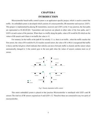
  • 1. 1 CHAPTER-1 INTRODUCTION Microcontroller based traffic control system is an application specific project, which is used to control the traffic. An embedded system is developed which consists of a microcontroller, IR transmitter and receiver, LED’s. This project is implemented by placing IR transmitters, receivers and LED’s at the 4 way junction, the four paths are represented as R1,R2,R3,R4. Transmitters and receivers are placed at either sides of the four paths, and 3 LED’s at each corner of the junction. When there is a traffic along the paths, value of R would be 00 which are the values of IR sensors and if there is no traffic the value is 11. For instance, let the traffic at the path R1 be initially 11 i.e. there is no traffic , when the traffic reaches the first sensor, the value of R would be 01,if it reaches second sensor ,the value of R is 00,it is recognized that traffic is heavy and the led glows which indicates that vehicles can move forward, traffic is cleared, and the sensor values automatically changed to 11.the control goes to the next path when the values of sensors contains more no of zeroes. Fig.1: Density dependent traffic control This entire embedded system is placed at that junction Microcontroller is interfaced with LED’s and IR sensors The total no of IR sensors required are 8 and LED’s 12. Therefore these are connected to any two ports of microcontroller.
  • 2. 2 1.1 BLOCK DIAGRAM: Fig.2: Block Diagram 1.2 BLOCK DIAGRAM DESCRIPTION: The block diagram consists of microcontroller interfaced to regulated power supply, led and IR receiver and IR transmitter which consists of an IR sensor .The IR sensors and LED’s are connected to any of the port pins of microcontroller, regulated power supply is connected to the Vcc pin of microcontroller which uses an voltage regulator to get 5 v of power supply. The transmit pin of IR receiver is connected to the receive pin of microcontroller. This embedded system is placed at the 4 way junction which controls the traffic electronically. The system uses a compact circuitry of Atmega8 Microcontroller. Programs will be developed in EMBEDDED C language. This project is implemented by placing IR transmitters, receivers. Basically an IR sensor is used for detecting an obstacle, there are some areas where valuable things are placed, an IR transmitter and receiver is placed there, an infrared path is established and if any person comes into that path the buzzer gets on which gives out a long beep Similarly a fire sensor is used to detect fire. The purpose of the transmitter is to transform the REGULATED POWER SUPPLY IR RECIEVER LED ATMEGA8 MICRO CONTROLLER IR TRANSMITTER
  • 3. 3 information we want to send into a signal that can be propagated by the channel. The receiver in this module requires the incoming data to be modulated at a particular frequency and would ignore any other IR signals. 1.3 PURPOSE OF PROJECT: The project is aimed at designing a density based dynamic traffic signal system where the timing of signal will change automatically on sensing the traffic density at any junction . The traffic lights that are in widespread use today do not do much intricate reasoning when deciding when to change the lights for the various road users waiting in different lanes. How long the signal stays green in one lane and red in another is most often determined by simple timing that is calculated when the crossing is designed. Even though today’s methods are robust and work well when the traffic load is distributed evenly across the lanes in the intersection, the systems are very inefficient because they are unable to handle various simple situations that arise throughout the day. Unnecessary waiting time in the signal can be avoided by determining in which side the green signal should be large during the traffic.
  • 4. 4 CHAPTER-2 OPERATION OF DENSITY BASED TRAFFIC LIGHT CONTROLLER 2.1 PRINCIPLE: A prototype of traffic light control system is made by using Infra-Red sensors along with major components Microcontroller and LEDs which are used for controlling traffic signals based on the density of the traffic. The junction taken into consideration is a four-side junction with the traffic flow on each side is only in one direction. This traffic light control system consists of the following three main components:  Display Unit: It consists of 3 LEDs: Green, Red and Orange on each side of the junction– a total of 12 LEDs of three colors are placed at the junction.  Detector Unit: It consists of a combined arrangement of photo diode and IR LED at every junction for detecting the presence of vehicles based on the change in resistance.  Controller Unit: This control unit contains a microcontroller which receives the output data from the IR Sensors and controls the glowing of LEDs based on the programming. This traffic light control system works on the concept of fixed time allocation at each side of the junction which cannot be changed as per varying traffic density. Timings allotted at every junction are fixed .Sometimes higher traffic density at one side of the junction demands longer time duration for green signal compared to the standard allotted time. This proposed system makes use of an Atmega8 microcontroller which is properly interfaced with the IR sensors to change the junction timing automatically to accommodate the movement of vehicles for avoiding unnecessary waste of time at each junction. The sensors used in this project IR and photo diodes are in line of sight configuration across the loads to detect the density at the traffic signal. The density of these vehicles is measured in three zones i.e., low, medium and high, respectively – based on certain time duration allotted at respective zones, accordingly. 2.2 WORKING: In this system, we will use IR sensors to measure the traffic density. We have to arrange one IR sensor for each road; these sensors always sense the traffic on that particular road. All these sensors are interfaced to the microcontroller. Based on these sensors, controller detects the traffic and controls the traffic system. The main heart of this traffic system is microcontroller.IR sensors are connected to the PORT of the microcontroller and
  • 5. 5 traffic lights are connected to PORT of microcontroller. If there is traffic on road then that particular sensor output becomes logic 0 otherwise logic1. By receiving these IR sensor outputs, we have to write the program to control the traffic system.
  • 6. 6 CHAPTER-3 CIRCUIT DISCRIPTION 3.1 CIRCUIT DIAGRAM: Fig.3: Circuit Design in Proteus The major part of this electronic system is microcontroller. All the operation are controlled by it.  Connect 12V battery or adaptor to the development board.  Switch on the supply.  Burn the program to the ATmega8 microcontroller by keeping the programming switch sw2 in program mode.  Connect four IR sensors to PORT C.  Connect LEDs to PORT B and PORT D.  Arrange all this LED’s same as like traffic lights.
  • 7. 7  Arrange one IR sensor for each road.  Now you can see the normal traffic system based on time basis.  Now if you place any obstacle in front of any IR sensor, then the system allows the traffic of that particular path by glowing GREEN light.  Finally, turn off the board power supply 3.2 COMPONENT USED:  MICROCONTROLLER (ATMEGA8)  IR SENSOR  RESISTANCE  LED  CAPACITOR  IC 555  CONNECTING WIRES 3.3 COMPONENT DISCRIPTION: 3.3.1 ATMEGA 8: The Atmel®AVR® ATmega8 is a low-power CMOS 8-bit microcontroller based on the AVR RISC architecture. By executing powerful instructions in a single clock cycle, the ATmega8 achieves throughputs approaching 1MIPS per MHz, allowing the system designer to optimize power consumption versus processing speed. PIN DISCRIPTION:  VCC: Digital supply voltage.  GND: Ground.  Port B (PB7..PB0) XTAL1/XTAL2/TOSC1/TOSC2: Port B is an 8-bit bi-directional I/O port with internal pull-up resistors (selected for each bit). ThePort B output buffers have symmetrical drive characteristics with both high sink and source capability. As inputs, Port B pins that are externally pulled low will source current if the pull-up resistors are activated. The Port B pins are tri-stated when a reset condition becomes active , even if the clock is not running. Depending on the clock selection fuse settings, PB6 can be used as input to the inverting Oscillator amplifier and input to the internal clock operating
  • 8. 8 circuit. Depending on the clock selection fuse settings, PB7 can be used as output from the inverting Oscillator amplifier. If the Internal Calibrated RC Oscillator is used as chip clock source, PB7..6 is used as TOSC2..1 input for the Asynchronous Timer/Counter2 if the AS2 bit in ASSR is set. Fig.4- Pin Diagram of ATMEGA8  Port C (PC5..PC0) : Port C is an 7-bit bi-directional I/O port with internal pull-up resistors (selected for each bit). The Port C output buffers have symmetrical drive characteristics with both high sink and source capability. As inputs, Port C pins that are externally pulled low will source current if the pull-up resistors are activated. The Port C pins are tri-stated when a reset condition becomes active, even if the clock is not running. PC6/RESET If the RSTDISBL Fuse is programmed, PC6 is used as an I/O pin. Note that the electrical characteristics of PC6 differ from those of the other pins of Port C. If the RSTDISBL Fuse is unprogrammed, PC6 is used as a Reset input. A low level on this pin for longer than the minimum pulse length will generate a Reset, even if the clock is not running. The minimum pulse length is given in Table 15 on page 38. Shorter pulses are not guaranteed to generate a Reset.  Port D (PD7..PD0): Port D is an 8-bit bi-directional I/O port with internal pull-up resistors (selected for each bit). The Port D output buffers have symmetrical drive characteristics with both high sink and source capability. As inputs, Port D pins that are externally pulled low will source current if the pull-up resistors
  • 9. 9 are activated. The Port D pins are tri-stated when a reset condition becomes active, even if the clock is not running.  RESET: Reset input. A low level on this pin for longer than the minimum pulse length will generate a reset, even if the clock is not running. Shorter pulses are not guaranteed to generate a reset.  Vcc: Vcc is the supply voltage pin for the A/D Converter, Port C (3..0), and ADC (7..6). It should be externally connected to VCC, even if the ADC is not used. If the ADC is used, it should be connected to VCC through a low-pass filter. Note that Port C (5..4) use digital supply voltage, VCC.  AREF: AREF is the analog reference pin for the A/D Converter.  ADC7..6 (TQFP and QFN/MLF Package Only): In the TQFP and QFN/MLF package, ADC7..6 serve as analog inputs to the A/D converter. These pins are powered from the analog supply and serve as 10-bit ADC channels. Features  High-performance, Low-power Atmel®AVR® 8-bit Microcontroller  Advanced RISC Architecture – 130 Powerful Instructions – Most Single-clock Cycle Execution – 32 × 8 General Purpose Working Registers – Fully Static Operation – Up to 16MIPS Throughput at 16MHz – On-chip 2-cycle Multiplier  High Endurance Non-volatile Memory segments – 8Kbytes of In-System Self-programmable Flash program memory – 512Bytes EEPROM – 1Kbyte Internal SRAM – Write/Erase Cycles: 10,000 Flash/100,000 EEPROM – Data retention: 20 years at 85°C/100 years at 25°C(1) – Optional Boot Code Section with Independent Lock Bits. In-System Programming by – On-chip Boot Program. True Read-While-Write Operation – Programming Lock for Software Security  Peripheral Features – Two 8-bit Timer/Counters with Separate Pre scaler, one Compare Mode
  • 10. 10 – One 16-bit Timer/Counter with Separate Pre scaler, Compare Mode, and Capture. Mode – Real Time Counter with Separate Oscillator – Three PWM Channels – 8-channel ADC in TQFP and QFN/MLF package  Eight Channels 10-bit Accuracy – 6-channel ADC in PDIP package. Six Channels 10-bit Accuracy – Byte-oriented Two-wire Serial Interface – Programmable Serial USART – Master/Slave SPI Serial Interface – Programmable Watchdog Timer with Separate On-chip Oscillator – On-chip Analog Comparator  Special Microcontroller Features – Power-on Reset and Programmable Brown-out Detection – Internal Calibrated RC Oscillator – External and Internal Interrupt Sources – Five Sleep Modes: Idle, ADC Noise Reduction, Power-save, Power-down, and Standby  I/O and Packages – 23 Programmable I/O Lines – 28-lead PDIP, 32-lead TQFP, and 32-pad QFN/MLF  Operating Voltages – 2.7V - 5.5V (ATmega8L) – 4.5V - 5.5V (ATmega8)  Speed Grades – 0 - 8MHz (ATmega8L) – 0 - 16MHz (ATmega8)  Power Consumption at 4Mhz, 3V, 25 degreeC – Active: 3.6mA – Idle Mode: 1.0mA – Power-down Mode: 0.5µA
  • 11. 11 3.3.2 IR SENSOR IR (INFRARED) sensor is based on LM 358 IC which is an Operational amplifier acting as comparator. The comparator compares the analog voltages of potentiometer and the voltage generated by the photodiode. The two voltages are applied on the two terminals of the IC and correspondingly it generates a digital output on the output pin that is indicated by a Red LED. The IR sensor is compatible with various microcontroller boards like 8051, Arduino , pic etc. This shield is based on the working of a circuit comprising op-amp, an IR led and photodiode the output generate by the sensor is due the comparator action of the op amp (LM358). The Compares the two voltages that is generated by the photodiode and the potentiometer. When the value of voltage Vd generated by photodiode is greater than the voltage set on the potentiometer, the output is HIGH and vice versa. Fig:5 IR sensor Technical Specifications:  2-12cm range  Potentiometer for maximum range setting can be used to differentiate between black and white (Can be used for line sensing) .  Onboard LED indication for detection  Works on 5V input.  TTL compatible output .  LM358 IC (Integrated Circuit) that acts as a comparator/ ADC (Analog to Digital Converter) IC which makes it digital sensor.
  • 12. 12 IR Transmitter and Receiver The purpose of the transmitter is to transform the information we want to send into a signal that can be propagated by the channel. In the case of our wired copper channel, this means we want the information to be transformed into a modulated voltage level, something like the pulse train. For a wireless channel, however, the transmitter needs to encode the information onto an EM wave that can be easily propagated. IR Transmitter: The IR transmitter part consists of an Infra red light emitting diode that can capable of sending modulated data within infra red band. To match the receiver frequency the data is modulated at 38.7 KHZ by configuring 555 timer at astable mode of operation, which generates frequency using the components R2 and C2 as shown in above fig. This frequency can be varied over a long range just by varying the preset R1 and C1. Fig.6: IR Transmitter circuit IR Receiver: The IR receiver consists of TSOP 1738 module which is a simple yet effective IR proximity sensor built around the TSOP 1738 module. The TSOP module is commonly found at the receiving end of an IR remote control system; e.g., in TVs, CD players etc. These modules require the incoming data to be modulated at a particular frequency and would ignore any other IR signals. It is also immune to ambient IR light, so one can easily use these sensors outdoors or under heavily lit conditions. Such modules are available for different carrier frequencies from 32 kHz to 42kHz. In this particular proximity sensor, we will be generating a constant stream of square wave signal using IC555 centered at 38 kHz and would use it to drive an IR led. So whenever this signal bounces off the obstacles, the receiver would detect it and change its output. Since the TSOP 1738 module works in the active-low configuration, its output would normally remain high and would go low when it detects the signal (the obstacle). Basically an IR sensor is used for detecting an obstacle, there are some areas where valuable things are placed, an IR transmitter and receiver is placed there, an infrared path is established and if any person comes into that path the buzzer gets on which gives out a long beep Similarly a fire sensor is used to detect fire
  • 13. 13 The sensed data is given to the microcontroller, processing is done according to the logic in the microcontroller and then writes onto GSM which will further send sms to the mobile at the user A buzzer is interfaced to microcontroller to give out a beep sound whenever an obstacle and fire is detected. Fig.7: IR Receiver Circuit 3.3.3 RESISTOR: The electrical resistance of an electrical conductor is the opposition to the passage of an electric current through that conductor. The inverse quantity is electrical conductance, the ease with which an electric current passes. Electrical resistance shares some conceptual parallels with the notion of mechanical friction. The SI unit of electrical resistance is the ohm (Ω), while electrical conductance is measured in siemens (S). An object of uniform cross section has a resistance proportional to its resistivity and length and inversely proportional to its cross-sectional area. All materials show some resistance, except for superconductors, which have a resistance of zero. Fig.8: Resistor
  • 14. 14 3.3.4 LED: A light-emitting diode (LED) is a two-lead semiconductor HYPERLINK light source. It is a pnjunction HYPERLIN diode, which emits light when activated. When a suitable voltage is applied to the leads, electrons are able to recombine with electron holes within the device, releasing energy in the form of photons. This effect is called electroluminescence, and the color of the light (corresponding to the energy of the photon) is determined by the energy band gap of the semiconductor. Fig.9: LED 3.3.5 CAPACITOR: Capacitors are electronic devices which essentially store energy as an electrostatic field, and are composed of an insulating material placed between two conductive plates. In PCBs, they can block the flow of direct current while enabling the flow of indirect current. When DC voltage is applied to a capacitor, the electric charge is stored by each conductive plate. Current flows while the capacitor is storing energy—when the capacitor is full, current stops flowing. The type of material used as the insulating material (a dielectric material) determines capacitor type. Common insulator materials include ceramic, polycarbonate and silver mica. In PCBs, the board itself often creates a capacitor, with alternating layers of metal conductive areas, ground conductor and powder conductor, creating a stable capacitor. Within PCBs, decoupling capacitors can be found, which serve to reduce the noise and effects of other elements on the rest of the circuit board by routing such noise through the capacitor which can then store the excess energy. To test a capacitor in a PCB, one end of the capacitor should be removed from the circuit. The power supply of DC voltage should match the range of the capacitor so as not to overload the device. When voltage is applied several outcomes are possible: if the capacitor has shorted the meter will simply reflect the output voltage of the power supply; if the capacitor is leaking the meter reading will jump high and then drop low again (but not
  • 15. 15 all the way to zero); if the meter registers no jump at all, the capacitor is either open or capacitance is too low to register a result. Fig.10.Capacitor 3.3.6 IC555 The 555 timer IC is an integrated circuit (chip) used in a variety of timer, pulse generation, and oscillator applications. The 555 can be used to provide time delays, as an oscillator, and as a flip-flop element. Derivatives provide two or four timing circuits in one package. PIN DISCRIPTION: GND Ground reference voltage, low level (0 V) TRIG The OUT pin goes high and a timing interval starts when this input falls below 1/2 of CTRL voltage (which is typically 1/3 VCC, CTRL being 2/3 VCC by default if CTRL is left open). More simply we can say that OUT will be high as long as the trigger is kept at low voltage. Output of the timer totally depends upon the amplitude of the external trigger voltage applied to this pin. OUT This output is driven to approximately 1.7 V below +VCC, or to GND. RESET A timing interval may be reset by driving this input to GND, but the timing does not begin again until RESET rises above approximately 0.7 volts. Overrides TRIG which overrides THR. CTRL Provides "control" access to the internal voltage divider (by default, 2/3 VCC).
  • 16. 16 THR The timing (OUT high) interval ends when the voltage at THR ("threshold") is greater than that at CTRL (2/3 VCC if CTRL is open). DIS Open collector output which may discharge a capacitor between intervals. In phase with output. VCC Positive supply voltage, which is usually between 3 and 15 V depending on the variation. Fig.11 IC 555 3.3.7 LDR A photoresistor or light-dependent resistor (LDR) or photocell is a light-controlled variable resistor. The resistance of a photoresistor decreases with increasing incident light intensity; in other words, it exhibits photoconductivity. A photoresistor can be applied in light-sensitive detector circuits, and light- and dark-activated switching circuits. A photoresistor is made of a high resistance semiconductor. In the dark, a photoresistor can have a resistance as high as a few mega ohms (MΩ), while in the light, a photoresistor can have a resistance as low as a few hundred ohms. If incident light on a photoresistor exceeds a certain frequency, photons absorbed by the semiconductor give bound electrons enough energy to jump into the conduction band. The resulting free electrons (and its hole partners) conduct electricity, thereby lowering resistance. Fig.12 LDR
  • 17. 17 CHAPTER-4 SOFTWARE USASGE 4.1 INSTALLING TOOLS FOR C PROGRAMMING: To work with the Atmel AVR microcontroller using the C programming language, two tools are required: AVR Studio and AVR. 1. AVR Studio is an integrated development environment that includes an editor, the assembler, HEX file downloader and a microcontroller emulator. 2. ICC AVR is for a ICC-based compiler for AVR. It appears in AVR Studio as a plugin. ICC AVR also includes a program called Programmer’s Notepad that can be used to edit and compile C programs, independently of AVR Studio. Installing these tools is easy, just download and run the setup files, and accept the default installation options. Remember to install AVR Studio first before ICC-AVR. 3. It supports inline assembly and can interface with assembly modules. 4. It supports all AT90S and Atmega devices and AT94K FPSLIC. 5. Modern IDE with code folding, workspace and project management, one click access to function definitions, etc . Fig.13: AVR studio
  • 18. 18 4.2 USING AVR STUDIO FOR C PROGRAMMING: After creating a simple C program for the Atmel AVR you will be guided through four major stages: 1. Creating an AVR Studio project. 2. Compiling C code to HEX file. 3. Debugging C program using the simulator. 4. Downloading HEX file to the proteus software and simulating it. 4.4.1 CREATING AN ICC AVR PROJECT: Perform the following steps to create a simple AVR project. 1. Start the ICC AVR program by selecting atmega 8 from application builder. 2. Select Project | New Project. In the dialog box that appears and specify the project name and project location. If options ‘Create new file’, an empty C file and will be created for you. In this case, we create a file called ‘led’. 3. In the ‘Select debug platform and device’ dialog that appears choose ‘AVR Simulator’ as the debug platform and ‘ATMEGA32’ as the device. Click button Finish. 4. A project file will be created and ICC AVR displays an empty file led.. Enter the C code. Fig 14: The ICC AVR with a project file open.
  • 19. 19 4.4.2 COMPILING C CODE TO HEX FILE: 1. Click menu Build | Rebuild All to compile the C code. 2. If there is no error message, a file called led.hex will be produced .This file contains the machine code that is ready to be downloaded to the ATMEGA32 microcontroller. The file is stored in sub-folder ‘default’ of your project. 3. If there are error messages, check your C code. Most often, they are caused by some typos or syntax errors. 4. And after checking this program, burn on burner kit so that hardware can work Fig 15: Compiling code 5. While debugging the C program, you can change the contents of a register. For example, to change Port A Input Pins register (PINA), click on the value column of PINA and enter a new value This change takes effect immediately. Subsequently, the contents of PORTB will be 0x04 after running the two C instruction. 6. To monitor a C variable, select the variable name in the code window and click menu. 7. Debug | Quick Watch. The variable will be added to a watch window. 4.4.3 SIMULATION PROCESS : 1. Proteus8.1 is best simulation software for various designs with microcontroller.
  • 20. 20 2. It is a handy tool to test programs and embedded designs for electronics hobbyist. 3. Basically PROTEUS is also simulating software but it helps you attach many components with the 8051. Like resistors, capacitors, LEDs, LCDs, keypads, ICs etc. and these are just few that I have named in general. It has a complete library and you will find everything that you will ever need. You can design your complete circuit and then simulate it to view the final output. This means that after perfecting your project on the programming side in KEIL, you'll need to simulate it on PROTEUS to determine the output of the hardware components and change it if need be. This will completely ensure your project's success 4. Open the Proteus and then create a new project by clicking on new project button. 5. Now give a Name to our project and do not change anything, just follow the default options and click Next until you see Finish button. 6. Draw the circuit diagram by clicking on Schematic Capture button and then add the components by Click P button followed by Component button under Devices for picking components. 7. Choose your component by simply typing the name at Keyword box. After selecting item click OK and the selected components will listed under Devices. 8. Now draw the circuit diagram i.e. make the connection. 9. Simulate the circuit by clicking on run button. Fig.16: Output when simulation start on proteus
  • 21. 21 4.5 PROGRAMMING: #define F_CPU 8000000UL #include <avr/io.h> #include <util/delay.h> #define R1 PB0 #define Y1 PB1 #define G1 PB2 #define R2 PB3 #define Y2 PB4 #define G2 PB5 #define R3 PD5 #define Y3 PD4 #define G3 PD3 #define R4 PD2 #define Y4 PD1 #define G4 PD0 int main(void) { DDRB = 0xff; DDRD = 0xff; DDRC = 0x00; PORTB = 0x00; PORTD = 0x00; while(1) {
  • 22. 22 if((PINC&0x01) == 0x01) { PORTB |= (1<<G1); PORTB |= (1<<Y2); PORTD |= (1<<R3); PORTD |= (1<<R4); } else if((PINC&0x02) == 0x02) { PORTB |= (1<<R1); PORTB |= (1<<G2); PORTD |= (1<<Y3); PORTD |= (1<<R4); } else if((PINC&0x04) == 0x04) { PORTB |= (1<<R1); PORTB |= (1<<R2); PORTD |= (1<<G3); PORTD |= (1<<Y4); } else if((PINC&0x08) == 0x08) { PORTB |= (1<<Y1); PORTB |= (1<<R2);
  • 23. 23 PORTD |= (1<<R3); PORTD |= (1<<G4); } else { PORTB = 0x00; PORTD = 0x00; PORTB |= (1<<G1); PORTB |= (1<<Y2); PORTD |= (1<<R3); PORTD |= (1<<R4); _delay_ms(7000); PORTB = 0x00; PORTD = 0x00; PORTB |= (1<<R1); PORTB |= (1<<G2); PORTD |= (1<<Y3); PORTD |= (1<<R4); _delay_ms(7000); PORTB = 0x00; PORTD = 0x00; PORTB |= (1<<R1); PORTB |= (1<<R2); PORTD |= (1<<G3); PORTD |= (1<<Y4);
  • 24. 24 _delay_ms(7000); PORTB = 0x00; PORTD = 0x00; PORTB |= (1<<Y1); PORTB |= (1<<R2); PORTD |= (1<<R3); PORTD |= (1<<G4); _delay_ms(7000); PORTB = 0x00; PORTD = 0x00; } } }