1. EGR/CS 332: COMPUTER ORGANIZATION AND ARCHITECTURE
LOGISIM ETHERNET MAC ADDRESS READER
Muntabir Choudhury and Minh Doan
Department of Physics and Engineering
Elizabethtown College, Elizabethtown, PA
Email: doanm@etown.edu & choudhurym@etown.edu
ABSTRACT
Our task was to do a project which could be involved hardware,
software, logic gate design or any research project that could be
feasible to build in future. According to the learning outcomes
we have learned Boolean algebra, design of combinational and
sequential circuits and their use in von Neumann computer
architecture and also basic concepts of computer systems such
that memory, control, I/O system. Therefore, to meet the
concession of our project, we have decided to design a circuit
which is able to read source and destination mac address and
display the mac address into the twenty four seven segment
display.
INTRODUCTION
In 1971, Metcalfe and his Xerox PARC colleagues developed
the first experimental Ethernet system to interconnect the Xerox
Alto, a personal workstation with graphical user interface. The
signal clock for the experimental Ethernet interface was derived
from Alto’s system clock, which resulted in data transmission
rate on the experimental Ethernet of 2.94 Mbps. In 1973,
Metcalfe changed the name of his first experimental network
“Alto Aloha” to “Ethernet”, to make it clear that the system
could support any computer-not just Altos-and to point out that
his new network mechanism had evolved well beyond the
Aloha system. The necessity of the Ethernet includes low cost,
ease of use, protocol neutrality, good connectivity and simple
migration to higher speed networks. For this project we will use
the first layer of Ethernet packet which includes 4 steps-
Preamble, SFD (start frame delimiter), Destination Address and
Source Address –to implement into the Logisim by using logic
gates, flip-flop to display the MAC address into twenty four
seven segment display.
CONCEPTS
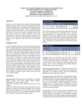
Ethernet Frame: Transmitted data is embedded in a container,
called a frame. This Frame format defines Ethernet.
Historically, two types of frames existed:
-IEEE 802.3 Framing used a length field after the Source
Address
-Ethernet II (DIX) Framing used a type field after the Source
Address. It consists of an eight-byte preamble, six byte source
and destination addresses, a two type field used to identify
higher layer protocols, and a variable data byte field followed
by a four-byte FCD (frame check sequence) field.
Now, both frame types are defined and supported within IEEE
802.3 and frame divides the preamble into a seven-byte
preamble followed by a single byte start of frame delimiter
(SFD). The two-byte type field now becomes a two-byte length
field. The data field now includes an 802.2 logical link control
(LLC) field that precedes the actual data. The FCS remains the
same. According to our project goal we will stick until source
address.
Preamble: Since we will follow the IEEE 802.3 Ethernet
Frame, therefore the preamble of an Ethernet packet consists of
a 56-bit (seven-byte) pattern of alternating 1 and 0 bits,
allowing devices on the network to easily synchronize their
receiver clocks, which is followed by Start Frame Delimiter
(SFD) to mark a new incoming frame.
Start Frame Delimiter (SFD): The SFD is the 8-bit (one byte)
value marking the end of the preamble and indicating the
beginning of the Ethernet Frame. The SFD immediately
followed by the destination MAC address.
Destination Address: The IEEE 802.3 standard further defines
the second bit of the 48-bit (six byte) destination to indicate
whether the address is logically administrated or globally. This
bit is a “0” when the address is globally administrated; that is,
assigned by the Ethernet interface manufacturer. A 48-bit
address of all 1’s is a broadcast address in both DIX-Ethernet II
and IEEE formats, indicating that the transmission is directed
to all devices on the network.
Source Address: The 48-bit source address is appended to the
transmission as an aid to the higher layer protocols. It is not
used for medium access control. To avoid duplicate node IDs
for global addresses, the Ethernet adapter manufacturer obtains
an Organizationally Unique Identifier (OUI) from the IEEE (for
2. an administration fee). The OUI is 24-bits long and is used as
the most significant portion of the 48-bit address. The
manufacturer, using good record keeping, will assign sequential
numbers to each adapter card he makes thereby creating a
worldwide unique address. With 24-bits to work with, a lot of
adapters can be produced from a single manufacturer. A list of
OUI assignments can be found on the Internet.
METHODOLOGY
We used d flipflops as shift register to store 160 bits in order of
a queue. If the first 64 bits entered into the queue matches the
preamble sequence, then the next 96 bits must be the source and
destination mac address. So we designed a simple And logic
check with the preamble sequence (Appendix A)
And then the source and MAC address can be displayed on
seven segment display immediately (Appendix B)
The display logic circuit has a switch which connects directly
to the output of the preamble sequence check so the seven
segment display will only powered on when a preamble is
detected (Appendix C)
CONCLUSION
To implement the circuits into the Logisim we need to be very
careful to tie the wire with 4-bit shift register and seven segment
display because the wire can easily be cross connected with
another and the resulting value would be null. On another hand,
this project meets the two areas of concentration such that
networking and hardware. The learning outcomes of this
project that one can understand the basic idea of Ethernet Frame
while studying the Boolean Algebra, Logic Gates, Sequential
& Combinational circuits at the same time.
REFERENCES
standards.ieee.org
www.us.ntt.net
www.iol.unh.edu
www.industrialethernetu.com
APPENDICES
Appendix A: And Logic Check
Appendix B: Seven Segment Display
Appendix C: Seven Segment Display 2
Appendix D: Full implementation