SlideShare a Scribd company logo
1 of 8
The Ethernet Frame:A walkthrough
The Ethernet Frame
The organization of the Ethernet frame is central to the operation of the system. The Ethernet
standard determines both the structure of a frame and when a station is allowed to send a frame. The
frame was first defined in the original Ethernet DEC-Intel-Xerox (DIX) standard, and was later redefined
and modified in the IEEE 802.3 standard. The changes between the two standards were mostly
cosmetic, except for the type or length field.
The DIX standard defined a type field in the frame. The first 802.3 standard (published in 1985)
specified this field as a length field, with a mechanism that allowed both versions of frames to coexist
on the same Ethernet system. Most networking software kept using the type field version of the frame.
A later version of the IEEE 802.3 standard was changed to define this field of the frame as being either
length or type, depending on usage.
Figure 1-1 shows the DIX and IEEE versions of the Ethernet frame. There are three sizes of frame
currently defined in the standard, and a given Ethernet interface must support at least one of them.
The standard recommends that new implementations support the most recent frame definition, called
anenvelope frame, which has a maximum size of 2,000 bytes. The two other sizes are basic frames,
with a maximum size of 1,518 bytes, and Q-tagged frameswith a maximum of 1,522 bytes.
Figure 1-1. DIX Ethernet and IEEE 802.3 frames
Because the DIX and IEEE basic frames both have a maximum size of 1,518 bytes and are identical in
terms of the number and length of fields, Ethernet interfaces can send either DIX or IEEE basic frames.
The only difference in these frames is in the contents of the fields and the subsequent interpretation of
those contents by the network interface software.
Now, we’ll take a detailed tour of the frame fields.
Preamble
The frame begins with the 64-bit preamble field, which was originally incorporated to allow 10 Mb/s
Ethernet interfaces to synchronize with the incoming data stream before the fields relevant to carrying
the content arrived.
The preamble was initially provided to allow for the loss of a few bits due to signal start- up delays as
the signal propagates through a cabling system. Like the heat shield of a spacecraft, which protects the
spacecraft from burning up during reentry, the preamble was originally developed as a shield to
protect the bits in the rest of the frame when operating at 10 Mb/s.
The original 10 Mb/s cabling systems could include long stretches of coaxial cables, joined by signal
repeaters. The preamble ensures that the entire path has enough time to start up, so that signals are
re‐ ceived reliably for the rest of the frame.
The higher-speed Ethernet systems use more complex mechanisms for encoding the signals that avoid
any signal start-up losses, and these systems don’t need a preamble to protect the frame signals.
However, it is maintained for backward compatibility with the original Ethernet frame and to provide
some extra timing for interframe house‐ keeping, as demonstrated, for example, in the 40 Gb/s
system.
While there are differences in how the two standards formally defined the preamble bits, there is no
practical difference between the DIX and IEEE preambles. The pattern of bits being sent is identical:
DIX standard
In the DIX standard, the preamble consists of eight “octets,” or 8-bit bytes. The first seven comprise a
sequence of alternating ones and zeros. The eighth byte of the preamble contains 6 bits of alternating
ones and zeros, but ends with the special pattern of “1, 1.” These two bits signal to the receiving
interface that the end of the preamble has been reached, and that the bits that follow are the actual
fields of the frame.
IEEE standard
In the 802.3 specification, the preamble field is formally divided into two parts consisting of seven
bytes of preamble and one byte called the start frame delimit‐ er (SFD). The last two bits of the SFD
are 1, 1, as with the DIX standard.
Destination Address
The destination address field follows the preamble. Each Ethernet interface is assigned a unique 48-bit
address, called the interface’s physical or hardware address. The desti‐nation address field contains
either the 48-bit Ethernet address that corresponds to the address of the interface in the station that is
the destination of the frame, a 48-bit mul‐ ticast address, or the broadcast address.
Ethernet interfaces read in every frame up through at least the destination address field. If the
destination address does not match the interface’s own Ethernet address, or one of the multicast or
broadcast addresses that the interface is programmed to receive, then the interface is free to ignore
the rest of the frame. Here is how the two standards implement destination addresses:
DIX standard
The first bit of the destination address, as sent onto the network medium, is used to distinguish
physical addresses from multicast addresses. If the first bit is zero, then the address is the physical
address of an interface, which is also known as a unicast address, because a frame sent to this address
only goes to one destination. If the first bit of the address is a one, then the frame is being sent to
a multicast address. If all 48 bits are ones, this indicates the broadcast, or all-stations, address.
IEEE standard
The IEEE 802.3 version of the frame adds significance to the second bit of the destination address,
which is used to distinguish between locally and globallyad‐ ministered addresses. A globally
administered address is a physical address assigned to the interface by the manufacturer, which is
indicated by setting the second bit to zero. (DIX Ethernet addresses are always globally administered.)
If the address of the Ethernet interface is administered locally for some reason, then the second bit is
supposed to be set to a value of one. In the case of a broadcast address, the second bit and all other
bits are ones in both the DIX and IEEE standards.
Locally administered addresses are rarely used on Ethernet systems, because each Ethernet interfaces
is assigned its own unique 48-bit address at the factory. Locally administered addresses, however, were
used on some other local area network systems.
Understanding physical addresses
In Ethernet, the 48-bit physical address is written as 12 hexadecimal digits with the digits paired in
groups of two, representing an octet (8 bits) of information. The octet order of transmission on the
Ethernet is from the leftmost octet (as written or displayed) to the rightmost octet. The actual
transmission order of bits within the octet, however, goes from the least significant bit of the octet
through to the most significant bit.
This means that an Ethernet address that is written as the hexadecimal string F0-2E-15-6C-77-9B is
equivalent to the following sequence of bits, sent over the Ether‐net channel from left to right:
0000 1111 0111 0100 1010 1000 0011 0110 1110 11101101 1001.
Therefore, the 48-bit destination address that begins with the hexadecimal value 0xF0 is a unicast
address, because the first bit sent on the channel is a zero.
Source Address
The next field in the frame is the source address. This is the physical address of the device that sent
the frame. The source address is not interpreted in any way by the Ethernet MAC protocol, although it
must always be the unicast address of the device sending the frame. It is provided for the use of high-
level network protocols, and as an aid in troubleshooting. It is also used by switches to build a table
associating source addresses with switch ports. An Ethernet station uses its physical address as the
source address in any frame it transmits.
The DIX standard notes that a station can change the Ethernet source address, while the IEEE standard
does not specifically state that an interface may have the ability to override the 48-bit physical address
assigned by the manufacturer. However, all Ethernet interfaces in use these days appear to allow the
physical address to be changed, which makes it possible for the network administrator or the high-level
network software to modify the Ethernet interface address if necessary.
To provide the physical address used in the source address field, a vendor of Ethernet equipment
acquires an organizationally unique identifier (OUI), which is a unique 24- bit identifier assigned by the
IEEE. The OUI forms the first half of the physical address of any Ethernet interface that the vendor
manufactures. As each interface is manufac‐ tured, the vendor also assigns a unique address to the
interface using the second 24 bits of the 48-bit address space, and that, combined with the OUI,
creates the 48-bit address. The OUI may make it possible to identify the vendor of the interface chip,
which can sometimes be helpful when troubleshooting network problems.
Q-Tag
The Q-tag is so called because it carries an 802.1Q tag, also known as a VLAN or priority tag. The
802.1Q standard defines a virtual LAN (VLAN) as one or more switch ports that function as a separate
and independent Ethernet system on a switch. Ethernet traffic within a given VLAN (e.g., VLAN 100)
will be sent and received only on those ports of the switch that are defined to be members of that
particular VLAN (in this case, VLAN 100). A 4-byte-long Q-tag is inserted in an Ethernet frame between
the source address and the length/type field to identify the VLAN to which the frame belongs. When a
Q- Tag is present, the minimum data field size is reduced to 42 bytes, maintaining a min‐ imum frame
size of 64 bytes.
Switches can be connected together with an Ethernet segment that functions as a trunk connection
that carries Ethernet frames with VLAN tags in them. That, in turn, makes it possible for Ethernet
frames belonging to VLAN 100, for example, to be carried be‐ tween multiple switches and sent or
received on switch ports that are assigned to VLAN 100.
VLAN tagging, a vendor innovation, was originally accomplished using a variety of proprietary
approaches. Development of the IEEE 802.1Q standard for virtual bridged LANs produced the VLAN tag
as a vendor-neutral mechanism for identifying which VLAN a frame belongs to.
The addition of the 4-byte VLAN tag causes the maximum size of an Ethernet frame to be extended
from the original maximum of 1,518 bytes (not including the preamble) to a new maximum of 1,522
bytes. Because VLAN tags are only added to Ethernet frames by switches and other devices that have
been programmed to send and receive VLAN- tagged frames, this does not affect traditional, or
“classic,” Ethernet operation.
The first two bytes of the Q-tag contain an Ethernet type identifier of 0x8100. If an Ethernet station
that is not programmed to send or receive a VLAN tagged frame hap‐ pens to receive a tagged frame, it
will see what looks like a type identifier for an unknown protocol type and simply discard the frame.
Envelope Prefix and Suffix
As networks grew in complexity and features, the IEEE received requests for more tags to achieve new
goals. The VLAN tag provided space for a VLAN ID and Class of Service (CoS) bits, but vendors and
standards groups wanted to add extra tags to support new bridging features and other schemes.
To accommodate these requests, the 802.3 standards engineers defined an “envelope frame,” which
adds an extra 482 bytes to the maximum frame size. The envelope frame was specified in the 802.3as
supplement to the standard, adopted in 2006. In another change, the tag data was added to the data
field to produce a MAC Client Data field. Because the MAC client data field includes the tagging fields,
it may seem like the frame size definition has changed, but in fact this is just a way of referring to the
combination of tag data and the data field for the purpose of defining the envelope frame.
The 802.3as supplement modified the standard to state that an Ethernet implementation should
support at least one of three maximum MAC client data field sizes. The data field size continues to be
defined as 46 to 1,500 bytes, but to that is added the tagging infor‐ mation to create the MAC client
data field, resulting in the following MAC client data field sizes:
 1,500-byte “basic frames” (no tagging information)1,982-byte “envelope frames” (1,500-byte
data field plus 482 bytes for all tags)
 1,504-byte “Q-tagged frames” (1,500-byte data field plus 4-byte tag)
The contents of the tag space are not defined in the Ethernet standard, allowing maxi‐ mum flexibility
for the other standards to provide tags in Ethernet frames. Either or both prefix and suffix tags can be
used in a given frame, occupying a maximum tag space of 482 bytes if either or both are present. This
can result in a maximum frame size of 2,000 bytes.
The latest standard simply includes the Q-tag as one of the tags that can be carried in an envelope
prefix. The standard notes, “All Q-tagged frames are envelope frames, but not all envelope frames are
Q-tagged frames.” In other words, you can use the envelope space for any kind of tagging, and if you
use a Q-tag, then it is carried in the envelope prefix as defined in the latest standard. An envelope
frame carrying a Q-tag will have a minimum data size of 42 bytes, preserving the minimum frame size
of 64 bytes.
Tagged frames are typically sent between switch ports that have been configured to add and remove
tags as necessary to achieve their goals. Those goals can include VLAN operations and tagging a frame
as a member of a given VLAN, or more complex tagging schemes to provide information for use by
higher-level switching and routing protocols. Normal stations typically send basic Ethernet frames
without tags, and will drop tagged frames that they are not configured to accept.
Type or Length Field
The old DIX standard and the IEEE standard implement the type and/or length fields differently:
DIX standard
In the DIX Ethernet standard, this 16-bit field is called a type field, and it always contains an identifier
that refers to the type of high-level protocol data being carried in the data field of the Ethernet frame.
For example, the hexadecimal value 0x0800 has been assigned as the identifier for the Internet
Protocol (IP). A DIX frame being used to carry an IP packet is sent with the value of 0x0800 in the type
field of the frame. All IP packets are carried in frames with this value in the type field.
IEEE standard
When the IEEE 802.3 standard was first published in 1985, the type field was not included, and instead
the IEEE specifications called this field a length field. Type fields were added to the IEEE 802.3
standard in 1997, so the use of a type field in the frame is officially recognized in 802.3. This change
simply made the common practice of using the type field an official part of the standard. The
identifiers used in the type field were originally assigned and maintained by Xerox, but with the type
field now part of the IEEE standard, the responsibility for assigning type num‐ bers was transferred to
the IEEE.
In the IEEE 802.3 standard, this field is called a length/type field, and the hexadecimal value in the
field indicates the manner in which the field is being used. The first octet of the field is considered the
most significant octet in terms of numeric value.
If the value in this field is numerically less than or equal to 1,500 (decimal), then the field is being
used as a length field. In that case, the value in the field indicates the number of logical link control
(LLC) data octets that follow in the data field of the frame. If the number of LLC octets is less than the
minimum required for the data field of the frame, then octets of padding data will automatically be
added to make the data field large enough. The content of the padding data is unspecified by the
standard. Upon reception of the frame, the length field is used to determine the length of valid data in
the data field, and the padding data is discarded.
If the value in this field of the frame is numerically greater than or equal to 1,536 decimal (0x600 hex),
then the field is being used as a type field.The range of 1,501 to 1,535 was intentionally left undefined
in the standard.
In that case, the hexadecimal identifier in the field is used to indicate the type of protocol data being
carried in the data field of the frame. The network software on the station is responsible for providing
any padding data required to ensure that the data field is 46 bytes in length. With this method, there is
no conflict or ambiguity about whether the field indicates length or type.
Data Field
Next comes the data field of the frame, which is also treated differently in the two standards:
DIX standard
In a DIX frame, this field must contain a minimum of 46 bytes of data, and may range up to a maximum
of 1,500 bytes of data. The network protocol software is expected to provide at least 46 bytes of data.
IEEE standard
The total size of the data field in an IEEE 802.3 frame is the same as in a DIX frame: a minimum of 46
bytes and a maximum of 1,500. However, a logical link control protocol defined in the IEEE 802.2 LLC
standard may ride in the data field of the 802.3 frame to provide control information. The LLC protocol
is also used as a way to identify the type of protocol data being carried by the frame if the type/length
field is used for length information. The LLC protocol data unit (PDU) is carried in the first set of bytes
in the data field of the IEEE frame. The structure of the LLC PDU is defined in the IEEE 802.2 LLC
standard.
The process of figuring out which protocol software stack gets the data in an incoming frame is known
as demultiplexing. An Ethernet frame may use the type field to identify the high-level protocol data
being carried by the frame. In the LLC specification, the receiving station demultiplexes the frame by
deciphering the contents of the logical link control protocol data unit.
FCS Field
The last field in both the DIX and IEEE frames is the frame check sequence (FCS) field, also called the
cyclic redundancy check (CRC). This 32-bit field contains a value that is used to check the integrity of
the various bits in the frame fields (not including the preamble/SFD). This value is computed using the
CRC, a polynomial that is calculated using the contents of the destination, source, type (or length),
and data fields. As the frame is generated by the transmitting station, the CRC value is simultaneously
being calculated. The 32 bits of the CRC value that are the result of this calculation are placed in the
FCS field as the frame is sent. The x31 coefficient of the CRC polynomial is sent as the first bit of the
field, and the x0 coefficient as the last.
The CRC is calculated again by the interface in the receiving station as the frame is read in. The result
of this second calculation is compared with the value sent in the FCS field by the originating station. If
the two values are identical, then the receiving station is provided with a high level of assurance that
no errors have occurred during transmission over the Ethernet channel. If the values are not identical,
then the interface can discard the frame and increment the frame error counter.
End of Frame Detection
The presence of a signal on the Ethernet channel is known as carrier. The transmitting interface stops
sending data after the last bit of a frame is transmitted, which causes the Ethernet channel to become
idle. In the original 10 Mb/s system, the loss of carrier when the channel goes idle signals to the
receiving interface that the frame has ended. When the interface detects loss of carrier, it knows that
the frame transmission has come to an end. The higher-speed Ethernet systems use more complex
signal encoding schemes, which have special symbols available for signaling to the interface the start
and end of a frame.
A basic frame carrying a maximum data field of 1,500 bytes is actually 1,518 bytes in length (not
including the preamble) when the 18 bytes needed for the addresses, length/ type field, and the frame
check sequence are included. The addition of a further 482 bytes for envelope frames makes the
maximum frame size become 2,000 bytes. This was chosen as a useful maximum frame size that could
be handled by a typical Ethernet implementation in an interface or switch port, while providing enough
room for current and future prefixes and suffixes.

More Related Content

What's hot

I2C Bus (Inter-Integrated Circuit)
I2C Bus (Inter-Integrated Circuit)I2C Bus (Inter-Integrated Circuit)
I2C Bus (Inter-Integrated Circuit)Varun Mahajan
 
Ethernet Computer network
Ethernet Computer networkEthernet Computer network
Ethernet Computer networkmiteshppt
 
STP (spanning tree protocol)
STP (spanning tree protocol)STP (spanning tree protocol)
STP (spanning tree protocol)Netwax Lab
 
6lowpan 110828234426-phpapp01
6lowpan 110828234426-phpapp016lowpan 110828234426-phpapp01
6lowpan 110828234426-phpapp01mrmr2010i
 
CCNA Basic Switching and Switch Configuration
CCNA Basic Switching and Switch ConfigurationCCNA Basic Switching and Switch Configuration
CCNA Basic Switching and Switch ConfigurationDsunte Wilson
 
Introduction to network switches
Introduction to network switchesIntroduction to network switches
Introduction to network switchesNetProtocol Xpert
 
CCNA Course Training Presentation
CCNA Course Training PresentationCCNA Course Training Presentation
CCNA Course Training PresentationRohit Singh
 
Link Aggregation Control Protocol
Link Aggregation Control ProtocolLink Aggregation Control Protocol
Link Aggregation Control ProtocolKashif Latif
 
Ccna ppt1
Ccna ppt1Ccna ppt1
Ccna ppt1AIRTEL
 
Ccna PPT
Ccna PPTCcna PPT
Ccna PPTAIRTEL
 
Ethernet frame format
Ethernet frame formatEthernet frame format
Ethernet frame formatmyrajendra
 
CCNA R&S-13-Spanning Tree Protocol Implementation
CCNA R&S-13-Spanning Tree Protocol ImplementationCCNA R&S-13-Spanning Tree Protocol Implementation
CCNA R&S-13-Spanning Tree Protocol ImplementationAmir Jafari
 

What's hot (20)

Ethernet
EthernetEthernet
Ethernet
 
I2C Bus (Inter-Integrated Circuit)
I2C Bus (Inter-Integrated Circuit)I2C Bus (Inter-Integrated Circuit)
I2C Bus (Inter-Integrated Circuit)
 
Ethernet Computer network
Ethernet Computer networkEthernet Computer network
Ethernet Computer network
 
IP Routing
IP RoutingIP Routing
IP Routing
 
Arp and rarp
Arp and rarpArp and rarp
Arp and rarp
 
Bridging in Networking
Bridging in NetworkingBridging in Networking
Bridging in Networking
 
Ethernet Frames Explained
Ethernet Frames ExplainedEthernet Frames Explained
Ethernet Frames Explained
 
STP (spanning tree protocol)
STP (spanning tree protocol)STP (spanning tree protocol)
STP (spanning tree protocol)
 
6lowpan 110828234426-phpapp01
6lowpan 110828234426-phpapp016lowpan 110828234426-phpapp01
6lowpan 110828234426-phpapp01
 
Ethernet
EthernetEthernet
Ethernet
 
CCNA Basic Switching and Switch Configuration
CCNA Basic Switching and Switch ConfigurationCCNA Basic Switching and Switch Configuration
CCNA Basic Switching and Switch Configuration
 
Introduction to network switches
Introduction to network switchesIntroduction to network switches
Introduction to network switches
 
CCNA Course Training Presentation
CCNA Course Training PresentationCCNA Course Training Presentation
CCNA Course Training Presentation
 
Link Aggregation Control Protocol
Link Aggregation Control ProtocolLink Aggregation Control Protocol
Link Aggregation Control Protocol
 
Ccna ppt1
Ccna ppt1Ccna ppt1
Ccna ppt1
 
AMBA AHB 5
AMBA AHB 5AMBA AHB 5
AMBA AHB 5
 
Ccna PPT
Ccna PPTCcna PPT
Ccna PPT
 
Eigrp.ppt
Eigrp.pptEigrp.ppt
Eigrp.ppt
 
Ethernet frame format
Ethernet frame formatEthernet frame format
Ethernet frame format
 
CCNA R&S-13-Spanning Tree Protocol Implementation
CCNA R&S-13-Spanning Tree Protocol ImplementationCCNA R&S-13-Spanning Tree Protocol Implementation
CCNA R&S-13-Spanning Tree Protocol Implementation
 

Viewers also liked

Ethernet - Networking presentation
Ethernet - Networking presentationEthernet - Networking presentation
Ethernet - Networking presentationViet Nguyen
 
White paper 10 gigabit ethernet
White paper 10 gigabit ethernetWhite paper 10 gigabit ethernet
White paper 10 gigabit ethernetKasun Tharaka
 
Seminar report of optical ethernet
Seminar report of optical ethernetSeminar report of optical ethernet
Seminar report of optical ethernetMohammad Waziruddin
 
dBm : a mathematical interpretation
dBm : a mathematical interpretationdBm : a mathematical interpretation
dBm : a mathematical interpretationMapYourTech
 
Ethernet and token ring
Ethernet and token ringEthernet and token ring
Ethernet and token ringAbhijeet Shah
 
Physical Layer of ISO-OSI model and Devices
Physical Layer of ISO-OSI model and DevicesPhysical Layer of ISO-OSI model and Devices
Physical Layer of ISO-OSI model and DevicesShahid Khan
 

Viewers also liked (8)

Ethernet - Networking presentation
Ethernet - Networking presentationEthernet - Networking presentation
Ethernet - Networking presentation
 
IPV4 Frame Format
IPV4 Frame FormatIPV4 Frame Format
IPV4 Frame Format
 
White paper 10 gigabit ethernet
White paper 10 gigabit ethernetWhite paper 10 gigabit ethernet
White paper 10 gigabit ethernet
 
Seminar report of optical ethernet
Seminar report of optical ethernetSeminar report of optical ethernet
Seminar report of optical ethernet
 
dBm : a mathematical interpretation
dBm : a mathematical interpretationdBm : a mathematical interpretation
dBm : a mathematical interpretation
 
Ethernet and token ring
Ethernet and token ringEthernet and token ring
Ethernet and token ring
 
Physical Layer of ISO-OSI model and Devices
Physical Layer of ISO-OSI model and DevicesPhysical Layer of ISO-OSI model and Devices
Physical Layer of ISO-OSI model and Devices
 
Osi model
Osi modelOsi model
Osi model
 

Similar to The ethernet frame a walkthrough

Ethernet networking
Ethernet networkingEthernet networking
Ethernet networkingRaghu nath
 
Local Area Network – Wired LAN
Local Area Network – Wired LANLocal Area Network – Wired LAN
Local Area Network – Wired LANRaj vardhan
 
Advanced TCP/IP-based Industrial Networking for Engineers & Technicians
Advanced TCP/IP-based Industrial Networking for Engineers & TechniciansAdvanced TCP/IP-based Industrial Networking for Engineers & Technicians
Advanced TCP/IP-based Industrial Networking for Engineers & TechniciansLiving Online
 
Exploration network chapter_5_modified
Exploration network chapter_5_modifiedExploration network chapter_5_modified
Exploration network chapter_5_modifiedrajesh531
 
Computer Networks IEEE 802.3 standard-2021.pptx
Computer Networks IEEE 802.3 standard-2021.pptxComputer Networks IEEE 802.3 standard-2021.pptx
Computer Networks IEEE 802.3 standard-2021.pptxnajed76732
 
813 Ieeestds 090330072026 Phpapp01
813 Ieeestds 090330072026 Phpapp01813 Ieeestds 090330072026 Phpapp01
813 Ieeestds 090330072026 Phpapp01techbed
 
Networks A2
Networks  A2Networks  A2
Networks A2aeneas
 
Logisim Ethernet MAC Address Reader(Final)
Logisim Ethernet MAC Address Reader(Final)Logisim Ethernet MAC Address Reader(Final)
Logisim Ethernet MAC Address Reader(Final)Old Dominion University
 
Introduction to networking
Introduction to networkingIntroduction to networking
Introduction to networkingMohsen Sarakbi
 
Best fit topology - lo1 part iv
Best fit topology - lo1 part ivBest fit topology - lo1 part iv
Best fit topology - lo1 part ivAbenezer Abiti
 
Westermo webinar: Learning the Basics of Ethernet Networking
Westermo webinar: Learning the Basics of Ethernet NetworkingWestermo webinar: Learning the Basics of Ethernet Networking
Westermo webinar: Learning the Basics of Ethernet NetworkingWestermo Network Technologies
 

Similar to The ethernet frame a walkthrough (20)

IEEE Standards
IEEE StandardsIEEE Standards
IEEE Standards
 
Ethernet networking
Ethernet networkingEthernet networking
Ethernet networking
 
Local Area Network – Wired LAN
Local Area Network – Wired LANLocal Area Network – Wired LAN
Local Area Network – Wired LAN
 
Ethernet 802.3.pptx
Ethernet 802.3.pptxEthernet 802.3.pptx
Ethernet 802.3.pptx
 
Advanced TCP/IP-based Industrial Networking for Engineers & Technicians
Advanced TCP/IP-based Industrial Networking for Engineers & TechniciansAdvanced TCP/IP-based Industrial Networking for Engineers & Technicians
Advanced TCP/IP-based Industrial Networking for Engineers & Technicians
 
Ethernet_Networks
Ethernet_NetworksEthernet_Networks
Ethernet_Networks
 
Ethernet
EthernetEthernet
Ethernet
 
Exploration network chapter_5_modified
Exploration network chapter_5_modifiedExploration network chapter_5_modified
Exploration network chapter_5_modified
 
Computer Networks IEEE 802.3 standard-2021.pptx
Computer Networks IEEE 802.3 standard-2021.pptxComputer Networks IEEE 802.3 standard-2021.pptx
Computer Networks IEEE 802.3 standard-2021.pptx
 
813 Ieeestds 090330072026 Phpapp01
813 Ieeestds 090330072026 Phpapp01813 Ieeestds 090330072026 Phpapp01
813 Ieeestds 090330072026 Phpapp01
 
Networks A2
Networks  A2Networks  A2
Networks A2
 
Chapter9
Chapter9Chapter9
Chapter9
 
Ethernet - LAN
Ethernet - LANEthernet - LAN
Ethernet - LAN
 
IEEE standard
IEEE standardIEEE standard
IEEE standard
 
Chapter-10.pptx
Chapter-10.pptxChapter-10.pptx
Chapter-10.pptx
 
Logisim Ethernet MAC Address Reader(Final)
Logisim Ethernet MAC Address Reader(Final)Logisim Ethernet MAC Address Reader(Final)
Logisim Ethernet MAC Address Reader(Final)
 
Chapter 4ver2
Chapter 4ver2Chapter 4ver2
Chapter 4ver2
 
Introduction to networking
Introduction to networkingIntroduction to networking
Introduction to networking
 
Best fit topology - lo1 part iv
Best fit topology - lo1 part ivBest fit topology - lo1 part iv
Best fit topology - lo1 part iv
 
Westermo webinar: Learning the Basics of Ethernet Networking
Westermo webinar: Learning the Basics of Ethernet NetworkingWestermo webinar: Learning the Basics of Ethernet Networking
Westermo webinar: Learning the Basics of Ethernet Networking
 

More from MapYourTech

Generic framing protocol
Generic framing protocolGeneric framing protocol
Generic framing protocolMapYourTech
 
Amplifiers -edfa,raman & soa comparision
Amplifiers -edfa,raman & soa comparisionAmplifiers -edfa,raman & soa comparision
Amplifiers -edfa,raman & soa comparisionMapYourTech
 
What is an eye diagram?
What is an eye diagram?What is an eye diagram?
What is an eye diagram?MapYourTech
 
How otn supercedes over sdh?
How otn supercedes over sdh?How otn supercedes over sdh?
How otn supercedes over sdh?MapYourTech
 
Why synchronization is not required in otn?
Why synchronization is not required in otn?Why synchronization is not required in otn?
Why synchronization is not required in otn?MapYourTech
 
Network operation center
Network operation centerNetwork operation center
Network operation centerMapYourTech
 
Significance of scrambler in sonet
Significance of scrambler in sonetSignificance of scrambler in sonet
Significance of scrambler in sonetMapYourTech
 
Channel coding a walkthrough
Channel coding a walkthroughChannel coding a walkthrough
Channel coding a walkthroughMapYourTech
 
Rejuvenating pcm pulse code modulation
Rejuvenating pcm pulse code modulationRejuvenating pcm pulse code modulation
Rejuvenating pcm pulse code modulationMapYourTech
 
Sonet sdh-defects
Sonet sdh-defectsSonet sdh-defects
Sonet sdh-defectsMapYourTech
 
Focusing prbs pseudo random binary sequence
Focusing prbs pseudo random binary sequenceFocusing prbs pseudo random binary sequence
Focusing prbs pseudo random binary sequenceMapYourTech
 
Pause frames an overview
Pause frames an overviewPause frames an overview
Pause frames an overviewMapYourTech
 
40G 100G gigabit ethernet technology overview
40G 100G gigabit ethernet technology overview40G 100G gigabit ethernet technology overview
40G 100G gigabit ethernet technology overviewMapYourTech
 
Glimpse of carrier ethernet
Glimpse of carrier ethernetGlimpse of carrier ethernet
Glimpse of carrier ethernetMapYourTech
 
Otn maintenance signal interaction
Otn maintenance signal interactionOtn maintenance signal interaction
Otn maintenance signal interactionMapYourTech
 
The optical time domain reflectometer
The optical time domain reflectometerThe optical time domain reflectometer
The optical time domain reflectometerMapYourTech
 
Why no auto negotiation for fiber optic media?
Why no auto negotiation for fiber optic media?Why no auto negotiation for fiber optic media?
Why no auto negotiation for fiber optic media?MapYourTech
 
Why it is good to have orl 30d b for general fiber links?
Why it is good to have orl 30d b for general fiber links?Why it is good to have orl 30d b for general fiber links?
Why it is good to have orl 30d b for general fiber links?MapYourTech
 
What is q factor ?
What is q factor ?What is q factor ?
What is q factor ?MapYourTech
 
Rs(n,k)exploring n and k in reed solomon fec code
Rs(n,k)exploring n and k in reed solomon fec codeRs(n,k)exploring n and k in reed solomon fec code
Rs(n,k)exploring n and k in reed solomon fec codeMapYourTech
 

More from MapYourTech (20)

Generic framing protocol
Generic framing protocolGeneric framing protocol
Generic framing protocol
 
Amplifiers -edfa,raman & soa comparision
Amplifiers -edfa,raman & soa comparisionAmplifiers -edfa,raman & soa comparision
Amplifiers -edfa,raman & soa comparision
 
What is an eye diagram?
What is an eye diagram?What is an eye diagram?
What is an eye diagram?
 
How otn supercedes over sdh?
How otn supercedes over sdh?How otn supercedes over sdh?
How otn supercedes over sdh?
 
Why synchronization is not required in otn?
Why synchronization is not required in otn?Why synchronization is not required in otn?
Why synchronization is not required in otn?
 
Network operation center
Network operation centerNetwork operation center
Network operation center
 
Significance of scrambler in sonet
Significance of scrambler in sonetSignificance of scrambler in sonet
Significance of scrambler in sonet
 
Channel coding a walkthrough
Channel coding a walkthroughChannel coding a walkthrough
Channel coding a walkthrough
 
Rejuvenating pcm pulse code modulation
Rejuvenating pcm pulse code modulationRejuvenating pcm pulse code modulation
Rejuvenating pcm pulse code modulation
 
Sonet sdh-defects
Sonet sdh-defectsSonet sdh-defects
Sonet sdh-defects
 
Focusing prbs pseudo random binary sequence
Focusing prbs pseudo random binary sequenceFocusing prbs pseudo random binary sequence
Focusing prbs pseudo random binary sequence
 
Pause frames an overview
Pause frames an overviewPause frames an overview
Pause frames an overview
 
40G 100G gigabit ethernet technology overview
40G 100G gigabit ethernet technology overview40G 100G gigabit ethernet technology overview
40G 100G gigabit ethernet technology overview
 
Glimpse of carrier ethernet
Glimpse of carrier ethernetGlimpse of carrier ethernet
Glimpse of carrier ethernet
 
Otn maintenance signal interaction
Otn maintenance signal interactionOtn maintenance signal interaction
Otn maintenance signal interaction
 
The optical time domain reflectometer
The optical time domain reflectometerThe optical time domain reflectometer
The optical time domain reflectometer
 
Why no auto negotiation for fiber optic media?
Why no auto negotiation for fiber optic media?Why no auto negotiation for fiber optic media?
Why no auto negotiation for fiber optic media?
 
Why it is good to have orl 30d b for general fiber links?
Why it is good to have orl 30d b for general fiber links?Why it is good to have orl 30d b for general fiber links?
Why it is good to have orl 30d b for general fiber links?
 
What is q factor ?
What is q factor ?What is q factor ?
What is q factor ?
 
Rs(n,k)exploring n and k in reed solomon fec code
Rs(n,k)exploring n and k in reed solomon fec codeRs(n,k)exploring n and k in reed solomon fec code
Rs(n,k)exploring n and k in reed solomon fec code
 

Recently uploaded

Influencing policy (training slides from Fast Track Impact)
Influencing policy (training slides from Fast Track Impact)Influencing policy (training slides from Fast Track Impact)
Influencing policy (training slides from Fast Track Impact)Mark Reed
 
ECONOMIC CONTEXT - PAPER 1 Q3: NEWSPAPERS.pptx
ECONOMIC CONTEXT - PAPER 1 Q3: NEWSPAPERS.pptxECONOMIC CONTEXT - PAPER 1 Q3: NEWSPAPERS.pptx
ECONOMIC CONTEXT - PAPER 1 Q3: NEWSPAPERS.pptxiammrhaywood
 
call girls in Kamla Market (DELHI) 🔝 >༒9953330565🔝 genuine Escort Service 🔝✔️✔️
call girls in Kamla Market (DELHI) 🔝 >༒9953330565🔝 genuine Escort Service 🔝✔️✔️call girls in Kamla Market (DELHI) 🔝 >༒9953330565🔝 genuine Escort Service 🔝✔️✔️
call girls in Kamla Market (DELHI) 🔝 >༒9953330565🔝 genuine Escort Service 🔝✔️✔️9953056974 Low Rate Call Girls In Saket, Delhi NCR
 
Introduction to AI in Higher Education_draft.pptx
Introduction to AI in Higher Education_draft.pptxIntroduction to AI in Higher Education_draft.pptx
Introduction to AI in Higher Education_draft.pptxpboyjonauth
 
Crayon Activity Handout For the Crayon A
Crayon Activity Handout For the Crayon ACrayon Activity Handout For the Crayon A
Crayon Activity Handout For the Crayon AUnboundStockton
 
Field Attribute Index Feature in Odoo 17
Field Attribute Index Feature in Odoo 17Field Attribute Index Feature in Odoo 17
Field Attribute Index Feature in Odoo 17Celine George
 
Earth Day Presentation wow hello nice great
Earth Day Presentation wow hello nice greatEarth Day Presentation wow hello nice great
Earth Day Presentation wow hello nice greatYousafMalik24
 
Roles & Responsibilities in Pharmacovigilance
Roles & Responsibilities in PharmacovigilanceRoles & Responsibilities in Pharmacovigilance
Roles & Responsibilities in PharmacovigilanceSamikshaHamane
 
Full Stack Web Development Course for Beginners
Full Stack Web Development Course  for BeginnersFull Stack Web Development Course  for Beginners
Full Stack Web Development Course for BeginnersSabitha Banu
 
AMERICAN LANGUAGE HUB_Level2_Student'sBook_Answerkey.pdf
AMERICAN LANGUAGE HUB_Level2_Student'sBook_Answerkey.pdfAMERICAN LANGUAGE HUB_Level2_Student'sBook_Answerkey.pdf
AMERICAN LANGUAGE HUB_Level2_Student'sBook_Answerkey.pdfphamnguyenenglishnb
 
AmericanHighSchoolsprezentacijaoskolama.
AmericanHighSchoolsprezentacijaoskolama.AmericanHighSchoolsprezentacijaoskolama.
AmericanHighSchoolsprezentacijaoskolama.arsicmarija21
 
Computed Fields and api Depends in the Odoo 17
Computed Fields and api Depends in the Odoo 17Computed Fields and api Depends in the Odoo 17
Computed Fields and api Depends in the Odoo 17Celine George
 
Framing an Appropriate Research Question 6b9b26d93da94caf993c038d9efcdedb.pdf
Framing an Appropriate Research Question 6b9b26d93da94caf993c038d9efcdedb.pdfFraming an Appropriate Research Question 6b9b26d93da94caf993c038d9efcdedb.pdf
Framing an Appropriate Research Question 6b9b26d93da94caf993c038d9efcdedb.pdfUjwalaBharambe
 
How to Configure Email Server in Odoo 17
How to Configure Email Server in Odoo 17How to Configure Email Server in Odoo 17
How to Configure Email Server in Odoo 17Celine George
 
How to do quick user assign in kanban in Odoo 17 ERP
How to do quick user assign in kanban in Odoo 17 ERPHow to do quick user assign in kanban in Odoo 17 ERP
How to do quick user assign in kanban in Odoo 17 ERPCeline George
 

Recently uploaded (20)

Influencing policy (training slides from Fast Track Impact)
Influencing policy (training slides from Fast Track Impact)Influencing policy (training slides from Fast Track Impact)
Influencing policy (training slides from Fast Track Impact)
 
Raw materials used in Herbal Cosmetics.pptx
Raw materials used in Herbal Cosmetics.pptxRaw materials used in Herbal Cosmetics.pptx
Raw materials used in Herbal Cosmetics.pptx
 
ECONOMIC CONTEXT - PAPER 1 Q3: NEWSPAPERS.pptx
ECONOMIC CONTEXT - PAPER 1 Q3: NEWSPAPERS.pptxECONOMIC CONTEXT - PAPER 1 Q3: NEWSPAPERS.pptx
ECONOMIC CONTEXT - PAPER 1 Q3: NEWSPAPERS.pptx
 
TataKelola dan KamSiber Kecerdasan Buatan v022.pdf
TataKelola dan KamSiber Kecerdasan Buatan v022.pdfTataKelola dan KamSiber Kecerdasan Buatan v022.pdf
TataKelola dan KamSiber Kecerdasan Buatan v022.pdf
 
call girls in Kamla Market (DELHI) 🔝 >༒9953330565🔝 genuine Escort Service 🔝✔️✔️
call girls in Kamla Market (DELHI) 🔝 >༒9953330565🔝 genuine Escort Service 🔝✔️✔️call girls in Kamla Market (DELHI) 🔝 >༒9953330565🔝 genuine Escort Service 🔝✔️✔️
call girls in Kamla Market (DELHI) 🔝 >༒9953330565🔝 genuine Escort Service 🔝✔️✔️
 
Introduction to AI in Higher Education_draft.pptx
Introduction to AI in Higher Education_draft.pptxIntroduction to AI in Higher Education_draft.pptx
Introduction to AI in Higher Education_draft.pptx
 
Crayon Activity Handout For the Crayon A
Crayon Activity Handout For the Crayon ACrayon Activity Handout For the Crayon A
Crayon Activity Handout For the Crayon A
 
OS-operating systems- ch04 (Threads) ...
OS-operating systems- ch04 (Threads) ...OS-operating systems- ch04 (Threads) ...
OS-operating systems- ch04 (Threads) ...
 
Field Attribute Index Feature in Odoo 17
Field Attribute Index Feature in Odoo 17Field Attribute Index Feature in Odoo 17
Field Attribute Index Feature in Odoo 17
 
Earth Day Presentation wow hello nice great
Earth Day Presentation wow hello nice greatEarth Day Presentation wow hello nice great
Earth Day Presentation wow hello nice great
 
Roles & Responsibilities in Pharmacovigilance
Roles & Responsibilities in PharmacovigilanceRoles & Responsibilities in Pharmacovigilance
Roles & Responsibilities in Pharmacovigilance
 
Full Stack Web Development Course for Beginners
Full Stack Web Development Course  for BeginnersFull Stack Web Development Course  for Beginners
Full Stack Web Development Course for Beginners
 
AMERICAN LANGUAGE HUB_Level2_Student'sBook_Answerkey.pdf
AMERICAN LANGUAGE HUB_Level2_Student'sBook_Answerkey.pdfAMERICAN LANGUAGE HUB_Level2_Student'sBook_Answerkey.pdf
AMERICAN LANGUAGE HUB_Level2_Student'sBook_Answerkey.pdf
 
Rapple "Scholarly Communications and the Sustainable Development Goals"
Rapple "Scholarly Communications and the Sustainable Development Goals"Rapple "Scholarly Communications and the Sustainable Development Goals"
Rapple "Scholarly Communications and the Sustainable Development Goals"
 
AmericanHighSchoolsprezentacijaoskolama.
AmericanHighSchoolsprezentacijaoskolama.AmericanHighSchoolsprezentacijaoskolama.
AmericanHighSchoolsprezentacijaoskolama.
 
Computed Fields and api Depends in the Odoo 17
Computed Fields and api Depends in the Odoo 17Computed Fields and api Depends in the Odoo 17
Computed Fields and api Depends in the Odoo 17
 
Framing an Appropriate Research Question 6b9b26d93da94caf993c038d9efcdedb.pdf
Framing an Appropriate Research Question 6b9b26d93da94caf993c038d9efcdedb.pdfFraming an Appropriate Research Question 6b9b26d93da94caf993c038d9efcdedb.pdf
Framing an Appropriate Research Question 6b9b26d93da94caf993c038d9efcdedb.pdf
 
How to Configure Email Server in Odoo 17
How to Configure Email Server in Odoo 17How to Configure Email Server in Odoo 17
How to Configure Email Server in Odoo 17
 
Model Call Girl in Bikash Puri Delhi reach out to us at 🔝9953056974🔝
Model Call Girl in Bikash Puri  Delhi reach out to us at 🔝9953056974🔝Model Call Girl in Bikash Puri  Delhi reach out to us at 🔝9953056974🔝
Model Call Girl in Bikash Puri Delhi reach out to us at 🔝9953056974🔝
 
How to do quick user assign in kanban in Odoo 17 ERP
How to do quick user assign in kanban in Odoo 17 ERPHow to do quick user assign in kanban in Odoo 17 ERP
How to do quick user assign in kanban in Odoo 17 ERP
 

The ethernet frame a walkthrough

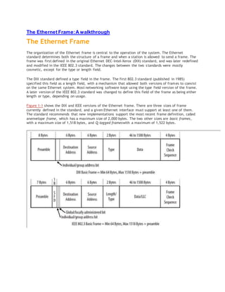
  • 1. The Ethernet Frame:A walkthrough The Ethernet Frame The organization of the Ethernet frame is central to the operation of the system. The Ethernet standard determines both the structure of a frame and when a station is allowed to send a frame. The frame was first defined in the original Ethernet DEC-Intel-Xerox (DIX) standard, and was later redefined and modified in the IEEE 802.3 standard. The changes between the two standards were mostly cosmetic, except for the type or length field. The DIX standard defined a type field in the frame. The first 802.3 standard (published in 1985) specified this field as a length field, with a mechanism that allowed both versions of frames to coexist on the same Ethernet system. Most networking software kept using the type field version of the frame. A later version of the IEEE 802.3 standard was changed to define this field of the frame as being either length or type, depending on usage. Figure 1-1 shows the DIX and IEEE versions of the Ethernet frame. There are three sizes of frame currently defined in the standard, and a given Ethernet interface must support at least one of them. The standard recommends that new implementations support the most recent frame definition, called anenvelope frame, which has a maximum size of 2,000 bytes. The two other sizes are basic frames, with a maximum size of 1,518 bytes, and Q-tagged frameswith a maximum of 1,522 bytes.
  • 2. Figure 1-1. DIX Ethernet and IEEE 802.3 frames Because the DIX and IEEE basic frames both have a maximum size of 1,518 bytes and are identical in terms of the number and length of fields, Ethernet interfaces can send either DIX or IEEE basic frames. The only difference in these frames is in the contents of the fields and the subsequent interpretation of those contents by the network interface software. Now, we’ll take a detailed tour of the frame fields. Preamble The frame begins with the 64-bit preamble field, which was originally incorporated to allow 10 Mb/s Ethernet interfaces to synchronize with the incoming data stream before the fields relevant to carrying the content arrived. The preamble was initially provided to allow for the loss of a few bits due to signal start- up delays as the signal propagates through a cabling system. Like the heat shield of a spacecraft, which protects the spacecraft from burning up during reentry, the preamble was originally developed as a shield to protect the bits in the rest of the frame when operating at 10 Mb/s. The original 10 Mb/s cabling systems could include long stretches of coaxial cables, joined by signal repeaters. The preamble ensures that the entire path has enough time to start up, so that signals are re‐ ceived reliably for the rest of the frame. The higher-speed Ethernet systems use more complex mechanisms for encoding the signals that avoid any signal start-up losses, and these systems don’t need a preamble to protect the frame signals. However, it is maintained for backward compatibility with the original Ethernet frame and to provide
  • 3. some extra timing for interframe house‐ keeping, as demonstrated, for example, in the 40 Gb/s system. While there are differences in how the two standards formally defined the preamble bits, there is no practical difference between the DIX and IEEE preambles. The pattern of bits being sent is identical: DIX standard In the DIX standard, the preamble consists of eight “octets,” or 8-bit bytes. The first seven comprise a sequence of alternating ones and zeros. The eighth byte of the preamble contains 6 bits of alternating ones and zeros, but ends with the special pattern of “1, 1.” These two bits signal to the receiving interface that the end of the preamble has been reached, and that the bits that follow are the actual fields of the frame. IEEE standard In the 802.3 specification, the preamble field is formally divided into two parts consisting of seven bytes of preamble and one byte called the start frame delimit‐ er (SFD). The last two bits of the SFD are 1, 1, as with the DIX standard. Destination Address The destination address field follows the preamble. Each Ethernet interface is assigned a unique 48-bit address, called the interface’s physical or hardware address. The desti‐nation address field contains either the 48-bit Ethernet address that corresponds to the address of the interface in the station that is the destination of the frame, a 48-bit mul‐ ticast address, or the broadcast address. Ethernet interfaces read in every frame up through at least the destination address field. If the destination address does not match the interface’s own Ethernet address, or one of the multicast or broadcast addresses that the interface is programmed to receive, then the interface is free to ignore the rest of the frame. Here is how the two standards implement destination addresses: DIX standard The first bit of the destination address, as sent onto the network medium, is used to distinguish physical addresses from multicast addresses. If the first bit is zero, then the address is the physical address of an interface, which is also known as a unicast address, because a frame sent to this address only goes to one destination. If the first bit of the address is a one, then the frame is being sent to a multicast address. If all 48 bits are ones, this indicates the broadcast, or all-stations, address. IEEE standard The IEEE 802.3 version of the frame adds significance to the second bit of the destination address, which is used to distinguish between locally and globallyad‐ ministered addresses. A globally administered address is a physical address assigned to the interface by the manufacturer, which is indicated by setting the second bit to zero. (DIX Ethernet addresses are always globally administered.) If the address of the Ethernet interface is administered locally for some reason, then the second bit is supposed to be set to a value of one. In the case of a broadcast address, the second bit and all other bits are ones in both the DIX and IEEE standards.
  • 4. Locally administered addresses are rarely used on Ethernet systems, because each Ethernet interfaces is assigned its own unique 48-bit address at the factory. Locally administered addresses, however, were used on some other local area network systems. Understanding physical addresses In Ethernet, the 48-bit physical address is written as 12 hexadecimal digits with the digits paired in groups of two, representing an octet (8 bits) of information. The octet order of transmission on the Ethernet is from the leftmost octet (as written or displayed) to the rightmost octet. The actual transmission order of bits within the octet, however, goes from the least significant bit of the octet through to the most significant bit. This means that an Ethernet address that is written as the hexadecimal string F0-2E-15-6C-77-9B is equivalent to the following sequence of bits, sent over the Ether‐net channel from left to right: 0000 1111 0111 0100 1010 1000 0011 0110 1110 11101101 1001. Therefore, the 48-bit destination address that begins with the hexadecimal value 0xF0 is a unicast address, because the first bit sent on the channel is a zero. Source Address The next field in the frame is the source address. This is the physical address of the device that sent the frame. The source address is not interpreted in any way by the Ethernet MAC protocol, although it must always be the unicast address of the device sending the frame. It is provided for the use of high- level network protocols, and as an aid in troubleshooting. It is also used by switches to build a table associating source addresses with switch ports. An Ethernet station uses its physical address as the source address in any frame it transmits. The DIX standard notes that a station can change the Ethernet source address, while the IEEE standard does not specifically state that an interface may have the ability to override the 48-bit physical address assigned by the manufacturer. However, all Ethernet interfaces in use these days appear to allow the physical address to be changed, which makes it possible for the network administrator or the high-level network software to modify the Ethernet interface address if necessary. To provide the physical address used in the source address field, a vendor of Ethernet equipment acquires an organizationally unique identifier (OUI), which is a unique 24- bit identifier assigned by the IEEE. The OUI forms the first half of the physical address of any Ethernet interface that the vendor manufactures. As each interface is manufac‐ tured, the vendor also assigns a unique address to the interface using the second 24 bits of the 48-bit address space, and that, combined with the OUI, creates the 48-bit address. The OUI may make it possible to identify the vendor of the interface chip, which can sometimes be helpful when troubleshooting network problems. Q-Tag The Q-tag is so called because it carries an 802.1Q tag, also known as a VLAN or priority tag. The 802.1Q standard defines a virtual LAN (VLAN) as one or more switch ports that function as a separate and independent Ethernet system on a switch. Ethernet traffic within a given VLAN (e.g., VLAN 100) will be sent and received only on those ports of the switch that are defined to be members of that particular VLAN (in this case, VLAN 100). A 4-byte-long Q-tag is inserted in an Ethernet frame between the source address and the length/type field to identify the VLAN to which the frame belongs. When a
  • 5. Q- Tag is present, the minimum data field size is reduced to 42 bytes, maintaining a min‐ imum frame size of 64 bytes. Switches can be connected together with an Ethernet segment that functions as a trunk connection that carries Ethernet frames with VLAN tags in them. That, in turn, makes it possible for Ethernet frames belonging to VLAN 100, for example, to be carried be‐ tween multiple switches and sent or received on switch ports that are assigned to VLAN 100. VLAN tagging, a vendor innovation, was originally accomplished using a variety of proprietary approaches. Development of the IEEE 802.1Q standard for virtual bridged LANs produced the VLAN tag as a vendor-neutral mechanism for identifying which VLAN a frame belongs to. The addition of the 4-byte VLAN tag causes the maximum size of an Ethernet frame to be extended from the original maximum of 1,518 bytes (not including the preamble) to a new maximum of 1,522 bytes. Because VLAN tags are only added to Ethernet frames by switches and other devices that have been programmed to send and receive VLAN- tagged frames, this does not affect traditional, or “classic,” Ethernet operation. The first two bytes of the Q-tag contain an Ethernet type identifier of 0x8100. If an Ethernet station that is not programmed to send or receive a VLAN tagged frame hap‐ pens to receive a tagged frame, it will see what looks like a type identifier for an unknown protocol type and simply discard the frame. Envelope Prefix and Suffix As networks grew in complexity and features, the IEEE received requests for more tags to achieve new goals. The VLAN tag provided space for a VLAN ID and Class of Service (CoS) bits, but vendors and standards groups wanted to add extra tags to support new bridging features and other schemes. To accommodate these requests, the 802.3 standards engineers defined an “envelope frame,” which adds an extra 482 bytes to the maximum frame size. The envelope frame was specified in the 802.3as supplement to the standard, adopted in 2006. In another change, the tag data was added to the data field to produce a MAC Client Data field. Because the MAC client data field includes the tagging fields, it may seem like the frame size definition has changed, but in fact this is just a way of referring to the combination of tag data and the data field for the purpose of defining the envelope frame. The 802.3as supplement modified the standard to state that an Ethernet implementation should support at least one of three maximum MAC client data field sizes. The data field size continues to be defined as 46 to 1,500 bytes, but to that is added the tagging infor‐ mation to create the MAC client data field, resulting in the following MAC client data field sizes:  1,500-byte “basic frames” (no tagging information)1,982-byte “envelope frames” (1,500-byte data field plus 482 bytes for all tags)  1,504-byte “Q-tagged frames” (1,500-byte data field plus 4-byte tag) The contents of the tag space are not defined in the Ethernet standard, allowing maxi‐ mum flexibility for the other standards to provide tags in Ethernet frames. Either or both prefix and suffix tags can be used in a given frame, occupying a maximum tag space of 482 bytes if either or both are present. This can result in a maximum frame size of 2,000 bytes. The latest standard simply includes the Q-tag as one of the tags that can be carried in an envelope prefix. The standard notes, “All Q-tagged frames are envelope frames, but not all envelope frames are Q-tagged frames.” In other words, you can use the envelope space for any kind of tagging, and if you
  • 6. use a Q-tag, then it is carried in the envelope prefix as defined in the latest standard. An envelope frame carrying a Q-tag will have a minimum data size of 42 bytes, preserving the minimum frame size of 64 bytes. Tagged frames are typically sent between switch ports that have been configured to add and remove tags as necessary to achieve their goals. Those goals can include VLAN operations and tagging a frame as a member of a given VLAN, or more complex tagging schemes to provide information for use by higher-level switching and routing protocols. Normal stations typically send basic Ethernet frames without tags, and will drop tagged frames that they are not configured to accept. Type or Length Field The old DIX standard and the IEEE standard implement the type and/or length fields differently: DIX standard In the DIX Ethernet standard, this 16-bit field is called a type field, and it always contains an identifier that refers to the type of high-level protocol data being carried in the data field of the Ethernet frame. For example, the hexadecimal value 0x0800 has been assigned as the identifier for the Internet Protocol (IP). A DIX frame being used to carry an IP packet is sent with the value of 0x0800 in the type field of the frame. All IP packets are carried in frames with this value in the type field. IEEE standard When the IEEE 802.3 standard was first published in 1985, the type field was not included, and instead the IEEE specifications called this field a length field. Type fields were added to the IEEE 802.3 standard in 1997, so the use of a type field in the frame is officially recognized in 802.3. This change simply made the common practice of using the type field an official part of the standard. The identifiers used in the type field were originally assigned and maintained by Xerox, but with the type field now part of the IEEE standard, the responsibility for assigning type num‐ bers was transferred to the IEEE. In the IEEE 802.3 standard, this field is called a length/type field, and the hexadecimal value in the field indicates the manner in which the field is being used. The first octet of the field is considered the most significant octet in terms of numeric value. If the value in this field is numerically less than or equal to 1,500 (decimal), then the field is being used as a length field. In that case, the value in the field indicates the number of logical link control (LLC) data octets that follow in the data field of the frame. If the number of LLC octets is less than the minimum required for the data field of the frame, then octets of padding data will automatically be added to make the data field large enough. The content of the padding data is unspecified by the standard. Upon reception of the frame, the length field is used to determine the length of valid data in the data field, and the padding data is discarded. If the value in this field of the frame is numerically greater than or equal to 1,536 decimal (0x600 hex), then the field is being used as a type field.The range of 1,501 to 1,535 was intentionally left undefined in the standard. In that case, the hexadecimal identifier in the field is used to indicate the type of protocol data being carried in the data field of the frame. The network software on the station is responsible for providing any padding data required to ensure that the data field is 46 bytes in length. With this method, there is no conflict or ambiguity about whether the field indicates length or type.
  • 7. Data Field Next comes the data field of the frame, which is also treated differently in the two standards: DIX standard In a DIX frame, this field must contain a minimum of 46 bytes of data, and may range up to a maximum of 1,500 bytes of data. The network protocol software is expected to provide at least 46 bytes of data. IEEE standard The total size of the data field in an IEEE 802.3 frame is the same as in a DIX frame: a minimum of 46 bytes and a maximum of 1,500. However, a logical link control protocol defined in the IEEE 802.2 LLC standard may ride in the data field of the 802.3 frame to provide control information. The LLC protocol is also used as a way to identify the type of protocol data being carried by the frame if the type/length field is used for length information. The LLC protocol data unit (PDU) is carried in the first set of bytes in the data field of the IEEE frame. The structure of the LLC PDU is defined in the IEEE 802.2 LLC standard. The process of figuring out which protocol software stack gets the data in an incoming frame is known as demultiplexing. An Ethernet frame may use the type field to identify the high-level protocol data being carried by the frame. In the LLC specification, the receiving station demultiplexes the frame by deciphering the contents of the logical link control protocol data unit. FCS Field The last field in both the DIX and IEEE frames is the frame check sequence (FCS) field, also called the cyclic redundancy check (CRC). This 32-bit field contains a value that is used to check the integrity of the various bits in the frame fields (not including the preamble/SFD). This value is computed using the CRC, a polynomial that is calculated using the contents of the destination, source, type (or length), and data fields. As the frame is generated by the transmitting station, the CRC value is simultaneously being calculated. The 32 bits of the CRC value that are the result of this calculation are placed in the FCS field as the frame is sent. The x31 coefficient of the CRC polynomial is sent as the first bit of the field, and the x0 coefficient as the last. The CRC is calculated again by the interface in the receiving station as the frame is read in. The result of this second calculation is compared with the value sent in the FCS field by the originating station. If the two values are identical, then the receiving station is provided with a high level of assurance that no errors have occurred during transmission over the Ethernet channel. If the values are not identical, then the interface can discard the frame and increment the frame error counter. End of Frame Detection The presence of a signal on the Ethernet channel is known as carrier. The transmitting interface stops sending data after the last bit of a frame is transmitted, which causes the Ethernet channel to become idle. In the original 10 Mb/s system, the loss of carrier when the channel goes idle signals to the receiving interface that the frame has ended. When the interface detects loss of carrier, it knows that the frame transmission has come to an end. The higher-speed Ethernet systems use more complex signal encoding schemes, which have special symbols available for signaling to the interface the start and end of a frame.
  • 8. A basic frame carrying a maximum data field of 1,500 bytes is actually 1,518 bytes in length (not including the preamble) when the 18 bytes needed for the addresses, length/ type field, and the frame check sequence are included. The addition of a further 482 bytes for envelope frames makes the maximum frame size become 2,000 bytes. This was chosen as a useful maximum frame size that could be handled by a typical Ethernet implementation in an interface or switch port, while providing enough room for current and future prefixes and suffixes.