Inlet
- 1. Inlet
Inlet device in an oil/gas separator is used to direct the flow and absorb the flow momentum of coming stream. However, the inlet has received less attention and “science” than the
gas outlets. Actually inlet device play an important role in overall performance of a separation vessel. The followings are a few traditional or typical inlet device
Contents
1 Traditional inlets
2 Advanced Inlets
2.1 Vance Inlet
2.2 Inlet cyclone
2.3 Cyclone Cluster
2.4 Other Cyclone
3 Selection of Inlet Device
4 References
5 Noteworthy papers in OnePetro
6 External links
7 See also
8 Category
Traditional inlets
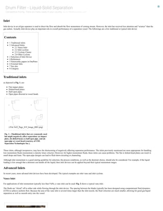
as depicted in Fig. 1, are:
Flat impact plates
Dishedhead plates
Halfopen pipes
Open pipes directed at vessel heads
(/File:Vol3_Page_019_Image_0001.png)
Fig. 1—Thaditional inlets that are commonly used
but might negatively affect separation: (a) impact
plate, (b) dished head, (c) halfopen pipe, and (d)
open pipe at vessel head (courtesy of CDS
Separation Technologies Inc.).
These inlets, although inexpensive, may have the shortcoming of negatively affecting separation performance. The inlets previously mentioned are more appropriate for handling
lowmomentum fluids (momentum is density times velocity). However, for highermomentum fluids, these inlets can cause problems. The flat or dishedhead plates can result in
small drops and foam. The openpipe designs can lead to fluid shortcircuiting or channeling.
Although inlet momentum is a good starting guideline for selection, the process conditions, as well as the demister choice, should also be considered. For example, if the liquid
loading is low enough that a demister can handle all the liquid, then inlet devices can be applied beyond their typical momentum ranges.
Advanced Inlets
In recent years, more advaned inlet devices have been developed. The typical examples are inlet vane and inlet cyclone.
Vance Inlet
For applications of inlet momentum typically less than 9 kPa, a vane inlet can be used. Fig. 2 shows a typical vane inlet.
The fluids are “sliced” off to either side while flowing through the inlet device. The spacing between the blades typically has been designed using computational fluid dynamics
(CFD) to achieve uniform flow. Because the area of the vane inlet is several times larger than the inlet nozzle, the fluid velocities are much smaller, allowing for good gas/liquid
separation as well as smooth entry into the vessel.
Drum Filter - Liquid-Solid Separation
Competitive Pricing .There are many cases in your country. Go to 艮ltrationchina.com
- 2. (/File:Vol3_Page_023_Image_0001.png)
Fig. 2—Vanetype inlet device in which incoming
fluids are “sliced” off to the sides (courtesy of
CDS Separation Technologies Inc.).
For application of foaming streams, the inlet cyclone are now becoming more widely used. See Figs. 2.5a , 2.5b , and 2.6 for typical examples. The advantages of a cyclonic or
vortex inlet are:
High allowable inlet momentums
Defoaming characteristics
Liquid/liquid coalescing benefits
Gas demisting benefits
High liquid levels
Inlet cyclone
The inlet cyclone can be used for inlet momentums factor of 10 higher than pipe inlets. Typically, pipe inlets are used for momentums (ρV2, where ρ is bulk density, kg/m3, and V is
bulk velocity, m/s) less than 1,000 Pa. Inlet cyclones have been used successfully to 65,000 Pa. Although ρV2 is energy, it is referred to as (transport of) momentum.
Because of the centrifugal flow, large foam bubbles are broken, liquid drops are removed from the gas phase, and liquid/liquid coalescence occurs within the cyclone. A problem with
some cyclones is that a poorly designed liquid outlet can shear the liquids, offsetting the benefits of the coalescence and possibly making the situation worse. For cases in which a
high liquid level is required in the separator, the inlet cyclone can be submerged up to the gas outlet level. Moreover, the cylone inlet allows the use of a shorter retention time due to
the rapid degass process, in which large bubble foam is minimized or eliminated. Without the cyclonic inlet, foam can occupy a considerable volume in the separator. The use of a
cyclonic inlet often allows foam to be ignored as a sizing consideration. Thus, for highcapacity crudeoil separators (which are the ones most limited by foam), the cyclone inlet can
significantly reduce the required vessel liquid and foam holdup volume, size, weight, and cost.
Fig. 3 shows two different types of inlet cyclones. One cyclone has a simple tangential inlet with or without a gas vortex finder. In cyclones without a vortex finder, gas can escape
quickly out the top. This has two effects: the loss of gas yields a lower centrifugal acceleration within the cyclone, and as the gas leaves the top, it carries liquid with it as well as
shearing the liquid. More mist is generated, which may impact the downstream demister. With a tangential inlet, the fluids may also circle back on the inlet, disrupting the incoming
flow. The bottom of the cyclone is submerged below a liquid level to prevent gas from blowing out the bottom (blowby). A simple flat plate baffle beneath the liquid outlet spreads
the flow out radially.
(/File:Vol3_Page_022_Image_0001.png)
Fig. 3—Examples of inlet cyclones (courtesy of
CDS Separation Technologies Inc.).
Cyclone Cluster
As the thoughput increase, a cyclone cluster shown in Fig. 4 may be considered to increase vessel capacity. In Fig. 4a, fluids enter the cyclones from a top shell side inlet nozzle and
are split to the different cyclones. In Fig. 4b, incoming process fluids are accelerated in the manifold to a desired velocity. Each tube peels off a portion of that stream, which enters
the tube tangentially, generating rotational flow. In both cases, within each tube, the swirling fluids create a high force for separation of gas/liquid. The gas accumulates in the center,
forming a gas core, exits through an orifice in the top of the tube, and flows into the separator gas phase. Liquids are slung to the tube wall, where they migrate downward as a
continuous sheet. They exit the tube through a peripheral gap in the tube wall at the bottom and flow out into the separator liquid bath, in which the bottoms of the tubes are
submerged.
- 3. (/File:Vol3_Page_020_Image_0001.png)
Fig. 3a—Cyclone/vortex tube cluster:
top (shell side) entry (courtesy of CDS
Separation Technologies Inc.).
(/File:Vol3_Page_021_Image_0001.png)
Fig. 3b—Cyclone/vortex tube cluster:
side (head) entry (courtesy of Natco).
Other Cyclone
The other cyclone has stationary turbine blades used to provide spin. This has the advantage of lowering the shear on the fluids. Lower shear results in less mist generation and
droplet shearing. In the liquid section, the liquid outlet with proprietary internals is designed to prevent gas from escaping. The bottom of the cyclone also provides some
backpressure through low shear channel flow or a perforated cylinder. This additional backpressure allows the cyclone to operate at higher gas capacities than the first cyclone and,
hence, with higher centrifugal accelerations. A bottom flat plate, in conjunction with the perforated cylinder, spreads the liquid flow out more uniformly.
Selection of Inlet Device
The cyclonictype inlet device is good to diffuse the momentum of the incoming feed stream and allows for the removal of any bulk liquids and solids that may be present. The
cyclonic inlet device is designed such that it can operate at both high and low gas/oil ratios without the possibility of gas blowby and excessive liquid reentrainment into the gas
phase.
The main characteristics to look for in an inlet cyclone are listed next.
High liquid drainage capacity: This is necessary to prevent internal “choking” of the cyclone. In this case, the liquid carryover into the gas phase will be excessive, which could
cause too high a liquid load on the downstream devices. Also, there would be considerable disruption to the internal flow field, which means the cyclone will not operate
correctly.
Low reentrainment of liquid into the gas phase: This means that the downstream mist eliminating devices will not be overloaded. Also, the mist eliminating section will be
working optimally; therefore, the best separation performance from the separator can be realized.
Liquid reentrainment: The main cause of liquid reentrainment within the gas phase is “creep” that is caused by internal pressure differences causing liquid to move along
internal surfaces. Within the cyclone, the effect of creep can be minimized by use of rings located around the gas vortex finder.
Low shear forces on the reentrained liquids in the gas: Low shear forces are beneficial, given that the droplet distribution of the reentrained liquids leaving the cyclone is not
too fine. The finer the droplets, the more difficult it becomes for the downstream mist eliminating section to remove them—hence, the overall liquid carryover from the
separator increases.
Low shear forces on the dispersed phase within the liquid outlet: Low shear forces are beneficial in that the droplet distribution of the dispersed phase liquid leaving the
cyclone is not too small and does not form an emulsion. As the droplets get finer, it becomes more difficult for the downstream gravity settling devices to coalesce and remove
them; hence, more is carried over in the exiting streams. This can be accomplished by ensuring that the liquid flow channels within the cyclone are relatively large and that any
perforated holes are of the correct size to minimize shear.
Minimum gas blowby to the liquid outlet: Gas blowby is seen when gas exits with the liquid phase from the bottom of the cyclone. If the amount of gas is considerable, a
bubbling mass of liquid/gas is formed, which has a negative effect because of foam generation and mixing.
Care must be taken when designing inlet cyclones for separators. Cyclones are designed on the basis of a pressure balance between the pressure drop needed to force the gas up and
out the top of the cyclone and that required to push the liquid out the bottom of the cyclone. If the gas pressure drop is higher than the liquid pressure drop, the liquid level inside the
cyclone will be lower than that of the level of the surrounding liquid in the separator and vice versa. Flow rate turndown and changes in producing gastooil ratio (GOR) then play
important roles in the determination of the operating range of the cyclones. For example, cyclones may be properly designed for, say, 50,000 B/D of liquids at 1,000 GOR. However,
if the GOR is actually 1,500, gas may blow out the bottom of the cyclones and create foam throughout the separator.
References
Use this section for citation of items referenced in the text to show your sources. [The sources should be available to the reader, i.e., not an internal company document.]
Noteworthy papers in OnePetro
Song, J.H., Jeong, B.E., Kim, H.J. and Gil, S.S. ThreePhases Separator Sizing Using Drop Size Distribution. OTC20558MS presented at the Offshore Technology Conference,
Houston, Texas, USA, 36 May. http://dx.doi.org/10.4043/20558MS (http://dx.doi.org/10.4043/20558MS).
External links
Use this section to provide links to relevant material on websites other than PetroWiki and OnePetro
See also
Oil and gas separators (/Oil_and_gas_separators)
PEH:Oil_and_Gas_Separators (/PEH:Oil_and_Gas_Separators)
Category
Categories (/Special:Categories): 4.1.2 Separation and treating (/Category:4.1.2_Separation_and_treating) NR (/Category:NR)