
Recommended
More Related Content
What's hot
What's hot (15)
Similar to Ll rbt rag ppt 2020
Similar to Ll rbt rag ppt 2020 (20)
Recently uploaded
Recently uploaded (20)
Ll rbt rag ppt 2020
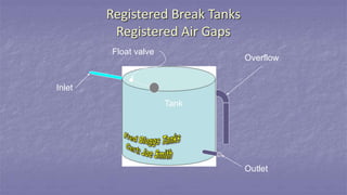
- 1. Registered Break Tanks Registered Air Gaps Inlet Outlet Overflow Tank Float valve
- 2. Type “A” - unobstructed air gap Registered Break Tank types
- 3. Type “B” – air gap with overflow Registered Break Tank types
- 4. Type “C” – air gap with diverter and overflow Registered Break Tank types
- 5. Type “D” – air gap with injector NOT CURRENT Registered Break Tank types
- 6. Type “E” - hygienic air gap Registered Break Tank types
- 7. Registered Break Tank design procedure Work out inlet pressure in kPa Determine orifice size in mm (not just the valve size) Use appropriate table to select the appropriate incoming flow in L/sec Table 8.4.4.1 – AS3500.1 : 2018 or Table A1 – AS2845.2 : 2010 Determine the design of the overflow outlet Figure 8.4.4.1(A, B or C) – AS3500.1 : 2018 or Figure A1, A2 or A3 – AS2845.2 : 2010 Choose from the table a combination of spill level distances and overflow sizes that meet the requirements of the specific tank location.
- 8. Registered Break Tank design procedure Continued Note the chosen spill level distance in mm. Determine whether the inlet discharge point is affected by near wall Use appropriate table to select the appropriate air gap in mm. Table 4.6.3.2 – AS3500.1 : 2018 or Table A3 – AS2845.2 : 2010 Add the air gap measurement and the spill level distance together to provide you with the minimum distance between the discharge point of the inlet float/servo valve and the invert or weir of the overflow pipe
- 9. Registered Break Tank design procedure
- 10. Air Gap Requirements For a Registered break tank to be considered as a backflow prevention device for high hazards, it must maintain an air gap AT ALL TIMES.
- 11. Air Gap Requirements The position of the inlet valve discharge point in relation to the invert of the overflow pipe will dictate if the air gap requirements are being met. There are a number of factors that will affect the above positions; 1. Inlet pressure to the tank in kPa 2. Orifice size on the float /servo valve in mm 3. Flow rate into tank in L/sec 4. Design and location of overflow outlet 5. Size of overflow outlet in mm 6. Spill level in mm 7. Position of inlet discharge point 8. Air gap in mm
- 12. Key terms for RBT calculations
- 13. INLET ORIFICE
- 14. The Near Wall Air gap is affected when the distance from the tank wall to the control valve outlet is less than 3 times the effective opening – single wall.
- 15. The Near Wall 4 times the effective opening Float valve Effective opening 4 times the effective opening from two intersecting tank walls Air gap is affected when the distance from the tank wall to the control valve outlet is less than 4 times the effective opening – intersecting wall.
- 16. Let’s have a go! Sizing exercises
- 18. Table A3 – AS2845.2 : 2010 & Table 4.6.3.2 – AS3500.1 : 2018
- 19. 2020mm mm
- 20. Table A3 – AS2845.2 : 2010 & Table 4.6.3.2 – AS3500.1 : 2018
- 21. 20 mm 40 mm 40 mm 75 mm 80 mm 150 mm 25 mm 25 mm 55 mm 50 mm
- 23. Table A1 – AS2845.2 : 2010 & Table 8.4.4.1 – AS3500.1 : 2018
- 24. .3 L/sec9.3L/sec
- 25. Fig A1 – AS2845.2 : 2010 & Fig 8.4.4.1(A) – AS3500.1 : 2018
- 27. Table A3 – AS2845.2 : 2010 & Table 4.6.3.2 – AS3500.1 : 2018
- 29. Table A1 – AS2845.2 : 2010 & Table 8.4.4.1 – AS3500.1 : 2018
- 31. Fig A2 – AS2845.2 : 2010 & Fig 8.4.4.1(B) – AS3500.1 : 2018
- 32. 9.3 L/sec 125 mm 150 mm 50 mm 1.49 L/sec 9.3L/sec 125mm 150mm 50mm 1.49L/sec 40mm, 50mm & 75mm 200mm, 100mm & 30mm
- 33. A3 – AS2845.2 : 2010 4.6.3.2 – AS3500.1 : 2018
- 34. 9.3L/sec 125mm 150mm 50mm 1.49L/sec 40mm, 50mm & 75mm 200mm, 100mm & 30mm 40mm
- 35. Consolidated calculation data Calc 1 Calc 2 Calc 3
- 36. Tank calc example 1 Calc data 40mm Minimum allowable?
- 37. Tank calc example 2 Calc data 10mm inlet orifice 40mm Fred Bloggs Tanks Cert:Joe Smith (Joe’s Plumbing)
- 38. Tank calc example 3 Calc data 32mm float valve 150mm ? ? Fred Bloggs Tanks Cert:Joe Smith (Joe’s Plumbing)
- 39. RAG Test procedure a) Measure and record the distance from the spill level to the outlet of the water service b) Check the air gap complies with Table A3 (Minimum air gap), Appendix A of AS2845.2
- 40. RBT Test procedure a) Check that the break tank has an overflow fitted below the level of the inlet b) Inspect overflow for any obstructions c) Check that there is no bridging device between the outlet and the water in the tank d) Record the size of the inlet orifice and calculate cross-sectional area for the overflow e) Measure and record the height (h) of water above the invert of the overflow, in millimetres. Height (h) shall comply with the requirements of AS2845.2