
Recommended
More Related Content
What's hot
What's hot (20)
Similar to Ultrasonic testing 1766001
Similar to Ultrasonic testing 1766001 (20)
Recently uploaded
Recently uploaded (20)
Ultrasonic testing 1766001
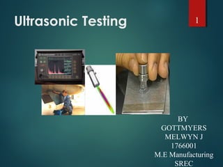
- 1. Ultrasonic Testing BY GOTTMYERS MELWYN J 1766001 M.E Manufacturing SREC 1
- 2. Introduction This module presents an introduction to the NDT method of ultrasonic testing. Ultrasonic testing uses high frequency sound energy to conduct examinations and make measurements. Ultrasonic examinations can be conducted on a wide variety of material forms including castings, forgings, welds, and composites. A considerable amount of information about the part being examined can be collected, such as the presence of discontinuities, part or coating thickness; and acoustical properties can often be correlated to certain properties of the material. 2
- 3. Basic Principles of Sound Sound is produced by a vibrating body and travels in the form of a wave. Sound waves travel through materials by vibrating the particles that make up the material. The pitch of the sound is determined by the frequency of the wave (vibrations or cycles completed in a certain period of time). Ultrasound is sound with a pitch too high to be detected by the human ear. 3
- 4. Basic Principles of Sound (cont.) The measurement of sound waves from crest to crest determines its wavelength (λ). The time is takes a sound wave to travel a distance of one complete wavelength is the same amount of time it takes the source to execute one complete vibration. The sound wavelength is inversely proportional to its frequency. (λ = 1/f) Several wave modes of vibration are used in ultrasonic inspection. The most common are longitudinal, shear, and Rayleigh (surface) waves. 4
- 5. Ultrasound Generation The transducer is capable of both transmitting and receiving sound energy. Ultrasound is generated with a transducer. A piezoelectric element in the transducer converts electrical energy into mechanical vibrations (sound), and vice versa. 5
- 6. Principles of Ultrasonic Inspection Ultrasonic waves are introduced into a material where they travel in a straight line and at a constant speed until they encounter a surface. At surface interfaces some of the wave energy is reflected and some is transmitted. The amount of reflected or transmitted energy can be detected and provides information about the size of the reflector. The travel time of the sound can be measured and this provides information on the distance that the sound has traveled. 6
- 7. Test Techniques Ultrasonic testing is a very versatile inspection method, and inspections can be accomplished in a number of different ways. Ultrasonic inspection techniques are commonly divided into three primary classifications. Pulse-echo and Through Transmission (Relates to whether reflected or transmitted energy is used) Normal Beam and Angle Beam (Relates to the angle that the sound energy enters the test article) Contact and Immersion (Relates to the method of coupling the transducer to the test article) 7
- 8. • In pulse-echo testing, a transducer sends out a pulse of energy and the same or a second transducer listens for reflected energy (an echo). • Reflections occur due to the presence of discontinuities and the surfaces of the test article. • The amount of reflected sound energy is displayed versus time, which provides the inspector information about the size and the location of features that reflect the sound. f Test Techniques - Pulse-Echo plate crack 0 2 4 6 8 10 initial pulse crack echo back surface echo UT Instrument Screen 8
- 9. Test Techniques – Pulse-Echo (cont.) Digital display showing signal generated from sound reflecting off back surface. Digital display showing the presence of a reflector midway through material, with lower amplitude back surface reflector. The pulse-echo technique allows testing when access to only one side of the material is possible, and it allows the location of reflectors to be precisely determined. 9
- 10. Test Techniques – Through-Transmission 0 2 4 6 8 10 2 11 • Two transducers located on opposing sides of the test specimen are used. One transducer acts as a transmitter, the other as a receiver. • Discontinuities in the sound path will result in a partial or total loss of sound being transmitted and be indicated by a decrease in the received signal amplitude. • Through transmission is useful in detecting discontinuities that are not good reflectors, and when signal strength is weak. It does not provide depth information. T R T R 11 2 10
- 11. Digital display showing received sound through material thickness. Digital display showing loss of received signal due to presence of a discontinuity in the sound field. Test Techniques – Through-Transmission11
- 12. Test Techniques – Normal and Angle Beam • In normal beam testing, the sound beam is introduced into the test article at 90 degree to the surface. • In angle beam testing, the sound beam is introduced into the test article at some angle other than 90. • The choice between normal and angle beam inspection usually depends on two considerations: - The orientation of the feature of interest – the sound should be directed to produce the largest reflection from the feature. - Obstructions on the surface of the part that must be worked around. 12
- 13. 0 2 4 6 8 10 FWE BWE DE 2IP IP = Initial Pulse FWE = Front Wall Echo DE = Defect Echo BWE = Back Wall Echo 0 2 4 6 8 10 FWE BWE 1IP1 2 Defect Test Techniques – Contact Vs Immersion • To get useful levels of sound energy into a material, the air between the transducer and the test article must be removed. This is referred to as coupling. • In contact testing (shown on the previous slides) a couplant such as water, oil or a gel is applied between the transducer and the part. • In immersion testing, the part and the transducer are place in a water bath. This arrangement allows better movement of the transducer while maintaining consistent coupling. • With immersion testing, an echo from the front surface of the part is seen in the signal but otherwise signal interpretation is the same for the two techniques. 13
- 14. Inspection Applications Some of the applications for which ultrasonic testing may be employed include: • Flaw detection (cracks, inclusions, porosity, etc.) • Erosion & corrosion thickness gauging • Assessment of bond integrity in adhesively joined and brazed components • Estimation of void content in composites and plastics • Measurement of case hardening depth in steels • Estimation of grain size in metals On the following slides are examples of some common applications of ultrasonic inspection. 14
- 15. Thickness Gauging Ultrasonic thickness gauging is routinely utilized in the petrochemical and utility industries to determine various degrees of corrosion/erosion. • Applications include piping systems, storage and containment facilities, and pressure vessels. 15
- 16. Flaw Detection - Delaminations Signal showing multiple back surface echoes in an unflawed area. Additional echoes indicate delaminations in the member. Contact, pulse-echo inspection for delaminations on 36” rolled beam. 16
- 17. Flaw Detection in Welds One of the most widely used methods of inspecting weldments is ultrasonic inspection. Full penetration groove welds lend themselves readily to angle beam shear wave examination. 17
- 18. Equipment Equipment for ultrasonic testing is very diversified. Proper selection is important to insure accurate inspection data as desired for specific applications. In general, there are three basic components that comprise an ultrasonic test system: - Instrumentation - Transducers - Calibration Standards 18
- 19. Transducers • Transducers are manufactured in a variety of forms, shapes and sizes for varying applications. • Transducers are categorized in a number of ways which include: - Contact or immersion - Single or dual element - Normal or angle beam • In selecting a transducer for a given application, it is important to choose the desired frequency, bandwidth, size, and in some cases focusing which optimizes the inspection capabilities. 19
- 20. Contact Transducers Contact transducers are designed to withstand rigorous use, and usually have a wear plate on the bottom surface to protect the piezoelectric element from contact with the surface of the test article. Many incorporate ergonomic designs for ease of grip while scanning along the surface. 20
- 21. Contact Transducers (cont.) A way to improve near surface resolution with a single element transducer is through the use of a delay line. Delay line transducers have a plastic piece that is a sound path that provides a time delay between the sound generation and reception of reflected energy. Interchangeable pieces make it possible to configure the transducer with insulating wear caps or flexible membranes that conform to rough surfaces. Common applications include thickness gauging and high temperature measurements. 21
- 22. Calibration Standards Calibration is a operation of configuring the ultrasonic test equipment to known values. This provides the inspector with a means of comparing test signals to known measurements. Calibration standards come in a wide variety of material types, and configurations due to the diversity of inspection applications. Calibration standards are typically manufactured from materials of the same acoustic properties as those of the test articles. The following slides provide examples of specific types of standards. 22
- 23. Calibration Standards (cont.) Thickness calibration standards may be flat or curved for pipe and tubing applications, consisting of simple variations in material thickness. Distance/Area Amplitude standards utilize flat bottom holes or side drilled holes to establish known reflector size with changes in sound path form the entry surface. ASTM Distance/Area Amplitude NAVSHIPS 23
- 24. Calibration Standards (cont.) There are also calibration standards for use in angle beam inspections when flaws are not parallel to entry surface. These standards utilized side drilled holes, notches, and geometric configuration to establish time distance and amplitude relationships. IIW DSC DC Rhompas SC ASME Pipe Sec. XI 24
- 25. Data Presentation Information from ultrasonic testing can be presented in a number of differing formats. Three of the more common formats include: A-scan B-scan C-scan These three formats will be discussed in the next few slides. 25
- 26. Data Presentation - A-scan A-scan presentation displays the amount of received ultrasonic energy as a function of time. Relative discontinuity size can be estimated by comparing the signal amplitude to that from a known reflector. Reflector depth can be determined by the position of the signal on the horizontal sweep. Time SignalAmplitudeSignalAmplitude Time 26
- 27. Data Presentation - B-scan B-scan presentations display a profile view (cross-sectional) of a test specimen. Only the reflector depth in the cross-section and the linear dimensions can be determined. A limitation to this display technique is that reflectors may be masked by larger reflectors near the surface. 27
- 28. Data Presentation - C-scan The C-scan presentation displays a plan type view of the test specimen and discontinuities. C-scan presentations are produced with an automated data acquisition system, such as in immersion scanning. Use of A-scan in conjunction with C-scan is necessary when depth determination is desired. Photo of a Composite Component C-Scan Image of Internal Features 28
- 29. Advantage of Ultrasonic Testing Sensitive to both surface and subsurface discontinuities. Depth of penetration for flaw detection or measurement is superior to other methods. Only single-sided access is needed when pulse-echo technique is used. High accuracy in determining reflector position and estimating size and shape. Minimal part preparation required. Electronic equipment provides instantaneous results. Detailed images can be produced with automated systems. Has other uses such as thickness measurements, in addition to flaw detection. 29
- 30. Limitations of Ultrasonic Testing Surface must be accessible to transmit ultrasound. Skill and training is more extensive than with some other methods. Normally requires a coupling medium to promote transfer of sound energy into test specimen. Materials that are rough, irregular in shape, very small, exceptionally thin or not homogeneous are difficult to inspect. Cast iron and other coarse grained materials are difficult to inspect due to low sound transmission and high signal noise. Linear defects oriented parallel to the sound beam may go undetected. Reference standards are required for both equipment calibration, and characterization of flaws. 30
- 31. THANK YOU 31
Editor's Notes
- This presentation was developed to provide students in industrial technology programs, such as welding, an introduction to ultrasonic testing. The material by itself is not intended to train individuals to perform NDT functions but rather to acquaint individuals with the NDT equipment and methods that they are likely to encounter in industry. More information has been included than might necessarily be required for a general introduction to the subject as some instructors have requested at least 60 minutes of material. Instructors can modify the presentation to meet their needs by simply hiding slides in the “slide sorter” view of PowerPoint.” This presentation is one of eight developed by the Collaboration for NDT Education. The topics covered by the other presentations are: Introduction to Nondestructive Testing Visual Inspection Penetrant Testing Magnetic Particle Testing Radiographic Testing Eddy Current Testing Welder Certification All rights are reserved by the authors and the presentation cannot be copied or distributed except by the Collaboration for NDT Education. A free copy of the presentations can be requested by contacting the Collaboration at NDT-ed@cnde.iastate.edu.