This document presents a comparative analysis of three types of controllers (backstepping, sliding mode, and PID) designed to control a PWM voltage inverter used in standalone photovoltaic microgrids. The backstepping controller demonstrated superior performance in generating a sinusoidal voltage output across varying load conditions, compared to the other methods. The study utilized simulations in MATLAB/Simulink to validate the effectiveness of the control strategies.
![International Journal of Electrical and Computer Engineering (IJECE)
Vol. 12, No. 1, February 2022, pp. 166~178
ISSN: 2088-8708, DOI: 10.11591/ijece.v12i1.pp166-178 166
Journal homepage: http://ijece.iaescore.com
Comparison of backstepping, sliding mode and PID regulators
for a voltage inverter
Radouane Majdoul1
, Abelwahed Touati1
, Abderrahmane Ouchatti2
,
Abderrahim Taouni2
, Elhassane Abdelmounim3
1
Laboratory of Complex Cyber Physical Systems in ENSAM, Hassan 2nd
University Casablanca, Casablanca, Morocco
2
Laboratory of Electrical Systems and Control Engineering at Aïn Chock Science Faculty,
Hassan 2nd
University Casablanca, Casablanca, Morocco
3
Laboratory of System Analysis and Information Technology in Science and Technical Faculty,
Hassan 1st
University Settat, Settat, Morocco
Article Info ABSTRACT
Article history:
Received Feb 2, 2021
Revised Jul 20, 2021
Accepted Aug 5, 2021
In the present paper, an efficient and performant nonlinear regulator is
designed for the control of the pulse width modulation (PWM) voltage
inverter that can be used in a standalone photovoltaic microgrid. The main
objective of our control is to produce a sinusoidal voltage output signal with
amplitude and frequency that are fixed by the reference signal for different
loads including linear or nonlinear types. A comparative performance study
of controllers based on linear and non-linear techniques such as
backstepping, sliding mode, and proportional integral derivative (PID) is
developed to ensure the best choice among these three types of controllers.
The performance of the system is investigated and compared under various
operating conditions by simulations in the MATLAB/Simulink environment
to demonstrate the effectiveness of the control methods. Our investigation
shows that the backstepping controller can give better performance than the
sliding mode and PID controllers. The accuracy and efficiency of the
proposed backstepping controller are verified experimentally in terms of
tracking objectives.
Keywords:
Averaging model
Backstepping
DC-AC converter
Lyapunov
Nonlinear control
Sliding mode
Voltage inverter
This is an open access article under the CC BY-SA license.
Corresponding Author:
Radouane Majdoul
Laboratory of Complex Cyber Physical Systems, ENSAM, Hassan 2nd
University of Casablanca
150, Nil Street, Sidi Othmane Casablanca, Morocco
Email: Radouane.majdoul@univh2c.ma
1. INTRODUCTION
In the literature, a multitude of types of controllers is developed and used to control the static power
converters used in several electric systems (stand-alone or grid-connected photovoltaic systems, variable
frequency drive, UPS…). Nowadays, system control is one of the richest domains in terms of algorithms,
analysis tools, and design techniques. For a large class of non-linear systems, linear analysis methods
generally give acceptable results. Classical linear methods are still used by many researchers [1]-[4] and
others have designed their control strategy based on simple proportional integral (PI) or proportional resonant
(PR) controllers [5], [6]. In some cases, approximate methods (the harmonic equivalent or Lyapunov's first
method) are used to overcome the limitations of linear methods. Unfortunately for a large majority of
systems, these two approaches remain insufficient and only provide the necessary conditions of stability. In
other laboratories, researchers have shown interest in control strategies using the concept of platitude of
differential systems [7]. This last technique allows state trajectories to be controlled even during a steady
state. This property is not always ensured with PI controllers or other linear controllers. In other advanced](https://image.slidesharecdn.com/1824510emr20jul2febl-211206060822/75/Comparison-of-backstepping-sliding-mode-and-PID-regulators-for-a-voltage-inverter-1-2048.jpg)
![Int J Elec & Comp Eng ISSN: 2088-8708
Comparison of backstepping, sliding mode and PID regulators … (Radouane Majdoul)
167
control research works, we find interesting studies of comparative performance between different types of
approaches: proportional integral derivative (PID) and fuzzy logic controllers or between sliding mode and
platitude controllers [8], [9].
One of the most interesting approaches in recent years in the control and command of systems is the
one based on Lyapunov's theory (second method) which presents a better alternative to linear methods [10].
The main idea of the use of the Lyapunov function (in adaptive control) is to compute a control law (and
possibly a parameter updating law) to ensure that the derivative of a certain well-chosen positive defined
function is non-positive. In his research, Houari [7] explored the platitude control strategy for the control of
autonomous PV systems; this technique produces good results as a low response time of the order of 6ms and
a low total harmonic distortion (THD). A comparative analysis with a conventional type control (PID) and an
advanced control using input-output linearization was proposed and justified the interest of the platitude
control technique. More advanced methods based on Lyapunov theory such as backstepping, sliding mode, or
passivity are still little used. In this paper, we propose the implementation of a single-phase voltage inverter
used in a stand-alone photovoltaic system and controlled by a high-performance nonlinear controller. To
ensure the best choice between three types of controllers, we establish a performance comparison between
two non-linear controllers based on the Lyapunov function, namely the backstepping and the sliding mode
controllers. This comparison also includes the performance of the system driven by the commonly used linear
PID controller. These three controllers will be tested first in the presence of a sudden variation of the
reference and then during a strong disturbance and large variation of the load. We make a comparison
between the aforementioned controllers to justify the advantages and disadvantages of each one.
The remainder of this article is organized as follows: In section 2, a summary description is made of
the pulse width modulation (PWM) inverter with an output LC filter. An equivalent mathematical model is
presented using the theory of averaging values. Section 3 presents the development of three regulators types
for this DC-AC converter system. The backstepping technique is developed first and, the sliding mode
approach is the second case. Finally, we synthesized a PID controller to complete the comparison. The three
controllers are tested, simulated, and implemented in the fourth section with comments and conclusions.
2. MODELLING OF THE PWM VOLTAGE INVERTER AND THE LC OUTPUT FILTER
2.1. Mathematical model of the PWM inverter associated with the LC filter
The mathematical equations that govern the circuit in Figure 1 are noted in (1), (2):
𝐿
𝑑𝑖𝐿
𝑑𝑡
= 𝑣𝐴𝐵 − 𝑣𝑆 − 𝑟. 𝑖𝐿 (1)
𝐶
𝑑𝑣𝑆
𝑑𝑡
= 𝑖𝐿 − 𝑖𝑆 (2)
The output voltage vAB of the converter takes two bipolar levels according to the control signal μ and then to
the state of the 4 power switches:
𝑣𝐴𝐵 = {
𝑉𝐷𝐶 𝑤ℎ𝑒𝑛 𝑜𝑛𝑙𝑦 (𝐾1, 𝐾′2) 𝑎𝑟𝑒 𝑂𝑁 𝑖𝑒 µ = 1
−𝑉𝐷𝐶 𝑤ℎ𝑒𝑛 𝑜𝑛𝑙𝑦 (𝐾2, 𝐾′
1) 𝑎𝑟𝑒 𝑂𝑁 𝑖𝑒 µ = −1
𝑣𝐴𝐵 = µ. 𝑉𝐷𝐶 (3)
We deduce the voltage expression vAB and subsequently the commuted model of the system.
𝐿
𝑑𝑖𝐿
𝑑𝑡
= µ. 𝑉𝐷𝐶 − 𝑣𝑆 − 𝑟. 𝑖𝐿 (4)
𝐶
𝑑𝑣𝑆
𝑑𝑡
= 𝑖𝐿 − 𝑖𝑆 (5)
Our DC-AC converter is a variable structure system. The signal 𝑣𝐴𝐵 is not a continuous electrical
quantity and takes two voltage levels VDC or - VDC so is unsuited for designing a continuous control law. The
average model is widely used for modeling static converters [11], [12]; it assumes that the switching period is
very small compared to the system dynamics. In our case, this is largely justified. Thus, the average model
result of the inverter system is as (6), (7):
𝐶 𝑥̇1 = 𝑥2 − 𝑖𝑆 (6)](https://image.slidesharecdn.com/1824510emr20jul2febl-211206060822/75/Comparison-of-backstepping-sliding-mode-and-PID-regulators-for-a-voltage-inverter-2-2048.jpg)
![ ISSN: 2088-8708
Int J Elec & Comp Eng, Vol. 12, No. 1, February 2022: 166-178
168
𝐿 𝑥̇2 = 𝑢. 𝑉𝐷𝐶 − 𝑥1 − 𝑟. 𝑥2 (7)
where x1 𝑎𝑛𝑑 x2 respectively denote the average values over the switching period of vS the voltage across the
capacitor C and iL the current flowing in the inductor L. The control system input u takes continuous values
between -1 and 1 and represents the mean value of the PWM control signal μ. The electrical quantities x1 and
x2 are accessible and measurable.
Figure 1. The single-phase PWM inverter associated with the output LC filter
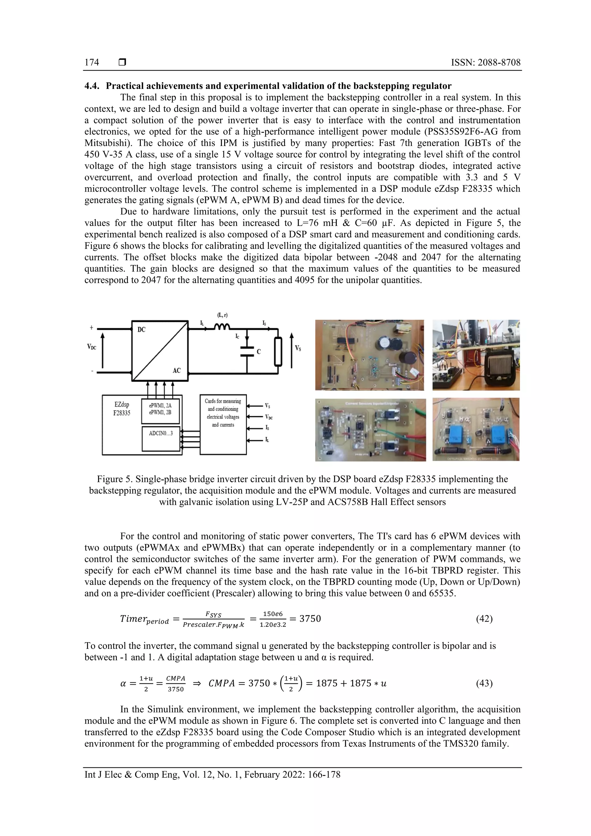
3. CONTROLLERS DESIGN
Our objective is to design three controllers that allow the inverter to produce a pure sine wave
voltage with a fixed amplitude and frequency regardless of the load. The output voltage must track a desired
reference signal:
𝑥1
𝑑(𝑡) = 𝑉√2 sin (𝜔𝑡)
V=230 V and ω=2π50 represent respectively, the RMS and the frequency of the sinusoidal reference signal.
3.1. Design of backstepping controller
In control theory, the backstepping approach has been developed to design stabilized controls for
nonlinear dynamic systems [13], [14]. In this approach, control systems are designed and developed from
basic subsystems radiating from an unreducible one that can be stabilized using other techniques. Due to the
recursive design structure, the developer is able to begin the design process at the known-stable system and
back out new controls that gradually stabilize each outer subsystem. The process ends after many steps when
the final outer control is achieved. Therefore, this process is commonly known as "backstepping control"
[15]-[19].
Step 1: Design of the inner loop
Consider the tracking error z1 defined by (8):
𝑧1 = 𝐶 ( 𝑥1 − 𝑥1
𝑑
) (8)
Its dynamics is given by (9), (10):
𝑧̇1 = 𝐶 ( 𝑥̇1 − 𝑥̇1
𝑑
) (9)
𝑧̇1 = 𝑥2 − 𝑖𝑆 − 𝐶𝑥̇1
𝑑
(10)
Let’s use the Lyapunov candidate function:](https://image.slidesharecdn.com/1824510emr20jul2febl-211206060822/75/Comparison-of-backstepping-sliding-mode-and-PID-regulators-for-a-voltage-inverter-3-2048.jpg)
![ ISSN: 2088-8708
Int J Elec & Comp Eng, Vol. 12, No. 1, February 2022: 166-178
170
We deduce the asymptotic stability in the origin of the error system (10)-(19). This results the
closed-loop stability of the controlled system (3) and the regulation to zero of the tracking error. The system
(z1, z2) is thus globally asymptotically stable.
(𝑧̇1
𝑧̇2
) = (
−𝑘1 1
−1 −𝑘2
) (𝑧1
𝑧2
) (26)
Where (k1, k2) are positive real constants of synthesis. The control law chosen so that 𝑉̇2 < 0 allows the
closed-loop system to be globally asymptotically stable. More precisely, its dynamics is described in (z1, z2)
coordinates defined by the expression (26).
3.2. Sliding mode controller design
In control theory, sliding mode control (SMC) is a nonlinear control method that changes the
dynamics of the system to be controlled by applying a discontinuous control signal that forces the system to
"slide" along a cross-sectional area of normal system behavior and remain there until equilibrium. The
control law is not a continuous function of time. It is a variable-structured control that can change its
structure and switch between two values according to a very specific switching logic [20].
One main application of sliding mode controllers is the control of electrical drives operated by static
power converters; a lot of research work has been devoted to this [21]-[24]. The synthesis of the sliding mode
control is done in three steps: i) choice of the sliding surface, ii) establishing the convergence condition, and
iii) determining the control law that allows reaching and staying on the surface. The choice of the sliding
surface is determined based on the system and the desired performance. Our main control objective is always
the same: the designed control must still allow the inverter to deliver a pure sine wave voltage with a fixed
amplitude and frequency, independently of the load. The output voltage must match a reference signal:
𝑥1
𝑑(𝑡) = 𝑉√2 sin (𝜔𝑡)
Considering the same tracking error z and its dynamics is given by the following expressions:
𝑧 = 𝐶 ( 𝑥1 − 𝑥1
𝑑
) (27)
𝑧̇ = 𝐶 ( 𝑥̇1 − 𝑥̇1
𝑑) (28)
𝑧̇ = 𝑥2 − 𝑖𝑆 − 𝐶𝑥̇1
𝑑
(29)
𝑧̈ =
1
𝐿
(𝑢. 𝑉𝐷𝐶 − 𝑥1 − 𝑟. 𝑥2) −
𝑑𝑖𝑆
𝑑𝑡
− 𝐶𝑥̈1
𝑑
(30)
The sliding function is defined as (31):
𝑆(𝑥) = 𝑘 𝑧 +
𝑑𝑧
𝑑𝑡
(31)
The dynamics of this sliding function is (32):
𝑆̇(𝑥) = 𝑘
𝑑𝑧
𝑑𝑡
+
𝑑2𝑧
𝑑𝑡2 (32)
Using (29), (30) and (32), we obtain:
𝑆̇(𝑥) = 𝑘(𝑥2 − 𝑖𝑆 − 𝐶𝑥̇1
𝑑
) +
1
𝐿
(𝑢𝐸 − 𝑥1 − 𝑟. 𝑥2) −
𝑑𝑖𝑆
𝑑𝑡
− 𝐶𝑥̈1
𝑑
(33)
To guarantee the convergence of the sliding surface in a finite time, the following Lyapunov candidate
function is defined:
𝑉1 =
1
2
𝑆2
𝑉̇1 = 𝑆̇ 𝑆](https://image.slidesharecdn.com/1824510emr20jul2febl-211206060822/75/Comparison-of-backstepping-sliding-mode-and-PID-regulators-for-a-voltage-inverter-5-2048.jpg)
![Int J Elec & Comp Eng ISSN: 2088-8708
Comparison of backstepping, sliding mode and PID regulators … (Radouane Majdoul)
171
To ensure that the derivative of the Lyapunov function is negative, we take the following expression:
𝑆̇ = −𝛽 𝑠𝑔𝑛(𝑆) (34)
where 𝑠𝑔𝑛(𝑆) = 1 𝑤ℎ𝑒𝑛 𝑆 > 0 𝑜𝑟 − 1 𝑤ℎ𝑒𝑛 𝑆 < 0 and 𝛽 positive constant of synthesis.
We obtain the novel expression of the Lyapunov function dynamics:
𝑉̇1 = −𝛽. |𝑆| < 0 (35)
Using (33) and (34), we deduce
𝑢 =
𝑥1+𝑟.𝑥2
𝑉𝐷𝐶
+
𝐿
𝑉𝐷𝐶
(−𝛽 𝑠𝑔𝑛(𝑆) − 𝑘(𝑥2 − 𝑖𝑆 − 𝐶𝑥̇1
𝑑)) +
𝐿
𝑉𝐷𝐶
(
𝑑𝑖𝑆
𝑑𝑡
+ 𝐶𝑥̈1
𝑑
) (36)
3.3. Design of the PID controller
The PI and PID controllers are widely used in the industry since historically simple analog
techniques have been used for their realization. Currently, despite the predominance of the digital approach,
PI and PID are still used in many applications as they are robust and do not presuppose a precise knowledge
of the dynamics and model of the process to be controlled [25]. To set the PID parameters, several
generations of industrial automations are often satisfied with a screwdriver for any theory.
There are many different approaches to define the PID parameters in the specialized literature. The
method that we recommend here is an algebraically approach based on the knowledge of the global system
model (PWM Inverter, LC filter, and the load). The PID parameters are chosen to compensate the two poles
of the system and to tune its dynamics in the closed loop. We propose to model the PWM inverter associated
to the LC filter by the block diagram shown in Figures 2(a) and 2(b).
(a) (b)
Figure 2. Schematics; (a) block diagram modeling the system to be controlled, (b) system control loop with
PID controller
The transfer function of the association of PWM inverter and LC filter is given by (37):
𝐺(𝑠) =
𝑉𝐷𝐶
1+
𝑟
𝑅
+(
𝐿
𝑅
+𝑟𝐶)𝑠+𝐿𝐶𝑠2
≈
𝑉𝐷𝐶
1+
𝐿
𝑅
𝑠+𝐿𝐶𝑠2
(37)
The PID controller produces the signal control u(t) from the error Ɛ(t) according to (38):
𝑢(𝑡) = 𝐾𝑃 [ 𝜀(𝑡) +
1
𝑇𝑖
∫ 𝜀(𝑡)
𝑡
0
𝑑𝑡 + 𝑇𝑑
𝑑𝜀(𝑡)
𝑑𝑡
] (38)
His expression transmittance of Laplace:
𝑈(𝑠)
𝜀(𝑠)
=
𝐾𝑃
𝐸
. [ 1 +
1
𝑇𝑖.𝑠
+ 𝑇𝑑. 𝑠 ] (39)
Which can be written in the other way:
𝑈(𝑠)
𝜀(𝑠)
= 𝐾′𝑃. [
1+ 𝑇𝑖.𝑠+𝑇𝑖.𝑇𝑑.𝑠²
𝑇𝑖.𝑠
] (40)
The parameters Ti and Td are defined to compensate the two poles of the system, the proportional parameter
to adjust the dynamic of the controlled systems:](https://image.slidesharecdn.com/1824510emr20jul2febl-211206060822/75/Comparison-of-backstepping-sliding-mode-and-PID-regulators-for-a-voltage-inverter-6-2048.jpg)
![ ISSN: 2088-8708
Int J Elec & Comp Eng, Vol. 12, No. 1, February 2022: 166-178
176
(a) (b)
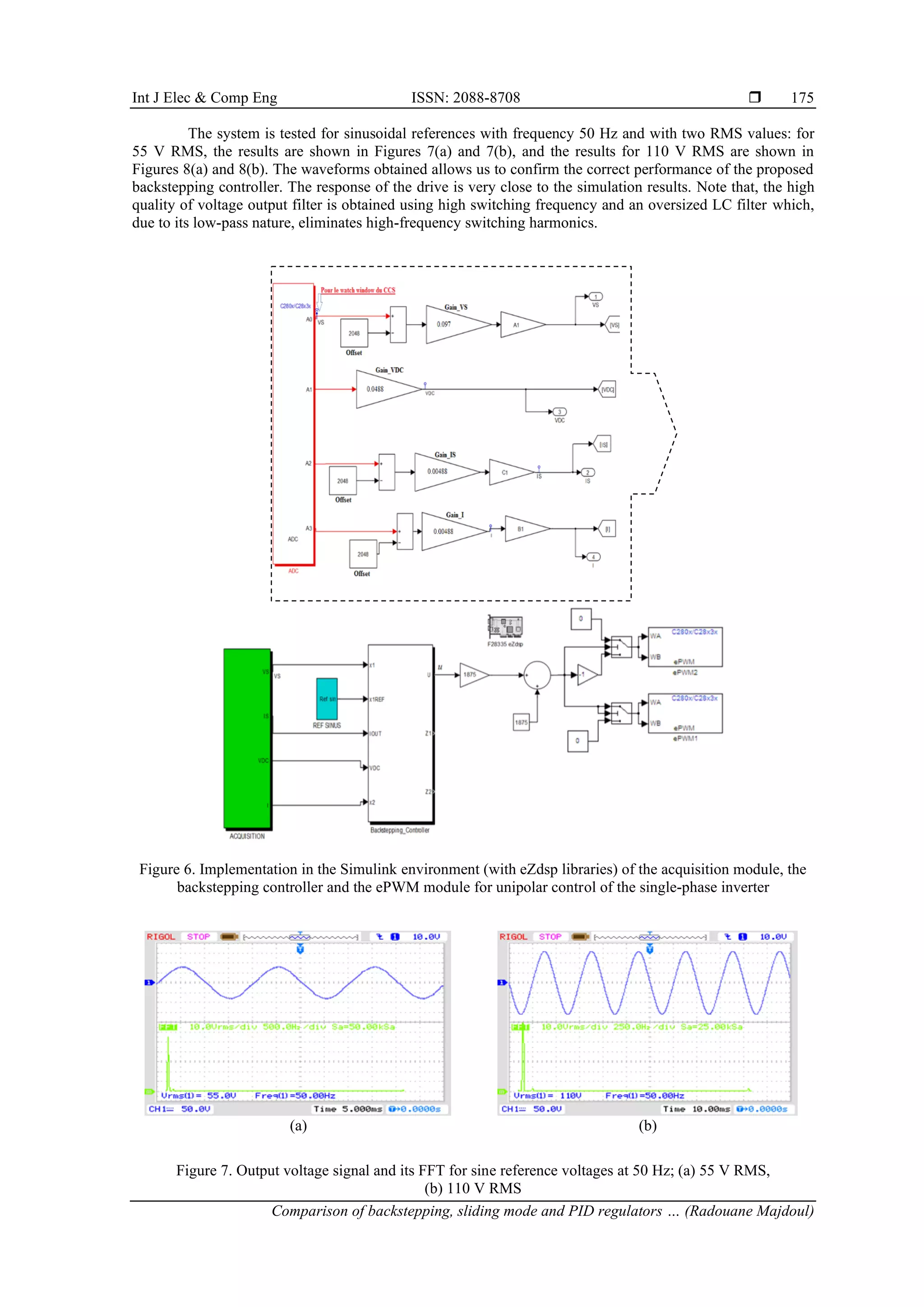
Figure 8. Output current signal for sine reference voltages at 50 Hz; (a) 55 V RMS, (b) 110 V RMS
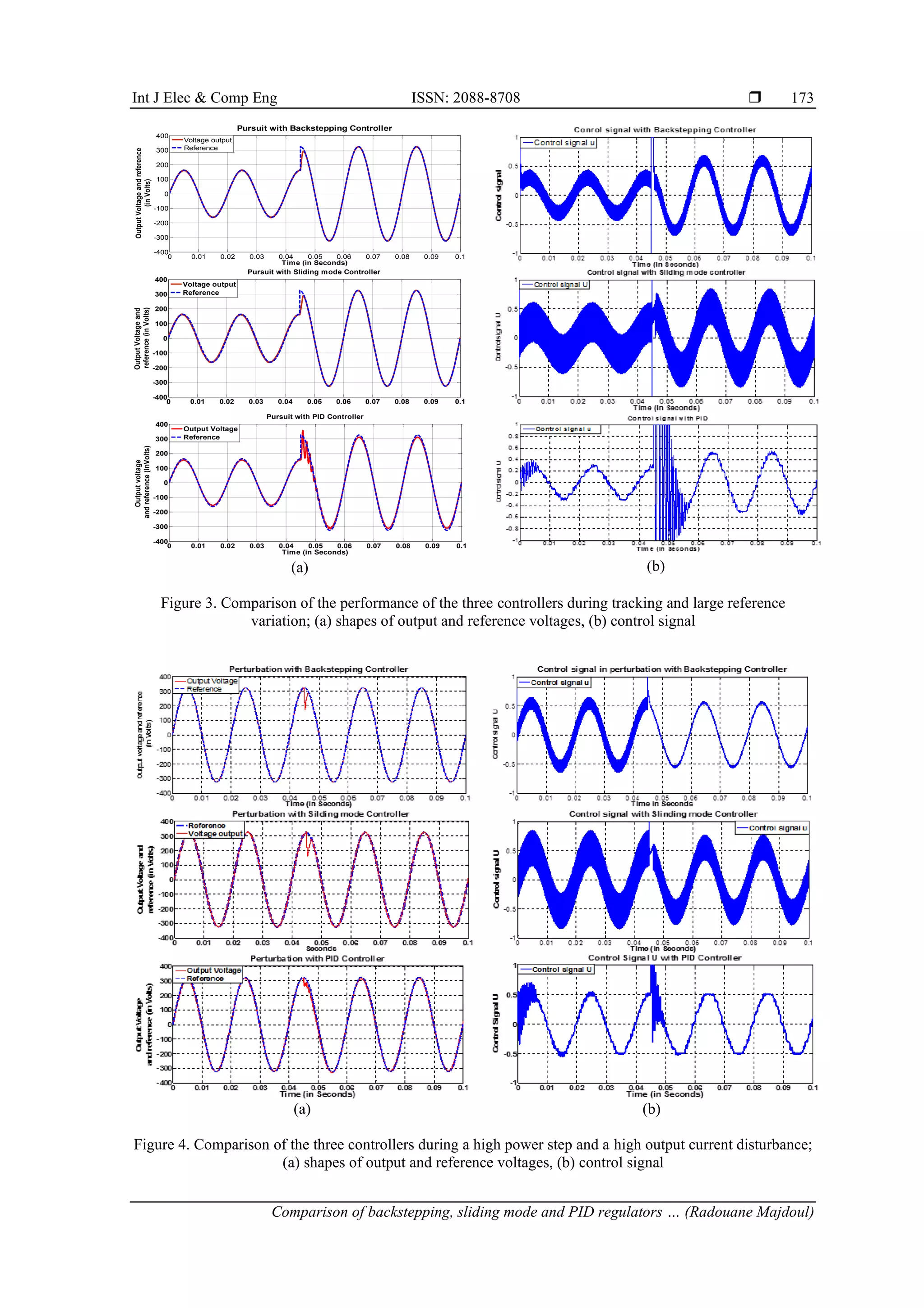
5. CONCLUSION
In this paper, we are interested in the study of the controller synthesis for DC-AC power converters.
Our purpose was twofold: i) to design, using three different approaches, a control law that stabilizes the
system, ensures good tracking of the output voltage of a sinusoidal reference variable, and provides correct
regulation in the presence of a large load variation; ii) to establish a comparative performance analysis of
three controllers: Backstepping, sliding mode, and PID, in order to determine which choice provides the best
performance. The simulation results show that the three controllers designed allow a good tracking and a
good regulation of the output voltage. However, it should be noted that it is the backstepping controller that
offers better performance: low response time and smoother control. The sliding mode regulator is also
powerful and fast, but unfortunately, its control is very harch. However, on the other hand, the PID has a
longer response time than the other two controllers. Also when the load or reference varies, the current in the
inductor is not controlled and may have a large overcurrent, which is another disadvantage for the PID. It is
important to note that the backstepping controller, with its good performance, has certain constraints during
its synthesis, which is done in several steps depending on the system to be controlled. Indeed, the ki synthesis
constants are not calculated mathematically but are chosen in an approximate way, and are only validated
after numerous tests and trials on the system. Further comparative studies between advanced adaptive
backstepping variants, second-order sliding mode and passivity-based controllers may enhance this work.
REFERENCES
[1] C. Kalavalli, K. P. Kathirvelu, and R. Balasubramanian, “Single phase bidirectional PWM converter for microgrid system,”
International Journal of Engineering and Technology (IJET), vol. 5, no. 3, pp. 2436–2441, Jun.-Jul. 2013.
[2] L. Xiangli and Q. Hanhong, “One-cycle controlled single phase UPS inverter,” ICSSDMS, Physics Procedia, vol. 25,
pp. 1048–1054, 2012, doi: 10.1016/j.phpro.2012.03.198.
[3] Y. Yang and F. Blaabjerg, “Overview of single-phase grid-connected photovoltaic systems,” Electric Power Components and
Systems, vol. 43, no 12, pp. 1352–1363, 2015, doi: 10.1080/15325008.2015.1031296.
[4] D. Picault, “Reduction of mismatch losses in grid-connected photovoltaic systems using alternative topologies,” Thesis presented
in National Polytechnic Institut of Grenoble, France, 2010.
[5] E. Tomaszewski and J. Jiangy, “An anti-windup scheme for proportional resonant controllers with tuneable phase-shift in voltage
source converters,” 2016 IEEE Power and Energy Society General Meeting (PESGM), Boston, MA, 2016, pp. 1–5,
doi: 10.1109/PESGM.2016.7741367.
[6] A. A. Nazeri, P. Zacharias, F. M. Ibanez, and S. Somkun, “Design of proportional-resonant controller with zero steady-state error
for a single-phase grid-connected voltage source inverter with an LCL output filter,” 2019 IEEE Milan PowerTech, Milan, Italy,
2019, pp. 1–6, doi: 10.1109/PTC.2019.8810554.
[7] A. Houari, “Contribution to the study of autonomous micro-grids powered by photovoltaic sources,” (in French), Thesis presented
in National Higher School of Electricity and Mecanic of Nancy, France, 2010.
[8] I. Aidi, M. Ayadi, M. Benrejeb, P. Borne., “Comparative performance of sliding mode and platitude control methods of a
motorized throttle valve,” (in French), e-STA 2010-2, vol. 7, no. 2, pp. 1–8, 2010.
[9] R. Bhatnagar, M. M. Anwer, and Manish, “Design and analytical comparison of various controllers used in PWM inverter,”
Internatonal Journal Research in Science Engineering and Technology (IJRSET), vol. 1, no. 3, pp. 07–012, 2012.
[10] A. Benaskeur, “Aspects of the application of adaptive backstepping to the decentralized control of nonlinear systems,” (in
French), Thesis in Laval University, Laval, Canada, 2000. [Online]. Available:
https://corpus.ulaval.ca/jspui/handle/20.500.11794/41020
[11] P. T. Krein, J. Bentsman, R. M. Bass, and B. L. Lesieutre, “On the use of averaging for analysis of power electronic system,”
IEEE Transaction on Power Electronics, vol. 5, no. 2, pp. 182–190, 1990, doi: 10.1109/63.53155.
[12] B. Lehman and R. M. Bass, “Switching frequency dependent averaged models for PWM DCDC converters,” IEEE Transaction
on Power Electronics, vol. 11, no. 1, pp. 89–98, 1996, doi: 10.1109/63.484421.
[13] M. Krstic, I. Kanellakopoulos, and P. V. Kokotovic, “Nonlinear design of adaptive controllers for linear systems,” IEEE
Transactions on Automatic Control, vol. 39, no. 4, pp. 738–752, 1994, doi: 10.1109/9.286250.](https://image.slidesharecdn.com/1824510emr20jul2febl-211206060822/75/Comparison-of-backstepping-sliding-mode-and-PID-regulators-for-a-voltage-inverter-11-2048.jpg)
![Int J Elec & Comp Eng ISSN: 2088-8708
Comparison of backstepping, sliding mode and PID regulators … (Radouane Majdoul)
177
[14] M. Krstic, I. Kanellakopoulos, and P. V. Kokotovic, “Nonlinear and adaptive control design,” John Willy & Sons, NY, 1995.
[15] R. Majdoul, A. Abouloifa, E. Abdelmounim, M. Aboulfatah, A. Touati, and A. Moutabir, “Backstepping controller of five-level
three-phase inverter,” MATEC Web of Conferences, EDP Sciences, vol. 16, May 2014, doi: 10.1051/matecconf/20141606003.
[16] Y. Fang, J. Fei, and T. Hu, “Adaptive backstepping fuzzy sliding mode vibration control of flexible structure,” Journal of Low
Frequency Noise, Vibration and Active Control, vol. 37, pp. 1079–1096, 2018, doi: 10.1177/1461348418767097.
[17] A. Taouni, A. Abbou, M. Akherraz, A. Ouchatti, and R. Majdoul, “MPPT design for system using backstepping control with
boost converter,” in International Renewable and Sustainable Energy Conference (IRSEC), Marrakech, Morocco, 2016,
pp. 469-475, doi: 10.1109/IRSEC.2016.7983920.
[18] M. Arsalan, R. Iftikhar, I. Ahmad, A. Hasan, K. Sabahat, and A. Javeria, “MPPT for photovoltaic system using nonlinear
backstepping controller with integral action,” Solar Energy, vol. 170, pp. 192–200, 2018, doi: 10.1016/j.solener.2018.04.061.
[19] Y. Fang, J. Fei, and Y. Yang, “Adaptive backstepping design of a microgyroscope,” Micromachines, vol. 9, no. 7, 2018,
Art. no. 338, doi: 10.3390/mi9070338.
[20] V. I. Utkin, “Sliding modes in control optimization,” Communication and Control Engineering Series, Springer-Verlag Berlin
Heidelberg, 1992, doi: 10.1007/978-3-642-84379-2.
[21] T. Abderrahim, T. Abdelwahed, and M. Radouane, “Improved strategy of an MPPT based on the sliding mode control for a PV
system,” International Journal of Electrical and Computer Engineering (IJECE), vol. 10, no. 3, pp. 3074–3085, Jun. 2020, doi:
10.11591/ijece.v10i3.pp3074-3085.
[22] Y. Zhu and J. Fei, “Disturbance observer based fuzzy sliding mode control of PV grid connected inverter,” in IEEE Access, vol. 6,
pp. 21202–21211, 2018, doi: 10.1109/ACCESS.2018.2825678.
[23] Y. Zhu and J. Fei, “Adaptive global fast terminal sliding mode control of grid-connected photovoltaic system using fuzzy neural
network approach,” in IEEE Access, vol. 5, pp. 9476–9484, 2017, doi: 10.1109/ACCESS.2017.2707668.
[24] T. Abdelwahed, M. Radouane, T. Abderrahim, M. Aboulfatah, and R. Nabila, “Comparative study between fast terminal and
second order sliding mode controls applied to a wind energy conversion system,” Indonesian Journal of Electrical Engineering
and Computer Science (IJEECS), vol. 22, no. 2, pp. 157-171, May 2021, doi: 10.11591/ijeecs.v22.i2.pp765-779.
[25] K. J. Astrom and T. Hagglund, “PID controllers: Theory, design and tuning,” Instrument Society of America, Research Triangle
Park, NC., 1995.
BIOGRAPHIES OF AUTHORS
Radouane Majdoul was born in Meknes, Morocco, in 1969. He received the
Engineer degree in electrical Engineering from High Institute of Technical Education
(ENSET) of Rabat in 1991. In 1997, he successfully passed the external aggregation contest.
In 2012 and 2017 he received respectively the M.Sc and Ph.D in Automatic Signal
Processing and Industrial Computing from HASSAN 1st
University – FST of Settat Morocco.
In 2018, he joined the Hassan 2 University of Casablanca, Morocco. Currently, he is
Research Professor in Laboratory of Structural Engineering, Intelligent Systems & Electrical
Energy at National High School of Arts and Crafts ENSAM, and Department of Electrical
Engineering. His research interests include control strategies for Power Electronics
Converters, Multilevel inverters, PV systems, AC machine Drives, renewable energy, Smart-
Grids, Power Quality and Power to X. He can be contacted at email:
radouane.majdoul@univh2c.ma
Abdelwahed Touati was born in Casablanca, Morocco, in 1970. He received
the Engineer degree in electrical Engineering from High Institute of Technical Education
(ENSET) of Mohammedia in 1993. In 1999, he successfully passed the external aggregation
contest. In 2012 he received the MASTER ATSII (Automatic Signal Processing and
Industrial Computing) from HASSAN 1 University – FST of SETTAT Morocco. Currently,
he is Research Professor in Laboratory of Structural Engineering, Intelligent Systems &
Electrical Energy at National High School of Arts and Crafts ENSAM, and Department of
Electrical Engineering - Hassan II University Casablanca, Morocco. His research interests
include control strategies for AC machine Drives, Wind renewable energy and Power
Quality. He can be contacted at email: touati_2010@hotmail.com
Abderrahmane Ouchatti was born Morocco in 1972. He received the Engineer
degree in electrical Engineering from High Institute of Technical Education (ENSET) of
Rabat in 1994. Received the Aggregation in Electrical Engineering from ENSET, Rabat, in
2000. He received the M.Sc in Automatic, Signal Processing and Industrial Computing from
HASSAN 1st
University – FST of Settat Morocco in 2011. He received in 2018, the Ph.D
degree in Industrial electronics and electrical machines from Engineering Mohammadia high
School of Rabat in Morocco. Currently he is Research Professor in Laboratory of Electrical
Systems & Control Engineering (ESCE) – Aïn Chock Science faculty of Casablanaca. His
research interests include control strategies for AC machine Drives, renewable energy and
Multilevel converters. He can be contacted at email: ouchatti_a@yahoo.fr](https://image.slidesharecdn.com/1824510emr20jul2febl-211206060822/75/Comparison-of-backstepping-sliding-mode-and-PID-regulators-for-a-voltage-inverter-12-2048.jpg)