
Recommended
Recommended
More Related Content
What's hot
What's hot (19)
Similar to Portfolio
Similar to Portfolio (20)
Recently uploaded
Recently uploaded (20)
Portfolio
- 1. MATT ROSSOW 1ST SEMESTER SOLIDWORKS PORTFOLIO Format: PART DESCRIPTION TOOLS & FEATURES USED KNOWLEDGE, SKILLS & ABILITIES OBTAINED
- 2. PLASTIC ENCLOSURE EXTRUSIONS CUT FILLET CHAMFER SHELL PHOTO RENDERING
- 3. WHEEL CASTER REVOLVE FEATURE MIRRORING SKETCHES/FEATURES RIB FEATURE CIRCULAR PATTERN PHOTO RENDERING
- 4. BOLT SCREW CREATING PARTS FROM BLUEPRINTS DOME FEATURE
- 5. RATCHET SECONDARY FEATURE MODELING OFFSET PLANES OFFSET EDGES SKETCH MIRROR EXTRUDE UP TO NEXT DRAFT ENGRAVING EMBOSSING TEXT
- 6. BRASS KEY PLATE MODELING FROM BLUEPRINT USING MATERIALS &MASS PROPERTIES TO DETERMINE WEIGHT&EVALUATE COSTS `
- 7. RUBBER WHEEL SWEEP FEATURE CREATING PLANES PERPENDICULAR TO GUIDE CURVES SKETCH CHAMFER CIRCULAR PATTERNS HOLE WIZARD FEATURE TO CREATE COUNTERBORE
- 8. COMPLEX PART FOR ASSEMBLY MODELING PARTS FROM A 2D PRINT FEATURE MIRRORING ABOUT CENTERLINES ADDING PARALLEL COINCIDENT REINFORCEMENT RIBS
- 9. BEZEL, BATTERY AND CIRCUIT BOARD ASSEMBLY CREATING AN ASSEMBLY (COVER MODELED. INTERNAL PARTS PROVIDED) USINGCONFIGURATION MANAGER TO CREATE MULTIPLE DISPLAY STATES ANIMATING AN EXPLOSION OR COLLAPSE CROSS SECTION VIEWS EXPLODED VIEWS EXPLODED LINE
- 10. BOTTOM UP ASSEMBLY MATING PARTS WORKING WITH DYNAMIC ASSEMBLY MOTION
- 11. CREATING DRAWINGS FROM PART FILES AUXILIARY VIEWS SECTION VIEWS DETAIL VIEWS BROKEN VIEWS LOCKING INTO VIEWS CROPPING VIEWS EDITING SHEET FORMAT MODIFYING PARTS FROM THE DRAWINGS ROTATING DIMENSIONS CENTERLINE ANNOTATIONS ORDINATE DIMENSIONS
- 12. CREATING DRAWINGS FROM PART FILES EDITING SHEET FORMAT ADJUSTING SCALE & FONTS ADJUSTING LEADERS CUSTOM DIMENSION TEXT
- 13. MIDTERM EXAM MODELING A BOTTLE& CAP CREATING AN ASSEMBLY EXPLODING AN ASSEMBLY CREATING A BLUEPRINT WITH FRONT, BOTTOM, SECTION, DETAIL & SHADED EXPLODED VIEWS INCLUDING BILL OF MATERIALS (NON-EXCEL BASED), CENTERMARKS, BALLOONS MODIFYING SHEET FORMAT FOR NOTATION SETTING TANGENT EDGES TO VISIBLE WITH FONT I took this test a week early and finished it in 5 minutes. The extra credit was for switching the perspective to 1st angle (UK standard) per instructions.
- 14. FINITE ELEMENT ANALYSIS A simple example of our intro to finite element analysis. The 3rd course in the certification will focus on simulations extensively and will involve creating reports to improve design (either to improve safety or determine where a part is over-engineered to reduce cost). Modeled a 1060 aluminum paper clip which has a yield strength of 27 MPa. For Comparison: human bone - 130 MPa, steel - 250 MPa, carbon fiber - 5500MPa Applied 5lbf to tip with fixture on bottom and animated deformation Yield Strength - Stress at which material begins to deform plastically Tensile Strength - Stress at which material breaks
- 15. FINITE ELEMENT ANALYSIS CONTINUED Deciding on a factor of safety (depending on application) Looking at the displacement measurement from the applied force
- 16. GRILL WITH 3D CURVES CURVE FEATURE SWEEP FEATURE 145°/35° REVOLVE OF CONCENTRIC RINGS MIRROR 3D Curve derived from 2 sketches Path for 2nd Sweep
- 17. TUBULAR FRAMED CHAIR 3D SKETCHING CREATING REFRENCE PLANES SWEEP FEATURE Reference plane for the profile Creating the sweep
- 18. LOFTED BOAT CREATING REFERENCE PLANES PASTING SKETCHES& MODIFYING DIMENSIONS LOFT TOOL WORK IN PROGRESS (DETAILING)
- 19. SMOKE DETECTOR FRONT BEZEL MODELING PARTS FROM 2D PRINTS CHAMFER SHELL CIRCULAR PATTERN TANGENT RELATION LINEAR PATTERN Circular pattern of a cut extruding to surface (sketch is tangent to edge)
- 20. SMOKE DETECTOR BACK COVER MODELING FROM 2D PRINT MODELING NON-UNIFORM SHELL OFFSET ENTITIES TOOL PATTERNING MULTIPLE FEATURES Sketching in wireframe for insert cutouts
- 21. TOP DOWN ASSEMBLY MODELING A PENCIL SHARPENER CREATING PARTS INSIDE AN ASSEMBLY MANAGING PART EDITS INSIDE AN ASSEMBLY BOSS EXTRUDE THIN FEATURE (TO CREATE LIP FOR COVER) Using convert entities to model a cover An on edge relationship allows changes for one part to update the entire assembly
- 22. TOP DOWN ASSEMBLY DRAWING INSPECTION DIMENSION NOTATION
- 23. MARKUP REVISIONS TAKING A WORK ORDER AND MAKING NECESSARY REVISIONS TO THE PART OR ASSEMBLY ADJUSTING DISPLAY STATES TO WORK ON INDIVIDUAL PARTS OR HIDE COMPONENTS Work order instructions Reinforcement ribs modeled. The placement was determined in wireframe and they were extruded to match/ fit the PCB fixture Modeling the LCD screen and extruding up to surface so it is flush with the front case
- 24. MODELING FROM DIMENSIONS, SKETCH OR BLUEPRINT HOLE WIZARD TO INSERT ¼” COUNTERBORE Sketching and dimensioning while proof checking dimensions with highlighter from print
- 25. TOP DOWN CREATION OFSHEET METAL GEARBOX COVER CREATING A COVER WITH THE PROVIDED FRAME AND GEARS OLDSCHOOL BEND AND FLATTEN TOOLS RELIEF CUT STYLE (OBROUND, TEAR, RECTANGULAR) SETTING BEND ALLOWANCE (K FACTOR) USING DESIGN LIBRARIES EXCEL BASED BILL OF MATERIALS EXPORTING FLATTENED FILES AS DXF OR DWG FOR CNC
- 26. SHEET METAL BRACKET HEM TOOL EDGE FLANGE TOOL SLOT TOOL
- 27. MODELING TIMER COVERFROM BLUEPRINT USING THE ROLLBACK BAR TO INSERT THEORETICAL SHARP CORNER DIMENSIONS POST FILLET
- 28. MODELING TIMER BACKPLATE FROM BLUEPRINT SHIFT SELECTING INTERIOR LOOPS TO CONVERT ENTITIES MIRRORING FOR EFFICIENCY Modeling a part from a blueprint using a dual screen external monitor
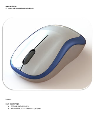
- 29. COMPUTER MOUSE SURFACING DIMENSIONING & ADDING RELATIONS TO SPLINE HANDLES SURFACE EXTRUDING SPLINES BOUNDARY SURFACING Step 1: A surface extrude is created based from the side profile of the mouse Step 2: The vertical shape of the base is trimmed from the bottom of the extrusion Step 3: Two construction surface extrudes are created with splines at the front and back Step 4: The base of the mouse can then be surfaced via Boundary Surfacing as seen above The height and angle of the top surface of the mouse is dimensioned 3d Sketch with coincident relations between base and top surface splines
- 30. COMPUTER MOUSE SURFACING CONVERTING ENTITIES IN 3D SKETCH CONSTRUCTION LINES WITH 3D SKETCHES TO TRIM FILLED SURFACE TOOL KNIT SURFACE TOOL Convert entities is used in 3d sketch on the previous 3d sketch and a vertical construction line is created to trim The model is mirrored once all boundary surfaces are created on one side Using the Filled Surface tool to create a bottom surface of the mouse by selecting the bottom edges The blue selected surfaces are knitted together after surface trimming a .2mm gap between each section
- 31. COMPUTER MOUSE DETAILING THICKEN TOOL TO CREATE SPECIFIC WALL THICKNESS The Thicken tool allows unique wall thicknesses to be created for each of the knitted sections Using the Selected Bodies option in a through all cut extrude to cut only the top knitted section of the mouse. The wheel is modeled with a midplane extrusion and a surface fillet after sketching on the front plane 1mm deep notches were created on the wheel with a revolved cut using a construction line as the axis This notch is circular patterned around the wheel
- 32. COMPUTER MOUSE COMPLETED & RENDERING
- 33. CLOCK ASSEMBLY MODELING A CLOCK BEZEL FROM DIMENSIONS CREATING AN ASSEMBLY EXPLODING THE ASSEMBLY CREATING A BLUEPRINT WITH SECTION VIEW, DETAIL VIEW, BILL OF MATERIALS, BALLOONS SCALING THE BLUEPRINT TO FIT THE PROPER SHEET SIZE