1. EME 150A F14
11/19/14
SolidWorks FEAAssignment 5
Due 12/5/14 by 5:00PM
Learning Goals:
Create Fatigue Study from Static Studies
Understand Fatigue Study Properties and
Options
Select Correct S-N Curves
Understand results of Fatigue Studies
Description:
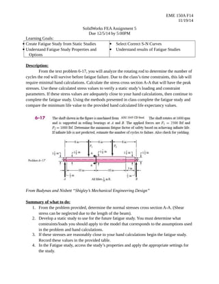
From the text problem 6-17, you will analyze the rotating rod to determine the number of
cycles the rod will survive before fatigue failure. Due to the class’s time constraints, this lab will
require minimal hand calculations. Calculate the stress cross section A-A that will have the peak
stresses. Use these calculated stress values to verify a static study’s loading and constraint
parameters. If these stress values are adequately close to your hand calculations, then continue to
complete the fatigue study. Using the methods presented in class complete the fatigue study and
compare the minimum life value to the provided hand calculated life expectancy values.
From Budynas and Nisbett “Shigley’s Mechanical Engineering Design”
Summary of what to do:
1. From the problem provided, determine the normal stresses cross section A-A. (Shear
stress can be neglected due to the length of the beam).
2. Develop a static study to use for the future fatigue study. You must determine what
constraints/loads you should apply to the model that corresponds to the assumptions used
in the problem and hand calculations.
3. If these stresses are reasonably close to your hand calculations begin the fatigue study.
Record these values in the provided table.
4. In the Fatigue study, access the study’s properties and apply the appropriate settings for
the study.
2. EME 150A F14
11/19/14
5. Apply the material’s S-N curve, as well as the loading event. The number of cycles will
not be of a concern for this study, due to no interest in damage results.
6. Produce a damage plot and a life plot as the results. Determine if this rod is a good design
of the rotating speed is 1600 rpm.
What to turn in:
1. Your CAD part file static and fatigue study completed.
a. Filename: LastName_FirstName
2. A word document with the following:
a. Abstract: a brief paragraph describing how your hand calculated normal stress
values compared to normal stress values of the static study. What types of
constraints/loads were applied, where mesh controls were placed, and what
parameters were used for the fatigue study. Explain any discrepancies your FEA
results have and why they would exist. As well, give your opinion on the quality
of this design given its rotating speed.
b. Filled in charts
Static Study
Max Stress at
A-A
Hand
Calculations
FEA
Error
Fatigue Study
Min Life
Expectancy
Hand
Calculations
5800 Cycles
FEA Study
Error