1. The Dynamic Airfoil Testing Apparatus
Student Team: Deep Singh, Gustavo Carvalho Grade Mancini, Karishma Chavda, Carter Bell, Anahita Yazdi
Faculty Mentor: Professor Steven A. Velinsky, Jean-Jacques Chattot
Project Sponsor: Robert Edwards (Advanced Modeling Aeronautics Team Captain)
ACKNOWLEDGEMENTS
We would like to thank Professor Steven Velinksy, Professor Jean-Jacques Chattot,
Professor Stephen Robinson, Professor Michael Hill, Professor Bruce White,
Mitchell Olson, Scott Block, Rachael Larson, Robert Edwards, AMAT and Arm
Control Team (ACT) for their knowledge and support throughout this project.
MATERIALS LIST PARTS
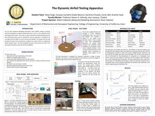
RESULTS
Department of Mechanical and Aerospace Engineering. College of Engineering. University of California, Davis
FINAL DESIGN - TEST STAND
Strain
Gauge
Amplifying
Circuit
Arduino
A/D
Converter
MATLAB Excel
The three graphs here represent Cd
and CL data obtained while testing in
the ABLWT. Data was collected using
angles of attack between -5˚ and 15˚.
Based on this data, the stall angle of
attack was found to be between 9˚
and 12˚. This data is representative
of the double element airfoil section
(seen in Figure 5), which the AMAT
team supplied.
INTRODUCTION
The UC Davis Advanced Modeling Aeronautics Team (AMAT) needed a dynamic
airfoil test apparatus to experimentally determine CL and CD, the coefficients of lift
and drag for their airfoil. There was no way for the team to experimentally confirm
their theoretical values prior to competition. This test apparatus is intended to be
an integral tool for AMAT to use for future airfoil designs. This project will also help
provide test data of the aerodynamic properties of a given airfoil, to supplement
AMAT’s design report. Our team designed and built a test stand to be used in the
Atmospheric Boundary-Layer Wind Tunnel (ABLWT).
DESIGN CRITERIA
The test stand must:
• Measure the lift and drag forces on the airfoil.
• Allow for a variable angle of attack.
• Collect data while airflow passes over test section.
• Be a modular test apparatus that can be used with a variety of airfoil sizes and
designs.
• Be simple to use and easy to modify.
• Minimize airflow disturbance due to test stand.
• Remain within the given $400 budget.
FINAL DESIGN - DATA AQUISTION
Figure 1: A flow chart showing the data acquisition
system.
Figure 2: The force experienced by the
airfoil is measured as a voltage change in
the strain gauges. This voltage difference
is amplified by the circuit and converted
The Spar attachment is designed for maximum resolution in angle of attack
variation. The slots cut in the PVC allow the hose clamps to secure set angles of
attack through contact friction against the spar.
The Center Upright Member fits
through a 6-inch diameter,
preexisting, hole in the floor of
the ABLWT. This member is
bolted to the Upper Cross
Member, which is free to rotate
in Front Side Parallelogram
Members. An inelastic cable
connects the cantilever beam
assembly to the bottom of the
Center Upright Member. There
are two connection points in this
member which correspond to
different stand angles, β (12˚
and 22˚).
Part Price Parts Price
Nuts/Bolts $22.24 PVC $4.99
Cable/Crimps $0.71 Hose Clamps $8.99
Bearings $73.12 Strain Gauges $29.20
Aluminum Flat bar $64.23 Op Amps $6.70
Aluminum Rod $11.11 Resistors $2.68
Aluminum Angle $39.89 Zener Diode *Donated
Steel Flat bar $6.20 Potentiometer *Donated
Particle Board $14.74 Arduino $49.95
TESTING
into a force in MATLAB. The force measurements are then exported to Excel and
decoupled into lift and drag. Then they are used to calculate the corresponding
coefficients. The zener diode was used as a safety measure protect Arduino from
receiving more than the maximum of 5V.
The total price of materials was $334.75. The addition of tax and shipping costs
still kept the total expense below the $400 limit. Aluminum flat bar was used for
all parallelogram members as well as the Center Upright Member. Aluminum rod
was used for the Upper and Lower Cross Members. The circular cross section of
this rod minimized air flow disturbance as compared to a rectangular cross
section. Steel was used instead of aluminum for the cantilever beam because it
has a more favorable elastic properties. The Spar attachments were made from
PVC because of its flexibility and durability. These are important properties for a
component that is to be clamped repeatedly. All members were machined in the
student Engineering and Fabrication Lab.
Figure 3.
Figure 4.
Figure 5.
Figure 3 shows group members Gustavo
and Deep adjusting β between trials. The
mount, during active testing, appears in
Figure 4. Finally, Figure 5 displays the
double element airfoil used during testing
as well as the Top Parallelogram Members
with the Spar Attachments.
The figure to the left illustrates the flow
velocity and disturbances inside the
tunnel. The orange points indicates
laminar uniform flow (about 4-5 m/s at
1250 RPM or 157-196 inches per
second) which is the ideal operating
conditions of the ABLWT. The figure
shows how the stand, without the
airfoil, influences the flow inside the
tunnel.