SlideShare a Scribd company logo
1 of 13
Download to read offline
(12) United States Patent
Dverin et al.
(54) DEVICE FOR RF HEATING AND
MECHANICAL MASSAGE OF BIOLOGICAL
TISSUE
(75) Inventors: Alexander Dverin, Netanya (IL);
Yevgeny Pens, Haifa (IL); Ziv Karni,
Kfar Shmaryahu (IL); Ziv Shabat,
Kibbutz Givat Haim Meuchad (IL);
Alexander Britva, Migdal Haemek (IL)
(73) Assignee: Alma Lasers Ltd, Caesarea (IL)
( *) Notice: Subject to any disclaimer, the term ofthis
patent is extended or adjusted under 35
U.S.c. 154(b) by 268 days.
(21) Appl. No.: 12/834,033
(22) Filed: Jui. 12, 2010
(65) Prior Publication Data
US 201110009783 Al Jan. 13, 2011
Related U.S. Application Data
(60) Provisional application No. 611224,883, filed on Jul.
12,2009.
(51) Int. CI.
A61H 15/00 (2006.01)
(52) U.S. CI.
USPC ........................................... 6011112; 6011113
(58) Field of Classification Search ................ 60117, 10,
601115, DIG. 1, DIG. 4, DIG. 5, 46, 123,
6011126,134,112,113; 607/101,115
See application file for complete search history.
111111 1111111111111111111111111111111111111111111111111111111111111
US008435194B2
(10) Patent No.: US 8,435,194 B2
May 7, 2013(45) Date of Patent:
(56) References Cited
U.S. PATENT DOCUMENTS
4,858,600 A
6,438,424 Bl
6,662,054 B2
6,673,096 B2
7,630,774 B2
7,762,964 B2 *
2007/0173749 Al *
2008/0183252 Al *
2008/0200778 Al *
200910171424 Al
8/1989 Gross et al.
8/2002 Knowlton
12/2003 Kreindel
112004 Lach
12/2009 Karni
7/2010 Slatkine ............................ 60117
7/2007 Williams et al. .............. 6011123
7/2008 Khen ............................ 607/101
8/2008 Taskinen et al. .............. 600/306
7/2009 Britva
FOREIGN PATENT DOCUMENTS
WO W098/05286 2/1998
* cited by examiner
Primary Examiner - Michael A. Brown
(74) Attorney, Agent, or Firm - Mark M. Friedman
(57) ABSTRACT
A skin treatment device combines an RF treatment arrange-
ment with a mechanical massage arrangement, preferably
with the massage device in the form of an annular massage
head encircling and rotating around the RF applicator. Also
disclosed are configurations with a liquid dispenser for deliv-
ering a liquid to the skin under the device. According to one
option, the skin contact surface of the RF applicator itself is
provided in part by a rolling ball liquid applicator.
23 Claims, 6 Drawing Sheets
u.s. Patent May 7, 2013 Sheet 1 of 6 US 8,435,194 B2
FIG. 1
24 10
40
/
36
20
14a -
18 16
u.s. Patent May 7, 2013 Sheet 2 of 6 US 8,435,194 B2
10
FIG. 2
I
33
32
40 -~~lU~~
50 --++~~ ===~
26
30
28
16 j" 18
u.s. Patent May 7, 2013 Sheet 3 of 6 US 8,435,194 B2
10
FIG.3 I
33
32
30
26
__-c::---- 14
18
12 /*
16
20
14a
u.s. Patent May 7, 2013 Sheet 4 of 6 US 8,435,194 B2
FIG.4
38
38a 14
18
20
I 16
12 46
u.s. Patent
FIG. 5
38
20
38a
38b
I
May 7, 2013
12 14a
Sheet 5 of 6 US 8,435,194 B2
14
48
18
16
u.s. Patent May 7, 2013 Sheet 6 of 6 US 8,435,194 B2
FIG.6
44
38a
14
46
US 8,435,194 B2
1
DEVICE FOR RF HEATING AND
MECHANICAL MASSAGE OF BIOLOGICAL
TISSUE
FIELD AND BACKGROUND OF THE
INVENTION
The present invention relates to apparatus and methods for
heating biological tissue using radio frequency (RF) electro-
magnetic waves.
It is known to employ electromagnetic energy for deliver-
ing energy into biological tissue. Of most relevance to the
present invention are devices which perform thermal treat-
ment ofthe skin by delivery ofRF energy. Examples believed
to be representative of the current state of the art for such
devices, the contents of which are hereby incorporated by
reference, include: u.s. Pat. No. 7,630,774, US20090171424
and u.s. Pat. No. 6,662,054.
In the field of massage devices, it is known to employ
spherical bodies mounted in a rotating structure to provide a
mechanical massage effect. An example ofsuch a device may
be found in u.s. Pat. No. 4,858,600, which is hereby incor-
porated by reference.
SUMMARY OF THE INVENTION
We now disclose that when RF energy is applied to treat
biological tissue (for example, skin), it is useful to apply
mechanical massage to the tissue in full or partial synchrony
with the RF treatment.
In some embodiments, this is carried out using a device
including a handpiece including: (i) an RF applicator; and (ii)
a "ring-shaped" massager which surrounds the RF applicator.
10
2
sage subsystem configured to mechanically massage the skin
under treatment and/or adjacent skin.
In one example, this modification is carried out so that a
given location on the skin is: (i) first subjected to massage; (ii)
then subjected to RF energy; and (iii) once again, subjected to
massage.
Thus, according to an embodiment ofthe present invention
there is provided, a skin treatment device comprising: (a) an
RF treatment arrangement comprising: (i) an RF applicator
terminating in a skin contact surface through which RF
energy is delivered into the skin, and (ii) an RF energy source
capable ofdirecting an RF power signal to the applicator; and
(b) a mechanical massage arrangement comprising: (i) a mas-
sage manipulator comprising at least one massage head, the
15 massage manipulator defining a skin contact region, and (ii) a
motor, mechanically linked in driving relation to the at least
one massage head so as to displace the at least one massage
head relative to a skin surface, wherein the skin contact region
substantially encircles the RF applicator such that, when the
20 device is brought in contact with the skin and the RF treat-
ment arrangement and the mechanical massage arrangement
are actuated, mechanical massage is performed on a region of
skin adjacent to, or overlapping with, a region treated by the
25
RF energy.
According to an embodiment ofthe present invention, the
at least one massage head is an annular massage head
deployed so as to encircle the RF applicator.
According to an embodiment ofthe present invention, the
annular massage head includes a plurality ofrolling elements
30 deployed to provide rolling engagement withthe skin surface.
According to an embodiment ofthe present invention, the
annular massage head includes a plurality of spherical ele-
ments deployed to provide rolling engagement with the skin
surface.
Although not a limitation, in some embodiments, this is 35
carried out using RF energy provided by any teaching or
combination of teachings disclosed in u.s. Pat. No. 7,630,
774.
According to an embodiment ofthe present invention, the
annular massage head is rotatably monnted so as to rotate
about an axis, and wherein the axis substantially coincides
with a central axis of the RF applicator.
Mechanical massage ofskin is known to affect dermal and
subcutaneous connective tissue, promoting blood flow,
relieving sore muscles and tension, and stimulating the
release of harmful toxins in the skin. Mechanical massage
enhances microcirculation and facilitates drainage oftrapped
intercellular fluid to the lymphatic system and may act to form
a callus ofthicker more hydrated subcutaneous tissue that has
a smoother contour due to fewer local depressions.
RF energy is known to affect the same regions ofthe skin,
progressively increasing heat-inducing thermal effects and
local metabolism. RF energy (for example, RF energy deliv-
ered in accordance with one or more teachings of U.s. Pat.
No. 7,630,774, or using a device operating according to one
ormore teachings ofU.S. Pat. No. 7,630,774) and mechanical
massage applied in near, partial, or full conjunction achieve a
synergy, non-limiting examples of which include improved
temporary reduction in the appearance ofcellulite, remodel-
ing of collagen, and alleviation of wrinkles.
According to an embodiment ofthe present invention, the
40 annular massage head is interconnected so as to rotate
together with a gear wheel, and wherein the gear wheel has a
central opening, at least part ofthe RF treatment arrangement
extending through the central opening.
According to an embodiment ofthe present invention, the
45 motor and the RF energy source are deployed within a com-
mon housing, and wherein the motor is provided with elec-
trical shielding.
According to an embodiment ofthe present invention, the
motor and the RF energy source are deployed within a com-
50 monhousing, the device further comprising a liquid dispenser
deployed at least partially within the housing and configured
to deliver a liquid to a region of skin underlying the device.
According to an embodiment ofthe present invention, the
liquid dispenser defines a flow path in thermal contact with at
55 least part of the RF applicator.
According to an embodiment of the present invention,
there is also provided a cooling arrangement deployed within
the housing and configured to cool the liquid, thereby cooling
the RF applicator.
According to an embodiment ofthe present invention, the
liquid dispenser defines a flow path passing through at least
part of the RF applicator.
In a non-limiting scenario, the device ofthe present inven-
tion is used as follows: (i) an RF applicator is placed in contact
with the skin surface; (ii) RF power is delivered from the
applicator to the skin, thereby heating underlying tissue lay- 60
ers; (iii) at least partially concomitant with the delivery of
RF-power, a massage applicator is applied to the skin, for
example a rotating ring of balls arranged around the RF
applicator, thereby massaging the underlying tissue layers.
According to an embodiment ofthe present invention, the
flow path extends to deliver the liquid at the skin contact
65 surface ofthe RF applicator.In a non-limiting example, we contemplate modifYing a
system for skin treatment having an RF subsystem, similar to
that disclosed in u.s. Pat. No. 7,630,774, to include a mas-
According to an embodiment ofthe present invention, the
flow path terminates at a rolling ball liquid applicator formed
US 8,435,194 B2
3
as part ofthe RF applicator so as to provide at least part ofthe
skin contact surface of the RF applicator.
According to an embodiment ofthe present invention, the
liquid dispenser defines a flow path extending through the
massage manipulator so as to deliver the liquid via the at least
one massage head.
According to an embodiment ofthe present invention, the
massage head includes a plurality of spherical elements
deployed to provide rolling engagement with the skin surface,
and wherein the flow path delivers the liquid to a surface ofat 10
least one of the spherical elements for rolling application to
the skin surface.
4
FIG. 1 is an isometric view ofa handpiece for treating skin
with RF power and mechanical massage, according to some
embodiments of the present invention, the device being
shown with a front part of a housing removed.
FIG. 2 is an isometric view ofcomponents ofthe handpiece
of FIG. 1.
FIG. 3 is a cut-away view of the components of FIG. 2.
FIG. 4 is an enlarged partial cross-sectional view of a
portion of the handpiece of FIG. 1 illustrating a first imple-
mentation ofa liquid dispensing flow path.
FIG. 5 is an enlarged partial cross-sectional view of a
portion ofthe handpiece ofFIG. 1 illustrating a secondimple-
mentation ofa liquid dispensing flow path.
FIG. 6 is an enlarged partial cross-sectional view of a
portion of a handpiece according to an alternative embodi-
ment of the present invention.
While the invention is described herein by way ofexample
for several embodiments and illustrative drawings, those
There is also provided according to an embodiment of the
present invention, a skin treatment device comprising: (a) a
housing; (b) an RF treatment arrangement deployed at least
partially within the housing, the RF treatment arrangement 15
comprising: (i) an RF applicator terminating in a skin contact
surface through which RF energy is delivered into the skin,
and (ii) an RF energy source capable ofdirecting an RF power
signal to the applicator; and (c) a liquid dispenser deployed at
least partially within the housing and configured to deliver a
liquid to a region of skin underlying the RF applicator.
20 skilled in the art will recognize that the invention is not
limited to the embodiments or drawings described. It should
be understood that the drawings and detailed description
thereto are not intended to limit the invention to the particular
form disclosed, but on the contrary, the invention is to cover
According to an embodiment ofthe present invention, the
liquid dispenser defines a flow path in thermal contact with at
least part of the RF applicator.
According to an embodiment of the present invention,
there is also provided a cooling arrangement deployed within
the housing and configured to cool the liquid, thereby cooling
the RF applicator.
25 all modifications, equivalents and alternatives falling within
the scope ofthe present invention as defined by the appended
claims.
According to an embodiment ofthe present invention, the
liquid dispenser defines a flow path passing through at least 30
part of the RF applicator.
According to an embodiment ofthe present invention, the
flow path terminates at a rolling ball liquid applicator formed
as part ofthe RF applicator so as to provide at least part ofthe
skin contact surface of the RF applicator.
According to an embodiment of the present invention, 35
there is also provided a mechanical massage arrangement
comprising: (a) a massage manipulator comprising at least
one massage head, the massage manipulator defining a skin
contact region, and (b) a motor, mechanically linked in driv-
ing relation to the at least one massage head so as to displace 40
the at least one massage head relative to a skin surface,
wherein the skin contact region substantially encircles the RF
applicator such that, when the device is brought in contact
with the skin and the RF treatment arrangement and the
mechanical massage arrangement are actuated, mechanical 45
massage is performed on a region of skin adjacent to, or
overlapping with, a region treated by the RF energy.
According to an embodiment ofthe present invention, the
at least one massage head is an annular massage head
deployed so as to encircle the RF applicator.
According to an embodiment ofthe present invention, the 50
annular massage head includes a plurality of spherical ele-
ments deployed to provide rolling engagement with the skin
surface.
According to an embodiment ofthe present invention, the
liquid dispenser defines a flow path extending through the 55
massage manipulator so as to deliver the liquid to a surface of
at least one ofthe spherical elements for rolling application to
the skin surface.
According to an embodiment ofthe present invention, the
annular massage head is rotatably mounted so as to rotate 60
about an axis, and wherein the axis substantially coincides
with a central axis of the RF applicator.
BRIEF DESCRIPTION OF THE DRAWINGS
DESCRIPTION OF THE PREFERRED
EMBODIMENTS
The invention is herein described, by way ofexample only,
with reference to the accompanying drawings. With specific
reference now to the drawings in detail, it is stressed that the
particulars shown are by way ofexample and for purposes of
illustrative discussion of the preferred embodiments of the
exemplary system only, and are presented in the cause of
providing what is believed to be the most useful and readily
understood description of the principles and conceptual
aspects ofthe invention. In this regard, no attempt is made to
show structural details ofthe invention in more detail than is
necessary for a fundamental understanding of the invention,
the description taken with the drawings making apparent to
those skilled in the art how several forms ofthe invention may
be embodied in practice.
By way ofintroduction, the present invention has a number
of different aspects, each of which is believed to be of indi-
vidual importance, but which may be used together in par-
ticular synergy. A first aspect of the invention relates to a
combination skin treatment device which performs simulta-
neous mechanical massage and RF energy treatment. A sec-
ond aspect ofthe invention relates to a device which delivers
a liquid (cream, gel, ointment, paste or other fluid substance)
to the skin contact surface ofa skin treatment device with RF
energy treatment. FIGS. 1-5 relate to an illustrative embodi-
ment in which both ofthese aspects are combined in synergy,
while FIG. 6 presents an alternative embodiment in which the
liquid delivery aspect is implemented without mechanical
massage.
Combination RF Energy and Mechanical Massage
Turning now to the drawings, FIGS. 1-5 illustrate a skin
treatment device, preferably implemented as a "handpiece"
10, in accordance with some embodiments of the present
invention, that is intended for integration in a system for skin
The invention is herein described, by way ofexample only,
with reference to the accompanying drawings, wherein:
65 treatment. The system for skin treatment includes an RF
energy subsystem terminating in an RF applicator 14 and a
massage subsystem terminating in a massage applicator 12.
US 8,435,194 B2
5
In more detail, the RF energy subsystem (also referred to as
an "RF treatment arrangement") includes RF applicator 14
terminating in a skin contact surface 14a through which RF
energy is delivered into the skin, and an RF energy source 40
configured to direct an RF power signal to applicator 14.
6
as to avoid interactions with the RF energy near RF applicator
14. A non-limiting example of a suitable material is an insu-
lating, biocompatible, lightweight, low-friction, and wear-
resistant thermoplastic such as polyoxymethylene (marketed
as DELRIN® by the E.!. du Pont de Nemours and Company
of DE, USA.), or other plastics, ceramics or the like. Non-
limiting exemplary dimensions for the massage subsystem
are: a 50 mmdiameterofring 18, a 10 mmdiameterofball16,
and a ring 18 rotation speed of 150 rpm. Optionally, it may be
RF skin treatment systems per se are well developed, and
are readily commercially available. Examples of commer-
cially available RF treatment systems which could readily be
modified according to the teachings of the present invention
includeAccent XL system available from ALMA Lasers Ltd.
(Israel), andVelashape and Velasmooth available from SYN-
ERON Ltd. (Israel). For conciseness of this disclosure, fea-
tures ofthe RF treatment subsystem that are not new will not
10 advantageous to operate the massage head at a rate ofrotation
which is synchronized with a pulse width modulation (PWM)
frequency of the RF treatment, for example, at the same
frequency, or where one is an integer multiple of the other.
be described here. Massage head 12 is rotated by motor 32 by engagement of
15 a drive gear 30 of motor 32 with a gear wheel 26 intercon-
nected so as to rotate together with ring 18. Gear wheel 26 as
shown here is monnted on a bearing 28 located at a central
opening of the gear wheel through which at least part of the
By way ofa non-limiting but particularly preferred imple-
mentation, the RF energy subsystem may be implemented as
described in u.s. Pat. No. 7,630,774, which is hereby incor-
porated by reference in its entirety. In this case, substantially
the entire skin contact surface 14a of the RF applicator 14
serves as a single electrode for delivering the RF energy into 20
the skin. It should be noted however that systems with two or
more electrodes may also be used to implement the present
invention. In certain cases, skin contact surface 14a may be
split into two concentric electrode regions.
RE applicator 14 is typically roughly symmetrical about a 25
central axis 42 that, when extrapolated, also corresponds
roughly to the center of the RF treatment region for the
current position of the device.
RF treatment arrangement extends.
Power for motor 32 and RF energy for the RF applicator 14
are supplied via supply tube 33. When motor 32 is powered,
it turns drive gear 30, which turns gear 26, turning ring 18 and
balls 16, which massage an annular area of skin around the
area in contact with the RF applicator 14.
Electric motor 32 and RF source 40 are preferably housed
in a common housing 34. Electric motor 32 is preferably
provided with electrical shielding in order to minimize RE
interference on the massage subsystem. Motor 32 may be a
readily commercially available shielded DC brushless motor.Turning now to the massage subsystem (also referred to as
a "mechanical massage arrangement"), massage applicator
12 is preferably implemented as a massage manipulator with
at least one massage head. In this context, the term "massage
head" refers to a moving body with features, or rolling sub-
elements, which perform a massage function as is moves in
contact with the skin. The one or more massage heads define
a skin contact region of the massage manipulator, i.e., the
region ofthe skin that will be treated with massage by opera-
tion ofthe massage heads while the device is maintained in a
given position in contact with the skin. A motor 32 is
mechanically linked in driving relation to the at least one
massage head so as to displace the at least one massage head
relative to a skin surface.
30 For safety, motor 32 can be operable to detect changes in
resistance to rotation of ring 18, to adjust its input current to
compensate for such changes in resistance, and to interrupt its
input current if resistance exceeds a defined threshold.
RF applicator 14 and massage applicator 12 are preferably
35 arranged such that when the handpiece 10 is positioned for
treating an area of a subject's skin, each applicator is in
contact with the skin. During treatment, the skin treatment
system supplies RF energy through RF applicator 14 to the
skin and mechanical force through massage applicator 12 to
40 the skin.
It is a particular feature of certain embodiments of the
present invention that the skin contact region substantially
encircles the RF applicator such that, when device 10 is 45
brought in contact with the skinandthe RF treatment arrange-
ment and the mechanical massage arrangement are actuated,
mechanical massage is performed on a region ofskin adjacent
to, or overlapping with, a region treated by the RF energy. It
should be mentioned that the device is particularly suited to 50
in-motion treatment where the handpiece is drawn across the
skin surface during use. This typically results in a treatment
sequence in which the skin passing under the device is mas-
saged, then heated and then massaged again.
In a particularly preferred implementation as illustrated 55
here, massage applicator 12 is implemented as a single annu-
lar massage head (or"ring") 18 deployed so as to encircle part
ofRF applicator 14, and is rotatably mounted so as to rotate
about an axis, that may be substantially coinciding with the
central axis 42 of the RF applicator. The annular massage 60
head preferably includes a plurality ofrolling elements, most
preferably spherical elements (balls) 16, deployed to provide
rolling engagement with the skin surface.
The balls 16 are preferably retained by a faceplate 20 ofthe
massage head which has openings through which balls 16 65
project. The various parts of massage head 18 and balls 16
may be made from any suitable material, preferably chosen so
The massage applicator 12 and the RE applicator 14 can be
activated separately or simultaneously. In one non-limiting
scenario, the massage applicator 12 is operated continuously
while the device is in use, and the RE energy is selectively
actuated by an operator actuating a button or trigger 24 on the
device. Typically, the applicators are activated simulta-
neously as handpiece 10 is moved over the skin surface, for
example, in circular motion, across a desired treatment area,
for example, a rectangular area, until RF applicator 14 has
applied a predetermined amonnt of energy to the treatment
area.
In a non-limiting example, a 450 square cm treatment area
of a subject's posterior thigh is treated by RE applicator 14
supplied with 120Wto 160Wat40.68MHzuntil60kJto 100
kJ of total energy have been emitted. Concurrently massage
applicator 12 is rotated at 150 revolutions per minute, mas-
saging the skin.
The arrangement of massage applicator 12 annularly
aronnd RF applicator 14 ensures that no matter which direc-
tion handpiece lOis moved, skin passes under massage appli-
cator 12 immediately before and after it passes under RF
applicator 14, contributing to the effective synergy ofthe two
applications. Furthermore, without in any way limiting the
scope ofthe present invention, in certain preferred implemen-
tations where a continuous-rotation massage motion used, it
is believed that this motion is particularly effective at induc-
ing a net flow of body fluids in the region nndergoing mas-
US 8,435,194 B2
7
sage, thereby effectively mobilizing body fluids and enhanc-
ing uniformity of the RF treatment.
In some embodiments, handpiece 10 further comprises a
skin detector operative to detect physical characteristics of
the skin in contact with massage applicator 16 and a control
circuit operative to alter the ring rotation speed according to
input from the skin detector.
In some embodiments, handpiece 10 comprises a velocity
detector operative to detect the handpiece velocity and a
control circuit operative to alter the ring 18 rotation speed 10
according to input from the velocity detector.
Combination RF Energy and Liquid Dispensing
Turning now to a second aspect of the present invention,
this relates to dispensing ofa liquid to the skin contact surface
of a skin treatment device which performs RF energy treat- 15
ment. As mentioned above, this feature may be used to advan-
tage in synergy with the RF-and-massage combination
described above. Accordingly, this aspect of the invention
will be described primarily with reference to FIGS. 1-5 in a
combined embodiment. Thereafter, brief reference will be 20
made to FIG. 6 which relates to an implementation of this
second aspect ofthe invention without a massage applicator.
Referring now again to FIG. 1, according to an embodi-
ment of the invention, the device includes a liquid dispenser
36 deployed at least partially within housing 34 and config- 25
ured to deliver a liquid along a flow path 38 to a region ofskin
underlying the device, i.e., within the outer perimeter of the
skin contact region of massage applicator 12, whether actu-
ally in the skin contact region of the massage system or the
skin contact region of the RF applicator, or therebetween. 30
Although not limited to any particular liquid, this aspect of
the present invention is believed to be ofparticular advantage
when implemented using oil. Specifically, the oil serves to
lubricate contact between the RF applicator and/or massage
applicator against the skin, and may help to disperse heat at 35
the skin surface, rendering the treatment more uniform.
Optionally, mineral oil or other oils or lotions providing a
soothing effect and/or other beneficial effects to the skin may
be used.
In certain preferred implementations ofthe RF subsystem, 40
a cooling arrangement, typically employing thermoelectric
coolers (TEC) 50 (FIG. 2), is deployed to cool RF applicator
14 to below body temperature. According to an optional fea-
ture of the present invention, a part of flow path 38 (denoted
38a) is deployed in thermal contact with at least part ofthe RF 45
applicator. Flow path 38a may pass adjacent to the outside
surface ofRF applicator 14, or as shown in the examples of
FIGS. 4 and 5, may pass within RF applicator 14. A cooling
arrangement 44 (preferably TEC-based) is deployed within
housing 34 so as to cool the liquid. The liquid flowing through 50
flow path 38a then contributes to the overall cooling of RF
applicator 14.
8
plastics. Alternatively, other non-magnetic metals, such as
copper, stainless steel, brass, bronze, and beryllium brass,
may be used. An insulating coating is desirable for decreasing
the likelihood ofspark generation, and for homogenization of
the RF current distribution.
Turning now to FIG. 5, this shows an alternative imple-
mentation in which a part of flow path 38, designated 38b,
extends through rotating massage applicator 12 to dispense
the liquid via the rotating balls 16 of the massage device.
Connection between the non-rotating flow path 38a and the
rotating part of the flow path 38b may be achieved at an
annular manifold 48 extending aronnd the periphery of RF
applicator 14.
Turning finally to FIG. 6, as mentioned earlier, the liquid
dispensing aspect ofthe present invention may also be used to
advantage in an RF energy skin treatment device which does
not include a massage subsystem. FIG. 6 illustrates schemati-
cally the terminal portion of the RF applicator 14 of such an
implementation. The structure and function of the device
shown is fully analogous to that of FIG. 4 described above,
with similar components being labeled similarly, and need
not be described again.
It will be appreciated that the above descriptions are
intended only to serve as examples, and that many other
embodiments are possible within the scope of the present
invention as defined in the appended claims.
What is claimed is:
1. A skin treatment device comprising:
(a) an RF treatment arrangement comprising:
(i) an RF applicator terminating in a skin contact surface
through which RF energy is delivered into the skin,
and
(ii) an RF energy source capable of directing an RF
power signal to said applicator; and
(b) a mechanical massage arrangement comprising:
(i) a massage manipulator comprising at least one annu-
lar massage head deployed so as to encircle said RF
applicator, said massage manipulator defining a skin
contact region, and
(ii) a motor, mechanically linked in driving relation to
said at least one massage head so as to displace said at
least one massage head relative to a skin surface,
wherein said skin contact region substantially encircles
said RF applicator such that, when the device is brought
in contact with the skin and said RF treatment arrange-
ment and said mechanical massage arrangement are
actuated, mechanical massage is performed on a region
of skin adjacent to, or overlapping with, a region treated
by the RF energy,
and wherein said annular massage head is rotatably mounted
so as to rotate about an axis, and wherein said axis substan-
tially coincides with a central axis of said RF applicator.
2. The skin treatment device ofclaim 1, wherein said annu-
FIG. 4 illustrates one particularly preferred option for
implementing flow path 38a according to which the flow path
extends to deliver the liquid at the skin contact surface ofthe
RF applicator. In the example illustrated here, the flow path
terminates at a rolling ball liquid applicator formed as part of
the RF applicator so as to provide at least part ofa skincontact
surface of the RF applicator. This ensures that the liquid is
dispensed exactly at the skin contact surface ofRF applicator
14.
55 lar massage head is interconnected so as to rotate together
with a gear wheel, and wherein said gear wheel has a central
opening, at least part of said RF treatment arrangement
extending through said central opening.
3. The skin treatment device ofclaim 1, wherein said motor
60 and said RF energy source are deployed within a common
housing, and wherein said motor is provided with electrical
shielding.The rolling ball liquid applicator is typically implemented
using one or more balls 46 retained within, but projecting
from, the tip ofthe RF applicator. Byway ofone non-limiting
example, as with the main body ofRF applicator 14, ball 46 65
may be formed from aluminum coated with aluminum oxide
or some other insulating material such as Teflon or other
4. A skin treatment device comprising:
(a) an RF treatment arrangement comprising:
(i) an RF applicator terminating in a skin contact surface
through which RF energy is delivered into the skin,
and
US 8,435,194 B2
9
(ii) an RF energy source capable of directing an RF
power signal to said applicator; and
(b) a mechanical massage arrangement comprising:
(i) a massage manipulator comprising at least one annu-
lar massage head deployed so as to encircle said RF
applicator, said annular massage head including a
plurality ofrolling elements deployed to provide roll-
ing engagement with the skin surface, said massage
manipulator defining a skin contact region, and
(ii) a motor, mechanically linked in driving relation to 10
said at least one massage head so as to displace said at
least one massage head relative to a skin surface,
wherein said skin contact region substantially encircles
said RF applicator such that, when the device is brought
in contact with the skin and said RF treatment arrange- 15
ment and said mechanical massage arrangement are
actuated, mechanical massage is performed on a region
ofskin adjacent to, or overlapping with, a region treated
by the RF energy.
5. The skin treatment device ofclaim 4, wherein said plu- 20
rality of rolling elements are implemented as a plurality of
spherical elements deployed to provide rolling engagement
with the skin surface.
6. A skin treatment device comprising:
(a) an RF treatment arrangement comprising: 25
10
12. The skin treatment device of claim 6, wherein said
liquid dispenser defines a flow path extending through said
massage manipulator so as to deliver the liquid via said at
least one massage head.
13. The skin treatment device of claim 12, wherein said
massage head includes a plurality of spherical elements
deployed to provide rolling engagement withthe skin surface,
and wherein said flow path delivers the liquid to a surface of
at least one of said spherical elements for rolling application
to the skin surface.
14. A skin treatment device comprising:
(a) a housing;
(b) an RF treatment arrangement deployed at least partially
within said housing, the RF treatment arrangement com-
prising:
(i) an RF applicator terminating in a skin contact surface
through which RF energy is delivered into the skin,
and
(ii) an RF energy source capable of directing an RF
power signal to said applicator; and
(c) a liquid dispenser deployed at least partially within said
housing and configured to deliver a liquid to a region of
skin nnderlying said RF applicator.
15. The skin treatment device of claim 14, wherein said
liquid dispenser defines a flow path in thermal contact with at
least part of said RF applicator.
(i) an RF applicator terminating in a skin contact surface
through which RF energy is delivered into the skin,
and
(ii) an RF energy source capable of directing an RF
power signal to said applicator; and
16. The skin treatment device ofclaim 15, further compris-
ing a cooling arrangement deployed within said housing and
30 configured to cool the liquid, thereby cooling said RF appli-
(b) a mechanical massage arrangement comprising:
(i) a massage manipulator comprising at least one annu-
lar massage head deployed so as to encircle said RF
applicator, said massage manipulator defining a skin
contact region, and
(ii) a motor, mechanically linked in driving relation to
said at least one massage head so as to displace said at
least one massage head relative to a skin surface,
35
wherein said skin contact region substantially encircles
said RF applicator such that, when the device is brought 40
in contact with the skin and said RF treatment arrange-
ment and said mechanical massage arrangement are
actuated, mechanical massage is performed on a region
ofskin adjacent to, or overlapping with, a region treated
by the RF energy,
and wherein said motor and said RF energy source are
deployed within a common housing, the device further
comprising a liquid dispenser deployed at least partially
within said housing and configured to deliver a liquid to
a region of skin nnderlying the device.
7. The skin treatment device ofclaim 6, wherein said liquid
dispenser defines a flow path in thermal contact with at least
part of said RF applicator.
8. The skin treatment device ofclaim 7, further comprising
45
50
a cooling arrangement deployed within said housing and 55
configured to cool the liquid, thereby cooling said RF appli-
cator.
17. The skin treatment device of claim 14, wherein said
liquid dispenser defines a flow path passing through at least
part of said RF applicator.
18. The skin treatment device of claim 17, wherein said
flow path terminates at a rolling ball liquid applicator formed
as part ofsaid RF applicator so as to provide at least part ofthe
skin contact surface of said RF applicator.
19. The skin treatment device ofclaim 14, further compris-
ing a mechanical massage arrangement comprising:
(a) a massage manipulator comprising at least one massage
head, said massage manipulator defining a skin contact
region, and
(b) a motor, mechanically linked in driving relation to said
at least one massage head so as to displace said at least
one massage head relative to a skin surface,
wherein said skin contact region substantially encircles
said RF applicator such that, when the device is brought
in contact with the skin and said RF treatment arrange-
ment and said mechanical massage arrangement are
actuated, mechanical massage is performed on a region
of skin adjacent to, or overlapping with, a region treated
by the RF energy.
20. The skin treatment device of claim 19, wherein said at
least one massage head is an annular massage head deployed
so as to encircle said RF applicator.
cator.
9. The skin treatment device ofclaim 6, wherein said liquid
dispenser defines a flow path passing through at least part of
said RF applicator.
21. The skin treatment device of claim 20, wherein said
annular massage head includes a plurality of spherical ele-
ments deployed to provide rolling engagement with the skin
60 surface.
10. The skin treatment device ofclaim 9, wherein said flow
path extends to deliver the liquid at the skin contact surface of
said RF applicator.
11. The skin treatment device ofclaim 9, wherein said flow
path terminates at a rolling ball liquid applicator formed as
part of said RF applicator so as to provide at least part of the
skin contact surface of said RF applicator.
22. The skin treatment device of claim 21, wherein said
liquid dispenser defines a flow path extending through said
massage manipulator so as to deliver the liquid to a surface of
at least one of said spherical elements for rolling application
65 to the skin surface.
23. The skin treatment device of claim 20, wherein said
annular massage head is rotatably monnted so as to rotate
US 8,435,194 B2
11
about an axis, and wherein said axis substantially coincides
with a central axis of said RF applicator.
* * * * *
12

More Related Content

Featured

Everything You Need To Know About ChatGPT
Everything You Need To Know About ChatGPTEverything You Need To Know About ChatGPT
Everything You Need To Know About ChatGPTExpeed Software
 
Product Design Trends in 2024 | Teenage Engineerings
Product Design Trends in 2024 | Teenage EngineeringsProduct Design Trends in 2024 | Teenage Engineerings
Product Design Trends in 2024 | Teenage EngineeringsPixeldarts
 
How Race, Age and Gender Shape Attitudes Towards Mental Health
How Race, Age and Gender Shape Attitudes Towards Mental HealthHow Race, Age and Gender Shape Attitudes Towards Mental Health
How Race, Age and Gender Shape Attitudes Towards Mental HealthThinkNow
 
AI Trends in Creative Operations 2024 by Artwork Flow.pdf
AI Trends in Creative Operations 2024 by Artwork Flow.pdfAI Trends in Creative Operations 2024 by Artwork Flow.pdf
AI Trends in Creative Operations 2024 by Artwork Flow.pdfmarketingartwork
 
PEPSICO Presentation to CAGNY Conference Feb 2024
PEPSICO Presentation to CAGNY Conference Feb 2024PEPSICO Presentation to CAGNY Conference Feb 2024
PEPSICO Presentation to CAGNY Conference Feb 2024Neil Kimberley
 
Content Methodology: A Best Practices Report (Webinar)
Content Methodology: A Best Practices Report (Webinar)Content Methodology: A Best Practices Report (Webinar)
Content Methodology: A Best Practices Report (Webinar)contently
 
How to Prepare For a Successful Job Search for 2024
How to Prepare For a Successful Job Search for 2024How to Prepare For a Successful Job Search for 2024
How to Prepare For a Successful Job Search for 2024Albert Qian
 
Social Media Marketing Trends 2024 // The Global Indie Insights
Social Media Marketing Trends 2024 // The Global Indie InsightsSocial Media Marketing Trends 2024 // The Global Indie Insights
Social Media Marketing Trends 2024 // The Global Indie InsightsKurio // The Social Media Age(ncy)
 
Trends In Paid Search: Navigating The Digital Landscape In 2024
Trends In Paid Search: Navigating The Digital Landscape In 2024Trends In Paid Search: Navigating The Digital Landscape In 2024
Trends In Paid Search: Navigating The Digital Landscape In 2024Search Engine Journal
 
5 Public speaking tips from TED - Visualized summary
5 Public speaking tips from TED - Visualized summary5 Public speaking tips from TED - Visualized summary
5 Public speaking tips from TED - Visualized summarySpeakerHub
 
ChatGPT and the Future of Work - Clark Boyd
ChatGPT and the Future of Work - Clark Boyd ChatGPT and the Future of Work - Clark Boyd
ChatGPT and the Future of Work - Clark Boyd Clark Boyd
 
Getting into the tech field. what next
Getting into the tech field. what next Getting into the tech field. what next
Getting into the tech field. what next Tessa Mero
 
Google's Just Not That Into You: Understanding Core Updates & Search Intent
Google's Just Not That Into You: Understanding Core Updates & Search IntentGoogle's Just Not That Into You: Understanding Core Updates & Search Intent
Google's Just Not That Into You: Understanding Core Updates & Search IntentLily Ray
 
Time Management & Productivity - Best Practices
Time Management & Productivity -  Best PracticesTime Management & Productivity -  Best Practices
Time Management & Productivity - Best PracticesVit Horky
 
The six step guide to practical project management
The six step guide to practical project managementThe six step guide to practical project management
The six step guide to practical project managementMindGenius
 
Beginners Guide to TikTok for Search - Rachel Pearson - We are Tilt __ Bright...
Beginners Guide to TikTok for Search - Rachel Pearson - We are Tilt __ Bright...Beginners Guide to TikTok for Search - Rachel Pearson - We are Tilt __ Bright...
Beginners Guide to TikTok for Search - Rachel Pearson - We are Tilt __ Bright...RachelPearson36
 
Unlocking the Power of ChatGPT and AI in Testing - A Real-World Look, present...
Unlocking the Power of ChatGPT and AI in Testing - A Real-World Look, present...Unlocking the Power of ChatGPT and AI in Testing - A Real-World Look, present...
Unlocking the Power of ChatGPT and AI in Testing - A Real-World Look, present...Applitools
 

Featured (20)

Everything You Need To Know About ChatGPT
Everything You Need To Know About ChatGPTEverything You Need To Know About ChatGPT
Everything You Need To Know About ChatGPT
 
Product Design Trends in 2024 | Teenage Engineerings
Product Design Trends in 2024 | Teenage EngineeringsProduct Design Trends in 2024 | Teenage Engineerings
Product Design Trends in 2024 | Teenage Engineerings
 
How Race, Age and Gender Shape Attitudes Towards Mental Health
How Race, Age and Gender Shape Attitudes Towards Mental HealthHow Race, Age and Gender Shape Attitudes Towards Mental Health
How Race, Age and Gender Shape Attitudes Towards Mental Health
 
AI Trends in Creative Operations 2024 by Artwork Flow.pdf
AI Trends in Creative Operations 2024 by Artwork Flow.pdfAI Trends in Creative Operations 2024 by Artwork Flow.pdf
AI Trends in Creative Operations 2024 by Artwork Flow.pdf
 
Skeleton Culture Code
Skeleton Culture CodeSkeleton Culture Code
Skeleton Culture Code
 
PEPSICO Presentation to CAGNY Conference Feb 2024
PEPSICO Presentation to CAGNY Conference Feb 2024PEPSICO Presentation to CAGNY Conference Feb 2024
PEPSICO Presentation to CAGNY Conference Feb 2024
 
Content Methodology: A Best Practices Report (Webinar)
Content Methodology: A Best Practices Report (Webinar)Content Methodology: A Best Practices Report (Webinar)
Content Methodology: A Best Practices Report (Webinar)
 
How to Prepare For a Successful Job Search for 2024
How to Prepare For a Successful Job Search for 2024How to Prepare For a Successful Job Search for 2024
How to Prepare For a Successful Job Search for 2024
 
Social Media Marketing Trends 2024 // The Global Indie Insights
Social Media Marketing Trends 2024 // The Global Indie InsightsSocial Media Marketing Trends 2024 // The Global Indie Insights
Social Media Marketing Trends 2024 // The Global Indie Insights
 
Trends In Paid Search: Navigating The Digital Landscape In 2024
Trends In Paid Search: Navigating The Digital Landscape In 2024Trends In Paid Search: Navigating The Digital Landscape In 2024
Trends In Paid Search: Navigating The Digital Landscape In 2024
 
5 Public speaking tips from TED - Visualized summary
5 Public speaking tips from TED - Visualized summary5 Public speaking tips from TED - Visualized summary
5 Public speaking tips from TED - Visualized summary
 
ChatGPT and the Future of Work - Clark Boyd
ChatGPT and the Future of Work - Clark Boyd ChatGPT and the Future of Work - Clark Boyd
ChatGPT and the Future of Work - Clark Boyd
 
Getting into the tech field. what next
Getting into the tech field. what next Getting into the tech field. what next
Getting into the tech field. what next
 
Google's Just Not That Into You: Understanding Core Updates & Search Intent
Google's Just Not That Into You: Understanding Core Updates & Search IntentGoogle's Just Not That Into You: Understanding Core Updates & Search Intent
Google's Just Not That Into You: Understanding Core Updates & Search Intent
 
How to have difficult conversations
How to have difficult conversations How to have difficult conversations
How to have difficult conversations
 
Introduction to Data Science
Introduction to Data ScienceIntroduction to Data Science
Introduction to Data Science
 
Time Management & Productivity - Best Practices
Time Management & Productivity -  Best PracticesTime Management & Productivity -  Best Practices
Time Management & Productivity - Best Practices
 
The six step guide to practical project management
The six step guide to practical project managementThe six step guide to practical project management
The six step guide to practical project management
 
Beginners Guide to TikTok for Search - Rachel Pearson - We are Tilt __ Bright...
Beginners Guide to TikTok for Search - Rachel Pearson - We are Tilt __ Bright...Beginners Guide to TikTok for Search - Rachel Pearson - We are Tilt __ Bright...
Beginners Guide to TikTok for Search - Rachel Pearson - We are Tilt __ Bright...
 
Unlocking the Power of ChatGPT and AI in Testing - A Real-World Look, present...
Unlocking the Power of ChatGPT and AI in Testing - A Real-World Look, present...Unlocking the Power of ChatGPT and AI in Testing - A Real-World Look, present...
Unlocking the Power of ChatGPT and AI in Testing - A Real-World Look, present...
 

8435194 Patent

  • 1. (12) United States Patent Dverin et al. (54) DEVICE FOR RF HEATING AND MECHANICAL MASSAGE OF BIOLOGICAL TISSUE (75) Inventors: Alexander Dverin, Netanya (IL); Yevgeny Pens, Haifa (IL); Ziv Karni, Kfar Shmaryahu (IL); Ziv Shabat, Kibbutz Givat Haim Meuchad (IL); Alexander Britva, Migdal Haemek (IL) (73) Assignee: Alma Lasers Ltd, Caesarea (IL) ( *) Notice: Subject to any disclaimer, the term ofthis patent is extended or adjusted under 35 U.S.c. 154(b) by 268 days. (21) Appl. No.: 12/834,033 (22) Filed: Jui. 12, 2010 (65) Prior Publication Data US 201110009783 Al Jan. 13, 2011 Related U.S. Application Data (60) Provisional application No. 611224,883, filed on Jul. 12,2009. (51) Int. CI. A61H 15/00 (2006.01) (52) U.S. CI. USPC ........................................... 6011112; 6011113 (58) Field of Classification Search ................ 60117, 10, 601115, DIG. 1, DIG. 4, DIG. 5, 46, 123, 6011126,134,112,113; 607/101,115 See application file for complete search history. 111111 1111111111111111111111111111111111111111111111111111111111111 US008435194B2 (10) Patent No.: US 8,435,194 B2 May 7, 2013(45) Date of Patent: (56) References Cited U.S. PATENT DOCUMENTS 4,858,600 A 6,438,424 Bl 6,662,054 B2 6,673,096 B2 7,630,774 B2 7,762,964 B2 * 2007/0173749 Al * 2008/0183252 Al * 2008/0200778 Al * 200910171424 Al 8/1989 Gross et al. 8/2002 Knowlton 12/2003 Kreindel 112004 Lach 12/2009 Karni 7/2010 Slatkine ............................ 60117 7/2007 Williams et al. .............. 6011123 7/2008 Khen ............................ 607/101 8/2008 Taskinen et al. .............. 600/306 7/2009 Britva FOREIGN PATENT DOCUMENTS WO W098/05286 2/1998 * cited by examiner Primary Examiner - Michael A. Brown (74) Attorney, Agent, or Firm - Mark M. Friedman (57) ABSTRACT A skin treatment device combines an RF treatment arrange- ment with a mechanical massage arrangement, preferably with the massage device in the form of an annular massage head encircling and rotating around the RF applicator. Also disclosed are configurations with a liquid dispenser for deliv- ering a liquid to the skin under the device. According to one option, the skin contact surface of the RF applicator itself is provided in part by a rolling ball liquid applicator. 23 Claims, 6 Drawing Sheets
  • 2. u.s. Patent May 7, 2013 Sheet 1 of 6 US 8,435,194 B2
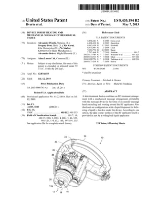
 FIG. 1 24 10 40 / 36 20 14a - 18 16
  • 3. u.s. Patent May 7, 2013 Sheet 2 of 6 US 8,435,194 B2 10 FIG. 2 I 33 32 40 -~~lU~~ 50 --++~~ ===~ 26 30 28 16 j" 18
  • 4. u.s. Patent May 7, 2013 Sheet 3 of 6 US 8,435,194 B2 10 FIG.3 I 33 32 30 26 __-c::---- 14 18 12 /* 16 20 14a
  • 5. u.s. Patent May 7, 2013 Sheet 4 of 6 US 8,435,194 B2 FIG.4 38 38a 14 18 20 I 16 12 46
  • 6. u.s. Patent FIG. 5 38 20 38a 38b I May 7, 2013 12 14a Sheet 5 of 6 US 8,435,194 B2 14 48 18 16
  • 7. u.s. Patent May 7, 2013 Sheet 6 of 6 US 8,435,194 B2 FIG.6 44 38a 14 46
  • 8. US 8,435,194 B2 1 DEVICE FOR RF HEATING AND MECHANICAL MASSAGE OF BIOLOGICAL TISSUE FIELD AND BACKGROUND OF THE INVENTION The present invention relates to apparatus and methods for heating biological tissue using radio frequency (RF) electro- magnetic waves. It is known to employ electromagnetic energy for deliver- ing energy into biological tissue. Of most relevance to the present invention are devices which perform thermal treat- ment ofthe skin by delivery ofRF energy. Examples believed to be representative of the current state of the art for such devices, the contents of which are hereby incorporated by reference, include: u.s. Pat. No. 7,630,774, US20090171424 and u.s. Pat. No. 6,662,054. In the field of massage devices, it is known to employ spherical bodies mounted in a rotating structure to provide a mechanical massage effect. An example ofsuch a device may be found in u.s. Pat. No. 4,858,600, which is hereby incor- porated by reference. SUMMARY OF THE INVENTION We now disclose that when RF energy is applied to treat biological tissue (for example, skin), it is useful to apply mechanical massage to the tissue in full or partial synchrony with the RF treatment. In some embodiments, this is carried out using a device including a handpiece including: (i) an RF applicator; and (ii) a "ring-shaped" massager which surrounds the RF applicator. 10 2 sage subsystem configured to mechanically massage the skin under treatment and/or adjacent skin. In one example, this modification is carried out so that a given location on the skin is: (i) first subjected to massage; (ii) then subjected to RF energy; and (iii) once again, subjected to massage. Thus, according to an embodiment ofthe present invention there is provided, a skin treatment device comprising: (a) an RF treatment arrangement comprising: (i) an RF applicator terminating in a skin contact surface through which RF energy is delivered into the skin, and (ii) an RF energy source capable ofdirecting an RF power signal to the applicator; and (b) a mechanical massage arrangement comprising: (i) a mas- sage manipulator comprising at least one massage head, the 15 massage manipulator defining a skin contact region, and (ii) a motor, mechanically linked in driving relation to the at least one massage head so as to displace the at least one massage head relative to a skin surface, wherein the skin contact region substantially encircles the RF applicator such that, when the 20 device is brought in contact with the skin and the RF treat- ment arrangement and the mechanical massage arrangement are actuated, mechanical massage is performed on a region of skin adjacent to, or overlapping with, a region treated by the 25 RF energy. According to an embodiment ofthe present invention, the at least one massage head is an annular massage head deployed so as to encircle the RF applicator. According to an embodiment ofthe present invention, the annular massage head includes a plurality ofrolling elements 30 deployed to provide rolling engagement withthe skin surface. According to an embodiment ofthe present invention, the annular massage head includes a plurality of spherical ele- ments deployed to provide rolling engagement with the skin surface. Although not a limitation, in some embodiments, this is 35 carried out using RF energy provided by any teaching or combination of teachings disclosed in u.s. Pat. No. 7,630, 774. According to an embodiment ofthe present invention, the annular massage head is rotatably monnted so as to rotate about an axis, and wherein the axis substantially coincides with a central axis of the RF applicator. Mechanical massage ofskin is known to affect dermal and subcutaneous connective tissue, promoting blood flow, relieving sore muscles and tension, and stimulating the release of harmful toxins in the skin. Mechanical massage enhances microcirculation and facilitates drainage oftrapped intercellular fluid to the lymphatic system and may act to form a callus ofthicker more hydrated subcutaneous tissue that has a smoother contour due to fewer local depressions. RF energy is known to affect the same regions ofthe skin, progressively increasing heat-inducing thermal effects and local metabolism. RF energy (for example, RF energy deliv- ered in accordance with one or more teachings of U.s. Pat. No. 7,630,774, or using a device operating according to one ormore teachings ofU.S. Pat. No. 7,630,774) and mechanical massage applied in near, partial, or full conjunction achieve a synergy, non-limiting examples of which include improved temporary reduction in the appearance ofcellulite, remodel- ing of collagen, and alleviation of wrinkles. According to an embodiment ofthe present invention, the 40 annular massage head is interconnected so as to rotate together with a gear wheel, and wherein the gear wheel has a central opening, at least part ofthe RF treatment arrangement extending through the central opening. According to an embodiment ofthe present invention, the 45 motor and the RF energy source are deployed within a com- mon housing, and wherein the motor is provided with elec- trical shielding. According to an embodiment ofthe present invention, the motor and the RF energy source are deployed within a com- 50 monhousing, the device further comprising a liquid dispenser deployed at least partially within the housing and configured to deliver a liquid to a region of skin underlying the device. According to an embodiment ofthe present invention, the liquid dispenser defines a flow path in thermal contact with at 55 least part of the RF applicator. According to an embodiment of the present invention, there is also provided a cooling arrangement deployed within the housing and configured to cool the liquid, thereby cooling the RF applicator. According to an embodiment ofthe present invention, the liquid dispenser defines a flow path passing through at least part of the RF applicator. In a non-limiting scenario, the device ofthe present inven- tion is used as follows: (i) an RF applicator is placed in contact with the skin surface; (ii) RF power is delivered from the applicator to the skin, thereby heating underlying tissue lay- 60 ers; (iii) at least partially concomitant with the delivery of RF-power, a massage applicator is applied to the skin, for example a rotating ring of balls arranged around the RF applicator, thereby massaging the underlying tissue layers. According to an embodiment ofthe present invention, the flow path extends to deliver the liquid at the skin contact 65 surface ofthe RF applicator.In a non-limiting example, we contemplate modifYing a system for skin treatment having an RF subsystem, similar to that disclosed in u.s. Pat. No. 7,630,774, to include a mas- According to an embodiment ofthe present invention, the flow path terminates at a rolling ball liquid applicator formed
  • 9. US 8,435,194 B2 3 as part ofthe RF applicator so as to provide at least part ofthe skin contact surface of the RF applicator. According to an embodiment ofthe present invention, the liquid dispenser defines a flow path extending through the massage manipulator so as to deliver the liquid via the at least one massage head. According to an embodiment ofthe present invention, the massage head includes a plurality of spherical elements deployed to provide rolling engagement with the skin surface, and wherein the flow path delivers the liquid to a surface ofat 10 least one of the spherical elements for rolling application to the skin surface. 4 FIG. 1 is an isometric view ofa handpiece for treating skin with RF power and mechanical massage, according to some embodiments of the present invention, the device being shown with a front part of a housing removed. FIG. 2 is an isometric view ofcomponents ofthe handpiece of FIG. 1. FIG. 3 is a cut-away view of the components of FIG. 2. FIG. 4 is an enlarged partial cross-sectional view of a portion of the handpiece of FIG. 1 illustrating a first imple- mentation ofa liquid dispensing flow path. FIG. 5 is an enlarged partial cross-sectional view of a portion ofthe handpiece ofFIG. 1 illustrating a secondimple- mentation ofa liquid dispensing flow path. FIG. 6 is an enlarged partial cross-sectional view of a portion of a handpiece according to an alternative embodi- ment of the present invention. While the invention is described herein by way ofexample for several embodiments and illustrative drawings, those There is also provided according to an embodiment of the present invention, a skin treatment device comprising: (a) a housing; (b) an RF treatment arrangement deployed at least partially within the housing, the RF treatment arrangement 15 comprising: (i) an RF applicator terminating in a skin contact surface through which RF energy is delivered into the skin, and (ii) an RF energy source capable ofdirecting an RF power signal to the applicator; and (c) a liquid dispenser deployed at least partially within the housing and configured to deliver a liquid to a region of skin underlying the RF applicator. 20 skilled in the art will recognize that the invention is not limited to the embodiments or drawings described. It should be understood that the drawings and detailed description thereto are not intended to limit the invention to the particular form disclosed, but on the contrary, the invention is to cover According to an embodiment ofthe present invention, the liquid dispenser defines a flow path in thermal contact with at least part of the RF applicator. According to an embodiment of the present invention, there is also provided a cooling arrangement deployed within the housing and configured to cool the liquid, thereby cooling the RF applicator. 25 all modifications, equivalents and alternatives falling within the scope ofthe present invention as defined by the appended claims. According to an embodiment ofthe present invention, the liquid dispenser defines a flow path passing through at least 30 part of the RF applicator. According to an embodiment ofthe present invention, the flow path terminates at a rolling ball liquid applicator formed as part ofthe RF applicator so as to provide at least part ofthe skin contact surface of the RF applicator. According to an embodiment of the present invention, 35 there is also provided a mechanical massage arrangement comprising: (a) a massage manipulator comprising at least one massage head, the massage manipulator defining a skin contact region, and (b) a motor, mechanically linked in driv- ing relation to the at least one massage head so as to displace 40 the at least one massage head relative to a skin surface, wherein the skin contact region substantially encircles the RF applicator such that, when the device is brought in contact with the skin and the RF treatment arrangement and the mechanical massage arrangement are actuated, mechanical 45 massage is performed on a region of skin adjacent to, or overlapping with, a region treated by the RF energy. According to an embodiment ofthe present invention, the at least one massage head is an annular massage head deployed so as to encircle the RF applicator. According to an embodiment ofthe present invention, the 50 annular massage head includes a plurality of spherical ele- ments deployed to provide rolling engagement with the skin surface. According to an embodiment ofthe present invention, the liquid dispenser defines a flow path extending through the 55 massage manipulator so as to deliver the liquid to a surface of at least one ofthe spherical elements for rolling application to the skin surface. According to an embodiment ofthe present invention, the annular massage head is rotatably mounted so as to rotate 60 about an axis, and wherein the axis substantially coincides with a central axis of the RF applicator. BRIEF DESCRIPTION OF THE DRAWINGS DESCRIPTION OF THE PREFERRED EMBODIMENTS The invention is herein described, by way ofexample only, with reference to the accompanying drawings. With specific reference now to the drawings in detail, it is stressed that the particulars shown are by way ofexample and for purposes of illustrative discussion of the preferred embodiments of the exemplary system only, and are presented in the cause of providing what is believed to be the most useful and readily understood description of the principles and conceptual aspects ofthe invention. In this regard, no attempt is made to show structural details ofthe invention in more detail than is necessary for a fundamental understanding of the invention, the description taken with the drawings making apparent to those skilled in the art how several forms ofthe invention may be embodied in practice. By way ofintroduction, the present invention has a number of different aspects, each of which is believed to be of indi- vidual importance, but which may be used together in par- ticular synergy. A first aspect of the invention relates to a combination skin treatment device which performs simulta- neous mechanical massage and RF energy treatment. A sec- ond aspect ofthe invention relates to a device which delivers a liquid (cream, gel, ointment, paste or other fluid substance) to the skin contact surface ofa skin treatment device with RF energy treatment. FIGS. 1-5 relate to an illustrative embodi- ment in which both ofthese aspects are combined in synergy, while FIG. 6 presents an alternative embodiment in which the liquid delivery aspect is implemented without mechanical massage. Combination RF Energy and Mechanical Massage Turning now to the drawings, FIGS. 1-5 illustrate a skin treatment device, preferably implemented as a "handpiece" 10, in accordance with some embodiments of the present invention, that is intended for integration in a system for skin The invention is herein described, by way ofexample only, with reference to the accompanying drawings, wherein: 65 treatment. The system for skin treatment includes an RF energy subsystem terminating in an RF applicator 14 and a massage subsystem terminating in a massage applicator 12.
  • 10. US 8,435,194 B2 5 In more detail, the RF energy subsystem (also referred to as an "RF treatment arrangement") includes RF applicator 14 terminating in a skin contact surface 14a through which RF energy is delivered into the skin, and an RF energy source 40 configured to direct an RF power signal to applicator 14. 6 as to avoid interactions with the RF energy near RF applicator 14. A non-limiting example of a suitable material is an insu- lating, biocompatible, lightweight, low-friction, and wear- resistant thermoplastic such as polyoxymethylene (marketed as DELRIN® by the E.!. du Pont de Nemours and Company of DE, USA.), or other plastics, ceramics or the like. Non- limiting exemplary dimensions for the massage subsystem are: a 50 mmdiameterofring 18, a 10 mmdiameterofball16, and a ring 18 rotation speed of 150 rpm. Optionally, it may be RF skin treatment systems per se are well developed, and are readily commercially available. Examples of commer- cially available RF treatment systems which could readily be modified according to the teachings of the present invention includeAccent XL system available from ALMA Lasers Ltd. (Israel), andVelashape and Velasmooth available from SYN- ERON Ltd. (Israel). For conciseness of this disclosure, fea- tures ofthe RF treatment subsystem that are not new will not 10 advantageous to operate the massage head at a rate ofrotation which is synchronized with a pulse width modulation (PWM) frequency of the RF treatment, for example, at the same frequency, or where one is an integer multiple of the other. be described here. Massage head 12 is rotated by motor 32 by engagement of 15 a drive gear 30 of motor 32 with a gear wheel 26 intercon- nected so as to rotate together with ring 18. Gear wheel 26 as shown here is monnted on a bearing 28 located at a central opening of the gear wheel through which at least part of the By way ofa non-limiting but particularly preferred imple- mentation, the RF energy subsystem may be implemented as described in u.s. Pat. No. 7,630,774, which is hereby incor- porated by reference in its entirety. In this case, substantially the entire skin contact surface 14a of the RF applicator 14 serves as a single electrode for delivering the RF energy into 20 the skin. It should be noted however that systems with two or more electrodes may also be used to implement the present invention. In certain cases, skin contact surface 14a may be split into two concentric electrode regions. RE applicator 14 is typically roughly symmetrical about a 25 central axis 42 that, when extrapolated, also corresponds roughly to the center of the RF treatment region for the current position of the device. RF treatment arrangement extends. Power for motor 32 and RF energy for the RF applicator 14 are supplied via supply tube 33. When motor 32 is powered, it turns drive gear 30, which turns gear 26, turning ring 18 and balls 16, which massage an annular area of skin around the area in contact with the RF applicator 14. Electric motor 32 and RF source 40 are preferably housed in a common housing 34. Electric motor 32 is preferably provided with electrical shielding in order to minimize RE interference on the massage subsystem. Motor 32 may be a readily commercially available shielded DC brushless motor.Turning now to the massage subsystem (also referred to as a "mechanical massage arrangement"), massage applicator 12 is preferably implemented as a massage manipulator with at least one massage head. In this context, the term "massage head" refers to a moving body with features, or rolling sub- elements, which perform a massage function as is moves in contact with the skin. The one or more massage heads define a skin contact region of the massage manipulator, i.e., the region ofthe skin that will be treated with massage by opera- tion ofthe massage heads while the device is maintained in a given position in contact with the skin. A motor 32 is mechanically linked in driving relation to the at least one massage head so as to displace the at least one massage head relative to a skin surface. 30 For safety, motor 32 can be operable to detect changes in resistance to rotation of ring 18, to adjust its input current to compensate for such changes in resistance, and to interrupt its input current if resistance exceeds a defined threshold. RF applicator 14 and massage applicator 12 are preferably 35 arranged such that when the handpiece 10 is positioned for treating an area of a subject's skin, each applicator is in contact with the skin. During treatment, the skin treatment system supplies RF energy through RF applicator 14 to the skin and mechanical force through massage applicator 12 to 40 the skin. It is a particular feature of certain embodiments of the present invention that the skin contact region substantially encircles the RF applicator such that, when device 10 is 45 brought in contact with the skinandthe RF treatment arrange- ment and the mechanical massage arrangement are actuated, mechanical massage is performed on a region ofskin adjacent to, or overlapping with, a region treated by the RF energy. It should be mentioned that the device is particularly suited to 50 in-motion treatment where the handpiece is drawn across the skin surface during use. This typically results in a treatment sequence in which the skin passing under the device is mas- saged, then heated and then massaged again. In a particularly preferred implementation as illustrated 55 here, massage applicator 12 is implemented as a single annu- lar massage head (or"ring") 18 deployed so as to encircle part ofRF applicator 14, and is rotatably mounted so as to rotate about an axis, that may be substantially coinciding with the central axis 42 of the RF applicator. The annular massage 60 head preferably includes a plurality ofrolling elements, most preferably spherical elements (balls) 16, deployed to provide rolling engagement with the skin surface. The balls 16 are preferably retained by a faceplate 20 ofthe massage head which has openings through which balls 16 65 project. The various parts of massage head 18 and balls 16 may be made from any suitable material, preferably chosen so The massage applicator 12 and the RE applicator 14 can be activated separately or simultaneously. In one non-limiting scenario, the massage applicator 12 is operated continuously while the device is in use, and the RE energy is selectively actuated by an operator actuating a button or trigger 24 on the device. Typically, the applicators are activated simulta- neously as handpiece 10 is moved over the skin surface, for example, in circular motion, across a desired treatment area, for example, a rectangular area, until RF applicator 14 has applied a predetermined amonnt of energy to the treatment area. In a non-limiting example, a 450 square cm treatment area of a subject's posterior thigh is treated by RE applicator 14 supplied with 120Wto 160Wat40.68MHzuntil60kJto 100 kJ of total energy have been emitted. Concurrently massage applicator 12 is rotated at 150 revolutions per minute, mas- saging the skin. The arrangement of massage applicator 12 annularly aronnd RF applicator 14 ensures that no matter which direc- tion handpiece lOis moved, skin passes under massage appli- cator 12 immediately before and after it passes under RF applicator 14, contributing to the effective synergy ofthe two applications. Furthermore, without in any way limiting the scope ofthe present invention, in certain preferred implemen- tations where a continuous-rotation massage motion used, it is believed that this motion is particularly effective at induc- ing a net flow of body fluids in the region nndergoing mas-
  • 11. US 8,435,194 B2 7 sage, thereby effectively mobilizing body fluids and enhanc- ing uniformity of the RF treatment. In some embodiments, handpiece 10 further comprises a skin detector operative to detect physical characteristics of the skin in contact with massage applicator 16 and a control circuit operative to alter the ring rotation speed according to input from the skin detector. In some embodiments, handpiece 10 comprises a velocity detector operative to detect the handpiece velocity and a control circuit operative to alter the ring 18 rotation speed 10 according to input from the velocity detector. Combination RF Energy and Liquid Dispensing Turning now to a second aspect of the present invention, this relates to dispensing ofa liquid to the skin contact surface of a skin treatment device which performs RF energy treat- 15 ment. As mentioned above, this feature may be used to advan- tage in synergy with the RF-and-massage combination described above. Accordingly, this aspect of the invention will be described primarily with reference to FIGS. 1-5 in a combined embodiment. Thereafter, brief reference will be 20 made to FIG. 6 which relates to an implementation of this second aspect ofthe invention without a massage applicator. Referring now again to FIG. 1, according to an embodi- ment of the invention, the device includes a liquid dispenser 36 deployed at least partially within housing 34 and config- 25 ured to deliver a liquid along a flow path 38 to a region ofskin underlying the device, i.e., within the outer perimeter of the skin contact region of massage applicator 12, whether actu- ally in the skin contact region of the massage system or the skin contact region of the RF applicator, or therebetween. 30 Although not limited to any particular liquid, this aspect of the present invention is believed to be ofparticular advantage when implemented using oil. Specifically, the oil serves to lubricate contact between the RF applicator and/or massage applicator against the skin, and may help to disperse heat at 35 the skin surface, rendering the treatment more uniform. Optionally, mineral oil or other oils or lotions providing a soothing effect and/or other beneficial effects to the skin may be used. In certain preferred implementations ofthe RF subsystem, 40 a cooling arrangement, typically employing thermoelectric coolers (TEC) 50 (FIG. 2), is deployed to cool RF applicator 14 to below body temperature. According to an optional fea- ture of the present invention, a part of flow path 38 (denoted 38a) is deployed in thermal contact with at least part ofthe RF 45 applicator. Flow path 38a may pass adjacent to the outside surface ofRF applicator 14, or as shown in the examples of FIGS. 4 and 5, may pass within RF applicator 14. A cooling arrangement 44 (preferably TEC-based) is deployed within housing 34 so as to cool the liquid. The liquid flowing through 50 flow path 38a then contributes to the overall cooling of RF applicator 14. 8 plastics. Alternatively, other non-magnetic metals, such as copper, stainless steel, brass, bronze, and beryllium brass, may be used. An insulating coating is desirable for decreasing the likelihood ofspark generation, and for homogenization of the RF current distribution. Turning now to FIG. 5, this shows an alternative imple- mentation in which a part of flow path 38, designated 38b, extends through rotating massage applicator 12 to dispense the liquid via the rotating balls 16 of the massage device. Connection between the non-rotating flow path 38a and the rotating part of the flow path 38b may be achieved at an annular manifold 48 extending aronnd the periphery of RF applicator 14. Turning finally to FIG. 6, as mentioned earlier, the liquid dispensing aspect ofthe present invention may also be used to advantage in an RF energy skin treatment device which does not include a massage subsystem. FIG. 6 illustrates schemati- cally the terminal portion of the RF applicator 14 of such an implementation. The structure and function of the device shown is fully analogous to that of FIG. 4 described above, with similar components being labeled similarly, and need not be described again. It will be appreciated that the above descriptions are intended only to serve as examples, and that many other embodiments are possible within the scope of the present invention as defined in the appended claims. What is claimed is: 1. A skin treatment device comprising: (a) an RF treatment arrangement comprising: (i) an RF applicator terminating in a skin contact surface through which RF energy is delivered into the skin, and (ii) an RF energy source capable of directing an RF power signal to said applicator; and (b) a mechanical massage arrangement comprising: (i) a massage manipulator comprising at least one annu- lar massage head deployed so as to encircle said RF applicator, said massage manipulator defining a skin contact region, and (ii) a motor, mechanically linked in driving relation to said at least one massage head so as to displace said at least one massage head relative to a skin surface, wherein said skin contact region substantially encircles said RF applicator such that, when the device is brought in contact with the skin and said RF treatment arrange- ment and said mechanical massage arrangement are actuated, mechanical massage is performed on a region of skin adjacent to, or overlapping with, a region treated by the RF energy, and wherein said annular massage head is rotatably mounted so as to rotate about an axis, and wherein said axis substan- tially coincides with a central axis of said RF applicator. 2. The skin treatment device ofclaim 1, wherein said annu- FIG. 4 illustrates one particularly preferred option for implementing flow path 38a according to which the flow path extends to deliver the liquid at the skin contact surface ofthe RF applicator. In the example illustrated here, the flow path terminates at a rolling ball liquid applicator formed as part of the RF applicator so as to provide at least part ofa skincontact surface of the RF applicator. This ensures that the liquid is dispensed exactly at the skin contact surface ofRF applicator 14. 55 lar massage head is interconnected so as to rotate together with a gear wheel, and wherein said gear wheel has a central opening, at least part of said RF treatment arrangement extending through said central opening. 3. The skin treatment device ofclaim 1, wherein said motor 60 and said RF energy source are deployed within a common housing, and wherein said motor is provided with electrical shielding.The rolling ball liquid applicator is typically implemented using one or more balls 46 retained within, but projecting from, the tip ofthe RF applicator. Byway ofone non-limiting example, as with the main body ofRF applicator 14, ball 46 65 may be formed from aluminum coated with aluminum oxide or some other insulating material such as Teflon or other 4. A skin treatment device comprising: (a) an RF treatment arrangement comprising: (i) an RF applicator terminating in a skin contact surface through which RF energy is delivered into the skin, and
  • 12. US 8,435,194 B2 9 (ii) an RF energy source capable of directing an RF power signal to said applicator; and (b) a mechanical massage arrangement comprising: (i) a massage manipulator comprising at least one annu- lar massage head deployed so as to encircle said RF applicator, said annular massage head including a plurality ofrolling elements deployed to provide roll- ing engagement with the skin surface, said massage manipulator defining a skin contact region, and (ii) a motor, mechanically linked in driving relation to 10 said at least one massage head so as to displace said at least one massage head relative to a skin surface, wherein said skin contact region substantially encircles said RF applicator such that, when the device is brought in contact with the skin and said RF treatment arrange- 15 ment and said mechanical massage arrangement are actuated, mechanical massage is performed on a region ofskin adjacent to, or overlapping with, a region treated by the RF energy. 5. The skin treatment device ofclaim 4, wherein said plu- 20 rality of rolling elements are implemented as a plurality of spherical elements deployed to provide rolling engagement with the skin surface. 6. A skin treatment device comprising: (a) an RF treatment arrangement comprising: 25 10 12. The skin treatment device of claim 6, wherein said liquid dispenser defines a flow path extending through said massage manipulator so as to deliver the liquid via said at least one massage head. 13. The skin treatment device of claim 12, wherein said massage head includes a plurality of spherical elements deployed to provide rolling engagement withthe skin surface, and wherein said flow path delivers the liquid to a surface of at least one of said spherical elements for rolling application to the skin surface. 14. A skin treatment device comprising: (a) a housing; (b) an RF treatment arrangement deployed at least partially within said housing, the RF treatment arrangement com- prising: (i) an RF applicator terminating in a skin contact surface through which RF energy is delivered into the skin, and (ii) an RF energy source capable of directing an RF power signal to said applicator; and (c) a liquid dispenser deployed at least partially within said housing and configured to deliver a liquid to a region of skin nnderlying said RF applicator. 15. The skin treatment device of claim 14, wherein said liquid dispenser defines a flow path in thermal contact with at least part of said RF applicator. (i) an RF applicator terminating in a skin contact surface through which RF energy is delivered into the skin, and (ii) an RF energy source capable of directing an RF power signal to said applicator; and 16. The skin treatment device ofclaim 15, further compris- ing a cooling arrangement deployed within said housing and 30 configured to cool the liquid, thereby cooling said RF appli- (b) a mechanical massage arrangement comprising: (i) a massage manipulator comprising at least one annu- lar massage head deployed so as to encircle said RF applicator, said massage manipulator defining a skin contact region, and (ii) a motor, mechanically linked in driving relation to said at least one massage head so as to displace said at least one massage head relative to a skin surface, 35 wherein said skin contact region substantially encircles said RF applicator such that, when the device is brought 40 in contact with the skin and said RF treatment arrange- ment and said mechanical massage arrangement are actuated, mechanical massage is performed on a region ofskin adjacent to, or overlapping with, a region treated by the RF energy, and wherein said motor and said RF energy source are deployed within a common housing, the device further comprising a liquid dispenser deployed at least partially within said housing and configured to deliver a liquid to a region of skin nnderlying the device. 7. The skin treatment device ofclaim 6, wherein said liquid dispenser defines a flow path in thermal contact with at least part of said RF applicator. 8. The skin treatment device ofclaim 7, further comprising 45 50 a cooling arrangement deployed within said housing and 55 configured to cool the liquid, thereby cooling said RF appli- cator. 17. The skin treatment device of claim 14, wherein said liquid dispenser defines a flow path passing through at least part of said RF applicator. 18. The skin treatment device of claim 17, wherein said flow path terminates at a rolling ball liquid applicator formed as part ofsaid RF applicator so as to provide at least part ofthe skin contact surface of said RF applicator. 19. The skin treatment device ofclaim 14, further compris- ing a mechanical massage arrangement comprising: (a) a massage manipulator comprising at least one massage head, said massage manipulator defining a skin contact region, and (b) a motor, mechanically linked in driving relation to said at least one massage head so as to displace said at least one massage head relative to a skin surface, wherein said skin contact region substantially encircles said RF applicator such that, when the device is brought in contact with the skin and said RF treatment arrange- ment and said mechanical massage arrangement are actuated, mechanical massage is performed on a region of skin adjacent to, or overlapping with, a region treated by the RF energy. 20. The skin treatment device of claim 19, wherein said at least one massage head is an annular massage head deployed so as to encircle said RF applicator. cator. 9. The skin treatment device ofclaim 6, wherein said liquid dispenser defines a flow path passing through at least part of said RF applicator. 21. The skin treatment device of claim 20, wherein said annular massage head includes a plurality of spherical ele- ments deployed to provide rolling engagement with the skin 60 surface. 10. The skin treatment device ofclaim 9, wherein said flow path extends to deliver the liquid at the skin contact surface of said RF applicator. 11. The skin treatment device ofclaim 9, wherein said flow path terminates at a rolling ball liquid applicator formed as part of said RF applicator so as to provide at least part of the skin contact surface of said RF applicator. 22. The skin treatment device of claim 21, wherein said liquid dispenser defines a flow path extending through said massage manipulator so as to deliver the liquid to a surface of at least one of said spherical elements for rolling application 65 to the skin surface. 23. The skin treatment device of claim 20, wherein said annular massage head is rotatably monnted so as to rotate
  • 13. US 8,435,194 B2 11 about an axis, and wherein said axis substantially coincides with a central axis of said RF applicator. * * * * * 12