Phippen, Clifford & Theresa - PERMIT SET 2 - 30 Lantern Lane- Pembroke, MA 02...
JG-House - Sheet - 06 - Sections - Details
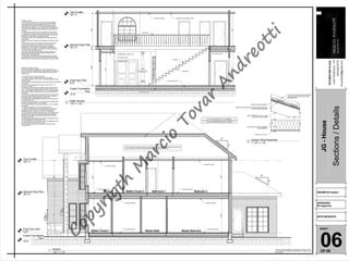
1. First Floor Plan
0'-0"
Second Floor Plan
10'-11"
Top of walls
19'-11"
Crawn Foundation
Plan
-2'-0"
NOTE: SECTIONS REFLECT A BASEMENT
FOUDATION. IF ANOTHER FOUDATION IS USED BUILDER
SHOULD DISREGARD FOUDATION SHOWN
Due to a variance of codes per region roof structure is not represented, please refer and comply with
all your local codes. Consult with local engineers for all structural requirements.
9"
12"
5"
12"
Floor joints as reqd.
Compound Ceiling
Compound Ceiling
Compound Ceiling
Floor joints as reqd.
Floor joints as reqd. Floor joints as reqd.
Compound Ceiling
9'-4"1'-7"9'-0"
8'-8"1'-7"9'-4"
GENERAL NOTES
1. All work shall be performed in accordance with all applicable
national, state and local codes, regulations, and FHA/VA MPS.
2. Contractor shall verify all conditions and dimensions at site
before begining construction. Any discrepancy shall be reported
to designer for justification and/or corretion before proceeding with
work. Contractors shall assume reponsability for errors that are no
reported.
3. All dimensions should be read or calculated and never scaled.
4. All footings to be below frost line (see local code) and must rest
on undisturbed soil capable of handling the building. Consult local
engenieer for proper footing and reinforcing sizes.
5. Contractor shall insure compatibility of the building with all site
requirements.
6. If backfill exceeds 4' against any foundation wall, reinforce as per
code.
7. All foundation and structural members should be verified and
stamped by an engineer in the state where construction is
occuring due to a wide variance in local codes, soil bearing
conditions, etc. The contractor is responsible for adjusting and
verifying all structural details and conditions to meet all codes and
to insure a quality and safe structure.
8. All wood, concrete and steel structural members shall be of a
good grade and quality and meet all national, state and local
building codes where applicable.
9. All columns or solid framing should be designed to carry loads
and should extend down thru the levels below and terminate at the
basement floor or at other bearing points designed to carry the load.
GENERAL FRAMING NOTES
The following notes are suggested minimum requeriments only.
Due to a variance of codes per region, please refer and comply with
all your local codes. Consult with local engineers for all structural
requirements.
1. Provide purlins at mid heigth of all walls.
2. All joists and rafters shall be aligned over studs below.
3. All headers shall be 2-2x10's with 1/2" plywood flitch plate unless
otherwise noted.
4. Framer have to install double floor joists under partition wall parallel to
joist direction.
5. Provide 1x4 cross bridging at mid point os span or 8'-0" O.C.
maximum in all floors.
6. All exterior corners (inside and outside corners) shall be braced
with 1/2" CDX plywood. Nailing schedule shall be 8d commons at
6" O.C. at all edges and 8d commons at 12" O.C. at all intermediate
studs (option - approved diagonal corner braces both directions at
all corners).
7. All columns or solid framing shall extend down thru all levels and
terminate at the basement floor and be supported by a thickened
slab, grade beam, or footing designed to carry load.
8. Provide double 2x8 strongback at md span for ceiling joists with
span greater than 10'-0".
9. Provide collar ties at upper 1/3 of vertical distsnce between ridge
board and ceiling joists at 4'-0" O.C maximum.
10. HIP, valley rafters and ridge boards shall be one "2x" size large
than rafters.
11. Roof decking shall be 1/2" CDX plywood minimum.
12. Where pre engineered floor and roof trusses are used, truss
manufacturer must provide shop drawings which bear seal of
registered engineer in state in wich work is to be performed.
13. All ceiling joists and rafter bracing to bear on load bearing walls
designed to carry load thru all levels and terminate at basement
floor and be supported by thickened slab grade beam or footing
designed to carry load.
14. All basement walls, beans and columns to be designed by local
structural engineer and meet all local codes.
15. All solid framing, columns, beams, etc., to be designed by local
structural engineer and meet all local codes.
16. All framed wall dimensions are based on 2x4 studs unless
otherwise noted.
Master BedroomMaster BathWalkin Closet 1
Bedroom 2Bathroom 1Walkin Closet 2Storage
9'-0"0'-11"10'-0"
First Floor Plan
0'-0"
Second Floor Plan
10'-11"
Top of walls
19'-11"
Crawn Foundation
Plan
-2'-0"
Stair string
Open Rail
19 raisers
Floor joints as reqd.
Floor joints as reqd.
Grade bean as reqd.
Floor joints as reqd.
Compound Ceiling.
Compound Ceiling.
Dropped beam as reqd. (TYP.)
Ceiling joists and rafters as reqd.
9'-4"1'-7"9'-0"
9'-1"
10'-0"0'-11"9'-0"
WOOD TRUSSES AT 24" O.C., SEE
STRUCTURAL DRAWINGS
1 LAYER 1/2" GYP. BD.
WOOD STRUCTURAL PANEL ROOF SHEATHING, SEE
STRUCTURAL DRAWINGS
BATT INSULATION PER THERMAL
REQUIREMENTS
ROOFING UNDERLAYMENT
TILE ROOF OR OTHER FINISH ROOFING -
CLASS A, B, OR C PER LOCAL CODE
REQUIREMENTS
SHEET:
1076MEETINGPLACE
CHATTANOOGA-TN
(423)432.8775
mt.andreotti@gmail.com
MARCIO TOVAR ANDREOTTI ASSUMES NO LIABILITY FOR
ANY CHANGES OR MODIFICATIONS MADE TO THESE PLANS
BY OTHERS
Sections/Details
JG-House
DRAWN BY:Author
APPROVED
BY:Approver
DATE:08/20/2015
OF:06
061/4" = 1'-0"
1
Section
1/4" = 1'-0"
2
Estair Section
1 1/2" = 1'-0"
3
Generic Roof Assembly
Copyrigth
M
arcio
Tovar
A
ndreotti