
Recommended
More Related Content
What's hot
What's hot (20)
Similar to Design of vibration isolation for vibratory compactors
Similar to Design of vibration isolation for vibratory compactors (20)
More from Manohar M Hegde
More from Manohar M Hegde (6)
Recently uploaded
Recently uploaded (20)
Design of vibration isolation for vibratory compactors
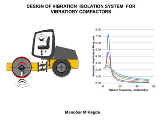
- 1. DESIGN OF VIBRATION ISOLATION SYSTEM FOR VIBRATIORY COMPACTORS Manohar M Hegde F f 0.00 1.00 2.00 3.00 4.00 5.00 6.00 7.00 8.00 0 20 40 60 ResultantAmplitudeofMass,mm Natural Frequency, Radians/Sec
- 2. DESIGN OF VIBRATION ISOLATION SYSTEM FOR VIBRATIORY COMPACTORS CONTENTS 1. Vibratory Compactors - Their Function, Types and Working Principle 2. Effect of Vibration on Operator (HAV and WBV) 3. Challenges in Designing a Suitable Vibration Control System 4. Vibration Mechanism and Principle of Isolation 5. Examples of Vibration Isolation Methods 6. Lumped Parameter Modeling 7. Considerations in Selecting Rubber Mounts 8. Steps in Selecting Rubber Mounts 9. Detailed Design Process Flow Chart 10.Analysis Examples of Lumped Mass Systems 11.Summary of Data Used and Results 12.Details of Typical Rubber Mounts 13.Notes
- 3. FUNCTION : Increasing The Density of Soil / Base Layer By Compacting In construction industry, loose soil needs to be densified so that it can take heavy loads without caving-in. Examples : Foundations of big buildings, laying of pipes In road building industry, the newly laid asphalt needs to be pressed down to ensure inter-particle adhesion and also to increase firmness of the road. Examples : Highway construction , laying asphalt on pavement DESIGN OF VIBRATION ISOLATION SYSTEM FOR VIBRATIORY COMPACTORS
- 4. Types of Vibratory Compactors Plate Drum- Drum Wheel- Drum DESIGN OF VIBRATION ISOLATION SYSTEM FOR VIBRATIORY COMPACTORS
- 5. Principle of Compaction For Shallow DepthFor Moderate DepthFor Deeper Layers Effect of Compaction on Soil Normal Soil Compacted Soil DESIGN OF VIBRATION ISOLATION SYSTEM FOR VIBRATIORY COMPACTORS Water Air
- 6. Importance of Vibration Control WBV – Whole Body Vibration Max limit 0.5 m/sec2 HAV - Hand Arm Vibration Max limit 2.5 m/sec2 “ Magnitude of force F may vary from 9kN (Plate Compactor) to 350kN (27 ton Drum -Wheel Compactor ) “ F “Maximum Levels of Vibration Felt By The Operator Should Conform to Occupational Safety Standards” f F f DESIGN OF VIBRATION ISOLATION SYSTEM FOR VIBRATIORY COMPACTORS ISO 2631, ISO 5349, BS 6841, VDI 2057, EN2002/44/EC ………..
- 7. Challenges Faced While Designing a Vibration Control system 2. System Analysis (Lumped Mass-Stiffness) and Math Modeling 1. Choosing a Simple and Effective System 3. Collection of Appropriate Data 5. Design Verification And Validation DESIGN OF VIBRATION ISOLATION SYSTEM FOR VIBRATIORY COMPACTORS 4. Handling Complex Calculations
- 8. Vibration Mechanism and Vibration Isolation Plate Compactor Drum Compactor F X Z Vibrating Plate X Y Machine Frame Isolation Mounts Handle Z Y Vibrating Drum Operator’s seat Chassis Isolation Mounts DESIGN OF VIBRATION ISOLATION SYSTEM FOR VIBRATIORY COMPACTORS
- 9. Isolation in Single Stage Drum Compactor X Y Y Stage-1 Plate Compactor F X Y Y Stage-1 DESIGN OF VIBRATION ISOLATION SYSTEM FOR VIBRATIORY COMPACTORS
- 10. Isolation in Multiple Stages Plate Compactor F X Z Y Stage-1 Stage-2 Drum Compactor X Z Y Stage-1 Stage-3 Stage- 2 DESIGN OF VIBRATION ISOLATION SYSTEM FOR VIBRATIORY COMPACTORS
- 11. Plate Compactor Example of Using Vibration Isolation DESIGN OF VIBRATION ISOLATION SYSTEM FOR VIBRATIORY COMPACTORS Rubber Mount
- 12. Drum-Drum Compactor DESIGN OF VIBRATION ISOLATION SYSTEM FOR VIBRATIORY COMPACTORS Example of Using Vibration Isolation Rubber Mount Rubber Mount
- 13. Drum-Wheel Compactor DESIGN OF VIBRATION ISOLATION SYSTEM FOR VIBRATIORY COMPACTORS Example of Using Vibration Isolation Rubber Mount Rubber Mount
- 14. Lumped Parameter Modeling Objective Function - Value of Resultant Vibration at Operators Hand /Seat Design Parameters Considered - Mass, Spring Stiffness, Damping Controlling Parameter – Natural Frequency of the System Analysis Approach - Lumped Parameters and Math Modeling Y X ’ Vibrating Drum Operator’s seat Chassis Isolation Mounts F MP Mc Chassis Drum c K Ground ↕X=X0 Sinωt ↕ Y(t) K Ms c K ↕ Z(t) Handle / Seat Module Isolation Mounts Ground Reaction 0.00 1.00 2.00 3.00 4.00 5.00 6.00 7.00 8.00 0 20 40 60 ResultantAmplitudeofMass,mm Natural Frequency, Radians/Sec Amplitude Vs Frequency DESIGN OF VIBRATION ISOLATION SYSTEM FOR VIBRATIORY COMPACTORS
- 15. Considerations in Selecting a Rubber Mount Load Capacity of The Mount. Stiffness K of The Mount. Type, Size and Mounting Method. Ease of Assembly and Dis-assembly. DESIGN OF VIBRATION ISOLATION SYSTEM FOR VIBRATIORY COMPACTORS
- 16. Steps in Selecting Rubber Mounts 1. Design a Lumped Mass - Stiffness System ; Set Isolation Targets. 2. Determine by Iteration Values of Required Stagewise Stiffnesses. 3. Select Rubber Mounts Meeting The Minimum Load Criteria and Stiffness Values. 4. Use The Stiffness Values of The Selected Mounts To Verify Calculations. 5. Adapt The Selected Mounts in The Compactor Design. DESIGN OF VIBRATION ISOLATION SYSTEM FOR VIBRATIORY COMPACTORS
- 17. Vibration Isolation System Design Process Flow Chart Set-up Isolation Model Estimate Values of the Lumped Parameters Set a Target Value for Isolation Derive Math Expression For Isolation Decide by Iteration Required Stagewise Stiffnesses Decide the no. of Mounts at Each Stage Calculate the Static Deflection of Each Mount Short list Mount Suppliers; Collect Catalogues Select Mounts Meeting Deflection and Size Criteria Adapt The Selected Mounts in Detail Design Use K Values in Calculation ;Check if Isolation is Achieved Obtain Stiffness Value K For Identified Mounts Iteration DESIGN OF VIBRATION ISOLATION SYSTEM FOR VIBRATIORY COMPACTORS
- 18. Example –1 ; Plate Compactor ; Single Stage Isolation Total Machine Weight, MM – 96 Kgs Weight of The Chassis Including Handle, Mc – 40 Kgs Stiffness of Stage -1 Isolation, K1 – 800 N/mm F X Y Y Stage-1 Amplitude, mm – 1.7 mm Frequency, - 75 Hz (471 rad/sec) Centrifugal Force, F0 – 16 kN DESIGN OF VIBRATION ISOLATION SYSTEM FOR VIBRATIORY COMPACTORS
- 19. Mathematical model – SDOF with Forced Vibration Plate / Drum MM =40 Kgs Total Chassis Weight Lumped c K=800N/mm Ground ↕X=X0 Sinωt ↕ Y0, Y(t) ↕ F(t) Motion Transmissibility = Y0/X0 Example –1 ; Plate Compactor ; Single Stage Isolation Resultant Vibration Level at Handle bar: 2.3 m/sec2 DESIGN OF VIBRATION ISOLATION SYSTEM FOR VIBRATIORY COMPACTORS
- 20. Example –1 ; Plate Compactor ; 2 - Stage Isolation Total Machine Weight, MM – 96 Kgs Weight of The Chassis, Mc – 35 Kgs Weight of The Handle, Ms - 5 Kgs Stiffness of Stage-1 Isolation, K1 – 800 N/mm Stiffness of Stage- 2 Isolation, K2 – 400 N/mm F X Z Y ’ Stage-1 Stage-2 Amplitude,mm – 1.7 mm Frequency, - 75 Hz (471 rad/sec) Centrifugal Force, F0 – 16 kN DESIGN OF VIBRATION ISOLATION SYSTEM FOR VIBRATIORY COMPACTORS
- 21. Plate / Drum Mc K1 Ground ↕X=X0 Sinωt ↕ Y0, Y(t) ↕ F(t) K2 Ms ↕ Z0, Z(t) Chassis Handle Module Motion Transmissibility = Z0/X0 Resultant Vibration Level at Handle bar: 1.3 x10⁻⁵ m/Sec2 Example –1 ; Plate Compactor ; 2 stage Isolation DESIGN OF VIBRATION ISOLATION SYSTEM FOR VIBRATIORY COMPACTORS Mathematical model – 2 DOF with Forced Vibration
- 22. Example –2 ; Drum Compactor Single Stage Isolation Total Machine Weight, MM – 20000 Kgs Weight of The Chassis Including Operator’s Platform, Mc – 2500 Kgs Stiffness of Stage-1 Isolation, K1 – 12000 N/mm Amplitude, mm – 2.1 mm Frequency, - 28 Hz (176 rad/sec) Centrifugal Force, F0 – 330 kN Drum Compactor X Y Y Stage-1 DESIGN OF VIBRATION ISOLATION SYSTEM FOR VIBRATIORY COMPACTORS
- 23. Mathematical model – SDOF with Forced Vibration Plate / Drum MM =2500 Kgs Total Chassis Weight Lumped c K=330kN Ground ↕X=X0 Sinωt ↕ Y0, Y(t) ↕ F(t) Motion Transmissibility = Y0/X0 Example –2 ; Drum Compactor ; Single Stage Isolation Resultant Vibration Level : 0.47 m/Sec2 DESIGN OF VIBRATION ISOLATION SYSTEM FOR VIBRATIORY COMPACTORS
- 24. Total Machine Weight, MM – 20200 Kgs Weight of The Chassis, Mc – 2000 Kgs Weight of The Operators Platform, Ms -500 Kgs Stiffness Stage-1 Isolation, K1 – 12000 N/mm Stiffness Stage- 2 Isolation, K2 – 8000 N/mm Amplitude,mm – 2.1 mm Frequency, - 28 Hz (176 rad/sec) Centrifugal Force, F0 – 330 kN Example –2 ; Drum Compactor ; 2 Stage Isolation Drum Compactor X Z Y Stage-1 Stage-2 DESIGN OF VIBRATION ISOLATION SYSTEM FOR VIBRATIORY COMPACTORS
- 25. Plate / Drum Mc K1 Ground ↕X=X0 Sinωt ↕ Y0, Y(t) ↕ F(t) K2 Ms ↕ Z0, Z(t) Chassis Seat Module Motion Transmissibility = Z0/X0 Resultant Vibration Level : 6 x10⁻⁶ m/Sec2 Example –2 ; Drum Compactor ; 2 Stage Isolation DESIGN OF VIBRATION ISOLATION SYSTEM FOR VIBRATIORY COMPACTORS Mathematical model – 2 DOF with Forced Vibration
- 26. SUMMARY OF DATA Sl No Machine Data For 1-Stage Isolation Data For 2-Stage Isolation 1 Plate Compactor Mtotal=96 Kgs CF=16 kN X0= 1.7mm Mc =40 Kgs K1= 800 N/m2 Mc=35 Kgs K1=800 N/m2 Ms=5 Kgs K2=400 N/m2 2 Drum Compactor Mtotal=20000 Kgs CF=330 kN X0=2.1 mm Mc =2500 Kgs K1 =12000 N/m2 Mc =2000 Kgs K1 =12000 N/m2 Ms=500 Kgs K2=8000 N/m2 DESIGN OF VIBRATION ISOLATION SYSTEM FOR VIBRATIORY COMPACTORS
- 27. SUMMARY OF RESULTS Sl No Machine Maximum allowed Vibration Level Vibration Level with 1- Stage Isolation Vibration Level with 2- Stage Isolation 1 Plate Compactor 2.5 m/sec2 2.3 m/sec2 1.3 x 10⁻⁵ m/sec2 2 Drum Compactor 0.5 m/sec2 0.47 m/sec2 6 x 10⁻⁶ m/sec2 DESIGN OF VIBRATION ISOLATION SYSTEM FOR VIBRATIORY COMPACTORS
- 28. Some Typical Rubber Mounts Compression-Shear Mount Shear Mount Shear MountBush DESIGN OF VIBRATION ISOLATION SYSTEM FOR VIBRATIORY COMPACTORS
- 29. NOTES 1. Use Simplified Math Models,To Begin With. 2. Lumped Parameters With 2-Stage Reduction is Preferable. 3. Effect of Damping in Rubber Mount Can Be Ignored. 4. Collect Equipment Related Data by Benchmarking. 5. Verify Calculations Using Measured Values on Benchmarked Equipment. 6. Use Combination of Shear and Compressive Modes, if Necessary, While Using The Rubber Mounts. 7. Real Problem is More Complex ; Requires Much Mathematical Effort. 8. Progressively Develop More Complex Math Models and Refine Calculations. 9. Use Simulation With Specialised Software Packages to Account For Distributed Nature Of Mass and Stiffness. 10.Include Ground Resistance in The Form of Stiffness Value in The Calculation, if Accurate Data is Available. DESIGN OF VIBRATION ISOLATION SYSTEM FOR VIBRATIORY COMPACTORS