
Recommended
More Related Content
What's hot
What's hot (20)
Similar to Steel and Cast Iron Fabrication Processes
Similar to Steel and Cast Iron Fabrication Processes (20)
More from Manish Nepal
More from Manish Nepal (15)
Recently uploaded
Recently uploaded (20)
Steel and Cast Iron Fabrication Processes
- 1. 1 Chapter 11 - 1 Steel and cast iron Chapter 11 - 2
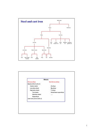
- 2. 2 Chapter 11 - 3 Adapted from Fig. 11.1, Callister 7e. Taxonomy of Metals Metal Alloys Steels Ferrous Nonferrous Cast Irons Cu Al Mg Ti <1.4wt%C 3-4.5wt%C Steels <1.4wt%C Cast Irons 3-4.5wt%C Fe3C cementite 1600 1400 1200 1000 800 600 400 0 1 2 3 4 5 6 6.7 L g austenite g+L g+Fe3C a ferrite a+Fe3C a+g L+Fe3C d (Fe) Co , wt% C Eutectic: Eutectoid: 0.76 4.30 727°C 1148°C T(°C) microstructure: ferrite, graphite cementite Chapter 11 - 4 1. Other terms: plain steel, mild steel, low-carbon steel 2. Available in almost all product forms: e.g. sheet, strip, bar, plate, tube, pipe etc. 3. Designation: e.g. 1040 steel - 0.40 wt% C 4. Up to 2 wt% C 5. Limitation for other alloying elements: Si up to 0.6 %, Cu up to 0.6 % Mn up to 1.65 % Carbon steel
- 3. 3 Chapter 11 - 5 Chapter 11 - 6 t11_01b_pg361 Hot-rolled steels and typical applications
- 4. 4 Chapter 11 - 7 AISI: the American Iron and Steel Institute SAE: the Sociaty of Automotive and Engineering ASTM: the American Society for Testing and Materials UNS: the Uniform Numbering System Chapter 11 - 8 High alloys:
- 5. 5 Chapter 11 - 9 Chapter 11 -10 Designations, compositions and applications for six tool steels
- 6. 6 Chapter 11 -11 Chapter 11 -12
- 7. 7 Chapter 11 -13 Chapter 11 -14
- 8. 8 Chapter 11 -15 Stainless steels 1. More resistant to rusting and staining than carbon- and low-alloy steels 2. Chromium addition, usually above 10 wt% (4-30%) Chapter 11 -16 Stainless steels
- 9. 9 Chapter 11 -17 Chapter 11 -18
- 10. 10 Chapter 11 -19 Based on data provided in Tables 11.1(b), 11.2(b), 11.3, and 11.4, Callister 7e. Steels Low Alloy High Alloy low carbon <0.25wt%C Med carbon 0.25-0.6wt%C high carbon 0.6-1.4wt%C Uses auto struc. sheet bridges towers press. vessels crank shafts bolts hammers blades pistons gears wear applic. wear applic. drills saws dies high T applic. turbines furnaces V. corros. resistant Example 1010 4310 1040 4340 1095 4190 304 Additions none Cr,V Ni, Mo none Cr, Ni Mo none Cr, V, Mo, W Cr, Ni, Mo plain HSLA plain heat treatable plain tool austenitic stainless Name Hardenability 0 + + ++ ++ +++ 0 TS - 0 + ++ + ++ 0 EL + + 0 - - -- ++ increasing strength, cost, decreasing ductility Chapter 11 -20 Ferrous Alloys Iron containing – Steels - cast irons Nomenclature AISI & SAE 10xx Plain Carbon Steels 11xx Plain Carbon Steels (resulfurized for machinability) 15xx Mn (10 ~ 20%) 40xx Mo (0.20 ~ 0.30%) 43xx Ni (1.65 - 2.00%), Cr (0.4 - 0.90%), Mo (0.2 - 0.3%) 44xx Mo (0.5%) where xx is wt% C x 100 example: 1060 steel – plain carbon steel with 0.60 wt% C Stainless Steel -- >11% Cr
- 11. 11 Chapter 11 -21 Cast Iron • Ferrous alloys with > 2.1 wt% C – more commonly 3 - 4.5 wt%C • low melting (also brittle) so easiest to cast • Cementite decomposes to ferrite + graphite Fe3C 3 Fe (a) + C (graphite) – cementite (Fe3C) a metastable phase – graphite formation promoted by • Si > 1 wt% • slow cooling Chapter 11 -22 Fe-C True Equilibrium Diagram Graphite formation promoted by • Si > 1 wt% • slow cooling 1600 1400 1200 1000 800 600 400 0 1 2 3 4 90 L g+L a + Graphite Liquid + Graphite (Fe) Co, wt% C 0.65 740°C T(°C) g+ Graphite 100 1153°Cg Austenite 4.2 wt% C a + g Cast iron 1. Gray iron 2. Nodular (ductile) iron 3. White iron 4. Malleable iron 5. Compacted graphite iron (CGI)
- 12. 12 Chapter 11 -23 Types of Cast Iron Gray iron – 1 - 3 % Si, 2.5 – 4% C – graphite flakes plus ferrite/pearlite – brittleness due to the flake-like graphite • weak & brittle under tension • stronger under compression • excellent vibrational dampening • wear resistant Ductile (nodular) iron – a small amount (0.05 wt%) of Mg or Ce – spheroidal graphite precipitates (nodules) rather than flakes – matrix often pearlite or ferrite – Ductility increased by a factor of 20, strength is doubled Chapter 11 -24 Optical micrograph of a grey iron (Fe-3.3C-2.1Si-0.5Cr- 0.5Mo-1.0Cu) Microstructure of pearlite in the grey iron (Fe-3.3C-2.1Si- 0.5Cr-0.5Mo-1.0Cu). TEM.
- 13. 13 Chapter 11 -25 (a) steel; (b) grey cast iron Chapter 11 -26 Types of Cast Iron White iron – <1wt% Si, harder but brittle – eutectic carbide plus pearlite – large amount of Fe3C formed during casting Malleable iron – the result of annealing white iron castings, 800º-900º C – cementite→ graphite precipitates, clusters or rosettes – more ductile
- 14. 14 Chapter 11 -27 Types of Cast Iron Compacted graphite iron (CGI) 1. C: 3.1-4.0%, Si: 1.7-3.0% 2. Lower content of Mg or Ce 3. Worm-like (vermicular) graphite particles • higher thermal conductivity • better resistance to thermal shock • lower oxidation at elevated temperature Chapter 11 -28 Production of Cast Iron Adapted from Fig.11.5, Callister 7e.
- 15. 15 Chapter 11 -29 Cast iron Chapter 11 -30 Which type of cast iron is in the pictures illustrated below ?
- 16. 16 Chapter 11 -31 Limitations of Ferrous Alloys 1) Relatively high density 2) Relatively low conductivity 3) Poor corrosion resistance Chapter 11 -32 Metal Fabrication • How do we fabricate metals? – Blacksmith - hammer (forged) – Molding - cast • Forming Operations – Rough stock formed to final shape Hot working vs. Cold working • T high enough for • well below Tm recrystallization • work hardening • Larger deformations • smaller deformations
- 17. 17 Chapter 11 -33 FORMING roll Ao Ad roll • Rolling (Hot or Cold Rolling) (I-beams, rails, sheet & plate) Ao Ad force die blank force • Forging (Hammering; Stamping) (wrenches, crankshafts) often at elev. T Adapted from Fig. 11.8, Callister 7e. Metal Fabrication Methods - I ram billet container container force die holder die Ao Adextrusion • Extrusion (rods, tubing) ductile metals, e.g. Cu, Al (hot) tensile force Ao Addie die • Drawing (rods, wire, tubing) die must be well lubricated & clean CASTING JOINING Chapter 11 -34 FORMING CASTING JOINING Metal Fabrication Methods - II • Casting- mold is filled with metal – metal melted in furnace, perhaps alloying elements added. Then cast in a mold – most common, cheapest method – gives good production of shapes – weaker products, internal defects – good option for brittle materials
- 18. 18 Chapter 11 -35 • Sand Casting (large parts, e.g., auto engine blocks) Metal Fabrication Methods - II • trying to hold something that is hot • what will withstand >1600ºC? • cheap - easy to mold => sand!!! • pack sand around form (pattern) of desired shape Sand Sand molten metal FORMING CASTING JOINING Chapter 11 -36 plaster die formed around wax prototype • Sand Casting (large parts, e.g., auto engine blocks) • Investment Casting (low volume, complex shapes e.g., jewelry, turbine blades) Metal Fabrication Methods - II Investment Casting • pattern is made from paraffin. • mold made by encasing in plaster of paris • melt the wax & the hollow mold is left • pour in metal wax FORMING CASTING JOINING Sand Sand molten metal
- 19. 19 Chapter 11 -37 plaster die formed around wax prototype • Sand Casting (large parts, e.g., auto engine blocks) • Investment Casting (low volume, complex shapes e.g., jewelry, turbine blades) Metal Fabrication Methods - II wax • Die Casting (high volume, low T alloys) • Continuous Casting (simple slab shapes) molten solidified FORMING CASTING JOINING Sand Sand molten metal Chapter 11 -38 CASTING JOINING Metal Fabrication Methods - III • Powder Metallurgy (materials w/low ductility) pressure heat point contact at low T densification by diffusion at higher T area contact densify • Welding (when one large part is impractical) • Heat affected zone: (region in which the microstructure has been changed). Adapted from Fig. 11.9, Callister 7e. (Fig. 11.9 from Iron Castings Handbook, C.F. Walton and T.J. Opar (Ed.), 1981.) piece 1 piece 2 fused base metal filler metal (melted) base metal (melted) unaffectedunaffected heat affected zone FORMING
- 20. 20 Chapter 11 -39 Annealing: Heat to Tanneal, then cool slowly. Based on discussion in Section 11.7, Callister 7e. Thermal Processing of Metals Types of Annealing • Process Anneal: Negate effect of cold working by (recovery/ recrystallization) • Stress Relief: Reduce stress caused by: -plastic deformation -nonuniform cooling -phase transform. • Normalize (steels): Deform steel with large grains, then normalize to make grains small. • Full Anneal (steels): Make soft steels for good forming by heating to get g, then cool in furnace to get coarse P. • Spheroidize (steels): Make very soft steels for good machining. Heat just below TE & hold for 15-25h. Chapter 11 -40 a) Annealing b) Quenching Heat Treatments c) c) Tempered Martensite Adapted from Fig. 10.22, Callister 7e. time (s) 10 10 3 10 5 10 -1 400 600 800 T(°C) Austenite (stable) 200 P B TE 0% 100% 50% A A M + A M + A 0% 50% 90% a)b)
- 21. 21 Chapter 11 -41 f11_10_pg389 Chapter 11 -42
- 22. 22 Chapter 11 -43 Hardenability--Steels • Ability to form martensite • Jominy end quench test to measure hardenability. • Hardness versus distance from the quenched end. Adapted from Fig. 11.11, Callister 7e. (Fig. 11.11 adapted from A.G. Guy, Essentials of Materials Science, McGraw-Hill Book Company, New York, 1978.) Adapted from Fig. 11.12, Callister 7e. 24°C water specimen (heated to g phase field) flat ground Rockwell C hardness tests Hardness,HRC Distance from quenched end Chapter 11 -44 • The cooling rate varies with position. Adapted from Fig. 11.13, Callister 7e. (Fig. 11.13 adapted from H. Boyer (Ed.) Atlas of Isothermal Transformation and Cooling Transformation Diagrams, American Society for Metals, 1977, p. 376.) Why Hardness Changes With Position distance from quenched end (in) Hardness,HRC 20 40 60 0 1 2 3 600 400 200 A fi M A fi P 0.1 1 10 100 1000 T(°C) M(start) Time (s) 0 0% 100% M(finish) M artensite M artensite + Pearlite Fine Pearlite Pearlite
- 23. 23 Chapter 11 -45 Hardenability vs Alloy Composition • Jominy end quench results, C = 0.4 wt% C (table 11.2a p363) • "Alloy Steels" (4140, 4340, 5140, 8640) --contain Ni, Cr, Mo (0.2 to 2wt%) --these elements shift the "nose". --martensite is easier to form. Adapted from Fig. 11.14, Callister 7e. (Fig. 11.14 adapted from figure furnished courtesy Republic Steel Corporation.) Cooling rate (°C/s) Hardness,HRC 20 40 60 100 20 30 40 50 Distance from quenched end (mm) 210100 3 4140 8640 5140 1040 50 80 100 %M4340 T(°C) 10 -1 10 10 3 10 50 200 400 600 800 Time (s) M(start) M(90%) shift from A to B due to alloying BA TE Chapter 11 -46 • Effect of quenching medium: Medium air oil water Severity of Quench low moderate high Hardness low moderate high • Effect of geometry: When surface-to-volume ratio increases: --cooling rate increases --hardness increases Position center surface Cooling rate low high Hardness low high Quenching Medium & Geometry
- 24. 24 Chapter 11 -47 • Steels: increase TS, Hardness (and cost) by adding --C (low alloy steels) --Cr, V, Ni, Mo, W (high alloy steels) --ductility usually decreases with additions. • Non-ferrous: --Cu, Al, Ti, Mg, Refractory, and noble metals. • Fabrication techniques: --forming, casting, joining. • Hardenability --increases with alloy content. • Precipitation hardening --effective means to increase strength in Al, Cu, and Mg alloys. Summary