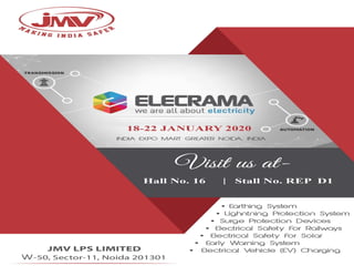
Plz Join us in Invitation Elecrama exhibition (18 22 jan2020 and new product display information

Dear Sir Wish you a very Happy New Year 2020 We wish to inform you our Customer that we are Participating in Exhibition Date 18th-22nd Jan 2020 Place Expo Center Greater Noida (U.P.) Plz Click Ling for Registration https://lnkd.in/fQjVx8c Easy Way to Visit by Metro Rail , Shuttle Service , and use of CAB. Our Stall in Hall #16 Stall # REP D1 JMV LPS Ltd Always think in direction to offer maximum products in Make in India to the Industries and Follow the Norms set by our Govt Like NBC 2016 , OSID, RDSO,CEA and many more as per Industrial Standards National and International. Our Main AIM to Offer Product with Technology use for Electrical Installation Safety of Human Lives as per NBC2016 ,IEC and IEEE. We are in position to answer any queries Related to Earthing as Per IS3043, Grid Earthing as per IEEE80 and Surge and Lightning Protection as per IEC62305. We are using CDEGS Software for Grid Design and Lightning Protection as Per IEC62305 now in more challenge when Building Segment started adopting Structural Earthing and Down Conductor for LIghtning Through Colom. We have established First Lab is India for Testing for Lighting and Surge up to 200KA , and High Voltage 550KV as per IEC Norms. you will find many more once you visit our stall . Plz Book your pass online and Print Copy to Avoid Que

Recommended
Recommended
More Related Content
What's hot
What's hot (19)
Similar to Plz Join us in Invitation Elecrama exhibition (18 22 jan2020 and new product display information
Similar to Plz Join us in Invitation Elecrama exhibition (18 22 jan2020 and new product display information (20)
More from Mahesh Chandra Manav
More from Mahesh Chandra Manav (20)
Recently uploaded
Recently uploaded (20)
Plz Join us in Invitation Elecrama exhibition (18 22 jan2020 and new product display information
- 2. Be-Ware I am Electricity Not a Toy Follow Electrical Safety
- 4. Earthing and Design Guide Earth Resistance Earth resistance depends on following factors (a) Type of earth soil (b) Temperature of earth (c) Humidity in earth (d) Minerals in earth (e) Length of electrode in the earth (f) Electrode shape and size (g) Distance between two electrodes (h) Number of electrodes 2. Maximum earth resistance allowed is as follows Major power station — 0.5 ohms (b) Major Sub-stations — 1.0 ohms (c) Minor Sub-station — 2 ohms (d) Neutral Bushing — 2 ohms (e) Service connection — 4 ohms (f) L.T Lightning Arrestor — 4 ohms (g) L.T. Pole — 5 ohms (h) H.T. Pole — 10 ohms (i) Tower — 20-30 ohms
- 5. Utilize your Power Precisely for EV
- 6. Risk Assessment as per IS/IEC 62305 Lightning Risk Assessme nt Software
- 7. Lightning Protection System Design as per IS/IEC 62305 An external LPS consists of: 1. Air- Terminationsystem to intercept a lightning flash to the structure 2. Down- conductorto conducts the lightning current safely towards earth 3. Earth-termination system to disperse the lightningcurrent intothe earth
- 9. Surge Monitoring Device 1 2 1. Surge Counter – For continuous monitoring and counting of surges/ spikes. 2. Surge Analyzer – Offering real time check and registering upto 0-255 of lightning strikes.
- 10. We have build INDIA’S 1ST RESEARCH CENTRE for Lightning Protection System Components & Surge Protection Devices with the Lightning Voltage Impulse Test capacity 550KV & Current Impulse generator capacity of 200 KA.
- 11. In House Testing Facility We are having entire testing facility of Earthing SystemComponents as per mentioned details: 1. Testing of Copper Bonded Rods as per UL 467, IEC 62561-2 2. Testing of Earth Enhancement Compound as per IEC 62561-7 3. Testing of Exothermic Welding System as per IEEE
- 13. Make in India Organization Foundation laid in 2003, JMV LPS Limited set itself as the pioneer technology leader & service provider that offers reliable protection of people, buildings, electrical and electronic devices and systems against the effects of lightning, surges and fault current.Thanks to our expertise dedication and pioneering spirit we have been pushing developments in each and every industry segment since more than a decade. JMV is equipped with great technology advancement with state-of-the-art facilities, customer centric approach and continuous process optimization.These facilities inspiring us to produce world class products and making us the leading manufacturers in the country. The hunger of continuous development and technology upgradation is a key behind our growth & development.We have a great strength of dedicated engineers contributing in research, development, innovation & creation. SMART CITIES AIR NAVAL & ARMY BUILDING & INFRA POWER TRANSMISSION & DISTRIBUTION SIGNALLING & TELECOM OIL & GAS SOLAR & HESBS TUNNEL EV INTEGRATED ROAD TRANSPORT SYSTEM RAILWAYS & METRO RAIL
- 15. Maintenance Free Earthing System As Per IS 3043:2018, NBC:2016, IEEE 80:2013, IEC 62561 Series External Lightning Protection System As Per NBC:2016, IS/IEC 62305:2010, IEC 62561 Series, NF C 17-102:2011 Solar Protection As Per IEC 61439-1,2,3,4,5,6, IEC 62852, IEC 60296 Exothermic Welding System As Per NBC:2016, IEEE 80:2013, IEEE 837:2014 Surge Protection Devices ( Internal Lightning Protection System ) As Per NBC:2016, IS/IEC 62305:2010, IEC 61643:2011
- 16. Maintenance Free Earthing System A well-designed earthing system is the primary line of protection for any electrical/electronic installation from destructive fault current.The grounding/earthing system offers a low impedance path to the fault current resulting into the safety of personnel and equipment. As per IEEE 80:2013, “A safe grounding design has the following two objectives: - To provide means to carry electric currents into the earth under normal and fault conditions without exceeding any operating and equipment limits or adversely affecting continuity of service. - To reduce the risk of a person in the vicinity of grounded facilities being exposed to the danger of critical electric shock.” Maintenance Free Earthing System with Exothermically Welded Bus Bar Maintenance Free Earthing System with Clamp Connection EARTH MAT DESIGN 05
- 17. TECHNICAL FEATURES This solid rod technology offers excellent product life of +40 years. Solution offers remarkable electrical conductivity & high tensile strength. Excellent fault current carrying capacity contrasted with most metals. Exhibits corrosion resistant properties as copper. The technology can withstand more mechanical abuses comparatively. The standard dimensions – 14.2mm dia,17.2mm dia,19mm dia,23.2mm dia,25mm dia & 38mm dia with standard length of 3 to 9 meters. *The dimension of the rod can be customised as per the fault current requirement. * Higher sizes are available on request. Copper Bonded Steel Rods: Complying IS 3043, NBC 2016, IEC 62561-2, IEEE 80, UL 467, BS 7430 Copper Bonded Steel Rods are most appreciable and highly preferrable product known for its ultimate performance with significance of no hidden factor.These low carbon,molecularly bonded mild steel rods are manufactured, inheriting 99.99% pure electrolytic copper coating of minimum 250 microns.This combination contribute to the high tensile strength and remarkable conductivity of the whole system. Based on solid rod technology, copper bonded rods are electrically and mechanically robust solution complying national & international standards. Each rod can be visually inspected to meet the requirements of IEC 62561-2.This solution is recommended in almost every soil condition because copper on outer surface of the rod will not slip or tear, when driven inside the earth nor the rod will suffer peeling or any kind of crack when it gets bent. CBR 1412 MODELS FAULT CARRYING CAPACITY 15kA CBR 1730 25kA CBR 1430 19kA CBR 2330 50kA CBR 3830 50kA 06
- 18. The National Electrical Grounding Research Project (NEGRP) was a project conducted by the National Fire Protection Association (NFPA) Research Foundation.The objective of the project was to compare the long-term performance of different types of earthing rods. According to the project, several different types of earthing rods were buried in different types of soils.After 10 years in the year 2003, one of the original sites (Pawnee) was excavated and the rods were removed.It was found that the copper bonded rod was virtually free of corrosion while the galvanised rod showed significant deterioration.The UL listed copper bonded ground rods have served the industry exceptionally well, providing a 40+ year life, typically 4 times that of galvanised ground rods. NEGRP- REAL TIME RESEARCH ON GI ROD AND COPPER BONDED ROD LATEST CODES REFERENCES NBC : 2016 Clause no. 83, Page 63: It is recommended to use either copper /stainless steel or copper coated steel electrode. IEEE 80 : 2013 Clause no 11.2.2, Page 40: Copper Clad Steel is usually used for underground rods and occassionallyforgrounding grids, especially where theft is a problem. IS 3043 : 2018 Clause no. 14.2.2, Page 25: Copper clad mild steel rods can be used in place of normal mild steel rod where the soil is corrosive. 07
- 19. As per IS 3043:2018 & IEEE 80:2013, “It is often impossible to achieve the desired reduction in ground resistance by adding more grid conductors or ground rods. An alternate solution is to effectively increase the diameter of the electrode by modifying the soil surrounding the electrode.The inner shell of soil closest to the electrode normally comprises the bulk of the electrode ground resistance to remote earth.” Premium-Quality, Carbon based high-grade Ground Enhancing Material with a resistivity of less than 0.12 Ω-m to be used with Maintenance Free Earthing System so as to achieve lower ohmic value in soil of high resistivity. JAM LITE is a fine blend of corrosion free and highly conductive minerals that absorbs quite much huge amount of water. It is a permanent enhancement material and will not leach any chemicals into the ground. RoHS compliant ground enhancement material is a first-rate conductive material,made recognition for its effectiveness, durability and non-hazardous characteristics. Earth Enhancement Compound is intended to use with earthing system in order to lower down ground resistance value in order to improve the conductivity of soil.The product is NABL accredited and precisely developed as per IEC 62561-7.This maintenance-free compact solution can be easily settled in areas with poor soil conditions (say rocky, sandy or desert soil) without violating any environmental regulations. It is available in bags of Kilograms. Earth Enhancement Compound: Complying IS 3043, NBC 2016, IEEE 80, IEC 62561-7 JAM LITE It is an innovative,eco-friendly and precisely developed backfill earthing compound that eliminates the need of salt & charcoal to improve earthing system’s conductivity. This specially designed moisture boosting earthing compound is reckoned for high end qualities like non corrosive, highly conductive, moisture absorbing and retaining feature for a long period of time. It is readily available in packing of 25 kg Bag. JAM FILL 08
- 20. Conductivity Testing of Compound Using Continuity Tester TECHNICAL FEATURES No regular maintenance is required. The material is eco-friendly and chemically inert to subsoil. Low resistive compound with resistivity of less than 0.12 ohm-mtr. ROHS tested compound tested by NABL accredited lab in compliance to IEC 62561-7. The material shall be tested for leaching test, corrosion test, sulfur test and resistivity test as per IEC62561-7. It shall be carbon based material and shall be free from bentonite and other hazardous substances. Stabilized in terms of physical and chemical property. It shall be free from corrosion. The product does not dissolve, deteriorate or leach out with time. It shall have high conductivity, improves earth’s absorbing power and humidity retention capability. LATEST CODES REFERENCES NBC : 2016 Clause no. 8.4.2, Page 63 & 67:To reduce the soil resistivity, artificial soil treatment shall be adopted.The material of the earthing enhancing compound shall be chemically inert to subsoil. It shall not pollute the environment. It shall provide a stable environment in terms of physical and chemical properties and exhibit low resistivity. The compound shall not be corrosive to the earth electrodes. IEEE 80 : 2013 Clause no 14.5, Page 68: Ground enhancement materials, some with a resistivity of less than 0.12 ohm-mtr (about 5% of the resistivity of bentonite), are typically placed around the rod in an augured hole or around grounding conductors in a trench, in either a dry form or premixed in a slurry. IS 3043 : 2018 Clause no 13.8, Page 23: Ground enhancement materials, some with a resistivity of less than 0.12 ohm-mtr (about 5% of the resistivity of bentonite), are typically placed around the rod in an augured hole or around grounding conductors in a trench, in either a dry form or premixed in a slurry. 09
- 21. It is generally said to specify entire system as trouble-free each element stick to it should exceed the dilemma of unforeseen risks.To achieve complete, economical and compact earthing solution right from copper bonded rods, earth enhancement compound and other fundamental accessories, we have copper clad steel conductor to adjoin the system. Molecularly bonded copper clad steel conductor employ 99.99% steel core with pure copper coating so as to acquire spectacular flexibility with high strength. This dead soft annealed solid conductor can be available as a single strand or even in multiple stranded configurations, simply the point of fault current bearing capacity. Here, cladding is accessed metallurgically over the steel core such that copper coating & conductivity is in relative proportion.The conductor yields 21%, 30% and 40% IACS of electrical conductivity that dictate easy formation, malleability and durability. Copper Clad Steel Conductor: Complying IS 3043, IEEE 80, IEC 62561-2, NBC 2016 TECHNICAL FEATURES Excellent fault current carrying capacity Best alternative of solid copper Reduces the number of joints Less scrap value Easy to install, hard to damage Theft proof and cost effective Parameter GI Strip Quantity 10% extra of the actual requirement as it doesn’t get straighten manually and require extra length for overlapping joints. Conductor Length Quality of Conductor Installation Time Life of Conductor Life of Joints Transportation & Storage Copper Clad Steel Conductor Max. available length of GI flat is 6m and to attain the required length, a jointing should be done at every 6m to maintain the length. Maximum Length 6 meter GI products are made up of low grade or scrap steel and doesn’t have any brand value. Moreover, no alignment/uniformity. Made up of re-cycled steel Corrosion receptive. Hence, results in system failure and in contrary, high maintenance. <8 years As max. length= 6m, generally crucial in transportation. Costlier Nut bolt joints-only 10-15% contact surface area; cannot withstand high current. Plus 3mm thickness joint cannot serve <2 years below ground. Not-so-reliable It takes both effort & time, to bring GI strips in usable form. Installation is difficult & time-laborious Doesn’t need any sort of additional length as it is soft-annealed conductor and can easily get straighten at the site. Product gives flexibility in length selection. It is available in min. single length of 500m and max. as per site requirement. Minimum Length 500 meter Saves installation time as well as wastage as provided in drum rolls. Save up to 60% of installation time High grade steel encompassing unique properties. Made up of high grade steel Higher life span of conductor results in higher life span of overall infrastructure. 40+ years Easy transportation and storage of drum rolls. Cost-effective solution Hassle-free exothermic jointing system gives 100% contact surface are and more life to conductor. Fail-proof 10
- 22. Connecting Accessories To maintain/repair connections in the system without any kind of disconnection, we can use clamps and couplings of different shape and sizes; getting specific to the product requirement. Several numbers and types of clamps & couplings are engineered for an optimal fit to the installations to acquire safe, sound and efficient performance. Earth Pit covers are manufactured using supreme quality raw materials under the administration of modern techniques. The idea behind manufacturing of pit covers is routine testing of the earthing installation and obviously human safety.The availability of pit covers is made in PVC to carry out easy fabrication and to attain high mechanical strength. Being good supplier of pit cover manufacturers, we have been offering unrivaled solution known for its lightweight, easy handling, UV-stabilized, safe work load characteristics and undoubtedly high bearing capacity. Earth Pit Covers: IEC 62561-5 11
- 23. PROCEDURE LISTED: Exothermic Weld SystemComplying IEEE 837, IEEE 80, NBC 2016 Electrical jointing or connection reliability is critical to the long-term integrity of the electrical system. Over the period of time, due to ageing, less maintenance and changing weather conditions, the joints are becoming low performing joints as it gets corroded or loosen due to temporary jointing techniques. An ExothermicWelding System complying IEEE 837, has come up as a robust solution for these problems.Today, Exothermic Welding is a globally accepted method to make reliable and safe connections between two or more conductors.This technology is highly portable and does not require any external source of heat to make a joint offering in permanent molecular bonding among metallic conductors. As per NBC:2016, IEEE 80:2013, BS 7430:2011, “An exothermic welding system is used for making electrical connections of copper to copper, copper to steel or copper to cast iron for grounding and cathodic applications.An exothermic welded connection shall be suitable for exposure to the elements of direct burial in earth or concrete without degradation over the lifetime of the grounding system.” Step 1: Clean the mold using brush and place the conductor inside the weld cavity Step 2: Close the mold with the help of handle clamp. Step 3: Place the steel disc into the mold. Step 4: Pour the weld powder into the mold. Step 5: Close the lid and ignite using flint ignitor. * Open the mold after few minutes once the metal solidifies. The end joint will be - 12
- 24. EXOTHERMIC JAMWELD TOOL KIT: EXOTHERMIC WELD JOINTS V/S MECHANICAL JOINTS NBC 2016 IEEE 80 IEEE 837 UL 467 BS 7430 13
- 25. LATEST CODES REFERENCES NBC : 2016 Clause no. 8.6.2, Page 67: Where an Earth Electrode consists of parts that must be connected together, the connection shall be by ExothermicWelding. IEEE 80 : 2013 Clause no 9.6, Page 35: Exothermic Weld, Brazed,or Pressure type Connector can be used for underground connections. Soldered connections should be avoided due to the possibility of failure. TYPE OF EXOTHERMIC JOINTS: TECHNICAL FEATURES: ExothermicWeld connections form a solid bond around the conductors assuring continuity. Standard exothermic weld has a cross-section greater than that of the conductor to be joined, the weld will always remain cooler than the conductor under fault conditions. Superior electrical conductiviy of the conductors themselves. Does not corrode, oxidize or degrade with time and is resistant to galvanic coupling. Able to withstand repeated electrical discharges. No environmental impact. Compared to other forms of welding, exothermic bonds have a higher mechanical strength. 14
- 26. JMV’s New Initiative- JMV LPS LIMITED being a Make in India organization has taken an initiative to upgrade the level of method of Earth- ing Calculations in INDIA. JMV is now come up with a software known as CDEGS software (Current Distribution, Electromagnetic Fields, Grounding and Soil StructureAnalysis). JMV will now provide you with an array of cost-effective solutions for problems ranging from simple grounding grid designs to the behavior of complex networks of aboveground and buried conductors energized by lightning or other transients. BRIEFLY STATED, CDEGS CAPABILITIES ARE: 1. Earthing System designing & calculations using Integrated Software CDEGS for the study of Power System Grounding/Earthing, Electromagnetic Fields and Electromagnetic Interference. Design safe grounding systems complying with and surpassing the minimal requirements from IEEE 80, IEC 61936, IEC 62305 and many other standards. Designing an earthing grids/mats/meshes using latest technology i.e. Copper Bonded Steel Rods and an earth enhancement compound along with exothermic joints. 2. Lightning Protection System: Risk Assessment Software, Solutions designing & component manufacturing as per NBC 2016, IS/IEC 62305. Lightning Shielding Analysis IEEE and IEC standards and included Electro geometric Model, Eriksson Electro geometric Model, Protection Angle Method, Mesh Method and Collection Volume Method. We are having Lightning Protection components tested at 200KA as per IEC 62561 Standard. 3. Surge protection devices to mitigate lightning and switching surges against the failure of electrical & electronics equipment.We are manufacturing wide range SPD’s suitable for AC & DC Power, Railway Signaling & Telecom, Dateline, Solar, Security & Surveillance etc.We are doing the Surge Analysis & designing the same in compliance with IS/ IEC 62305-4 and IEC 61643 standard. 4. Cathodic protection analysis of complex buried networks such as in gas and oil pipelines.We are manufacturing isolation spark gap’s used for equipotential bonding in underground earthing grids and in buried pipelines, manufactured as per IS/IEC 62305 & IEC 62561 standard. 15
- 27. Lightning Protection System JMV LIGHTNING RISK ASSESMENT SOFTWARE REQUIREMENT OF LIGHTNING PROTECTION SYSTEM IN RISK ANALYSIS Lightning protection systems are methods to divert the effects of lightning discharges away from the buildings, its occupants and sensitive equipment housed in the building, including from the necessary connections from public systems to the building. LPS may be installed to avoid accidents, severe injuries and may be even deaths of humans and animals due to direct and indirect lightning. NO a YES YES YES YES NO NO NO If RA + RB < RT Identify the structure to be protected Identify the types of loss relevant to the structure For each type of loss, Identify and calculate the risk components RA, RB, RC, RM, RU, RV, RW, RZ R > RT Structure protected Protection needed Is LPS Installed ? RA + RB + RU +RV > RT Are SPM Installed ? Install an adequate type of LPS Install an adequate SPM Install other protection measures Calculate new values of risk components RT (y-1 ) L1 10-5 L2 10-3 L3 10-4 L4 10-3 Types of loss Loss of human life or permanent injuries Loss of service to the public Loss of cultural heritage Economic Loss NOTE: *Find Lightning Risk Assessment software on our webiste / or download Lightning Risk Assessment Mobile Application directly from Google Playstore. 16
- 28. As per IS/IEC 62305-3 & NBC 2016, the acceptable methods and strategies to position the air-termination network system involves: - Protection Angle Method (Vertical Rods offering certain angles of protection based on LPL) - Rolling Sphere Method (CatenaryWires) - Mesh Method (Horizontal Conductor in Meshed or Grid Form) Designing of Lightning Protection System: IS/IEC-62305, NBC 2016 as per the graph i ii iii iv Class of LPS h 80 70 60 50 40 30 20 10 0 0 2 10 20 30 40 50 60 LATEST CODES REFERENCES NBC : 2016 Clause no. 11.3, Page 85:The need for protec- tion, the economic benefits of installing protection measures and the selection of protection measures should be determined in terms of risk assessment. IS/IEC 62305-3:2010 Clause no 5.1.1, Page 7: The External LPS is intended to intercept direct lightning flashes to the structure, including flashes to the side of the structure & conduct the current to ground. 17
- 29. EXTERNAL LIGHTNING PROTECTION COMPONENTS INCLUDES (AS PER IEC 62561 SERIES): 1. AirTerminal to Intercept a lightning flash to the structure 2. Down Conductor to direct the devastating lightning current safely towards earth 3. EarthTermination System to dissipate that current into the earth As per IS/IEC 62305:2010, “Air termination components shall be installed at corners, exposed points and edges in accordance with one or more of the methods of positioning (Protection angle, Rolling sphere, Mesh).” It is available in Aluminium, Copper, Copper CladAluminium & Copper Clad Steel as per standard IEC 62561-2:2018 specifications. As per IS/IEC 62305:2010, “Down Conductors shall be preferably placed at the external part of the structure. In order to reduce the probability of damage due to lightning current flowing in the LPS, the down-conductors shall be installed straight and vertical such that they provide the shortest and most direct path to earth.The formation of loops shall be avoided. It is available in Aluminium, Copper, Copper CladAluminium & Copper Clad Steel as per standard IEC 62561-2:2018 specifications. DOWN CONDUCTORS: AIR TERMINAL: 18
- 30. CONNECTING ACCESSORIES FOR INSTALLATIONS: INSTALLATION VIEW AS PER NBC 2016: 1 2 34 5 6 10 8 9 7 01 - Lightning Rod 02 - Roof Cable Holder 03 - Expansion Piece 04 - Round Down Conductor 05 - Connector 06 - Wall Conductor Holder 07 - Testlink 08 - Pit Cover 09 - Ground Enhancing Compound 10 - Earth Rod 11 - Lightning Strike Counter 11 19
- 31. TECHNICAL FEATURES Product is in acquiescence to corona discharge effect. The technology comply NF C17-102:2011. As per NF C17-102:2011, the product shows significant discharge triggering time saving feature under ∆T= 88µs (approx.) and is duly tested at 200kA. Its stainless steel body is suitable to every weather condition. Corrosion repellent product. The down conductor used should be 50sq mm, HVLC cable tested at 200kA. The lightning systems shall be installed complete with the lightning strike recorder. It shall contain a mechanical 6-digit display which will register all lightning discharges.The recorder shall have IP 68 rated enclosure and operate without relying on any other external power source.Tested on 200kA fault level. LIGHTNING STRIKE COUNTER: Lightning Protection System- ESEAT : NFC 17-102 Essentially meant to be placed at highest point of the roof indeed to cover more of the area, lightning-protection is provided to every structure, building, personnel and property resides in it. JMV is up with Early Streamer Emission air terminal (ESEAT) all-in-one Lightning Protection solution that uses atmosphere gradient to store energy. During thunderstorms, when downward leader begin to approach the ground, ESEAT restrain the downward leader and generates standard value-magnitude and frequency pulses at the extreme tip of the air terminal.The lightning arrester capture, divert and release thunder-bolts ranging from approx. hundredths to thousands of volts through a potential route and effective grounding. The Air Terminal is a non electronic device based on the principle of Early Streamer Emission technology.We have electrostatic and electromagnetic charges present in the set electric field. The device or the lightning arrester gets activated at the point of density difference in the electric field prevailing round the lightning arrester. In other words, ESEAT acquires its energy when the density of charges lies in respective electrostatic and electromagnetic fields, changes. 20
- 32. RADIUS OF PROTECTION FOR ESEAT: INSTALLATION VIEW AS PER NFC 17-102: 21
- 33. Surge Protection Devices As per IS/IEC 62305-4:2010,“ Electrical and Electronic systems are subject to damage from a lightning electromagnetic impulse (LEMP).Therefore, surge protection measure need to be provided to avoid failure of internal systems. As per NBC:2016, “Permanent failure of electrical and electronic systems can be caused by the lightning electromagnetic impulse (LEMP) via: a) Conducted and induced surges transmitted to equipment via connecting wiring and b)The effects of radiated electromagnetic fields directly into equipment itself. AC Power SPDs – Class B/Type I, Class C/Type II, Class B+C /Type I+II As per NBC:2016 & IS/IEC 62305-4: 2010, Class B with typical waveform 10/350 micro-sec to be used at main distribution panel; Class C with typical waveform 8/20 micro-sec to be used at secondary distribution board, or at a socket outlet. Railway SPDs – Class B-230, Class B&C, Class C 24-60-100, Class D-24-230, RJ11. POE, RS485, RJ45, BNC N UHF, MDF/IDF LSA+ Railway Surge Protection devices are specifically designed as per RDSO specifications to offer protection to railways and its descriptive counter-parts against the effects of current surge hits. Signal SPDs – F-type suppressors, BNC & N Adaptor Signal SPDs are used to protect aerial elements like antennas, cable TV, satelliteTV etc. It merely helps the smooth transmission of bits between transmission and reception stations. Security & Surveillance SPDs – BNC-CCTV, CCTV with power port, RJ45 with power port Security and surveillance SPD are introduced to offer solution for the security systems and CCTVs that are incorporated in the surveillance and control. Dataline SPDs – RJ45, Power over Ethernet Data line Surge Protection devices are integrated into the system to safeguard LAN interfaces and Ethernet network. 22
- 34. Oil & Gas Pipeline SPDs – Pipelines Cathodic Protection Surge Protector Pipelines Cathodic Protection Surge Protector is spark gap based technology to protect the pipe insulation & insulating flanges against damage caused by lightning impulse and surge voltage. Telecom SPDs – RJ11, MDFTechnology based, Network switch Telecom SPDs offer solution against transient over-voltages and induced surges creating threat towards telecom equipments, telephone branches, network systems and telecommunication lines walking parallel. LED SPDs – LED 5kA/10Kv, LED 10kA/20Kv LED Surge Protection Devices are used for the protection of LED installation and lighting fixtures from induced transient and aftermath of electromagnetic interferences especially in the exposed areas. Photovoltaic SPDs Solar/ Photovoltaic surge protectors are directly involved with our Photovoltaic electrical systems to provide a discharge path to abnormal current activities. Photovoltaic power supply network surge protectors intended to safeguard integrated solar modules, monitoring systems and DC Side of the photovoltaic arrangement. LATEST CODES REFERENCES NBC : 2016 Clause no. 11.6.3.2, Page 102: SPD to be used according to their installation position as- a) At the line entrance into the structure (i.e., at the main distribution panel) b) Close to the apparatus to be protected (i.e., at sub distribution panel). IS 3043 : 2018 Clause no 5.6.2, Page 6: Surge arresters are recommended for lightning protection. NBC : 2016 Clause no. 11.6.4, Page 105: All SPD’s at the service entrance to an installation should be able to divert 10/350 micro sec impulse current depending upon selected level of protection. 23
- 35. Protection to Solar Business With the growing demand of Green Power, world is focusing on Capacity Building with the prime objective to enhance Solar Capacity. Solar Energy has become financially very attractive at both grid and rooftop level with cost reduction in recent years. “Solar protection is based on customized project designing and JMV is providing with end to end safety solutions right from project designing till installation.” PICTORIAL VIEW OF ENERGY GENERATION & UTILIZATION: TRANSMISSION & DISTRIBUTION NETWORK HIGH ENERGY STORAGE BATTERY SYSTEM END USER APPLICATIONS ELECTRIC VEHICLES OR ENERGY GENERATION 24
- 36. JC4 arrangement is fundamentally the combination of a plug and socket design that stands for female and male connector.The connectors are clubbed inside the cylindrical plastic shell and a square-like probe to mark the suitability with different cable sizes (2.5, 4.0 & 6.0 mm2). These standardized PV connectors alter every possible intrusion for secure serial and parallel cabling of modules in solar photovoltaic systems. JC4 CONNECTORS: TECHNICAL FEATURES Amenable sealing solution Thoroughly finger-safe & Promote locking mechanism. Robust design provides Joint-collaborated connection. Remain intact under water-pressure, fire etc. Offers UV protection. Ingression Protection- IP 68. Crimped Connections. Can be customized for several cable configurations. Solar DC fuses are the devices that aim at protecting electronic assemblies and electrical systems from events like over-voltage and over-current.The standard in acquiescence with the DC fuse rating is IEC 60269. DC fuses are majorly used in PV Combiner Boxes/ Array Junction Boxes cascaded in Solar PV systems and is highly in rast to eliminate the DC fault currents when PV panel or inverter faces an unexpected overload or short-circuit. Designed for: Current Ratings: 10A, 16A, 32A Voltage Ratings: Up to 1000V & 1500V SOLAR DC FUSE: 25
- 37. A highly functional PV Array Junction Box is fabricated with the use of latest technology, best suitable for different Solar Power applications.Array Junction Box is meant for combining all the incoming lines of low current, high voltage PV panel strings. SOLAR ARRAY JUNCTION BOX/DC DISTRIBUTION BOX: Photovoltaic Multi-branch JC4 connectors: TECHNICAL FEATURES Enclosure Material is Polycarbonate. Per string output maximum 30 amp. Suitable for PeakVoltage up to 1000V DC. Total output Capacity is maximum 200 amp. DC Fuse with Indicator up to 30A, 1000VDC rating. Water, dust & fire retardant. Effective isolation with isolator switches. With heat sink diode for reverse blocking current. Over-current protection and short-circuit protection. Suitable for outdoor installations with IP 65, 66, 67 rated enclosure. Surge/ transient protection with JMV make pluggable Surge Protector Devices. Available in wide range from 1 to 8 strings or as per required customization. 4 in 1 out with PV SPDs 4 in 4 out with pair of PV SPDs String Monitoring Box is a string combiner box wherein PCB/ Monitoring board is integrated into the combiner box to collate multiple strings and gives a single inverter output. The main set principle is to monitor number of electrical parameters like status of input strings, fuse, surge protector, disconnector switch and so on. STRING MONITORING BOX: TECHNICAL FEATURES Easy integration in monitoring systems, credit does to Modbus/RTU communication. Enclosure Material is Polycarbonate with unification of monitoring card. Low costs and wiring effort, as an additional power supply unit is not required in the device connection box Flexible expansion to cater the needs of residential, commercial and utility-scale projects with optional voltage measurement of up to 1500V DC. Available in various customizable configurations, designed and built with all relevant standards. Transfer of data to high-level controllers. For connecting & collecting per string output. Configurable up to 24 assimilated input strings. 26
- 38. OUR Clientele: and Many More...
- 39. JMV LPS LTD. Follow Us twitter.com/jmvlpslimitedfacebook.com/jmvlpsltd youtube.com/c/JMVLPSLimitedindia linkedin.com.in/jmvlpsltd W 50, Sector 11, Noida 201301, India +91-0120-4590000 +91-0120-4335001 info@jmv.co.in www.jmv.co.in
- 40. JMV LPS LIMITED Leading the Nation towards Electrical Safety Surge Protection Devices
- 41. JMV LPS Limited, has been shaped by moments of inspiration, endurance, courage, pursuance or sometimes moment of dumb luck. Our Biblical story begins in 2008 with the vision of protection to equipment & provision of electrical safety. Surge Protection Devices presented the protection at the remarkable level and strongly withstand against damaging casualties. HISTORY
- 42. Class B/ Type I JMV/B/# NPE: Class B Surge arresters enhance protection of low voltage systems against the vitality of surge current triggered in the system. These surge protectors are also known as Type I lightning surge arresters that resolute over 10/350 µs waveform to protect electrical installation of the building. These surge arresters are equipped at the transition LPZ 0-1 as per IEC 62305 in regard to the protection against lightning strikes and the generated surges within the installation or induced transients nearby our installation. The series of over voltage surge suppression devices measure permanent requirement of the SPDs in conjunction to the lightning protection zones. It is importantly contemplated for power supply and information technology protection. Class B/ Type I Surge Protection Devices can also be distinguished on behalf of phase wiring system and the corresponding load It is an inevitable part of all AC Power installations. Model JMV/B/1 NPE JMV/B/3 NPE Housing material PA Number Of Modules Degree of protection Ambient temperature (operation) 2 4 IP20 Mounting type DIN rail: 35 mm -40 °C ... +80 °C Nominal voltage UN 240 V AC Arrester rated voltage UC 320 V AC (L-N), 320 V AC (N-PE) Nominal frequency fN Lightning test current (10/350) µs, peak value limp Response Time 50 Hz 50 kA (L-N); 100 kA (N-PE) Protection Level ≤ 2.5 kV (L-N); ≤ 2.5 kV (N-PE) ≤ 100 ns Indicator Yes Pluggable Yes Standard IEC 61643-11 03 ACPOWERSURGEPROTECTIONDEVICES
- 43. ACPOWERSURGEPROTECTIONDEVICES Class C/ Type II JMV/C/# NPE: Class C surge arresters are also known as Type II Switching Surge Arresters which are primarily designed to offer safeguard from induced transients that are unessentially generated in our system during switching operations. The surge protection devices upheld 8/20 µs waveform to give protection in acquiescence with LPZ 1-2. Type II SPDs are efficient & effective enough to protect our single and three phase lines from switching surges and abnormal voltage levels. In addition to this, it defies the spread of over-voltages in the system that’s why it is directly installed in conjunction to the main electrical panel. Model Housing material UL 94 VO Number of Modules Degree of protection Ambient temperature (operation) IP20 Mounting type DIN rail: 35 mm -40 °C ... +80 °C Nominal voltage UN 230 V AC Arrester rated voltage UC 320 V AC (L-N), 320 V AC (N-PE) Nominal frequency fN Max. discharge surge current Imax (8/20) µs maximum Protection Level 50 Hz 40 kA (L-N); 40 kA (N-PE) Nominal discharge surge current In (8/20) µs 20 kA (L-N); 20 kA (N-PE) ≤ 1.5 kV (L-N); ≤ 1.5 kV (N-PE) Response Time ≤ 25 ns (L-N ); ≤ 100 ns (N-PE) Flag Indication Yes Pluggable Yes Standard IEC 61643-11 04 JMV/C/1 NPE JMV/C/3 NPE 2 4
- 44. ACPOWERSURGEPROTECTIONDEVICES 05 Class B+C/ Type I+II JMV/B+C/# NPE: Class B+C surge protection devices offer solution with combined performance over 8/20 µs and 10/350 µs waveform to withstand against lightning and switching surges. These Surge protectors are also used for the protection of single & three phase lines but the combined protection declares them as the upgraded version of its range. Class B+C surge arresters are dedicatedly known as Type I+II lightning cum switching surge protection devices which are acknowledged for its dual protection in the vicinity of LPZ0-2. Model JMV/B+C/1 NPE JMV/B+C/3 NPE Housing material PA Number of Modules Degree of protection Ambient temperature (operation) 2 4 IP20 Mounting type DIN rail: 35 mm -40 °C ... +80 °C Nominal voltage UN 230 V AC (230/400 V AC ... 240/415 V AC) Arrester rated voltage UC 320 V AC (L-N), 320 V AC (N-PE) Nominal frequency fN Lightning test current (10/350) µs, peak value limp Protection Level 50 Hz 12.5 kA (L-N); 12.5 kA (N-PE) Nominal discharge surge current In (8/20) µs 30 kA (L-N); 30 kA (N-PE) ≤ 1.5 kV (L-N); ≤ 1.5 kV (N-PE) Response Time ≤ 25 ns (L-N); ≤ 100 ns (N-PE) Indicator Yes Pluggable Yes Standard IEC 61643-11
- 45. SOLAR/PVSURGEPROTECTIONDEVICES Photovoltaic Surge Protector JMV/3/PV-###: PV installations are defenseless on account of aftermath of lightning currents occur in a stormy weather. Solar modules and the inherited solar components are the expensive creation of technology. Repeated lightning events & Long term exposure of the PV systems deteriorates Photovoltaic System’s dielectric and insulation till the urge of final break down. The Photovoltaic Systems surge protection devices are routinely presented to lightning and over voltages, which can impressively lessen the coveted future. JMV/3/PV are directly involved with our Photovoltaic electrical systems to provide a discharge path to the surges or over-voltages. The Photovoltaic power supply network surge protection devices are satisfactorily intended for the insurance of cells and inverters DC Side against lightning surge voltages in photovoltaic power supply arrangement. Model JMV/3/PV-320 JMV/3/PV-600 JMV/3/PV-800 JMV/3/PV-1000 JMV/3/PV-1500 Housing Material PA 6 Degree of Protection Non-Load Voltage (UOCSTC ) IP 20 Mounting 35mm Din rail Nominal Load Current (IL ) 80A DC ≤320V (DC) ≤600V (DC) ≤800V (DC) ≤1000V (DC) ≤1500V (DC) Immunity to Short-circuiting(ISCPV ) 300A Nominal Discharge Surge Current (In ) 20kA Max. Discharge Surge Current (Imax ) Voltage Protection Level (Up ) 40kA ≤3.6kV Response Time ≤25ns Operating Temperature -40 °C to +80 °C Standard IEC 61643-31 06
- 46. RAILWAYSURGEPROTECTIONDEVICES JMV/RLY/ B-230 AC: As per RDSO specification: RDSO/SPN/165/2012 & RDSO/ SPN/ 144/ 2014 we have surge protection devices for power-line and equipment room lightning cum surge protection in Railways. Class B 230V AC Surge Protection Devices are equipped into the system for stage-1 protection. Class B Surge arresters enhance protection of low voltage systems against the vitality of surge current triggered in the system. These surge protectors are also known as Type I lightning surge arresters that resolute over 10/350 µs waveform to protect electrical installation of the building. Class B/ Type I Surge Protection Devices are incorporated for 1-phase wiring system and the corresponding load is an inevitable part of all AC Power installations. 07 Operating temperature Housing material Degree of protection Mounting type Voltage Protection Level (UP ) Max. Continous Operating Voltage UC Nominal voltage UN Lightning test current (10/350) µs, peak value limp Response Time Temporary Over Voltage (UT ) Remote Signaling Specification Pluggable Indicator -25 °C ... +80 °C Fire-retardant housing IP20 DIN rail ≤ 2.5 kV 255 V AC (L-N), 255 V AC (N-PE) 230 V AC ≥ 25 kA (L-N), ≥ 50 kA (N-PE) ≤ 100 ns 334V (min) Yes As per RDSO/SPN/165/2012 & RDSO/SPN/144/2014 Yes Yes
- 47. RAILWAYSURGEPROTECTIONDEVICES 08 JMV/RLY/ B&C: As per RDSO specification: RDSO/SPN/165/2012 & RDSO/ SPN/ 144/ 2014, we have surge protection devices for power-line lightning and surge protection in Railways. Class B & C Surge Protection Device is are equipped for 2-stage protection; here, 1-stage protection refers to the protection required for integrated power supply & signaling equipment. In case of requirement of immense protection to power-lines, Stage-3 protection for power, signaling and data lines are provided by cascading JMV/RDSO-B&C which shall preferably be pluggable to make an easy installation. For low voltage surges, SPD is duly collaborated and connected between line & neutral. Major additional features like Flag Indication, MOVs, Remote monitoring etc. are made to deliver power line protection is generally the result of protection at Equipment Level and Distribution level as per RDSO Standard. Ambient temperature (operation) Housing material Degree of protection Model Range Mounting type Maximum discharge current 8/20ms (Imax ) Max. Continous Operating Voltage UC Nominal voltage UN Nominal discharge current 8/20 µs (In ) Lightning test current (10/350) µs, peak value limp Voltage Protection Level (UP ) Response Time Specification Indicator & Pluggable Remote Signaling -25 °C ... +80 °C UL94VO Fire-retardant housing IP20 DIN rail ≥ 255 V ≥ 300 V - ≥ 10KA - ≥ 40KA ≤ 2.5 kV ≤ 1.5 kV ≤ 100 ns ≤ 25 ns 230 V AC As per RDSO/SPN/165/2012 & RDSO/SPN/144/2014 Yes Yes Class B Class C L-N N-E L-N ≥ 25KA ≥ 50KA -
- 48. RAILWAYSURGEPROTECTIONDEVICES 09 Class C/Type II JMV/RLY/C-24-60-110: JMV offers Surge Protection Device ranging as 24V, 60V, 110V that integrate discrete protection to the sensitive External circuit, relay room, track feed battery etc. The Power Lines & Systems are too delicate towards lightning surges that it can be deeply distressed by transients induced due to electromagnetic interferences. The suitability of JMV/RLY/Trackfeed surge protection dvice deepened with the choice of low resistance units, high bandwidth, variety of voltage variants and nominal voltage Un. The SPDs can be assigned with a pluggable feature along with a DIN Rail Mounting in conjunction to the operations that outlook electrostatic discharge in regard to the surges due to Lightning strikes and Industrial & switching surges. L-L & L-PE Housing material Range Fire-retardant housing Degree of protection Mounting type Nominal voltage UN IP20 DIN rail: 35 mm Ambient temperature (operation) -25 °C ... +80 °C 60 V-110 V AC/DC 24 V-60 V AC/DC Max. Continous Operating Voltage UC ≥ 150 V (AC) ; ≥ 200V (DC) ≥ 75 V (AC) ; ≥ 100V (DC) Nominal discharge current (8/20) µs In ≥ 10KA Maximum discharge current (8/20) µs Imax Response Time ≥ 40KA ≤ 25 ns Yes Yes Remote Signaling Indicator YesPluggable As per RDSO/SPN/144/2014Specification
- 49. RAILWAYSURGEPROTECTIONDEVICES 10 Class D/Type III JMV/RLY/D-24-230: JMV offers protection to External and Internal power lines associated to Railway cabinets. A wide range of Class D Surge Protection Devices are integrated to protect Railway power. JMV/RLY/Power D-24-230 is suitable for all processes linked to the power line input-output applications. The suitability deepened with the choice of low resistance units, high bandwidth, variety of voltage variants and nominal voltage Un. It isavailable in range of 24V to 230V. The SPDs can be assigned with a pluggable feature along with a DIN Rail Mounting in conjunction to the operations that outlook electrostatic discharge in regard to the surges due to Lightning strikes and switching surges. Fire-retardant housingHousing material IP20Degree of protection DIN railMounting type -25 °C ... +80 °COperating temperature Nominal discharge current (8/20) µs In Maximum discharge current (8/20) µs Imax ≤ 25 nsResponse Time YesRemote Signaling YesIndicator As per RDSO/SPN/144/2014Specification 24 V 48 V 60 V 110 V 230 V ≤ 700 A ≤ 700 A ≤ 700 A ≤ 2 KA ≤ 2.5 KA ≤ 2 KA ≤ 2 KA ≤ 2 KA ≤ 5 KA ≤ 5 KA Nomin al voltage UN 30 V 60 V 75 VMax. Continous Operating Voltage 150 V 253 V
- 50. RAILWAYSURGEPROTECTIONDEVICES 11 JMV/RLY/RS485: RS232 and RS485/RS422, the serial port lines are quite sensitive to over-voltages and transients likely travelled in our equipment. The transmission and reception of data signals needles towards JMV/ RLY/RS485 to repel the loss of data. The surge protectors are specially designed for protection of communication interfaces and generally equipped between the data cable and input as well as output port of the equipment that demands an appealing protection. Wired remote sensing, server and database management components, remote controlling unit etc. are the most important devices whose authenticity yield the attention of JMV/RLY/RS485 to withstand against surges and induced transients. Max. Continuous DC Voltage 13 V Total Nominal Discharge Current (8/20 µs) 5 kA Voltage Relative Humidity 40 V (L-L), 1000 V (L-N) Response Time ≤ 25ns Operating Temperature Range -10 °C ... +60 °C 5% TO 95% Degree of Protection IP20 Mounting Din Rail Housing Specification UL94V0 Fire Retardant As per RDSO/SPN/TC/98/2011
- 51. 12 RAILWAYSURGEPROTECTIONDEVICES JMV/RLY/RJ11: JMV/RLY/RJ11 Surge Protectors are highly efficient Telephone Line Surge Protection Devices appropriate to offer high end protection to DDN, fax and telephones. During lightning flashes, the earth potential rises and the induced surges start searching for the potential route. JMV/RLY/RJ11 offer optimized protection to our number of industrial arenas & IT bodies. The SPD holds specialization in providing protection for analog ports of Primary Digital MUX etc. Generally, It is to be installed near the position of MUX. The device performs offer better protection to voice frequency circuits, LAN extender, Modem etc. Max. Continuous DC Voltage 170 V Connector Type RJ11 Total Nominal Discharge Current (8/20 µs) Impulse Limiting Voltage Operating Temperature Range 5 kA 1000 V (L-G) DC Spark Over Voltage 230 V -10 °C ... +60 °C Relative Humidity 5% TO 95% Degree of Protection IP20 Mounting Response Time Din Rail ≤ 25ns Model Housing Aluminium Specification As per RDSO/SPN/TC/98/2011
- 52. RAILWAYSURGEPROTECTIONDEVICES 13 JMV/RLY/RJ45: JMV/RLY/RJ45 is exclusively used for protection of LAN/Ethernet Network. It is mainly used in conjunction with the TCP/IP network. The SPD is use against induced over-voltages to safeguard single line electrical equipment. JMV/ RLY//RJ45 surge protector primarily safeguards LAN interfaces in integration with ISDN, DDS, and Dial-up modems etc. The surge protector inherent RJ45 Type connector that associate router to the computer and import effective shielding to the computer networks like Ethernet network, Controlled access network and seamless computer network, that are quite sensitive towards the effects of electromagnetic interference. Maximum Continuous DC Voltage 8 V Degree of protection IP 20 Impulse Lightning Voltage Nominal DC Voltage Nominal discharge current (8/20) µs In 18V (L-L), 1000V (L-N) 10V (L-L), 1000V (L-N) 5V DC Model Housing Aluminium 2.5kA 5kA Response Time ≤ 25 ns Operating temperature -10 °C ... +60 °C Relative Humidity Voltage Protection Level 5% to 95% - Specification As per RDSO/SPN/TC/98/2011
- 53. 14 RAILWAYSURGEPROTECTIONDEVICES JMV/RLY/POE: JMV/RLY/POE improvises quality of Data Transmission. It simply secures the data by providing an additional security to the network. Generally, RJ45 jacks are designed accordingly POE to maintain the connections & avoid link failures. The Surge Protection Devices offers advance safeguard to our IP & POE circuits that help transmission over several types of cabling. Power over Ethernet SPDs provide defense against switching electromagnetic pulse when done with other IP based passenger amenities. These data protection devices are equipped with POE device for the protection of nodes and mark refined frequency response for 10/100/1000 Base-T Ethernet systems. Maximum Continuous DC Voltage 57V DC Degree of protection IP20 Impulse Lightning Voltage Model Housing Nominal discharge current (8/20) µs In 180V (L-L), 1000V (L-N) Aluminium Nominal DC Voltage 48V DC 2kA Operating temperature -10 °C ... 60 °C Response Time ≤ 25 ns Relative Humidity Bandwidth 5% to 95% 100 MHz Specification As per RDSO/SPN/TC/98/2011
- 54. RAILWAYSURGEPROTECTIONDEVICES 15 KRONE type MDF/IDF JMV/LSA: KRONE type MDF/IDF is ideally designed for telecommunication systems. JMV/ RLY/LSA is incorporated at the first cable termination near to MDF. A single module for lightning current and surge arrester offer an optimal preferable combination which is capable of shielding our terminal equipment. The device provides certainty in protection to set an affirmative coordination with telecom switching and transmission. The communication or signaling equipment fixes with MDF with the help of Krone disconnection module. The SPD offers safeguard to multiple conductors to deal against over-voltage and current discharges. Moreover, the wiring connection is quite simple. Max. Continuous DC Voltage 170 V Nominal Current 250 mA Total Nominal Discharge Current (8/20 µs) Impulse Limiting Voltage Operating Temperature Range 5 kA 1kV (L-N) DC Spark Over Voltage 230 V -10 °C ... +60 °C Relative Humidity 5% TO 95% Degree of Protection IP20 Connector Specification Krone Type As per RDSO/SPN/TC/98/2011
- 55. RAILWAYSURGEPROTECTIONDEVICES 16 JMV/RLY/BNC/N/UHF: This surge protection inherent the flexible protection of Aerial, Cable and signal transmission happening through Satellite. TV receptors, Antenna, Cable TV and nevertheless all the exposed installations, supply unit and receiving equipment are extensively exposed to the atmosphere. JMV/RLY/BNC/N/UHF is purposely designed to protect VHF Base Station Sets, provided in coaxial cable. The installation is done in conjunction to the signal/ telecommunication network and is especially designed to safeguard the signals transferred and received without any distortion or loss of information. In case of in-line protection and closed circuits TV application, BNC/N/UHF is highly preferable. Plus,it involves multi-stage protection to protect our integrated sensitive equipments and data/signal lines. Max. Continuous DC Voltage 180 V Connector Type BNC/N/UHF Total Nominal Discharge Current (8/20 µs) Operating Temperature Range 10 kA Impulse Limiting Voltage 1000 V DC Spark Over Voltage 230 V -10 °C ... +60 °C Relative Humidity 5% TO 95% Degree of Protection IP65 Bandwidth 20 MHz (minimum) Specification As per RDSO/SPN/TC/98/2011
- 56. SPDWITHPROGRESSIVE/PROSPECTIVEINDICATION SPD with Progressive/ Prospective Indication: UPGRADATION TOWARDS LED INDICATION IN SPD When the failure was not visible or identified by railway personnel as flag was covered in dust and as was the entire SPD unit. In discussion, it was found that no one was even aware of the necessity of SPDs periodic inspection and hence, yes we can say, the system was working without any kind of protection! Our conclusion- We embedded a Red Light on it to indicate that the surge protector needs replacement. Our engineers came out with the above solution and employed an additional feature of green light (LED) to provide indications of, when the system is functional and in contrary the red light indicate when it is need to be replaced. Now some of our range of SPD’s are equipped with LED indications so that our customers can easily manage their systems and continuous protection as assured. 17 TO MONITOR HEALTH OF SURGE PROTECTION AND WHEN TO REPLACE IT A heavy surge can destroy a device in one strike but can last for years in a protected environment. So, there is a requirement of some intelligent and graded indication such that a planned maintenance routine can be implemented and continuous protection can be assured. Our Solution: To ensure this, we have innovated a way to monitor the deterioration and a measure of the remaining service life of the device and to show timely replacement of devices for consistent protection of equipment and continuity of service. Kindly have a look on this range of SPDs that are now equipped with feature of progressive indication of device damage and possible prospective (remaining) service life.
- 57. MDF Based Technology JMV-D##: MDF based technology based surge protection devices are designed in compliance with global norms and all relevant standards that is in conjunction to the protection of telecom industry. It signifies its importance for sensitive electronic circuitries especially chip-based devices concurrent to a specific flow of energy. It monitors the accuracy at the end of AC mains and telephone lines. It is structured with purpose of unifying MDF connector block with telephone equipments via connection strips. MDF based technology based surge protection devices, JMV-D10 authorize easy installation and safeguard of analog and digital high speed telecom networks without any kind of modification of wiring system. Moreover, the technology guard against industrial networks and Information Technology & Data Transmission Systems. Model JMV-D10 JMV-D30L JMV-D30L-3X Housing Material Metal Degree of Protection Number of Ports Max. Continuous Operating Voltage (Uc ) IP 20 10 30L 30L-3X Nominal Voltage (Un ) 150V DC 180V DC Nominal Discharge Surge Current (In ) 5kA Max. Discharge Surge Current (Imax ) 10kA Protection Level (Up ) Response Time ≤ 0.4kV ≤ 25ns Data Rate 30 mbps Operating Temperature -40 °C to +80 °C Standard IEC 61643-21 18 TELECOMSURGEPROTECTIONDEVICES
- 58. TELECOMSURGEPROTECTIONDEVICES RJ11 Type Surge Protector JMV/RJ11/#P: JMV/RJ11/#P Surge Protectors are highly efficient Telephone Line Surge Protection Devices appropriate to offer high end protection to DDN, modem, fax and telephone in acquiescence with the concept of Lightning Protection zones & all the relevant standards. During lightning flashes, the earth potential rises and the induced surges start searching for the potential route. If the potential route lies in correspondence to the surge generated, the equipment will take no second to enter into casualty. JMV/RJ11/#P offer optimized protection to our number of industrial arenas & IT bodies. Model JMV/RJ11/#P Housing Material Aluminium Degree of Protection Number of Module Max. Continuous Operating Voltage (Uc ) IP 20 1 4 8 12 16 24 Nominal Voltage (Un ) 150V DC 170V DC Nominal Discharge Surge Current (In ) 5kA Max. Discharge Surge Current (Imax ) 10kA Protection Level (Up ) Max. Data Transfer Speed Connection to network <250V 30Mbps Operating Temperature -40 °C to +80 °C RJ11 connector Standard IEC 61643-21 19
- 59. LSA Plus technology based JMV/LSA+ : JMV/LSA+ Surge Protection Devices are specially designed for Telephone and Signaling Network. Powerful Lightning and surge events on routing towards information technology systems and data centers rebound an extremely high pressure on to the telecom systems. An optimum additional protection is required to protect our terminal equipment and shield the multiple conductors against over-voltages and induced transients. The equipment generally fixes itself to MDF with the help of Krona disconnection module. Krona LSA plus offers a comprehensive cost effective technique to equip wires in different configurations such that its accession is easy and in conjunction to a standard termination module. the lsa plus technology is flexible for both indoor and outdoor use and affirmed against over-voltage and over-current protection. Max. continuous operating voltage (Uc ) 180V ≤25ns nominal discharge current (8/20 μs) 5 kA Voltage protection level, Up at 1KV/ s Degree of protection ≤200V Response Time TELECOMSURGEPROTECTIONDEVICES Nominal Line Voltage 150V DC IP 20 Pluggable Yes Operating temperature -40° C to +80° C Standard IEC 61643-21 20
- 60. TELECOMSURGEPROTECTIONDEVICES Network Switch Surge Protector JMV/RJ45/#P: Communication industry is equipped with highly sensitive electronics that are undoubtedly receptive towards lightning transients / surges. Expanded communication lines and transmission between networks are more prone to risk of surges as compared to the heavy installations. Network switch surge protectors are introduced or the concern to stabilize the sudden variations in voltage level in less than seconds. JMV/RJ45/#P serve advance performance against lightning genetic pulses and induced surges that are more than the withstand level of the electronic circuitry cascaded with the network and the unshielded communication lines. It is highly preferred in TCP/IP networks grabbing link to the network. Model JMV/RJ45/#P Housing Material Aluminium Degree of Protection Number of Ports Max. Continuous Operating Voltage (Uc ) IP 20 4 8 12 16 Nominal Voltage (Un ) 5V DC 6V DC Nominal Discharge Surge Current (In ) 5kA Max. Discharge Surge Current (Imax ) 10kA Protection Level (Up ) Data Line Protection Standard < 40V RJ45 10/100/1000 Ethernet Operating Temperature -40 °C to +80 °C IEC 61643-21 21
- 61. RJ45-Power over Ethernet JMV/RJ45X/#P: Power - over - Ethernet surge protection device administer secured Data Transmission. It provides an additional security to the network. RJ45-POE jacks are specifically designed to provide protection to ethernet cables, maintain the connections & avoid link failures. It is an acceptable solution for IP & POE circuits that help transmission over several types of cabling. RJ45 mark safeguard against switching electromagnetic pulse to drive higher power levels refined frequency response for 10/100/1000 Base-T Ethernet systems. Model JMV/RJ45X/#P Housing Material Aluminium Degree of Protection Max. Continuous Operating Voltage (Uc ) IP 20 Number of Ports 1 4 8 12 16 24 DATALINESURGEPROTECTIONDEVICES Nominal Voltage (Un ) 48V DC 57V DC Nominal Discharge Surge Current (In ) 5kA Max. Discharge Surge Current (Imax ) 10kA Protection Level (Up ) Response Time <600V ≤25ns Operating Temperature Mounting Din Rail Maximum Data Rate 100 Mbps Connection to network RJ45 Female Connectors -10 °C to +60 °C Standard IEC 61643-21 22
- 62. RJ45 Connector Type JMV/RJ45/#P: RJ45 surge Protection Devices can be used in conjunction to TCP/IP network to grab access on the internet. It offers reliable protection against induced over-voltages to safeguard single line electrical equipment. The Bidirectional product help protection of sensitive epuipments. It is particularly designed to established safeguard for LAN interfaces along with ISDN, DDS, Dial-up modems etc. The surge protector inherent RJ45 Type connector, connecting router to computer and grant effective shielding to the computer networks like Ethernet network, Controlled access network and seamless computer network etc. are sensitive towards the effects of electromagnetic interference. Model JMV/RJ45/##P Housing Material Aluminium Degree of Protection Max. Continuous Operating Voltage (Uc ) IP 20 Number of Ports 1 4 8 12 16 Nominal Voltage (Un ) 5V DC 8V DC Nominal Discharge Surge Current (In ) 8/20 µs 5kA Max. Discharge Surge Current (Imax ) 8/20 µs 10kA Protection Level (Up ) Response Time <40V ≤25ns Operating Temperature Connector RJ45 Data Line Protection RJ45 10/100/1000 Ethernet -10 °C to +60 °C Standard IEC 61643-21 DATALINESURGEPROTECTIONDEVICES 23
- 63. Load Cell Surge Protector JMV/LC: Load Cell Surge Protection Devices are best suited for tension cells and weighning systems. In general, the performance of modern load systems depends on high load tension capacity and performance of electronic components. The involved assembly is highly sensitive towards damaging aftermath of induced surge currents. Thus, the involvement of Load Cell Surge Protectors is apparent. Use of Gas Discharge Tubes with heavy load machines can divert the current but the point where the voltage needs to be limited gets extended from the normal level. Use of Load Cell SPDs splendidly bother the series impedance affecting calibration and surge diodes (subjecting to leakage). To approximate the change in resistance, strain gauge circuit configurations sustain with Wheatstone bridge. The phenomenon is highly responsive to induced surge currents & are best suited to load pin cells and tension cells installed with machinery. Model JMV/LC Max. Discharge Current (Imax ) Shield to Ground; 8/20 µs Voltage Protection Level (Up ) Signal to Shield 10 kA Max. Discharge Current (Imax ) Signal to Shield; 8/20 µs 0.5 kA DATALINESURGEPROTECTIONDEVICES Voltage Protection Level (Up ) Signal to Ground 90V 30V Loop Resistance 0.3Ω Depth (D) 110 mm Width (W) Height (H) 56 mm 75 mm OperatingTemperature -40 °C to 80 °C Standard IEC 61643-21 24
- 64. SIGNALSURGEPROTECTIONDEVICES BNC & N Adaptor JMV-BNC_N-##: BNC & N Adaptor Surge Protection Devices is used to withstand transient over voltage induce in the atmospheric region and divert the generated current waves to the earth. BNC surge suppressor along with N adaptor is especially designed as in-line surge protector to define its use in TV receptor applications. BNC connector should be properly earthed for active protection of the data and telecommunication lines. Most electronic equipments are sensitive to damaging wave signals can be deeply engrossed by partial or permanent damage to our equipment. To defy, BNC & N adaptor surge protection should be cascaded before the equipment. The noteworthy 2nd level protection of these surge suppressors give protection to coaxial inputs of TV system and is suitable when done with FX type. Model JMV-BNC_N-24 JMV-BNC_N-48 24V DC 48V DC 48V DC 60V DC Housing Material Metal Degree of Protection Number of Ports Max. Continuous Operating Voltage (Uc ) IP 20 - Nominal Voltage (Un ) Nominal Discharge Surge Current (In ) 5kA Max. Discharge Surge Current (Imax ) 10kA Protection Level (Up ) Operating Temperature <200V -40 °C to +80 °C Standard IEC 61643-21 25
- 65. SIGNALSURGEPROTECTIONDEVICES F-type Surge Protector JMV/F-#/M: F-type surge protectors inherent the flexible protection of Aerial, Cable and signal transmission happening through several external sources, TV receptors, Antenna, Cable TV and nevertheless all the exposed installations. Supply unit and receiving equipment are extensively exposed to the atmosphere. F-type surge suppressors are used to enhance shielding of the same. The device prevent surges and over-voltages to a value that will lie above the safe threshold level purposely installed in conjunction to the signal/telecommunication network to safeguard transmission and reception of signals without any distortion or loss of information. In general, the device can be equipped with filters to avoid interference and transients travel towards electronic equipments and data/signal lines. Model JMV/F-2/M JMV/F-3/M JMV/F-4/M 2 3 4 Housing Material Metal Degree of Protection Number of Ports Max. Continuous Operating Voltage (Uc ) IP 20 Nominal Voltage (Un ) 24V DC 80V DC Nominal Discharge Surge Current (In ) 5kA Max. Discharge Surge Current (Imax ) 10kA Protection Level (Up ) Operating Temperature <600V -40 °C to +80 °C Standard IEC 61643-21 26
- 66. SECURITY&SURVEILLANCESURGEPROTECTIONDEVICES CCTV With Power Port JMV-BNC_N-48: CCTV surge protection devices with a power port is significantly designed for inline closed circuit TV applications using analog equipment. These surge protectors are undoubtedly compact and way easy to install. They are laid in a way to provide multi-stage surge protection for one channel of video. The unit expands its application area when integrated with BNC type connectors. JMV-CCTV-#/C is installed with BNC connectors to draw the connection with the coax. It is suited best due its compact structure and restricted spaces. In case of digital video cameras, single cable of transmission is used to power to camera . Model JMV-BNC_N-48 Protected Part Power Data Nominal Voltage (Un ) Maximum Continuous Operating Voltage (Uc ) Maximum Discharge Surge Current (Imax ) 230V 5V 320V 6V Nominal Discharge Surge Current (In ) 10kA 2.5kA 20kA 5kA Voltage Protection Level (UP ) 1.0kV / Transmission Rate / 10Mbps Connection Degree of Protection 2.5 Sqmm BNC/75Ω IP20 Operating temperature -40°C ………+80°C Relative Humidity ≤95% 27
- 67. SECURITY&SURVEILLANCESURGEPROTECTIONDEVICES RJ45 with power port JMV/RJ45 POE/48: RJ45, with this application is introduced to eliminate the requirement of a separate power cable. There is no such requirement to structure a specific voltage source to the end application. Integration of RJ45 type connector with power port completes the analogy of transmission of power and video signals. Security systems consist of small electronic components and microchips which are highly receptive to surges and over-voltages. CCTV systems are regularly unsheltered and exposed to transients due to their wide distributed applications. JMV/RJ45 POE/48-C offers solution for the surveillance systems including LAN and power supply. Model JMV/RJ45 POE/48 Housing Material Metal Degree of Protection Max. Continuous Operating Voltage (Uc ) IP 20 Nominal Voltage (Un ) 48V DC 60V DC Nominal Discharge Surge Current (In ) 5kA Max. Discharge Surge Current (Imax ) 10kA Protection Level (Up ) Operating Temperature <600V -40 °C to +80 °C Response Time ≤25ns Standard IEC 61643-21 28
- 68. SECURITY&SURVEILLANCESURGEPROTECTIONDEVICES 48V DC BNC-CCTV Surge Protector JMV-BNC_CCTV: CCTV Systems are installed in almost sectors of society to monitor security & surveillance. It is the composed framework of signal and data transmission in the form of voice, information & so forth. In the arrangement of CCTV, generally the cameras are mounted to metallic body and coupled to coaxial lines running between equipped junction boxes and the complete monitoring with the camera system. BNC-CCTV Surge Protection Devices are incorporated to prevent risk of surge travelling towards CCTV due to internal & external switching and lightning clashes. There is equal probability of cameras to be positioned on the outer façade of building. In that case, there must be a complete assurance that volume to be protected must be seed under BNC-CCTV Surge protection devices. There are several systems likewise over the ground or security. JMV-BNC_CCTV safeguard the same and ensures the prompt working of system & signal transmission. Model JMV-BNC_CCTV Housing Material Aluminium Degree of Protection Max. Continuous Operating Voltage (Uc ) IP 20 Nominal Voltage (Un ) 6V DC 8V DC Nominal Discharge Surge Current (In ) 5kA Max. Discharge Surge Current (Imax ) 10kA Protection Level (Up ) Operating Temperature <120V -40 °C to +80 °C Response Time ≤25ns Standard IEC 61643-21 29
- 69. AC/DC Serial Port JMV/#-5: JMV offers a wide range of AC/DC Surge Protection Devices that integrate discrete protection to the sensitive AC Power Lines & DC Power Systems. The signal & telecom networks are too delicate towards lightning surges that it can be deeply distressed by transients induced due to electromagnetic interferences. Our AC/DC Surge protectors are suitable for all processes linked to the input-output applications. The suitability deepened with the choice of low resistance units, high bandwidth, variety of voltage variants and nominal voltage Un. The SPDs can be assigned with a pluggable feature along with a DIN Rail Mounting in conjunction to the operations that outlook electrostatic discharge in regard to the surges due to Lightning strikes and switching operations. SERIALPORTSURGEPROTECTIONDEVICES 30 Fire-retardant housingHousing material Model IP20Degree of protection DIN railMounting type -25 °C ... +80 °COperating temperature 5KANominal discharge current (8/20) µs (In ) 10KAMaximum discharge current (8/20) µs (Imax ) ≤ 25 nsResponse Time ≤ 0.6 kVVoltage Protection Level (UP ) YesRemote Signaling YesIndicator IEC 61643-21Standard 12 V 24 V 48 V 110 V 230 V JMV/12-5 JMV/24-5 JMV/48-5 JMV/110-5 JMV/230-5 Nominal voltage (UN ) 13 V 30 V 60 VMax. Continous Operating Voltage 150 V 253 V
- 70. SERIALPORTSURGEPROTECTIONDEVICES D-Sub Data Line Surge Protection JMV-DB#: The DB signal surge arresters are designed as per IEC 62305 which serve as an ideal choice to protect computer and associated elements, wired remote sensing, server and database management components, remote controlling unit etc. with a 9,15 and 25 pin connection against electrostatic discharges and unavoidable faults in the wiring. DB9, DB15 and DB25 Surge protectors are defensive against every surge that can enter in our system through connection lines. Consequently in parallel to this very respective record, the surge protectors are installed between the data cable and input as well as output port of the equipment that demand an appealing protection. RS232 and RS485/RS422, the serial port lines are quite sensitive to over-voltages and transients unlikely travelled in our equipment. The transmission and reception of data signals needles towards the pin connection is cascaded between line to line to repel the loss of data. Model JMV-DB9 JMV-DB15 JMV-DB25 DB9 DB15 DB25 Degree of Protection IP 20 Input Connection Type Nominal Voltage Nominal Discharge Surge Current (In ) 12V Max. Continuous Operating Voltage (Uc ) 15V DC 2.5kA Max. Discharge Surge Current (Imax ) 5kA Protection Level (Up ) <24V Response Time Serial Port Line ≤25ns RS232 & RS422 Data Rate <40 Mbps Operating Temperature -40 °C to +80 °C SPD Configuration 9 pins/15 pins/25 pins Standard IEC 61643-21 31
- 71. Pipeline Cathodic Protection JMV/ISG-100: Isolating Spark Gap Technology is designed to protect pipe insulation and insulation flanges against lightning surges. It safely discharges surge voltages and maintains a balanced voltage level over spark over Moreover, the Pipelines Cathodic Surge Protectors grant savage for pipeline to protect them from corrosion. Earthbound Pipelines is an expensive investment in the oil & gas industrial domain. Due to its superfluous nature towards flame, oil & gas refineries are receptive towards lightning and switching surges, the systems involved in the system demand additional security from induced transients and over-voltages. As per IEC series, surges required to be safely discharge to ground via certain path. These large refineries cannot handshake with revenue lost due to operational downtime as threatened by surges. Model JMV/ISG-100 Housing Material PVC Coated Degree of Protection Relative Humidity IP 54 OIL&GASPIPELINESURGEPROTECTIONDEVICES Technology Gas Discharge Tube <95% Nominal Discharge Surge Current (In ) 50kA Impulse Discharge Surge Current (Iimp ) 100kA Protection Level (Up ) Operating Temperature <2.5kV -40 °C to +80 °C Standard IEC 61643-11, IEC 62561-3 32
- 72. LEDLIGHTNINGSURGEPROTECTIONDEVICES LED Surge Protector JMV/LED/##: The expectancy life of LED poles is directly proportional to the risk it can withstand at the time of travelling surges. General fixtures of LEDs are street poles that are installed in different locations as per its necessity. LED fixtures lighten parking lots, rural roads, highways & where not! The entities are highly exposed into the atmosphere can suffer extremely unavoidable losses during direct or nearby lightning strikes. LED Surge Protection Modules disable the down-time during a calamity. In other words, these surge protectors, maximize the lifetime and monetary worth of LED street lights, lighted wallpapers, traffic lights and other LED fixtures. SPD modules for LED lightning interfaces raised the technology which do not get debase with time ever. The protectors simply suppress the impact of the powerful surges and minimize the risk to other cascaded components under normal operation. Model JMV/LED/10 JMV/LED/20 5kA 10kA 10kA 20kA Housing Material ABS Degree of Protection Nominal Discharge Surge Current (In ) IP 20 Nominal Voltage (Un ) 230V DC Max. Continuous Operating Voltage (Uc ) 275V DC Max. Discharge Surge Current (Imax ) Impulse Lightning test current 10/350µs(Iimp ) 1.5kA Protection Level (Up ) Response Time <1kV ≤25ns Operating Temperature -40 °C to +80 °C Standard IEC 61643-11 33
- 73. JMV/WT: JMV offers compact case of surge protection devices for the protection of wind turbines. With a thought of Push towards green energy, more and more wind farms are been building to expand wind turbine technology. The Surge Protection Device are installed straight in accordance to the defined LPZ boundaries. Lightning Protection Zones along with wind turbine Surge Protectors are applied as per the required voltage level protection. Wind Turbine is the utmost exposed element of a wind mill. High wind currents or lightning strikes can easily engross the wind turbine to route a potential path. Also, the undesired tripping of flimsy arranged surge protector can create an offense to the immunity level of wind turbines. JMV/WT Surge Protection Devices with Varistor and Gas Discharge Tube prevents tripping and offers protection with space saving installation. Max. continuous operating voltage (Uc ) 600 V DC Green & red flag indicator Nominal Discharge Current (In ) 20kA Maximum Discharge Current (Imax ) 8/20 µs Response time 40 kA Fault indication WINDTURBINESURGEPROTECTIONDEVICES Voltage protection level (Up ) ≤ 3 kV < 25ns Degree of Protection IP20 Temperature Range - 40°C ….+ 80°C Remote Signaling Pluggable Yes Yes Standard IEC 61643-31 34
- 74. TERMINALBLOCKMODULESPD Terminal Block 1 Pair Line Protection Screw-Less: JMV/TB#/1PSL is used with an idea of protection for one, two single wires of balanced interfaces at LPZ 0B-2 or higher. The 2-wire one pair protection forming the sensitive signal circuit is structured with separate ground connection over nominal voltage of 12V, 24V, 48V, 60V, 110V. The terminal block one pair line series offer protection to data networks and signal stations. System Cabinets, Controller and Tracker, Signal and Data Transmission are highly susceptible towards induced transients and over-voltages. Data network arrester are installed at LPZ0B -2 for coarse and fine protection to the communication interfaces. Model Name Voltage Nominal Voltage 33V (d.c.); 24V (a.c.) Nominal Load Current 0.5A Lightning Impulse Current (10/350 μs) (Iimp ) 0.5kA/line Nominal discharge current (8/20 μs) (In ) Voltage protection level (Up ) 5kA/line; 10kA (Total) ≤50V (L-L); ≤750 V (L-PE) Response time ≤100ns (L-PE) Protection with closing and intermediate plate IP 20 Operating Temperature range (-) 40 ◦C- (+) 80 ◦C Mounting on 35 mm DIN Rail Enclosure Material PA Complying standard IEC 61643-21 Type of Connection Screw Less 35 JMV-12V/1SL JMV-24V/1SL JMV-48V/1SL JMV-60V/1SL JMV-110V/1SL 12V 24V 48V 60V 110V
- 75. Terminal Block 1 Pair Line Protection with Screw: JMV/TB#/1PS is used with an idea of protection for one, two single wires of balanced interfaces at LPZ 0B -2 or higher. The 2-wire one pair protection forming the sensitive signal circuit is structured with separate ground connection over nominal voltage of 12V, 24V, 48V, 60V, 110V. The terminal block one pair line series offer protection to data networks and signal stations. System Cabinets, Controller and Tracker, Signal and Data Transmission are highly susceptible towards induced transients and over-voltages. Data network arrester are installed at LPZ0B -2 for coarse and fine protection to the communication interfaces. Model Name 0.5A Nominal Voltage 33V (d.c.); 24V (a.c.)Rated Voltage Nominal Discharge Current (8/20 µs) lmax Nominal Current TERMINALBLOCKMODULESPD Lightning impulse current (10/350 µs) limp 0.5kA/line 5kA/line; 10kA (Max.) Voltage protection level at In ≤ 50V (L-L); ≤ 750V (L-PE) Response time ≤ 100ns (L-PE) Ingress Protection Operating Temperature Range IP 20 (-) 40◦ C to (+) 80◦ C Mounting on 35 mm DIN Rail Enclosure material Complying Standard PA IEC 61643-21 Type of connections Screw Type 36 JMV/TB12/1PS JMV/TB24/1PS JMV/TB48/1PS JMV/TB60/1PS JMV/TB110/1PS 12V 24V 48V 60V 110V
- 76. TERMINALBLOCKMODULESPD Terminal block modular-1 Pair with disconnector: JMV/TB#/1PD is used with an idea of protection for ONE,two single wires of balanced interfaces at the boundaries of LPZ. The 2-wire one pair protection forming the sensitive signal circuit is structured with separate ground connection over nominal voltage of 12V, 24V, 48V, 60V, 110V. The terminal block one pair line series offer additional security to data networks and signal stations. Communication interfaces and stations, Controller and Tracker, Signal and Data Transmission, Telephone Branches are highly susceptible towards induced transients and over-voltages. JMV/TB#/1PD arrester can be easily are installed for coarse and fine protection. These compact modules are structured for wall mounting and entitle disconnector block for a way easy installation. Model Name 0.5A Nominal Voltage 170V (d.c.) ; 120V (a.c.)Rated Voltage (max. continuous d.c. voltage) Nominal Discharge Current (8/20) Nominal Current Lightning impulse current (10/350) 2kA/line 10kA/line; 20 kA (Max.) Voltage protection level at In ≤ 260V (L-L); ≤ 750V (L-PE) Response time ≤ 1ns (L-L); ≤ 100ns (L-PE) Operating Temperature Range Cross-sectional area (-) 40 ◦C+ 80 ◦C 0.08mm2 ᷉- 4mm2 solid/ 2.5mm2 flexible Mounting on 35 mm DIN Rail; Enclosure material Test Standard PA IEC 61643-21 Degree of Protection IP 20 Disconnector Storage Temperature Yes -40o C…. 80o C JMV/12V/1PD JMV/24V/1PD JMV/48V/1PD JMV/60V/1PD JMV/110V/1PD 12V 24V 48V 60V 110V 37
- 77. Terminal Block 2 Pair Line Protection with Screw: JMV/TB#/2PSL is used with an idea of protection for two, two single wires of balanced interfaces at the boundaries of LPZ. The 2-wire two pair protection forming the sensitive signal circuit is structured with separate ground connection over nominal voltage of 12V, 24V, 48V, 60V, 110V. The terminal block two pair line series offer additional security to data networks and signal stations. Communication interfaces and stations, Controller and Tracker, Signal and Data Transmission, Telephone Branches are highly susceptible towards induced transients and over-voltages. JMV/TB#/2PSL arrester can be easily are installed for coarse and fine protection. Model Name 0.7A Nominal Voltage 33V (d.c.); 24 (a.c)Rated Voltage Nominal Discharge Current (8/20) Nominal Current TERMINALBLOCKMODULESPD Lightning impulse current (10/350) 2 kA/line 5kA/line; 20 kA (Max.) Voltage protection level at In ≤55V (L-L); ≤55 V (L-PE) Response time ≤ 1ns (L-L); ≤ 100ns (L-PE) Operating Temperature Range Mounting on (-) 40 ◦C+ 80 ◦C 35 mm DIN Rail; Enclosure material PA Test Standard Type of wire connection IEC 61643-21 Screw Type 38 JMV-12V/2S2 JMV-24V/2S2 JMV-48V/2S2 JMV-60V/2S2 JMV-110V/2S2 12V 24V 48V 60V 110V
- 78. HAZARDOUSAREATECHNOLOGYSYSTEMSPD 39 Hazardous Area Technology Surge Protectors JMV/HZ: JMV is offering protection to the hazardous areas with a comprehensive range of voltage options say 24V DC, 48V DC, 110V AC and 230V AC. These surge protectors are particularly installed at hazardous areas in a safe driven circuit. It is structured with stainless steel case that simply mark ease in its installation as well as evade flammability and make it explosion-free for outdoor use. JMV/HZ can be positioned at LPZ0B-2 or higher inside the control equipment. The built- in cables persisting with the surge protector are directly wired to the control equipment and the whole arrangement substantiates robust protection for AC-DC power supplies without any defined limits to the incoming load current. The Surge arresters are best suited for shielding the contemporaries of Hazardous area mounted control systems. Model Name JMV/HZ 1.5kA Nominal Voltage (Un ) Rated Voltage Voltage protection level at In 32V (d.c.); 22V (a.c.) Lightning Impulse Current (10/350 µs) Nominal discharge current (8/20 µs) 10kA ≤58V (L-L); ≤1700 V (L-PE) Response time ≤100ns Capacitance ≤25pF Operating Temperature range ϴ Mounting on (-) 40 ◦C- (+) 80 ◦C DIN Rail Enclosure Material Stainless Steel Case Standard IEC 61643-21 24V 48V 60V 110V 230V
- 79. JMV LPS LTD. Follow Us twitter.com/jmvlpslimitedfacebook.com/jmvlpsltd youtube.com/c/JMVLPSLimitedindia linkedin.com.in/jmvlpsltd W 50, Sector 11, Noida 201301, India +91-0120-4590000 +91-0120-4335001 info@jmv.co.in www.jmv.co.in
- 80. ARTIFICIAL GROUNDING SYSTEM W-50, Sector-11, Noida 201301 www.jmv.co.in JMV LPS LIMITED info@jmv.co.in +91-0120-4590000 +91-0120-4335001
- 81. Frequently surge destructed sites, reverse surges damages, ground potential rise hazards, adverse effects of surges/transients to networked electronic, communication, IT equipment etc. are the unforeseeable shortcomings & losses due to unavailability of a perfect protection solution. Purposely, Artificial Grounding System with common grounding, equi-potential function, surge elimination and no requirement of grounding rods target perfect grounding solution goals. The unit needs not to be buried under ground in order to neutralize the generated fault current and are ideal for rocky and mountaneous areas. MULTI-FUNCTIONAL/MULTI-COVERAGE ARTIFICIAL GROUNDING SYSTEM KEY POINTS: CONNECTION DIAGRAM: Transformer Distribution Box R L Communication Equipment Electronic Equipment Electrical EquipmentY B N N Artificial Grounding System Load/Panel Board Ground Connection to equipment G G Uninterrupted power to communication equipment, control equipment, process control equipment, etc. with reduced impedance power supply for ideal working of the systems. Portable unit with minimum space and installation complexity. System can be used at one or many remote places, or even in mobile application. It does not require repeated maintenance or continuous inspection. Maintains incoming power & transferring of energy constituting by surges, noise, and etc. to the surge dissipater unit and filters for the purpose of filtering interferences or any RFI, EMI, HF Noise etc. Earth Termination System and Surge protection can be performed simultaneously. Integrated surge protection for IT systems, monitoring and control systems, broadcasting stations, PLC, CCTV, Radar systems, mobile vehicle systems etc.
- 83. CHARGING ELECTRIC VEHICLE W-50, Sector-11, Noida 201301 www.jmv.co.in JMV LPS LIMITED info@jmv.co.in +91-0120-4590000 +91-0120-4318001 STATION
- 84. TECHNICAL FEATURES There are three main types of EV charging – rapid, fast, and slow. By chargers we meant the power outputs, and therefore the respective charging speeds. Rapid charg- ers are one of two types –AC or DC. Both chargers will charge the majority of EVs to 80% in around 30-60 minutes (depending on a battery capacity).To serve the purpose, we have charging stations that can be categorized at different charging levels- Level 1, Level 2 & Level 3. Level 3 equipment with DC Fast Charging technology, charges through a direct-current (DC) plug. Most Level 3 chargers provide an 80% charge in 30 minutes via a connector cable supplied with the vehicle.This also enables ultimate flexibility in Data Analytics, Energy Management, Smart Transactions, Upgraded charging and User Management. ELECTRICAL VEHICLE CHARGER & CHARGING STATION User Interface & Control with emergency stop switch & LCD display indication. Offers over-voltage & short circuit protection. Moreover, does not find hinderance due to varying temperature. Input PlugType-Type I & II and Fast Charging Connector.The Wired &Wireless connectivoty with CMS plus in-built connectivity with OCPP. Robust Ingression Protection of IP54 and battery backup of 1 hour. AC Chargers with output power ranging from 3.3 kW to 10 kW while on the other hand, output power will range upto 30kW in case of DC Chargers. On-board charger BMC Battery DC Fast-charging Station Grid, Solar energy
- 85. AUTOMATIC WEATHER STATION W-50, Sector-11, Noida 201301 www.jmv.co.in JMV LPS LIMITED info@jmv.co.in +91-0120-4590000 +91-0120-4335001
- 86. Data Base Storage Real Time Processor FIFO ADC DataAcquisitionSystem Temperature Sensor Relative Humidity Sensor Pressure Sensor Wind Direction (Wind Vane) Wind Speed (Anemometer) Rain Guage (Tipping Bucket) Customer Specified Sensors Automatic Weather Station facilitates automatic transfer nad record of observations from various measuring instruments. Initially, as per the measurement, simulated data convert into the electrical signals through sensors which further gets processed and transformed into meteorological data. The resulting information is ultimately transmitted on a recording medium.The system comprises of several components- a data-logger system with weather-proof enclosure, rechargeable battery and the instrument for collection of measurements or other data at remote or inaccessible points. This can be done with the help of different sensors that analyze passed on electrical data. After then, the calculated observations have an automatic transmission, for further monitoring purposes. The assembly is equipped with solar panels mounted on a mast where the complete system configuration may vary for the purposes. AUTOMATIC WEATHER STATION - WEATHER FORECASTS AND CLIMATE STUDY BLOCK DIAGRAM: Data Logger with 2 years of data storage capability. GPRS facility with fast and reliable wireless data communications. Full EMI & transient protection built into each input. Capable to work with AC mains / DC. Accurate sensation determination with High resolution Sensors. Real-Time Data Display dependent on transmitted weather parameters. Weather record with bluetooth and GPRS facility inclusive of wireless. data communication.
- 87. JMV LPS LTD. INFLATABLE TOWER LIGHT Specifications: Base Frame: Aluminum sheet of 3mm Top Cover: 1200 VA (rated) Generator Set: 8 Liter Control gear: 2.7M and 4.5 M in two stages (app.) Tower Extension Time: 60 Seconds Tower Folding-Up & Close Time: 5 Minutes Light Source: 400W Metal Halide Lamp Maximum Light Efficiency Time: 3 Minutes Brightness: 42000 Lumen Weight: 45 Kg. +/- 5% Introduction A lnfltable tower is a piece of mobile equipment which has one or more high-intensity electric lamps and a mast. Almost always, the lights are attached to the mast, which is attached to a trailer, with a generator set to power the lamps. Normally the lamps are metal halide bulbs and the generator is powered by a diesel engine. However, battery-powered, solar-powered and hydrogen-powered sets are available; light towers with electrodeless lamps lighting are also sold. Modular kits permit separation of the generator set, trailer, lights and mast from each other. Another variation is an inflatable mast. Particularly when an inflatable mast is used, the lights may be placed close to the ground, with a reflector attached to the mast. When soft lighting is wanted, an inflatable "balloon" diffuser may be used. An inflatable mast may serve as a diffuser. Light towers are used for construction. Some purveyors promote their use for other activities where strong, temporary, outdoor illumination may be wanted, such as mining, motion picture production, demolition, emergency services, oil refining, sport or agricultural sectors. Features: Portable, Foldable, Small & Light weight. Ensure that the ground is level, and not wet or with flowing water Operates on in built portable Petrol (up to 3 liter) driven genset and mains also. Petrol fuel tank is full with fuel indicator suitable for 8 hours running. Takes 1 minute to inflate and app. 3 minutes to achieve full illumination. Inflate to flexible tower height in two stages up to 5 Meter (15 Feet) from ground reference. Manually deflates (fold back) easily in 5 minutes. DI (does not ignite) tower cloth. In-built 4 wheels moveable trolley for even surfaces. Side handle and shock-up below top cover for easy maintenance. Can be easily operated by one person, Safe and reliable. Applications: First responder to Disaster, Emergency and Fire & Safety. Maintenance & Projects – Railways & Utilities such as Pipelines, Electrical, Telecom etc... Temporary lighting arrangement in black –out areas. Survey Vehicles, Utility Vehicles, Oil & Gas Installations, Power Projects / Stations, Over Head Transmission, Cross Country Pipelines, City Gas, Municipal Corporation, Projects, Merry Go Round, Mechanical & Electrical maintenance departments etc. JMV LPS LTD.
- 88. HAND HELD SEARCH LIGHT JMV Make Hand Held Search light is a versatile, high-performance portable lighting solution for heavy duty outdoor long-range lighting applications as commercial search operations for Security Agencies, Professional Organizations, Agricultural Department, Armed Forces ,Forest Department, Hill Camping and Remote Hilly and Safari areas etc. Technical Specification & Features Model No: JMV/HHSL/15W 15 Watt High Power Laser LED High Grade Impact-Resistant 6000 deg K Color Temperature IP 65 Waterproof ABS Body Lithium Ion Battery 50,000 hours Life-span 3 Modes of Operation: Super Strong, Strong , Blink 3 Modes of Emergency Lightning. Battery charging Time (Hours) < 6 Hours Up to 6 hours of Battery Life Can Charge with 12V DC Operating Temp: -5 0 C TO + 550 C
- 89. HAND HELD SEARCH LIGHT JMV Make Hand Held Search light is a versatile, high-performance portable lighting solution for heavy duty outdoor long-range lighting applications as commercial search operations for Security Agencies, Professional Organizations, Agricultural Department, Armed Forces ,Forest Department, Hill Camping and Remote Hilly and Safari areas etc. Technical Specification & Features Model No: JMV/HHSL(A)/15W 15 Watt High Power Laser LED High Grade Impact-Resistant 6000 deg K Color Temperature IP 65 Waterproof ABS Body Lead Acid Battery 50,000 hours Life-span 4 Modes of Operation: Super Strong, Strong , Blink, Flasher. Battery charging Time (Hours): 10 Hours(approx) Up to 6 hours of Battery Life Operating Temp: -5 0 C TO + 550 C