Hamari metro rail and electrical safety
•
2 likes•556 views

Metro Rail Project ,Bullet Train Project Electrical ,Traction Power,BMS, Signal and Telecom,Station Building Upper and Under Ground ,EPC Companies,Electrical Contractor,Consultants

Recommended
More Related Content
What's hot
What's hot (20)
Similar to Hamari metro rail and electrical safety
Similar to Hamari metro rail and electrical safety (20)
More from Mahesh Chandra Manav
More from Mahesh Chandra Manav (20)
Recently uploaded
Recently uploaded (20)
Hamari metro rail and electrical safety
- 1. Hamari Metro Rail and Electrical Safety
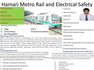
- 2. Metro Rail Project Presentation
- 3. MEP Scope
- 4. Safe Building Electrical Earthing & Lighting
- 6. Follow Electrical Safety(Earthing+Bondng) IEC/IEEE/NFPA Guide Line
- 7. Arc –Spark = Surge in Systems= Result Fires
- 8. India Smart Power Generation & Utilization
- 9. RailwayElectrical and Telecom Guide Line
- 12. Copper Boned Solid Rod as per UL467
- 14. Copper Bonded Rod Life Driven Rod Advanced Driven Rod Grounding Plate Concrete Encased Electrode Building Foundation Water Pipe Electrolytic Electrode Resistance-to- Ground (RTG) Poor Average Poor Average Above Average Poor to Excellent** Excellent Corrosion Resistance Poor Good Poor Good * Good * Varies High Increase in RTG in Cold Weather Highly Affected Slightly Affected Highly Affected Slightly Affected Slightly Affected Minimally Affected Minimally Affected Increase in RTG over Time RTG Worsens RTG typically unaffected RTG Increases RTG typically unaffected RTG typically unaffected RTG typically unaffected RTG Improves Electrode Ampacity Poor Average Average Average * Above Average * Poor to Excellent** Excellent Installation Cost Average Excellent Below Average Below Average Average Average Poor Life Expectancy Poor5–10 years Average15–20 years Poor5-10 years Average *15-20 years Above Average *20-30 years Below Average*10-15 years Excellent30-50 years
- 15. Best Practice
- 16. Driven rods are relatively inexpensive to purchase, however ease of installation is dependent upon the type of soil and terrain where the rod is to be installed. The steel used in the manufacture of a standard driven rod tends to be relatively soft. Mushrooming can occur on both the tip of the rod, as it encounters rocks on its way down, and the end where force is being applied to drive the rod through the earth. Driving these rods can be extremely labor-intensive when rocky terrain creates problems as the tips of the rods continue to mushroom. Often, these rods will hit a rock and actually turn back around on themselves and pop back up a few feet away from the installation point. Because driven rods range in length from 8 to 10 feet, a ladder is often required to reach the top of the rod, hi h a e o e a safet issue. Ma falls ha e resulted fro perso el tr i g to literall ha k these rods into the earth, while hanging from a ladder, many feet in the air. The National Electric Code (NEC) requires that driven rods be a minimum of 8 feet in length and that 8 feet of length must be in direct contact with the soil. Typically, a shovel is used to dig down into the ground 18 inches before a driven rod is installed. The most common rods used by commercial and industrial contractors are 10 ft in length. Many industrial specifications require this length as a minimum. A common misconception is that the copper coating on a standard driven rod has been applied for electrical reasons. While copper is certainly a conductive material, its real purpose on the rod is to provide corrosion protection for the steel underneath. Many corrosion problems can occur because copper is not always the best choice in corrosion protection. It should be noted that galvanized driven rods have been developed to address the corrosion concerns that copper presents, and in many cases are a better choice for prolonging the life of the grounding rod and grounding systems. Generally speaking, galvanized rods are a better choice in all but high salt environments. An additional drawback of the copper-clad driven rod is that copper and steel are two dissimilar metals. When an electrical current is imposed, electrolysis will occur. Additionally, the act of driving the rod into the soil can damage the copper cladding, allowing corrosive elements in the soil to attack the bared steel and further decrease the life expectancy of the rod. Environment, aging, temperature and moisture also easily affect driven rods, giving them a typical life expectancy of five to 15 years in good soil conditions. Driven rods also have a very small surface area, which is not always conducive to good contact with the soil. This is especially true in rocky soils, in which the rod will only make contact on the edges of the
- 17. Corrosion
- 21. Copper Clad Steel Conductor
- 24. GI Rod and Flat Strip Size
- 25. Lightning Strikes Lost of Lives and Assests we have to protect Advance Lightning Protection (ESE Type) NC17-102 A strike can average 100 million volts of electricity Current of up to 100,000 amperes Can generate 54,000 oF Lightning strikes somewhere on the Earth every second Kills Many Lives
- 26. Surge Protection Is A Must
- 27. Early Streamer Lightning Protection(1) Advance Systems for ProtectionNFC 17-102
- 28. Early Streamer Lightning Protection(2) Advance Systems for ProtectionNFC 17-102
- 30. IEC Declaration by CENELEC for NFC17-102
- 31. BT has confirmed that ESE National Standards would remain valid and thus BT recognized there ould e o e ide e of o fli t et ee NF C ‐ a d IEC EN ‐ sta dards a d consequently there is no reason, technical or otherwise, for the withdrawal of the respective national standard.BT has requested that this standard be modified in order to cancel all refere e to the IEC EN ‐ series, allowing the NF C ‐ sta dard to e ist, ith the proposal of possible future migration to international level (lEC). Accordingly, it was established that European ESE standards (France, Spain, Portugal, Slovaquia, etc.) will not conflict with other European standards and will remain valid. • GIMELEC would draw your attention to the fact that the ter s of refere e of NF C ‐ a d • other standards, addressing alternative terminals (NF C ‐ , PR EN ‐ ‐ ) ere fro the • outset, er differe t. It is a fa t that NF C ‐ , whilst referring to ESE Technology also • comments on other standards for lightning protection systems, particularly incorporating • faraday cage, franklin rod and catenary wire systems. the 'camouflaging' of NF C ‐102 by IEC EN • ‐ and its proponents, that FRENCH STANDARD NF C ‐ is still in full force.
- 32. National Building Code 2017 in USA
- 33. National Building Code 2017 in USA
- 34. Latest Solar Project ESE Type LA Documents
- 35. IEC 62305 and NFC17-102
- 36. JMV Earthing Surge Protection
- 37. Contact Professionals for Advise
- 38. We Protect You Use Electrical Safety Earthing & Protection
- 39. Contact our Team JMV INDIA Leader and Insperation behind Mr.Neeraj Saini neeraj@jmv.co.in Mr.Mahesh Chandra Manav Brand JMV HOD manav@jmv.co.in www.jmv.co.in Moblie -919910398999 Telecom -9191204590000