
Recommended
Recommended
More Related Content
What's hot
What's hot (20)
Similar to High Performance Thin Layer Chromatography (HPTLC) instrumentation
Similar to High Performance Thin Layer Chromatography (HPTLC) instrumentation (20)
More from MadhuraNewrekar
Recently uploaded
Recently uploaded (20)
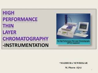
High Performance Thin Layer Chromatography (HPTLC) instrumentation
- 1. -MADHURA NEWREKAR M. Pharm (QA) -INSTRUMENTATION 1
- 2. INTRODUCTION • It is the major advancement of TLC principle. • The technique is more modernized. • Advantages over TLC. • Short time duration. • Better resolution. • More sensitivity. • Ease of quantification. 2
- 3. INSTRUMENTATION • Stepwise procedure include: 1.Preparation of plates 2.Sample application 3.Chromatogram development 4.Derivatization 5.Chromatogram evaluation 6.Scanning and documentation 3
- 4. PLATES • Pre-coated plates: • Wider choice for stationary phase.eg : Silica , alumina , cellulose , C18 , C8. • Particle size is 2-7 μm. • Pore size is smaller and more uniform. • Thickness is 0.2 mm. • If the plates are stored for longer duration of time, they need to be activated before use. 4
- 5. MARKETED EXAMPLES OF PRECOATED PLATES 5
- 6. SAMPLE APPLICATION • Samples are carefully taken with special syringe (Hamilton syringe). • The volume ranges available are 0.5μl ,1μl , 2μl , 5μl. • The syringe is filled carefully to avoid the presence of air bubbles as it will affect the volume of sample. 6
- 7. • It is connected to a nitrogen gas chamber . • The pressure to be used is 60-90 psi (4-6 bar). 7
- 8. • Plate size will vary according to sample number. • Samples are dried in the dessicator. 8
- 9. CHROMATOGRAM DEVELOPMENT • Chamber saturation is required for effective separation. • Before the development of chromatogram the chamber is saturated with vapors of mobile phase. • If the chamber saturation is not done the mobile phase rising through plate will get evaporated and the separation will not be effective. 9
- 10. • Flat bottom chamber: • Twin trough chamber: 1.Low solvent consumption 2.Reproducible preconditioning of the layer 10
- 11. • Horizontal developing chamber: • The HPTLC plate is developed from both opposing sides towards the middle, provided the separation distance of 45 mm. 11
- 12. DERIVATIZATION AND CHROMATOGRAM EVALUATION • The developed plates are observed in the UV cabinet using the wavelengths 254 nm or 366 nm ,for identifying the compounds. 12
- 13. • If the separated compounds are fluorescent in nature , they can be detected using UV cabinet, If the separated compound are not fluorescent , then the fluorescent material is incorporated into stationary phase. • Post chromatogram derivatization e.g. concentrated sulfuric acid. Many organic compound get charred due to sulfuric acid and produce black or brown spots. • Other reagents used : Iodine,Ninhydrin reagent. 13
- 14. DOCUMENTATION SYSTEM • Digistore 2 ( CAMAG ): • It has a digital camera with high resolution which is connected to winCATS software. • It has an illumination unit (Reprostar 3) which will provide the short , long wavelengths and white light. 14
- 15. SCANNER • For quantitative estimation of different compounds at their λmax can be carried out ,since the scanner provides the measurement at wavelengths in the range of 200-400nm. 15
- 16. • In the scanner , each sample band is brought in the path of a required wavelength. • The peaks are recorded and compared with standard. • Thus scanner makes in situ and accurate quantification by HPTLC. • Advantage : There is no need of removal of the separated components unlike TLC which pose the chances for errors. 16
- 17. • A scanning densitometer has the following components: • Light source: hydrogen lamp ,mercury vapor lamp , xenon lamp . • Collimating lens: It makes the beam parallel before entering it into monochromator. • Monochromator: Either a single or double monochromators are used according to the type of scanning densitometer. 17
- 18. • A converging lens: A beam is converged to focus on the separated compounds, When it gets reflected back it falls on the detector. • Detector : An effective detector such as photomultiplier tube is employed for measurement of reflected beam. A signal produced by the detector indicates the concentration of compound present in that band. 18
- 19. • A stepping motor: In order to bring each spot in the focus of a converged beam of radiation it is used in densitometers. It moves a plate under the scanned light beam in order to scan the plate. 19
- 20. CONCLUSION • The automation at different steps provide more accuracy , better resolution . Lower limit of detection in HPTLC. • One recent approach to automation has been the use of piezoelectric devices and inkjet printers for applying sample. • Being more advanced , the usage of HPTLC is well appreciated and accepted all over the world. 20
- 21. REFERENCES • Dr Supriya S Mahajan;Instrumental methods of analysis;2010;Page no: 270-274. • CAMAG; Basic tools for thin layer chromatography ;Edition 2017;Page no:10-17. • Skoog , Holller , Nieman; Instrumental Analysis; 7th edition ;2009;Page no:217-225. • Dr P D Sethi; HPTLC;1st edition ;1996,Page no:25,30-48. 21
- 22. THANK YOU 22
Editor's Notes
- In case a longer separationDistance is desired, the Horizontal Developing Chamber can be used For development from one side. In the Horizontal Developing Chamber, a plate can be developed in the sandwich configuration as well as in the tank configuration. This permits the number of samples to be doubled as compared with development in A tank,