VICTOR MAESTRE RAMIREZ - Planetary Defender on NASA's Double Asteroid Redirec...
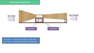
Measure Lift and Drag Forces Using Load Cells
1. Load Cell 1
Working of Load Cells
Air Inlet Air Outlet
Load Cell 2
Load Cell 1 is used for calculation of Lift force.
Load Cell 2 is used for calculation of Drag force
2. Gadgets used:
1. Anemometer : Device used for measuring wind speed
2. Fog machine
Use: To observe the air flow patterns around object
Note: You can make DIY fog
machine.
Using : Dryer, cotton, glycerol
3. 3. Fan with a controller
4. 3D Printed objects
Use: To change the speed of the wind
For example: Car, Aeroplane, Airfoil
4. Formula: CL = FL
½ * ρ * V2 * A
Where FL = Lift force shown by load cell 1
ρ = Density of the fluid in which object is placed
V = Velocity of the fluid
A = Projected area of object taken from top
Calculations of Lift coefficient
5. Formula: CD = FD
½ * ρ * V2 * A
Where FD = Drag force shown by load cell 2
ρ = Density of the fluid in which object is placed
V = Velocity of the fluid
A = Projected area of object taken from front side.
Calculations of Drag coefficient
6. Important points:
1. The size of the object placed inside the test section should be such
that it does not disturb the flow over surrounding walls of the test
section.
2. The clamps should be rigidly fixed so that deflection occurs in the
load cell only.
7. Comparison of Experimental values with Standard values
To confirm the experimental result with the standard one.
Step1- Use airfoil as an object. For e.g. NACA0012
Step4- Go to website http://www.airfoiltools.com/ and find the standard graphs.
Step2- Calculated Cd and CL for it at different angle of attacks (AOA).
Step3- Plot the graph between-
Cd vs α (AOA) and CL vs α (AOA)
Step5- Compare both experimental and standard values
8.
9. Note: If experimental plot
matches with these plots
then it means readings are
correct.
Velocity of air = 10m/s
Chord length = 4in or 0.1016m
Range for Re = 50,000 –1,00,000