
Recommended
More Related Content
Similar to reusablelaunchvehicle-180316021818.pptx
Similar to reusablelaunchvehicle-180316021818.pptx (20)
More from rajmohonsarkar
Recently uploaded
Recently uploaded (20)
reusablelaunchvehicle-180316021818.pptx
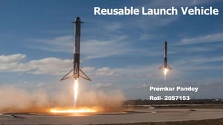
- 1. Reusable Launch Vehicle Premkar Pandey Roll- 2057153
- 2. Content • Introduction • History • Present • Working Of RLV • Design Of RLV Body • Blue Print Of Falcon 9 • Stage Of Orbit • Vertical Landing • Backward Propulsion • Mid Air Recovery • Preparing For Reuse • Calculation • Advantages & Disadvantaged • Conclusion
- 3. INTRODUCTION A Reusable launch vehicle (RLV) refers to a vehicle which can be used for several missions. A Reusable Launch Vehicle is the space analog of an aircraft. Ideally it takes off vertically on the back of an expendable rocket and then glides back down like an aircraft. During landing phase, an RLV can either land on a runway or perform a splashdown. The m ain advantage of an RLV is it can be used multiple times, hopefully with low servicing costs. The expendable rocket that is used for launching the RLV can also be designed to be used multiple times.
- 4. H!STORY The thought of Reusable launch vehicles started in 1950’s, But serious attempts at completely reusable launch vehicles started in the 1990s. The most prominent were McDonnell-Douglas DC-X Lockheed Martin X-33 VentureStar. DC-X X-33 VentureStar
- 5. PRESENT 🞅SpaceX is a recent player in the private launch market 🞅 succeeding in converting its Falcon 9 expandable launch vehicle into a partially reusable vehicle 🞅by returning the first stage for reuse.
- 6. On 23 November 2015, Blue Origin New Shepard rocket became the first proven Vertical Take-off Vertical Landing (VTVL) rocket which can reach space 100.5 kilometers
- 7. WORKING OF AN RLV 🞅Subsonic and supersonic sta g e Upto about 100,000 feet or 30 km. Use a combination of conventional jet-engine and ramjet engine. Plane is accelerated to a speed of mach 4 or mach 5 🞅 Hypersonic stage At an altitude of about 100,000 feet and at a velocity of about mach 4. Combustion and ignition takes place in milliseconds. Scramjet engines takes RLV to mach 15.
- 8. 🞅S p a c e stag e Rocket engines are fired as there isn’t enough oxygen for scramjet engines. RLV is a c c elerated to m a c h 25. Rocket engine takes RLV to payload release site a n d required operations are performed 🞅🞅Re Entry Stage RLV performs de-orbit operations to slow itself down. It drops to lower orbit and enters upper atmospheric layers. RLV uses its aerodynamics to glide down once it reaches dense air
- 9. DESIGN OF AN RLV BODY: 🞅 The body: has to withstand very high stresses. It has to cope with the rapid change in temperatures which changes from -250°C in shade to 250°C in direct sunlight. 🞅 Wings: Delta wings provides enough lift to fly to space and also reduce the friction during re-entry. 🞅 Cockpit: Cockpit has double-paned glass windows which can withstand the force of flight, pressure and vacuum. 🞅 Oxygen bottles are used to add breathable air. An absorber system removes the exhaled carbon dioxide. 🞅 Electrical Power: The power required is taken from lithium batteries which could be charged, if needed by using solar energy.
- 11. STAGES TO ORBIT Single-stage-to-orbit (SSTO) reaches the space orbit carrying small payloads of 9,000 to 20,000kg without losing any hardware to LEO. Two-stage-to-orbit (TSTO or DSTO) are two independent vehicles which interactions while launching. Cross Feed has two or three similar stages are stacked side by side, and burn in parallel. They carry heavy payloads to outer space.
- 12. VERTICAL LANDING 🞅 Parachutes could b e used to land vertically, either at sea, or with the use of small landing rockets, on land 🞅 Rockets could b e used to softland the vehicle on the ground from the subsonic speeds reached at low altitude. 🞅 This typically requires about 10% of the landing weight of the vehicle to b e propellant. 🞅 Alternately, autogyro or helicopter rotor. This requires perhaps 2-3% of the landing weight for the rotor
- 13. RETRO-PROPULSION/ BACKWARD PROPULSION 🞅Retro-propulsion means firing your rocket engines against your velocity vector in order to decelerate. 🞅 The vehicle fires its rockets towards the surface to slow the craft’s descent, after parachutes had already brought it below the speed of sound. 🞅It is very expensive in the sense that the fuel required for landing must be carried to space, which erodes the useable payload capacity of the launch system.
- 14. Mid-Air Recovery (MAR) The reentering vehicle is slowed by means of parachutes, and then a specially equipped aircraft matches the vehicle's trajectory and catches it in mid-air . This approach a voids high impact accelerations and/or emersion in salt water. MAR can be up to (and beyond) a 10 ton payload. It has been successfully demonstrated for 1000 lbs class objects
- 16. PREPARING FOR REUSE 🞅 The vehicle requires extensive inspection a n d refurbishment. 🞅 Each a n d every part of the launch vehicle n e e d e d to b e individually inspected. For example the orbiter’s thermal protection tiles n e e d e d to b e individually inspected (and potentially replaced). 🞅 Main engines n e e d e d to b e removed to undergo extensive inspection a n d overhaul. 🞅 Parts contaminated with o c e a n salt water a n d h a d to b e cleaned, disassembled, a n d refurbished before reuse.
- 17. Calculations related to reusable launch vehicles (RLVs) can vary depending on the specific design and mission parameters of the vehicle, but here are some common calculations Delta-V: The delta-v (change in velocity) required for an RLV to reach a desired orbit or destination is an important calculation. This can be determined using the rocket equation, which takes into account the mass of the vehicle, the mass of the propellant, and the specific impulse of the engines. The delta-v required will depend on factors such as the altitude and inclination of the target orbit or destination. Calculations delta-V = ln (m0/m1) x Isp x g0 Where: •delta-V is the change in velocity required for the RLV to reach its destination. •ln is the natural logarithm function. •m0 is the initial mass of the vehicle, including the propellant and payload. •m1 is the final mass of the vehicle, which is the mass of the vehicle without the propellant. •Isp is the specific impulse of the RLV's engines, which measures the efficiency of the engine in converting propellant into thrust. •g0 is the standard gravitational acceleration at sea level (9.81 m/s^2). The equation states that the delta-V required is proportional to the natural logarithm of the initial to final mass ratio, the specific impulse of the engines, and the standard gravitational acceleration.
- 18. The payload capacity of an RLV is another important calculation. This is the maximum weight of cargo, equipment, or passengers that the vehicle can carry to orbit or to another destination. The payload capacity will depend on the size and mass of the vehicle, the amount of fuel required, and the desired orbit or destination. Payload capacity = (m0 - m1) x (1 - e) Where: Payload capacity is the maximum weight of cargo, equipment, or passengers that the RLV can carry. m0 is the initial mass of the vehicle, including the propellant and payload. m1 is the final mass of the vehicle, which is the mass of the vehicle without the propellant. e is the fraction of the initial mass that is used as propellant, also known as the mass fraction. Payload Capacity
- 19. RLVs experience extreme temperatures during launch and re-entry, which can cause damage to the vehicle and its payload. Calculating the required thickness and composition of the thermal protection system (TPS) is important to ensure the vehicle and its payload are protected. This calculation will depend on factors such as the temperature and pressure of the vehicle's outer surface, the speed of the vehicle during re-entry, and the materials used in the TPS. To perform thermal protection calculations, the following steps can be taken: Determine the required temperature: The first step is to determine the desired temperature that needs to be maintained within the system or structure. This will typically be based on the intended use of the system or structure. Calculate the heat transfer rate: The next step is to calculate the heat transfer rate between the system or structure and the environment. This can be done using the following formula: Q = U * A * (Tin - Tout) Where Q is the heat transfer rate, U is the overall heat transfer coefficient, A is the surface area of the system or structure, Tin is the temperature inside the system or structure, and Tout is the ambient temperature outside the system or structure. Thermal Protection
- 20. 3.Determine the required insulation thickness: Once the heat transfer rate has been calculated, the required insulation thickness can be determined using the following formula: t = (Q * d) / (k * (Tin - Tout)) Where t is the required insulation thickness, Q is the heat transfer rate, d is the distance between the inner and outer surfaces of the system or structure, k is the thermal conductivity of the insulation material, Tin is the temperature inside the system or structure, and Tout is the ambient temperature outside the system or structure. 4.Select an appropriate insulation material: Based on the required insulation thickness, an appropriate insulation material can be selected that has the required thermal conductivity and other properties. 5.Verify the insulation: Once the insulation has been installed, it is important to verify that it is providing the required thermal protection. This can be done using various testing methods, such as infrared imaging or thermocouple measurements.
- 21. RLVs must be aerodynamically stable during all phases of flight, from launch to landing. Calculating the required size and shape of the vehicle's fins, wings, or other aerodynamic features is important to ensure stable flight. This calculation will depend on factors such as the speed and altitude of the vehicle, the weight and distribution of the payload, and the desired maneuverability of the vehicle. One common formula used to calculate the aerodynamic stability derivatives for an aircraft is the linearized equations of motion. These equations relate the aircraft's motion to the various external forces acting upon it, including the aerodynamic forces and moments, the gravitational forces, and any other external forces such as engine thrust or control surface deflections. The linearized equations of motion can be written as follows: [d/dt] [u v w p q r]^T = [Fg + Fa + Fp + Fc]^T / m [d/dt] [phi theta psi]^T = [p cos(theta) - q sin(theta)] / cos(phi), [q cos(phi) sin(theta) + r sin(phi)],[q sin(phi) sin(theta) - r cos(phi)]^T Where: •u, v, and w are the velocity components in the x, y, and z directions, respectively •p, q, and r are the angular velocity components about the x, y, and z axes, respectively •Fg is the gravitational force •Fa is the aerodynamic force •Fp is the propulsion force •Fc is the control force •m is the mass of the aircraft •phi, theta, and psi are the roll, pitch, and yaw angles, respectively. Aerodynamic Stability
- 22. Economy of reuse 🞅The general cost estimation for an expendable launch vehicle varies from Rs 12,30,000 to Rs 16,50,000/KG 🞅 whereas a reusable launch vehicle cost just varies between Rs 16,500 to Rs1,65,000/KG
- 23. Advantages 1. Compared to other launch vehicles the F9R is a reusable launch vehicle. 2. By using F9R the cost is being reduced by 40 percent. 3. Total liftoff mass1400 metric tons (14 Lakh Kilo) by using in a single launch have been planned this year. 4. The stage-1 can be landed any were means in a ship or sea drone which is very efficient. 5. Falcon 9R is a highly reliable launch vehicle. Disadvantages 1. The Falcon 9 experiences major temperature changes during its flights, as well as intense pressures and vibrations from the winds in the atmosphere. 2. Refurbishing a rocket engine is often expensive. And if those repairs take too long, company can’t launch its vehicles as frequently. Refurbishment costs are too expensive. 3. To launch F9R the climate condition should be absolute normal, if anything goes wrong the return stage-1 of falcon 9 will get damaged. 4. The vertical landing of F9R is very complicated.
- 24. conclusion Reusable launch systems have the highest development costs and technical risks RLV reduce cost very much by avoiding repeatedly making of new use and throw launch vehicles technology is within current state of the art. Current efforts to economically recover and reuse launch vehicle elements are more promising than they have ever been. International Space Station needs periodical replenishment and may need other support missions from earth even at short notice. RLVs become very useful in these circumstances
- 25. References Research Papers Bhavana Y, Mani Shankar N and Prarthana BK (2013) “Reusable Launch Vehicle: Evolution Redefined”. J Aeronaut Aerospace Eng: 2-2 Moham ed M. Ragab, F . McNeil Cheatwood, Stephen J. Hughes and Allen Lowry “Launch Vehicle Recovery and Reuse”. Acta Astronautica: 41-11
- 26. Thank you all And its time to clear your doubts