SlideShare a Scribd company logo
1 of 26
Download to read offline
Assembly level Programming using 8085MP
Prof. K. Adisesha 1
Functional Pin Diagram of 8085
8085 Pin Diagram and functional pin diagram of 8085 microprocessor respectively.
The signals of 8085 Pin Diagram can be classified into seven groups according to their functions.
1. Power supply and frequency signals:
➢ Vcc: It requires a single +5 V power supply, Vss : Ground reference.
➢ X1 and X2 : A tuned circuit like LC, RC or crystal is connected at these two. The internal clock
generator divides oscillator frequency by 2, therefore, to operate a system at 3 MHz, the crystal of tuned
circuit must have a frequency of 6 MHz.
➢ CLK OUT : This signal is used as a system clock for other devices. Its frequency is half the oscillator
frequency.
2. Data bus and address bus:
Assembly level Programming using 8085MP
Prof. K. Adisesha 2
➢ AD0 to AD7 : The 8 bit data bus (D0 – D7) is multiplexed with the lower half (A0 – A7) of the 16 bit
address bus, These lines are used as a bi-directional data bus.
➢ A8 to A15 : The upper half of the 16 bit address appears on the address lines A8 to A15. These lines are
exclusively used for the most significant 8 bits of the 16 bit address lines.
3. Control bus
➢ A) ALE (Address Latch Enable): We, know that AD0 to AD7 lines are multiplexed and the lower half
of address (A0 – A7) is available only during T1 of the machine cycle. This lower half of address is also
necessary during T2 and T3 of machine cycle to access specific location in memory or I/O port.
➢ B) RD and WR: These signals are basically used to control the direction of the data flow between
processor and memory or I/O device/port. A low on RD indicates that the data must be read from the
selected memory location or I/O port via data bus. A low on WR indicates that the data must be written
into the selected memory location or I/O port via data bus.
➢ C) IO/M, S0 and S1: IO/M indicates whether I/O operation or memory operation is being carried out.
S1 and S0 indicate the type of machine cycle in progress.
➢ D) READY: It is used by the microprocessor to sense whether a peripheral is ready or not for data
transfer. If not, the processor waits. It is thus used to synchronize slower peripherals to the
microprocessor.
4. Interrupt signals
➢ The 8085 Pin Diagram has five hardware interrupt signals: RST 5.5, RST 6.5, RST 7.5, TRAP and
INTR. The microprocessor recognises interrupt requests on these lines at the end of the current
instruction execution.
➢ The INTA (Interrupt Acknowledge) signal is used to indicate that the processor has acknowledged an
INTR interrupt. 5. Serial I/O signals
➢ SID (Serial I/P Data): This input signal is used to accept serial data bit by bit from the external device.
➢ SOD (Serial O/P Data) : This is an output signal which enables the transmission of serial data bit by bit
to the external device.
6. DMA signals
➢ A) HOLD: This signal indicates that another master is requesting for the use of address bus, data bus
and control bus.
➢ B) HLDA: This active high signal is used to acknowledge HOLD request.
7. Reset signals: A low on this pin
➢ Sets the program counter to zero (0000H).
➢ Tri-states the data bus, address bus and control bus.
On reset, the PC sets to 0000H which causes the 8085 Pin Diagram to execute the first instruction from
address 0000H. The power-on reset circuit can be used to ensure execution of first instruction from address
0000H.
RESET OUT: This active high signal indicates that processor is being reset. This signal is synchronized to the
processor clock and it can be used to reset other devices connected in the system
Assembly level Programming using 8085MP
Prof. K. Adisesha 3
8085 Architecture
8085 is an 8-bit microprocessor designed by Intel in 1977 using NMOS technology.
It has the following configuration –
➢ 8-bit data bus
➢ 16-bit address bus, which can address upto 64KB
➢ A 16-bit program counter
➢ A 16-bit stack pointer
➢ Six 8-bit registers arranged in pairs: BC, DE, HL
➢ Requires +5V supply to operate at 3.2 MHZ single phase clock
Assembly level Programming using 8085MP
Prof. K. Adisesha 4
8085 Microprocessor – Functional Units
8085 consists of the following functional units –
Accumulator
It is an 8-bit register used to perform arithmetic, logical, I/O & LOAD/STORE operations. It is connected to
internal data bus & ALU.
Arithmetic and logic unit
As the name suggests, it performs arithmetic and logical operations like Addition, Subtraction, AND, OR, etc.
on 8-bit data.
General purpose register
There are 6 general purpose registers in 8085 processor, i.e. B, C, D, E, H & L. Each register can hold 8-bit
data.
These registers can work in pair to hold 16-bit data and their pairing combination is like B-C, D-E & H-L.
Program counter It is a 16-bit register used to store the memory address location of the next instruction to be
executed.
Microprocessor increments the program whenever an instruction is being executed, so that the program counter
points to the memory address of the next instruction that is going to be executed.
Stack pointer It is also a 16-bit register works like stack, which is always incremented/decremented by 2 during
push & pop operations.
Temporary register It is an 8-bit register, which holds the temporary data of arithmetic and logical operations
Flag register
It is an 8-bit register having five 1-bit flip-flops, which holds either 0 or 1 depending upon the result stored in
the accumulator.
These are the set of 5 flip-flops –
➢ Sign (S)
➢ Zero (Z)
➢ Auxiliary Carry (AC)
➢ Parity (P)
➢ Carry (C)
Its bit position is shown in the following table –
Assembly level Programming using 8085MP
Prof. K. Adisesha 5
Instruction register and decoder
It is an 8-bit register. When an instruction is fetched from memory then it is stored in the Instruction register.
Instruction decoder decodes the information present in the Instruction register.
Timing and control unit
It provides timing and control signal to the microprocessor to perform operations. Following are the timing and
control signals, which control external and internal circuits –
➢ Control Signals: READY, RD’, WR’, ALE
➢ Status Signals: S0, S1, IO/M’
➢ DMA Signals: HOLD, HLDA
➢ RESET Signals: RESET IN, RESET OUT
Interrupt control
As the name suggests it controls the interrupts during a process. When a microprocessor is executing a main
program and whenever an interrupt occurs, the microprocessor shifts the control from the main program to
process the incoming request. After the request is completed, the control goes back to the main program.
There are 5 interrupt signals in 8085 microprocessors: INTR, RST 7.5, RST 6.5, RST 5.5, TRAP.
Serial Input/output control
It controls the serial data communication by using these two instructions: SID (Serial input data) and SOD
(Serial output data).
Address buffer and address-data buffer
The content stored in the stack pointer and program counter is loaded into the address buffer and address-data
buffer to communicate with the CPU. The memory and I/O chips are connected to these buses; the CPU can
exchange the desired data with the memory and I/O chips.
Address bus and data bus
Data bus carries the data to be stored. It is bidirectional, whereas address bus carries the location to where it
should be stored and it is unidirectional. It is used to transfer the data & Address I/O devices.
Assembly level Programming using 8085MP
Prof. K. Adisesha 6
Program List
1. Assembly level program to exchange two 16-bit numbers
2. Assembly level program to addition two 8-bit numbers
3. Assembly level program to subtract two 8-bit numbers
4. Assembly level program to addition two 16-bit numbers
5. Assembly level program to subtract two 16-bit numbers (x>y)
6. Assembly level program to convert hexadecimal to BCD
7. Assembly level program to find 1’s compliment 16-bit number
8. Assembly level program to find whether the given number is positive negative or zero
9. Assembly level program to generate Fibonacci series
10.Assembly level program to square of hexadecimal number
11.Assembly level program to addition of n-byte numbers
12.Assembly level program to addition of two n-byte numbers
13.Assembly level program to implement block transfer
14.Assembly level program to implement block exchange
15.Assembly level program to find largest of two numbers
16.Assembly level program to find the largest of n-numbers
17.Assembly level program to find the smallest of 2-numbers
18.Assembly level program to find the smallest of n-numbers
19.Assembly level program to sort the array of numbers in ascending order
20.Assembly level program to multiplication of two decimal numbers
Assembly level Programming using 8085MP
Prof. K. Adisesha 7
1) PROGRAM TO EXCHANGE TWO 16 BIT NUMBERS
Address Hex-code Label Opcode Operand Comments
8000 2A,00, F0 LHLD F000 H
Load memory from
specified locations.
8003 EB XCHG
Exchange contents of HL
& DE pairs.
8004 2A,00, F1 LHLD F100 H
Load memory from
specified locations.
8007 22,00, F0 SHLD F000 H
Store memory to specified
locations.
800A EB XCHG
Exchange contents of HL
& DE pairs.
800B 22,00, F1 SHLD F100H
Store memory to specified
locations.
800E 76 HLT Halt
INPUT (Before
execution)
F001 ; F000
12 ; AB
F101 ; F100
3C ; DE
OUTPUT (After
execution)
F001; F000
3C ; DE
F101 ; F100
12 ; AB
Assembly level Programming using 8085MP
Prof. K. Adisesha 8
2) PROGRAM TO ADDITION TWO 8 BIT NUMBERS
Address Hex-code Label Opcode Operand Comments
8000 3E, XX MVI A, XX Move immediately to A, XX
8002 06, YY MVI B, YY Move immediately to B, YY
8004 80 ADD B Add A=A+B
8005 32, 00, F0 STA F000 H
Store contents of A in
specified location
8008 D2, 10, 80 JNC AHEAD1 Jump on no carry to Ahead1
800B 3E, 01 MVI A,01 H Move immediately to A, 01h
800D C3, 12, 80 JMP AHEAD2
Unconditional Jump to
Ahead2
8010 3E, 00 AHEAD1 MVI A, 00 H Move immediately to A, 00h
8012 32, 01, F0 AHEAD2 STA F001
Store contents of A in
specified location
8015 76 HLT Halt
INPUT (Before
execution)
XX ; YY
20 ; 10
XX ; YY
2B : FA
OUTPUT (After
execution)
F001 ; F000
00 30
F001 ; F000
01 : 25
Assembly level Programming using 8085MP
Prof. K. Adisesha 9
3) PROGRAM TO SUBTRACT TWO 8 BIT NUMBERS
Address Hex-code Label Opcode Operand Comments
8000 3E,XX MVI A, XX Move immediately to A, XX
8002 06, YY MVI B, YY Move immediately to B, YY
8004 80 SUB B Subtract A=A-B
8005 32, 00, F0 STA F000 H
Store contents of A in specified
location
8008 D2, 10, 80 JNC AHEAD1 Jump on no carry to Ahead1
800B 3E, 01 MVI A,01 H Move immediately to A, 01h
800D C3, 12, 80 JMP AHEAD2 Unconditional Jump to Ahead2
8010 3E, 00 AHEAD1 MVI A, 00 H Move immediately to A, 00h
8012 32, 01, F0 AHEAD2 STA F001
Store contents of A in specified
location
8015 76 HLT Halt
INPUT (Before
execution)
XX; YY
20 ; 10
XX; YY
2B : FA
OUTPUT (After
execution)
F001; F000
00 10
F001 ; F000
01 : 31
Assembly level Programming using 8085MP
Prof. K. Adisesha 10
4) PROGRAM TO ADDITION TWO 16 BIT NUMBERS
Address Hex-code Label Opcode Operand Comments
8000 AF XRA A Clear accumulator & Flags
8001 2A, 00, F0 LHLD F000
Load memory from specified
locations.
8004 EB XCHG
Exchange contents of HL &
DE pairs.
8005 2A, 00, F1 LHLD F100
Load memory from specified
locations.
8008 19 DAD D Add the contents of HL & DE
8009 22, 00, F2 SHLD F200
Store memory to specified
locations.
800C D2, 10, 80 JNC AHEAD Jump on no carry to AHEAD
800F 3C INR A
Increment contents of
Accumulator by 1
8010 32, 02, F2 AHEAD STA F202
Store memory to specified
locations.
8013 76 HLT Halt
INPUT (Before
execution)
F001: F000
(X)
10 : 20
F101: F100
(Y)
30 : 40
F001: F000
(X)
4A : 2C
F101: F100
(Y)
ED : 5B
OUTPUT (After
execution)
F202:F201:
F200 (X+Y)
01 : 40 : 60
F202:F201:
F200 (X+Y)
01 : 37 : 87
Assembly level Programming using 8085MP
Prof. K. Adisesha 11
5) PROGRAM TO SUBTRACT TWO 16 BIT NUMBERS (X>Y)
Address Hex-code Label Opcode Operand Comments
8000 2A, 00, F0 LHLD F000
Load memory from specified
locations.
8003 EB XCHG
Exchange contents of HL &
DE pairs.
8004 2A, 00, F1 LHLD F100
Load memory from specified
locations.
8007 7D MOV A, L Move content of [L] to [A]
8008 93 SUB E Subtract [E] from [A]
8009 32, 00, F2 STA F200
Store memory to specified
locations.
800C 7C MOV A, H Move content of [H] to [A]
800D 9A SBB D
Subtract with borrow [D] from
[A]
800E 32,01, F2 STA F201
Store memory to specified
locations.
8011 76 HLT Halt
INPUT (Before
execution)
F001: F000 (X)
FA : 2C
F101: F100
(Y)
BD : 5B
OUTPUT (After
execution)
F201: F200 (X-Y) 3C : D1
Assembly level Programming using 8085MP
Prof. K. Adisesha 12
6) Assembly level Program to convert Hexadecimal to BCD
Address Hex Code Label Opcode Operand Comments
9000 21,00,80 LXI H,8000H
Initialise HL register pair as memory
point to load data byte
9003 0E,00 MVI C,00H Clear C to register to store carry
9005 46 MOV B, M Move the hex data to B register
9006 AF XRA A Clear accumulator
9007 C6,01 UP ADI 01 H Add 1 to accumulator
9009 27 DAA
Decimal Adjust Accumulator covert
hexadecimal to BCD
900A D2,0E,90 JNC LOOP
If no carry, jump to the specified
memory location
900D 0C INR C
If there is a carry, increment C
register by 1
900E 05 LOOP DCR B Decrement B by 1
900F C2,07,90 JNZ UP
If counter is not zero, go to the
specified lable UP
9012 32,01,80 STA 8001H
Store the BCD number in memory
location 8001H
9015 79 MOV A, C Move the carry to the accumulator
9016 32,02,80 STA 8002H
Store the carry in the memory
location 8002H
9019 76 HLT Terminate program execution
INPUT (Before execution) 8000 (X) : 2F H 8000 (Y) : 20 H
OUTPUT (After execution) 8001: 47 D, 8002: 00 D 8001: 20 D, 8002: 00 D
Assembly level Programming using 8085MP
Prof. K. Adisesha 13
7) Assembly level Program to find 1’s compliment 16-Bit number
Address Hex-Code Label Opcode Operand Comments
9000 21,00,85 LXI H,8500H
Initialise HL register pair as
memory point to load data byte
9003 7E MOV A, M
Move the lower data byte to
accumulator
9004 2F CMA
Complement the lower data
byte
9005 32,02,80 STA 8502 H
Store the result in memory
location 8502 H
9008 23 INX H
Increment the pointer to get the
higher data byte
9009 7E MOV A, M
Move the higher data byte to
the accumulator
900A 2F CMA
Complement the higher data
byte
900E 32,03,85 STA 8503 H
Store the result in memory
location 8503 H
900E 76 HLT Terminate program execution
INPUT (Before execution)
8501: 8500
8B H : 36 H
8501: 8500
28 H : AB H
OUTPUT (After execution)
8502: 8503
C9 H : 74 H
8502: 8503
54 H : E7 H
Assembly level Programming using 8085MP
Prof. K. Adisesha 14
8) Assembly level Program to find whether the given number is positive negative or zero
Address
Hex-
Code
Label Opcode Operand Comments
8500 21,00,82 LXI H,8100H
Setup HL as memory pointer
with memory address 8200H
8503 7E MOV A, M
Get the data byte as
accumulate
8504 E6, FF ANI FFH
AND accumulator context
with FFH
8506 CA, 0F,85 JZ ZERO
Jump on zero, if the result is
zero jump to specific loop
8509 FA,14,85 JM NEGATIVE
Jump on minus, if D, byte is
1, jump to specified loop
850C F2,19,85 JP POSITIVE If result is zero,
850F 3E,00 ZERO MVI A,00H Move 00H to accumulator
8511 C3,1B,85 JMP LOOP Jump to loop
8514 3E, FF NEGATIVE MVI A, FFH Move FF to accumulator
8516 C3,1B,85 JMP LOOP Jump to loop
8519 3E,01 POSITIVE MVI A,01H Move 01 to accumulator
851B 32,01,82 LOOP STA 8101H
Store the contents of
accumulator to specified
address
851E 76 HLT
Terminate program
execution
INPUT (Before execution) 8100: 74 H 8100: 94 H
OUTPUT (After execution) 8101: 01 H 8101: FF H
Assembly level Programming using 8085MP
Prof. K. Adisesha 15
9) Assembly level Program to generate Fibonacci series
Address Hex-Code Label Opcode Operand Comments
8500 0E,0A MVI C,0AH
Setup a counter by loading count
0AH to C register
8502 21,00,81 LXI H,8100H
Setup HL as memory pointer
with memory address 8100H
8505 7E MOV A, M Get 00H to accumulator
8506 23 INX H
Increment the pointer to get next
data
8507 56 MOV D, M Get 01H to D register
8508 82 LOOP ADD D
Add content of accumulator
with content of D register
8509 27 DAA Decimal adjust accumulator
851A 23 INX H Increment pointer to store sum
851B 77 MOV M, A
Move accumulator content to
next location
851C 7A MOV A, D Move D registers to accumulate
851D 56 MOV D, M
Move content of memory
location to D register
851E 0D DCR C Decrement C to register by 1
850F C2,08,85 JNZ LOOP
If counter value is not zero, go to
the label Loop
8512 76 HLT Terminate program execution
INPUT (Before
execution)
8100: 00 H, 8101: 01 H
OUTPUT (After
execution)
8100 -to - 810A:
00H, 01H, 02H, 03H, 05H, 0DH, 15H, 22H, 37H, 59H
Assembly level Programming using 8085MP
Prof. K. Adisesha 16
10) Assembly level Program to square of Hexadecimal number
Address Hex-Code Label Opcode Operand Comments
8000 21,00,90 LXI H,9000H
Register pair HL is loaded with
memory location 9000H
8003 3E,00 H MVI A,00H
Clear accumulator to avoid addition
of junk values and to store the correct
result
8005 57 MOV D, A Clear register D to save carry
8006 4E MOV C, M
Copy the contents of memory M to
register C and the value in register C
is used as a counter
8007 86 UP ADD M
The contents of M is repeatedly add
with contents of accumulator A until
the counter is 0
8008 D2, 0C, 80 JNC LOOP If no carry jump to label LOOP
800B 14 INR D If carry increment register D by 1
850C 0D LOOP DCR C Decrement the counter(reg C) by 1
800D C2, 07, 80 JNZ UP
If the counter value is not equal to
zero< go back to the label UP
8010 32, 00, 91 STA 9100H
Store the content of the accumulator
(result of square of a number) in
9100H memory location
8013 7A MOV A, D Move the carry to the accumulator
8014 32, 01, 91 STA 9101H
Store the carry in 9101H memory
location
8017 76 HLT Terminate the program execution
INPUT (Before execution) 9000: 02 H 9000: 04 H
OUTPUT (After execution)
9100: 9101
04 H: 00 H
9100: 9101
10 H: 00 H
Assembly level Programming using 8085MP
Prof. K. Adisesha 17
11) Assembly level Program to addition of N-byte numbers
Address Hex-Code Label Opcode Operand Comments
8000 0E, 06H MVI C,06H Set up C reg, counter value 06H bytes.
8002 AF XRA A
Clear accumulator to avoid addition of
junk values and to store the correct
result
8003 47 MOV B, A Clear register B to save carry
8004 21,00,81 LXI H,8100H
Register pair HL is loaded with
memory location 8100H
8007 86 UP ADD M
The contents of memory M is
repeatedly add with the contents of
accumulator A until the counter is 0
8008 D2,0C,80 JNC LOOP If no carry jump to the label LOOP
800B 04 INR B If carry increment register D by 1
800C 23 LOOP INX H
Increment memory pointer to store
next byte to add
800D 0D DCR C Decrement counter (register C) by 1
800E C2,07,80 JNZ UP
If the counter value is not equal to zero,
go back to the label UP
8011 32,00,91 STA 8200H
Store the content of the accumulator
(result of square of a number) in 8200H
memory location
8014 78 MOV A, B Move the carry to the accumulator
8015 32,01,82 STA 8201H
Store the carry in 8201H memory
location
8018 76 HLT Terminate the program execution
INPUT (Before
execution)
8100 -to - 8105:
25H, 31H, 64H, 80H, 15H, 42H
OUTPUT (After
execution)
8200- 91H (Sum), 8201- 01H(Carry)
Assembly level Programming using 8085MP
Prof. K. Adisesha 18
12) Assembly level Program to addition of TWO N-byte numbers
Address Hex-Code Label Opcode Operand Comments
8000 21, 00, 81 LXI H, 8100H
Set up HL as memory pointer source
memory
8003 11, 00, 82 LXI D, 8200 H
Setup DE as a memory pointer for the
destination memory
8006 06, 04H MOV C, 04H
Setup C as a byte counter to transfer data
to new memory location
8008 AF XRA A Clear Accumulator
8009 1A Next LDAX D Get the data byte od 2nd
number to Acc.
800A 8E ADC M Add 1st
and 2nd
number with carry
800B 77 MOV M, A Save the sum in memory pointer by HL
800C 23 INX H
Increment memory pointer HL to store
next byte to add
800D 13 INX D
Increment memory pointer DE to store
next byte to add
800E 0D DCR C Decrement counter (register C) by 1
800F C2,09,08 JNZ Next Go to pointer next if counter is not zero
8012 3E, 00H MVI A,00H Clear accumulator to save carry
8014 17 RAL Move the carry to the accumulator
8015 77 MOV M, A Store the carry in 8201H memory location
8016 76 HLT Terminate the program execution
INPUT (Before execution)
8100 -to - 8103:
35H, 45H, 55H, 65H
8200 -to - 8203:
29H, 14H, 68H, B9H
OUTPUT (After execution)
8100 -to-8103: 5EH, 59H, BDH, 1EH (Sum),
8104- 01H(Carry)
Assembly level Programming using 8085MP
Prof. K. Adisesha 19
13) Assembly level Program to implement block transfer
Address
Machine
code
Label Opcode Operand Comments
9000 21, 00, 80 LXI H, 8000H
Set up HL as memory pointer
source memory
9003 11, 00, 81 LXI D, 8100 H
Setup DE as a memory pointer
for the destination memory
9006 06, 0A MOV B, 0AH
Setup B as a byte counter to
transfer ten bytes of data to new
memory location B is loaded
with 0AH
9008 7E NEXT MOV A, M
Move the data byte of source
memory to accumulator
9009 12 STAX D
Transfer the data byte to the
destination memory
900A 23 INX H
Increment the source memory
pointer to get to the next byte
900B 13 INX D
Increment the memory pointer to
transfer next data byte
900C 05 DCR B
Decrement the counter by 1, if
one data byte is transferred
900D C2, 08, 90 JNZ NEXT
If counter is not zero, go back to
NEXT to transfer next data byte
9010 76 HLT Terminate program execution
INPUT (Before execution)
8000 -to - 8009:
10H, 20H, 30H, 40H, 50H, 60H.70H, 80H, 90H, 0AH
OUTPUT (After execution)
8100 -to - 8109:
10H, 20H, 30H, 40H, 50H, 60H.70H, 80H, 90H, 0AH
Assembly level Programming using 8085MP
Prof. K. Adisesha 20
14) Assembly level Program to implement block exchange
Address Hex-code Label Opcode Operand Comments
9000 06, 05H MVI B,0AH
Setup B as a byte counter to exchange two
16-bit numbers B is loaded with 0AH
9002 21, 50, 80 LXI H, 8000H
Setup HL as a memory pointer for 8000H
memory location
9005 11, 70, 80 LXI D, 8070
Setup DE as a memory pointer for 8100H
memory location
9008 1A loop LDAX D
Move the contents of memory pointer
specified by the DE register pair to
accumulator
9009 4F MOV C, A
Save the contents of accumulator in C
register
900A 7E MOV A, M
Move the data byte of memory pointer
specified by the HL register pair to
accumulator
900B 12 STAX D
Transfer the data byte of HL register pair
memory pointer to DE register pair
memory pointer
900C 71 MOV M, C
Transfer the data byte of DE register pair
memory pointer to the HL register pair
memory pointer
900D 23 INX H
Increment the source memory pointer to
transfer to next data byte
900E 13 INX D
Increment the destination memory pointer
to transfer next data byte
901F 05 DCR B
Decrement counter by 1, if one data byte is
exchanged
9010 C2, 08, 90 JNZ loop
If counter is not zero, go back to repeat to
exchange next data byte
9013 76 HLT Terminate program execution
INPUT (Before
execution)
8000 -to - 8009:
11H, 22H, 33H, 44H, 55H, 66H.77H, 88H, 99H, AAH
8100 -to - 8109:
10H, 20H, 30H, 40H, 50H, 60H.70H, 80H, 90H, 0AH
OUTPUT (After
execution)
8000 -to - 8009:
10H, 20H, 30H, 40H, 50H, 60H.70H, 80H, 90H, 0AH
8100 -to - 8109:
11H, 22H, 33H, 44H, 55H, 66H.77H, 88H, 99H, AAH
Assembly level Programming using 8085MP
Prof. K. Adisesha 21
15) Assembly level Program to find largest of two numbers
Address Hex code Label Opcode Operand Comment
9000 21, 00,85 LXI H, 8000H Setup HL as memory pointer with
memory address 8000H to store 1st
data
byte
9003 7E MOV A, M Moves the data byte stored in 8000H
memory location addressed by H-L
register pair to accumulator
9004 23 INX H Increments the memory pointer by
1(8051) to store the 2nd
data byte
9005 BE CMP M Compares the two numbers
9006 D2,0A,90 JNC NEXT Of no carry larger number is in
accumulator then go NEXT
9009 7E MOV A, M If carry, the larger number in 8051H
memory location then move the larger
number to accumulator
900A 32,03,85 NEXT STA 8102H Stores the larger number in 8502H
memory location.
900D 76 HLT Stop processing
INPUT (Before
execution)
8100 -25H - 8101: 31H
OUTPUT (After
execution)
8102- 31H (Largest number)
Assembly level Programming using 8085MP
Prof. K. Adisesha 22
16) Assembly level Program to find the largest of N-numbers
Address Hex-Code Label Opcode Operand Comment
9000 0E, 0AH MVI C,0AH
Setup C-register with a counter
value 0AH to find the largest of ten
data bytes
9002 21, 00, 85 LXI H, 8500H
Setup HL as memory pointer with
memory address 8500H
9005 7E MOV A, M
Moves the data byte stored in 8500H
memory location to accumulator
9006 0D DCR C
Decrement counter by 1, if the 1st
byte is loaded to accumulator
9007 23 REPEAT INX H
Increments the memory pointer by 1
to store the next data byte
9008 BE CMP M Compares two numbers
9009 D2, 0D,90 JNC NEXT
If no carry larger number is in
accumulator go to NEXT
900C 7E MOV A, M
If carry, the larger number is in
memory pointer then move the
larger number to accumulator
900D 0D NEXT DCR C
Decrement the counter by 1, if one
data byte is checked
900E C2, 07, 90 JNZ REPEAT
If counter is not zero, go to loop
repeat to find the largest of the
remaining data bytes
9011 32, 00, 86 STA 8600H
Store the largest in 8600H memory
location
9014 76 HLT Stop processing
INPUT (Before execution)
8500 -to - 8509:
10H, 20H, 30H, 40H, 50H, 60H.70H, 80H, 90H, A0H
OUTPUT (After execution) 8600- A0H (Largest number)
Assembly level Programming using 8085MP
Prof. K. Adisesha 23
17) Assembly level Program to find the smallest of 2-numbers
Address Hex-code Label Opcode Operand Comment
9000 21, 01,85 LXI H, 8501H
Setup H as memory pointer with
memory address 8051H to store 1st
data byte
9003 7E MOV A, M
Moves the data byte stored in
8051H memory location
addressed by H-L register pair to
accumulator
9004 23 INX H
Increments the memory pointer by
1(8052H) to store the 2nd
data byte
9005 BE CMP M Compares the two numbers
9006 DA,0A,90 JC NEXT
If carry smaller number is in
accumulator, then go to NEXT
9009 7E MOV A, M
If no carry the smaller number in
8052H memory location then
moves the smaller number to
accumulator
900A 32, 00, 86 NEXT STA 8600H
Stores the smaller number in
8503H memory location
900D 76 HLT Stop processing
INPUT (Before
execution)
8100 -25H - 8101: 31H
OUTPUT (After
execution)
8103- 25H (Smallest number)
Assembly level Programming using 8085MP
Prof. K. Adisesha 24
18) Assembly level Program to find the smallest of N-numbers
Address Hex-code Label Opcode Operand Comments
9000 0E, 0AH MVI C,0AH
Setup C-register with a counter
value 0AH to find the largest of
ten data bytes
9002 21, 00, 85 LXI H, 8500H
Setup HL as memory pointer
with memory address 8500H
9005 7E MOV A, M
Moves the data byte stored in
8500H memory location to
accumulator
9006 0D DCR C
Increments the memory pointer
by 1 to store the next data byte
9007 23 REPEAT INX H
Increments the memory pointer
by 1 to store the next data byte
9008 BE CMP M Compares the two numbers
9009 DA,0D, 90 JC NEXT
If carry smaller number is in
accumulator go to NEXT
900C 7E MOV A, M
If no carry, the smaller number
is in memory pointer then move
the smaller number to
accumulator
900D 0D NEXT DCR C
Decrement the counter by 1, if
one data byte is checked
900E C2, 07, 90 JNZ REPEAT
If counter is not zero, go to loop
repeat to find the smallest of the
remaining data bytes
9011 32, 00, 86 STA 8600H
Store the largest in 8600H
memory location
9014 76 HLT Stop processing
INPUT (Before
execution)
8500 -to - 8509:
A0H, 20H, 10H, 40H, 50H, 60H, 90H,
80H, 70H, 30H
OUTPUT (After
execution)
8600- 10H (Smallest number)
Assembly level Programming using 8085MP
Prof. K. Adisesha 25
19) Assembly level Program to sort the array of numbers in ascending order
Address Hex-code Label Opcode Operand Comments
9000 16, 05h MVI D,05H
Setup D-register as counter 1 with
counter value 05H to arrange ten bytes
of numbers in ascending order
9002 21, 00, 85 LOOP3 LXI H, 8500H
Setup HL as memory pointer (M) with
memory address 8500H
9005 0E, 05 MVI C,05H
Setup C-register as counter 2 with a
counter value 05H to arrange ten bytes
of numbers in ascending order
9007 7E LOOP2 MOV A, M
Moves the data byte stored in memory
pointer to accumulator
9008 23 INX H Increment the memory pointer 1
9009 BE CMP M
Compare the contents of memory
pointer with accumulator contents
900A DA,12,90 JC LOOP1
If (A) < (M) jump to Loop1 otherwise
exchange the contents of accumulator
and memory pointer
900D 46 MOV B, M
If (A) < (M) exchange the contents of
memory pointer (M) and (M-1)
900E 77 MOV M, A
Decrement by one if the content of (M-
1) < (m)
900F 2B DCX H
9010 70 MOV M,B
9011 23 INX H
9012 0D LOOP1 DCR C
Decrement by one if the content of (M-
1) < (m)
9013 C2, 07, 90 JNZ LOOP2
If counter is not zero go back to Loop2
to keep smaller number in memory
pointer
9016 15 DCR D Decrement the D-counter by one
9017 C2, 02, 90 JNZ LOOP3
If the counter is not zero go back to
Loop3 to repeat the same operation to
arrange the numbers in ascending order
901A 76 HLT End of program
INPUT (Before execution)
8000 -to - 8009:
30H, 0AH, 10H, 60H, 90H, 40H.70H, 80H, 50H, 02H
OUTPUT (After execution)
8100 -to - 8109:
10H, 20H, 30H, 40H, 50H, 60H.70H, 80H, 90H, 0AH
Assembly level Programming using 8085MP
Prof. K. Adisesha 26
20) Assembly level Program to multiplication of two decimal numbers
Address Hex-code Label Opcode Operand Comments
9000 0E, 08D MVI C, XX D Get multiplied in C register
9002 16, 04D MVI D, YYD Get multiplied in D register
9004 AF XRA A Clear accumulator to save sum
9005 47 MOV B, A
Clear B register to save
generated carry
9006 81 LOOP ADD C
Add multiplicand to
accumulator
9007 27 DAA
Adjust the sum for decimal
value
9008 DA, 0C, 90 JNC LOOP1 If no carry go to Next
900B 04 INR B
If carry B register is
incremented by 1
900C 15 LOOP1 DCR D
Decrement the D register by 1,
if the multiplicand is added to
accumulator once
900D C2, 06, 90 JNZ LOOP
If multiplier is not zero, go to
loop to add multiplicand again
9010 32, 00, 86 STA 8000H
Stores the product in 8600
memory location
9013 78 MOV A, B
Moves the contents of B
register (carry contents) to
accumulator
9014 32, 01,86 STA 8001H
Stores the carry in 8601
memory location
9017 76 HLT Terminate program execution
INPUT (Before execution)
a) XX: YY
08 D: 04 D
b) XX: YY
04 D: 02 D
OUTPUT (After execution)
8001: 8000
00 D: 32 D
8001: 8000
00 D: 08 D

More Related Content

Similar to 8085 ADDITION

Introduction to 8085 Microprocessor
Introduction to 8085 MicroprocessorIntroduction to 8085 Microprocessor
Introduction to 8085 MicroprocessorRavi Anand
 
MPMC UNIT-1. Microprocessor 8085 pdf Microprocessor and Microcontroller
MPMC UNIT-1. Microprocessor 8085 pdf Microprocessor and MicrocontrollerMPMC UNIT-1. Microprocessor 8085 pdf Microprocessor and Microcontroller
MPMC UNIT-1. Microprocessor 8085 pdf Microprocessor and MicrocontrollerRAHUL RANJAN
 
UNIT 1 Microprocessors.pptx
UNIT 1 Microprocessors.pptxUNIT 1 Microprocessors.pptx
UNIT 1 Microprocessors.pptxGowrishankar C
 
8085 microprocessor(1)
8085 microprocessor(1)8085 microprocessor(1)
8085 microprocessor(1)Reevu Pal
 
8085 microprocessor
8085 microprocessor8085 microprocessor
8085 microprocessorIama Marsian
 
Introduction to microprocessor
Introduction to microprocessorIntroduction to microprocessor
Introduction to microprocessorRamaPrabha24
 
Microprocessors 8085 architecture
Microprocessors 8085 architectureMicroprocessors 8085 architecture
Microprocessors 8085 architectureVARUN BABUNELSON
 
Pin Description and Register Organization of 8086 Microprocessor
Pin Description and Register Organization of 8086 MicroprocessorPin Description and Register Organization of 8086 Microprocessor
Pin Description and Register Organization of 8086 MicroprocessorMuthusamy Arumugam
 
Ece 8085-microprocessor-ppt
Ece 8085-microprocessor-pptEce 8085-microprocessor-ppt
Ece 8085-microprocessor-pptsatyamshra
 
Microprocessor questions converted
Microprocessor questions convertedMicroprocessor questions converted
Microprocessor questions convertedArghodeepPaul
 
architecture memory interfacing
architecture memory interfacingarchitecture memory interfacing
architecture memory interfacingShamsul Huda
 
Microprocessor 8086
Microprocessor 8086Microprocessor 8086
Microprocessor 8086Waleed Khan
 
Z 80 processors (History-Products)
Z 80 processors (History-Products)Z 80 processors (History-Products)
Z 80 processors (History-Products)Mohammed Hilal
 
8051 microcontroller
8051 microcontroller 8051 microcontroller
8051 microcontroller nitugatkal
 
Application of 8086 and 8085 Microprocessor in Robots.pptx
Application of 8086 and 8085 Microprocessor in Robots.pptxApplication of 8086 and 8085 Microprocessor in Robots.pptx
Application of 8086 and 8085 Microprocessor in Robots.pptxssuser631ea0
 

Similar to 8085 ADDITION (20)

Introduction to 8085 Microprocessor
Introduction to 8085 MicroprocessorIntroduction to 8085 Microprocessor
Introduction to 8085 Microprocessor
 
MPMC UNIT-1. Microprocessor 8085 pdf Microprocessor and Microcontroller
MPMC UNIT-1. Microprocessor 8085 pdf Microprocessor and MicrocontrollerMPMC UNIT-1. Microprocessor 8085 pdf Microprocessor and Microcontroller
MPMC UNIT-1. Microprocessor 8085 pdf Microprocessor and Microcontroller
 
UNIT 1 Microprocessors.pptx
UNIT 1 Microprocessors.pptxUNIT 1 Microprocessors.pptx
UNIT 1 Microprocessors.pptx
 
8085 architecture
8085 architecture8085 architecture
8085 architecture
 
8085 microprocessor(1)
8085 microprocessor(1)8085 microprocessor(1)
8085 microprocessor(1)
 
8085 microprocessor
8085 microprocessor8085 microprocessor
8085 microprocessor
 
Introduction to microprocessor
Introduction to microprocessorIntroduction to microprocessor
Introduction to microprocessor
 
Microprocessors 8085 architecture
Microprocessors 8085 architectureMicroprocessors 8085 architecture
Microprocessors 8085 architecture
 
Pin Description and Register Organization of 8086 Microprocessor
Pin Description and Register Organization of 8086 MicroprocessorPin Description and Register Organization of 8086 Microprocessor
Pin Description and Register Organization of 8086 Microprocessor
 
Qb microprocessors
Qb microprocessorsQb microprocessors
Qb microprocessors
 
Ece 8085-microprocessor-ppt
Ece 8085-microprocessor-pptEce 8085-microprocessor-ppt
Ece 8085-microprocessor-ppt
 
Microprocessor questions converted
Microprocessor questions convertedMicroprocessor questions converted
Microprocessor questions converted
 
architecture memory interfacing
architecture memory interfacingarchitecture memory interfacing
architecture memory interfacing
 
Microprocessor 8086
Microprocessor 8086Microprocessor 8086
Microprocessor 8086
 
Z 80 processors (History-Products)
Z 80 processors (History-Products)Z 80 processors (History-Products)
Z 80 processors (History-Products)
 
MP_MC.pdf
MP_MC.pdfMP_MC.pdf
MP_MC.pdf
 
8051 microcontroller
8051 microcontroller 8051 microcontroller
8051 microcontroller
 
Unit 4.pptx
Unit 4.pptxUnit 4.pptx
Unit 4.pptx
 
Microprocessor 8086
Microprocessor 8086Microprocessor 8086
Microprocessor 8086
 
Application of 8086 and 8085 Microprocessor in Robots.pptx
Application of 8086 and 8085 Microprocessor in Robots.pptxApplication of 8086 and 8085 Microprocessor in Robots.pptx
Application of 8086 and 8085 Microprocessor in Robots.pptx
 

More from Koteswari Kasireddy

Chapter-7-Sampling & sampling Distributions.pdf
Chapter-7-Sampling & sampling Distributions.pdfChapter-7-Sampling & sampling Distributions.pdf
Chapter-7-Sampling & sampling Distributions.pdfKoteswari Kasireddy
 
Object_Oriented_Programming_Unit3.pdf
Object_Oriented_Programming_Unit3.pdfObject_Oriented_Programming_Unit3.pdf
Object_Oriented_Programming_Unit3.pdfKoteswari Kasireddy
 
Relational Model and Relational Algebra.pptx
Relational Model and Relational Algebra.pptxRelational Model and Relational Algebra.pptx
Relational Model and Relational Algebra.pptxKoteswari Kasireddy
 
Unit 4 chapter - 8 Transaction processing Concepts (1).pptx
Unit 4 chapter - 8 Transaction processing Concepts (1).pptxUnit 4 chapter - 8 Transaction processing Concepts (1).pptx
Unit 4 chapter - 8 Transaction processing Concepts (1).pptxKoteswari Kasireddy
 
Database System Concepts AND architecture [Autosaved].pptx
Database System Concepts AND architecture [Autosaved].pptxDatabase System Concepts AND architecture [Autosaved].pptx
Database System Concepts AND architecture [Autosaved].pptxKoteswari Kasireddy
 
Control_Statements_in_Python.pptx
Control_Statements_in_Python.pptxControl_Statements_in_Python.pptx
Control_Statements_in_Python.pptxKoteswari Kasireddy
 
parts_of_python_programming_language.pptx
parts_of_python_programming_language.pptxparts_of_python_programming_language.pptx
parts_of_python_programming_language.pptxKoteswari Kasireddy
 

More from Koteswari Kasireddy (20)

DA Syllabus outline (2).pptx
DA Syllabus outline (2).pptxDA Syllabus outline (2).pptx
DA Syllabus outline (2).pptx
 
Chapter-7-Sampling & sampling Distributions.pdf
Chapter-7-Sampling & sampling Distributions.pdfChapter-7-Sampling & sampling Distributions.pdf
Chapter-7-Sampling & sampling Distributions.pdf
 
Object_Oriented_Programming_Unit3.pdf
Object_Oriented_Programming_Unit3.pdfObject_Oriented_Programming_Unit3.pdf
Object_Oriented_Programming_Unit3.pdf
 
unit-3_Chapter1_RDRA.pdf
unit-3_Chapter1_RDRA.pdfunit-3_Chapter1_RDRA.pdf
unit-3_Chapter1_RDRA.pdf
 
DBMS_UNIT_1.pdf
DBMS_UNIT_1.pdfDBMS_UNIT_1.pdf
DBMS_UNIT_1.pdf
 
business analytics
business analyticsbusiness analytics
business analytics
 
Relational Model and Relational Algebra.pptx
Relational Model and Relational Algebra.pptxRelational Model and Relational Algebra.pptx
Relational Model and Relational Algebra.pptx
 
CHAPTER -12 it.pptx
CHAPTER -12 it.pptxCHAPTER -12 it.pptx
CHAPTER -12 it.pptx
 
WEB_DATABASE_chapter_4.pptx
WEB_DATABASE_chapter_4.pptxWEB_DATABASE_chapter_4.pptx
WEB_DATABASE_chapter_4.pptx
 
Unit 4 chapter - 8 Transaction processing Concepts (1).pptx
Unit 4 chapter - 8 Transaction processing Concepts (1).pptxUnit 4 chapter - 8 Transaction processing Concepts (1).pptx
Unit 4 chapter - 8 Transaction processing Concepts (1).pptx
 
Database System Concepts AND architecture [Autosaved].pptx
Database System Concepts AND architecture [Autosaved].pptxDatabase System Concepts AND architecture [Autosaved].pptx
Database System Concepts AND architecture [Autosaved].pptx
 
Evolution Of WEB_students.pptx
Evolution Of WEB_students.pptxEvolution Of WEB_students.pptx
Evolution Of WEB_students.pptx
 
Presentation1.pptx
Presentation1.pptxPresentation1.pptx
Presentation1.pptx
 
Algorithm.pptx
Algorithm.pptxAlgorithm.pptx
Algorithm.pptx
 
Control_Statements_in_Python.pptx
Control_Statements_in_Python.pptxControl_Statements_in_Python.pptx
Control_Statements_in_Python.pptx
 
Python_Functions_Unit1.pptx
Python_Functions_Unit1.pptxPython_Functions_Unit1.pptx
Python_Functions_Unit1.pptx
 
parts_of_python_programming_language.pptx
parts_of_python_programming_language.pptxparts_of_python_programming_language.pptx
parts_of_python_programming_language.pptx
 
linked_list.pptx
linked_list.pptxlinked_list.pptx
linked_list.pptx
 
matrices_and_loops.pptx
matrices_and_loops.pptxmatrices_and_loops.pptx
matrices_and_loops.pptx
 
algorithms_in_linkedlist.pptx
algorithms_in_linkedlist.pptxalgorithms_in_linkedlist.pptx
algorithms_in_linkedlist.pptx
 

Recently uploaded

Framing an Appropriate Research Question 6b9b26d93da94caf993c038d9efcdedb.pdf
Framing an Appropriate Research Question 6b9b26d93da94caf993c038d9efcdedb.pdfFraming an Appropriate Research Question 6b9b26d93da94caf993c038d9efcdedb.pdf
Framing an Appropriate Research Question 6b9b26d93da94caf993c038d9efcdedb.pdfUjwalaBharambe
 
How to do quick user assign in kanban in Odoo 17 ERP
How to do quick user assign in kanban in Odoo 17 ERPHow to do quick user assign in kanban in Odoo 17 ERP
How to do quick user assign in kanban in Odoo 17 ERPCeline George
 
Introduction to ArtificiaI Intelligence in Higher Education
Introduction to ArtificiaI Intelligence in Higher EducationIntroduction to ArtificiaI Intelligence in Higher Education
Introduction to ArtificiaI Intelligence in Higher Educationpboyjonauth
 
What is Model Inheritance in Odoo 17 ERP
What is Model Inheritance in Odoo 17 ERPWhat is Model Inheritance in Odoo 17 ERP
What is Model Inheritance in Odoo 17 ERPCeline George
 
Crayon Activity Handout For the Crayon A
Crayon Activity Handout For the Crayon ACrayon Activity Handout For the Crayon A
Crayon Activity Handout For the Crayon AUnboundStockton
 
Solving Puzzles Benefits Everyone (English).pptx
Solving Puzzles Benefits Everyone (English).pptxSolving Puzzles Benefits Everyone (English).pptx
Solving Puzzles Benefits Everyone (English).pptxOH TEIK BIN
 
Field Attribute Index Feature in Odoo 17
Field Attribute Index Feature in Odoo 17Field Attribute Index Feature in Odoo 17
Field Attribute Index Feature in Odoo 17Celine George
 
Difference Between Search & Browse Methods in Odoo 17
Difference Between Search & Browse Methods in Odoo 17Difference Between Search & Browse Methods in Odoo 17
Difference Between Search & Browse Methods in Odoo 17Celine George
 
Employee wellbeing at the workplace.pptx
Employee wellbeing at the workplace.pptxEmployee wellbeing at the workplace.pptx
Employee wellbeing at the workplace.pptxNirmalaLoungPoorunde1
 
Like-prefer-love -hate+verb+ing & silent letters & citizenship text.pdf
Like-prefer-love -hate+verb+ing & silent letters & citizenship text.pdfLike-prefer-love -hate+verb+ing & silent letters & citizenship text.pdf
Like-prefer-love -hate+verb+ing & silent letters & citizenship text.pdfMr Bounab Samir
 
Judging the Relevance and worth of ideas part 2.pptx
Judging the Relevance  and worth of ideas part 2.pptxJudging the Relevance  and worth of ideas part 2.pptx
Judging the Relevance and worth of ideas part 2.pptxSherlyMaeNeri
 
Introduction to AI in Higher Education_draft.pptx
Introduction to AI in Higher Education_draft.pptxIntroduction to AI in Higher Education_draft.pptx
Introduction to AI in Higher Education_draft.pptxpboyjonauth
 
Types of Journalistic Writing Grade 8.pptx
Types of Journalistic Writing Grade 8.pptxTypes of Journalistic Writing Grade 8.pptx
Types of Journalistic Writing Grade 8.pptxEyham Joco
 
Keynote by Prof. Wurzer at Nordex about IP-design
Keynote by Prof. Wurzer at Nordex about IP-designKeynote by Prof. Wurzer at Nordex about IP-design
Keynote by Prof. Wurzer at Nordex about IP-designMIPLM
 
ENGLISH 7_Q4_LESSON 2_ Employing a Variety of Strategies for Effective Interp...
ENGLISH 7_Q4_LESSON 2_ Employing a Variety of Strategies for Effective Interp...ENGLISH 7_Q4_LESSON 2_ Employing a Variety of Strategies for Effective Interp...
ENGLISH 7_Q4_LESSON 2_ Employing a Variety of Strategies for Effective Interp...JhezDiaz1
 
DATA STRUCTURE AND ALGORITHM for beginners
DATA STRUCTURE AND ALGORITHM for beginnersDATA STRUCTURE AND ALGORITHM for beginners
DATA STRUCTURE AND ALGORITHM for beginnersSabitha Banu
 
ECONOMIC CONTEXT - LONG FORM TV DRAMA - PPT
ECONOMIC CONTEXT - LONG FORM TV DRAMA - PPTECONOMIC CONTEXT - LONG FORM TV DRAMA - PPT
ECONOMIC CONTEXT - LONG FORM TV DRAMA - PPTiammrhaywood
 

Recently uploaded (20)

Raw materials used in Herbal Cosmetics.pptx
Raw materials used in Herbal Cosmetics.pptxRaw materials used in Herbal Cosmetics.pptx
Raw materials used in Herbal Cosmetics.pptx
 
Framing an Appropriate Research Question 6b9b26d93da94caf993c038d9efcdedb.pdf
Framing an Appropriate Research Question 6b9b26d93da94caf993c038d9efcdedb.pdfFraming an Appropriate Research Question 6b9b26d93da94caf993c038d9efcdedb.pdf
Framing an Appropriate Research Question 6b9b26d93da94caf993c038d9efcdedb.pdf
 
How to do quick user assign in kanban in Odoo 17 ERP
How to do quick user assign in kanban in Odoo 17 ERPHow to do quick user assign in kanban in Odoo 17 ERP
How to do quick user assign in kanban in Odoo 17 ERP
 
Introduction to ArtificiaI Intelligence in Higher Education
Introduction to ArtificiaI Intelligence in Higher EducationIntroduction to ArtificiaI Intelligence in Higher Education
Introduction to ArtificiaI Intelligence in Higher Education
 
What is Model Inheritance in Odoo 17 ERP
What is Model Inheritance in Odoo 17 ERPWhat is Model Inheritance in Odoo 17 ERP
What is Model Inheritance in Odoo 17 ERP
 
Crayon Activity Handout For the Crayon A
Crayon Activity Handout For the Crayon ACrayon Activity Handout For the Crayon A
Crayon Activity Handout For the Crayon A
 
Solving Puzzles Benefits Everyone (English).pptx
Solving Puzzles Benefits Everyone (English).pptxSolving Puzzles Benefits Everyone (English).pptx
Solving Puzzles Benefits Everyone (English).pptx
 
Field Attribute Index Feature in Odoo 17
Field Attribute Index Feature in Odoo 17Field Attribute Index Feature in Odoo 17
Field Attribute Index Feature in Odoo 17
 
Difference Between Search & Browse Methods in Odoo 17
Difference Between Search & Browse Methods in Odoo 17Difference Between Search & Browse Methods in Odoo 17
Difference Between Search & Browse Methods in Odoo 17
 
Employee wellbeing at the workplace.pptx
Employee wellbeing at the workplace.pptxEmployee wellbeing at the workplace.pptx
Employee wellbeing at the workplace.pptx
 
Like-prefer-love -hate+verb+ing & silent letters & citizenship text.pdf
Like-prefer-love -hate+verb+ing & silent letters & citizenship text.pdfLike-prefer-love -hate+verb+ing & silent letters & citizenship text.pdf
Like-prefer-love -hate+verb+ing & silent letters & citizenship text.pdf
 
Judging the Relevance and worth of ideas part 2.pptx
Judging the Relevance  and worth of ideas part 2.pptxJudging the Relevance  and worth of ideas part 2.pptx
Judging the Relevance and worth of ideas part 2.pptx
 
Introduction to AI in Higher Education_draft.pptx
Introduction to AI in Higher Education_draft.pptxIntroduction to AI in Higher Education_draft.pptx
Introduction to AI in Higher Education_draft.pptx
 
Types of Journalistic Writing Grade 8.pptx
Types of Journalistic Writing Grade 8.pptxTypes of Journalistic Writing Grade 8.pptx
Types of Journalistic Writing Grade 8.pptx
 
Keynote by Prof. Wurzer at Nordex about IP-design
Keynote by Prof. Wurzer at Nordex about IP-designKeynote by Prof. Wurzer at Nordex about IP-design
Keynote by Prof. Wurzer at Nordex about IP-design
 
9953330565 Low Rate Call Girls In Rohini Delhi NCR
9953330565 Low Rate Call Girls In Rohini  Delhi NCR9953330565 Low Rate Call Girls In Rohini  Delhi NCR
9953330565 Low Rate Call Girls In Rohini Delhi NCR
 
ENGLISH 7_Q4_LESSON 2_ Employing a Variety of Strategies for Effective Interp...
ENGLISH 7_Q4_LESSON 2_ Employing a Variety of Strategies for Effective Interp...ENGLISH 7_Q4_LESSON 2_ Employing a Variety of Strategies for Effective Interp...
ENGLISH 7_Q4_LESSON 2_ Employing a Variety of Strategies for Effective Interp...
 
DATA STRUCTURE AND ALGORITHM for beginners
DATA STRUCTURE AND ALGORITHM for beginnersDATA STRUCTURE AND ALGORITHM for beginners
DATA STRUCTURE AND ALGORITHM for beginners
 
ECONOMIC CONTEXT - LONG FORM TV DRAMA - PPT
ECONOMIC CONTEXT - LONG FORM TV DRAMA - PPTECONOMIC CONTEXT - LONG FORM TV DRAMA - PPT
ECONOMIC CONTEXT - LONG FORM TV DRAMA - PPT
 
OS-operating systems- ch04 (Threads) ...
OS-operating systems- ch04 (Threads) ...OS-operating systems- ch04 (Threads) ...
OS-operating systems- ch04 (Threads) ...
 

8085 ADDITION

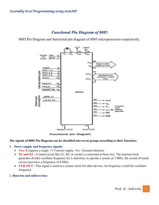
  • 1. Assembly level Programming using 8085MP Prof. K. Adisesha 1 Functional Pin Diagram of 8085 8085 Pin Diagram and functional pin diagram of 8085 microprocessor respectively. The signals of 8085 Pin Diagram can be classified into seven groups according to their functions. 1. Power supply and frequency signals: ➢ Vcc: It requires a single +5 V power supply, Vss : Ground reference. ➢ X1 and X2 : A tuned circuit like LC, RC or crystal is connected at these two. The internal clock generator divides oscillator frequency by 2, therefore, to operate a system at 3 MHz, the crystal of tuned circuit must have a frequency of 6 MHz. ➢ CLK OUT : This signal is used as a system clock for other devices. Its frequency is half the oscillator frequency. 2. Data bus and address bus:
  • 2. Assembly level Programming using 8085MP Prof. K. Adisesha 2 ➢ AD0 to AD7 : The 8 bit data bus (D0 – D7) is multiplexed with the lower half (A0 – A7) of the 16 bit address bus, These lines are used as a bi-directional data bus. ➢ A8 to A15 : The upper half of the 16 bit address appears on the address lines A8 to A15. These lines are exclusively used for the most significant 8 bits of the 16 bit address lines. 3. Control bus ➢ A) ALE (Address Latch Enable): We, know that AD0 to AD7 lines are multiplexed and the lower half of address (A0 – A7) is available only during T1 of the machine cycle. This lower half of address is also necessary during T2 and T3 of machine cycle to access specific location in memory or I/O port. ➢ B) RD and WR: These signals are basically used to control the direction of the data flow between processor and memory or I/O device/port. A low on RD indicates that the data must be read from the selected memory location or I/O port via data bus. A low on WR indicates that the data must be written into the selected memory location or I/O port via data bus. ➢ C) IO/M, S0 and S1: IO/M indicates whether I/O operation or memory operation is being carried out. S1 and S0 indicate the type of machine cycle in progress. ➢ D) READY: It is used by the microprocessor to sense whether a peripheral is ready or not for data transfer. If not, the processor waits. It is thus used to synchronize slower peripherals to the microprocessor. 4. Interrupt signals ➢ The 8085 Pin Diagram has five hardware interrupt signals: RST 5.5, RST 6.5, RST 7.5, TRAP and INTR. The microprocessor recognises interrupt requests on these lines at the end of the current instruction execution. ➢ The INTA (Interrupt Acknowledge) signal is used to indicate that the processor has acknowledged an INTR interrupt. 5. Serial I/O signals ➢ SID (Serial I/P Data): This input signal is used to accept serial data bit by bit from the external device. ➢ SOD (Serial O/P Data) : This is an output signal which enables the transmission of serial data bit by bit to the external device. 6. DMA signals ➢ A) HOLD: This signal indicates that another master is requesting for the use of address bus, data bus and control bus. ➢ B) HLDA: This active high signal is used to acknowledge HOLD request. 7. Reset signals: A low on this pin ➢ Sets the program counter to zero (0000H). ➢ Tri-states the data bus, address bus and control bus. On reset, the PC sets to 0000H which causes the 8085 Pin Diagram to execute the first instruction from address 0000H. The power-on reset circuit can be used to ensure execution of first instruction from address 0000H. RESET OUT: This active high signal indicates that processor is being reset. This signal is synchronized to the processor clock and it can be used to reset other devices connected in the system
  • 3. Assembly level Programming using 8085MP Prof. K. Adisesha 3 8085 Architecture 8085 is an 8-bit microprocessor designed by Intel in 1977 using NMOS technology. It has the following configuration – ➢ 8-bit data bus ➢ 16-bit address bus, which can address upto 64KB ➢ A 16-bit program counter ➢ A 16-bit stack pointer ➢ Six 8-bit registers arranged in pairs: BC, DE, HL ➢ Requires +5V supply to operate at 3.2 MHZ single phase clock
  • 4. Assembly level Programming using 8085MP Prof. K. Adisesha 4 8085 Microprocessor – Functional Units 8085 consists of the following functional units – Accumulator It is an 8-bit register used to perform arithmetic, logical, I/O & LOAD/STORE operations. It is connected to internal data bus & ALU. Arithmetic and logic unit As the name suggests, it performs arithmetic and logical operations like Addition, Subtraction, AND, OR, etc. on 8-bit data. General purpose register There are 6 general purpose registers in 8085 processor, i.e. B, C, D, E, H & L. Each register can hold 8-bit data. These registers can work in pair to hold 16-bit data and their pairing combination is like B-C, D-E & H-L. Program counter It is a 16-bit register used to store the memory address location of the next instruction to be executed. Microprocessor increments the program whenever an instruction is being executed, so that the program counter points to the memory address of the next instruction that is going to be executed. Stack pointer It is also a 16-bit register works like stack, which is always incremented/decremented by 2 during push & pop operations. Temporary register It is an 8-bit register, which holds the temporary data of arithmetic and logical operations Flag register It is an 8-bit register having five 1-bit flip-flops, which holds either 0 or 1 depending upon the result stored in the accumulator. These are the set of 5 flip-flops – ➢ Sign (S) ➢ Zero (Z) ➢ Auxiliary Carry (AC) ➢ Parity (P) ➢ Carry (C) Its bit position is shown in the following table –
  • 5. Assembly level Programming using 8085MP Prof. K. Adisesha 5 Instruction register and decoder It is an 8-bit register. When an instruction is fetched from memory then it is stored in the Instruction register. Instruction decoder decodes the information present in the Instruction register. Timing and control unit It provides timing and control signal to the microprocessor to perform operations. Following are the timing and control signals, which control external and internal circuits – ➢ Control Signals: READY, RD’, WR’, ALE ➢ Status Signals: S0, S1, IO/M’ ➢ DMA Signals: HOLD, HLDA ➢ RESET Signals: RESET IN, RESET OUT Interrupt control As the name suggests it controls the interrupts during a process. When a microprocessor is executing a main program and whenever an interrupt occurs, the microprocessor shifts the control from the main program to process the incoming request. After the request is completed, the control goes back to the main program. There are 5 interrupt signals in 8085 microprocessors: INTR, RST 7.5, RST 6.5, RST 5.5, TRAP. Serial Input/output control It controls the serial data communication by using these two instructions: SID (Serial input data) and SOD (Serial output data). Address buffer and address-data buffer The content stored in the stack pointer and program counter is loaded into the address buffer and address-data buffer to communicate with the CPU. The memory and I/O chips are connected to these buses; the CPU can exchange the desired data with the memory and I/O chips. Address bus and data bus Data bus carries the data to be stored. It is bidirectional, whereas address bus carries the location to where it should be stored and it is unidirectional. It is used to transfer the data & Address I/O devices.
  • 6. Assembly level Programming using 8085MP Prof. K. Adisesha 6 Program List 1. Assembly level program to exchange two 16-bit numbers 2. Assembly level program to addition two 8-bit numbers 3. Assembly level program to subtract two 8-bit numbers 4. Assembly level program to addition two 16-bit numbers 5. Assembly level program to subtract two 16-bit numbers (x>y) 6. Assembly level program to convert hexadecimal to BCD 7. Assembly level program to find 1’s compliment 16-bit number 8. Assembly level program to find whether the given number is positive negative or zero 9. Assembly level program to generate Fibonacci series 10.Assembly level program to square of hexadecimal number 11.Assembly level program to addition of n-byte numbers 12.Assembly level program to addition of two n-byte numbers 13.Assembly level program to implement block transfer 14.Assembly level program to implement block exchange 15.Assembly level program to find largest of two numbers 16.Assembly level program to find the largest of n-numbers 17.Assembly level program to find the smallest of 2-numbers 18.Assembly level program to find the smallest of n-numbers 19.Assembly level program to sort the array of numbers in ascending order 20.Assembly level program to multiplication of two decimal numbers
  • 7. Assembly level Programming using 8085MP Prof. K. Adisesha 7 1) PROGRAM TO EXCHANGE TWO 16 BIT NUMBERS Address Hex-code Label Opcode Operand Comments 8000 2A,00, F0 LHLD F000 H Load memory from specified locations. 8003 EB XCHG Exchange contents of HL & DE pairs. 8004 2A,00, F1 LHLD F100 H Load memory from specified locations. 8007 22,00, F0 SHLD F000 H Store memory to specified locations. 800A EB XCHG Exchange contents of HL & DE pairs. 800B 22,00, F1 SHLD F100H Store memory to specified locations. 800E 76 HLT Halt INPUT (Before execution) F001 ; F000 12 ; AB F101 ; F100 3C ; DE OUTPUT (After execution) F001; F000 3C ; DE F101 ; F100 12 ; AB
  • 8. Assembly level Programming using 8085MP Prof. K. Adisesha 8 2) PROGRAM TO ADDITION TWO 8 BIT NUMBERS Address Hex-code Label Opcode Operand Comments 8000 3E, XX MVI A, XX Move immediately to A, XX 8002 06, YY MVI B, YY Move immediately to B, YY 8004 80 ADD B Add A=A+B 8005 32, 00, F0 STA F000 H Store contents of A in specified location 8008 D2, 10, 80 JNC AHEAD1 Jump on no carry to Ahead1 800B 3E, 01 MVI A,01 H Move immediately to A, 01h 800D C3, 12, 80 JMP AHEAD2 Unconditional Jump to Ahead2 8010 3E, 00 AHEAD1 MVI A, 00 H Move immediately to A, 00h 8012 32, 01, F0 AHEAD2 STA F001 Store contents of A in specified location 8015 76 HLT Halt INPUT (Before execution) XX ; YY 20 ; 10 XX ; YY 2B : FA OUTPUT (After execution) F001 ; F000 00 30 F001 ; F000 01 : 25
  • 9. Assembly level Programming using 8085MP Prof. K. Adisesha 9 3) PROGRAM TO SUBTRACT TWO 8 BIT NUMBERS Address Hex-code Label Opcode Operand Comments 8000 3E,XX MVI A, XX Move immediately to A, XX 8002 06, YY MVI B, YY Move immediately to B, YY 8004 80 SUB B Subtract A=A-B 8005 32, 00, F0 STA F000 H Store contents of A in specified location 8008 D2, 10, 80 JNC AHEAD1 Jump on no carry to Ahead1 800B 3E, 01 MVI A,01 H Move immediately to A, 01h 800D C3, 12, 80 JMP AHEAD2 Unconditional Jump to Ahead2 8010 3E, 00 AHEAD1 MVI A, 00 H Move immediately to A, 00h 8012 32, 01, F0 AHEAD2 STA F001 Store contents of A in specified location 8015 76 HLT Halt INPUT (Before execution) XX; YY 20 ; 10 XX; YY 2B : FA OUTPUT (After execution) F001; F000 00 10 F001 ; F000 01 : 31
  • 10. Assembly level Programming using 8085MP Prof. K. Adisesha 10 4) PROGRAM TO ADDITION TWO 16 BIT NUMBERS Address Hex-code Label Opcode Operand Comments 8000 AF XRA A Clear accumulator & Flags 8001 2A, 00, F0 LHLD F000 Load memory from specified locations. 8004 EB XCHG Exchange contents of HL & DE pairs. 8005 2A, 00, F1 LHLD F100 Load memory from specified locations. 8008 19 DAD D Add the contents of HL & DE 8009 22, 00, F2 SHLD F200 Store memory to specified locations. 800C D2, 10, 80 JNC AHEAD Jump on no carry to AHEAD 800F 3C INR A Increment contents of Accumulator by 1 8010 32, 02, F2 AHEAD STA F202 Store memory to specified locations. 8013 76 HLT Halt INPUT (Before execution) F001: F000 (X) 10 : 20 F101: F100 (Y) 30 : 40 F001: F000 (X) 4A : 2C F101: F100 (Y) ED : 5B OUTPUT (After execution) F202:F201: F200 (X+Y) 01 : 40 : 60 F202:F201: F200 (X+Y) 01 : 37 : 87
  • 11. Assembly level Programming using 8085MP Prof. K. Adisesha 11 5) PROGRAM TO SUBTRACT TWO 16 BIT NUMBERS (X>Y) Address Hex-code Label Opcode Operand Comments 8000 2A, 00, F0 LHLD F000 Load memory from specified locations. 8003 EB XCHG Exchange contents of HL & DE pairs. 8004 2A, 00, F1 LHLD F100 Load memory from specified locations. 8007 7D MOV A, L Move content of [L] to [A] 8008 93 SUB E Subtract [E] from [A] 8009 32, 00, F2 STA F200 Store memory to specified locations. 800C 7C MOV A, H Move content of [H] to [A] 800D 9A SBB D Subtract with borrow [D] from [A] 800E 32,01, F2 STA F201 Store memory to specified locations. 8011 76 HLT Halt INPUT (Before execution) F001: F000 (X) FA : 2C F101: F100 (Y) BD : 5B OUTPUT (After execution) F201: F200 (X-Y) 3C : D1
  • 12. Assembly level Programming using 8085MP Prof. K. Adisesha 12 6) Assembly level Program to convert Hexadecimal to BCD Address Hex Code Label Opcode Operand Comments 9000 21,00,80 LXI H,8000H Initialise HL register pair as memory point to load data byte 9003 0E,00 MVI C,00H Clear C to register to store carry 9005 46 MOV B, M Move the hex data to B register 9006 AF XRA A Clear accumulator 9007 C6,01 UP ADI 01 H Add 1 to accumulator 9009 27 DAA Decimal Adjust Accumulator covert hexadecimal to BCD 900A D2,0E,90 JNC LOOP If no carry, jump to the specified memory location 900D 0C INR C If there is a carry, increment C register by 1 900E 05 LOOP DCR B Decrement B by 1 900F C2,07,90 JNZ UP If counter is not zero, go to the specified lable UP 9012 32,01,80 STA 8001H Store the BCD number in memory location 8001H 9015 79 MOV A, C Move the carry to the accumulator 9016 32,02,80 STA 8002H Store the carry in the memory location 8002H 9019 76 HLT Terminate program execution INPUT (Before execution) 8000 (X) : 2F H 8000 (Y) : 20 H OUTPUT (After execution) 8001: 47 D, 8002: 00 D 8001: 20 D, 8002: 00 D
  • 13. Assembly level Programming using 8085MP Prof. K. Adisesha 13 7) Assembly level Program to find 1’s compliment 16-Bit number Address Hex-Code Label Opcode Operand Comments 9000 21,00,85 LXI H,8500H Initialise HL register pair as memory point to load data byte 9003 7E MOV A, M Move the lower data byte to accumulator 9004 2F CMA Complement the lower data byte 9005 32,02,80 STA 8502 H Store the result in memory location 8502 H 9008 23 INX H Increment the pointer to get the higher data byte 9009 7E MOV A, M Move the higher data byte to the accumulator 900A 2F CMA Complement the higher data byte 900E 32,03,85 STA 8503 H Store the result in memory location 8503 H 900E 76 HLT Terminate program execution INPUT (Before execution) 8501: 8500 8B H : 36 H 8501: 8500 28 H : AB H OUTPUT (After execution) 8502: 8503 C9 H : 74 H 8502: 8503 54 H : E7 H
  • 14. Assembly level Programming using 8085MP Prof. K. Adisesha 14 8) Assembly level Program to find whether the given number is positive negative or zero Address Hex- Code Label Opcode Operand Comments 8500 21,00,82 LXI H,8100H Setup HL as memory pointer with memory address 8200H 8503 7E MOV A, M Get the data byte as accumulate 8504 E6, FF ANI FFH AND accumulator context with FFH 8506 CA, 0F,85 JZ ZERO Jump on zero, if the result is zero jump to specific loop 8509 FA,14,85 JM NEGATIVE Jump on minus, if D, byte is 1, jump to specified loop 850C F2,19,85 JP POSITIVE If result is zero, 850F 3E,00 ZERO MVI A,00H Move 00H to accumulator 8511 C3,1B,85 JMP LOOP Jump to loop 8514 3E, FF NEGATIVE MVI A, FFH Move FF to accumulator 8516 C3,1B,85 JMP LOOP Jump to loop 8519 3E,01 POSITIVE MVI A,01H Move 01 to accumulator 851B 32,01,82 LOOP STA 8101H Store the contents of accumulator to specified address 851E 76 HLT Terminate program execution INPUT (Before execution) 8100: 74 H 8100: 94 H OUTPUT (After execution) 8101: 01 H 8101: FF H
  • 15. Assembly level Programming using 8085MP Prof. K. Adisesha 15 9) Assembly level Program to generate Fibonacci series Address Hex-Code Label Opcode Operand Comments 8500 0E,0A MVI C,0AH Setup a counter by loading count 0AH to C register 8502 21,00,81 LXI H,8100H Setup HL as memory pointer with memory address 8100H 8505 7E MOV A, M Get 00H to accumulator 8506 23 INX H Increment the pointer to get next data 8507 56 MOV D, M Get 01H to D register 8508 82 LOOP ADD D Add content of accumulator with content of D register 8509 27 DAA Decimal adjust accumulator 851A 23 INX H Increment pointer to store sum 851B 77 MOV M, A Move accumulator content to next location 851C 7A MOV A, D Move D registers to accumulate 851D 56 MOV D, M Move content of memory location to D register 851E 0D DCR C Decrement C to register by 1 850F C2,08,85 JNZ LOOP If counter value is not zero, go to the label Loop 8512 76 HLT Terminate program execution INPUT (Before execution) 8100: 00 H, 8101: 01 H OUTPUT (After execution) 8100 -to - 810A: 00H, 01H, 02H, 03H, 05H, 0DH, 15H, 22H, 37H, 59H
  • 16. Assembly level Programming using 8085MP Prof. K. Adisesha 16 10) Assembly level Program to square of Hexadecimal number Address Hex-Code Label Opcode Operand Comments 8000 21,00,90 LXI H,9000H Register pair HL is loaded with memory location 9000H 8003 3E,00 H MVI A,00H Clear accumulator to avoid addition of junk values and to store the correct result 8005 57 MOV D, A Clear register D to save carry 8006 4E MOV C, M Copy the contents of memory M to register C and the value in register C is used as a counter 8007 86 UP ADD M The contents of M is repeatedly add with contents of accumulator A until the counter is 0 8008 D2, 0C, 80 JNC LOOP If no carry jump to label LOOP 800B 14 INR D If carry increment register D by 1 850C 0D LOOP DCR C Decrement the counter(reg C) by 1 800D C2, 07, 80 JNZ UP If the counter value is not equal to zero< go back to the label UP 8010 32, 00, 91 STA 9100H Store the content of the accumulator (result of square of a number) in 9100H memory location 8013 7A MOV A, D Move the carry to the accumulator 8014 32, 01, 91 STA 9101H Store the carry in 9101H memory location 8017 76 HLT Terminate the program execution INPUT (Before execution) 9000: 02 H 9000: 04 H OUTPUT (After execution) 9100: 9101 04 H: 00 H 9100: 9101 10 H: 00 H
  • 17. Assembly level Programming using 8085MP Prof. K. Adisesha 17 11) Assembly level Program to addition of N-byte numbers Address Hex-Code Label Opcode Operand Comments 8000 0E, 06H MVI C,06H Set up C reg, counter value 06H bytes. 8002 AF XRA A Clear accumulator to avoid addition of junk values and to store the correct result 8003 47 MOV B, A Clear register B to save carry 8004 21,00,81 LXI H,8100H Register pair HL is loaded with memory location 8100H 8007 86 UP ADD M The contents of memory M is repeatedly add with the contents of accumulator A until the counter is 0 8008 D2,0C,80 JNC LOOP If no carry jump to the label LOOP 800B 04 INR B If carry increment register D by 1 800C 23 LOOP INX H Increment memory pointer to store next byte to add 800D 0D DCR C Decrement counter (register C) by 1 800E C2,07,80 JNZ UP If the counter value is not equal to zero, go back to the label UP 8011 32,00,91 STA 8200H Store the content of the accumulator (result of square of a number) in 8200H memory location 8014 78 MOV A, B Move the carry to the accumulator 8015 32,01,82 STA 8201H Store the carry in 8201H memory location 8018 76 HLT Terminate the program execution INPUT (Before execution) 8100 -to - 8105: 25H, 31H, 64H, 80H, 15H, 42H OUTPUT (After execution) 8200- 91H (Sum), 8201- 01H(Carry)
  • 18. Assembly level Programming using 8085MP Prof. K. Adisesha 18 12) Assembly level Program to addition of TWO N-byte numbers Address Hex-Code Label Opcode Operand Comments 8000 21, 00, 81 LXI H, 8100H Set up HL as memory pointer source memory 8003 11, 00, 82 LXI D, 8200 H Setup DE as a memory pointer for the destination memory 8006 06, 04H MOV C, 04H Setup C as a byte counter to transfer data to new memory location 8008 AF XRA A Clear Accumulator 8009 1A Next LDAX D Get the data byte od 2nd number to Acc. 800A 8E ADC M Add 1st and 2nd number with carry 800B 77 MOV M, A Save the sum in memory pointer by HL 800C 23 INX H Increment memory pointer HL to store next byte to add 800D 13 INX D Increment memory pointer DE to store next byte to add 800E 0D DCR C Decrement counter (register C) by 1 800F C2,09,08 JNZ Next Go to pointer next if counter is not zero 8012 3E, 00H MVI A,00H Clear accumulator to save carry 8014 17 RAL Move the carry to the accumulator 8015 77 MOV M, A Store the carry in 8201H memory location 8016 76 HLT Terminate the program execution INPUT (Before execution) 8100 -to - 8103: 35H, 45H, 55H, 65H 8200 -to - 8203: 29H, 14H, 68H, B9H OUTPUT (After execution) 8100 -to-8103: 5EH, 59H, BDH, 1EH (Sum), 8104- 01H(Carry)
  • 19. Assembly level Programming using 8085MP Prof. K. Adisesha 19 13) Assembly level Program to implement block transfer Address Machine code Label Opcode Operand Comments 9000 21, 00, 80 LXI H, 8000H Set up HL as memory pointer source memory 9003 11, 00, 81 LXI D, 8100 H Setup DE as a memory pointer for the destination memory 9006 06, 0A MOV B, 0AH Setup B as a byte counter to transfer ten bytes of data to new memory location B is loaded with 0AH 9008 7E NEXT MOV A, M Move the data byte of source memory to accumulator 9009 12 STAX D Transfer the data byte to the destination memory 900A 23 INX H Increment the source memory pointer to get to the next byte 900B 13 INX D Increment the memory pointer to transfer next data byte 900C 05 DCR B Decrement the counter by 1, if one data byte is transferred 900D C2, 08, 90 JNZ NEXT If counter is not zero, go back to NEXT to transfer next data byte 9010 76 HLT Terminate program execution INPUT (Before execution) 8000 -to - 8009: 10H, 20H, 30H, 40H, 50H, 60H.70H, 80H, 90H, 0AH OUTPUT (After execution) 8100 -to - 8109: 10H, 20H, 30H, 40H, 50H, 60H.70H, 80H, 90H, 0AH
  • 20. Assembly level Programming using 8085MP Prof. K. Adisesha 20 14) Assembly level Program to implement block exchange Address Hex-code Label Opcode Operand Comments 9000 06, 05H MVI B,0AH Setup B as a byte counter to exchange two 16-bit numbers B is loaded with 0AH 9002 21, 50, 80 LXI H, 8000H Setup HL as a memory pointer for 8000H memory location 9005 11, 70, 80 LXI D, 8070 Setup DE as a memory pointer for 8100H memory location 9008 1A loop LDAX D Move the contents of memory pointer specified by the DE register pair to accumulator 9009 4F MOV C, A Save the contents of accumulator in C register 900A 7E MOV A, M Move the data byte of memory pointer specified by the HL register pair to accumulator 900B 12 STAX D Transfer the data byte of HL register pair memory pointer to DE register pair memory pointer 900C 71 MOV M, C Transfer the data byte of DE register pair memory pointer to the HL register pair memory pointer 900D 23 INX H Increment the source memory pointer to transfer to next data byte 900E 13 INX D Increment the destination memory pointer to transfer next data byte 901F 05 DCR B Decrement counter by 1, if one data byte is exchanged 9010 C2, 08, 90 JNZ loop If counter is not zero, go back to repeat to exchange next data byte 9013 76 HLT Terminate program execution INPUT (Before execution) 8000 -to - 8009: 11H, 22H, 33H, 44H, 55H, 66H.77H, 88H, 99H, AAH 8100 -to - 8109: 10H, 20H, 30H, 40H, 50H, 60H.70H, 80H, 90H, 0AH OUTPUT (After execution) 8000 -to - 8009: 10H, 20H, 30H, 40H, 50H, 60H.70H, 80H, 90H, 0AH 8100 -to - 8109: 11H, 22H, 33H, 44H, 55H, 66H.77H, 88H, 99H, AAH
  • 21. Assembly level Programming using 8085MP Prof. K. Adisesha 21 15) Assembly level Program to find largest of two numbers Address Hex code Label Opcode Operand Comment 9000 21, 00,85 LXI H, 8000H Setup HL as memory pointer with memory address 8000H to store 1st data byte 9003 7E MOV A, M Moves the data byte stored in 8000H memory location addressed by H-L register pair to accumulator 9004 23 INX H Increments the memory pointer by 1(8051) to store the 2nd data byte 9005 BE CMP M Compares the two numbers 9006 D2,0A,90 JNC NEXT Of no carry larger number is in accumulator then go NEXT 9009 7E MOV A, M If carry, the larger number in 8051H memory location then move the larger number to accumulator 900A 32,03,85 NEXT STA 8102H Stores the larger number in 8502H memory location. 900D 76 HLT Stop processing INPUT (Before execution) 8100 -25H - 8101: 31H OUTPUT (After execution) 8102- 31H (Largest number)
  • 22. Assembly level Programming using 8085MP Prof. K. Adisesha 22 16) Assembly level Program to find the largest of N-numbers Address Hex-Code Label Opcode Operand Comment 9000 0E, 0AH MVI C,0AH Setup C-register with a counter value 0AH to find the largest of ten data bytes 9002 21, 00, 85 LXI H, 8500H Setup HL as memory pointer with memory address 8500H 9005 7E MOV A, M Moves the data byte stored in 8500H memory location to accumulator 9006 0D DCR C Decrement counter by 1, if the 1st byte is loaded to accumulator 9007 23 REPEAT INX H Increments the memory pointer by 1 to store the next data byte 9008 BE CMP M Compares two numbers 9009 D2, 0D,90 JNC NEXT If no carry larger number is in accumulator go to NEXT 900C 7E MOV A, M If carry, the larger number is in memory pointer then move the larger number to accumulator 900D 0D NEXT DCR C Decrement the counter by 1, if one data byte is checked 900E C2, 07, 90 JNZ REPEAT If counter is not zero, go to loop repeat to find the largest of the remaining data bytes 9011 32, 00, 86 STA 8600H Store the largest in 8600H memory location 9014 76 HLT Stop processing INPUT (Before execution) 8500 -to - 8509: 10H, 20H, 30H, 40H, 50H, 60H.70H, 80H, 90H, A0H OUTPUT (After execution) 8600- A0H (Largest number)
  • 23. Assembly level Programming using 8085MP Prof. K. Adisesha 23 17) Assembly level Program to find the smallest of 2-numbers Address Hex-code Label Opcode Operand Comment 9000 21, 01,85 LXI H, 8501H Setup H as memory pointer with memory address 8051H to store 1st data byte 9003 7E MOV A, M Moves the data byte stored in 8051H memory location addressed by H-L register pair to accumulator 9004 23 INX H Increments the memory pointer by 1(8052H) to store the 2nd data byte 9005 BE CMP M Compares the two numbers 9006 DA,0A,90 JC NEXT If carry smaller number is in accumulator, then go to NEXT 9009 7E MOV A, M If no carry the smaller number in 8052H memory location then moves the smaller number to accumulator 900A 32, 00, 86 NEXT STA 8600H Stores the smaller number in 8503H memory location 900D 76 HLT Stop processing INPUT (Before execution) 8100 -25H - 8101: 31H OUTPUT (After execution) 8103- 25H (Smallest number)
  • 24. Assembly level Programming using 8085MP Prof. K. Adisesha 24 18) Assembly level Program to find the smallest of N-numbers Address Hex-code Label Opcode Operand Comments 9000 0E, 0AH MVI C,0AH Setup C-register with a counter value 0AH to find the largest of ten data bytes 9002 21, 00, 85 LXI H, 8500H Setup HL as memory pointer with memory address 8500H 9005 7E MOV A, M Moves the data byte stored in 8500H memory location to accumulator 9006 0D DCR C Increments the memory pointer by 1 to store the next data byte 9007 23 REPEAT INX H Increments the memory pointer by 1 to store the next data byte 9008 BE CMP M Compares the two numbers 9009 DA,0D, 90 JC NEXT If carry smaller number is in accumulator go to NEXT 900C 7E MOV A, M If no carry, the smaller number is in memory pointer then move the smaller number to accumulator 900D 0D NEXT DCR C Decrement the counter by 1, if one data byte is checked 900E C2, 07, 90 JNZ REPEAT If counter is not zero, go to loop repeat to find the smallest of the remaining data bytes 9011 32, 00, 86 STA 8600H Store the largest in 8600H memory location 9014 76 HLT Stop processing INPUT (Before execution) 8500 -to - 8509: A0H, 20H, 10H, 40H, 50H, 60H, 90H, 80H, 70H, 30H OUTPUT (After execution) 8600- 10H (Smallest number)
  • 25. Assembly level Programming using 8085MP Prof. K. Adisesha 25 19) Assembly level Program to sort the array of numbers in ascending order Address Hex-code Label Opcode Operand Comments 9000 16, 05h MVI D,05H Setup D-register as counter 1 with counter value 05H to arrange ten bytes of numbers in ascending order 9002 21, 00, 85 LOOP3 LXI H, 8500H Setup HL as memory pointer (M) with memory address 8500H 9005 0E, 05 MVI C,05H Setup C-register as counter 2 with a counter value 05H to arrange ten bytes of numbers in ascending order 9007 7E LOOP2 MOV A, M Moves the data byte stored in memory pointer to accumulator 9008 23 INX H Increment the memory pointer 1 9009 BE CMP M Compare the contents of memory pointer with accumulator contents 900A DA,12,90 JC LOOP1 If (A) < (M) jump to Loop1 otherwise exchange the contents of accumulator and memory pointer 900D 46 MOV B, M If (A) < (M) exchange the contents of memory pointer (M) and (M-1) 900E 77 MOV M, A Decrement by one if the content of (M- 1) < (m) 900F 2B DCX H 9010 70 MOV M,B 9011 23 INX H 9012 0D LOOP1 DCR C Decrement by one if the content of (M- 1) < (m) 9013 C2, 07, 90 JNZ LOOP2 If counter is not zero go back to Loop2 to keep smaller number in memory pointer 9016 15 DCR D Decrement the D-counter by one 9017 C2, 02, 90 JNZ LOOP3 If the counter is not zero go back to Loop3 to repeat the same operation to arrange the numbers in ascending order 901A 76 HLT End of program INPUT (Before execution) 8000 -to - 8009: 30H, 0AH, 10H, 60H, 90H, 40H.70H, 80H, 50H, 02H OUTPUT (After execution) 8100 -to - 8109: 10H, 20H, 30H, 40H, 50H, 60H.70H, 80H, 90H, 0AH
  • 26. Assembly level Programming using 8085MP Prof. K. Adisesha 26 20) Assembly level Program to multiplication of two decimal numbers Address Hex-code Label Opcode Operand Comments 9000 0E, 08D MVI C, XX D Get multiplied in C register 9002 16, 04D MVI D, YYD Get multiplied in D register 9004 AF XRA A Clear accumulator to save sum 9005 47 MOV B, A Clear B register to save generated carry 9006 81 LOOP ADD C Add multiplicand to accumulator 9007 27 DAA Adjust the sum for decimal value 9008 DA, 0C, 90 JNC LOOP1 If no carry go to Next 900B 04 INR B If carry B register is incremented by 1 900C 15 LOOP1 DCR D Decrement the D register by 1, if the multiplicand is added to accumulator once 900D C2, 06, 90 JNZ LOOP If multiplier is not zero, go to loop to add multiplicand again 9010 32, 00, 86 STA 8000H Stores the product in 8600 memory location 9013 78 MOV A, B Moves the contents of B register (carry contents) to accumulator 9014 32, 01,86 STA 8001H Stores the carry in 8601 memory location 9017 76 HLT Terminate program execution INPUT (Before execution) a) XX: YY 08 D: 04 D b) XX: YY 04 D: 02 D OUTPUT (After execution) 8001: 8000 00 D: 32 D 8001: 8000 00 D: 08 D