Booking open Available Pune Call Girls Koregaon Park 6297143586 Call Hot Ind...
17. seepage through anisotropic soil (1)
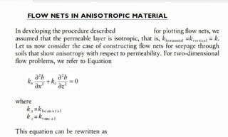
1. FLOW NETS I N A N I S O T R O P I C MATERIAL
In developing the procedure described for plotting flow nets, we
assumed that the permeable layer is isotropic, that is, krona =k,ate = k.
Let us now consider the case of constructing flow nets for seepage through
soils that show anisotropy with respect to permeability. For two-dimensional
flow problems, we refer to Equation
where
k , = k , o n t a l
k , = k e a t
This equation can be rewritten as
previously
:
(Ref. BM Das)
3. Substituting
which governs the
flow in isotropic soils and should represent two sets of orthogonal lines
in the x'z plane. The steps for construction of a flow net in an anisotropic
medium are as follows:
1. T
o plot the section of the hydraulic structure, adopt a vertical scale.
2. Determine /k./k, = lk a l % o a t
3. Adopt a horizontal scale such that
4. With the scales adopted in steps 1 and 3, plot the cross section of the
structure.
5. Draw the flow net for the transformed section plotted in step 4 in the
the expression of x' , we get
Above equation is same as Laplace eqn.
x dimension will be modified to x'.
4. I I C I H I A I H I I I d I ( O I I C IOI SCCpd4C L I 1 I O U 4 I I 1 O L I U p I K S U 1 I S ,
6. Calculate the rate of seepage as
Example
A dam section is shown in Figure 7.9a. The coefficients of permeability
of the permeable layer in the vertical and horizontal directions are
2 x 1 0 - a n d 4 10- mm/s, respectively. Draw a flow net and calculate
the seepage loss of the dam in m/(day·m).
Solution
From the given data
where, sqrt.(kx . kz) is the equvt permeability ke. Studemt is asked to derive it.
The above equation is same in form as derived for Isotropic Soil, except K is replaced by Ke.
5. . h] m e · l Advanced Soit Mechanics; Fifth Edition Nitro P
r
o - 6 X
File Convert Review Page Layout Forms Share Erase Protect Help login
U m
m
h T ./ a [! (
5
~ 5
A
c
[@Rotate·
3 ·l
I, tat Er beete
zoom
Select T
y
p
e Qui«Sign Request PD
F Combine T
o T
o Highlight nsert
[ 6t
r
a
ct
F
i
n
d A
d
d Customize
T
e
t Signature word D
e
l Note Tools
Tools Create Convert R
evi
ew P
a
g
e layout Document Favorite Tools
D
x
G
I cover •
£
I H
a
it T
i
l
e
I mute Page
l copyright Page
l Dedication
I contents
I Preface
[ Acknowledgments
I Author
a [] 1. soil aggregate, plasticity,
and classification
[ Advanced_Soit_Mechanics_Fifth_Edi.. X
k,
and h
2x10mm/s 1.728 m/day
•
•
k, =4x10mm/s = 3.456 m/day
10 m. For drawing the flow net,
8 [ 2 stresses and strains:
Horizontal
Elastic equilibrium
ffi [] 3 . stresses and
displacements I
n a soil mass:
Two-dimensional problems
8 []4. stresses and
displacements i
n a soil mass:
Three-dimensional problems
8 [ 5 pore w
a
t
e
r Pressure d
u
e
t
o undrained loading
ffi ] 6
. Permeability
a In7. seepage
a le. consolidation
8 [9. shear strength o
f soils
gen
a [ 1o. E
l
a
s
t
i
c settlement o
f
0 shallow foundations
z e [ 1 . consolidation settlement
I ◄ ◄ 298 03
2
1 O
F 7
3
5
► I o 0
II P Search
0 0 g a g + 213%
dimension is reduced by Sqrt.2
6. I0 m
Permeable
layer 12.5 m
(a) Impermeable layer
10 m
-
'
1.
0 :
f
'
f
'
,
,
'
,
'
,
' ' '
f
'
1.
0
' '
'
f
' '
f
'
'
I 05
'
'
' '
$
' '
'
' ' ' ' ' ' '
'
Horizontal scale = 12.5 V-17.68 m
(
b
) Vertical scale = 12.5 m
fi
g
u
r
e 7.9 Construction of flow net under a dam: (a) section of the dam; (b) flow net.
7. On the basis of this, the damsection is replotted, and the tlow net drawn
as in Egure 79h. The rate of seepage is given by q = Jk,k,h(NIN).
From Figure7.9b, N
, = 8 and N
, = 2.5 (the lowermost flow channel has
a width-to-length ratio of 0.5). So
q =4(1.728)63.456)010)02.5/8) = 7.637 m'/(day ·m)
Example 7.4
A single row of sheet pile structure is shown in Figure 7.10a. Draw a
flow net for the transformed section. Replot this flow net in the natu
ral scale also. The relationship between the permeabilities is given as
k, = 6k_.
Solution
For the transformed section
· e
k,
Horizontal dimension actual dimension
actual horizontal dimension.
8. •
1 5 m
4 m
+
2
0 m
(
a
) Impermeable l
a
y
e
r
(
b
)
==a
- -
Vertical scale
,
IO m
,
-
, ,
'
'
,
'
+
' ' '
f
f
'
'
Horizontal scale =
'
'
' ' 1 o » 6=24.5 m
f
f
' ' '
f
'
f
' '
Impermeable layer
9. '
'
---
---
--
-----
--- ---
.
----
-
-
,
10 m
(
c
) Scale
Fi
g
u
r
e 740 Flow net construction in anisotropic soil: (a) sheet pile structure; (
b
) flow
net in transformed scale; (
c
) flow net in natural scale.
Ke = sqrt. (Kx.Kz) .... prove it.
In previous slide obtain h, z and hp at points A, B and C
HT:
![l
i
Let x'=/k./Ik,x, then
[x' is the transformed coordinate]](data:image/gif;base64,R0lGODlhAQABAIAAAAAAAP///yH5BAEAAAAALAAAAAABAAEAAAIBRAA7)