Spe yp monthly session hydraulic fracturing technology - april 2021
Tube Hydroforming of Thinwall CRES
1. Tube Hydroforming of Thinwall CRES Tubing
John Ogden, Weldmac Manufacturing Company, El Cajon, CA
Abstract
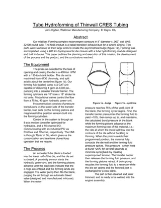
Our mission: Forming complex reconvergent contours in 8” diameter x .063” wall UNS
32100 round tube. The final product is a radial transition exhaust duct for a turbine engine. Two
parts were siamesed at their large ends to create the asymmetrical bulge (figure 1a). Forming was
accomplished using a 400 ton hydropress for die closure with a tube hydroforming module designed
and built in-house. This paper outlines the planning and execution of this mission, the development
of the process and the product, and the conclusions reached.
The Equipment
The press we selected for the task of
opening and closing the die is a 400-ton HPM
with a 130-ton blank holder. The die set is
machined from 4130 chromoly, and split
axially about the centerline (figure 1b). Our
forming fluid (water) pump is a CAT unit
capable of delivering 4 gpm at 2,000 psi.,
pumping into a oil/water transfer barrier. The
forming cylinders are 10” bore x 18” stroke tie
rod units. Proportional valves control the flow
from a 75 hp, 40 gpm hydraulic power unit.
Instrumentation consists of pressure
transducers on the water side of the transfer
barrier, load cells on the forming pistons and
magnetostrictive position sensors built into
the forming cylinders.
Control of the system is through an
8-axis motion controller optimized for
hydraulics, and a 16-channel I/O,
communicating with an industrial PC via
Profibus and Ethernet, respectively. The HMI
is through Think ‘n’ Do, which gives us the
customization and real-time closed-loop
operation that we require.
The Process
An annealed tube blank is loaded
into the lower half of the die, and the die set
is closed. A proximity sensor starts the
hydraulic power unit, and the forming pistons
advance until the load cells indicate that the
o-rings are entered and the forming lands are
engaged. The water pump then fills the blank,
purging the air through an automatic bleed
valve (designed and manufactured in-house).
When the water
pressure reaches 75% of the yield point of
the blank, the forming cycle begins. First, the
transfer barrier pressurizes the forming fluid to
yield +10%, then ramps up to, and maintains,
the calculated burst pressure of the blank
while the forming pistons advance at the
maximum forming rate of the material, i.e.:
the rate at which the metal will flow into the
contours of the die without buckling or
thinning. When the pistons reach their
programmed position, the material fully
contacts the die wall and the forming fluid
pressure spikes. This pressure is then held
at burst +25% for several seconds to
minimize springback by creating
superimposed tension. The transfer barrier
then releases the forming fluid pressure, and
the forming pistons retract. A drain pump
recycles the forming fluid to a reservoir while
the die set opens and the finished part is
exchanged for a new blank.
The part is then cleaned and laser
trimmed, and is ready to be welded into the
engine assembly.
Figure 1a – bulge Figure 1b – split line
2. The Result
Following a relatively short
development phase, we were able to produce
a finished part with an 80% circumferential
increase, yet only 9% thinning in the walls.
An interesting note: we actually experienced
~5% thickening in the walls closest to the
forming pistons, due to friction as the die
contact area increased at the end of the
forming stroke.
Process parameters such as feed
rate, feed distance and forming fluid pressure
exhibited a narrow band of acceptable
performance (± 5%), and once outside this
range, integrity of the blank was
compromised. While slight buckling could be
remedied with increased internal pressure,
the other failure mode, rupture, was
permanent and rather dramatic! The inherent
safety of using an incompressible forming
fluid became readily apparent, as the initial
deluge from a ruptured blank possessed
pressure, but no real volume, and was easily
handled by the vents in the die set.
The HMI allowed us to reduce the
control system to 3 (virtual) buttons and an E-
stop, which nearly eliminated the need for
operator training. Cycle time can be reduced
in the forming and dwell areas, but is largely
dependant upon the fill time.
Conclusions
The forming pressure requirements of
this process are a function of the section of
the blank, and the configuration of this part
lends itself to production using readily
available components at standard industrial
pressures. The radial asymmetry of the part
presented a challenge from the material flow
standpoint, but the bilateral symmetry
facilitated the construction of the die set.
Friction cannot be overlooked when
planning a hydroforming project which
includes any radii (internal or external) of 6t or
less. Extreme pressure, water soluble
lubricants are essential to acceptable part
quality, secondary operations, and low
environmental impact. Our analysis of various
formulations is ongoing.
The (varying) quality of the anneal
proved to be a wildcard in the consistency of
the production run, while variations in wall
thickness produced effects strictly in
accordance with our mathematical model.
The strain-hardening propensity of
this alloy can be minimized by achieving a
balance between end-feed and radial
expansion, while that of other aerospace
alloys (UNS N06625, in particular) may
require a more sophisticated approach. Many
alloys warrant further investigation in
response to the increasing demand for
aerospace components possessing the native
qualities of tubular hydroformed parts, i.e.:
complex contours with single-piece
construction and low residual stress.
Overall, we have found the tube
hydroforming process to be an economical
alternative to the previous manufacturing
method, which was multi-piece welded
construction. It is predictable, controllable,
automatable, and suitable for production
when applied to complex parts in large
diameter thinwall tubing.