Presented October 13, 2010 by Greg McMillan as on-line demo/seminar. Video recording available at: http://www.screencast.com/users/JimCahill/folders/Public
Interactive Opportunity AssessmentDemo and Seminar (Deminar) Series for Web Labs – PID Deadtime Compensation Oct 13, 2010 Sponsored by Emerson, Experitec, and Mynah Created by Greg McMillan and Jack Ahlers www.processcontrollab.com Website - Charlie Schliesser (csdesignco.com)
2.
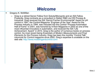
Welcome Gregory K.McMillan Greg is a retired Senior Fellow from Solutia/Monsanto and an ISA Fellow. Presently, Greg contracts as a consultant in DeltaV R&D via CDI Process & Industrial. Greg received the ISA “Kermit Fischer Environmental” Award for pH control in 1991, the Control Magazine “Engineer of the Year” Award for the Process Industry in 1994, was inducted into the Control “Process Automation Hall of Fame” in 2001, was honored by InTech Magazine in 2003 as one of the most influential innovators in automation, and received the ISA “Life Achievement Award” in 2010. Greg is the author of numerous books on process control, his most recent being Essentials of Modern Measurements and Final Elements for the Process Industry. Greg has been the monthly “Control Talk” columnist for Control magazine since 2002. Greg’s expertise is available on the web site: http://www.modelingandcontrol.com/
3.
The TopTen Signs You are Ready for a Hawaiian Vacation (10) You give your boss the “hang loose” hand gesture (9) You day dream about hula dancers in hardhats (8) Your cubicle has a mosquito net with tropical sounds (7) You bring a kayak to the company’s waste pond (6) You ask “where is the company’s pupu stand”? (5) You tell your secretary she is wearing a nice muumuu (4) You play a ukulele in your office (3) You show up to a meeting in a Hawaiian shirt, shorts and sandles (2) You start answering your phone saying "Aloha" And the Number 1 sign:
4.
The TopTen Signs You are Ready for a Hawaiian Vacation (1) You wear a snorkeling mask instead of glasses
5.
Introduction The firstdeadtime compensator to be significantly used in the process industry was the Smith Predictor (1957) The controller output is passed through a multiplier (process gain), filter (process time constant), and deadtime (process deadtime) to create a model of the process with deadtime that is subtracted from PV The controller output is also passed through just a multiplier (process gain) and filter (process time constant) to create a model of the process without deadtime that is added to PV The user must adjust process gain, process time constant, and process deadtime The user and PID sees a PV without deadtime (special faceplate is needed to see actual PV) Academic deadtime compensators are rarely used in industry The simplest deadtime compensator inserts a deadtime block in the BK_CAL path (external reset) between the AO and PID blocks Works for positive feedback integral mode (e.g. DeltaV) but not conventional integral mode (e.g. PRoVOX) Dynamic Reset Limit must be enabled (good idea anyway for slow valves and slow secondary loops) The user only needs to adjust the deadtime The user and PID sees the actual PV The external reset deadtime compensator is less sensitive than Smith Predictor to model errors Myths exposed in this Deminar ! Deadtime is eliminated from loop Control is faster for existing tuning settings Compensator works better for loops dominated by a large deadtime An underestimate of the deadtime leads to instability (contrary to PID tuning calcs) An overestimate of the deadtime leads to sluggish response and greater stability (contrary to PID tuning calcs)
6.
Delay “ Withoutdeadtime I would be out of a job” Fundamentals A more descriptive name would be total loop deadtime . The loop deadtime is the amount of time for the start of a change to completely circle the control loop and end up at the point of origin. For example, an unmeasured disturbance cannot be corrected until the change is seen and the correction arrives in the process at the same point as the disturbance. Process deadtime offers a continuous train of values whereas digital devices and analyzers offer non continuous data values at discrete intervals, these delays add a phase shift and increase the ultimate period (decrease natural frequency) like process deadtime. Goals Minimize delay wherever it appears (the loop must see upset and enact a correction) Sources Pure delay from process deadtimes and discontinuous updates Piping, duct, plug flow reactor, conveyor, extruder, spin-line, and sheet transportation delays (process deadtimes set by mechanical design - remaining delays set by automation design) Digital device scan, update, reporting, and execution times (0.5 T) Analyzer sample processing and analysis cycle time (1.5 T) Sensitivity-resolution limits Backlash-deadband Equivalent delay from lags Mixing, column trays, dip tube size and location, heat transfer surfaces, and volumes in series (process lags set by mechanical design - remaining lags set by automation design) Thermowells Electrodes Transmitter damping Signal filters
7.
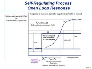
Time (seconds) %Controlled Variable (CV) or % Controller Output (CO) CO CV o p2 K p = CV CO CV CO CV Self-regulating process open loop negative feedback time constant Self-regulating process gain (%/%) Response to change in controller output with controller in manual observed total loop deadtime Self-Regulating Process Open Loop Response o or Maximum speed in 4 deadtimes is critical speed
8.
Loop Block Diagram(First Order Approximation) p1 p2 p2 K pv p1 c1 m2 m2 m1 m1 K cv c c2 Valve Process Controller Measurement K mv v v K L L L Load Upset CV CO MV PV PID Delay Lag Delay Delay Delay Delay Delay Delay Lag Lag Lag Lag Lag Lag Lag Gain Gain Gain Gain Local Set Point DV First Order Approximation : o v p1 p2 m1 m2 c v p1 m1 m2 c1 c2 (set by automation system design for analyzer, flow, pressure, level, speed, surge, and static mixer control) % % % Delay <=> Dead Time Lag <=>Time Constant K i = K mv (K pv / p2 ) K cv 100% / span K c T i T d
9.
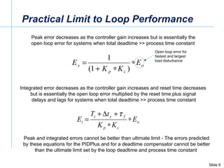
Practical Limit toLoop Performance Peak error decreases as the controller gain increases but is essentially the open loop error for systems when total deadtime >> process time constant Integrated error decreases as the controller gain increases and reset time decreases but is essentially the open loop error multiplied by the reset time plus signal delays and lags for systems when total deadtime >> process time constant Peak and integrated errors cannot be better than ultimate limit - The errors predicted by these equations for the PIDPlus and for a deadtime compensator cannot be better than the ultimate limit set by the loop deadtime and process time constant Open loop error for fastest and largest load disturbance
10.
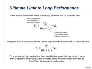
Ultimate Limit toLoop Performance Peak error is proportional to the ratio of loop deadtime to 63% response time Integrated error is proportional to the ratio of loop deadtime squared to 63% response time For a sensor lag (e.g. electrode or thermowell lag) or signal filter that is much larger than the process time constant, the unfiltered actual process variable error can be found from the equation for attenuation Total loop deadtime that is often set by automation design Largest lag in loop that is ideally set by large process volume
11.
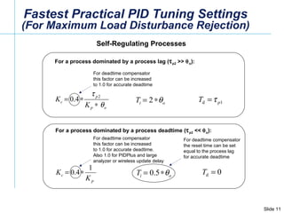
Fastest Practical PIDTuning Settings (For Maximum Load Disturbance Rejection) Self-Regulating Processes For a process dominated by a process deadtime ( p2 << o ): For deadtime compensator this factor can be increased to 1.0 for accurate deadtime For a process dominated by a process lag ( p2 >> o ): For deadtime compensator this factor can be increased to 1.0 for accurate deadtime. Also 1.0 for PIDPlus and large analyzer or wireless update delay For deadtime compensator the reset time can be set equal to the process lag for accurate deadtime
12.
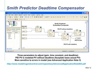
PID OUT PIDPV bias PID PV without deadtime PID PV with deadtime Smith Predictor Deadtime Compensator Three parameters to adjust (gain, time constant, and deadtime) PID PV is modeled PV without deadtime (faceplate loses actual PV) More sensitive to errors in model (see Advanced Application Note 3) http://www.modelingandcontrol.com/repository/AdvancedApplicationNote003.pdf
13.
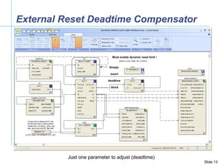
External Reset DeadtimeCompensator Simply insert deadtime block Must enable dynamic reset limit ! Just one parameter to adjust (deadtime)
14.
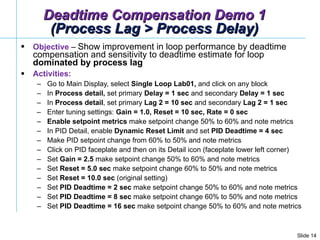
Deadtime Compensation Demo1 (Process Lag > Process Delay) Objective – Show improvement in loop performance by deadtime compensation and sensitivity to deadtime estimate for loop dominated by process lag Activities: Go to Main Display, select Single Loop Lab01, and click on any block In Process detail, set primary Delay = 1 sec and secondary Delay = 1 sec In Process detail , set primary Lag 2 = 10 sec and secondary Lag 2 = 1 sec Enter tuning settings: Gain = 1.0, Reset = 10 sec, Rate = 0 sec Enable setpoint metrics make setpoint change 50% to 60% and note metrics In PID Detail, enable Dynamic Reset Limit and set PID Deadtime = 4 sec Make PID setpoint change from 60% to 50% and note metrics Click on PID faceplate and then on its Detail icon (faceplate lower left corner) Set Gain = 2.5 make setpoint change 50% to 60% and note metrics Set Reset = 5.0 sec make setpoint change 60% to 50% and note metrics Set Reset = 10.0 sec (original setting) Set PID Deadtime = 2 sec make setpoint change 50% to 60% and note metrics Set PID Deadtime = 8 sec make setpoint change 60% to 50% and note metrics Set PID Deadtime = 16 sec make setpoint change 50% to 60% and note metrics
15.
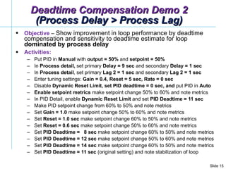
Objective – Show improvement in loop performance by deadtime compensation and sensitivity to deadtime estimate for loop dominated by process delay Activities: Put PID in Manual with output = 50% and setpoint = 50% In Process detail, set primary Delay = 9 sec and secondary Delay = 1 sec In Process detail , set primary Lag 2 = 1 sec and secondary Lag 2 = 1 sec Enter tuning settings: Gain = 0.4, Reset = 5 sec, Rate = 0 sec Disable Dynamic Reset Limit, set PID deadtime = 0 sec, and put PID in Auto Enable setpoint metrics make setpoint change 50% to 60% and note metrics In PID Detail, enable Dynamic Reset Limit and set PID Deadtime = 11 sec Make PID setpoint change from 60% to 50% and note metrics Set Gain = 1.0 make setpoint change 50% to 60% and note metrics Set Reset = 1.0 sec make setpoint change 60% to 50% and note metrics Set Reset = 0.6 sec make setpoint change 50% to 60% and note metrics Set PID Deadtime = 8 sec make setpoint change 60% to 50% and note metrics Set PID Deadtime = 12 sec make setpoint change 50% to 60% and note metrics Set PID Deadtime = 14 sec make setpoint change 60% to 50% and note metrics Set PID Deadtime = 11 sec (original setting) and note stabilization of loop Deadtime Compensation Demo 2 (Process Delay > Process Lag)
16.
Visit http://www.processcontrollab.com/ to Create Valuable New Skills Free State of the Art Virtual Plant Not an emulation but a DCS (SimulatePro) Independent Interactive Study Structural Changes “On the Fly” Advanced PID Options and Tuning Tools Enough variety of valve, measurement, and process dynamics to study 90% of the process industry’s control applications Learn in 10 minutes rather than 10 years Online Performance Metrics Standard Operator Graphics & Historian Control Room Type Environment No Modeling Expertise Needed No Configuration Expertise Needed Rapid Risk-Free Plant Experimentation Deeper Understanding of Concepts Process Control Improvement Demos Sample Lessons (Recorded Deminars) A new easy fast free method of access will be available next week that eliminates IT security issues, operator graphics resolution errors, and remote access response delays
17.
Summary of DeadtimeCompensator Test Results (Myth Busters) Deadtime is not eliminated by a deadtime compensator. The ultimate limit to loop performance of unmeasured load disturbances is still dictated by total loop deadtime (the loop cannot correct until it sees the upset and enacts a change that compensates for the upset). The response of a PID with deadtime compensation will be slower unless the PID is retuned to have a much higher gain. Improvement in performance is greater for loops where process lag > process delay (good news since few loops are deadtime dominant). A decrease in estimated deadtime causes response to degrade to a PID without deadtime compensation. An increase in estimated deadtime causes a jagged response. A loop dominated by a process lag is much less sensitive to a larger than needed deadtime than a loop dominated by a process deadtime. To minimize rise time and peak error, the PID gain is increased. For loops dominated by a process lag, only the PID gain is increased. For loops dominated by a process delay, the PID gain is increased and the reset time is decreased. The larger the process delay is compared to the process lag, the greater is the decrease in the reset time. If the reset time is not decreased, there will be severe undershoot.
18.
Help Us ImproveThese Deminars! WouldYouRecommend.Us/105679s21/
19.
Join Us Nov17, Wednesday 10:00 am CDT Feedforward Control (How to setup and adjust the dynamic compensation of feedforward signals) Look for a recording of Today’s Deminar later this week at: www.ModelingAndControl.com www.EmersonProcessXperts.com