Design of midship section based on hydrostatic and hydrodynamic loads

The ship hull is the major part of the ship which forms the skeleton of ships bottom structure. There is a need for the naval architects and engineers to make the hull a super strong structure by making the hull heavier to withstand heavy loads (which may not be needed for certain offshore conditions). If the mass of the ship increases, then the propulsive power of the hull decreases. So, the work concentrated on determination of effective thickness of the hull structure is important. Various mid ship sections of 120m container ship are modelled in Solidworks software and analysed with alloy steel, titanium alloy, and aluminium alloy in Solidworks simulation 2014 tool. Dead weight of the ship, hydrodynamic loads and hydrostatic loads were consideration during structural simulation. Best mid ship section with optimum thickness and suitable material is determined.

Recommended
Recommended
More Related Content
What's hot
What's hot (20)
Similar to Design of midship section based on hydrostatic and hydrodynamic loads
Similar to Design of midship section based on hydrostatic and hydrodynamic loads (20)
Recently uploaded
Recently uploaded (20)
Design of midship section based on hydrostatic and hydrodynamic loads
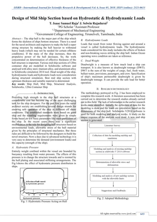
- 1. IJSRD - International Journal for Scientific Research & Development| Vol. 6, Issue 05, 2018 | ISSN (online): 2321-0613 All rights reserved by www.ijsrd.com 633 Design of Mid Ship Section based on Hydrostatic & Hydrodynamic Loads T. Isaac Samuel Raja1 J. Selwin Rajadurai2 1 PG Scholar 2 Assistant Professor 1,2 Department of Mechanical Engineering 1,2 Government College of Engineering, Tirunelveli, Tamilnadu, India Abstract— The ship hull is the major part of the ship which forms the skeleton of ships bottom structure. There is a need for the naval architects and engineers to make the hull a super strong structure by making the hull heavier to withstand heavy loads (which may not be needed for certain offshore conditions). If the mass of the ship increases, then the propulsive power of the hull decreases. So, the work concentrated on determination of effective thickness of the hull structure is important. Various mid ship sections of 120m container ship are modelled in Solidworks software and analysed with alloy steel, titanium alloy, and aluminium alloy in Solidworks simulation 2014 tool. Dead weight of the ship, hydrodynamic loads and hydrostatic loads were consideration during structural simulation. Best mid ship section with optimum thickness and suitable material is determined. Key words: Ship Hull, Mid Ship, Structural Analysis, Solidworks, 120m Container Ship I. INTRODUCTION Providing high strength in the ship hull structures at a considerable cost has become one of the most challenging task for the ship designers. For the past few years the naval architect society are establishing several design strands for ensuring safe operation of the ship in different off shore conditions. The established standards were based on good ship and the scantling requirements were given in simple forms based on few basic parameters like main particulars of the ship. In the recent years there was a significant modification in the rule for designing hull structures based on environmental loads, allowable stress of the hull material given by the principles of structural mechanics. But these rules are difficult to be followed by the designers to build the novel structure. Now a days due to advanced technology it is very easy to determine the demand (environment loads) and the capacity (strength of the ship). A. Hydrostatic Pressure Entirely weight confined within the vessel are bounded by buoyancy resulting from water pressure. The effects of this pressure is to change the structure inwards and is resisted by the hull plating and associated stiffening arrangements. The Fig.1shows the effect of hydrostatic pressure distribution in ships. Fig. 1: Hydrostatic Pressure Acting on Hull B. Hydrodynamic Loads Loads that result from water flowing against and around a vessel is called hydrodynamic loads. The hydrodynamic loads considered for this study includes the effects of broken and non-breaking waves striking the ship hull. Indian Ocean operating wave condition are taken as reference. C. Dead Weight Deadweight is a measure of how much load a ship can transport. It is also known as deadweight tonnage (DWT). DWT is the sum of the weights of cargo, fuel, fresh water, ballast water, provisions, passengers, and crew. Specification of ship's maximum permissible deadweight is given by deadweight tonnage. It can provide the safe load for better operation. II. RESEARCH METHODOLOGY The methodology portrayed in Fig. 2 has been employed to complete this research work. A literature assessment has been carried out to determine the research studies already carried out in this field. The lack of information in the earlier research works were identified. Initially the collection of data for the modeling is done and the loads are calculation based on the dimensions of the ship hull. Solidworks V2014 software is used for both modeling and analysis works. A study on the output response of the analysis were done. A new mid ship section is generated. Fig. 2: Adopted Methodology
- 2. Design of Mid Ship Section based on Hydrostatic & Hydrodynamic Loads (IJSRD/Vol. 6/Issue 05/2018/143) All rights reserved by www.ijsrd.com 634 III. LOAD CALCULATION A. Structural Loads In order to execute structural analysis, initial loading condition are necessary in this section loads which acts on the mid ship section are determined. Fig. 3: Various Components of Structural Loads The dead weight is calculated based on its structural parameters, hydrodynamic pressure is calculated by Heller and Jasper theories for pressure determination and hydrostatic pressure is calculated from the CSR rules. In the table below the data are represented. STATIC LOADS Dead weight 0.0535 Mpa Hydrostatic pressure 0.01 Mpa (bottom Shell) 0.0075 Mpa (side Shell) DYNAMIC LOADS Hydrodynamic Pressure 0.005786 Mpa Table 1: Summary of Structural Loads B. Allowable Stress & Deformation The allowable stress or allowable strength or permissible stress is the maximum stress that is allowed to be applied on a structural member. The allowable stress generally defined as in Equation (2.1) Allowable stress = Ultimate Strength F.O.S (2.1) From the reviewed journals alloy steel, titanium alloy and aluminium alloy can be used as structural materials in ship buildings. Thus we will have three different permissible stress based on Equation (2.1). C. Allowable Deformation When the original dimensions are reduced deformation may increase. So in order to make the structure to with stand the loads, effective value of allowable deflection must be given (Alice Mathai- Direct strength analysis of container ship) Allowable Deformation = 168.5 mm IV. MODELING Hull structural modeling units at the preliminary design stage that carries out the product description process such as the web frame system, stringer system, girder system, etc. defining. Using advanced system, generated an initial hull structural model, which is a 3D CAD model of the hull structure by initial modeling of the whole hull structure, in which bigger hull structural parts such as the structure systems were used. Then, a fully defined hull structural model was generated by comprehensive modeling of the hull, in which smaller hull structural parts were used. During hogging and sagging condition the mid ship section is subjected to raped failure since, all the loads acts on it. Thus effective design of mid ship section to withstand under all circumstances is very important. The following stages or steps are involved in modeling mid ship section ; Initially 2Dscaling and drafting is done for which ships mid ship section is to be modeled, manual calculation are performed for determining the dimensions of the hull plating, detailing the model with all basic dimensions. Final stage is to select the suitable material for the mid ship section. In Figure 4 plan view of the modeled mid ship section of 120m container ship is given. Fig. 4: Plan View of Mid Ship Section Fig. 5: Isometric View of Solid Structure V. SIMULATION Structural simulation integrates the fields of mechanics and dynamics as well as the many theories of failure. From a theoretical view the primary goal of structural analysis is the computation of deformations, internal forces, and stresses. To perform a precise analysis a structural engineer must determine such information as structural loads, geometry, support conditions, and materials properties. The results of such an analysis typically include support reactions, stresses and displacements. This output responses are compared to norms that indicate the conditions of failure. A. Study Property In order to perform structural analysis in Solidworks 2014 the following initiation parameters are to be assigned. Analysis type : Static Mesh type : Solid Mesh Thermal Effect: : On Zero strain temperature : 298 Kelvin
- 3. Design of Mid Ship Section based on Hydrostatic & Hydrodynamic Loads (IJSRD/Vol. 6/Issue 05/2018/143) All rights reserved by www.ijsrd.com 635 Solver type : FFE Plus Inplane Effect: : Off Soft Spring: : Off Inertial Relief: : Off Incompatible bonding options : Automatic Compute free body forces : On Friction : Off Use Adaptive Method: : Off B. Material Properties The entire structure is analysed with three different materials as described in various journals and books. The materials used are Alloy Steel Titanium Alloy (Grade- PT 3V) Aluminium alloy (Grade – 6061) Mechanical properties of the above mentioned metals are tabulated in Table 2. MECHANICAL PROPERTY Fe-C Alloy Ti Alloy Al Alloy Young’s Modulus (x 1011 N/m2 ) 2.1 1.18 6.9 Possion’s Ratio 0.28 0.33 0.33 Yield Strength (N/m2 ) 6.20 5.90 5.51 Mass density (x 108 Kg/m3 ) 7700 4450 2700 Table. 2: Mechanical Properties of Metals C. Loads & Fixtures The bottom most structure of the hull is considered to be constrained against translation in all direction and it is free to rotate about y and z direction. Structural loads acting on the hull during offshore operation are detailed in Table 1. D. Simulated Results The mid ship section is simulated for the mentioned property values. The results of the static structural analysis are the stress distribution plot, deformation plot and Strain plot. An example of each of these plot is shown in Figures 6 to 8. Note: Deformation plot shown in Figure 7 is scaled to 123.026 ratio than the original. Fig. 6: Stress Plot of Mid Ship Section Fig. 7: Deformation Plot of Mid Ship Section Fig. 8: Strain Plot of Mid Ship Section Summary of the output results are tabulated in Table. 3 MECHANICAL PROPERTY Fe-C Alloy Ti Alloy Al Alloy Stress (MPa) 148.9 142.9 142.9 Deformation (mm) 16.59 27.86 47.70 Strain (x 10-4 ) 3.495 6.082 1.037 Table 3: Simulated Results E. Review on Simulated Results From Table 3 it is obvious that the alloy steel has less displacement. Therefore the structure with steel is taken for further study. Stress induced = 148.9 Mpa Ultimate strength of alloy steel = 723.8 Mpa Displacement = 16.59 Factor of safety (F.O.S) = 2.5 Based on strength based design approach the effective dimensions of the modeled structure can be altered by taking factor of safety into account. Permissible stress = 289.52 Mpa Allowable Displacement = 168.5 mm In order to make the induced stress and deformation to the specified value, the thickness of the entire structure can be altered, structural shape can be altered, etc. In this section a redefined model is generated by reducing the thickness of the entire outer shell of the hull. When the thickness of the shell plantings are reduced from 100 mm to 67.5 mm the following results are obtained during simulation. Stress induced = 285.2 MPa Deformation produced = 26.95 mm These values are within the safe limit of the allowable stress and allowable deformation.
- 4. Design of Mid Ship Section based on Hydrostatic & Hydrodynamic Loads (IJSRD/Vol. 6/Issue 05/2018/143) All rights reserved by www.ijsrd.com 636 VI. CONCLUSION From this study it can be concluded that by reducing the shell plating thickness from an initial value based on the theories of strength based design approach, the mass of the mid ship can be reduced. Thereby contributing to higher fuel economy. REFERENCES [1] American bureau of shipping (2010), ‘ABS rules for steel vessels - vessels certificated for international voyages’. [2] Alice Mathai and George John P. (2013), ‘Direct Strength Analysis of Container Ships’, International Journal of Engineering Research and Development, Vol. 6, No. 5, pp.98-106. [3] Carl A. Thoresen (2003), ‘Port Designer's Handbook: Recommendations and Guidelines’, Thomas Telford. [4] Fuxin Huang and Chi yang (2016), ‘A review of simulation-based hydrodynamics design of ship hull forms’, Science direct journal of hydrodynamics, Vol.28. , No.6, pp.947-960. [5] Oryshchenko A. S and Kudryavtsev A. S. (2012), ‘Titanium Alloys for Shipbuilding and Nuclear Power engineering ’, Inorganic Materials: Applied Research published by Pleiades, Vol. 3, No. 6, pp. 497–506. [6] Pérez-Arribas F. and Suárez-Suárez J. A., (2006) ‘Fernández-Jambrina L. Automatic surface modeling of a ship hull’, Computer-Aided Design, Vol.38. , No.6, pp.584-594. [7] Sebastio Jose Ferraz de Oliveira Soeiro de Carvalho, ‘Structural analysis of open deck hills subjected to blending, shear and torsional loading’, Instituto Superior tecnico, Lisboa, Portugal, pp1-9. [8] Tekgoz M. , Garbatov C. and Guedes Soares C. (2018), ‘Strength assessment of an intact and damaged container ship subjected to asymmetrical bending loadings’, Marine Stuctures- Elsevier journal, Vol.58, pp.172-198.