Electro-Magnetic Acoustic Transducers
•
0 likes•379 views

From the R&D Lab to the Field

Recommended
More Related Content
What's hot
What's hot (20)
Similar to Electro-Magnetic Acoustic Transducers
Similar to Electro-Magnetic Acoustic Transducers (20)
More from Innerspec Technologies
More from Innerspec Technologies (18)
Recently uploaded
Recently uploaded (20)
Electro-Magnetic Acoustic Transducers
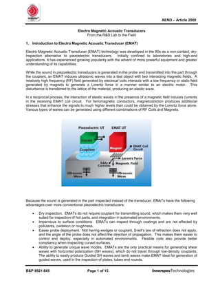
- 1. AEND – Article 2009 B&P 8921-845 Page 1 of 15 InnerspecTechnologies Electro Magnetic Acoustic Transducers From the R&D Lab to the Field 1. Introduction to Electro Magnetic Acoustic Transducer (EMAT) Electro Magnetic Acoustic Transducer (EMAT) technology was developed in the 80s as a non-contact, dry- inspection alternative to piezoelectric transducers. Initially confined to laboratories and high-end applications, it has experienced growing popularity with the advent of more powerful equipment and greater understanding of its capabilities. While the sound in piezoelectric transducers is generated in the probe and transmitted into the part through the couplant, an EMAT induces ultrasonic waves into a test object with two interacting magnetic fields. A relatively high frequency (RF) field generated by electrical coils interacts with a low frequency or static field generated by magnets to generate a Lorentz force in a manner similar to an electric motor. This disturbance is transferred to the lattice of the material, producing an elastic wave. In a reciprocal process, the interaction of elastic waves in the presence of a magnetic field induces currents in the receiving EMAT coil circuit. For ferromagnetic conductors, magnetostriction produces additional stresses that enhance the signals to much higher levels than could be obtained by the Lorentz force alone. Various types of waves can be generated using different combinations of RF Coils and Magnets. Because the sound is generated in the part inspected instead of the transducer, EMATs have the following advantages over more conventional piezoelectric transducers: • Dry inspection. EMATs do not require couplant for transmitting sound, which makes them very well suited for inspection of hot parts, and integration in automated environments. • Impervious to surface conditions. EMATs can inspect through coatings and are not affected by pollutants, oxidation or roughness. • Easier probe deployment. Not having wedges or couplant, Snell’s law of refraction does not apply, and the angle of the probe does not affect the direction of propagation. This makes them easier to control and deploy, especially in automated environments. Flexible coils also provide better compliancy when inspecting curved surfaces. • Ability to generate unique wave modes. EMATs are the only practical means for generating shear waves with horizontal polarization (SH waves), which do not travel through low-density couplants. The ability to easily produce Guided SH waves and lamb waves make EMAT ideal for generation of guided waves, used in the inspection of plates, tubes and rounds.
- 2. AEND – Article 2009 B&P 8921-845 Page 2 of 15 InnerspecTechnologies As with all nondestructive techniques, EMAT also has some restrictions that limit their suitability for certain applications: • Restricted to conductive materials. In order to transmit the energy into the part, the material needs to conduct electricity so it is mostly restricted to metals. • Transducer inefficiency. EMAT requires very high power and very precise electronic designs to generate and detect the signals. These disadvantages are becoming less relevant with new electronic and software tools that enhance complex signal processing in real time. • Large transducers. EMAT transducers are relatively large compared to piezoelectric crystals, so they are more difficult to deploy in tight spaces. • Inability to delay the signal. Because the sound is generated in the part, there is no possibility to use delay-lines or water columns. 2. Wave Modes EMAT is capable of generating all wave modes used in ultrasonic testing, including some modes that are very difficult or impractical with conventional piezoelectric transducers. The table below provides a summary guide of the type of wave and technique available for different applications. Bulk/Guided Beam Orientation Wave Mode Technique Main Applications Bulk Normal Longitudinal Piezo EMAT - Thickness and Velocity Measurements - Flaw Detection - Properties MeasurementShear Horizontal EMAT1 Angled Shear Vertical Piezo EMAT - Flaw Detection Shear Horizontal EMAT1 - Flaw Detection, including austenitic materials Guided Surface Rayleigh Piezo EMAT2 - Flaw Detection (surface) Volumetric Lamb Piezo EMAT2 - Flaw (including Corrosion) Detection - Velocity and Properties Measurements Shear Horizontal EMAT1 - Flaw (including Corrosion) Detection - Velocity and Properties Measurements 1 Generation restricted to EMAT for practical purposes 2 Especially well suited for generation with EMAT
- 3. AEND – Article 2009 B&P 8921-845 Page 3 of 15 InnerspecTechnologies 3. EMAT Capabilities We can divide ultrasonic applications in three broad categories: • Bulk, Normal Beam (zero degree incident angle) with Shear Horizontal and Longitudinal Waves. • Bulk, Angled Beam Single Channel and Phased Array • Guided Wave, Surface and Volumetric Even though it is still an ultrasonic technique, EMAT has unique features that differentiate them from other technologies. 3.1. Normal (zero degree) Beam The direction of propagation of sound is perpendicular to the entry wall (parallel to the surface). The sensor configuration can be either pulse-echo (transmitter=receiver) or pitch-catch (transmitter ≠ receiver). The technique is widely used for thickness measurement, detection of corrosion and erosion, flaw detection, acoustic velocity and properties measurement. EMAT Uniqueness • Dry and non-contact. Practical working distance from the coil to the part (lift-off) is usually between 0-3mm. Greater lift-off can be achieved (up to 10mm in laboratory settings), depending on material, equipment and type of inspection. Ideal for automated and hot environments. • Not affected by surface conditions (coatings, oil, oxide). • Maintains readings even when the probe face is not parallel to the part. The only restriction in coil/sensor angle is that derived from the loss of signal due to lift-off, so depending on the application the coil/sensor can be angled as much as 30º from the part and still obtain good signals. • Capable of generating Shear wave energy (Shear Horizontal). Shear waves have approximately half the velocity of Longitudinal waves providing better time resolution (especially important for defects next to walls). Shear waves are also is capable of detecting defects perfectly perpendicular to the direction of sound, and attenuate less than Longitudinal waves. Longitudinal waves are more difficult to generate, especially in magnetic materials. • Ability to select the direction of polarization when using Racetrack or Butterfly style coils (see RF Coil section). • Because EMAT by definition cannot use a delay line (or water column), there is a dead zone of approximately 4µs (equivalent to around 6mm of material). This dead zone can be circumvented when parallel walls are present by relying on the 2nd bounce from the wall to perform the inspection.
- 4. AEND – Article 2009 B&P 8921-845 Page 4 of 15 InnerspecTechnologies 3.2. Angled Beam The direction of propagation is at an angle from the entry wall. The sensor configuration can be either pulse-echo (transmitter=receiver) or pitch-catch (transmitter ≠ receiver). EMAT Uniqueness • Dry and non-contact. Up to 2.5mm lift-off depending on application and frequency used, although most applications require to be in very close proximity. Ideal for automated and hot environments. • Not affected by surface conditions (coatings, oil, oxide). Capable of inspecting on severely pitted surfaces. • While Angled Beam Shear Vertical energy is easy to generate using refracting angles on piezoelectric transducers (PZT), Shear Horizontal Angled Beams do not travel through low-density couplants so they are difficult to generate and excluded from applications that require scanning of the probe. • The polarity of the energy (vertical Vs horizontal) is important since shear waves do not mode convert when striking surfaces that are parallel to the direction of polarization thus Shear Horizontal waves are especially well suited for inspection of austenitic welds and other materials with dendritic grain structures. • Inspection at temperatures of up to 400ºF (200ºC). 3.3. Guided Waves The direction of propagation is parallel to the entry wall and within the boundaries of the top and bottom walls (or the cylinder when generated in a round component). Guided Waves have different motion distribution depending on the geometry and characteristics of the material that “guides” the sound. The introduction of boundary conditions make guided wave problems inherently more difficult than bulk waves. Unlike the finite number of modes present in a bulk wave problem, there are generally an infinite number of modes associated with a given guided wave problem. That is, a finite body can support an infinite number of different guided wave modes. The applications for Guided Waves are numerous and keep growing in number and acceptance. It is widely used now for weld inspection (short range guided waves), volumetric inspection of thin materials, and inspection of tubes (long range guided waves). EMAT Uniqueness • Dry and non-contact (up to 2.5mm lift-off depending on frequency and type of application). • Provides coverage of very large areas with a limited number of sensors. Ideal for automated environments. • Not affected by surface conditions (coatings, oil, oxide). • Ability to normalize the signal for automatic and continuous self-calibration. • Less sensitive to probe positioning. Especially well suited for automated weld inspection. • Ability to concentrate the energy on the outside boundaries or center of the material to be more or less sensitive to surface or internal defects (e.g. to avoid or ignore root and crown in weld inspection).
- 5. AEND – Article 2009 B&P 8921-845 Page 5 of 15 InnerspecTechnologies 4. Commercial Applications Applications of EMAT technology increase every year as the equipment becomes more powerful and affordable. The most relevant applications as of today include: 4.1. Inspection of Thin Welds Using Guided Waves. Weld inspection with piezoelectric transducers is performed using shear vertical waves generated from refraction of a longitudinal wave. The sound generated in the piezoelectric sensor travels through a layer of water which serves both to couple the transducer to the part for sound transmission, and to change the angle of the original longitudinal wave to allow the generation of the shear wave. The shear wave energy generated in this process is carefully directed to the bottom and top of the weld using the “Half Skip/Full Skip Method” shown in Figure 4. The positioning of the probe/s with regards to the weld is extremely important to provide an adequate inspection. If these angles are properly maintained, the defects, when present, reflect sound back to the sensor and are detected by the equipment. However, even a minor change in the position of the transducers or the weld will result in a failed inspection. Even when the location of the weld is well known and controlled, spurious reflections from the root and crown, and the difficulty in detecting planar defects in the center of the weld are well-known limitations of this technique. Both manufacturers of equipment and users have invested a lot of time and effort trying to ameliorate the situation. Some manufacturers have used lasers, hall sensors and other means to track the location of the weld and adjust the ultrasonic equipment on-the-fly to inspect the weld area. The latest phased-array systems use tens of channels on both sides to compensate for weld movement. These systems require very complex mechanics and electronics making them extremely costly to purchase and maintain, require constant calibration, and still suffer from the limitations inherent to the technique itself. Figure 4: ID/OD weld defect detection using “half skip/Full skip” method
- 6. AEND – Article 2009 B&P 8921-845 Page 6 of 15 InnerspecTechnologies Inspection of thin welds using guided waves (SH and Lamb) has important benefits over the conventional approach. Whereas piezoelectric transducers use a shear vertical wave, with an angle of incidence between 30º and 60º from the perpendicular to the entry wall, an EMAT-generated guided wave fills up the full volume of the material and permits inspection of the full weld in one pass. Figure 6: Advantages of Guided Waves for Thin Weld Inspection • Guided waves fill the volume of the material independent of thickness enabling inspection of the entire weld • Capable of detecting all the structural defects in the weld (lack of fusion, lack of penetration, mismatch, concavity, porosity, pinholes, cracks…) with greater reliability than angled beams and at very high speeds • Less sensitive to probe positioning, making it easier to automate and integrate into production • By selecting the appropriate wave mode and threshold level, root and crown reflections from poor flash removal can be selectively ignored, thus making it less susceptible to false rejects • In some cases, permits inspection of unscarfed welds • Separate transmitter and receiver permits normalization of the signal for self- calibration T R EMAT • Full thickness penetration • No need for rastering motion • Normalization of the signal T R EMAT T R EMAT T R EMAT • Full thickness penetration • No need for rastering motion • Normalization of the signal Figure 6: Comparison of angled beam and volumetric guided wave methods for Weld inspection
- 7. AEND – Article 2009 B&P 8921-845 Page 7 of 15 InnerspecTechnologies Existing Applications (the pictures might be too much, but here they are just in case). Innerspec Technologies has already commercialized a number of in-line and in-service inspection systems using this technology, including: • Flash-Butt welds in steel coils. Flash-butt welders are commonly used in the steel industry to weld the end of one coil to the beginning of the next one in continuous pickling operations. The temate® Si-CJ is designed to detect defects such as under and over trim, holes, overlap and other weld defects that could cause a break in the line. • Tailor Welded Blanks. Tailor Welded Blanks. Tailor Welded Blanks is a term used in the automotive industry to describe thin sheets of metal (normally from 0.5mm to 2.5mm) of different thickness or characteristics, that are welded together to improve the mechanical characteristics of the body panel The temate® Si-WB uses a proprietary sensor that detects surface and internal defects and discriminates between "planar" defects such as lack of fusion, lack of penetration, concavity or mismatch, and "point" defects such as holes and porosity.
- 8. AEND – Article 2009 B&P 8921-845 Page 8 of 15 InnerspecTechnologies • Other Butt Welds. Innerspec Technologies has developed systems to inspect longitudinal Electric Resistance Welds (with and without scarfing of the weld) in tubes, submerged arc welds in steel tanks, laser welds in propeller shafts, electron-beam in uranium disks and several other applications using this technique. • Mash Welds (RSEW-MS). The temate® Si-MW is designed for automated inspection of Mash Welds (also known as lap welds) used extensively in the manufacture of steel containers, appliances and the automobile industry.
- 9. AEND – Article 2009 B&P 8921-845 Page 9 of 15 InnerspecTechnologies • Mash Welds in Coil Joining (RSEW-MS). The temate® Si-MWC is designed for post-weld inspection of Mash Seam Welds (lap welds) in Coil Joining Operations. The system integrates seamlessly with automated welders used in galvanizing, annealing, and other finishing processes. • Laser Lap Welds. The temate® Si-LL is designed for inspection of laser lap welds which are extensively used in the automobile industry.
- 10. AEND – Article 2009 B&P 8921-845 Page 10 of 15 InnerspecTechnologies 4.2. Volumetric Inspection Using Guided Waves Guided Waves are also be used to inspect relatively thin structures (up to 12-15mm in thickness) with great sensitivity and reliability. Advantages of Guided Waves for Volumetric Inspection • Guided waves fill the volume of the material independent of thickness enabling inspection of the entire structure (plates, tubes, rods…) • Capable of detecting defects in different orientations well as corrosion and erosion, which are difficult to detect using conventional means • Permits coverage of large areas using a limited number of transducers • Works on single-material and laminated metallic composites Existing Applications (the pictures might be too much, but here they are just in case). • Ductile Iron Pipe. The temate® Ti-DP is used for inspection of iron pipes used for conduction of water and sewage in urban and suburban developments. Two sensors on top of the pipe send sound around the circumference to detect any cracks in the axial direction. The system also includes a sensor to provide a measurement of the thickness along the pipe.
- 11. AEND – Article 2009 B&P 8921-845 Page 11 of 15 InnerspecTechnologies • High Pressure Cylinders. The temate® Ti-HPC inspects high pressure cylinders using guided waves. Especially indicated to detect defects near the bottom of the tank where the differences in thickness make them very difficult to inspect with conventional angled beam systems. • Pipelines. The temate® Ti-P is used for detection of corrosion, erosion and defects in exposed pipelines in the field. Circumferential and axial modes permit complete scanning of pipes up to 36” in diameter at speeds of 4” per second (100mm/s), and detect defects in pipe supports, and other difficult to reach areas.
- 12. AEND – Article 2009 B&P 8921-845 Page 12 of 15 InnerspecTechnologies • Single and multilayered strip. The temate® Pi-GW uses lamb waves to inspect single and multilayered strip up to 15mm in thickness. The equipment uses reflection and/or attenuation and Time-Of-Flight measurement techniques to detect surface and internal defects as small as 0.1mm in thickness. The equipment is normally installed in-line as a process control tool in various manufacturing processes. • Rod. The temate® Ri uses encircling EMAT coils for internal and surface inspection of rods. By sending sound along the rod, the temate® Ri has been able to inspect rods traveling as fast as 60m/s in casting lines.
- 13. AEND – Article 2009 B&P 8921-845 Page 13 of 15 InnerspecTechnologies 4.3. Volumetric Inspection Using 0º (Normal Beam) Bulk Waves EMAT based normal beam inspection systems are used both for in-service and in-line applications because of their ability to overcome unfavorable environments and material conditions. Areas of Use for EMAT Normal Beam Systems • Very hot or very cold materials or environments • Installations or materials where water tanks or couplant delivery systems are not possible or cumbersome • Poor surface conditions of the material that impede use of conventional piezoelectric equipment • Automated inspections Existing Applications • Plate. The temate® Pi-NB is used for inspection of thick plate from 12mm to 200mm in thickness. It meets all the quality standards including EN10160, ASTM A435 and ASTM A578 • I-Beams. The temate® IB provides automated inspection of both flanges and web in forged I-beams immediately after manufacture. The equipment is designed to inspect flanges as thick as 150mm, and meet the ASTM A898 quality standard.
- 14. AEND – Article 2009 B&P 8921-845 Page 14 of 15 InnerspecTechnologies • Billets. The temate® SB is capable of detecting 2mm Flat-Bottom-Holes in square billets up to 150mm in thickness and meeting MIL-STD-2154. Actuator adapts to +/- 3º squareness between billet faces, +/- 5º of billet twist and 50mm of vertical and/or horizontal movement on 12 meters. • Thickness Testing. The temate® TG-IL is an in-line thickness measurement system capable of measuring materials below 0ºC and up to 650ºC. The system can be used on strip, plates, slabs or tubes in most factory environments.
- 15. AEND – Article 2009 B&P 8921-845 Page 15 of 15 InnerspecTechnologies • Boiler Tube. The temate® TG-IS(B) is designed for detecting wall loss, hydrogen damage and caustic gouging in boiler tubes. The proprietary technique permits inspection of heavily pitted and corroded tubes with minimum surface preparation.