1. Structures
What are structures?
In the Earth, there’s something that affects to every person, every animal, every object,
definitively, everything over its surface: Gravity. It’s a kind of force which keeps
everything on the ground. So, it has been necessary to invent airplanes and similar
flying objects to counteract its action. But it also gives to every mass the property of
weight.
Thus, every kilogram of mass receives a force of 1 kilopond (9’81 Newton) against the
ground. For this reason, it is necessary for every object and body on Earth, a kind of
structure which keeps the integrity and shape of the mass. It’s a very common example
how skeleton sustains the human body and animal bodies.
And buildings and other constructions have also to be endured in order to maintain its
integrity and shapes. This is something that civil engineers has to study about, when
they calculate and design building under parameters like critical loads, efficiency
ratings, structural testing and optimal materials selection.
Forces behavior over structures
Derived from the weight of those objects sustained or because of the structure weight
itself, some forces appear outside and inside the structure elements. Take a look to
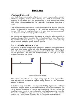
figure 1. It represents a small beam attached to a wall, in which end, a certain load (A)
has been positioned. Let’s think that the beam material is very light or at least,
incomparable with the load weight.
Figure 1 – Beam bending by a load
What happens, then, when the load weight is very large? The beam begins to bend
itself. And why does it happen? It happens, mainly, because of a bad dimensional
design of the solution.
As it’s known every material has a property called elasticity. It permits the bending of
the material, mostly if there is an outstanding dimension, like in this case happens with
a larger length in comparison, for example, with the thickness. Everyone can think that
something to make in order to improve the design could be placing a thicker beam. But
that solution would be more expensive. Engineering allows to us to develop technical
solutions with a lesser quantity of material. So, let’s going on to think a better one.
2. How cannot the beam be bent without reducing the value of the end applied force? The
solution could be the creation of a new structure which supports the load (A) with the
insertion of an additional beam (B) which composes a kind of triangle. Then, the strains
will be distributed in both beams in a stable way.
Figure 2 – Improving the design
The properties applied to this design are:
1) Composing triangles in the structure permits a better distribution
of the strains which appear by means of the applied external
forces.
2) The better strains are distributed along a structure the lesser
material it has to be used.
In this way, it’s time to take a look to some real structures that are composed in that
way, as represented in figure 3. A bridge and an electrical power tower are examples of
visible structures which are made under these conditions. They have to support a great
weight, both the structure and the supported elements.
Figure 3 – Example of structures which use a triangle composition to distribute strains
3. Searching for the center of gravity in a body
Observe the three drawings in figure 4, a triangle, a square and an arrow. Which do you
think it will fall when placing on the ground in this position?
Figure 4 – Three bodies
It’s obvious. Everybody knows that the triangle and the arrow stand on the ground in a
stable position, and even, that the square will fall down.
Every particle or molecule in each body has a certain weight and are attracted to the
ground in the same way. But if we concentrate the total weight from all of them, it will
be very simple to recognize which one of the bodies will fall down: the one which has
its weight point outside the body. In figure 5, it’s represented again the three bodies,
also drawing these significant points: the Center of gravity.
Figure 5 – Three bodies with its center of gravity positioned
So, Center of gravity can be defined as the significant point in which all the masses that
compose the bodies are concentrated. And it can be calculated having the information
from the geometry and the weight. If the body is composed by the same material
everywhere, then the weight will not be a variable in the calculation, just the geometry.
And in that case, it’s like having the average center from its geometry.
As a conclusion, symmetrical shapes offer a better stability, just because its center of
gravity is inside them. But even, those which are not symmetrical can stand on the
ground in a stable way, but having the center of gravity inside the body.
To think about
Think and write in sheet of paper your conclusions about actions applied on structures.
• Which are the reasons for an electrical tower to fall down?
• Find out in newspapers some cases of accidents about roofs fall-down in houses.
Check out the reasons that technicians found to give a technical answer to the
accident.
4. • Have you heard about destruction of a bridge? When does it happen? Why does
it happen?
5. Efficiency Rating
The efficiency rating measures the external weight or external force (F) that will cause a
structure to fail divided by the weight (W) of the structure itself. As a formula, the
efficiency rating is:
E=F/W
Figure 6 – Example of a structure which supports vehicle
In the example from figure 6, it will be the relation between the car weight and the
weight of the structure (bridge) which supports the car. The most efficient structures are
strong and lightweight - a difficult combination to achieve. For example, roofers in
areas which experience heavy snows must factor in the weight of a massive snowstorm
into designing the strength of the roof. The weight at which a building or structure fails
is called the "critical load."
Strains which appear in a structure by means of external
forces
Taking a look to Figure 6, where a vehicle is over a bridge, it’s logical to think which
kind of strains would appear in the inner elements of the structure. If that vehicle would
be very heavy, the flat part of the bridge would bend, as represented in figure 7.
Figure 7 – Reaction in a flat not very resistant bridge with a heavy weight on it
The strains which usually appear in structural mechanical elements are:
• Tension stress: The element is being forced to became longer
• Compression stress: The element is being forced to became shorter
6. • Flexure: A composition of forces which tries an element to bend or became
curved.
• Torsion strain: A composition of forces which tries to twist along a long
element. It usually happens in rounded shafts.
To simplify the designs when studying materials mechanical behavior, the supports
where mechanical parts rest could be of three kinds. The first two kinds, fixed supports
and movable supports are attached to beams and other elements by means of
articulations, so any turn is permitted. Besides, fixed support do not permit any
movement just turn, but the mentioned movable supports let the supported beam,
movements in just one direction and turns around the articulation. The third kind,
embedded supports don’t permit any movement or turn.
Figure 8 shows the supports used in mechanical elements in order to know how strains
appear in elements from typical simple structures.
Figure 8 - Supports used to set beams in a simplifying way
Inside the beam subjected to external forces and over the supports, inner strains appear
and try to deform it. Depending on the strength of forces, strains will make plastic
(permanent) deformations or elastic deformation. The elastic deformations will remain
while maintaining forces but they will disappear when forces cease.
To illustrate this definition, two examples are represented in figure 9, in which a force
F1 is on a beam maintained over two supports, fixed and movable. Then, elastic
deformations (exaggerated in the picture) appear inside the beam and make it bending.
In the right beam, two opposing forces (F2) try to elongate the beam, becoming it longer
while forces are applied.
7. Figure 9 – Examples of forces applied to beams and its mechanical consequences
8. Project to build
The proposed project related to the lesson is the construction of a structure made up of
drinking-straws.
You have to take into account some basic ideas for a successful project.
• Center properly the center of gravity of the object in order to make the structure
stable and unlikely to fall down.
• Make a structure of only straws and put them in triangles as you have seen in
the pictures above. This will make the structure more resistant to external forces
and strains will be better distributed.
Limitations to the construction
The general measures of the full construction must be up to:
- Length: 30 cm.
- Wide: 20 cm
- Height: 20 cm
- Total weight: 1 kg
The construction has to be made with a flat top surface to allocate an external load in
order to evaluate its efficiency rating. Yet, the structure can be whatever shape you
decide and you have to decide the technical application of it. The construction has to be
presented over a plywood board or over a fiberboard. To join every straw in the
structure, thermal-fusible adhesive will be applied. You may use no more than 3
adhesive sticks for the construction.
The used time to develop the documentation will be 2 class-days (it can be developed
and written at home, too). The format of the documentation has to be as usual in
Technology.
The time used to develop the object will be 6 class-days. This stage cannot be done at
home but only in the Technology workshop.
Qualifications of the project
The qualification and assessment of the project has two parts:
1) Documentation developed as a first stage. It has to be composed of a textual
description of the structure shape, structure technical application and global
measurements. This will be the 30% of the final mark
2) Built object. The higher mark will be the more quantity of straws will be used in
the structure, but really, the mark (70%) will be according to the achieved
efficiency rating when sustaining a load over it. The table will give you the
mark.
Efficiency rating Mark over 10 points
<3 3
3-5 5
5-10 7
10-20 9