SlideShare a Scribd company logo
1 of 6
Download to read offline
IOSR Journal of Electrical and Electronics Engineering (IOSR-JEEE)
e-ISSN: 2278-1676,p-ISSN: 2320-3331, Volume 12, Issue 1 Ver. II (Jan. – Feb. 2017), PP 12-17
www.iosrjournals.org
DOI: 10.9790/1676-1201021217 www.iosrjournals.org 12 | Page
Substation Earthing Design
Akshay Patil
(Electrical and Electronics Engineering, Navrachana University, India)
Abstract: Successful operation of entire power system depends to a considerable extent on efficient and
satisfactory performance of substations. Hence substations in general can be considered as heart of overall
power system. In any substation, a well-designed grounding plays an important role. Since absence of safe and
effective grounding system can result in mal-operation or non-operation of control and protective devices,
grounding system design deserves considerable attention for all the substations. There are two primary
functions of a safe earthing system. Firstly, ensure that a person who is in the vicinity of earthed facilities
during a fault is not exposed to the possibility of a fatal electrical shock. Secondly, provide a low impedance
path to earth for currents occurring under normal and fault conditions.The earthing conductors, composing the
grid and connections to all equipment and structures, must possess sufficient thermal capacity to pass the
highest fault current for the required time.
Keywords: Conductor, Earthing, Grid, Impedance, Thermal Capacity
I. Introduction
An electrical substation is a serioussource in a power system. Safe process of a substation appeals for a
well-designed and properly installed grounding system. A well-designed grounding system will safeguard
reliable performance of the substation over its entire service life.Decent grounding path of adequately low
impedance certifies fast clearing of faults. The power system stability of system may affect if fault is persisted
for a longer duration.Faster clearing thus advancestotal reliability. It also guarantees safety.A ground fault in
equipment causes the metallic enclosure potential to rise above the „true‟ ground potential. An improper
grounding results in a higher potential and also results in delayed clearing of the fault (due to insufficient current
flow). This arrangement is essentially dangerous because any person coming into contact with the enclosure is
exposed to higher potentials for a time-consuming duration.Therefore, substation dependability and protection
must be as „built-in‟ as possible by worthy grounding scheme, which will turn to safeguard faster fault clearing
and low enclosure potential rise.
Grounding system has to be safe as it is straight concerned with safety of individual‟s working within
the substation. Chief purpose of this work is designing safe and cost effective grounding systems for HV / EHV
substations situated at such locations where soil of the substation site is not uniform. Standard equations are
used in the design of earthing system to get desired parameters such as touch and step voltage criteria for safety,
earth resistance, grid resistance, maximum grid current, minimum conductor size and electrode size, maximum
fault current level and resistivity of soil. By selecting the proper horizontal conductor size, vertical electrode
size and soil resistivity, the best choice of the project for safety can be performed.Substation earthing system is
primarily not only to deliver the protection of people working in the surrounding area of earthed facilities and
equipment against danger of electric shock, but to uphold proper function of electrical system. Reliability and
security are to be taken in contemplations as well as adherence to statutory obligations.
1.1 Importance:
The earthing system in a plant / facility is very important for a few reasons, all of which are related to either the
protection of people and equipment and/or the optimal operation of the electrical system.
FIG. 1 HV Substation Earthing
Substation Earthing Design
DOI: 10.9790/1676-1201021217 www.iosrjournals.org 13 | Page
These include:
Equipotential bonding of conductive objects (e.g. metallic equipment, buildings, piping etc.) to the earthing
system prevent the presence of dangerous voltages between objects (and earth).
 The earthing system provides a low resistance return path for earth faults within the plant, which protects
both personnel and equipment.
 For earth faults with return paths to offsite generation sources, a low resistance earthing grid relative to
remote earth prevents dangerous ground potential rises (touch and step potentials)
 The earthing system provides a low resistance path (relative to remote earth) for voltage transients such as
lightning and surges / overvoltages
 Equipotential bonding helps prevent electrostatic build up and discharge, which can cause sparks with
enough energy to ignite flammable atmospheres
 The earthing system provides a reference potential for electronic circuits and helps reduce electrical noise
for electronic, instrumentation and communication systems.
 This calculation is based primarily on the guidelines provided by IEEE STD. 80 (2000), "Guide for safety
in AC substation grounding".
II. Earthing Standards
There are a variety of national and international standards available, which provide empirical formulae for the
calculation of earthing design parameters and shock potential safety limits.
 BS7354 - 1990 Code of Practice for Design of High Voltage Open Terminal Stations
 IEEE Std. 80-2000 IEEE Guide for Safety in AC Substation Grounding
 EATS 41-24 - Guidelines for the Design, Installation, Testing & Maintenance of Main Earthing Systems in
Substations.
III. Terms Associated with Earthing:
1.1 Ground Potential Rise (GPR)
The substation earth grid is used as an electrical connection to earth at zero potential reference. This
connection is not ideal due to the resistivity of the soil within which the earth grid is buried.
During typical earth fault conditions, the flow of current via the grid to earth will therefore result in the grid
rising in potential relative to remote earth to which other system neutrals are also connected.
This produces potential gradients within and around the substation ground area - this is defined as ground
potential rise or GPR.
The GPR of a substation under earth fault conditions must be limited so that step and touch potential limits are
not exceeded, and is controlled by keeping the earthing grid resistance as low as possible.
1.2 Step, Touch, Mesh & Transferred Potentials
In order to ensure the safety of people at a substation, it is necessary to ensure that step and touch potentials in
and around the substation yard during earth-fault conditions are kept below set limits.
These maximum permitted step and touch potentials are addressed within various national and international
standards.
1.3 Step Potential
The step potential is defined as the potential difference between a persons outstretched feet, normally 1 metre
apart, without the person touching any earthed structure.
1.4 Touch Potential
The touch potential is defined as the potential difference between a person‟s outstretched hand, touching an
earthed structure, and his foot. A person‟s maximum reach is normally assumed to be 1 metre.
1.5 Earthing System Design Considerations
Conductors - a substation earthing grid will consist of an earthing system of bonded cross conductors.
The earthing conductors, composing the grid and connections to all equipment and structures, must possess
sufficient thermal capacity to pass the highest fault current for the required time.
Also, the earthing conductors must have sufficient mechanical strength and corrosion resistance. It is normal
practice to bury horizontal earthing conductors at a depth of between 0.5m and 1m - this ensures that the earth
conductor has the following properties:
 Adequate mechanical protection
 It is situated below the frost line
 The surrounding earth will not dry out
1.6 Vertically Driven Earth Rods
Where there are low resistivity strata beneath the surface layer then it would be advantageous to drive
vertical earth rods down into this layer - to be effective the earth rods should be on the periphery of the site. The
length of the earth rod is chosen so as to reach the more stable layers of ground below.
Substation Earthing Design
DOI: 10.9790/1676-1201021217 www.iosrjournals.org 14 | Page
The earth rods would stabilise the earth grid resistance over seasonal resistivity changes at the grid burial depth.
1.7 Substation Fences
The earthing of metallic fences around a substation is of vital importance because dangerous touch potentials
can be involved and the fence is often accessible to the general public.
Fence earthing can be accomplished in two different ways:
Electrically connecting the fence to the earth grid, locating it within the grid area or alternatively just outside
Independently earthing the fence and locating it outside the earth grid area at a convenient place where the
potential gradient from the grid edge is acceptably low.
1.8 Other Substation Earthing
The GPR at a substation is reduced by:
Overhead line earth wires which are connected to the substation earthing grid. This diverts part of the earth fault
current to the tower footing earthing.
Cable entering and leaving the site.The armouring of such cables is usually earthed to the substation earthing
grid at both ends. Part of the earth fault current will thus be diverted to a remote earthing grid via the cable
armouring.
Nomenclature and Given Data:
NOMENCLATURE
Symbol Description
ρ Soil Resistivity
ρs Gravel Resistivity
Iefs Symmetrical Short Circuit Current
ts Duration of Earth Fault Current
hs Thickness of Crushed Gravel
h Depth of Earth Grid
ho Reference depth of the Grid
α
γ Resistivity of Conductor Material
ργ Thermal co-efficient of resistivity at reference temperature
Tm Max. allowable temperature in °C
Ta Ambient temperature in °C
Ko 1/a0 or 1/ar - Tr in °C
tc Duration of Current in s
TCAP thermal capacity per unit volume
Amm² Conductor cross section in mm²
K Reflection factor between different material resistivities
Cs Surface layer derating factor
Estep70 Step Voltage for body weight of 70 kg
Etouch70 Touch Voltage for body weight of 70 kg
Estep50 Step Voltage for body weight of 50 kg
Etouch50 Touch Voltage for body weight of 50 kg
n Number of parallel conductors
D Conductor Spacing
Lp Length of the conductor across perimeter
Nr No. of Ground Rods
Lr Length of Ground Rods
LR Total length of Ground Rods
LT1 Total length of buried conductor
LT Total length of buried conductors & rods
Lx Maximum length of conductor in X-Axis
Ly Maximum length of conductor in Y-Axis
A Area of the Grid
Rg Grid Resistance
Ig Maximum grid current in A
Df Decrement factor for the entire duration of fault, given in s
Ki Corrective factor for current irregularity
Km Spacing factor for Mesh Voltage
Kii Corrective weighting factor that adjusts the effect of inner conductors
on the corner mesh
Kh Corrective weighting factor that emphasising the grid depth
Ks Spacing factor for Step voltage
Substation Earthing Design
DOI: 10.9790/1676-1201021217 www.iosrjournals.org 15 | Page
GIVEN DATA
Sr.
no.
Description Notations Unit Value
1 Soil Resistivity ρ Ohm-M 25
2 Gravel Resistivity ρs Ohm-M 3000
3 Symmetrical Short Circuit Current Iefs A 40,000
4 Duration of Earth Fault Current ts sec 0.5
5 Thickness of Crushed Gravel hs m 0
6 Depth of Earth Grid h m 1.2
7 Reference depth of the Grid ho m 1
8 Resistivity of Conductor Material α
γ Ohm - M 0.0032
9 Thermal co-efficient of resistivity at reference temperature ργ Ohm - M 20.1
10 Max. allowable temperature in °C Tm °C 419
11 Ambient temperature in °C Ta °C 40
12 1/a0 or 1/ar - Tr in °C Ko °C 293
13 Duration of Current in s tc s 0.5
14 thermal capacity per unit volume TCAP J/cm³°C 3.93
15 Conductor cross section in mm² Amm² mm² 415.08
16 Number of parallel conductors n -- 12
17 Conductor Spacing D m 2
18 Length of the conductor across perimeter Lp m 69.5
19 No. of Ground Rods Nr -- 12
20 Length of Ground Rods Lr m 5
21 Total length of Ground Rods LR m 60
22 Total length of buried conductor LT1 m 248
23 Total length of buried conductors & rods LT m 308
24 Maximum length of conductor in X-Axis Lx m 25
25 Maximum length of conductor in Y-Axis Ly m 10
26 Area of the Grid A m² 247.5
27 Decrement factor for the entire duration of fault, given in s Df 0.415
Calculations:
Calculation Of 220 Kv Bus Section
1.9 Size Of Earthing Conductor :
Akcmil = 819.37 kcmil
Amm² = 415.08 mm²
The size of conductor selected = 23.0 mm
Diameter of the Grid Conductor d = 0.02299 m
1.10Touch & Step Criteria:
Reflection factor between different material resistivities
Surface layer derating factor
K = -0.98
Cs= 0.01
Therefore,
Estep 70 = 255.34 Volts
Etouch 70 = 230.36 Volts













 


a
m
rrc TK
TK
t
TCAP
I
Amm
0
0
4
2
ln
10

s
s
K





09.02
109.0









hs
C s
s


s
ssstep
t
CE
157.0
)61000(70

s
sstouch
t
CE
157.0
)5.11000(70

Substation Earthing Design
DOI: 10.9790/1676-1201021217 www.iosrjournals.org 16 | Page
1.11Grid Resistance:
A = Area of the Grid = 247.5 m²
Rg = Grid Resistance = 0.74 Ω
1.12Maximum Grid Current:
IG = Maximum grid current in A = 40,000
DF = Decrement factor for the entire duration of fault, given in s = 0.415
IG = 16600 A
1.13Ground Potential Rise:
GPR = 12287.2 Volts
Verification For Human Safety
The safety to personnel is specified by IEEE 80, which requires limiting the development of electrical potential
to dangerous value during earth fault current.
The regulation stipulates the following parameters to be within the permissible limit
a) Step Voltage (Foot to Foot Contact)
b) Touch Voltage(Hand to Foot Contact)
1.14Calculation For Actual Derived Step & Mesh Voltage
I. Mesh Voltage:
Ki = Corrective factor for current irregularity
Where,
na = 7.1
nb = 1.050917456
nc = 1 for square and rectangular grids
nd = 1 for square and rectangular grids and L Shaped grids
Therefore, n = 7.48
Ki = 1.75
Kii = 0.60 and
Kii = 1.00 with ground rods
Kh =
gfG IDI 














AhAL
R
T
g
/201
1
1
20
11

gG
RIGPR 
R
Lyx
r
C
imG
L
lL
L
L
KKI
DesignEmesh


















22
22.155.1
)(

nKi 148.0644.0 
dcba
nnnnn 
P
T
a
L
L
n


2
 
 















12
8
ln
48
2
16
ln
2
1
22
nKh
Kii
d
h
Dd
hD
hd
D
Km
n
ii
n
K 2
)2(
1







 
ho
h
1
Substation Earthing Design
DOI: 10.9790/1676-1201021217 www.iosrjournals.org 17 | Page
Kh = 1.48
Km = 0.57
Emesh = 1169.50 Volts (Designed)
Calculated Mesh Voltage is lower than the Tolerable Touch Voltage.
HENCE SAFE
Step Voltage:
Voltage developed for step as per the earthing system proposed during full Earth fault current.
Where,
Ks = Spacing factor for Step voltage
Ks = 0.388
Ki = 1.751772846
Estep = 1191.75 Volts (Designed)
Calculated Step Voltage is lower than the Tolerable Step Voltage.
HENCE SAFE.
IV. Conclusion
This paper has a focus on designing of a 220 kV HV/LV AC substation earthing system. The results for
earthing system are obtained by computational method. For earthing conductor and vertical earth electrode, mild
steel are used. The step by step approach for designing a substation earthing system is presented. The various
kinds of conductor sizes for earth equipment are mentioned in this paper. Construction of earthing grid is
expressed in here. The step and touch voltages are dangerous for human body. Human body may get electric
shocks from step and touch voltages. When high voltage substations are to be designed, step and touch voltages
should be calculated and values must be maintained specified standard.Importance to be given to the transfer of
Ground Potential rise (GPR) under fault conditions to avoid dangerous situations to the public, customer and
utility staff. The values of step and mesh voltages obtained for 220 kV substation are respectively 1191.75 Volt
and 1169.50 Volt which are within the permissible limits.
References
[1]. IEEE guide for safety in AC Substation Grounding,” IEEE 80-2000,pp.1-192.
[2]. IEEE std 81-1983," IEEE guide for Measuring earth Resistivity, Ground impedance, and earth surface potentials for a ground
system"
[3]. IEEE, “IEEE Recommended Practice for Determining the Electric Power Station Ground Potential Rise and Induced Voltage From
a Power Fault,” IEEE Std 367-1996, 1996, pp. 1-125
[4]. Rao Sunil S., ‗Switchgear Protection and Power Systems„. 12th edition, Khanna Publishers, New Delhi, 2007
[5]. International Journal of Advances in Engineering & Technology, Jan. 2014. IJAET ISSN: 22311963 2597 Vol. 6, Issue 6, pp. 2597-
2605 Design of earthing systemfor HV/EHV AC substation (a case study of 400kV substaion at Aurangabad, India) Swapnil. G.
Shah1 and Nitin. R. Bhasme2.
  
 RC
G
LL
IKiKs
DesignEstep



85.075.0
)(










 






DhDh
Ks
n 2
5.011
2
11
nKi 148.0644.0 

More Related Content

What's hot

Disadvantages of corona, radio interference, inductive interference between p...
Disadvantages of corona, radio interference, inductive interference between p...Disadvantages of corona, radio interference, inductive interference between p...
Disadvantages of corona, radio interference, inductive interference between p...vishalgohel12195
 
Distribution System Voltage Drop and Power Loss Calculation
Distribution System Voltage Drop and Power Loss CalculationDistribution System Voltage Drop and Power Loss Calculation
Distribution System Voltage Drop and Power Loss CalculationAmeen San
 
Unit 04 Protection of generators and transformers
Unit  04 Protection of generators and transformers Unit  04 Protection of generators and transformers
Unit 04 Protection of generators and transformers PremanandDesai
 
Earthing or Grounding
Earthing or GroundingEarthing or Grounding
Earthing or GroundingAswin KP
 
Short Circuit Calculation Symmetrical & Asymmetrical Fault Currents ?
Short Circuit Calculation Symmetrical & Asymmetrical Fault Currents ?Short Circuit Calculation Symmetrical & Asymmetrical Fault Currents ?
Short Circuit Calculation Symmetrical & Asymmetrical Fault Currents ?Power System Operation
 
FACTS DEVICES AND POWER SYSTEM STABILITY ppt
FACTS DEVICES AND POWER SYSTEM STABILITY pptFACTS DEVICES AND POWER SYSTEM STABILITY ppt
FACTS DEVICES AND POWER SYSTEM STABILITY pptMamta Bagoria
 
Earthing Concepts
Earthing ConceptsEarthing Concepts
Earthing Conceptsmvrkprasad
 
Substation protection devices
Substation protection devicesSubstation protection devices
Substation protection devicesRahul Aman
 
Overhead line work ppt
Overhead line work pptOverhead line work ppt
Overhead line work pptDemsew Mitiku
 
MTDC Systems: Control & Protection of MTDC Systems
MTDC Systems: Control & Protection of MTDC SystemsMTDC Systems: Control & Protection of MTDC Systems
MTDC Systems: Control & Protection of MTDC SystemsAsif Jamadar
 
Resistance,bundled conductor,skin effect,proximity effect
Resistance,bundled conductor,skin effect,proximity effectResistance,bundled conductor,skin effect,proximity effect
Resistance,bundled conductor,skin effect,proximity effectvishalgohel12195
 
Methods of Voltage Control
Methods of Voltage ControlMethods of Voltage Control
Methods of Voltage ControlYashvi Mehta
 
Protection of transmission lines(encrypted)
Protection of transmission lines(encrypted)Protection of transmission lines(encrypted)
Protection of transmission lines(encrypted)Rohini Haridas
 
Electrical earthing
Electrical earthingElectrical earthing
Electrical earthingPraveen Vs
 

What's hot (20)

Disadvantages of corona, radio interference, inductive interference between p...
Disadvantages of corona, radio interference, inductive interference between p...Disadvantages of corona, radio interference, inductive interference between p...
Disadvantages of corona, radio interference, inductive interference between p...
 
Distribution System Voltage Drop and Power Loss Calculation
Distribution System Voltage Drop and Power Loss CalculationDistribution System Voltage Drop and Power Loss Calculation
Distribution System Voltage Drop and Power Loss Calculation
 
Transmission Line
Transmission LineTransmission Line
Transmission Line
 
Unit 04 Protection of generators and transformers
Unit  04 Protection of generators and transformers Unit  04 Protection of generators and transformers
Unit 04 Protection of generators and transformers
 
Types of relay
Types of relayTypes of relay
Types of relay
 
Earthing or Grounding
Earthing or GroundingEarthing or Grounding
Earthing or Grounding
 
Short Circuit Calculation Symmetrical & Asymmetrical Fault Currents ?
Short Circuit Calculation Symmetrical & Asymmetrical Fault Currents ?Short Circuit Calculation Symmetrical & Asymmetrical Fault Currents ?
Short Circuit Calculation Symmetrical & Asymmetrical Fault Currents ?
 
FACTS DEVICES AND POWER SYSTEM STABILITY ppt
FACTS DEVICES AND POWER SYSTEM STABILITY pptFACTS DEVICES AND POWER SYSTEM STABILITY ppt
FACTS DEVICES AND POWER SYSTEM STABILITY ppt
 
Earthing Concepts
Earthing ConceptsEarthing Concepts
Earthing Concepts
 
Earthing system
Earthing system   Earthing system
Earthing system
 
FAULT ANALISIS IN HVDC & HVAC TRANSMISSION LINE
FAULT ANALISIS IN HVDC & HVAC TRANSMISSION LINEFAULT ANALISIS IN HVDC & HVAC TRANSMISSION LINE
FAULT ANALISIS IN HVDC & HVAC TRANSMISSION LINE
 
Substation protection devices
Substation protection devicesSubstation protection devices
Substation protection devices
 
Overhead line work ppt
Overhead line work pptOverhead line work ppt
Overhead line work ppt
 
MTDC Systems: Control & Protection of MTDC Systems
MTDC Systems: Control & Protection of MTDC SystemsMTDC Systems: Control & Protection of MTDC Systems
MTDC Systems: Control & Protection of MTDC Systems
 
Resistance,bundled conductor,skin effect,proximity effect
Resistance,bundled conductor,skin effect,proximity effectResistance,bundled conductor,skin effect,proximity effect
Resistance,bundled conductor,skin effect,proximity effect
 
Dc fed chopper
Dc fed chopperDc fed chopper
Dc fed chopper
 
Methods of Voltage Control
Methods of Voltage ControlMethods of Voltage Control
Methods of Voltage Control
 
Supports of overhead line
Supports of overhead lineSupports of overhead line
Supports of overhead line
 
Protection of transmission lines(encrypted)
Protection of transmission lines(encrypted)Protection of transmission lines(encrypted)
Protection of transmission lines(encrypted)
 
Electrical earthing
Electrical earthingElectrical earthing
Electrical earthing
 

Similar to Substation Earthing Design

Importance of Earth Mat in Substation.docx
Importance of Earth Mat in Substation.docxImportance of Earth Mat in Substation.docx
Importance of Earth Mat in Substation.docxvikram desai
 
Presentation best practice earthing and protection
Presentation   best practice earthing and protectionPresentation   best practice earthing and protection
Presentation best practice earthing and protectionMahesh Chandra Manav
 
Earthing and grounding.pptx
Earthing and grounding.pptxEarthing and grounding.pptx
Earthing and grounding.pptxSuhailAbdul2
 
Earthing Syatem
Earthing SyatemEarthing Syatem
Earthing SyatemNoman Khan
 
Designing Safe & Reliable Grounding In AC Substations With Poor Soil Resistiv...
Designing Safe & Reliable Grounding In AC Substations With Poor Soil Resistiv...Designing Safe & Reliable Grounding In AC Substations With Poor Soil Resistiv...
Designing Safe & Reliable Grounding In AC Substations With Poor Soil Resistiv...Thorne & Derrick International
 
GOOD GROUNDING PRACTICES.ppt
GOOD GROUNDING PRACTICES.pptGOOD GROUNDING PRACTICES.ppt
GOOD GROUNDING PRACTICES.pptsqhuet1
 
GOOD GROUNDING PRACTICES.ppt
GOOD GROUNDING PRACTICES.pptGOOD GROUNDING PRACTICES.ppt
GOOD GROUNDING PRACTICES.pptganesh2428364
 
Tes p-122.10-r0 (1)
Tes p-122.10-r0 (1)Tes p-122.10-r0 (1)
Tes p-122.10-r0 (1)Ibrahim Ali
 
Wael Abdel-Rahman Mohamed Ahmed_Grounding_lecture(L5).ppt
Wael Abdel-Rahman Mohamed Ahmed_Grounding_lecture(L5).pptWael Abdel-Rahman Mohamed Ahmed_Grounding_lecture(L5).ppt
Wael Abdel-Rahman Mohamed Ahmed_Grounding_lecture(L5).pptDKChaitanyarajSingh
 
Report earthing grounding pv with shielded, armoured dc cabling (worldwide)
Report earthing grounding pv with shielded, armoured dc cabling (worldwide)Report earthing grounding pv with shielded, armoured dc cabling (worldwide)
Report earthing grounding pv with shielded, armoured dc cabling (worldwide)Andreas ILIOU - Elektro- Solar
 
Impact of Buried Conductor Length on Computation of Earth Grid Resistance
Impact of Buried Conductor Length on Computation of Earth Grid ResistanceImpact of Buried Conductor Length on Computation of Earth Grid Resistance
Impact of Buried Conductor Length on Computation of Earth Grid ResistanceIJAPEJOURNAL
 
Design of Grounding System for Substation
Design of Grounding System for SubstationDesign of Grounding System for Substation
Design of Grounding System for Substationijtsrd
 
COMPENSATION OF FAULT RESISTANCE IN DISTANCE RELAY FOR LONG TRANSMISSION LINE
COMPENSATION OF FAULT RESISTANCE IN DISTANCE RELAY FOR LONG TRANSMISSION LINECOMPENSATION OF FAULT RESISTANCE IN DISTANCE RELAY FOR LONG TRANSMISSION LINE
COMPENSATION OF FAULT RESISTANCE IN DISTANCE RELAY FOR LONG TRANSMISSION LINEIRJET Journal
 
Lightning Protection Considerations for Wired Systems
Lightning Protection Considerations for Wired SystemsLightning Protection Considerations for Wired Systems
Lightning Protection Considerations for Wired SystemsAnalynk Wireless, LLC
 

Similar to Substation Earthing Design (20)

Importance of Earth Mat in Substation.docx
Importance of Earth Mat in Substation.docxImportance of Earth Mat in Substation.docx
Importance of Earth Mat in Substation.docx
 
Presentation jmv internal
Presentation jmv internalPresentation jmv internal
Presentation jmv internal
 
Presentation best practice earthing and protection
Presentation   best practice earthing and protectionPresentation   best practice earthing and protection
Presentation best practice earthing and protection
 
Earthing and grounding.pptx
Earthing and grounding.pptxEarthing and grounding.pptx
Earthing and grounding.pptx
 
Earthing Syatem
Earthing SyatemEarthing Syatem
Earthing Syatem
 
Designing Safe & Reliable Grounding In AC Substations With Poor Soil Resistiv...
Designing Safe & Reliable Grounding In AC Substations With Poor Soil Resistiv...Designing Safe & Reliable Grounding In AC Substations With Poor Soil Resistiv...
Designing Safe & Reliable Grounding In AC Substations With Poor Soil Resistiv...
 
تأريض2
تأريض2تأريض2
تأريض2
 
GOOD GROUNDING PRACTICES.ppt
GOOD GROUNDING PRACTICES.pptGOOD GROUNDING PRACTICES.ppt
GOOD GROUNDING PRACTICES.ppt
 
GOOD GROUNDING PRACTICES.ppt
GOOD GROUNDING PRACTICES.pptGOOD GROUNDING PRACTICES.ppt
GOOD GROUNDING PRACTICES.ppt
 
Tes p-122.10-r0 (1)
Tes p-122.10-r0 (1)Tes p-122.10-r0 (1)
Tes p-122.10-r0 (1)
 
Grounding.ppt
Grounding.pptGrounding.ppt
Grounding.ppt
 
Neutral grounding
Neutral groundingNeutral grounding
Neutral grounding
 
10.1.1.192.9435(1)
10.1.1.192.9435(1)10.1.1.192.9435(1)
10.1.1.192.9435(1)
 
Wael Abdel-Rahman Mohamed Ahmed_Grounding_lecture(L5).ppt
Wael Abdel-Rahman Mohamed Ahmed_Grounding_lecture(L5).pptWael Abdel-Rahman Mohamed Ahmed_Grounding_lecture(L5).ppt
Wael Abdel-Rahman Mohamed Ahmed_Grounding_lecture(L5).ppt
 
Report earthing grounding pv with shielded, armoured dc cabling (worldwide)
Report earthing grounding pv with shielded, armoured dc cabling (worldwide)Report earthing grounding pv with shielded, armoured dc cabling (worldwide)
Report earthing grounding pv with shielded, armoured dc cabling (worldwide)
 
Impact of Buried Conductor Length on Computation of Earth Grid Resistance
Impact of Buried Conductor Length on Computation of Earth Grid ResistanceImpact of Buried Conductor Length on Computation of Earth Grid Resistance
Impact of Buried Conductor Length on Computation of Earth Grid Resistance
 
Design of Grounding System for Substation
Design of Grounding System for SubstationDesign of Grounding System for Substation
Design of Grounding System for Substation
 
COMPENSATION OF FAULT RESISTANCE IN DISTANCE RELAY FOR LONG TRANSMISSION LINE
COMPENSATION OF FAULT RESISTANCE IN DISTANCE RELAY FOR LONG TRANSMISSION LINECOMPENSATION OF FAULT RESISTANCE IN DISTANCE RELAY FOR LONG TRANSMISSION LINE
COMPENSATION OF FAULT RESISTANCE IN DISTANCE RELAY FOR LONG TRANSMISSION LINE
 
Lightning Protection Considerations for Wired Systems
Lightning Protection Considerations for Wired SystemsLightning Protection Considerations for Wired Systems
Lightning Protection Considerations for Wired Systems
 
Neutral grounding
Neutral groundingNeutral grounding
Neutral grounding
 

More from IOSRJEEE

GM Distributed Generation Inverters in a Micro grid by Controlling Energy Man...
GM Distributed Generation Inverters in a Micro grid by Controlling Energy Man...GM Distributed Generation Inverters in a Micro grid by Controlling Energy Man...
GM Distributed Generation Inverters in a Micro grid by Controlling Energy Man...IOSRJEEE
 
Load Performances of a PIC Based Speed Governor for Micro Hydro Power Plant
Load Performances of a PIC Based Speed Governor for Micro Hydro Power PlantLoad Performances of a PIC Based Speed Governor for Micro Hydro Power Plant
Load Performances of a PIC Based Speed Governor for Micro Hydro Power PlantIOSRJEEE
 
A New Design in Parabolic Trough Using Heat Retention
A New Design in Parabolic Trough Using Heat RetentionA New Design in Parabolic Trough Using Heat Retention
A New Design in Parabolic Trough Using Heat RetentionIOSRJEEE
 
Investigation of Power Quality Indices in Jordanian Distribution Grid
Investigation of Power Quality Indices in Jordanian Distribution GridInvestigation of Power Quality Indices in Jordanian Distribution Grid
Investigation of Power Quality Indices in Jordanian Distribution GridIOSRJEEE
 
Improving Distribution System Performance in Deregulated Electricity Industry...
Improving Distribution System Performance in Deregulated Electricity Industry...Improving Distribution System Performance in Deregulated Electricity Industry...
Improving Distribution System Performance in Deregulated Electricity Industry...IOSRJEEE
 
High Efficiency Dc-Dc Converter for Renewable Energy Applications and High Vo...
High Efficiency Dc-Dc Converter for Renewable Energy Applications and High Vo...High Efficiency Dc-Dc Converter for Renewable Energy Applications and High Vo...
High Efficiency Dc-Dc Converter for Renewable Energy Applications and High Vo...IOSRJEEE
 
Performance Indicators For Grid-Connected PV Systems: A Case Study In Casabla...
Performance Indicators For Grid-Connected PV Systems: A Case Study In Casabla...Performance Indicators For Grid-Connected PV Systems: A Case Study In Casabla...
Performance Indicators For Grid-Connected PV Systems: A Case Study In Casabla...IOSRJEEE
 
A Review of Gas Sensors Based on Semiconducting Metal Oxide
A Review of Gas Sensors Based on Semiconducting Metal OxideA Review of Gas Sensors Based on Semiconducting Metal Oxide
A Review of Gas Sensors Based on Semiconducting Metal OxideIOSRJEEE
 
Stability Control System for a Two-Wheeler
Stability Control System for a Two-WheelerStability Control System for a Two-Wheeler
Stability Control System for a Two-WheelerIOSRJEEE
 
Voltage Sag and Swell Identification Using FFT Analysis and Mitigation with DVR
Voltage Sag and Swell Identification Using FFT Analysis and Mitigation with DVRVoltage Sag and Swell Identification Using FFT Analysis and Mitigation with DVR
Voltage Sag and Swell Identification Using FFT Analysis and Mitigation with DVRIOSRJEEE
 
Design of Intrusion Tolerance System based on Service Redundancy Level
Design of Intrusion Tolerance System based on Service Redundancy LevelDesign of Intrusion Tolerance System based on Service Redundancy Level
Design of Intrusion Tolerance System based on Service Redundancy LevelIOSRJEEE
 
Compensation of Harmonics of Fully Controlled Loads by Using SAHF
Compensation of Harmonics of Fully Controlled Loads by Using SAHFCompensation of Harmonics of Fully Controlled Loads by Using SAHF
Compensation of Harmonics of Fully Controlled Loads by Using SAHFIOSRJEEE
 
Design of Half Bridge LLC Resonant Converter for Low Voltage Dc Applications
Design of Half Bridge LLC Resonant Converter for Low Voltage Dc ApplicationsDesign of Half Bridge LLC Resonant Converter for Low Voltage Dc Applications
Design of Half Bridge LLC Resonant Converter for Low Voltage Dc ApplicationsIOSRJEEE
 
Design of the Pulse Oximetry Measurement Circuit and Its Sensing System Based...
Design of the Pulse Oximetry Measurement Circuit and Its Sensing System Based...Design of the Pulse Oximetry Measurement Circuit and Its Sensing System Based...
Design of the Pulse Oximetry Measurement Circuit and Its Sensing System Based...IOSRJEEE
 
Design of an Integrated Power Factor Converter with PI Controller for Low Pow...
Design of an Integrated Power Factor Converter with PI Controller for Low Pow...Design of an Integrated Power Factor Converter with PI Controller for Low Pow...
Design of an Integrated Power Factor Converter with PI Controller for Low Pow...IOSRJEEE
 
Magneto Optic Current Transformer Technology (MOCT)
Magneto Optic Current Transformer Technology (MOCT)Magneto Optic Current Transformer Technology (MOCT)
Magneto Optic Current Transformer Technology (MOCT)IOSRJEEE
 
On Essentiality of RoHS in EE R&D Ecosystem
On Essentiality of RoHS in EE R&D EcosystemOn Essentiality of RoHS in EE R&D Ecosystem
On Essentiality of RoHS in EE R&D EcosystemIOSRJEEE
 
A high stable on-chip CMOS temperature sensor
A high stable on-chip CMOS temperature sensorA high stable on-chip CMOS temperature sensor
A high stable on-chip CMOS temperature sensorIOSRJEEE
 
Improvement of Load Power Factor by Using Capacitor
Improvement of Load Power Factor by Using CapacitorImprovement of Load Power Factor by Using Capacitor
Improvement of Load Power Factor by Using CapacitorIOSRJEEE
 
Modeling and Simulation of Three Phase Induction Machine Using Written Pole T...
Modeling and Simulation of Three Phase Induction Machine Using Written Pole T...Modeling and Simulation of Three Phase Induction Machine Using Written Pole T...
Modeling and Simulation of Three Phase Induction Machine Using Written Pole T...IOSRJEEE
 

More from IOSRJEEE (20)

GM Distributed Generation Inverters in a Micro grid by Controlling Energy Man...
GM Distributed Generation Inverters in a Micro grid by Controlling Energy Man...GM Distributed Generation Inverters in a Micro grid by Controlling Energy Man...
GM Distributed Generation Inverters in a Micro grid by Controlling Energy Man...
 
Load Performances of a PIC Based Speed Governor for Micro Hydro Power Plant
Load Performances of a PIC Based Speed Governor for Micro Hydro Power PlantLoad Performances of a PIC Based Speed Governor for Micro Hydro Power Plant
Load Performances of a PIC Based Speed Governor for Micro Hydro Power Plant
 
A New Design in Parabolic Trough Using Heat Retention
A New Design in Parabolic Trough Using Heat RetentionA New Design in Parabolic Trough Using Heat Retention
A New Design in Parabolic Trough Using Heat Retention
 
Investigation of Power Quality Indices in Jordanian Distribution Grid
Investigation of Power Quality Indices in Jordanian Distribution GridInvestigation of Power Quality Indices in Jordanian Distribution Grid
Investigation of Power Quality Indices in Jordanian Distribution Grid
 
Improving Distribution System Performance in Deregulated Electricity Industry...
Improving Distribution System Performance in Deregulated Electricity Industry...Improving Distribution System Performance in Deregulated Electricity Industry...
Improving Distribution System Performance in Deregulated Electricity Industry...
 
High Efficiency Dc-Dc Converter for Renewable Energy Applications and High Vo...
High Efficiency Dc-Dc Converter for Renewable Energy Applications and High Vo...High Efficiency Dc-Dc Converter for Renewable Energy Applications and High Vo...
High Efficiency Dc-Dc Converter for Renewable Energy Applications and High Vo...
 
Performance Indicators For Grid-Connected PV Systems: A Case Study In Casabla...
Performance Indicators For Grid-Connected PV Systems: A Case Study In Casabla...Performance Indicators For Grid-Connected PV Systems: A Case Study In Casabla...
Performance Indicators For Grid-Connected PV Systems: A Case Study In Casabla...
 
A Review of Gas Sensors Based on Semiconducting Metal Oxide
A Review of Gas Sensors Based on Semiconducting Metal OxideA Review of Gas Sensors Based on Semiconducting Metal Oxide
A Review of Gas Sensors Based on Semiconducting Metal Oxide
 
Stability Control System for a Two-Wheeler
Stability Control System for a Two-WheelerStability Control System for a Two-Wheeler
Stability Control System for a Two-Wheeler
 
Voltage Sag and Swell Identification Using FFT Analysis and Mitigation with DVR
Voltage Sag and Swell Identification Using FFT Analysis and Mitigation with DVRVoltage Sag and Swell Identification Using FFT Analysis and Mitigation with DVR
Voltage Sag and Swell Identification Using FFT Analysis and Mitigation with DVR
 
Design of Intrusion Tolerance System based on Service Redundancy Level
Design of Intrusion Tolerance System based on Service Redundancy LevelDesign of Intrusion Tolerance System based on Service Redundancy Level
Design of Intrusion Tolerance System based on Service Redundancy Level
 
Compensation of Harmonics of Fully Controlled Loads by Using SAHF
Compensation of Harmonics of Fully Controlled Loads by Using SAHFCompensation of Harmonics of Fully Controlled Loads by Using SAHF
Compensation of Harmonics of Fully Controlled Loads by Using SAHF
 
Design of Half Bridge LLC Resonant Converter for Low Voltage Dc Applications
Design of Half Bridge LLC Resonant Converter for Low Voltage Dc ApplicationsDesign of Half Bridge LLC Resonant Converter for Low Voltage Dc Applications
Design of Half Bridge LLC Resonant Converter for Low Voltage Dc Applications
 
Design of the Pulse Oximetry Measurement Circuit and Its Sensing System Based...
Design of the Pulse Oximetry Measurement Circuit and Its Sensing System Based...Design of the Pulse Oximetry Measurement Circuit and Its Sensing System Based...
Design of the Pulse Oximetry Measurement Circuit and Its Sensing System Based...
 
Design of an Integrated Power Factor Converter with PI Controller for Low Pow...
Design of an Integrated Power Factor Converter with PI Controller for Low Pow...Design of an Integrated Power Factor Converter with PI Controller for Low Pow...
Design of an Integrated Power Factor Converter with PI Controller for Low Pow...
 
Magneto Optic Current Transformer Technology (MOCT)
Magneto Optic Current Transformer Technology (MOCT)Magneto Optic Current Transformer Technology (MOCT)
Magneto Optic Current Transformer Technology (MOCT)
 
On Essentiality of RoHS in EE R&D Ecosystem
On Essentiality of RoHS in EE R&D EcosystemOn Essentiality of RoHS in EE R&D Ecosystem
On Essentiality of RoHS in EE R&D Ecosystem
 
A high stable on-chip CMOS temperature sensor
A high stable on-chip CMOS temperature sensorA high stable on-chip CMOS temperature sensor
A high stable on-chip CMOS temperature sensor
 
Improvement of Load Power Factor by Using Capacitor
Improvement of Load Power Factor by Using CapacitorImprovement of Load Power Factor by Using Capacitor
Improvement of Load Power Factor by Using Capacitor
 
Modeling and Simulation of Three Phase Induction Machine Using Written Pole T...
Modeling and Simulation of Three Phase Induction Machine Using Written Pole T...Modeling and Simulation of Three Phase Induction Machine Using Written Pole T...
Modeling and Simulation of Three Phase Induction Machine Using Written Pole T...
 

Recently uploaded

Call Girls Narol 7397865700 Independent Call Girls
Call Girls Narol 7397865700 Independent Call GirlsCall Girls Narol 7397865700 Independent Call Girls
Call Girls Narol 7397865700 Independent Call Girlsssuser7cb4ff
 
pipeline in computer architecture design
pipeline in computer architecture  designpipeline in computer architecture  design
pipeline in computer architecture designssuser87fa0c1
 
EduAI - E learning Platform integrated with AI
EduAI - E learning Platform integrated with AIEduAI - E learning Platform integrated with AI
EduAI - E learning Platform integrated with AIkoyaldeepu123
 
Gurgaon ✡️9711147426✨Call In girls Gurgaon Sector 51 escort service
Gurgaon ✡️9711147426✨Call In girls Gurgaon Sector 51 escort serviceGurgaon ✡️9711147426✨Call In girls Gurgaon Sector 51 escort service
Gurgaon ✡️9711147426✨Call In girls Gurgaon Sector 51 escort servicejennyeacort
 
CCS355 Neural Network & Deep Learning UNIT III notes and Question bank .pdf
CCS355 Neural Network & Deep Learning UNIT III notes and Question bank .pdfCCS355 Neural Network & Deep Learning UNIT III notes and Question bank .pdf
CCS355 Neural Network & Deep Learning UNIT III notes and Question bank .pdfAsst.prof M.Gokilavani
 
Biology for Computer Engineers Course Handout.pptx
Biology for Computer Engineers Course Handout.pptxBiology for Computer Engineers Course Handout.pptx
Biology for Computer Engineers Course Handout.pptxDeepakSakkari2
 
CCS355 Neural Networks & Deep Learning Unit 1 PDF notes with Question bank .pdf
CCS355 Neural Networks & Deep Learning Unit 1 PDF notes with Question bank .pdfCCS355 Neural Networks & Deep Learning Unit 1 PDF notes with Question bank .pdf
CCS355 Neural Networks & Deep Learning Unit 1 PDF notes with Question bank .pdfAsst.prof M.Gokilavani
 
Call Us ≽ 8377877756 ≼ Call Girls In Shastri Nagar (Delhi)
Call Us ≽ 8377877756 ≼ Call Girls In Shastri Nagar (Delhi)Call Us ≽ 8377877756 ≼ Call Girls In Shastri Nagar (Delhi)
Call Us ≽ 8377877756 ≼ Call Girls In Shastri Nagar (Delhi)dollysharma2066
 
Past, Present and Future of Generative AI
Past, Present and Future of Generative AIPast, Present and Future of Generative AI
Past, Present and Future of Generative AIabhishek36461
 
Decoding Kotlin - Your guide to solving the mysterious in Kotlin.pptx
Decoding Kotlin - Your guide to solving the mysterious in Kotlin.pptxDecoding Kotlin - Your guide to solving the mysterious in Kotlin.pptx
Decoding Kotlin - Your guide to solving the mysterious in Kotlin.pptxJoão Esperancinha
 
Sachpazis Costas: Geotechnical Engineering: A student's Perspective Introduction
Sachpazis Costas: Geotechnical Engineering: A student's Perspective IntroductionSachpazis Costas: Geotechnical Engineering: A student's Perspective Introduction
Sachpazis Costas: Geotechnical Engineering: A student's Perspective IntroductionDr.Costas Sachpazis
 
Risk Assessment For Installation of Drainage Pipes.pdf
Risk Assessment For Installation of Drainage Pipes.pdfRisk Assessment For Installation of Drainage Pipes.pdf
Risk Assessment For Installation of Drainage Pipes.pdfROCENODodongVILLACER
 
UNIT III ANALOG ELECTRONICS (BASIC ELECTRONICS)
UNIT III ANALOG ELECTRONICS (BASIC ELECTRONICS)UNIT III ANALOG ELECTRONICS (BASIC ELECTRONICS)
UNIT III ANALOG ELECTRONICS (BASIC ELECTRONICS)Dr SOUNDIRARAJ N
 
Introduction to Machine Learning Unit-3 for II MECH
Introduction to Machine Learning Unit-3 for II MECHIntroduction to Machine Learning Unit-3 for II MECH
Introduction to Machine Learning Unit-3 for II MECHC Sai Kiran
 
Call Girls Delhi {Jodhpur} 9711199012 high profile service
Call Girls Delhi {Jodhpur} 9711199012 high profile serviceCall Girls Delhi {Jodhpur} 9711199012 high profile service
Call Girls Delhi {Jodhpur} 9711199012 high profile servicerehmti665
 
Study on Air-Water & Water-Water Heat Exchange in a Finned Tube Exchanger
Study on Air-Water & Water-Water Heat Exchange in a Finned Tube ExchangerStudy on Air-Water & Water-Water Heat Exchange in a Finned Tube Exchanger
Study on Air-Water & Water-Water Heat Exchange in a Finned Tube ExchangerAnamika Sarkar
 
Work Experience-Dalton Park.pptxfvvvvvvv
Work Experience-Dalton Park.pptxfvvvvvvvWork Experience-Dalton Park.pptxfvvvvvvv
Work Experience-Dalton Park.pptxfvvvvvvvLewisJB
 

Recently uploaded (20)

Call Girls Narol 7397865700 Independent Call Girls
Call Girls Narol 7397865700 Independent Call GirlsCall Girls Narol 7397865700 Independent Call Girls
Call Girls Narol 7397865700 Independent Call Girls
 
pipeline in computer architecture design
pipeline in computer architecture  designpipeline in computer architecture  design
pipeline in computer architecture design
 
Call Us -/9953056974- Call Girls In Vikaspuri-/- Delhi NCR
Call Us -/9953056974- Call Girls In Vikaspuri-/- Delhi NCRCall Us -/9953056974- Call Girls In Vikaspuri-/- Delhi NCR
Call Us -/9953056974- Call Girls In Vikaspuri-/- Delhi NCR
 
EduAI - E learning Platform integrated with AI
EduAI - E learning Platform integrated with AIEduAI - E learning Platform integrated with AI
EduAI - E learning Platform integrated with AI
 
Gurgaon ✡️9711147426✨Call In girls Gurgaon Sector 51 escort service
Gurgaon ✡️9711147426✨Call In girls Gurgaon Sector 51 escort serviceGurgaon ✡️9711147426✨Call In girls Gurgaon Sector 51 escort service
Gurgaon ✡️9711147426✨Call In girls Gurgaon Sector 51 escort service
 
CCS355 Neural Network & Deep Learning UNIT III notes and Question bank .pdf
CCS355 Neural Network & Deep Learning UNIT III notes and Question bank .pdfCCS355 Neural Network & Deep Learning UNIT III notes and Question bank .pdf
CCS355 Neural Network & Deep Learning UNIT III notes and Question bank .pdf
 
Biology for Computer Engineers Course Handout.pptx
Biology for Computer Engineers Course Handout.pptxBiology for Computer Engineers Course Handout.pptx
Biology for Computer Engineers Course Handout.pptx
 
CCS355 Neural Networks & Deep Learning Unit 1 PDF notes with Question bank .pdf
CCS355 Neural Networks & Deep Learning Unit 1 PDF notes with Question bank .pdfCCS355 Neural Networks & Deep Learning Unit 1 PDF notes with Question bank .pdf
CCS355 Neural Networks & Deep Learning Unit 1 PDF notes with Question bank .pdf
 
Call Us ≽ 8377877756 ≼ Call Girls In Shastri Nagar (Delhi)
Call Us ≽ 8377877756 ≼ Call Girls In Shastri Nagar (Delhi)Call Us ≽ 8377877756 ≼ Call Girls In Shastri Nagar (Delhi)
Call Us ≽ 8377877756 ≼ Call Girls In Shastri Nagar (Delhi)
 
Past, Present and Future of Generative AI
Past, Present and Future of Generative AIPast, Present and Future of Generative AI
Past, Present and Future of Generative AI
 
Decoding Kotlin - Your guide to solving the mysterious in Kotlin.pptx
Decoding Kotlin - Your guide to solving the mysterious in Kotlin.pptxDecoding Kotlin - Your guide to solving the mysterious in Kotlin.pptx
Decoding Kotlin - Your guide to solving the mysterious in Kotlin.pptx
 
Sachpazis Costas: Geotechnical Engineering: A student's Perspective Introduction
Sachpazis Costas: Geotechnical Engineering: A student's Perspective IntroductionSachpazis Costas: Geotechnical Engineering: A student's Perspective Introduction
Sachpazis Costas: Geotechnical Engineering: A student's Perspective Introduction
 
🔝9953056974🔝!!-YOUNG call girls in Rajendra Nagar Escort rvice Shot 2000 nigh...
🔝9953056974🔝!!-YOUNG call girls in Rajendra Nagar Escort rvice Shot 2000 nigh...🔝9953056974🔝!!-YOUNG call girls in Rajendra Nagar Escort rvice Shot 2000 nigh...
🔝9953056974🔝!!-YOUNG call girls in Rajendra Nagar Escort rvice Shot 2000 nigh...
 
Risk Assessment For Installation of Drainage Pipes.pdf
Risk Assessment For Installation of Drainage Pipes.pdfRisk Assessment For Installation of Drainage Pipes.pdf
Risk Assessment For Installation of Drainage Pipes.pdf
 
UNIT III ANALOG ELECTRONICS (BASIC ELECTRONICS)
UNIT III ANALOG ELECTRONICS (BASIC ELECTRONICS)UNIT III ANALOG ELECTRONICS (BASIC ELECTRONICS)
UNIT III ANALOG ELECTRONICS (BASIC ELECTRONICS)
 
Exploring_Network_Security_with_JA3_by_Rakesh Seal.pptx
Exploring_Network_Security_with_JA3_by_Rakesh Seal.pptxExploring_Network_Security_with_JA3_by_Rakesh Seal.pptx
Exploring_Network_Security_with_JA3_by_Rakesh Seal.pptx
 
Introduction to Machine Learning Unit-3 for II MECH
Introduction to Machine Learning Unit-3 for II MECHIntroduction to Machine Learning Unit-3 for II MECH
Introduction to Machine Learning Unit-3 for II MECH
 
Call Girls Delhi {Jodhpur} 9711199012 high profile service
Call Girls Delhi {Jodhpur} 9711199012 high profile serviceCall Girls Delhi {Jodhpur} 9711199012 high profile service
Call Girls Delhi {Jodhpur} 9711199012 high profile service
 
Study on Air-Water & Water-Water Heat Exchange in a Finned Tube Exchanger
Study on Air-Water & Water-Water Heat Exchange in a Finned Tube ExchangerStudy on Air-Water & Water-Water Heat Exchange in a Finned Tube Exchanger
Study on Air-Water & Water-Water Heat Exchange in a Finned Tube Exchanger
 
Work Experience-Dalton Park.pptxfvvvvvvv
Work Experience-Dalton Park.pptxfvvvvvvvWork Experience-Dalton Park.pptxfvvvvvvv
Work Experience-Dalton Park.pptxfvvvvvvv
 

Substation Earthing Design

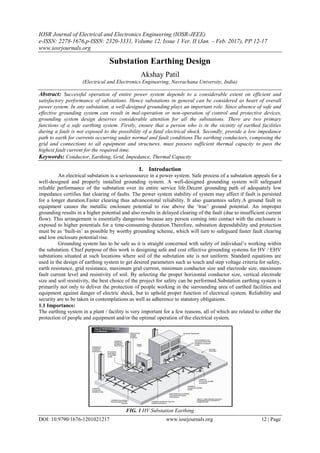
  • 1. IOSR Journal of Electrical and Electronics Engineering (IOSR-JEEE) e-ISSN: 2278-1676,p-ISSN: 2320-3331, Volume 12, Issue 1 Ver. II (Jan. – Feb. 2017), PP 12-17 www.iosrjournals.org DOI: 10.9790/1676-1201021217 www.iosrjournals.org 12 | Page Substation Earthing Design Akshay Patil (Electrical and Electronics Engineering, Navrachana University, India) Abstract: Successful operation of entire power system depends to a considerable extent on efficient and satisfactory performance of substations. Hence substations in general can be considered as heart of overall power system. In any substation, a well-designed grounding plays an important role. Since absence of safe and effective grounding system can result in mal-operation or non-operation of control and protective devices, grounding system design deserves considerable attention for all the substations. There are two primary functions of a safe earthing system. Firstly, ensure that a person who is in the vicinity of earthed facilities during a fault is not exposed to the possibility of a fatal electrical shock. Secondly, provide a low impedance path to earth for currents occurring under normal and fault conditions.The earthing conductors, composing the grid and connections to all equipment and structures, must possess sufficient thermal capacity to pass the highest fault current for the required time. Keywords: Conductor, Earthing, Grid, Impedance, Thermal Capacity I. Introduction An electrical substation is a serioussource in a power system. Safe process of a substation appeals for a well-designed and properly installed grounding system. A well-designed grounding system will safeguard reliable performance of the substation over its entire service life.Decent grounding path of adequately low impedance certifies fast clearing of faults. The power system stability of system may affect if fault is persisted for a longer duration.Faster clearing thus advancestotal reliability. It also guarantees safety.A ground fault in equipment causes the metallic enclosure potential to rise above the „true‟ ground potential. An improper grounding results in a higher potential and also results in delayed clearing of the fault (due to insufficient current flow). This arrangement is essentially dangerous because any person coming into contact with the enclosure is exposed to higher potentials for a time-consuming duration.Therefore, substation dependability and protection must be as „built-in‟ as possible by worthy grounding scheme, which will turn to safeguard faster fault clearing and low enclosure potential rise. Grounding system has to be safe as it is straight concerned with safety of individual‟s working within the substation. Chief purpose of this work is designing safe and cost effective grounding systems for HV / EHV substations situated at such locations where soil of the substation site is not uniform. Standard equations are used in the design of earthing system to get desired parameters such as touch and step voltage criteria for safety, earth resistance, grid resistance, maximum grid current, minimum conductor size and electrode size, maximum fault current level and resistivity of soil. By selecting the proper horizontal conductor size, vertical electrode size and soil resistivity, the best choice of the project for safety can be performed.Substation earthing system is primarily not only to deliver the protection of people working in the surrounding area of earthed facilities and equipment against danger of electric shock, but to uphold proper function of electrical system. Reliability and security are to be taken in contemplations as well as adherence to statutory obligations. 1.1 Importance: The earthing system in a plant / facility is very important for a few reasons, all of which are related to either the protection of people and equipment and/or the optimal operation of the electrical system. FIG. 1 HV Substation Earthing
  • 2. Substation Earthing Design DOI: 10.9790/1676-1201021217 www.iosrjournals.org 13 | Page These include: Equipotential bonding of conductive objects (e.g. metallic equipment, buildings, piping etc.) to the earthing system prevent the presence of dangerous voltages between objects (and earth).  The earthing system provides a low resistance return path for earth faults within the plant, which protects both personnel and equipment.  For earth faults with return paths to offsite generation sources, a low resistance earthing grid relative to remote earth prevents dangerous ground potential rises (touch and step potentials)  The earthing system provides a low resistance path (relative to remote earth) for voltage transients such as lightning and surges / overvoltages  Equipotential bonding helps prevent electrostatic build up and discharge, which can cause sparks with enough energy to ignite flammable atmospheres  The earthing system provides a reference potential for electronic circuits and helps reduce electrical noise for electronic, instrumentation and communication systems.  This calculation is based primarily on the guidelines provided by IEEE STD. 80 (2000), "Guide for safety in AC substation grounding". II. Earthing Standards There are a variety of national and international standards available, which provide empirical formulae for the calculation of earthing design parameters and shock potential safety limits.  BS7354 - 1990 Code of Practice for Design of High Voltage Open Terminal Stations  IEEE Std. 80-2000 IEEE Guide for Safety in AC Substation Grounding  EATS 41-24 - Guidelines for the Design, Installation, Testing & Maintenance of Main Earthing Systems in Substations. III. Terms Associated with Earthing: 1.1 Ground Potential Rise (GPR) The substation earth grid is used as an electrical connection to earth at zero potential reference. This connection is not ideal due to the resistivity of the soil within which the earth grid is buried. During typical earth fault conditions, the flow of current via the grid to earth will therefore result in the grid rising in potential relative to remote earth to which other system neutrals are also connected. This produces potential gradients within and around the substation ground area - this is defined as ground potential rise or GPR. The GPR of a substation under earth fault conditions must be limited so that step and touch potential limits are not exceeded, and is controlled by keeping the earthing grid resistance as low as possible. 1.2 Step, Touch, Mesh & Transferred Potentials In order to ensure the safety of people at a substation, it is necessary to ensure that step and touch potentials in and around the substation yard during earth-fault conditions are kept below set limits. These maximum permitted step and touch potentials are addressed within various national and international standards. 1.3 Step Potential The step potential is defined as the potential difference between a persons outstretched feet, normally 1 metre apart, without the person touching any earthed structure. 1.4 Touch Potential The touch potential is defined as the potential difference between a person‟s outstretched hand, touching an earthed structure, and his foot. A person‟s maximum reach is normally assumed to be 1 metre. 1.5 Earthing System Design Considerations Conductors - a substation earthing grid will consist of an earthing system of bonded cross conductors. The earthing conductors, composing the grid and connections to all equipment and structures, must possess sufficient thermal capacity to pass the highest fault current for the required time. Also, the earthing conductors must have sufficient mechanical strength and corrosion resistance. It is normal practice to bury horizontal earthing conductors at a depth of between 0.5m and 1m - this ensures that the earth conductor has the following properties:  Adequate mechanical protection  It is situated below the frost line  The surrounding earth will not dry out 1.6 Vertically Driven Earth Rods Where there are low resistivity strata beneath the surface layer then it would be advantageous to drive vertical earth rods down into this layer - to be effective the earth rods should be on the periphery of the site. The length of the earth rod is chosen so as to reach the more stable layers of ground below.
  • 3. Substation Earthing Design DOI: 10.9790/1676-1201021217 www.iosrjournals.org 14 | Page The earth rods would stabilise the earth grid resistance over seasonal resistivity changes at the grid burial depth. 1.7 Substation Fences The earthing of metallic fences around a substation is of vital importance because dangerous touch potentials can be involved and the fence is often accessible to the general public. Fence earthing can be accomplished in two different ways: Electrically connecting the fence to the earth grid, locating it within the grid area or alternatively just outside Independently earthing the fence and locating it outside the earth grid area at a convenient place where the potential gradient from the grid edge is acceptably low. 1.8 Other Substation Earthing The GPR at a substation is reduced by: Overhead line earth wires which are connected to the substation earthing grid. This diverts part of the earth fault current to the tower footing earthing. Cable entering and leaving the site.The armouring of such cables is usually earthed to the substation earthing grid at both ends. Part of the earth fault current will thus be diverted to a remote earthing grid via the cable armouring. Nomenclature and Given Data: NOMENCLATURE Symbol Description ρ Soil Resistivity ρs Gravel Resistivity Iefs Symmetrical Short Circuit Current ts Duration of Earth Fault Current hs Thickness of Crushed Gravel h Depth of Earth Grid ho Reference depth of the Grid α γ Resistivity of Conductor Material ργ Thermal co-efficient of resistivity at reference temperature Tm Max. allowable temperature in °C Ta Ambient temperature in °C Ko 1/a0 or 1/ar - Tr in °C tc Duration of Current in s TCAP thermal capacity per unit volume Amm² Conductor cross section in mm² K Reflection factor between different material resistivities Cs Surface layer derating factor Estep70 Step Voltage for body weight of 70 kg Etouch70 Touch Voltage for body weight of 70 kg Estep50 Step Voltage for body weight of 50 kg Etouch50 Touch Voltage for body weight of 50 kg n Number of parallel conductors D Conductor Spacing Lp Length of the conductor across perimeter Nr No. of Ground Rods Lr Length of Ground Rods LR Total length of Ground Rods LT1 Total length of buried conductor LT Total length of buried conductors & rods Lx Maximum length of conductor in X-Axis Ly Maximum length of conductor in Y-Axis A Area of the Grid Rg Grid Resistance Ig Maximum grid current in A Df Decrement factor for the entire duration of fault, given in s Ki Corrective factor for current irregularity Km Spacing factor for Mesh Voltage Kii Corrective weighting factor that adjusts the effect of inner conductors on the corner mesh Kh Corrective weighting factor that emphasising the grid depth Ks Spacing factor for Step voltage
  • 4. Substation Earthing Design DOI: 10.9790/1676-1201021217 www.iosrjournals.org 15 | Page GIVEN DATA Sr. no. Description Notations Unit Value 1 Soil Resistivity ρ Ohm-M 25 2 Gravel Resistivity ρs Ohm-M 3000 3 Symmetrical Short Circuit Current Iefs A 40,000 4 Duration of Earth Fault Current ts sec 0.5 5 Thickness of Crushed Gravel hs m 0 6 Depth of Earth Grid h m 1.2 7 Reference depth of the Grid ho m 1 8 Resistivity of Conductor Material α γ Ohm - M 0.0032 9 Thermal co-efficient of resistivity at reference temperature ργ Ohm - M 20.1 10 Max. allowable temperature in °C Tm °C 419 11 Ambient temperature in °C Ta °C 40 12 1/a0 or 1/ar - Tr in °C Ko °C 293 13 Duration of Current in s tc s 0.5 14 thermal capacity per unit volume TCAP J/cm³°C 3.93 15 Conductor cross section in mm² Amm² mm² 415.08 16 Number of parallel conductors n -- 12 17 Conductor Spacing D m 2 18 Length of the conductor across perimeter Lp m 69.5 19 No. of Ground Rods Nr -- 12 20 Length of Ground Rods Lr m 5 21 Total length of Ground Rods LR m 60 22 Total length of buried conductor LT1 m 248 23 Total length of buried conductors & rods LT m 308 24 Maximum length of conductor in X-Axis Lx m 25 25 Maximum length of conductor in Y-Axis Ly m 10 26 Area of the Grid A m² 247.5 27 Decrement factor for the entire duration of fault, given in s Df 0.415 Calculations: Calculation Of 220 Kv Bus Section 1.9 Size Of Earthing Conductor : Akcmil = 819.37 kcmil Amm² = 415.08 mm² The size of conductor selected = 23.0 mm Diameter of the Grid Conductor d = 0.02299 m 1.10Touch & Step Criteria: Reflection factor between different material resistivities Surface layer derating factor K = -0.98 Cs= 0.01 Therefore, Estep 70 = 255.34 Volts Etouch 70 = 230.36 Volts                  a m rrc TK TK t TCAP I Amm 0 0 4 2 ln 10  s s K      09.02 109.0          hs C s s   s ssstep t CE 157.0 )61000(70  s sstouch t CE 157.0 )5.11000(70 
  • 5. Substation Earthing Design DOI: 10.9790/1676-1201021217 www.iosrjournals.org 16 | Page 1.11Grid Resistance: A = Area of the Grid = 247.5 m² Rg = Grid Resistance = 0.74 Ω 1.12Maximum Grid Current: IG = Maximum grid current in A = 40,000 DF = Decrement factor for the entire duration of fault, given in s = 0.415 IG = 16600 A 1.13Ground Potential Rise: GPR = 12287.2 Volts Verification For Human Safety The safety to personnel is specified by IEEE 80, which requires limiting the development of electrical potential to dangerous value during earth fault current. The regulation stipulates the following parameters to be within the permissible limit a) Step Voltage (Foot to Foot Contact) b) Touch Voltage(Hand to Foot Contact) 1.14Calculation For Actual Derived Step & Mesh Voltage I. Mesh Voltage: Ki = Corrective factor for current irregularity Where, na = 7.1 nb = 1.050917456 nc = 1 for square and rectangular grids nd = 1 for square and rectangular grids and L Shaped grids Therefore, n = 7.48 Ki = 1.75 Kii = 0.60 and Kii = 1.00 with ground rods Kh = gfG IDI                AhAL R T g /201 1 1 20 11  gG RIGPR  R Lyx r C imG L lL L L KKI DesignEmesh                   22 22.155.1 )(  nKi 148.0644.0  dcba nnnnn  P T a L L n   2                    12 8 ln 48 2 16 ln 2 1 22 nKh Kii d h Dd hD hd D Km n ii n K 2 )2( 1          ho h 1
  • 6. Substation Earthing Design DOI: 10.9790/1676-1201021217 www.iosrjournals.org 17 | Page Kh = 1.48 Km = 0.57 Emesh = 1169.50 Volts (Designed) Calculated Mesh Voltage is lower than the Tolerable Touch Voltage. HENCE SAFE Step Voltage: Voltage developed for step as per the earthing system proposed during full Earth fault current. Where, Ks = Spacing factor for Step voltage Ks = 0.388 Ki = 1.751772846 Estep = 1191.75 Volts (Designed) Calculated Step Voltage is lower than the Tolerable Step Voltage. HENCE SAFE. IV. Conclusion This paper has a focus on designing of a 220 kV HV/LV AC substation earthing system. The results for earthing system are obtained by computational method. For earthing conductor and vertical earth electrode, mild steel are used. The step by step approach for designing a substation earthing system is presented. The various kinds of conductor sizes for earth equipment are mentioned in this paper. Construction of earthing grid is expressed in here. The step and touch voltages are dangerous for human body. Human body may get electric shocks from step and touch voltages. When high voltage substations are to be designed, step and touch voltages should be calculated and values must be maintained specified standard.Importance to be given to the transfer of Ground Potential rise (GPR) under fault conditions to avoid dangerous situations to the public, customer and utility staff. The values of step and mesh voltages obtained for 220 kV substation are respectively 1191.75 Volt and 1169.50 Volt which are within the permissible limits. References [1]. IEEE guide for safety in AC Substation Grounding,” IEEE 80-2000,pp.1-192. [2]. IEEE std 81-1983," IEEE guide for Measuring earth Resistivity, Ground impedance, and earth surface potentials for a ground system" [3]. IEEE, “IEEE Recommended Practice for Determining the Electric Power Station Ground Potential Rise and Induced Voltage From a Power Fault,” IEEE Std 367-1996, 1996, pp. 1-125 [4]. Rao Sunil S., ‗Switchgear Protection and Power Systems„. 12th edition, Khanna Publishers, New Delhi, 2007 [5]. International Journal of Advances in Engineering & Technology, Jan. 2014. IJAET ISSN: 22311963 2597 Vol. 6, Issue 6, pp. 2597- 2605 Design of earthing systemfor HV/EHV AC substation (a case study of 400kV substaion at Aurangabad, India) Swapnil. G. Shah1 and Nitin. R. Bhasme2.     RC G LL IKiKs DesignEstep    85.075.0 )(                   DhDh Ks n 2 5.011 2 11 nKi 148.0644.0 