
Recommended
Recommended
More Related Content
What's hot
What's hot (20)
Similar to GA Based Controller Optimizes Wind-Diesel Microgrid
Similar to GA Based Controller Optimizes Wind-Diesel Microgrid (20)
More from IOSRJEEE
More from IOSRJEEE (20)
Recently uploaded
Recently uploaded (20)
GA Based Controller Optimizes Wind-Diesel Microgrid
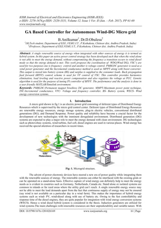
- 1. IOSR Journal of Electrical and Electronics Engineering (IOSR-JEEE) e-ISSN: 2278-1676,p-ISSN: 2320-3331, Volume 12, Issue 1 Ver. II (Jan. – Feb. 2017), PP 61-69 www.iosrjournals.org DOI: 10.9790/1676-1201026169 www.iosrjournals.org 61 | Page GA Based Controller for Autonomous Wind-DG Micro grid B.Anilkumar1 , Dr.D.Obulesu2 1 (M.Tech student, Department of EEE.,VEMU.I.T., P.Kothakota, Chittoor dist, Andhra Pradesh, India) 2 (Professor, Department of EEE,VEMU.I.T., P.Kothakota, Chittoor dist, Andhra Pradesh, India) Abstract: A single renewable source of energy when integrated with other sources of energy it is termed as hybrid system. In this paper an active power control strategy has been developed such that when the wind alone is not able to meet the energy demand, without compromising the frequency a transition occurs to wind diesel mode so that the energy demand is met. This work proposes the coordination of WDG(Wind DG), VSC’s are used for two purposes one is frequency control and another is voltage control. PMBLDC generator is used as a wind power generator and the Incremental conductance method is used as MPPT along with boost converter. This output is stored into battery system (BS) and surplus is supplied to the consumer loads. Back propagation feed forward (BPFF) control scheme is used for VF control of VSC. This controller provides harmonics elimination, load leveling and reactive power compensation and also regulates the voltage at PCC. Genetic algorithm is used for the purpose of tuning PI controller of BPFF. The performance and the analysis is done in a user friendly MATLAB/Simulink environment. Keywords: PMBLDC-Permanent magnet brushless DC generator, MMPT-Maximum power point technique, INC-Incremental conductance, VFC- Voltage and frequency controller, BS- Battery system, WECS- Wind energy conversion systems. I. Introduction A micro grid shown in fig.1 is an electric power grid consisting of deferent types of Distributed Energy Resources which is supervised by the micro grid control center. Deferent types of Distributed Energy Resources are renewable energy resources, energy storage systems, plug-in electric vehicles, conventional distributed generations (DG), and Demand Response. Power quality and reliability have become a crucial factor for the development of new technologies with the imminent deregulated environment. Distributed generation (DG) systems are expected to play a major role to meet the energy demand with clean environment. DG technologies such as photovoltaic systems, wind turbine, fuel cell, diesel engines are used in various places. Wind energy has received the special attention of researchers in recent times. Fig: 1. Microgrid structure. The advent of power electronic devices have steered a new era of power quality while integrating them with the renewable sources of energy. The renewable systems can either be interfaced with the existing grids or can be operated on a stand-alone basis. Effective capture of wind energy can definitely help to meet the energy needs as is evident in countries such as Germany, Netherlands, Canada etc. Stand alone or isolated systems are common in islands or far rural areas where the utility grid can‟t reach. A single renewable energy source may not be able to meet the load demands apart from the fact that continuous supply of energy may not be ensured (say wind is not available on a particular day in a wind farm). This makes the importance of hybrid energy systems such as wind- PV, wind-diesel along with use of battery etc. Owing to the fast controllability and response time of the diesel engines, they are quite popular for integration with wind energy conversion systems (WECS). Hence a wind diesel hybrid system is considered in the thesis. Induction generators are utilized for wind systems.The main challenges with renewable resources are their unpredictability and variable nature. With
- 2. GA Based Controller for Autonomous Wind-DG Micro grid DOI: 10.9790/1676-1201026169 www.iosrjournals.org 62 | Page these resources, minimizing power supply variations and maintaining power quality are the prime issues for researchers. In difficult geographical terrains where main power grid is not accessible, the concept of establishing a local microgrid in combination with conventional fuel based generators sets and renewable can be materialized.Wind energy conversion system and DG set combination is one of them. In this combination, wind power is stored in BS and excess power is utilized to supply load and if still load requirement is high and more than wind generation that deficit power is fed from the DG set. This configuration design helps to reduce the fuel consumption and economically utilize the conventional energy resources.In this paper, a standalone microgrid is used that constitutes Squirrel Cage Induction Generator based DG due to its low cost and low maintenance and PMBLDCG as WECS, the reason being its simple construction, high power density and ripple less torque. It is connected with 3-phase rectifier, boost converter with MPPT and a battery bank For maximum power extraction an incremental conductance approach is used to reduce the cost and to improve system reliability as it is mechanical sensor-less technique. Single voltage source converter (VSC) linked between battery bank and PCC works as Voltage and Frequency controller. GA based controller is used to resolve power quality problems related to the system. II. System Configuration Of Wind-Diesel Microgrid A microgrid consists of Diesel engine driven squirrel cage induction generator and PMBLDC generator based WECS as shown in Fig.3. The diesel generator feeding three phase loads with VSC which regulates voltage and frequency of the system as VFC. The PMBLDC generator converses the wind power to electrical ac power and induces trapezoidal EMF and quasi square currents, which produces ripple free torque at generator end.This power is rectified into DC using three phase diode-bridge. Second stage DC-DC conversion is done using a boost converter and MPPT is realized with incremental conductance. An inductor makes the DC current smooth and constant and diode decides its direction of flow. This is attached at DC link of VSC shunted with Battery system where battery provides load leveling during less or nil wind generation. The battery is charged when the wind power is available and is discharged at low winds. III. Maximum Power Point Tracking By Incremental Conductance: Wind generation system has been attracting wide attention as a renewable energy source due to depleting fossil fuel reserves and environmental concerns as a direct consequence of using fossil fuel and nuclear energy sources. Wind energy, even though abundant, varies continually as wind speed changes throughout the day. Amount of power output from a WECS depends upon the accuracy with which the peak power points are tracked by the MPPT controller of the WECS control system irrespective of the type of generator used. The maximum power extraction algorithms researched so far can be classified into three main control methods, namely tip speed ratio control, power signal feedback control and hill-climb search control. Below fig.2.shows the Maximum power point tracking by incremental conductance method with Integral regulator. The tip speed ratio control method regulates the rotational speed of the generator in order to maintain the tip speed ratio to an optimum value at which power extracted is maximum. This method requires both the wind speed and the turbine speed to be measured or estimated in addition to requiring the knowledge of optimum tip speed ratio of the turbine in order for the system to be able extract maximum possible power. Fig:2. Maximum power point tracking by incremental conductance method with Integral regulator
- 3. GA Based Controller for Autonomous Wind-DG Micro grid DOI: 10.9790/1676-1201026169 www.iosrjournals.org 63 | Page Fig:3. Simulation diagram of Wind-Diesel microgrid The duty cycle of DC-DC boost converter is calculated directly according to the MPPT as shown in fig.4. For MPPT derivative of output power and voltage of diode bridge must be zero i.e. addition of instantaneous conductance and incremental conductance as Z=(Id/Vd+ΔId/ΔVd) is zero.If due to change in any respective parameter, if the point moves towards right hand side and Z becomes negative so the duty-cycle will increase to maintain the MPPT. If point moves towards left hand side and Z becomes positive then the duty- cycle will decrease to maintain the MPPT. With the variation in duty cycle, the boost converter keeps the output voltage constant across the DC bus[1-2]. Wind power is converted from AC to DC using three phase diode rectifier than next stage DC conversion is done using a boost converter using Incremental conductance MPPT technique. The output voltage of boost converter is calculated as Vdc = Vin / (1-D) . To limit the peak to peak current ripple an DC inductor with given switching frequency is calculated as Lo=VDC /4*fss*ΔIL.
- 4. GA Based Controller for Autonomous Wind-DG Micro grid DOI: 10.9790/1676-1201026169 www.iosrjournals.org 64 | Page Fig:4. Wind-Diesel microgrid with DC-DC boost converter. IV. Simulation Diagram Of Ga Control Model Genetic Algorithm is used to optimize the objective function. To optimize a problem, using the GA, a population is required to be defined at the first step. This population is formed by binary accidental quantization of chromosomes. In the next step, produced population is applied to the objective function and the fitness of chromosomes is obtained, some of the best answers are chosen and new generation is produced by the genetic operators of crossover and mutation. In the first type, two gens, that should be combined, are placed beside each other and are divided from a specified point. Then, the sides that are placed in front of each other are combined together. In the second type, a percent of chromosomes are substituted by another value of their allowable confine, in order to make the optimization, global and not local. To have a global and the fastest answers, both of these genetic operators are used in this paper. Fig:5. Simulation diagram of GA Control model V. Results A MATLAB model of autonomous wind-diesel micro grids developed and simulated results are discussed at wind variations under nonlinear and linear loads. Case(1): system performance and Intermediate values of BPFF control (conventional PI) with changing wind speeds (12m/s – 5m/s). 4.8 4.85 4.9 4.95 5 5.05 5.1 5.15 5.2 5.25 5.3 -800 -600 -400 -200 0 200 400 600 800 Time,sec Vpcc,Volts Conventional 4.8 4.85 4.9 4.95 5 5.05 5.1 5.15 5.2 5.25 5.3 -80 -60 -40 -20 0 20 40 60 80 Time,sec Ila,Amps Conventional Fig.4.3 a. Common coupling voltage with respect to Time Fig.4.3 b. Load current with respect to time
- 5. GA Based Controller for Autonomous Wind-DG Micro grid DOI: 10.9790/1676-1201026169 www.iosrjournals.org 65 | Page 4.8 4.85 4.9 4.95 5 5.05 5.1 5.15 5.2 5.25 5.3 0 0.2 0.4 0.6 0.8 1 1.2 1.4 1.6 1.8 2 Time,sec Xpa Conventional 4.8 4.85 4.9 4.95 5 5.05 5.1 5.15 5.2 5.25 5.3 0 0.2 0.4 0.6 0.8 1 1.2 1.4 1.6 1.8 2 Time,sec Wpa Conventional Fig.4.3 c. Back propagation scheme constant Fig.4.3 d Back propagation scheme constant Xpa with respect to Time Wpa with respect to Time 4.8 4.85 4.9 4.95 5 5.05 5.1 5.15 5.2 5.25 5.3 0 0.2 0.4 0.6 0.8 1 1.2 1.4 1.6 1.8 2 Time,sec Wpal Conventional 4.8 4.85 4.9 4.95 5 5.05 5.1 5.15 5.2 5.25 5.3 95 95.2 95.4 95.6 95.8 96 96.2 96.4 96.6 96.8 97 Time,sec Wpt1.pu Conventional Fig.4.3 e Back propagation scheme constant Wpal Fig.4.3 f Back propagation scheme constant with respect to Time Wpt1 with respect to Time 4.8 4.85 4.9 4.95 5 5.05 5.1 5.15 5.2 5.25 5.3 0 0.2 0.4 0.6 0.8 1 1.2 1.4 1.6 1.8 2 Time,sec Wpt Conventional 4.8 4.85 4.9 4.95 5 5.05 5.1 5.15 5.2 5.25 5.3 25.5 26 26.5 27 27.5 28 Time,sec Wdt,pu Conventional Fig.4.3g.Back propagation scheme constant Wpt Fig.4.3 h Back propagation scheme constant with respect to Time with respect to Time 4.8 4.85 4.9 4.95 5 5.05 5.1 5.15 5.2 5.25 5.3 70 70.5 71 71.5 72 72.5 73 73.5 74 Time,sec Wps Conventional 4.8 4.85 4.9 4.95 5 5.05 5.1 5.15 5.2 5.25 5.3 -0.5 0 0.5 1 1.5 Time,sec Wqa Conventional Fig.4.3I.Back propagation scheme constant Wps Fig.4.3.j.Back propagation scheme Wqa with respect to Time. constant with respect to Time
- 6. GA Based Controller for Autonomous Wind-DG Micro grid DOI: 10.9790/1676-1201026169 www.iosrjournals.org 66 | Page 4.8 4.85 4.9 4.95 5 5.05 5.1 5.15 5.2 5.25 5.3 -0.5 0 0.5 1 1.5 Time,sec Wqal Conventional 4.8 4.85 4.9 4.95 5 5.05 5.1 5.15 5.2 5.25 5.3 -0.5 0 0.5 1 1.5 Time,sec Wqt Conventional Fig.4.3 k Back propagation scheme constant Wqal Fig.4.3 l Back propagation scheme constant with respect to Time Wqt with respect to Time 4.8 4.85 4.9 4.95 5 5.05 5.1 5.15 5.2 5.25 5.3 -20 -19.9 -19.8 -19.7 -19.6 -19.5 -19.4 -19.3 Time,sec Wqs Conventional 4.8 4.85 4.9 4.95 5 5.05 5.1 5.15 5.2 5.25 5.3 -80 -60 -40 -20 0 20 40 60 80 Time,sec Is,Amps Conventional Fig.4.3 m Back propagation scheme constant Wqs Fig.4.3n .Source current with respect to time with respect to Time 4.8 4.85 4.9 4.95 5 5.05 5.1 5.15 5.2 5.25 5.3 -80 -60 -40 -20 0 20 40 60 80 Time,sec Isref,Amps Conventional 4.8 4.85 4.9 4.95 5 5.05 5.1 5.15 5.2 5.25 5.3 -80 -60 -40 -20 0 20 40 60 80 Time,sec Iqabc,Amps Conventional Fig.4.3 o Source reference current with respect to Fig.4.3 p Load current with respect to Time time. Case(2): system performance and Intermediate values of BPFF control (Gabased PI) with changing wind speeds (12m/s – 5m/s). 4.8 4.85 4.9 4.95 5 5.05 5.1 5.15 5.2 5.25 5.3 -800 -600 -400 -200 0 200 400 600 800 Time,sec Vpcc,Volts Gabased 4.8 4.85 4.9 4.95 5 5.05 5.1 5.15 5.2 5.25 5.3 -80 -60 -40 -20 0 20 40 60 80 Time,sec Ila,Amps Gabased Fig.4.4 a point of common coupling voltage with Fig.4.4 b Load current with respect to time. respect to time.
- 7. GA Based Controller for Autonomous Wind-DG Micro grid DOI: 10.9790/1676-1201026169 www.iosrjournals.org 67 | Page 4.8 4.85 4.9 4.95 5 5.05 5.1 5.15 5.2 5.25 5.3 0 0.2 0.4 0.6 0.8 1 1.2 1.4 1.6 1.8 2 Time,sec Xpa Gabased 4.8 4.85 4.9 4.95 5 5.05 5.1 5.15 5.2 5.25 5.3 0 0.2 0.4 0.6 0.8 1 1.2 1.4 1.6 1.8 2 Time,sec Wpal Gabased Fig.4.4 c Back Propagation constant Xpa with Fig.4.4 d Back Propagation constant Wpa respect to time with respect to time 4.8 4.85 4.9 4.95 5 5.05 5.1 5.15 5.2 5.25 5.3 95 95.2 95.4 95.6 95.8 96 96.2 96.4 96.6 96.8 97 Time,sec Wpt1.pu Gabased 4.8 4.85 4.9 4.95 5 5.05 5.1 5.15 5.2 5.25 5.3 0 0.2 0.4 0.6 0.8 1 1.2 1.4 1.6 1.8 2 Time,sec Wpt Gabased Fig.4.4 e. Back Propagation constant Wpt1 with Fig.4.4 f. Back Propagation constant respect to time Wpt with respect to time 4.8 4.85 4.9 4.95 5 5.05 5.1 5.15 5.2 5.25 5.3 23 23.5 24 24.5 25 25.5 26 26.5 27 27.5 28 Time,sec Wdt,pu Conventional 4.8 4.85 4.9 4.95 5 5.05 5.1 5.15 5.2 5.25 5.3 70 71 72 73 74 75 76 77 78 Time,sec Wps Gabased Fig.4.4 g. Back Propagation constant Wdt with Fig.4.4 h. Back Propagation constant respect to time with respect to time 4.8 4.85 4.9 4.95 5 5.05 5.1 5.15 5.2 5.25 5.3 -0.5 0 0.5 1 1.5 Time,sec Wqal Gabased 4.8 4.85 4.9 4.95 5 5.05 5.1 5.15 5.2 5.25 5.3 -0.5 0 0.5 1 1.5 Time,sec Wqt Gabased Fig.4.4 i. Back Propagation constant Wqa with Fig.4.4 j. Back Propagation constant with respect to time . respect to time
- 8. GA Based Controller for Autonomous Wind-DG Micro grid DOI: 10.9790/1676-1201026169 www.iosrjournals.org 68 | Page 4.8 4.85 4.9 4.95 5 5.05 5.1 5.15 5.2 5.25 5.3 -20 -19.8 -19.6 -19.4 -19.2 -19 -18.8 Time,sec Wqs Gabased 4.8 4.85 4.9 4.95 5 5.05 5.1 5.15 5.2 5.25 5.3 -80 -60 -40 -20 0 20 40 60 80 Time,sec Is,Amps Gabased Fig.4.4 k. Back Propagation constant Wqs with Fig.4.4 l. Source current with respect respect to time to time 4.8 4.85 4.9 4.95 5 5.05 5.1 5.15 5.2 5.25 5.3 -80 -60 -40 -20 0 20 40 60 80 Time,sec Isref,Amps Gabased 4.8 4.85 4.9 4.95 5 5.05 5.1 5.15 5.2 5.25 5.3 -80 -60 -40 -20 0 20 40 60 80 Time,sec Iqabc,Amps Gabased Fig.4.4 m. Load current with respect to time Fig.4.4 n. Source reference current with respect to time The microgrid is running at a linear load of 40 kW, 0.8 pf under wind variation from 12 m/s rated wind speed to 5m/s reduced wind speed where wind generation is not sufficient to supply to consumer load as shown in case(1) & case(2) Figs. In case(1) & case(2) figs vpcc are the PCC voltages, Is input AC currents of DG, ILabc load currents of all three phases (3-ph). IQa, IQb and IQc are the compensation currents. At t= 5s, wind speed changes from its rated speed 12 m/s to 5 m/s. WECS generation is reduced therefore for the constant loading conditions, the DG participation is increased and supply input current of DG is increased. Slight variation in compensating currents is seen to maintain terminal voltage and to provide reactive power compensation.Case(1) & Case(2) figs illustrates the intermediate value signals, Xpa, wpa, wpal as output of input layer neuron, updated weight value, weighted value of output layer neuron of phase „a‟ respectively and wpt is fundamental active power component of all load currents with their normalized values between [0, 1]. wptt, wdt and wps are active power component of load current. WECS useful generation current is fed to the load and DG active power component of current to generate reference input current, respectively. Similarly from the reactive power component, calculations of weights wqa, wqal, wqt with values between 0-1 and w qs as reactive component of current are shown. Isref is the estimated reference current value. It is very clear in the figure that at t=5s, when wind speed goes down from rated speed to lower speed of 5 m/s, the wdt reduces and wsp increases to maintain the total load active power component current constant. For this, DG supplies more current. Till 5s, Is is constant and after that it increases followed by Isref which shows satisfactory performance of BPFF controller to maintain voltage. VI. Conclusion Developed MATLAB/SIMULINK model of autonomous wind-diesel microgrid are simulated and results are discussed at wind variations under linear and nonlinear loads. Wind energy conversion system has been receiving widest attention among the various renewable energy systems. GA control for VFC has provided harmonic elimination of the supply, voltage regulation, load leveling and at the same time maintains the terminal voltage constant. In this paper a concise review of MPPT control methods proposed for controlling WECS with various generators have been presented. There is a continuing effort to make converter and control schemes more efficient and cost effective in hopes of developing an economically viable solution to increasing environmental issues. For the duration of low wind conditions, battery and DG take care of load demand.
- 9. GA Based Controller for Autonomous Wind-DG Micro grid DOI: 10.9790/1676-1201026169 www.iosrjournals.org 69 | Page Appendix SCIG-DG with 37 kW, 415 V, 50 Hz , 4-poles. PMBLDC WECS with 60kW, 415 V, 50 Hz, 4 poles. Battery specifications- Voc=750V, Cb= 23040 F, Rb=10 kΩ, Rs=0.1Ω. Nonlinear load- 50kW (Three phase diode bridge rectifier with R-L load). Linear load- 50KVA, 0.8 lagging power factor References [1] Geeta Pathak, Bhim Singh etc.all “Back propagation algorithm based controller for autonomous wind-DG Microgrid,” IEEE International Conference 2014. [2] B. Singh, R. Niwas, and S. Dube, “Load Leveling and Voltage Control of Permanent Magnet Synchronous Generator Based DG Set for Standalone Supply System,” IEEE Transactions on Industrial Informatics, Early Access. [3] B. Singh, and R. Niwas, “Power quality improvements in diesel engine driven induction generator system using SRF theory,"Fifth IEEE Power India Conference, 2012 , vol., no., pp.1,5, 19-22 Dec. 2012. [4] Bhim Singh, and Shailendra Sharma, “PMBLDC based standalone wind energy conversion system for small scale applications,” Inter. Journal of Egg. Science and Tech., vol. 4, no. 1, pp. 65-73, 2012. [5] M.A. Elgendy, B. Zahawi, and D.J. Atkinson, “Assessment of the Incremental Conductance Maximum Power Point Tracking Algorithm,” IEEE Trans. on Sustainable Energy, vol.4, no.1, pp.108-117, Jan. 2013. [6] Vikram Roy Chowdhury and Debaprasad Kastha, “Control of a self excited squirrel cage induction machine based wind energy conversion system operating in both stand alone and grid connected modes energy conversion system operating in both stand alone and grid connected modes”, 4th International Conference on Advances in Energy Research 2013, ICAER 2013, pp. 35-46, 2013. [7] B. Singh, AL. Vyas, and N. Adhikari, “Design and control of variable speed Wind Energy Conversion System employing PMBLDC generator,” in Proc. of IEEE International Conf. on Power Electronics, Drives and Energy Systems (PEDES), 2012 , pp.1,7, 16-19 Dec. 2012. [8] Snehamoy Dhar, R. Sridhar, and Geraldine Mathew, “Implementation of PV cell based standalone solar power system employing incremental conductance MPPT algorithm,” in Proc. of International Conference on Circuits, Power and Computing Technologies (ICCPCT), 2013, pp.356-361, 20-21 March 2013. [9] B. Singh, and S.R. Arya, “Back-Propagation Control Algorithm for Power Quality Improvement Using DSTATCOM,” IEEE Transactions on Industrial Electronics, vol.61, no.3, pp.1204,1212, March 2014. [10] A.M.O. Haruni, A Gargoom, M.E. Haque, and M. Negnevitsky, "Dynamic operation and control of a hybrid wind-diesel stand- alone power systems," Applied Power Electronics Conference and Exposition (APEC), 2010 Twenty-Fifth Annual IEEE , pp.162,169, 21-25 Feb. 2010. [11] M. Dotoli, G. Maione, D. Naso, and E. B. Turchiano. Genetic identification of dynamical systems with static nonlinearities. In Proceedings of Mountain Workshop Soft Computing Industrial Applications, pages 65 – 70, June 2001. [12] K. Kristinnson and G. A. Dumont. System identification and control using genetic algorithms.IEEE Transactions on System, Man, Cybern, 22:1033 – 1046, Sept.-oct1992. [13] C. H. Marrison and R. F. Stengel. Robust control system design using random search and genetic algorithms. IEEE Transactions on Automatic Control, 42:835–839, June1997. Authors’ information B.Anilkumar received his B. Tech. degree in EEE from kuppam engineering college,kupam, Chittoor(dt), JNTUA University Ananthapuram in the year 2010, and currently studying M. Tech. degree 2nd year PE&ED in VEMU Institute of Technology P. kothakota, Chittoor District, Andhra Pradesh, India. Dr. D. Obulesu: received his B.E. degree in EEE from STJ Institute of Technology, Ranebennur, Karnataka, India, from Karnataka University and his M. Tech. in Power Electronics and Drives from Dr. M.G.R. University in 2000 and 2005, respectively. He received his Ph.D. degree in Electrical Engineering from JNTU, Hyderabad, India, in 2015. He has a teaching experience of nearly 13 years. Currently, he is working as Professor in VEMU Institute of Technology P. kothakota, Chittoor District, Andhra Pradesh, India, in the Dept. of Electrical & Electronics Engineering. He has published a number of research papers in various national and international journals and conferences. His areas of interests are neural networks, fuzzy logic, artificial intelligence, power electronics, MATLAB, FACTS, etc.