

Recommended
Recommended
More Related Content
What's hot
What's hot (19)
Viewers also liked
Viewers also liked (20)
Similar to B1302040611
Similar to B1302040611 (20)
More from IOSR Journals
Recently uploaded
Recently uploaded (20)
B1302040611
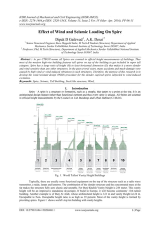
- 1. IOSR Journal of Mechanical and Civil Engineering (IOSR-JMCE) e-ISSN: 2278-1684,p-ISSN: 2320-334X, Volume 13, Issue 2 Ver. IV (Mar- Apr. 2016), PP 06-11 www.iosrjournals.org DOI: 10.9790/1684-1302040611 www.iosrjournals.org 6 | Page Effect of Wind and Seismic Loading On Spire Dipak D Gaikwad 1 , A.K. Desai 2 1 Senior Structural Engineer,Buro Happold India, M.Tech-R Student (Structure) Department of Applied Mechanics Sardar Vallabhbhai National Institute of Technology Surat-395007, India 2 Professor, Phd, M.Tech-(Structure), Department of Applied Mechanics Sardar Vallabhbhai National Institute of Technology Surat-395007, India Abstract : As per CTBUH norms all Spires are counted in official height measurements of buildings. Thus most of the modern high-rise building features tall spires on top of the building to get included in super tall category. Spire has a large ratio of height (H) to least horizontal dimension (D) that makes it a more slender and wind-sensitive than any other structures. In the past several years, many accidents and much damage were caused by high wind or wind-induced vibrations in such structures. Therefore, the purpose of this research is to develop the wind-resistant design (WRD) procedure for the slender, tapered spires subjected to wind-induced excitation. Keywords: Spire; Seismic; Tall Building; Stack like structure; Wind; I. Introduction Spire - A spire is a structure or formation, such as a steeple, that tapers to a point at the top. It is an architectural design feature rather than functional element and thus every spire is unique. All Spires are counted in official height measurements by the Council on Tall Buildings and Urban Habitat (CTBUH). Fig. 1. World Tallest Vanity Height Buildings Typically, there are usually some functional equipment on the top of the structure such as a radio wave transmitter, a radar, lamps and lanterns. The combination of the slender structure and the concentrated mass at the tip makes the structure fully aero elastic and unstable. For Burj Khalifa Vanity Height is 244 meter. This vanity height will be an impressive standalone skyscraper, If build in Europe, it will become continents' 11th tallest building. Another example is of Burj Al Arab, whose architectural height is 321 m and vanity Height is124 m. Occupiable to Non- Occupiable height ratio is as high as 39 percent. Most of the vanity height is formed by providing spires. Figure 1 shows world’s top ten building with vanity heights.
- 2. Paper Effect of Wind and Seismic Loading On Spire DOI: 10.9790/1684-1302040611 www.iosrjournals.org 7 | Page II. Parametric Study This paper presents the analysis process and design of a steel Spire in accordance with Indian code. The finite element software ETABS which can perform non-linear analysis was used for the analysis purposes. Initially presented the assumptions used for modelling, i.e. geometry, support conditions and loading calculations. Follows the simulation methodology at the particular software package and finally are presented the results of the analysis. For the modelling, finite shell elements are used. A. Description Of Spire The spire considered is of 100m height, single skin type with varying diameter as mentioned in table below. Fig. 2. Spire geometry Table 1-Summery Spire Geometry Part Length (m) Total Length (m) Initial Thickness (mm) Internal Model Diameter (mm) 1 12.00 0-12 18 4000 to 2000 2 16.00 12-28 14 3 12.00 28-40 12 4 60.00 40-100 8 Spire consists of 4 individual pieces of cylindrical shells of different thickness. The spire will be assembled on site using the appropriate screw connections. B. Software Analysis model In order to do dynamic wind analysis, spires time period and mode shapes needs to be calculated. Spire structure is modelled in finite element software ETABS using shell element and free vibrations analysis is carried out to obtain modal time period and mode shapes. Also time period is calculated as per empirical formula in IS-1893-(part-4) and compare with time period obtained from free vibration analysis. A 3D rendered view is show in Fig. 2.
- 3. Paper Effect of Wind and Seismic Loading On Spire DOI: 10.9790/1684-1302040611 www.iosrjournals.org 8 | Page Fig. 3. Mode shapes and Time Period of spire from ETABS analysis Spire descried in above section is analyzed and designed for all six wind zones and worst seismic zone- V. MATHCAD program is prepared to analyze and design the Spire. Results obtained are presented in following section. Table 2. Summary of Results Wind/Seismic Zone Shear Force (kN) % with V-55 Bending Moment (kN.m) % with V-55 V-55 1583 - 398661 - V-50 1294 81 328223 82 V-47 965 61 247926 62 V-39 731 46 189993 48 V-33 503 32 132493 33 Seismic Zone-5 0.25 2.52 964 0.25
- 4. Paper Effect of Wind and Seismic Loading On Spire DOI: 10.9790/1684-1302040611 www.iosrjournals.org 9 | Page Fig. 4. Shear force distriution alog heigh of spire for differet load cases Shear kN Height
- 5. Paper Effect of Wind and Seismic Loading On Spire DOI: 10.9790/1684-1302040611 www.iosrjournals.org 10 | Page Fig. 5. Beding moment distriution alog heigh of spire for differet load cases Summary of permissible and actual stress along the height of the spire for different wind zones is summarise as bellow. Moment kN.M Height
- 6. Paper Effect of Wind and Seismic Loading On Spire DOI: 10.9790/1684-1302040611 www.iosrjournals.org 11 | Page Table 3. Summary of Results Wind Speed V-33 V-39 V-44 V-47 V-50 V-55 Height Permissible stress Actual Stress Actual Stress Actual Stress Actual Stress Actual Stress Actual Stress 4 89.7 9.2 9.2 9.3 9.3 9.3 9.4 8 91.7 9.4 9.4 9.5 9.5 9.5 9.6 12 93.8 9.6 9.6 9.7 9.7 9.7 9.8 16 96 13.4 13.4 13.5 13.5 13.6 13.6 20 79.3 13.7 13.7 13.8 13.8 13.9 13.9 24 81.4 14 14 14.1 14.1 14.2 14.3 28 83.6 14.3 14.4 14.4 14.5 14.5 14.6 32 85.2 17.9 18 18.1 18.1 18.2 18.3 36 74.6 18.3 18.4 18.5 18.6 18.6 18.8 40 76 18.8 18.9 19 19 19.1 19.2 44 77.6 34.7 34.9 35.1 35.2 35.3 35.6 48 48.7 35.6 35.8 36 36.1 36.3 36.5 52 49.8 36.6 36.8 37 37.1 37.3 37.5 56 51 37.6 37.8 38 38.2 38.3 38.6 60 52.3 38.7 38.9 39.1 39.3 39.5 39.7 64 53.6 39.8 40 40.3 40.4 40.6 40.9 68 54.9 41 41.3 51.5 41.7 41.9 42.2 72 56.4 42.3 42.6 42.8 43 43.2 43.6 76 57.9 43.6 43.9 44.2 44.4 44.7 45 80 59.5 45.1 45.4 45.7 45.9 46.2 46.6 84 61.9 46.6 47 47.3 47.5 47.8 48.2 88 62.9 48.3 48.7 49 49.3 49.5 50 92 64.8 50.1 50.5 50.9 51.1 51.4 51.9 96 66.8 52 52.4 52.9 53.1 53.4 53.9 100 68.9 54.1 54.5 55 55.3 55.6 56.2 III. Conclusion It is found from analysis that, Time period calculated from empirical formula is nearly equals to period calculated free vibration analysis. Seismic forces for most sever zone are much lower than lowest wind zone. Though spire is safe for wind it may be unsafe for fatigue. This study will be carried out in next phase of study. In past many failures of engineered stack like structure are observed because of fatigue. Some work is already done but yet a generalized well established method for wind induced fatigue design is not available. Also there is scope for further work on application of damping devices specially tuned mass dampers to avoid the fatigue failures. Also it’s been observed that theoretical performance of TMD differs from actual performance and furthers work can be done to minimize this deviations. References [1]. Brian Breukelman, P. Eng.Challenging Vibration in Engineered Structures March 2004 Modern Steel Construction CAD rendering of TMD mass and pinnacle structure for Taipei 101. [2]. Ching-Wen Chien, Jing-Jong Jang, and Yi-Chao Li Wind resistance design of high mast structures, Journal of the Chinese Institute of Engineers, Vol. 33, No. 4, pp. 597-615 (2010) [3]. Ching-Wen Chien, Jing-Jong Jang, and Yi-Chao Li Case study of wind-resistant design and analysis of high mast structures based on different wind codes, Journal of Marine Science and Technology, Vol. 16, No. 4, pp. 275-287 (2008) [4]. Ching-Wen Chien, Jing-Jong Jang, and Yi-Chao Li Case study of wind-resistant design and analysis of high mast structures based on different wind codes, Journal of Marine Science and Technology, Vol. 16, No. 4, pp. 275-287 (2008) [5]. Daryl Boggs, Brent Wright, and Roy Denoon, Wind Engineering for the Las Vegas Stratosphere Tower, The sixth Asia-Pacific Conference on Wind Engineering, Secul,Korea,Septembe12-14;2005 [6]. H.W. Klein, W. Kaldenbach, A new vibration damping facility for steel chimneys [7]. John D. Holmes Response of cylindrical structures to vortex shedding in Natural Wind, 13th Australian Fluid Mechanics Conference Monash University, Australia,13-18,December 98 [8]. Leo Argiris Andrew Jackson, Patrick McCafferty Daniel Powell, Engineering the USA air force memorial, The Arup Journal 1/2007 [9]. M. G. Shaikh, H.A.M.I. Khan Governing Loads for Design of A tall RCC Chimney, IOSR Journal of Mechanical and Civil Engineering (IOSR-JMCE) ISSN: 2278-1684, PP: 12-19 www.iosrjournals.org [10]. Maria Pia Repetto and Giovanni Solari, Diagnosis of Fatigue collapses of slender structures due to aerodynamic wind actions, BBAA VI International Colloquium on: Bluff Bodies Aerodynamics & Applications Milano, Italy, July, 20-24 2008 [11]. Natthapong Areemit, Pennung Warnitchai, Vibration suppression of a 90mtall steel stack by using a high-damping tined mass damper, The Eighth East Asia-Pacific Conference on Structural Engineering and Construction 5-7 December 2001, Nanyang Technological University, Singapore [12]. Ranjith Chandunni, Farshad Berahman, The structural design of Almas Tower, Dubai, UAE, [13]. Svend Ole Hansen, Vortex-induced vibrations of structures, Structural Engineers World Congress 2007, November 2-7, 2007. Bangalore, India [14]. [14] WANG Zhong-wen, ZHU Hong-ping , MA Cun-ming, Effects of Tuned Mass Damper on Wind-Induced Vibration of Free Standing Pylon by Wind Tunnel Test, Vol. 17 NO.2 Journal 0/ Southwest Jitong University (English Edition) Apr. 2009 Article ID: 1005-2429(2009)02-0109-04