SlideShare a Scribd company logo
1 of 75
Design of Shaft
•
Prof. S. G. Kolgiri,
SBPCOE,Indapur
A shaft is a rotating member usually of circular cross-section (solid
or hollow), which transmits power and rotational motion.
Machine elements such as gears, pulleys (sheaves), flywheels,
clutches, and sprockets are mounted on the shaft and are used to
transmit power from the driving device (motor or engine) through a
machine.
Press fit, keys, dowel, pins and splines are used to attach these
machine elements on the shaft.
The shaft rotates on rolling contact bearings or bush bearings.
Various types of retaining rings, thrust bearings, grooves and steps
in the shaft are used to take up axial loads and locate the rotating
elements.
Couplings are used to transmit power from drive shaft (e.g., motor)
to the driven shaft (e.g. gearbox, wheels).
•
•
•
•
•
Prof. S. G. Kolgiri,
SBPCOE,Indapur
Talking Points
• Shaft?
• Shaft Design
• ASME Shaft Equations
• Design of Shaft for Torsional Rigidity
• Standard Sizes of Shafts
• Bending and Torsional Moments
The connecting shaft is loaded
primarily in torsion.
Prof. S. G. Kolgiri,
SBPCOE,Indapur
Prof. S. G. Kolgiri,
SBPCOE,Indapur
Introduction
A shaft is a rotating machine element which is used to transmit power from one place
to another. The power is delivered to the shaft by some tangential force and the
resultant torque (or twisting moment) set up within the shaft permits the power to be
transferredtovariousmachineslinkeduptotheshaft.
In order to transfer the power from one shaft to another, the various members such as
pulleys, gears etc., are mounted on it. These members along with the forces exerted
uponthemcausestheshafttobending.
In other words, we may say that a shaft is used for the transmission of torque and
bending moment. The various members are mounted on the shaft by means of keys
orsplines.
Notes:
1.The shafts are usually cylindrical, but may be square or cross-shaped in section.
Theyaresolidin cross-sectionbutsometimeshollowshafts arealsoused.
2.An axle, though similar in shape to the shaft, is a stationary machine element and is
used for the transmission of bending momentonly. It simply acts as a support for some
rotatingbodysuchashoistingdrum,acarwheeloraropesheave.
3.Aspindle is a short shaft that imparts motion either to a cutting tool (e.g. drill press
spindles) or toaworkpiece(e.g. lathespindles).
Prof. S. G. Kolgiri, SBPCOE,Indapur
Material Used for Shafts
Thematerialusedfor shaftsshouldhavethefollowing properties :
1.It shouldhavehighstrength.
2.It shouldhavegoodmachinability.
3.It shouldhavelownotchsensitivityfactor.
4.It shouldhavegoodheattreatmentproperties.
5.It shouldhavehighwear resistant properties.
Thematerialusedfor ordinaryshaftsis carbonsteelofgrades40C8, 45C8, 50C4
and50C12.
Themechanicalpropertiesof thesegradesof carbonsteelaregivenin thefollowing
table.
Whenashaftof highstrengthis required, thenanalloy steelsuchasnickel, nickel-chromium or
chrome-vanadiumsteel isused. Prof. S. G. Kolgiri, SBPCOE,Indapur
Prof. S. G. Kolgiri, SBPCOE,Indapur
Manufacturing of Shafts
Shafts aregenerallymanufacturedbyhotrolling andfinished to sizebycolddrawingor
turning andgrinding.Thecoldrolledshafts arestrongerthanhotrolledshafts butwith
higherresidualstresses.
Theresidual stresses maycausedistortion of the shaft whenit is machined,especially
whenslots or keyways are cut. Shafts of larger diameter areusually forgedand turned
to sizein alathe.
Prof. S. G. Kolgiri, SBPCOE,Indapur
Types of Shafts
Thefollowing twotypesof shaftsareimportantfromthesubjectpointof view:
1.Transmission shafts. These shafts transmit power between the source and the
machines absorbing power. The counter shafts, line shafts, over head shafts and all
factory shafts are transmission shafts. Since these shafts carry machine parts such as
pulleys,gearsetc.,thereforethey aresubjectedto bendingin addition totwisting.
2.Machine shafts. These shafts form an integral part of the machine itself. The crank
shaft isanexampleof machineshaft.
Prof. S. G. Kolgiri, SBPCOE,Indapur
Standard Sizes of Transmission Shafts
The standard sizes of transmission shafts are :
25 mm to 60 mm with 5 mm steps; 60 mm to 110 mm with 10 mm steps ;
110 mm to 140 mm with 15 mm steps ; and 140 mm to 500 mm with 20
mm steps.
The standard length of the shafts are 5 m, 6 m and 7 m.
Prof. S. G. Kolgiri, SBPCOE,Indapur
Stresses in Shafts
The following stresses are induced in the shafts :
1.Shear stresses due to the transmission of torque (i.e. due to torsional
load).
2.Bending stresses (tensile or compressive) due to the forces acting upon
machine elements like gears, pulleys etc. as well as due to the weight of
the shaft itself.
3. Stresses due to combined torsional and bending loads.
Prof. S. G. Kolgiri, SBPCOE,Indapur
Maximum Permissible Working
Stresses for Transmission Shafts
AccordingtoAmericanSocietyofMechanicalEngineers(ASME)codeforthedesignof
transmissionshafts, themaximumpermissibleworkingstressesin tensionorcompression
maybetakenas
(a) 112MPaforshaftswithout allowanceforkeyways.
(b) 84MPafor shaftswithallowanceforkeyways.
For shaftspurchased under definitephysicalspecifications,thepermissibletensilestress
(σt) maybetakenas60percentof theelastic limit in tension(σel), butnotmorethan36per
centof theultimatetensile strength(σu). Inother words,thepermissible tensile stress,
σt =0.6σel or 0.36σu, whichever isless.
Themaximumpermissibleshear stressmaybetakenas
(a) 56MPaforshaftswithoutallowancefor keyways.
(b) 42MPafor shaftswithallowanceforkeyways.
For shafts purchased under definite physical specifications, the permissible shear stress (τ)
maybe takenas 30 percent of the elastic limit in tension(σel) butnotmorethan18percent
oftheultimate tensile strength(σu). Inotherwords,thepermissible shearstress,
τ =0.3σel or 0.18σu, whichever isless.
Prof. S. G. Kolgiri, SBPCOE,Indapur
Design of Shafts
The shafts may be designed on the basis of
1. Strength, and 2. Rigidity and stiffness.
In designing shafts on the basis of strength, the following cases may be
considered :
(a) Shafts subjected to twisting moment or torque only,
(b) Shafts subjected to bending moment only,
(c) Shafts subjected to combined twisting and bending moments, and
(d)Shafts subjected to axial loads in addition to combined torsional and
bending loads.
We shall now discuss the above cases, in detail, in the following pages.
Shafts Subjected to Twisting
Moment Only
When the shaft is subjected to a twisting moment (or torque) only, then the
diameter of the shaft may be obtained by using the torsion equation. We
know that
...(i)
where
T = Twisting moment (or torque) acting upon the shaft,
J = Polar moment of inertia of the shaft about the axis of rotation,
τ = Torsional shear stress, and
r = Distance from neutral axis to the outer most fibre
= d / 2; where d is the diameter of the shaft.
Prof. S. G. Kolgiri, SBPCOE,Indapur
Weknowthat forround solidshaft, polar momentofinertia,
Theequation(i) maynowbewrittenas
...(ii)
Fromthis equation,wemaydeterminethediameterofroundsolidshaft( d).
Wealsoknowthat forhollow shaft, polarmomentofinertia,
wheredoanddi =Outsideandinside diameteroftheshaft, andr =do/ 2.
Substitutingthesevaluesinequation(i), wehave
...(iii)
Letk=Ratioofinside diameterandoutsidediameter oftheshaft
=di / do
Nowtheequation(iii) maybewrittenas
Prof. S. G. Kolgiri, SBPCOE,Indapur
...(iv)
Fromtheequations (iii) or(iv), theoutsideandinsidediameterofahollowshaftmaybe
determined.
It maybenotedthat
1. Thehollow shaftsare usuallyusedin marinework.Theseshafts are stronger perkg of
material andthey maybeforged ona mandrel, thus making the material morehomogeneous
thanwould bepossiblefor asolidshaft.
When ahollowshaft is to bemadeequalin strength to asolid shaft, the twisting momentof both
theshafts mustbesame.Inotherwords,forthesamematerialofboththeshafts,
Prof. S. G. Kolgiri, SBPCOE,Indapur
2.Thetwistingmoment(T) maybeobtained byusing thefollowing relation :
Weknowthat thepowertransmitted(in watts) bytheshaft,
where
Prof. S. G. Kolgiri, SBPCOE,Indapur
T=Twistingmoment inN-m, and
N=Speedof theshaft inr.p.m.
3. Incaseof belt drives, thetwistingmoment ( T) isgivenby
T=(T1–T2) R
where
T1andT2=Tensions in thetight sideandslack sideof thebelt respectively,and
R=Radius of thepulley.
Example 1
Alineshaft rotatingat 200r.p.m. is totransmit 20kW.Theshaft maybeassumedto bemadeof
mild steel withanallowableshearstress of 42MPa.Determine thediameter oftheshaft,
neglecting thebendingmoment ontheshaft.
Solution.
Given: N=200r.p.m. ; P=20kW=20×103W;τ =42MPa=42N/mm2
Let d=Diameter of theshaft.
Weknowthat torque transmittedbytheshaft,
We also know that torque transmitted by the shaft ( T ),
Prof. S. G. Kolgiri, SBPCOE,Indapur
Example 2.
A solid shaft is transmitting 1 MW at 240 r.p.m. Determine the diameter of the shaft
if the maximum torque transmitted exceeds the mean torque by 20%. Take the maximum
allowable shear stress as 60 MPa.
Solution.
Given : P = 1 MW = 1 × 10⁶ W ; N = 240 r.p.m. ; Tmax = 1.2 Tmean ;
τ = 60 MPa = 60 N/mm2
Let d = Diameter of the shaft.
We know that mean torque transmitted by the shaft,
Maximum torque transmitted,
Tmax = 1.2 Tmean = 1.2 × 39 784 × 10 3= 47 741 × 103 N-mm
We know that maximum torque transmitted (Tmax),
Prof. S. G. Kolgiri, SBPCOE,Indapur
Example 3.
Find the diameter of a solid steel shaft to transmit 20 kW at 200 r.p.m. The
ultimate shear stress for the steel may be taken as 360 MPa and a factor of safety as 8.
If a hollow shaft is to be used in place of the solid shaft, find the inside and outside
diameter when the ratio of inside to outside diameters is 0.5.
Solution. Given : P = 20 kW = 20 × 103 W ; N = 200 r.p.m. ; τu = 360 MPa = 360
N/mm2 ; F.S. = 8 ; k = di / do = 0.5
We know that the allowable shear stress,
Diameter of the solid shaft
Let d = Diameter of the solid shaft.
We know that torque transmitted by the shaft,
We also know that torque transmitted by the solid shaft (T),
Prof. S. G. Kolgiri, SBPCOE,Indapur
Diameter of hollow shaft
Let di = Inside diameter, and
do = Outside diameter.
We know that the torque transmitted by the hollow shaft ( T ),
Prof. S. G. Kolgiri, SBPCOE,Indapur
Shafts Subjected to Bending Moment Only
When the shaft is subjected to a bending moment only, then the maximum stress (tensile or
compressive) is given by the bending equation. We know that
...(i)
where M = Bending moment,
I = Moment of inertia of cross-sectional area of the shaft about the axis of rotation,
σb = Bending stress, and
y = Distance from neutral axis to the outer-most fibre.
We know that for a round solid shaft, moment of inertia,
Substituting these values in equation (i), we have
Prof. S. G. Kolgiri, SBPCOE,Indapur
From this equation, diameter of the solid shaft (d) may be obtained.
We also know that for a hollow shaft, moment of inertia,
Again substituting these values in equation (i), we have
From this equation, the outside diameter of the shaft (do) may be obtained.
Prof. S. G. Kolgiri, SBPCOE,Indapur
Example 4.
A pair of wheels of a railway wagon carries a load of 50 kN on each axle box, acting at
a distance of 100 mm outside the wheel base. The gauge of the rails is 1.4 m. Find the
diameter of the axle between the wheels, if the stress is not to exceed 100 MPa.
Solution.
Given : W = 50 kN = 50 × 103 N ; L = 100 mm ; x = 1.4 m ; σb = 100 MPa = 100 N/mm2
The axle with wheels is shown in Fig. 1.
A little consideration will show that the maximum bending moment acts on the wheels at
C and D. Therefore maximum bending moment,
*M = W.L = 50 × 103 × 100 = 5 × 10⁶ N-mm
The maximum B.M. may be obtained as follows :
RC = RD = 50 kN = 50 × 103 N
B.M. at A, MA = 0
B.M. at C, MC = 50 × 103 × 100 = 5 × 10⁶ N-mm
B.M. at D, MD = 50 × 103 × 1500 – 50 × 103 × 1400 = 5 × 10⁶ N-mm
B.M. at B, MB = 0 Prof. S. G. Kolgiri, SBPCOE,Indapur
Let d = Diameter of the axle.
We know that the maximum bending moment (M),
Prof. S. G. Kolgiri, SBPCOE,Indapur
Shafts Subjected to Combined Twisting Moment and Bending Moment
When the shaft is subjected to combined twisting moment and bending moment, then the
shaft must be designed on the basis of the two moments simultaneously. Various theories
have been suggested to account for the elastic failure of the materials when they are
subjected to various types of combined stresses. The following two theories are important
from the subject point of view :
1.Maximum shear stress theory or Guest's theory. It is used for ductile materials such
as mild steel.
2.Maximum normal stress theory or Rankine’s theory. It is used for brittle materials
such as cast iron.
Let τ = Shear stress induced due to twisting moment, and
σb = Bending stress (tensile or compressive) induced due to bending moment.
According to maximum shear stress theory, the maximum shear stress in the shaft,
Prof. S. G. Kolgiri, SBPCOE,Indapur
Substituting the values of τ and σb from Art. 14.9 and Art. 14.10, we have
Prof. S. G. Kolgiri, SBPCOE,Indapur
Example 5.
A solid circular shaft is subjected to a bending moment of 3000 N-m and a torque of
10 000 N-m. The shaft is made of 45 C 8 steel having ultimate tensile stress of 700 MPa and
a ultimate shear stress of 500 MPa. Assuming a factor of safety as 6, determine the diameter
of the shaft.
Prof. S. G. Kolgiri, SBPCOE,Indapur
Example 6.
A shaft supported at the ends in ball bearings carries a straight tooth spur gear
at its mid span and is to transmit 7.5 kW at 300 r.p.m. The pitch circle diameter of the
gear is 150 mm. The distances between the centre line of bearings and gear are 100 mm
each. If the shaft is made of steel and the allowable shear stress is 45 MPa, determine
the diameter of the shaft. Show in a sketch how the gear will be mounted on the shaft;
also indicate the ends where the bearings will be mounted?
The pressure angle of the gear may be taken as 20°.
Prof. S. G. Kolgiri, SBPCOE,Indapur
Example 8. A line shaft is driven by means of a motor placed vertically below it. The pulley
on the line shaft is 1.5 metre in diameter and has belt tensions 5.4 kN and 1.8 kN on the tight
side and slack side of the belt respectively. Both these tensions may be assumed to be vertical.
If the pulley be overhang from the shaft, the distance of the centre line of the pulley from the
centre line of the bearing being 400 mm, find the diameter of the shaft. Assuming maximum
allowable shear stress of 42 MPa.
Solution .
Given : D = 1.5 m or R = 0.75 m; T1 = 5.4 kN = 5400 N ; T2 = 1.8 kN = 1800 N ;
L = 400 mm ; τ = 42 MPa = 42 N/mm2
A line shaft with a pulley is shown in Fig 14.4.
We know that torque transmitted by the shaft,
T = (T1 – T2) R = (5400 – 1800) 0.75 = 2700 N-m
= 2700 × 103 N-mm
Prof. S. G. Kolgiri, SBPCOE,Indapur
Shafts Subjected to Fluctuating Loads
In the previous articles we have assumed that the shaft is subjected to constant torque
and bending moment. But in actual practice, the shafts are subjected to fluctuating
torque and bending moments. In order to design such shafts like line shafts and counter
shafts, the combined shock and fatigue factors must be taken into account for the
computed twisting moment (T ) and bending moment (M ). Thus for a shaftsubjected to
combined bending and torsion, the equivalent twisting moment,
and equivalent bending moment,
where
Prof. S. G. Kolgiri, SBPCOE,Indapur
Km = Combined shock and fatigue factor for bending, and
Kt = Combined shock and fatigue factor for torsion.
The following table shows the recommended values for Km and Kt.
Prof. S. G. Kolgiri, SBPCOE,Indapur
Shafts Subjected to Axial Load in addition to
Combined Torsion and Bending Loads
Prof. S. G. Kolgiri, SBPCOE,Indapur
Design of Shafts on the basis of Rigidity
Prof. S. G. Kolgiri, SBPCOE,Indapur
Combined bending and torsion loads on shaft:
Shaft carrying gears.
From power and rpm find the torque (T), which gives rise to shear stress.
From Torque (T) and diameter (d), find Ft = 2T/d. From Ft and pressure
angles of gears you can find Fr and Fa.
Fr and Ft are orthogonal to each other and are both transverse forces to
the shaft axis, which will give rise to normal bending stress in the shaft.
When shaft rotates, bending stress changes from tensile to compressive
and then compressive to tensile, ie, completely reversing state of stress.
Fa will give rise to normal axial stress in the shaft.
Prof. S. G. Kolgiri,
SBPCOE,Indapur
Loads on shaft due to pulleys
Pulley torque (T) = Difference in belt
tensions in the tight (t1) and slack (t2)
sides of a pulley times the radius (r), ie
T = (t1-t2)xr
Left pulley torque
Prof. S. G. Kolgiri,
SBPCOE,Indapur
FV2
T1 = (7200-2700)x380=1,710,000 N-mm
Right pulley has exactly equal and
opposite torque:
T2 = (6750-2250)x380=1,710,000 N-mm
Bending forces in vertical (Fv) and horizontal (FH) directions:
At the left pulley: FV1=900N; FH1=7200+2700 = 9900N
At the right pulley: FV2=900+6750+2250=9900N; FH2=0
From Horizontal forces (FH) and vertical
forces (Fv), Bending moments MH & MV are
drawn separately.
Then the resultant moments at various
points on the shaft can be found from
Torque and Bending moment diagrams for the pulley
system
R H V
M 2
 M 2
M 
FH
9900N
2,227,500
MH
FV
900N 9900N
M V
2,227,500
911,250
T1 T2
Torque diag.
1,710,000 N-mm
Re5
sultant bending moment
2,227,500
2,406,68
V
H
R
M 2
 M 2
M 
The section of shaft where the left pulley
is located has obviously the highest
combination of Torque (1,710,000 N-mm)
and Bending moment (2,406,685 N-mm)
Prof. S. G. Kolgiri,
SBPCOE,Indapur
Prof. S. G. Kolgiri,
SBPCOE,Indapur
Power, toque & speed
For linear motion:
Power = F.v (force x velocity)
For rotational motion
Power P = Torque x angular velocity
= T (in-lb). rad/sec) in-lb/sec
= T.(  n/60) in-lb/sec [n=rpm]
= T.(  n/(60*12*550)) HP [HP=550 ft-lb/sec]
= T.n/63,025 HP
or, T= 63,025HP/n (in-lb), where n = rpm
Similarly, T= 9,550,000kW/n (N-mm), where n = rpm
Principal Normal Stresses and Max Distortion Energy
Failure criterion for non-rotating shafts
2
2
1
2
2


 
 2 
 
2
 
 2 
 
2
 2
and S  
S  
The stress at a point on the shaft is normal stress
() in X direction and shear stress  in XY plane.
From Mohr Circle:
Max Distortion Energy theory:

2
1
 S2
 S S
2 1 2
S2 

 
fs 
yp
 N 
 S
Putting values of S1 & S2 and simplifying:
 3 2
Prof. S. G. Kolgiri,
SBPCOE,Indapur
 2


2

  yp
 N 
 S
This is the design
fs  equation for non
rotating shaft
Design of rotating shafts and fatigue consideration
e
The most frequently encountered stress situation for a
rotating shaft is to have completely reversed bending and
steady torsional stress. In other situations, a shaft may hav
a reversed torsional stress along with reversed bending
stress.
The most generalized situation the rotating shaft may
have both steady and cyclic components of bending
stress (av,r) and torsional stress (av,r).
From Soderberg’s fatigue criterion, the equivalent
static bending and torsional stresses are:
Using these equivalent static stresses in our static
design equation, the equation for rotating shaft is:
Prof. S. G. Kolgiri,
SBPCOE,Indapur
Bearing mounting considerations
and stress concentration
Prof. S. G. Kolgiri,
SBPCOE,Indapur
Conventional retaining (or snap) rings fit
in grooves and take axial load, but groves
cause stress concentration in shaft
Retaining rings are
standardized items,
available in various
standard sizes with
various axial load
capacities.
Prof. S. G. Kolgiri,
SBPCOE,Indapur
Push type retaining rings – no grooves
required, less stress concentration, but
less axial support
Prof. S. G. Kolgiri,
SBPCOE,Indapur
Various types of keys for transmitting
torque
Prof. S. G. Kolgiri,
SBPCOE,Indapur
Other common types of keys
Prof. S. G. Kolgiri,
SBPCOE,Indapur
Various types of collar pins
Prof. S. G. Kolgiri,
SBPCOE,Indapur
Integrated splines in hubs and shafts
allow axial motion and transmits torque
All keys, pins and splines give rise to stress
concentration in the hub and shaft
Prof. S. G. Kolgiri,
SBPCOE,Indapur

More Related Content

What's hot

1.2 terminology of spur gear
1.2 terminology of spur gear1.2 terminology of spur gear
1.2 terminology of spur gearKiran Wakchaure
 
Bearings machine design.pptx
Bearings machine design.pptxBearings machine design.pptx
Bearings machine design.pptxPankajChhabra31
 
10. Rolling Contact Bearing.pdf
10. Rolling Contact Bearing.pdf10. Rolling Contact Bearing.pdf
10. Rolling Contact Bearing.pdfsaiashwindran
 
MODELLING AND STRESS ANALYSIS OF COLUMN BRACKET FOR ROTARY JIB CRANE
MODELLING AND STRESS ANALYSIS OF COLUMN BRACKET FOR ROTARY JIB CRANE MODELLING AND STRESS ANALYSIS OF COLUMN BRACKET FOR ROTARY JIB CRANE
MODELLING AND STRESS ANALYSIS OF COLUMN BRACKET FOR ROTARY JIB CRANE IAEME Publication
 
Brakes and dynamometer knw
Brakes and dynamometer knwBrakes and dynamometer knw
Brakes and dynamometer knwKiran Wakchaure
 
gear trains ppt
gear trains pptgear trains ppt
gear trains pptBaji Bujji
 
Power Transmission Devices
Power Transmission DevicesPower Transmission Devices
Power Transmission DevicesNitin Shekapure
 
Introduction & Design of Bevel Gears
Introduction & Design of Bevel GearsIntroduction & Design of Bevel Gears
Introduction & Design of Bevel GearsDhrumit Patel
 
Design of Flat belt, V belt and chain drives
Design of Flat belt, V belt and chain drivesDesign of Flat belt, V belt and chain drives
Design of Flat belt, V belt and chain drivesDr. L K Bhagi
 
Power transmission elements BASIC MECHANICAL ENGINEERING SEM-II
Power transmission  elements BASIC MECHANICAL ENGINEERING  SEM-IIPower transmission  elements BASIC MECHANICAL ENGINEERING  SEM-II
Power transmission elements BASIC MECHANICAL ENGINEERING SEM-II9960204020
 
5 shaft shafts subjected to combined twisting moment and bending moment
5 shaft   shafts subjected to combined twisting moment and bending moment5 shaft   shafts subjected to combined twisting moment and bending moment
5 shaft shafts subjected to combined twisting moment and bending momentDr.R. SELVAM
 

What's hot (20)

Worm gear
Worm gearWorm gear
Worm gear
 
lever
leverlever
lever
 
Gear Quality Parameters
Gear Quality ParametersGear Quality Parameters
Gear Quality Parameters
 
7 universal joint
7 universal joint7 universal joint
7 universal joint
 
Shaft
ShaftShaft
Shaft
 
1.2 terminology of spur gear
1.2 terminology of spur gear1.2 terminology of spur gear
1.2 terminology of spur gear
 
Bearings machine design.pptx
Bearings machine design.pptxBearings machine design.pptx
Bearings machine design.pptx
 
10. Rolling Contact Bearing.pdf
10. Rolling Contact Bearing.pdf10. Rolling Contact Bearing.pdf
10. Rolling Contact Bearing.pdf
 
MODELLING AND STRESS ANALYSIS OF COLUMN BRACKET FOR ROTARY JIB CRANE
MODELLING AND STRESS ANALYSIS OF COLUMN BRACKET FOR ROTARY JIB CRANE MODELLING AND STRESS ANALYSIS OF COLUMN BRACKET FOR ROTARY JIB CRANE
MODELLING AND STRESS ANALYSIS OF COLUMN BRACKET FOR ROTARY JIB CRANE
 
Brakes and dynamometer knw
Brakes and dynamometer knwBrakes and dynamometer knw
Brakes and dynamometer knw
 
7-Gear Measurement-P1.pdf
7-Gear Measurement-P1.pdf7-Gear Measurement-P1.pdf
7-Gear Measurement-P1.pdf
 
Chain drives
Chain drivesChain drives
Chain drives
 
gear trains ppt
gear trains pptgear trains ppt
gear trains ppt
 
Power Transmission Devices
Power Transmission DevicesPower Transmission Devices
Power Transmission Devices
 
Introduction & Design of Bevel Gears
Introduction & Design of Bevel GearsIntroduction & Design of Bevel Gears
Introduction & Design of Bevel Gears
 
Design of Flat belt, V belt and chain drives
Design of Flat belt, V belt and chain drivesDesign of Flat belt, V belt and chain drives
Design of Flat belt, V belt and chain drives
 
Gear train
Gear trainGear train
Gear train
 
Classification of Bearings
Classification of BearingsClassification of Bearings
Classification of Bearings
 
Power transmission elements BASIC MECHANICAL ENGINEERING SEM-II
Power transmission  elements BASIC MECHANICAL ENGINEERING  SEM-IIPower transmission  elements BASIC MECHANICAL ENGINEERING  SEM-II
Power transmission elements BASIC MECHANICAL ENGINEERING SEM-II
 
5 shaft shafts subjected to combined twisting moment and bending moment
5 shaft   shafts subjected to combined twisting moment and bending moment5 shaft   shafts subjected to combined twisting moment and bending moment
5 shaft shafts subjected to combined twisting moment and bending moment
 

Similar to unit2designofshaft-170719110901 (1) (1).pptx

Similar to unit2designofshaft-170719110901 (1) (1).pptx (20)

Unit 2 design of shaft
Unit 2 design of shaftUnit 2 design of shaft
Unit 2 design of shaft
 
Poros
PorosPoros
Poros
 
Lecture_2.pdf
Lecture_2.pdfLecture_2.pdf
Lecture_2.pdf
 
Unit 2 Shafts and Coupling.pptx
Unit 2 Shafts and Coupling.pptxUnit 2 Shafts and Coupling.pptx
Unit 2 Shafts and Coupling.pptx
 
chapter3_Shaft.ppt
chapter3_Shaft.pptchapter3_Shaft.ppt
chapter3_Shaft.ppt
 
Design of machine elements -unit2.pptx
Design of machine elements -unit2.pptxDesign of machine elements -unit2.pptx
Design of machine elements -unit2.pptx
 
Design of machine element II.pptx
Design of machine element II.pptxDesign of machine element II.pptx
Design of machine element II.pptx
 
99999599.pptx
99999599.pptx99999599.pptx
99999599.pptx
 
Shaft under combined loading
Shaft under combined loadingShaft under combined loading
Shaft under combined loading
 
3 shaft stress in shafts
3 shaft   stress in shafts3 shaft   stress in shafts
3 shaft stress in shafts
 
SHAFTS And Its Mechanical Properties.pptx
SHAFTS And Its Mechanical Properties.pptxSHAFTS And Its Mechanical Properties.pptx
SHAFTS And Its Mechanical Properties.pptx
 
DESIGN OF SOLID TRANSMISSION SHAFT
DESIGN OF SOLID TRANSMISSION SHAFTDESIGN OF SOLID TRANSMISSION SHAFT
DESIGN OF SOLID TRANSMISSION SHAFT
 
Design of.pptx
Design of.pptxDesign of.pptx
Design of.pptx
 
Final year project
Final year projectFinal year project
Final year project
 
Simple torsion equation
Simple torsion equationSimple torsion equation
Simple torsion equation
 
Worm gears
Worm gearsWorm gears
Worm gears
 
Flywheel.ppt
Flywheel.pptFlywheel.ppt
Flywheel.ppt
 
Unit 2 Design Of Shafts Keys and Couplings
Unit 2 Design Of Shafts Keys and CouplingsUnit 2 Design Of Shafts Keys and Couplings
Unit 2 Design Of Shafts Keys and Couplings
 
E1303072935
E1303072935E1303072935
E1303072935
 
Unit 7-60
Unit 7-60Unit 7-60
Unit 7-60
 

More from HarikumarA4

Belt Drives_2.pdf
Belt Drives_2.pdfBelt Drives_2.pdf
Belt Drives_2.pdfHarikumarA4
 
Belt Drives_1.pptx
Belt Drives_1.pptxBelt Drives_1.pptx
Belt Drives_1.pptxHarikumarA4
 
BRAKE_SYSTEM.pptx
BRAKE_SYSTEM.pptxBRAKE_SYSTEM.pptx
BRAKE_SYSTEM.pptxHarikumarA4
 
Stresses in flywheel rim.pptx
Stresses in flywheel rim.pptxStresses in flywheel rim.pptx
Stresses in flywheel rim.pptxHarikumarA4
 
V-belt Drives.pptx
V-belt Drives.pptxV-belt Drives.pptx
V-belt Drives.pptxHarikumarA4
 
Sliding-Contact-Bearings.ppt
Sliding-Contact-Bearings.pptSliding-Contact-Bearings.ppt
Sliding-Contact-Bearings.pptHarikumarA4
 
pp-chapter 7.ppt
pp-chapter 7.pptpp-chapter 7.ppt
pp-chapter 7.pptHarikumarA4
 
engineering-graphics.pdf
engineering-graphics.pdfengineering-graphics.pdf
engineering-graphics.pdfHarikumarA4
 

More from HarikumarA4 (10)

Belt Drives_2.pdf
Belt Drives_2.pdfBelt Drives_2.pdf
Belt Drives_2.pdf
 
Belt Drives_1.pptx
Belt Drives_1.pptxBelt Drives_1.pptx
Belt Drives_1.pptx
 
PPT- CDT-8.pptx
PPT- CDT-8.pptxPPT- CDT-8.pptx
PPT- CDT-8.pptx
 
clutch.ppt
clutch.pptclutch.ppt
clutch.ppt
 
BRAKE_SYSTEM.pptx
BRAKE_SYSTEM.pptxBRAKE_SYSTEM.pptx
BRAKE_SYSTEM.pptx
 
Stresses in flywheel rim.pptx
Stresses in flywheel rim.pptxStresses in flywheel rim.pptx
Stresses in flywheel rim.pptx
 
V-belt Drives.pptx
V-belt Drives.pptxV-belt Drives.pptx
V-belt Drives.pptx
 
Sliding-Contact-Bearings.ppt
Sliding-Contact-Bearings.pptSliding-Contact-Bearings.ppt
Sliding-Contact-Bearings.ppt
 
pp-chapter 7.ppt
pp-chapter 7.pptpp-chapter 7.ppt
pp-chapter 7.ppt
 
engineering-graphics.pdf
engineering-graphics.pdfengineering-graphics.pdf
engineering-graphics.pdf
 

Recently uploaded

microprocessor 8085 and its interfacing
microprocessor 8085  and its interfacingmicroprocessor 8085  and its interfacing
microprocessor 8085 and its interfacingjaychoudhary37
 
Oxy acetylene welding presentation note.
Oxy acetylene welding presentation note.Oxy acetylene welding presentation note.
Oxy acetylene welding presentation note.eptoze12
 
VICTOR MAESTRE RAMIREZ - Planetary Defender on NASA's Double Asteroid Redirec...
VICTOR MAESTRE RAMIREZ - Planetary Defender on NASA's Double Asteroid Redirec...VICTOR MAESTRE RAMIREZ - Planetary Defender on NASA's Double Asteroid Redirec...
VICTOR MAESTRE RAMIREZ - Planetary Defender on NASA's Double Asteroid Redirec...VICTOR MAESTRE RAMIREZ
 
IVE Industry Focused Event - Defence Sector 2024
IVE Industry Focused Event - Defence Sector 2024IVE Industry Focused Event - Defence Sector 2024
IVE Industry Focused Event - Defence Sector 2024Mark Billinghurst
 
CCS355 Neural Network & Deep Learning UNIT III notes and Question bank .pdf
CCS355 Neural Network & Deep Learning UNIT III notes and Question bank .pdfCCS355 Neural Network & Deep Learning UNIT III notes and Question bank .pdf
CCS355 Neural Network & Deep Learning UNIT III notes and Question bank .pdfAsst.prof M.Gokilavani
 
What are the advantages and disadvantages of membrane structures.pptx
What are the advantages and disadvantages of membrane structures.pptxWhat are the advantages and disadvantages of membrane structures.pptx
What are the advantages and disadvantages of membrane structures.pptxwendy cai
 
Microscopic Analysis of Ceramic Materials.pptx
Microscopic Analysis of Ceramic Materials.pptxMicroscopic Analysis of Ceramic Materials.pptx
Microscopic Analysis of Ceramic Materials.pptxpurnimasatapathy1234
 
Introduction to Microprocesso programming and interfacing.pptx
Introduction to Microprocesso programming and interfacing.pptxIntroduction to Microprocesso programming and interfacing.pptx
Introduction to Microprocesso programming and interfacing.pptxvipinkmenon1
 
Model Call Girl in Narela Delhi reach out to us at 🔝8264348440🔝
Model Call Girl in Narela Delhi reach out to us at 🔝8264348440🔝Model Call Girl in Narela Delhi reach out to us at 🔝8264348440🔝
Model Call Girl in Narela Delhi reach out to us at 🔝8264348440🔝soniya singh
 
ZXCTN 5804 / ZTE PTN / ZTE POTN / ZTE 5804 PTN / ZTE POTN 5804 ( 100/200 GE Z...
ZXCTN 5804 / ZTE PTN / ZTE POTN / ZTE 5804 PTN / ZTE POTN 5804 ( 100/200 GE Z...ZXCTN 5804 / ZTE PTN / ZTE POTN / ZTE 5804 PTN / ZTE POTN 5804 ( 100/200 GE Z...
ZXCTN 5804 / ZTE PTN / ZTE POTN / ZTE 5804 PTN / ZTE POTN 5804 ( 100/200 GE Z...ZTE
 
power system scada applications and uses
power system scada applications and usespower system scada applications and uses
power system scada applications and usesDevarapalliHaritha
 
Past, Present and Future of Generative AI
Past, Present and Future of Generative AIPast, Present and Future of Generative AI
Past, Present and Future of Generative AIabhishek36461
 
Current Transformer Drawing and GTP for MSETCL
Current Transformer Drawing and GTP for MSETCLCurrent Transformer Drawing and GTP for MSETCL
Current Transformer Drawing and GTP for MSETCLDeelipZope
 
HARMONY IN THE HUMAN BEING - Unit-II UHV-2
HARMONY IN THE HUMAN BEING - Unit-II UHV-2HARMONY IN THE HUMAN BEING - Unit-II UHV-2
HARMONY IN THE HUMAN BEING - Unit-II UHV-2RajaP95
 
APPLICATIONS-AC/DC DRIVES-OPERATING CHARACTERISTICS
APPLICATIONS-AC/DC DRIVES-OPERATING CHARACTERISTICSAPPLICATIONS-AC/DC DRIVES-OPERATING CHARACTERISTICS
APPLICATIONS-AC/DC DRIVES-OPERATING CHARACTERISTICSKurinjimalarL3
 

Recently uploaded (20)

microprocessor 8085 and its interfacing
microprocessor 8085  and its interfacingmicroprocessor 8085  and its interfacing
microprocessor 8085 and its interfacing
 
★ CALL US 9953330565 ( HOT Young Call Girls In Badarpur delhi NCR
★ CALL US 9953330565 ( HOT Young Call Girls In Badarpur delhi NCR★ CALL US 9953330565 ( HOT Young Call Girls In Badarpur delhi NCR
★ CALL US 9953330565 ( HOT Young Call Girls In Badarpur delhi NCR
 
Oxy acetylene welding presentation note.
Oxy acetylene welding presentation note.Oxy acetylene welding presentation note.
Oxy acetylene welding presentation note.
 
VICTOR MAESTRE RAMIREZ - Planetary Defender on NASA's Double Asteroid Redirec...
VICTOR MAESTRE RAMIREZ - Planetary Defender on NASA's Double Asteroid Redirec...VICTOR MAESTRE RAMIREZ - Planetary Defender on NASA's Double Asteroid Redirec...
VICTOR MAESTRE RAMIREZ - Planetary Defender on NASA's Double Asteroid Redirec...
 
IVE Industry Focused Event - Defence Sector 2024
IVE Industry Focused Event - Defence Sector 2024IVE Industry Focused Event - Defence Sector 2024
IVE Industry Focused Event - Defence Sector 2024
 
Call Us -/9953056974- Call Girls In Vikaspuri-/- Delhi NCR
Call Us -/9953056974- Call Girls In Vikaspuri-/- Delhi NCRCall Us -/9953056974- Call Girls In Vikaspuri-/- Delhi NCR
Call Us -/9953056974- Call Girls In Vikaspuri-/- Delhi NCR
 
CCS355 Neural Network & Deep Learning UNIT III notes and Question bank .pdf
CCS355 Neural Network & Deep Learning UNIT III notes and Question bank .pdfCCS355 Neural Network & Deep Learning UNIT III notes and Question bank .pdf
CCS355 Neural Network & Deep Learning UNIT III notes and Question bank .pdf
 
What are the advantages and disadvantages of membrane structures.pptx
What are the advantages and disadvantages of membrane structures.pptxWhat are the advantages and disadvantages of membrane structures.pptx
What are the advantages and disadvantages of membrane structures.pptx
 
Microscopic Analysis of Ceramic Materials.pptx
Microscopic Analysis of Ceramic Materials.pptxMicroscopic Analysis of Ceramic Materials.pptx
Microscopic Analysis of Ceramic Materials.pptx
 
Introduction to Microprocesso programming and interfacing.pptx
Introduction to Microprocesso programming and interfacing.pptxIntroduction to Microprocesso programming and interfacing.pptx
Introduction to Microprocesso programming and interfacing.pptx
 
Model Call Girl in Narela Delhi reach out to us at 🔝8264348440🔝
Model Call Girl in Narela Delhi reach out to us at 🔝8264348440🔝Model Call Girl in Narela Delhi reach out to us at 🔝8264348440🔝
Model Call Girl in Narela Delhi reach out to us at 🔝8264348440🔝
 
ZXCTN 5804 / ZTE PTN / ZTE POTN / ZTE 5804 PTN / ZTE POTN 5804 ( 100/200 GE Z...
ZXCTN 5804 / ZTE PTN / ZTE POTN / ZTE 5804 PTN / ZTE POTN 5804 ( 100/200 GE Z...ZXCTN 5804 / ZTE PTN / ZTE POTN / ZTE 5804 PTN / ZTE POTN 5804 ( 100/200 GE Z...
ZXCTN 5804 / ZTE PTN / ZTE POTN / ZTE 5804 PTN / ZTE POTN 5804 ( 100/200 GE Z...
 
power system scada applications and uses
power system scada applications and usespower system scada applications and uses
power system scada applications and uses
 
9953056974 Call Girls In South Ex, Escorts (Delhi) NCR.pdf
9953056974 Call Girls In South Ex, Escorts (Delhi) NCR.pdf9953056974 Call Girls In South Ex, Escorts (Delhi) NCR.pdf
9953056974 Call Girls In South Ex, Escorts (Delhi) NCR.pdf
 
young call girls in Rajiv Chowk🔝 9953056974 🔝 Delhi escort Service
young call girls in Rajiv Chowk🔝 9953056974 🔝 Delhi escort Serviceyoung call girls in Rajiv Chowk🔝 9953056974 🔝 Delhi escort Service
young call girls in Rajiv Chowk🔝 9953056974 🔝 Delhi escort Service
 
Past, Present and Future of Generative AI
Past, Present and Future of Generative AIPast, Present and Future of Generative AI
Past, Present and Future of Generative AI
 
Current Transformer Drawing and GTP for MSETCL
Current Transformer Drawing and GTP for MSETCLCurrent Transformer Drawing and GTP for MSETCL
Current Transformer Drawing and GTP for MSETCL
 
HARMONY IN THE HUMAN BEING - Unit-II UHV-2
HARMONY IN THE HUMAN BEING - Unit-II UHV-2HARMONY IN THE HUMAN BEING - Unit-II UHV-2
HARMONY IN THE HUMAN BEING - Unit-II UHV-2
 
APPLICATIONS-AC/DC DRIVES-OPERATING CHARACTERISTICS
APPLICATIONS-AC/DC DRIVES-OPERATING CHARACTERISTICSAPPLICATIONS-AC/DC DRIVES-OPERATING CHARACTERISTICS
APPLICATIONS-AC/DC DRIVES-OPERATING CHARACTERISTICS
 
Exploring_Network_Security_with_JA3_by_Rakesh Seal.pptx
Exploring_Network_Security_with_JA3_by_Rakesh Seal.pptxExploring_Network_Security_with_JA3_by_Rakesh Seal.pptx
Exploring_Network_Security_with_JA3_by_Rakesh Seal.pptx
 

unit2designofshaft-170719110901 (1) (1).pptx

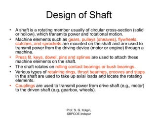
  • 1. Design of Shaft • Prof. S. G. Kolgiri, SBPCOE,Indapur A shaft is a rotating member usually of circular cross-section (solid or hollow), which transmits power and rotational motion. Machine elements such as gears, pulleys (sheaves), flywheels, clutches, and sprockets are mounted on the shaft and are used to transmit power from the driving device (motor or engine) through a machine. Press fit, keys, dowel, pins and splines are used to attach these machine elements on the shaft. The shaft rotates on rolling contact bearings or bush bearings. Various types of retaining rings, thrust bearings, grooves and steps in the shaft are used to take up axial loads and locate the rotating elements. Couplings are used to transmit power from drive shaft (e.g., motor) to the driven shaft (e.g. gearbox, wheels). • • • • •
  • 2. Prof. S. G. Kolgiri, SBPCOE,Indapur Talking Points • Shaft? • Shaft Design • ASME Shaft Equations • Design of Shaft for Torsional Rigidity • Standard Sizes of Shafts • Bending and Torsional Moments
  • 3. The connecting shaft is loaded primarily in torsion. Prof. S. G. Kolgiri, SBPCOE,Indapur
  • 4. Prof. S. G. Kolgiri, SBPCOE,Indapur Introduction A shaft is a rotating machine element which is used to transmit power from one place to another. The power is delivered to the shaft by some tangential force and the resultant torque (or twisting moment) set up within the shaft permits the power to be transferredtovariousmachineslinkeduptotheshaft. In order to transfer the power from one shaft to another, the various members such as pulleys, gears etc., are mounted on it. These members along with the forces exerted uponthemcausestheshafttobending. In other words, we may say that a shaft is used for the transmission of torque and bending moment. The various members are mounted on the shaft by means of keys orsplines.
  • 5. Notes: 1.The shafts are usually cylindrical, but may be square or cross-shaped in section. Theyaresolidin cross-sectionbutsometimeshollowshafts arealsoused. 2.An axle, though similar in shape to the shaft, is a stationary machine element and is used for the transmission of bending momentonly. It simply acts as a support for some rotatingbodysuchashoistingdrum,acarwheeloraropesheave. 3.Aspindle is a short shaft that imparts motion either to a cutting tool (e.g. drill press spindles) or toaworkpiece(e.g. lathespindles). Prof. S. G. Kolgiri, SBPCOE,Indapur
  • 6. Material Used for Shafts Thematerialusedfor shaftsshouldhavethefollowing properties : 1.It shouldhavehighstrength. 2.It shouldhavegoodmachinability. 3.It shouldhavelownotchsensitivityfactor. 4.It shouldhavegoodheattreatmentproperties. 5.It shouldhavehighwear resistant properties. Thematerialusedfor ordinaryshaftsis carbonsteelofgrades40C8, 45C8, 50C4 and50C12. Themechanicalpropertiesof thesegradesof carbonsteelaregivenin thefollowing table. Whenashaftof highstrengthis required, thenanalloy steelsuchasnickel, nickel-chromium or chrome-vanadiumsteel isused. Prof. S. G. Kolgiri, SBPCOE,Indapur
  • 7. Prof. S. G. Kolgiri, SBPCOE,Indapur Manufacturing of Shafts Shafts aregenerallymanufacturedbyhotrolling andfinished to sizebycolddrawingor turning andgrinding.Thecoldrolledshafts arestrongerthanhotrolledshafts butwith higherresidualstresses. Theresidual stresses maycausedistortion of the shaft whenit is machined,especially whenslots or keyways are cut. Shafts of larger diameter areusually forgedand turned to sizein alathe.
  • 8. Prof. S. G. Kolgiri, SBPCOE,Indapur Types of Shafts Thefollowing twotypesof shaftsareimportantfromthesubjectpointof view: 1.Transmission shafts. These shafts transmit power between the source and the machines absorbing power. The counter shafts, line shafts, over head shafts and all factory shafts are transmission shafts. Since these shafts carry machine parts such as pulleys,gearsetc.,thereforethey aresubjectedto bendingin addition totwisting. 2.Machine shafts. These shafts form an integral part of the machine itself. The crank shaft isanexampleof machineshaft.
  • 9. Prof. S. G. Kolgiri, SBPCOE,Indapur Standard Sizes of Transmission Shafts The standard sizes of transmission shafts are : 25 mm to 60 mm with 5 mm steps; 60 mm to 110 mm with 10 mm steps ; 110 mm to 140 mm with 15 mm steps ; and 140 mm to 500 mm with 20 mm steps. The standard length of the shafts are 5 m, 6 m and 7 m.
  • 10. Prof. S. G. Kolgiri, SBPCOE,Indapur Stresses in Shafts The following stresses are induced in the shafts : 1.Shear stresses due to the transmission of torque (i.e. due to torsional load). 2.Bending stresses (tensile or compressive) due to the forces acting upon machine elements like gears, pulleys etc. as well as due to the weight of the shaft itself. 3. Stresses due to combined torsional and bending loads.
  • 11. Prof. S. G. Kolgiri, SBPCOE,Indapur Maximum Permissible Working Stresses for Transmission Shafts AccordingtoAmericanSocietyofMechanicalEngineers(ASME)codeforthedesignof transmissionshafts, themaximumpermissibleworkingstressesin tensionorcompression maybetakenas (a) 112MPaforshaftswithout allowanceforkeyways. (b) 84MPafor shaftswithallowanceforkeyways. For shaftspurchased under definitephysicalspecifications,thepermissibletensilestress (σt) maybetakenas60percentof theelastic limit in tension(σel), butnotmorethan36per centof theultimatetensile strength(σu). Inother words,thepermissible tensile stress, σt =0.6σel or 0.36σu, whichever isless. Themaximumpermissibleshear stressmaybetakenas (a) 56MPaforshaftswithoutallowancefor keyways. (b) 42MPafor shaftswithallowanceforkeyways. For shafts purchased under definite physical specifications, the permissible shear stress (τ) maybe takenas 30 percent of the elastic limit in tension(σel) butnotmorethan18percent oftheultimate tensile strength(σu). Inotherwords,thepermissible shearstress, τ =0.3σel or 0.18σu, whichever isless.
  • 12. Prof. S. G. Kolgiri, SBPCOE,Indapur Design of Shafts The shafts may be designed on the basis of 1. Strength, and 2. Rigidity and stiffness. In designing shafts on the basis of strength, the following cases may be considered : (a) Shafts subjected to twisting moment or torque only, (b) Shafts subjected to bending moment only, (c) Shafts subjected to combined twisting and bending moments, and (d)Shafts subjected to axial loads in addition to combined torsional and bending loads. We shall now discuss the above cases, in detail, in the following pages.
  • 13. Shafts Subjected to Twisting Moment Only When the shaft is subjected to a twisting moment (or torque) only, then the diameter of the shaft may be obtained by using the torsion equation. We know that ...(i) where T = Twisting moment (or torque) acting upon the shaft, J = Polar moment of inertia of the shaft about the axis of rotation, τ = Torsional shear stress, and r = Distance from neutral axis to the outer most fibre = d / 2; where d is the diameter of the shaft. Prof. S. G. Kolgiri, SBPCOE,Indapur
  • 14. Weknowthat forround solidshaft, polar momentofinertia, Theequation(i) maynowbewrittenas ...(ii) Fromthis equation,wemaydeterminethediameterofroundsolidshaft( d). Wealsoknowthat forhollow shaft, polarmomentofinertia, wheredoanddi =Outsideandinside diameteroftheshaft, andr =do/ 2. Substitutingthesevaluesinequation(i), wehave ...(iii) Letk=Ratioofinside diameterandoutsidediameter oftheshaft =di / do Nowtheequation(iii) maybewrittenas Prof. S. G. Kolgiri, SBPCOE,Indapur
  • 15. ...(iv) Fromtheequations (iii) or(iv), theoutsideandinsidediameterofahollowshaftmaybe determined. It maybenotedthat 1. Thehollow shaftsare usuallyusedin marinework.Theseshafts are stronger perkg of material andthey maybeforged ona mandrel, thus making the material morehomogeneous thanwould bepossiblefor asolidshaft. When ahollowshaft is to bemadeequalin strength to asolid shaft, the twisting momentof both theshafts mustbesame.Inotherwords,forthesamematerialofboththeshafts, Prof. S. G. Kolgiri, SBPCOE,Indapur
  • 16. 2.Thetwistingmoment(T) maybeobtained byusing thefollowing relation : Weknowthat thepowertransmitted(in watts) bytheshaft, where Prof. S. G. Kolgiri, SBPCOE,Indapur T=Twistingmoment inN-m, and N=Speedof theshaft inr.p.m. 3. Incaseof belt drives, thetwistingmoment ( T) isgivenby T=(T1–T2) R where T1andT2=Tensions in thetight sideandslack sideof thebelt respectively,and R=Radius of thepulley.
  • 17. Example 1 Alineshaft rotatingat 200r.p.m. is totransmit 20kW.Theshaft maybeassumedto bemadeof mild steel withanallowableshearstress of 42MPa.Determine thediameter oftheshaft, neglecting thebendingmoment ontheshaft. Solution. Given: N=200r.p.m. ; P=20kW=20×103W;τ =42MPa=42N/mm2 Let d=Diameter of theshaft. Weknowthat torque transmittedbytheshaft, We also know that torque transmitted by the shaft ( T ), Prof. S. G. Kolgiri, SBPCOE,Indapur
  • 18. Example 2. A solid shaft is transmitting 1 MW at 240 r.p.m. Determine the diameter of the shaft if the maximum torque transmitted exceeds the mean torque by 20%. Take the maximum allowable shear stress as 60 MPa. Solution. Given : P = 1 MW = 1 × 10⁶ W ; N = 240 r.p.m. ; Tmax = 1.2 Tmean ; τ = 60 MPa = 60 N/mm2 Let d = Diameter of the shaft. We know that mean torque transmitted by the shaft, Maximum torque transmitted, Tmax = 1.2 Tmean = 1.2 × 39 784 × 10 3= 47 741 × 103 N-mm We know that maximum torque transmitted (Tmax), Prof. S. G. Kolgiri, SBPCOE,Indapur
  • 19. Example 3. Find the diameter of a solid steel shaft to transmit 20 kW at 200 r.p.m. The ultimate shear stress for the steel may be taken as 360 MPa and a factor of safety as 8. If a hollow shaft is to be used in place of the solid shaft, find the inside and outside diameter when the ratio of inside to outside diameters is 0.5. Solution. Given : P = 20 kW = 20 × 103 W ; N = 200 r.p.m. ; τu = 360 MPa = 360 N/mm2 ; F.S. = 8 ; k = di / do = 0.5 We know that the allowable shear stress, Diameter of the solid shaft Let d = Diameter of the solid shaft. We know that torque transmitted by the shaft, We also know that torque transmitted by the solid shaft (T), Prof. S. G. Kolgiri, SBPCOE,Indapur
  • 20. Diameter of hollow shaft Let di = Inside diameter, and do = Outside diameter. We know that the torque transmitted by the hollow shaft ( T ), Prof. S. G. Kolgiri, SBPCOE,Indapur
  • 21. Shafts Subjected to Bending Moment Only When the shaft is subjected to a bending moment only, then the maximum stress (tensile or compressive) is given by the bending equation. We know that ...(i) where M = Bending moment, I = Moment of inertia of cross-sectional area of the shaft about the axis of rotation, σb = Bending stress, and y = Distance from neutral axis to the outer-most fibre. We know that for a round solid shaft, moment of inertia, Substituting these values in equation (i), we have Prof. S. G. Kolgiri, SBPCOE,Indapur
  • 22. From this equation, diameter of the solid shaft (d) may be obtained. We also know that for a hollow shaft, moment of inertia, Again substituting these values in equation (i), we have From this equation, the outside diameter of the shaft (do) may be obtained. Prof. S. G. Kolgiri, SBPCOE,Indapur
  • 23. Example 4. A pair of wheels of a railway wagon carries a load of 50 kN on each axle box, acting at a distance of 100 mm outside the wheel base. The gauge of the rails is 1.4 m. Find the diameter of the axle between the wheels, if the stress is not to exceed 100 MPa. Solution. Given : W = 50 kN = 50 × 103 N ; L = 100 mm ; x = 1.4 m ; σb = 100 MPa = 100 N/mm2 The axle with wheels is shown in Fig. 1. A little consideration will show that the maximum bending moment acts on the wheels at C and D. Therefore maximum bending moment, *M = W.L = 50 × 103 × 100 = 5 × 10⁶ N-mm The maximum B.M. may be obtained as follows : RC = RD = 50 kN = 50 × 103 N B.M. at A, MA = 0 B.M. at C, MC = 50 × 103 × 100 = 5 × 10⁶ N-mm B.M. at D, MD = 50 × 103 × 1500 – 50 × 103 × 1400 = 5 × 10⁶ N-mm B.M. at B, MB = 0 Prof. S. G. Kolgiri, SBPCOE,Indapur
  • 24. Let d = Diameter of the axle. We know that the maximum bending moment (M), Prof. S. G. Kolgiri, SBPCOE,Indapur
  • 25. Shafts Subjected to Combined Twisting Moment and Bending Moment When the shaft is subjected to combined twisting moment and bending moment, then the shaft must be designed on the basis of the two moments simultaneously. Various theories have been suggested to account for the elastic failure of the materials when they are subjected to various types of combined stresses. The following two theories are important from the subject point of view : 1.Maximum shear stress theory or Guest's theory. It is used for ductile materials such as mild steel. 2.Maximum normal stress theory or Rankine’s theory. It is used for brittle materials such as cast iron. Let τ = Shear stress induced due to twisting moment, and σb = Bending stress (tensile or compressive) induced due to bending moment. According to maximum shear stress theory, the maximum shear stress in the shaft, Prof. S. G. Kolgiri, SBPCOE,Indapur
  • 26. Substituting the values of τ and σb from Art. 14.9 and Art. 14.10, we have Prof. S. G. Kolgiri, SBPCOE,Indapur
  • 27. Prof. S. G. Kolgiri, SBPCOE,Indapur
  • 28. Example 5. A solid circular shaft is subjected to a bending moment of 3000 N-m and a torque of 10 000 N-m. The shaft is made of 45 C 8 steel having ultimate tensile stress of 700 MPa and a ultimate shear stress of 500 MPa. Assuming a factor of safety as 6, determine the diameter of the shaft. Prof. S. G. Kolgiri, SBPCOE,Indapur
  • 29. Prof. S. G. Kolgiri, SBPCOE,Indapur
  • 30. Example 6. A shaft supported at the ends in ball bearings carries a straight tooth spur gear at its mid span and is to transmit 7.5 kW at 300 r.p.m. The pitch circle diameter of the gear is 150 mm. The distances between the centre line of bearings and gear are 100 mm each. If the shaft is made of steel and the allowable shear stress is 45 MPa, determine the diameter of the shaft. Show in a sketch how the gear will be mounted on the shaft; also indicate the ends where the bearings will be mounted? The pressure angle of the gear may be taken as 20°. Prof. S. G. Kolgiri, SBPCOE,Indapur
  • 31. Prof. S. G. Kolgiri, SBPCOE,Indapur
  • 32. Prof. S. G. Kolgiri, SBPCOE,Indapur
  • 33. Example 8. A line shaft is driven by means of a motor placed vertically below it. The pulley on the line shaft is 1.5 metre in diameter and has belt tensions 5.4 kN and 1.8 kN on the tight side and slack side of the belt respectively. Both these tensions may be assumed to be vertical. If the pulley be overhang from the shaft, the distance of the centre line of the pulley from the centre line of the bearing being 400 mm, find the diameter of the shaft. Assuming maximum allowable shear stress of 42 MPa. Solution . Given : D = 1.5 m or R = 0.75 m; T1 = 5.4 kN = 5400 N ; T2 = 1.8 kN = 1800 N ; L = 400 mm ; τ = 42 MPa = 42 N/mm2 A line shaft with a pulley is shown in Fig 14.4. We know that torque transmitted by the shaft, T = (T1 – T2) R = (5400 – 1800) 0.75 = 2700 N-m = 2700 × 103 N-mm Prof. S. G. Kolgiri, SBPCOE,Indapur
  • 34. Prof. S. G. Kolgiri, SBPCOE,Indapur
  • 35. Prof. S. G. Kolgiri, SBPCOE,Indapur
  • 36. Prof. S. G. Kolgiri, SBPCOE,Indapur
  • 37. Prof. S. G. Kolgiri, SBPCOE,Indapur
  • 38. Prof. S. G. Kolgiri, SBPCOE,Indapur
  • 39. Prof. S. G. Kolgiri, SBPCOE,Indapur
  • 40. Prof. S. G. Kolgiri, SBPCOE,Indapur
  • 41. Shafts Subjected to Fluctuating Loads In the previous articles we have assumed that the shaft is subjected to constant torque and bending moment. But in actual practice, the shafts are subjected to fluctuating torque and bending moments. In order to design such shafts like line shafts and counter shafts, the combined shock and fatigue factors must be taken into account for the computed twisting moment (T ) and bending moment (M ). Thus for a shaftsubjected to combined bending and torsion, the equivalent twisting moment, and equivalent bending moment, where Prof. S. G. Kolgiri, SBPCOE,Indapur Km = Combined shock and fatigue factor for bending, and Kt = Combined shock and fatigue factor for torsion. The following table shows the recommended values for Km and Kt.
  • 42. Prof. S. G. Kolgiri, SBPCOE,Indapur
  • 43. Prof. S. G. Kolgiri, SBPCOE,Indapur
  • 44. Prof. S. G. Kolgiri, SBPCOE,Indapur
  • 45. Prof. S. G. Kolgiri, SBPCOE,Indapur
  • 46. Prof. S. G. Kolgiri, SBPCOE,Indapur
  • 47. Prof. S. G. Kolgiri, SBPCOE,Indapur
  • 48. Shafts Subjected to Axial Load in addition to Combined Torsion and Bending Loads Prof. S. G. Kolgiri, SBPCOE,Indapur
  • 49. Prof. S. G. Kolgiri, SBPCOE,Indapur
  • 50. Prof. S. G. Kolgiri, SBPCOE,Indapur
  • 51. Prof. S. G. Kolgiri, SBPCOE,Indapur
  • 52. Prof. S. G. Kolgiri, SBPCOE,Indapur
  • 53. Prof. S. G. Kolgiri, SBPCOE,Indapur
  • 54. Prof. S. G. Kolgiri, SBPCOE,Indapur
  • 55. Prof. S. G. Kolgiri, SBPCOE,Indapur
  • 56. Prof. S. G. Kolgiri, SBPCOE,Indapur
  • 57. Design of Shafts on the basis of Rigidity Prof. S. G. Kolgiri, SBPCOE,Indapur
  • 58. Prof. S. G. Kolgiri, SBPCOE,Indapur
  • 59. Prof. S. G. Kolgiri, SBPCOE,Indapur
  • 60. Prof. S. G. Kolgiri, SBPCOE,Indapur
  • 61. Prof. S. G. Kolgiri, SBPCOE,Indapur
  • 62. Prof. S. G. Kolgiri, SBPCOE,Indapur
  • 63. Combined bending and torsion loads on shaft: Shaft carrying gears. From power and rpm find the torque (T), which gives rise to shear stress. From Torque (T) and diameter (d), find Ft = 2T/d. From Ft and pressure angles of gears you can find Fr and Fa. Fr and Ft are orthogonal to each other and are both transverse forces to the shaft axis, which will give rise to normal bending stress in the shaft. When shaft rotates, bending stress changes from tensile to compressive and then compressive to tensile, ie, completely reversing state of stress. Fa will give rise to normal axial stress in the shaft. Prof. S. G. Kolgiri, SBPCOE,Indapur
  • 64. Loads on shaft due to pulleys Pulley torque (T) = Difference in belt tensions in the tight (t1) and slack (t2) sides of a pulley times the radius (r), ie T = (t1-t2)xr Left pulley torque Prof. S. G. Kolgiri, SBPCOE,Indapur FV2 T1 = (7200-2700)x380=1,710,000 N-mm Right pulley has exactly equal and opposite torque: T2 = (6750-2250)x380=1,710,000 N-mm Bending forces in vertical (Fv) and horizontal (FH) directions: At the left pulley: FV1=900N; FH1=7200+2700 = 9900N At the right pulley: FV2=900+6750+2250=9900N; FH2=0
  • 65. From Horizontal forces (FH) and vertical forces (Fv), Bending moments MH & MV are drawn separately. Then the resultant moments at various points on the shaft can be found from Torque and Bending moment diagrams for the pulley system R H V M 2  M 2 M  FH 9900N 2,227,500 MH FV 900N 9900N M V 2,227,500 911,250 T1 T2 Torque diag. 1,710,000 N-mm Re5 sultant bending moment 2,227,500 2,406,68 V H R M 2  M 2 M  The section of shaft where the left pulley is located has obviously the highest combination of Torque (1,710,000 N-mm) and Bending moment (2,406,685 N-mm) Prof. S. G. Kolgiri, SBPCOE,Indapur
  • 66. Prof. S. G. Kolgiri, SBPCOE,Indapur Power, toque & speed For linear motion: Power = F.v (force x velocity) For rotational motion Power P = Torque x angular velocity = T (in-lb). rad/sec) in-lb/sec = T.(  n/60) in-lb/sec [n=rpm] = T.(  n/(60*12*550)) HP [HP=550 ft-lb/sec] = T.n/63,025 HP or, T= 63,025HP/n (in-lb), where n = rpm Similarly, T= 9,550,000kW/n (N-mm), where n = rpm
  • 67. Principal Normal Stresses and Max Distortion Energy Failure criterion for non-rotating shafts 2 2 1 2 2      2    2    2    2  2 and S   S   The stress at a point on the shaft is normal stress () in X direction and shear stress  in XY plane. From Mohr Circle: Max Distortion Energy theory:  2 1  S2  S S 2 1 2 S2     fs  yp  N   S Putting values of S1 & S2 and simplifying:  3 2 Prof. S. G. Kolgiri, SBPCOE,Indapur  2   2    yp  N   S This is the design fs  equation for non rotating shaft
  • 68. Design of rotating shafts and fatigue consideration e The most frequently encountered stress situation for a rotating shaft is to have completely reversed bending and steady torsional stress. In other situations, a shaft may hav a reversed torsional stress along with reversed bending stress. The most generalized situation the rotating shaft may have both steady and cyclic components of bending stress (av,r) and torsional stress (av,r). From Soderberg’s fatigue criterion, the equivalent static bending and torsional stresses are: Using these equivalent static stresses in our static design equation, the equation for rotating shaft is: Prof. S. G. Kolgiri, SBPCOE,Indapur
  • 69. Bearing mounting considerations and stress concentration Prof. S. G. Kolgiri, SBPCOE,Indapur
  • 70. Conventional retaining (or snap) rings fit in grooves and take axial load, but groves cause stress concentration in shaft Retaining rings are standardized items, available in various standard sizes with various axial load capacities. Prof. S. G. Kolgiri, SBPCOE,Indapur
  • 71. Push type retaining rings – no grooves required, less stress concentration, but less axial support Prof. S. G. Kolgiri, SBPCOE,Indapur
  • 72. Various types of keys for transmitting torque Prof. S. G. Kolgiri, SBPCOE,Indapur
  • 73. Other common types of keys Prof. S. G. Kolgiri, SBPCOE,Indapur
  • 74. Various types of collar pins Prof. S. G. Kolgiri, SBPCOE,Indapur
  • 75. Integrated splines in hubs and shafts allow axial motion and transmits torque All keys, pins and splines give rise to stress concentration in the hub and shaft Prof. S. G. Kolgiri, SBPCOE,Indapur